EP2923147B1 - Leuchte mit einem leuchtengehäuse, das ein profilelement umfasst - Google Patents
Leuchte mit einem leuchtengehäuse, das ein profilelement umfasst Download PDFInfo
- Publication number
- EP2923147B1 EP2923147B1 EP13796032.4A EP13796032A EP2923147B1 EP 2923147 B1 EP2923147 B1 EP 2923147B1 EP 13796032 A EP13796032 A EP 13796032A EP 2923147 B1 EP2923147 B1 EP 2923147B1
- Authority
- EP
- European Patent Office
- Prior art keywords
- lamp
- holding element
- holding
- profile
- profile element
- Prior art date
- Legal status (The legal status is an assumption and is not a legal conclusion. Google has not performed a legal analysis and makes no representation as to the accuracy of the status listed.)
- Active
Links
Images



Classifications
-
- F—MECHANICAL ENGINEERING; LIGHTING; HEATING; WEAPONS; BLASTING
- F21—LIGHTING
- F21V—FUNCTIONAL FEATURES OR DETAILS OF LIGHTING DEVICES OR SYSTEMS THEREOF; STRUCTURAL COMBINATIONS OF LIGHTING DEVICES WITH OTHER ARTICLES, NOT OTHERWISE PROVIDED FOR
- F21V19/00—Fastening of light sources or lamp holders
- F21V19/02—Fastening of light sources or lamp holders with provision for adjustment, e.g. for focusing
-
- F—MECHANICAL ENGINEERING; LIGHTING; HEATING; WEAPONS; BLASTING
- F21—LIGHTING
- F21V—FUNCTIONAL FEATURES OR DETAILS OF LIGHTING DEVICES OR SYSTEMS THEREOF; STRUCTURAL COMBINATIONS OF LIGHTING DEVICES WITH OTHER ARTICLES, NOT OTHERWISE PROVIDED FOR
- F21V17/00—Fastening of component parts of lighting devices, e.g. shades, globes, refractors, reflectors, filters, screens, grids or protective cages
- F21V17/10—Fastening of component parts of lighting devices, e.g. shades, globes, refractors, reflectors, filters, screens, grids or protective cages characterised by specific fastening means or way of fastening
- F21V17/16—Fastening of component parts of lighting devices, e.g. shades, globes, refractors, reflectors, filters, screens, grids or protective cages characterised by specific fastening means or way of fastening by deformation of parts; Snap action mounting
-
- F—MECHANICAL ENGINEERING; LIGHTING; HEATING; WEAPONS; BLASTING
- F21—LIGHTING
- F21V—FUNCTIONAL FEATURES OR DETAILS OF LIGHTING DEVICES OR SYSTEMS THEREOF; STRUCTURAL COMBINATIONS OF LIGHTING DEVICES WITH OTHER ARTICLES, NOT OTHERWISE PROVIDED FOR
- F21V21/00—Supporting, suspending, or attaching arrangements for lighting devices; Hand grips
- F21V21/08—Devices for easy attachment to any desired place, e.g. clip, clamp, magnet
- F21V21/088—Clips; Clamps
-
- F—MECHANICAL ENGINEERING; LIGHTING; HEATING; WEAPONS; BLASTING
- F21—LIGHTING
- F21S—NON-PORTABLE LIGHTING DEVICES; SYSTEMS THEREOF; VEHICLE LIGHTING DEVICES SPECIALLY ADAPTED FOR VEHICLE EXTERIORS
- F21S4/00—Lighting devices or systems using a string or strip of light sources
-
- F—MECHANICAL ENGINEERING; LIGHTING; HEATING; WEAPONS; BLASTING
- F21—LIGHTING
- F21S—NON-PORTABLE LIGHTING DEVICES; SYSTEMS THEREOF; VEHICLE LIGHTING DEVICES SPECIALLY ADAPTED FOR VEHICLE EXTERIORS
- F21S4/00—Lighting devices or systems using a string or strip of light sources
- F21S4/20—Lighting devices or systems using a string or strip of light sources with light sources held by or within elongate supports
- F21S4/28—Lighting devices or systems using a string or strip of light sources with light sources held by or within elongate supports rigid, e.g. LED bars
-
- F—MECHANICAL ENGINEERING; LIGHTING; HEATING; WEAPONS; BLASTING
- F21—LIGHTING
- F21V—FUNCTIONAL FEATURES OR DETAILS OF LIGHTING DEVICES OR SYSTEMS THEREOF; STRUCTURAL COMBINATIONS OF LIGHTING DEVICES WITH OTHER ARTICLES, NOT OTHERWISE PROVIDED FOR
- F21V15/00—Protecting lighting devices from damage
- F21V15/01—Housings, e.g. material or assembling of housing parts
-
- F—MECHANICAL ENGINEERING; LIGHTING; HEATING; WEAPONS; BLASTING
- F21—LIGHTING
- F21V—FUNCTIONAL FEATURES OR DETAILS OF LIGHTING DEVICES OR SYSTEMS THEREOF; STRUCTURAL COMBINATIONS OF LIGHTING DEVICES WITH OTHER ARTICLES, NOT OTHERWISE PROVIDED FOR
- F21V23/00—Arrangement of electric circuit elements in or on lighting devices
- F21V23/02—Arrangement of electric circuit elements in or on lighting devices the elements being transformers, impedances or power supply units, e.g. a transformer with a rectifier
-
- F—MECHANICAL ENGINEERING; LIGHTING; HEATING; WEAPONS; BLASTING
- F21—LIGHTING
- F21V—FUNCTIONAL FEATURES OR DETAILS OF LIGHTING DEVICES OR SYSTEMS THEREOF; STRUCTURAL COMBINATIONS OF LIGHTING DEVICES WITH OTHER ARTICLES, NOT OTHERWISE PROVIDED FOR
- F21V23/00—Arrangement of electric circuit elements in or on lighting devices
- F21V23/02—Arrangement of electric circuit elements in or on lighting devices the elements being transformers, impedances or power supply units, e.g. a transformer with a rectifier
- F21V23/026—Fastening of transformers or ballasts
-
- F—MECHANICAL ENGINEERING; LIGHTING; HEATING; WEAPONS; BLASTING
- F21—LIGHTING
- F21V—FUNCTIONAL FEATURES OR DETAILS OF LIGHTING DEVICES OR SYSTEMS THEREOF; STRUCTURAL COMBINATIONS OF LIGHTING DEVICES WITH OTHER ARTICLES, NOT OTHERWISE PROVIDED FOR
- F21V15/00—Protecting lighting devices from damage
- F21V15/01—Housings, e.g. material or assembling of housing parts
- F21V15/013—Housings, e.g. material or assembling of housing parts the housing being an extrusion
-
- F—MECHANICAL ENGINEERING; LIGHTING; HEATING; WEAPONS; BLASTING
- F21—LIGHTING
- F21V—FUNCTIONAL FEATURES OR DETAILS OF LIGHTING DEVICES OR SYSTEMS THEREOF; STRUCTURAL COMBINATIONS OF LIGHTING DEVICES WITH OTHER ARTICLES, NOT OTHERWISE PROVIDED FOR
- F21V17/00—Fastening of component parts of lighting devices, e.g. shades, globes, refractors, reflectors, filters, screens, grids or protective cages
- F21V17/10—Fastening of component parts of lighting devices, e.g. shades, globes, refractors, reflectors, filters, screens, grids or protective cages characterised by specific fastening means or way of fastening
- F21V17/14—Bayonet-type fastening
-
- F—MECHANICAL ENGINEERING; LIGHTING; HEATING; WEAPONS; BLASTING
- F21—LIGHTING
- F21V—FUNCTIONAL FEATURES OR DETAILS OF LIGHTING DEVICES OR SYSTEMS THEREOF; STRUCTURAL COMBINATIONS OF LIGHTING DEVICES WITH OTHER ARTICLES, NOT OTHERWISE PROVIDED FOR
- F21V17/00—Fastening of component parts of lighting devices, e.g. shades, globes, refractors, reflectors, filters, screens, grids or protective cages
- F21V17/10—Fastening of component parts of lighting devices, e.g. shades, globes, refractors, reflectors, filters, screens, grids or protective cages characterised by specific fastening means or way of fastening
- F21V17/16—Fastening of component parts of lighting devices, e.g. shades, globes, refractors, reflectors, filters, screens, grids or protective cages characterised by specific fastening means or way of fastening by deformation of parts; Snap action mounting
- F21V17/164—Fastening of component parts of lighting devices, e.g. shades, globes, refractors, reflectors, filters, screens, grids or protective cages characterised by specific fastening means or way of fastening by deformation of parts; Snap action mounting the parts being subjected to bending, e.g. snap joints
-
- F—MECHANICAL ENGINEERING; LIGHTING; HEATING; WEAPONS; BLASTING
- F21—LIGHTING
- F21V—FUNCTIONAL FEATURES OR DETAILS OF LIGHTING DEVICES OR SYSTEMS THEREOF; STRUCTURAL COMBINATIONS OF LIGHTING DEVICES WITH OTHER ARTICLES, NOT OTHERWISE PROVIDED FOR
- F21V23/00—Arrangement of electric circuit elements in or on lighting devices
- F21V23/02—Arrangement of electric circuit elements in or on lighting devices the elements being transformers, impedances or power supply units, e.g. a transformer with a rectifier
- F21V23/023—Power supplies in a casing
-
- F—MECHANICAL ENGINEERING; LIGHTING; HEATING; WEAPONS; BLASTING
- F21—LIGHTING
- F21V—FUNCTIONAL FEATURES OR DETAILS OF LIGHTING DEVICES OR SYSTEMS THEREOF; STRUCTURAL COMBINATIONS OF LIGHTING DEVICES WITH OTHER ARTICLES, NOT OTHERWISE PROVIDED FOR
- F21V27/00—Cable-stowing arrangements structurally associated with lighting devices, e.g. reels
- F21V27/02—Cable inlets
-
- F—MECHANICAL ENGINEERING; LIGHTING; HEATING; WEAPONS; BLASTING
- F21—LIGHTING
- F21Y—INDEXING SCHEME ASSOCIATED WITH SUBCLASSES F21K, F21L, F21S and F21V, RELATING TO THE FORM OR THE KIND OF THE LIGHT SOURCES OR OF THE COLOUR OF THE LIGHT EMITTED
- F21Y2115/00—Light-generating elements of semiconductor light sources
- F21Y2115/10—Light-emitting diodes [LED]
Definitions
- the invention relates to a lamp which has a lamp housing with a profile element.
- Such a lamp in the form of a spotlight is from the EP 2 138 763 A2 known.
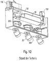
- the spotlight has a luminaire housing, which in the open state in Fig. 12 outlined is shown.
- the luminaire housing is intended to be mechanically and electrically connected to a busbar system (not shown) via adapters 150, 150 '.
- the luminaire housing comprises a profile-shaped bottom part 380 to which a luminaire head sleeve 200 for a lighting head or luminaire head 20 is attached, which can be set in different positions with respect to the luminaire housing.
- An L-shaped holding element made of sheet metal, which is riveted to the base part 380, is used to fasten the sleeve 200 to the base part 380.
- LED light-emitting diode
- An LED light source (LED: light-emitting diode) is arranged in the lamp head 20, for the operation of which the lamp also has an operating device 60; this is also arranged in the lamp housing, specifically in an upper receiving space 50.
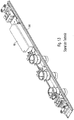
- Fig. 13 shows a corresponding base part of a further, similar lamp.
- the operating device 60 is also held on the base part 380.
- the holding elements are designed as bent sheet metal parts and are fixed to the base part 380 with grub screws.
- the attachment of the holding element or the holding elements to the base part 380 of the lamp housing requires a cost and installation effort that is not to be neglected in the manufacture of the lamp.
- a lighting system which has a rail-like profile element on which holding elements for operating devices can be clipped.
- a lamp with a profile-shaped lamp housing and an equipment carrier is known.
- the equipment rack is held on the luminaire housing by means of a latching connection.
- a ballast and means for fastening the wiring are arranged on the upper side of the equipment rack.
- the invention is based on the object of specifying an improved lamp.
- the luminaire should enable easier assembly and be able to be designed inexpensively.
- a lamp which has a lamp housing with a profile element, as well as a holding element arranged on the profile element for holding a further lamp component.
- the luminaire is designed in such a way that the holding element is arranged on the profile element in such a way that it is held only via a latching connection.
- This configuration allows the holding element to be connected to the profile element in a particularly simple manner.
- no separate fastening element is required for fastening the retaining element to the profile element. This means that the luminaire can be assembled in a particularly simple and time-saving manner.
- the holding element viewed in the longitudinal direction of the profile element, can in principle be attached at any point or position.
- the further luminaire component is an operating device of the luminaire.
- the latching connection preferably has at least one latching element formed on the holding element. This makes it easier for the holding element to be simply attached to the profile element for mounting the holding element. In addition, a corresponding separate component can hereby be avoided or saved.
- a particularly simple production of the holding element and assembly of the holding element on the profile element can be achieved if the holding element is made of plastic.
- the latching connection is preferably designed in such a way that it can be produced without tools and preferably also reversibly released again. This further simplifies the assembly of the lamp.
- a particularly simple assembly is also made possible if the latching connection - as provided according to the invention - is designed in such a way that it can be produced by a rotary movement of the holding element relative to the profile element.
- the lamp is further designed in such a way that the rotary movement takes place around an axis of rotation which runs parallel to a longitudinal axis of the profile element.
- the holding element preferably has an attachment element for an operating device of the lamp. This makes it easier to attach the operating device.
- the holding element has a strain relief element for strain relief of an electrical cable, which is provided for a power connection to the operating device. This saves a separate part for strain relief.
- the holding element preferably has a cable guide. This saves a separate part for guiding a cable for operating the lamp.
- the profile element is preferably a cover element of the lamp housing.
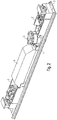
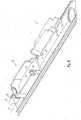
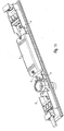
- Fig. 1 a sketch of a lamp according to the invention is shown.
- a profile element 2 which forms part of a lamp housing (otherwise not shown in the figure).
- the profile element 2 can be a cover element of the lamp housing, preferably - as is the case in the example shown - a base part of the lamp housing.
- Fig. 1 accordingly shows a view obliquely from above.
- the luminaire housing is designed in such a way that, when the luminaire is assembled, the in Fig. 1 sketched, encloses further parts. In this respect, the execution corresponds to that in Fig. 10 shown known lamp.
- the profile element 2 can, for example, alternatively be designed for a lateral covering of the lamp housing.
- the invention is suitable for any desired orientation of the profile element.
- the profile element 2 is a base part. If necessary, the directions etc. must be reinterpreted accordingly.
- a longitudinal axis L is defined by the shape of the profile element 2.
- the profile element 2 is sketched a little larger.
- the profile element 2 has two edge areas which extend parallel to the longitudinal axis L, a first upwardly directed leg 21 being formed on a first of the two edge areas and a second upwardly directed leg 22 on a second of the two edge areas
- Part of the profile element 2 is preferably designed at least substantially in the form of a plate, so that the profile element is, so to speak, slightly C-shaped in cross section.
- the two mentioned legs 21, 22 are directed above towards an interior of the lamp housing.
- the first upwardly directed limb 21 has a shoulder limb 211 which points in the direction of the second upwardly directed limb 22.
- a further shoulder leg 212 is preferably provided on the first upwardly directed leg 21, which is formed on the side opposite to the first-mentioned shoulder leg 211.
- the last-mentioned, further shoulder leg 212 is provided for fastening the profile element 2 to the lamp housing.
- the profile element 2 is preferably designed symmetrically with respect to a vertical plane of symmetry which is oriented parallel to the longitudinal axis L.
- the second upwardly directed leg 22 has corresponding shoulder legs 221, 222.
- the luminaire also has a holding element 3 which is designed to hold a further luminaire component, here in the form of an operating device 6 of the luminaire.
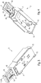
- the holding element 3 is sketched in a separated form obliquely from below, in Fig. 4 in a corresponding manner from diagonally above.
- the lamp is designed in such a way that the holding element 3 on the profile element 2 only - as in FIG Fig. 1 indicated - is arranged supported by a locking connection R.
- the holding element 3 can be fastened or mounted on the profile element 2 in a particularly simple manner.
- the holding element 3 preferably has at least one - for example in FIG Fig. 3 shown - locking element 7 on.
- the latching element 7 is designed to interact for the latching connection R with the shoulder leg 211 of the first upwardly directed leg 21 of the profile element 2.
- the holding element 3 also has a further latching element 71, which is designed to interact for the latching connection R with the shoulder leg 221 of the second upwardly directed leg 21 of the profile element 2, so that the two latching elements 7, 71 in opposite directions against the profile element Press 2 when the locking connection R is established as intended.
- the holding element 3 also has two further latching elements 72, 73, which are designed analogously to the two first-mentioned latching elements 7, 71, with reference to the longitudinal axis L at a different point .
- the holding element 3 is particularly suitably made of plastic, in particular it can be a molded plastic part. It is also preferably designed in one piece.
- the latching connection R can be made without tools. It can also be released again without tools; preferably the design is such that the holding element 3 with the Profile element 2 can be reversibly connected via the latching connection R and also detached again.
- Fig. 8 it is outlined how the holding element 3 can be mounted on the profile element 2.
- the latching connection R is designed in such a way that it can be produced by a rotary movement of the holding element 3 relative to the profile element 2.
- the holding element 3 can initially - in an inclined position - be attached to the second upwardly directed leg 22 of the profile element 2 with the two latching elements 71, 73 - as in FIG Fig. 8 indicated with a position I.
- the holding element 3 can be rotated about an axis of rotation D, which runs parallel to the longitudinal axis L, until the locking elements 7, 72 engage under the shoulder leg 211 to produce the locking connection R and thus finally a position II is reached, which is the one for one Operation of the lamp provided relative arrangement between the holding element 3 and the profile element 2 corresponds.
- the holding element 3 can, so to speak, be clipped onto the profile element 2.
- the holding element 3 can in principle be mounted at any point on the profile element 2 with respect to the longitudinal axis L.
- the holding element 3 preferably also has an attachment element 8 for connection to the operating device 6.
- the attachment element 8 is formed by two upwardly projecting shoulders 81, 82 which extend parallel to the longitudinal axis L.
- the operating device 6 can be connected relative to the holding element 8 with the latter in different longitudinal positions.
- the operating device 6 therefore does not have to be positioned with pinpoint accuracy for connection to the holding element 3 - with reference to the longitudinal axis L. In this way, the assembly of the operating device 6 is facilitated.
- the design is preferably such that the operating device 6 can be connected to the latter without tools for attachment to the holding element 3.
- the attachment element 8 is basically suitable for different operating devices.
- the holding element 3 further comprises a strain relief element 9.
- the strain relief element 9 is designed for strain relief of an electrical cable (not shown in the figures) which is provided for a power connection to the operating device 6.
- the strain relief element 9 is U-shaped, so that it has two U-legs 95, 96 and one connecting leg 99 connecting the two U-legs 95, 96; the two U-legs 95, 96 have - with reference to the U-shape - inwardly facing rows of teeth.
- the holding element 3 has two receiving areas 93, which are designed to receive the two U-legs 95, 96 in a latching manner and accordingly each have an outward-pointing edge which enables interaction with the corresponding row of teeth of the U-leg 95 or 96 is formed.
- the two receiving areas 93 are formed by vertically running, upwardly open openings, so that the strain relief element 9 with its two U-legs 95, 96 can be inserted into the receiving areas 93 from above.
- the receiving areas 93 can be formed, for example, by lateral recesses in the holding element 3.
- a first pressure surface 98 is formed between the two receiving areas 93 and a second pressure surface 97 is formed on the connecting leg 99, the two mentioned pressure surfaces 98, 97 being configured for pressing the electrical cable together.
- the design of the holding element 3 is preferably such that, in a first state of the holding element 3, the strain relief element 9 is connected to the rest of the holding element 3 only via at least one predetermined breaking point, here via two predetermined breaking points 91, 92. For assembly, this connection can then simply be released - for example by kinking - and then the strain relief element 9 with its two U-legs 95, 96 from above into the two Introduce receiving areas 93, the cable being clamped between the two pressure surfaces 98, 97 for strain relief.
- Fig. 1 a state is sketched in which the strain relief element 9 is correspondingly connected to the rest of the holding element 3 (in the drawing without a cable).
- the holding element 3 preferably has at least one - for example in the Figures 3 and 4 sketched - further attachment element 11 for one - in Fig. 1 Outlined - Terminal 10 for the cable on.
- the further attachment element 11 is designed in the form of at least one recess or a hole into which the clamp 10 can be inserted with a correspondingly corresponding projection.
- the lamp also has a further holding element 4.
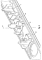
- the further holding element 4 is shown on a shorter section of the profile element 2 from a different viewing direction.
- the Figures 6 and 7 show the further holding element 4 in a separated form from two different directions of view obliquely from above.
- the further holding element 4 is designed to hold a lamp head sleeve 5.
- the lamp head sleeve 5 serves to receive a lamp head 50 which has a light source, for example an LED light source for emitting light from the lamp.
- the design is preferably such that the lamp head 50 is movably supported with respect to the lamp head sleeve 5, in particular in a vertical direction along a vertical axis A.
- a circular opening is formed in the profile element 2 through which the Lamp head 50 can be moved up and down along the axis A.
- the further holding element 4 has an upwardly directed extension 41.
- a clamp 52 is arranged around this extension 41 and the lamp head sleeve 5, so that the lamp head sleeve 5 is preferably mounted on the extension 41 so that it can rotate about the axis A.
- the further holding element 4 preferably has a concave bulge 47, the curvature of which is adapted to the shape of the lamp head sleeve 5. It is preferably designed in such a way that it forms a contact or sliding surface when the lamp head sleeve 5 rotates about the axis A.
- the extension 41 preferably has a nose 411 which serves as a rotary stop for a rotary movement of the lamp head sleeve 5 about the axis A.
- the further holding element 4 preferably has an attachment element 42 for the operating device 6, which is preferably designed analogously or structurally to the corresponding attachment element 8 of the first-mentioned holding element 3.
- the extension element 42 of the further holding element 3 is formed directly adjacent to the extension 41.
- the design is preferably such that the operating device 6 is held on the one hand on the holding element 3 and on the other hand on the further holding element 4.
- the further holding element 4 - like the first-mentioned holding element 3 - is arranged in a supported manner on the profile element 2 via a latching connection R '.
- the further holding element 4 has two latching elements 43, 44 which are designed to grip under the two facing shoulder legs 211, 221 of the two upwardly directed legs 21, 22 of the profile element 2.
- Fig. 9 it is outlined how the further holding element 4 can be mounted on the profile element 2.
- the latching connection R ' is designed such that it can be produced by a rotary movement or sliding rotary movement of the holding element 3 relative to the profile element 2, the rotary movement in this case running around a vertical axis of rotation D '.
- the further holding element 4 is first rotated by 90 ° with respect to its intended position - with the two latching elements 43, 44 between the two upwardly directed legs 21, 22 set. This is in Fig. 9 indicated with a position I.
- the further holding element 4 is then - as indicated by a position II - rotated about the axis of rotation D ' until the two latching elements 43, 44 finally engage under the shoulder legs 211, 221 in their intended positions, as indicated in a position III.
- This configuration also makes it possible to achieve that the holding element 3 can in principle be mounted at any point on the profile element 2 with respect to the longitudinal axis L.
- the further holding element 4 preferably has at least one cable guide 48, preferably two cable guides 48, which are designed to extend in particular parallel to the longitudinal axis L.
- the two cable guides 48 are preferably formed on two opposite sides of the attachment element 42, in particular at a level below the attachment element 42.
- a second holding element 3 ′ is also provided in addition to the first-mentioned holding element 3, which is constructed identically to the first-mentioned holding element 3.
- these holding elements 3, 3 ' are referred to as holding elements of a "first type".
- a second holding element 4 ' which is analogous or structurally identical to the latter, is also provided, as well as a corresponding third holding element 4 "- in the following these holding elements 4, 4', 4" are correspondingly used as holding elements of a "second Type ".
- two holding elements 3, 3 'of the first type and at least one holding element 4 of the second type are preferably provided.
- the two holding elements 3, 3 'of the first type are - with respect to the longitudinal axis L - preferably arranged at two opposite end regions of the profile element 2 and rotated by 180 ° to each other so that the two strain relief elements point outwards.
- These two holding elements 3, 3 'of the first type can serve as a clamp holder and strain relief for through-wiring the lamp.
- the holding element 4 or one of the holding elements 4 of the second type is preferably provided together with one of the two holding elements 3, 3 '- here with the holding element 3 - of the first type for holding the operating device 6.
- an adapter plate 11 can be provided which is designed so that it can be plugged onto the two corresponding attachment elements 8, 42 of the two holding elements 3, 4, as indicated by two arrows in FIG Fig. 10 indicated. On the adapter plate 11 can then - as in Fig. 11 shown - the operating device 6 can be attached in a further step.
- a first holding element 4 of the second type for holding a first lamp head sleeve 5 can be used.
- the two further holding elements 4, 4 'of the second type each serve to hold a further lamp head sleeve 5', 5 ".
- the holding elements 4, 4 ', 4" of the second type are - with reference to the longitudinal axis L - between the two holding elements 3, 3 'of the first type.
- the invention makes it possible to achieve that the luminaire can be manufactured in a significantly reduced assembly time and with a reduced number of components.
Landscapes
- Engineering & Computer Science (AREA)
- General Engineering & Computer Science (AREA)
- Power Engineering (AREA)
- Fastening Of Light Sources Or Lamp Holders (AREA)
- Non-Portable Lighting Devices Or Systems Thereof (AREA)
- Arrangement Of Elements, Cooling, Sealing, Or The Like Of Lighting Devices (AREA)
Description
- Die Erfindung betrifft eine Leuchte, die ein Leuchtengehäuse mit einem Profilelement aufweist.
- Eine solche Leuchte in Form eines Strahlers ist aus der
EP 2 138 763 A2 bekannt. Der Strahler weist ein Leuchtengehäuse auf, das in geöffnetem Zustand inFig. 12 skizziert gezeigt ist. Das Leuchtengehäuse ist dafür vorgesehen, über Adapter 150, 150' mit einem (nicht gezeigten) Stromschienensystem mechanisch und elektrisch verbunden zu werden. Das Leuchtengehäuse umfasst ein profilförmig gestaltetes Bodenteil 380, an dem eine Leuchtenkopfhülse 200 für einen Beleuchtungskopf bzw. Leuchtenkopf 20 befestigt ist, der gegenüber dem Leuchtengehäuse in unterschiedliche Positionen eingestellt werden kann. Zu der Befestigung der Hülse 200 an dem Bodenteil 380 dient ein L-förmiges Halteelement aus Blech, das mit dem Bodenteil 380 vernietet ist. - In dem Leuchtenkopf 20 ist eine LED-Lichtquelle (LED: Licht emittierende Diode) angeordnet, zu deren Betrieb die Leuchte weiterhin ein Betriebsgerät 60 aufweist; dieses ist ebenfalls in dem Leuchtengehäuse, und zwar in einem oberen Aufnahmeraum 50 angeordnet.
-
Fig. 13 zeigt ein entsprechendes Bodenteil einer weiteren, ähnlichen Leuchte. Bei dieser Ausführung ist auch das Betriebsgerät 60 an dem Bodenteil 380 gehaltert. Die Halteelemente sind hierbei als abgekantete Blechteile gestaltet und an dem Bodenteil 380 mit Madenschrauben fixiert. - Die Befestigung des Halteelements bzw. der Halteelemente an dem Bodenteil 380 des Leuchtengehäuses erfordert einen nicht zu vernachlässigenden Kosten- und Montageaufwand bei der Herstellung der Leuchte.
- Aus der
WO 2010/134887 A2 ist ein Leuchtsystem bekannt, das ein schienenartiges Profilelement aufweist, an dem Halteelemente für Betriebsgeräte eingeklipst werden können. - Aus der
EP 1 293 724 A1 ist ein Lichtkanalsystem mit einem Tragprofil bekannt, in dem sich Leuchtmodule einrasten lassen. - Aus der
US 2005/0002182 A1 ist eine Leuchtanordnung mit einem Profilelement bekannt, in das eine Kassette mit Leuchtelementen eingerastet werden kann. - Aus der
DE 10 2008 051 481 A1 ist eine Leuchte mit einem profilförmigen Leuchtengehäuse und einem Geräteträger bekannt. Der Geräteträger ist über eine Rastverbindung an dem Leuchtengehäuse gehalten. An der Oberseite des Geräteträgers sind ein Vorschaltgerät und Mittel zur Befestigung der Verdrahtung angeordnet. - Der Erfindung liegt die Aufgabe zugrunde, eine verbesserte Leuchte anzugeben. Insbesondere soll die Leuchte eine erleichterte Montage ermöglichen und kostengünstig gestaltet werden können.
- Diese Aufgabe wird gemäß der Erfindung mit dem in dem unabhängigen Anspruch angegebenen Gegenstand gelöst. Besondere Ausführungsarten der Erfindung sind in den abhängigen Ansprüchen angegeben.
- Gemäß der Erfindung ist eine Leuchte vorgesehen, die ein Leuchtengehäuse mit einem Profilelement aufweist, sowie ein, an dem Profilelement angeordnetes Halteelement zur Halterung eines weiteren Leuchtenbauteils. Dabei ist die Leuchte derart gestaltet, dass das Halteelement an dem Profilelement lediglich über eine Rastverbindung gehaltert angeordnet ist.
- Durch diese Ausgestaltung lässt sich das Halteelement besonders einfach mit dem Profilelement verbinden. Zudem ist dabei kein gesondertes Befestigungselement zur Befestigung des Halteelements an dem Profilelement erforderlich. Somit lässt sich die Leuchte besonders einfach und zeitsparend zusammenbauen.
- Dadurch, dass die Rastverbindung an dem Profilelement angreift, lässt sich darüber hinaus erzielen, dass das Halteelement in Längsrichtung des Profilelements betrachtet grundsätzlich an einer beliebigen Stelle bzw. Position angebracht werden kann.
- Erfindungsgemäß handelt es sich bei dem weiteren Leuchtenbauteil um ein Betriebsgerät der Leuchte.
- Vorzugsweise weist die Rastverbindung wenigstens ein, an dem Halteelement ausgebildetes Rastelement auf. Hierdurch ist zur Montage des Halteelements ein einfaches Ansetzen des Halteelements an dem Profilelement erleichtert. Zudem lässt sich ein entsprechendes gesondertes Bauteil hierdurch vermeiden bzw. einsparen.
- Eine besonders einfache Herstellung des Halteelements und Montage des Halteelements an dem Profilelement lässt sich bewirken, wenn das Halteelement aus Kunststoff besteht.
- Vorzugsweise ist die Rastverbindung derart gestaltet, dass sie ohne Werkzeug hergestellt und vorzugsweise auch reversibel wieder gelöst werden kann. Hierdurch ist der Zusammenbau der Leuchte weiterhin erleichtert.
- Eine besonders einfache Montage ist weiterhin ermöglicht, wenn die Rastverbindung - wie erfindungsgemäß vorgesehen - derart gestaltet ist, dass sie durch eine Drehbewegung des Halteelements relativ zu dem Profilelement hergestellt werden kann. Erfindungsgemäß ist die Leuchte dabei weiterhin derart gestaltet, dass die Drehbewegung um eine Drehachse erfolgt, die parallel zu einer Längsachse des Profilelements verläuft.
- Vorzugsweise weist das Halteelement ein Ansatzelement für ein Betriebsgerät der Leuchte auf. Hierdurch ist ein Anbringen des Betriebsgeräts erleichtert.
- Erfindungsgemäß weist das Halteelement ein Zugentlastungselement für eine Zugentlastung eines elektrischen Kabels auf, das für eine Stromverbindung mit dem Betriebsgerät vorgesehen ist. Hierdurch lässt sich ein gesondertes Teil zur Zugentlastung einsparen.
- Vorzugsweise weist das Halteelement eine Kabelführung auf. Hierdurch lässt sich ein gesondertes Teil zur Führung eines Kabels zum Betrieb der Leuchte einsparen.
- Vorzugsweise ist das Profilelement ein Abdeckelement des Leuchtengehäuses.
- Die Erfindung wird im Folgenden anhand von Ausführungsbeispielen und mit Bezug auf die Zeichnungen näher erläutert. Es zeigen:
- Fig. 1
- eine perspektivische Skizze eines Profilelements und mehrerer Halteelemente sowie weiterer Leuchtenbauteile einer erfindungsgemäßen Leuchte von schräg oben,
- Fig. 2
- eine entsprechende Skizze zu einer Variante,
- Fig. 3
- eine perspektivische Skizze zu einem Halteelement von schräg unten,
- Fig. 4
- eine entsprechende Skizze von schräg oben,
- Fig. 5
- eine perspektivische Skizze zu einem weiteren Halteelement, montiert an einem Profilelement und mit Leuchtenkopfhülse,
- Fig. 6
- eine perspektivische Skizze des separierten weiteren Halteelements von schräg oben,
- Fig. 7
- eine entsprechende Skizze aus einem anderen Blickwinkel,
- Fig. 8
- eine Skizze zum Ablauf der Montage des zuerst genannten Halteelements am Profilelement,
- Fig. 9
- eine entsprechende Skizze zum Ablauf der Montage des weiteren Halteelements,
- Fig. 10
- eine Skizze zur Verwendung einer Adapterplatte als Geräteträger für ein Betriebsgerät der Leuchte,
- Fig. 11
- eine weitere Skizze hierzu, mit dem montierten Betriebsgerät,
- Fig. 12
- eine Skizze zu einer Leuchte gemäß dem Stand der Technik und
- Fig. 13
- eine Skizze zu einer weiteren Leuchte gemäß dem Stand der Technik.
- In
Fig. 1 ist eine Skizze zu einer erfindungsgemäßen Leuchte gezeigt. Man erkannt ein Profilelement 2, das Teil eines (ansonsten in der Figur nicht gezeigten) Leuchtengehäuses bildet. Insbesondere kann es sich bei dem Profilelement 2 um ein Abdeckelement des Leuchtengehäuses handeln, vorzugsweise - wie im gezeigten Beispiel der Fall - um ein Bodenteil des Leuchtengehäuses. - In der vorliegenden Beschreibung wird davon ausgegangen, dass das Profilelement 2 das restliche Leuchtengehäuse nach unten hin begrenzt bzw. von unten abdeckt.
Fig. 1 zeigt dementsprechend eine Ansicht von schräg oben. Das Leuchtengehäuse ist so gestaltet, dass es im zusammengebauten Zustand der Leuchte die inFig. 1 skizzierten, weitere Teilen umschließt. Insoweit entspricht die Ausführung der inFig. 10 gezeigten bekannten Leuchte. - Die genannte Ausgestaltung als Abdeckelement von unten ist jedoch nicht zwingend. Das Profilelement 2 kann beispielsweise alternativ für eine seitliche Abdeckung des Leuchtengehäuses ausgestaltet sein. Grundsätzlich eignet sich die Erfindung für eine insoweit beliebige Orientierung des Profilelements. Lediglich der einfacheren Beschreibung wird hier davon ausgegangen, dass es sich bei dem Profilelement 2 um ein Bodenteil handelt. Gegebenenfalls sind die Richtungsangaben etc. entsprechend umzudeuten.
- Durch die Form des Profilelements 2 ist eine Längsachse L festgelegt. In
Fig. 5 ist das Profilelement 2 etwas größer skizziert. Das Profilelement 2 weist zwei Randbereiche auf, die sich parallel zu der Längsachse L erstrecken, wobei an einem ersten der beiden Randbereiche ein erster nach oben gerichteter Schenkel 21 ausgebildet ist und an einem zweiten der beiden Randbereiche ein zweiter nach oben gerichteter Schenkel 22. Der restliche Teil des Profilelements 2 ist vorzugsweise zumindest im Wesentlichen plattenförmig ausgestaltet, so dass das Profilelement im Querschnitt sozusagen leicht C-förmig gestaltet ist. Allgemeiner formuliert sind also die beiden genannten Schenkel 21, 22 zu einem Innenraum des Leuchtengehäuses hin vorstehend gerichtet. - Der erste nach oben gerichtete Schenkel 21 weist einen Schulterschenkel 211 auf, der in Richtung auf den zweiten nach oben gerichteten Schenkel 22 weist. Außerdem ist an dem ersten nach oben gerichteten Schenkel 21 vorzugsweise noch ein weiterer Schulterschenkel 212 vorgesehen, der auf der, dem zuerst genannten Schulterschenkel 211 entgegengesetzten Seite ausgebildet ist. Der zuletzt genannte, weitere Schulterschenkel 212 ist zur Befestigung des Profilelements 2 an dem Leuchtengehäuse vorgesehen.
- Das Profilelement 2 ist vorzugsweise symmetrisch ausgebildet, und zwar mit Bezug auf eine vertikale Symmetrieebene, die parallel zu der Längsachse L orientiert ist.
- Dementsprechend weist der zweite nach oben gerichtete Schenkel 22 entsprechende, Schulterschenkel 221, 222 auf.
- Wieder mit Bezug auf
Fig. 1 weist die Leuchte weiterhin ein Halteelement 3 auf, das zur Halterung eines weiteren Leuchtenbauteils, hier in Form eines Betriebsgeräts 6 der Leuchte ausgestaltet ist. InFig. 3 ist das Halteelement 3 in separierter Form von schräg unten skizziert, inFig. 4 in entsprechender Weise von schräg oben. Die Leuchte ist derart gestaltet, dass das Halteelement 3 an dem Profilelement 2 lediglich - wie inFig. 1 angedeutet - über eine Rastverbindung R gehaltert angeordnet ist. Hierdurch lässt sich das Halteelement 3 besonders einfach an dem Profilelement 2 befestigen bzw. montieren. - Vorzugsweise weist das Halteelement 3 hierzu wenigstens ein - beispielhaft in
Fig. 3 gezeigtes - Rastelement 7 auf. Das Rastelement 7 ist im gezeigten Beispiel dazu ausgebildet, zur Rastverbindung R mit dem Schulterschenkel 211 des ersten nach oben gerichteten Schenkels 21 des Profilelements 2 zusammenzuwirken. Vorzugsweise weist das Halteelement 3 außerdem ein weiteres Rastelement 71 auf, das dazu ausgestaltet ist, zur Rastverbindung R mit dem Schulterschenkel 221 des zweiten nach oben gerichteten Schenkels 21 des Profilelements 2 zusammenzuwirken, so dass die beiden Rastelemente 7, 71 in entgegengesetzte Richtungen gegen das Profilelement 2 drücken, wenn die Rastverbindung R wie vorgesehen hergestellt ist. - Eine besonders gute Stabilität der Verbindung lässt sich erzielen, wenn das Halteelement 3 außerdem noch zwei weitere Rastelemente 72, 73 aufweist, die analog zu den beiden zuerst genannten Rastelementen 7, 71 ausgestaltet sind, und zwar mit Bezug auf die Längsachse L an einer anderen Stelle.
- Besonders geeignet besteht das Halteelement 3 aus Kunststoff, insbesondere kann es sich um ein Kunststoff-Formteil handeln. Weiterhin vorzugsweise ist es einstückig ausgebildet.
- Mit der hier gezeigten Ausführung lässt sich erzielen, dass die Rastverbindung R ohne Werkzeug hergestellt werden kann. Sie kann auch ohne Werkzeug wieder gelöst werden; vorzugsweise ist die Gestaltung so, dass das Halteelement 3 mit dem Profilelement 2 über die Rastverbindung R reversibel verbunden und auch wieder gelöst werden kann.
- In
Fig. 8 ist skizziert, wie das Halteelement 3 an dem Profilelement 2 montiert werden kann. Im gezeigten Beispiel ist die Rastverbindung R derart gestaltet, dass sie durch eine Drehbewegung des Halteelements 3 relativ zu dem Profilelement 2 hergestellt werden kann. Hierzu kann das Halteelement 3 zunächst - in einer schrägen Position - mit den beiden Rastelementen 71, 73 an dem zweiten nach oben gerichteten Schenkel 22 des Profilelements 2 angesetzt werden - so wie inFig. 8 mit einer Position I angedeutet. Anschließend lässt sich das Halteelement 3 um eine Drehachse D drehen, die parallel zu der Längsachse L verläuft, bis die Rastelemente 7, 72 zur Herstellung der Rastverbindung R einrastend unter den Schulterschenkel 211 greifen und somit schließlich eine Position II erreicht ist, die der für einen Betrieb der Leuchte vorgesehenen Relativanordnung zwischen dem Halteelement 3 und dem Profilelement 2 entspricht. Das Halteelement 3 kann sozusagen an dem Profilelement 2 eingeklipst werden. - Durch diese Ausgestaltung lässt sich insbesondere erzielen, dass das Halteelement 3 mit Bezug auf die Längsachse L grundsätzlich an einer beliebigen Stelle an dem Profilelement 2 montiert werden kann.
- Wie in
Fig. 4 beispielhaft gezeigt, weist das Halteelement 3 vorzugsweise außerdem ein Ansatzelement 8 für die Verbindung mit dem Betriebsgerät 6 auf. Im gezeigten Beispiel ist das Ansatzelement 8 durch zwei nach oben ragende Schultern 81, 82 gebildet, die sich parallel zu der Längsachse L erstrecken. Hierdurch lässt sich das Betriebsgerät 6 relativ zu dem Halteelement 8 mit Letzterem in unterschiedlichen Längspositionen verbinden. Das Betriebsgerät 6 muss also zur Verbindung mit dem Halteelement 3 - mit Bezug auf die Längsachse L - nicht punktgenau angesetzt werden. Auf diese Weise ist die Montage des Betriebsgeräts 6 erleichtert. - Vorzugsweise ist die Gestaltung derart, dass das Betriebsgerät 6 zur Befestigung an dem Halteelement 3 werkzeuglos mit Letzterem verbunden werden kann.
- Das Ansatzelement 8 eignet sich dabei grundsätzlich für unterschiedliche Betriebsgeräte.
- Weiterhin umfasst das Halteelement 3 beim hier gezeigten Beispiel ein Zugentlastungselement 9. Das Zugentlastungselement 9 ist für eine Zugentlastung eines (in den Figuren nicht gezeigten) elektrischen Kabels ausgestaltet, das für eine Stromverbindung mit dem Betriebsgerät 6 vorgesehen ist.
- In der hier gezeigten Ausführung ist das Zugentlastungselement 9 U-förmig gestaltet, so dass es zwei U-Schenkel 95, 96 und einen, die beiden U-Schenkel 95, 96 verbindenden Verbindungsschenkel 99 aufweist; die beiden U-Schenkel 95, 96 weisen dabei - mit Bezug auf die U-Form - nach innen weisende Zahnreihen auf. Weiterhin weist das Halteelement 3 zwei Aufnahmebereiche 93 auf, die zur rastenden Aufnahme der beiden U-Schenkel 95, 96 ausgestaltet sind und dementsprechend jeweils eine nach außen weisende Kante aufweisen, die für eine Wechselwirkung mit der entsprechenden Zahnreihe des betreffenden U-Schenkels 95 bzw. 96 ausgebildet ist.
- Im gezeigten Beispiel sind die beiden Aufnahmebereiche 93 durch vertikal verlaufende, nach oben offene Öffnungen gebildet, so dass das Zugentlastungselement 9 mit seinen beiden U-Schenkeln 95, 96 von oben in die Aufnahmebereiche 93 eingeführt werden kann. Alternativ können die Aufnahmebereiche 93 beispielsweise durch seitliche Ausnehmungen des Halteelements 3 gebildet sein.
- Zwischen den beiden Aufhahmebereichen 93 ist eine erste Andruckfläche 98 ausgebildet und an dem Verbindungsschenkel 99 eine zweite Andruckfläche 97, wobei die beiden genannten Andruckflächen 98, 97 für ein Zusammendrücken des elektrischen Kabels ausgestaltet sind.
- Vorzugsweise ist die Gestaltung des Halteelements 3 derart, dass in einem ersten Zustand des Halteelements 3 das Zugentlastungselement 9 mit dem restlichen Halteelement 3 lediglich über wenigstens eine Sollbruchstelle, hier über zwei Sollbruchstellen 91, 92 verbunden ist. Zur Montage lässt sich dann diese Verbindung einfach lösen - zum Beispiel durch ein Abknicken - und im Weiteren das Zugentlastungselement 9 mit seinen beiden U-Schenkeln 95, 96 von oben in die beiden Aufnahmebereiche 93 einführen, wobei zwischen den beiden Andruckflächen 98, 97 das Kabel zur Zugentlastung eingeklemmt wird. In
Fig. 1 ist ein Zustand skizziert, in dem das Zugentlastungselement 9 entsprechend mit dem restlichen Halteelement 3 verbunden ist (in der Zeichnung ohne Kabel). - Weiterhin vorzugsweise weist das Halteelement 3 wenigstens ein - beispielhaft in den
Figuren 3 und 4 skizziertes - weiteres Ansatzelement 11 für eine - inFig. 1 skizzierte - Klemme 10 für das Kabel auf. Im gezeigten Beispiel ist das weitere Ansatzelement 11 in Form wenigstens einer Ausnehmung bzw. eines Lochs gestaltet, in das die Klemme 10 mit einem entsprechend korrespondierenden Vorsprung eingreifend eingesetzt werden kann. - Wie in
Fig. 1 weiterhin beispielhaft skizziert, weist die Leuchte außerdem ein weiteres Halteelement 4 auf. InFig. 5 ist das weitere Halteelement 4 an einem kürzeren Abschnitt des Profilelements 2 aus einer anderen Blickrichtung gezeigt. DieFiguren 6 und 7 zeigen das weitere Halteelement 4 in separierter Form aus zwei unterschiedlichen Blickrichtungen von schräg oben. - Das weitere Halteelement 4 ist zur Halterung einer Leuchtenkopfhülse 5 ausgestaltet. Die Leuchtenkopfhülse 5 dient zur Aufnahme eines Leuchtenkopfes 50, der eine Lichtquelle, beispielsweise eine LED-Lichtquelle zur Lichtabgabe der Leuchte aufweist. Die Gestaltung ist vorzugsweise derart, dass der Leuchtenkopf 50 gegenüber der Leuchtenkopfhülse 5 bewegbar gelagert ist, insbesondere in einer vertikalen Richtung entlang einer vertikalen Achse A. In der unteren Verlängerung der Leuchtenkopfhülse 5 ist hierzu im Profilelement 2 eine kreisförmige Öffnung ausgebildet, durch die hindurch der Leuchtenkopf 50 längs der Achse A auf und ab bewegt werden kann.
- Zur Halterung der Leuchtenkopfhülse 5 weist das weitere Halteelement 4 einen nach oben gerichteten Fortsatz 41 auf. Im gezeigten Beispiel ist eine Klammer 52 um diesen Fortsatz 41 und die Leuchtenkopfhülse 5 angeordnet, so dass vorzugsweise die Leuchtenkopfhülse 5 um die Achse A drehbar an dem Fortsatz 41 gelagert ist.
- An seinem unteren Endbereich weist das weitere Halteelement 4 vorzugsweise eine konkave Ausbuchtung 47 auf, die in ihrer Krümmung an die Form der Leuchtenkopfhülse 5 angepasst ist. Sie ist vorzugsweise derart gestaltet, dass sie eine Anlage- bzw. Gleitfläche bei einer Drehbewegung der Leuchtenkopfhülse 5 um die Achse A bildet.
- Der Fortsatz 41 weist an seinem oberen Ende vorzugsweise eine Nase 411 auf, die als Drehanschlag für eine Drehbewegung der Leuchtenkopfhülse 5 um die Achse A dient.
- Weiterhin vorzugsweise weist das weitere Halteelement 4 ein Ansatzelement 42 für das Betriebsgerät 6 auf, das vorzugsweise analog bzw. baugleich zu dem entsprechenden Ansatzelement 8 des zuerst genannten Halteelements 3 ausgebildet ist. Vorzugsweise ist das Ansatzelement 42 des weiteren Halteelements 3 unmittelbar an den Fortsatz 41 angrenzend ausgebildet.
- Wie in
Fig. 1 angedeutet, ist die Gestaltung dabei vorzugsweise derart, dass das Betriebsgerät 6 einerseits an dem Halteelement 3 und andererseits an dem weiteren Halteelement 4 gehaltert ist. - Das weitere Halteelement 4 ist - ebenso wie das zuerst genannte Halteelement 3 - über eine Rastverbindung R' an dem Profilelement 2 gehaltert angeordnet. Hierzu weist das weitere Halteelement 4 zwei Rastelemente 43, 44 auf, die dazu ausgestaltet sind, unter die beiden zueinander weisenden Schulterschenkel 211, 221 der beiden nach oben gerichteten Schenkel 21, 22 des Profilelements 2 zu greifen.
- In
Fig. 9 ist skizziert, wie das weitere Halteelement 4 an dem Profilelement 2 montiert werden kann. Im gezeigten Beispiel ist die Rastverbindung R' derart gestaltet, dass sie durch eine Drehbewegung bzw. Gleit-Drehbewegung des Halteelements 3 relativ zu dem Profilelement 2 hergestellt werden kann, wobei die Drehbewegung in diesem Fall um eine vertikale Drehachse D' verläuft. - Zur Herstellung der Rastverbindung R' wird das weitere Halteelement 4 zunächst - gegenüber seiner vorgesehenen Position um 90° verdreht - mit den zwei Rastelementen 43, 44 zwischen die beiden nach oben gerichteten Schenkel 21, 22 gesetzt. Dies ist in
Fig. 9 mit einer Position I angedeutet. Anschließend wird das weitere Halteelement 4 - wie durch eine Position II angedeutet - um die Drehachse D' gedreht, bis die beiden Rastelemente 43, 44 schließlich in ihren vorgesehenen Positionen rastend die Schulterschenkel 211, 221 untergreifen, wie in einer Position III angedeutet. - Auch durch diese Ausgestaltung lässt sich erzielen, dass das Halteelement 3 mit Bezug auf die Längsachse L grundsätzlich an einer beliebigen Stelle an dem Profilelement 2 montiert werden kann.
- Die genannte Bewegung des weiteren Halteelements 4 zu Herstellung der Verbindung lässt sich erleichtern, wenn die beiden Rastelemente 43, 44 jeweils konvex geformte Anlaufbereiche 431, 441 aufweisen.
- Weiterhin vorzugsweise weist das weitere Halteelement 4 wenigstens eine Kabelführung 48, vorzugsweise zwei Kabelführungen 48 auf, die sich insbesondere parallel zu der Längsachse L erstreckend ausgebildet sind. Die zwei Kabelführungen 48 sind vorzugsweise an zwei gegenüberliegenden Seiten von dem Ansatzelement 42 ausgebildet, insbesondere auf einem Niveau unterhalb des Ansatzelements 42.
- Bei dem in
Fig. 1 skizzierten Beispiel ist neben dem zuerst genannten Halteelement 3 außerdem noch ein zweites Halteelement 3' vorgesehen, das baugleich zu dem zuerst genannten Halteelement 3 gestaltet ist. Im Folgenden werden diese Halteelemente 3, 3' als Halteelemente eines "ersten Typs" bezeichnet. - Analog ist neben dem weiteren Halteelement 4 außerdem noch ein zweites, zu Letzterem analog bzw. baugleich gestaltetes Halteelement 4' vorgesehen, sowie ein entsprechendes drittes Halteelement 4" - im Folgenden werden diese Halteelemente 4, 4', 4" entsprechend als Halteelemente eines "zweiten Typs" bezeichnet.
- Bei der in
Fig. 1 skizzierten Anordnung sind an dem Profilelement 2 zwei Halteelemente 3, 3' des ersten Typs vorgesehen und insgesamt drei Halteelemente 4, 4', 4" des zweiten Typs. Bei der inFig. 2 skizzierten Variante des Profilelements 2 sind zwei Halteelemente 3, 3' des ersten Typs vorgesehen und genau ein Halteelement 4 des zweiten Typs. Dementsprechend sind bei der inFig. 1 skizzierten Anordnung drei Leuchtenkopfhülsen 5, 5', 5" vorgesehen und bei der inFig. 2 skizzierten Anordnung ist lediglich eine Leuchtenkopfhülse 5 vorgesehen. - Allgemein formuliert sind vorzugsweise zwei Halteelemente 3, 3' des ersten Typs vorgesehen und wenigstens ein Halteelement 4 des zweiten Typs.
- Die zwei Halteelemente 3, 3' des ersten Typs sind - mit Bezug auf die Längsachse L - vorzugsweise an zwei gegenüberliegenden Endbereichen des Profilelements 2 angeordnet und zwar dabei gegenseitig um 180° zueinander gedreht, so dass die beiden Zugentlastungselemente nach außen weisen. Diese beiden Halteelemente 3, 3' des ersten Typs können als Klemmenhalter und Zugentlaster für eine Durchverdrahtung der Leuchte dienen.
- Wie in
Fig. 10 angedeutet, ist vorzugsweise das Halteelement 4 bzw. eines der Halteelemente 4 des zweiten Typs zusammen mit einem der beiden Halteelemente 3, 3' - hier mit dem Halteelement 3 - des ersten Typs zur Halterung des Betriebsgeräts 6 vorgesehen. Hierzu kann insbesondere eine Adapterplatte 11 vorgesehen sein, die so gestaltet ist, dass sie auf die beiden entsprechenden Ansatzelemente 8, 42 der beiden Halteelemente 3, 4 aufgesteckt werden kann, wie durch zwei Pfeile inFig. 10 angedeutet. Auf der Adapterplatte 11 kann dann - wie inFig. 11 gezeigt - in einem weiteren Schritt das Betriebsgerät 6 befestigt werden. - Wieder mit Bezug auf die beispielhaft in
Fig. 1 gezeigte Anordnung kann ein erstes Halteelement 4 des zweiten Typs zur Halterung einer ersten Leuchtenkopfhülse 5 dienen. Die beiden weiteren Halteelemente 4, 4' des zweiten Typs dienen jeweils zur Halterung einer weiteren Leuchtenkopfhülse 5', 5". Die Halteelemente 4, 4', 4" des zweiten Typs sind dabei - mit Bezug auf die Längsachse L - zwischen den beiden Halteelementen 3, 3' des ersten Typs angeordnet. - Durch die Erfindung lässt sich erzielen, dass die Leuchte in deutlich reduzierter Montagezeit und dabei mit einer reduzierten Anzahl an Bauteilen hergestellt werden kann.
Claims (7)
- Leuchte, aufweisend- ein Leuchtengehäuse mit einem Profilelement (2),- ein, an dem Profilelement (2) angeordnetes Halteelement (3) zur Halterungeines weiteren Leuchtenbauteils (5, 6),
wobei die Leuchte derart gestaltet ist, dass das Halteelement (3) an dem Profilelement (2) lediglich über eine Rastverbindung (R) gehaltert angeordnet
ist,
wobei es sich bei dem weiteren Leuchtenbauteil um ein Betriebsgerät (6) der Leuchte handelt,
wobei das Halteelement (3) ein Zugentlastungselement (9) für eine Zugentlastung eines elektrischen Kabels aufweist, das für eine Stromverbindung mit dem Betriebsgerät (6) vorgesehen ist,
dadurch gekennzeichnet,
dass die Rastverbindung (R) derart gestaltet ist, dass sie durch eine Drehbewegung des Halteelements (3) relativ zu dem Profilelement (2) um eine parallel zu einer Längsachse (L) des Profilelements (2) verlaufende Drehachse (D) hergestellt werden kann. - Leuchte nach Anspruch 1,
bei der die Rastverbindung (R) wenigstens ein, an dem Halteelement (3) ausgebildetes Rastelement (7) aufweist. - Leuchte nach einem der vorhergehenden Ansprüche,
bei der das Halteelement (3) aus Kunststoff besteht. - Leuchte nach einem der vorhergehenden Ansprüche,
bei der die Rastverbindung (R) derart gestaltet ist, dass sie ohne Werkzeug hergestellt und vorzugsweise auch reversibel wieder gelöst werden kann. - Leuchte nach einem der vorhergehenden Ansprüche,
bei der das Halteelement (3) ein Ansatzelement (8) für das Betriebsgerät (6) der Leuchte aufweist. - Leuchte nach einem der vorhergehenden Ansprüche,
bei der ein weiteres Halteelement (4) eine Kabelführung (48) aufweist. - Leuchte nach einem der vorhergehenden Ansprüche,
bei der das Profilelement (2) ein Abdeckelement des Leuchtengehäuses ist.
Applications Claiming Priority (2)
| Application Number | Priority Date | Filing Date | Title |
|---|---|---|---|
| DE102012221454.2A DE102012221454B4 (de) | 2012-11-23 | 2012-11-23 | Leuchte mit einem Leuchtengehäuse, das ein Profilelement umfasst |
| PCT/EP2013/074378 WO2014079924A1 (de) | 2012-11-23 | 2013-11-21 | Leuchte mit einem leuchtengehäuse, das ein profilelement umfasst |
Publications (2)
| Publication Number | Publication Date |
|---|---|
| EP2923147A1 EP2923147A1 (de) | 2015-09-30 |
| EP2923147B1 true EP2923147B1 (de) | 2021-04-21 |
Family
ID=49674278
Family Applications (1)
| Application Number | Title | Priority Date | Filing Date |
|---|---|---|---|
| EP13796032.4A Active EP2923147B1 (de) | 2012-11-23 | 2013-11-21 | Leuchte mit einem leuchtengehäuse, das ein profilelement umfasst |
Country Status (5)
| Country | Link |
|---|---|
| US (1) | US10215382B2 (de) |
| EP (1) | EP2923147B1 (de) |
| CN (1) | CN104797883B (de) |
| DE (1) | DE102012221454B4 (de) |
| WO (1) | WO2014079924A1 (de) |
Families Citing this family (3)
| Publication number | Priority date | Publication date | Assignee | Title |
|---|---|---|---|---|
| US20140313747A1 (en) * | 2013-04-18 | 2014-10-23 | Robert Behnejad | Light emitting diode light bulb troffer |
| US20170198871A1 (en) * | 2016-01-11 | 2017-07-13 | John Keenan | Reconfigurable Lighting System |
| DE202019100149U1 (de) * | 2019-01-14 | 2020-04-15 | Zumtobel Lighting Gmbh | Leuchtmodul für ein Lichtbandsystem |
Citations (1)
| Publication number | Priority date | Publication date | Assignee | Title |
|---|---|---|---|---|
| DE102008051481A1 (de) * | 2007-11-06 | 2009-05-14 | Zumtobel Lighting Gmbh | Leuchte mit reflektierendem Geräteträger |
Family Cites Families (22)
| Publication number | Priority date | Publication date | Assignee | Title |
|---|---|---|---|---|
| CH669832A5 (en) | 1986-06-04 | 1989-04-14 | Ulmann Holding Ag | Supporting structure for light fittings - uses hollow rails with clips and supports inserted into longitudinal grooves for wall and ceiling mounting |
| EP0265892B1 (de) * | 1986-10-30 | 1991-06-05 | Pin Point Fibre Optics Limited | Montagen und Vorrichtungen zur Beleuchtung insbesondere Punktbeleuchtung |
| DE3825275A1 (de) | 1988-07-26 | 1990-02-01 | Edwin Deser | Lichtleiste |
| US5707136A (en) * | 1996-02-26 | 1998-01-13 | Byers; Thomas L. | Multiple light systems |
| US5848838A (en) * | 1997-05-15 | 1998-12-15 | Presta; Mike | Glass mounted light holding strip |
| DE29817256U1 (de) | 1998-09-25 | 1998-12-17 | Thorn Licht GmbH, 59755 Arnsberg | Tragschienenleuchte |
| US6217192B1 (en) * | 1999-06-01 | 2001-04-17 | Linard S. Stratton | Decorative light string support |
| DE10145499A1 (de) | 2001-09-14 | 2003-04-03 | Zumtobel Staff Gmbh & Co Kg | Lichtkanalsystem |
| US7025481B2 (en) * | 2003-03-18 | 2006-04-11 | Nexlite | Vehicular lighting system |
| US6896391B2 (en) * | 2003-07-01 | 2005-05-24 | Irwin Kotovsky | Method and apparatus for lighting with a cassette |
| DE10356064A1 (de) | 2003-12-01 | 2005-06-23 | Zumtobel Staff Gmbh | Profilrahmen-Leuchte |
| US8115411B2 (en) * | 2006-02-09 | 2012-02-14 | Led Smart, Inc. | LED lighting system |
| AT506521B1 (de) | 2008-02-22 | 2010-06-15 | Hierzer Andreas | Leuchtenprofil |
| US8042977B1 (en) * | 2008-05-05 | 2011-10-25 | Koninklijke Philips Electronics N.V. | Troffer luminaire |
| AT10865U1 (de) | 2008-06-27 | 2009-11-15 | Zumtobel Lighting Gmbh | Strahler und stromschienensystem mit einem solchen strahler |
| DE102008052869B4 (de) | 2008-09-15 | 2014-06-26 | Siteco Beleuchtungstechnik Gmbh | Leuchte mit LED-Tragschiene |
| KR101220657B1 (ko) * | 2008-11-28 | 2013-01-10 | 도시바 라이텍쿠 가부시키가이샤 | 조명기구 |
| SG176179A1 (en) * | 2009-05-19 | 2011-12-29 | Tian Tong Koh | Lighting system |
| JP2013521594A (ja) * | 2010-02-25 | 2013-06-10 | ビーイー・エアロスペース・インコーポレーテッド | Led照明素子 |
| US8888335B2 (en) * | 2010-06-24 | 2014-11-18 | GE Lighting Solutions, LLC | Lighting system |
| US8308323B2 (en) * | 2010-09-17 | 2012-11-13 | Darryl Holland | Magnetic light clip |
| US8490936B2 (en) * | 2011-05-04 | 2013-07-23 | Lance Rinck | Decorative light hanging system |
-
2012
- 2012-11-23 DE DE102012221454.2A patent/DE102012221454B4/de not_active Expired - Fee Related
-
2013
- 2013-11-21 EP EP13796032.4A patent/EP2923147B1/de active Active
- 2013-11-21 WO PCT/EP2013/074378 patent/WO2014079924A1/de not_active Ceased
- 2013-11-21 CN CN201380060251.2A patent/CN104797883B/zh not_active Expired - Fee Related
- 2013-11-21 US US14/646,679 patent/US10215382B2/en active Active
Patent Citations (1)
| Publication number | Priority date | Publication date | Assignee | Title |
|---|---|---|---|---|
| DE102008051481A1 (de) * | 2007-11-06 | 2009-05-14 | Zumtobel Lighting Gmbh | Leuchte mit reflektierendem Geräteträger |
Also Published As
| Publication number | Publication date |
|---|---|
| CN104797883A (zh) | 2015-07-22 |
| US10215382B2 (en) | 2019-02-26 |
| DE102012221454A1 (de) | 2014-05-28 |
| EP2923147A1 (de) | 2015-09-30 |
| CN104797883B (zh) | 2020-02-21 |
| WO2014079924A1 (de) | 2014-05-30 |
| US20150300611A1 (en) | 2015-10-22 |
| DE102012221454B4 (de) | 2022-06-23 |
Similar Documents
| Publication | Publication Date | Title |
|---|---|---|
| EP1848070B1 (de) | Elektrisches/elektronisches Installationsgerät | |
| AT12549U1 (de) | Vorrichtung zum befestigen und kontaktieren eines leuchtmittels und/oder eines leuchtmoduls, sowie leuchte | |
| EP2248503A1 (de) | Medizinische Versorgungseinheit mit verriegelbaren Adaptern | |
| AT14657U1 (de) | Leuchte mit auswechselbaren Leuchtmodulen | |
| DE102012016155B4 (de) | Türspiegel | |
| EP2081263B1 (de) | Steckdosenanordnung | |
| EP2827051B1 (de) | Leuchte | |
| DE102012221454B4 (de) | Leuchte mit einem Leuchtengehäuse, das ein Profilelement umfasst | |
| EP2365597B1 (de) | Drahthalter für eine Leuchte | |
| EP3165821B1 (de) | Längliches lichtbandelement | |
| EP4002615A1 (de) | Befestigung einer kupplung für ein lichtbandsystem | |
| DE10011613A1 (de) | Vorrichtung zur Montage und zum elektrischen Anschluß von Leuchten | |
| EP3007291B1 (de) | Drahthalter für eine leuchte | |
| EP2007251A1 (de) | Möbel | |
| EP2629004B1 (de) | Einbauleuchte für den Außenbereich, insbesondere zur Montage in einem Fensterrahmenprofil | |
| DE102018131996B4 (de) | Leuchte und zu deren Realisierung vorgesehenes System und Verfahren | |
| DE102024100353B4 (de) | Leuchte mit verriegelbarem Befestigungsabgriff und Verfahren zur Montage einer Leuchte | |
| DE102013011297B4 (de) | Vorrichtung zur elektrischen Kontaktierung eines oder mehrerer elektronischer Bauteile mit Versorgungsleitungen | |
| DE202009003604U1 (de) | Lampenfassung | |
| EP2469162B1 (de) | Haltevorrichtung für eine Leuchte | |
| EP1248037B1 (de) | Montagevorrichtung | |
| EP4646553A1 (de) | Lichtband mit indirektkomponente | |
| EP1037324A1 (de) | Verbinder für ein Koaxialkabel | |
| EP2018691A1 (de) | Anordnung für eine elektrische leitungsführung für led-leuchten | |
| DE102013104957B4 (de) | Steckverbindungsvorrichtung, Steckverbindung und konfektioniertes Kabel |
Legal Events
| Date | Code | Title | Description |
|---|---|---|---|
| PUAI | Public reference made under article 153(3) epc to a published international application that has entered the european phase |
Free format text: ORIGINAL CODE: 0009012 |
|
| 17P | Request for examination filed |
Effective date: 20150520 |
|
| AK | Designated contracting states |
Kind code of ref document: A1 Designated state(s): AL AT BE BG CH CY CZ DE DK EE ES FI FR GB GR HR HU IE IS IT LI LT LU LV MC MK MT NL NO PL PT RO RS SE SI SK SM TR |
|
| AX | Request for extension of the european patent |
Extension state: BA ME |
|
| RIN1 | Information on inventor provided before grant (corrected) |
Inventor name: HILDEBRANDT, EUGEN Inventor name: HESSE, PETER |
|
| DAX | Request for extension of the european patent (deleted) | ||
| STAA | Information on the status of an ep patent application or granted ep patent |
Free format text: STATUS: EXAMINATION IS IN PROGRESS |
|
| 17Q | First examination report despatched |
Effective date: 20180612 |
|
| RIC1 | Information provided on ipc code assigned before grant |
Ipc: F21Y 115/10 20160101ALN20201211BHEP Ipc: F21V 17/16 20060101ALI20201211BHEP Ipc: F21V 23/02 20060101ALI20201211BHEP Ipc: F21V 15/01 20060101ALI20201211BHEP Ipc: F21S 4/28 20160101AFI20201211BHEP |
|
| REG | Reference to a national code |
Ref country code: DE Ref legal event code: R079 Ref document number: 502013015668 Country of ref document: DE Free format text: PREVIOUS MAIN CLASS: F21V0017160000 Ipc: F21S0004280000 |
|
| GRAP | Despatch of communication of intention to grant a patent |
Free format text: ORIGINAL CODE: EPIDOSNIGR1 |
|
| STAA | Information on the status of an ep patent application or granted ep patent |
Free format text: STATUS: GRANT OF PATENT IS INTENDED |
|
| RIC1 | Information provided on ipc code assigned before grant |
Ipc: F21V 17/16 20060101ALI20210125BHEP Ipc: F21V 23/02 20060101ALI20210125BHEP Ipc: F21Y 115/10 20160101ALN20210125BHEP Ipc: F21V 15/01 20060101ALI20210125BHEP Ipc: F21S 4/28 20160101AFI20210125BHEP |
|
| GRAS | Grant fee paid |
Free format text: ORIGINAL CODE: EPIDOSNIGR3 |
|
| INTG | Intention to grant announced |
Effective date: 20210216 |
|
| GRAA | (expected) grant |
Free format text: ORIGINAL CODE: 0009210 |
|
| STAA | Information on the status of an ep patent application or granted ep patent |
Free format text: STATUS: THE PATENT HAS BEEN GRANTED |
|
| AK | Designated contracting states |
Kind code of ref document: B1 Designated state(s): AL AT BE BG CH CY CZ DE DK EE ES FI FR GB GR HR HU IE IS IT LI LT LU LV MC MK MT NL NO PL PT RO RS SE SI SK SM TR |
|
| REG | Reference to a national code |
Ref country code: GB Ref legal event code: FG4D Free format text: NOT ENGLISH |
|
| REG | Reference to a national code |
Ref country code: CH Ref legal event code: EP |
|
| REG | Reference to a national code |
Ref country code: DE Ref legal event code: R096 Ref document number: 502013015668 Country of ref document: DE |
|
| REG | Reference to a national code |
Ref country code: IE Ref legal event code: FG4D Free format text: LANGUAGE OF EP DOCUMENT: GERMAN |
|
| REG | Reference to a national code |
Ref country code: AT Ref legal event code: REF Ref document number: 1384999 Country of ref document: AT Kind code of ref document: T Effective date: 20210515 |
|
| REG | Reference to a national code |
Ref country code: LT Ref legal event code: MG9D |
|
| REG | Reference to a national code |
Ref country code: NL Ref legal event code: MP Effective date: 20210421 |
|
| PG25 | Lapsed in a contracting state [announced via postgrant information from national office to epo] |
Ref country code: HR Free format text: LAPSE BECAUSE OF FAILURE TO SUBMIT A TRANSLATION OF THE DESCRIPTION OR TO PAY THE FEE WITHIN THE PRESCRIBED TIME-LIMIT Effective date: 20210421 Ref country code: NL Free format text: LAPSE BECAUSE OF FAILURE TO SUBMIT A TRANSLATION OF THE DESCRIPTION OR TO PAY THE FEE WITHIN THE PRESCRIBED TIME-LIMIT Effective date: 20210421 Ref country code: LT Free format text: LAPSE BECAUSE OF FAILURE TO SUBMIT A TRANSLATION OF THE DESCRIPTION OR TO PAY THE FEE WITHIN THE PRESCRIBED TIME-LIMIT Effective date: 20210421 Ref country code: FI Free format text: LAPSE BECAUSE OF FAILURE TO SUBMIT A TRANSLATION OF THE DESCRIPTION OR TO PAY THE FEE WITHIN THE PRESCRIBED TIME-LIMIT Effective date: 20210421 Ref country code: BG Free format text: LAPSE BECAUSE OF FAILURE TO SUBMIT A TRANSLATION OF THE DESCRIPTION OR TO PAY THE FEE WITHIN THE PRESCRIBED TIME-LIMIT Effective date: 20210721 |
|
| REG | Reference to a national code |
Ref country code: DE Ref legal event code: R084 Ref document number: 502013015668 Country of ref document: DE |
|
| PG25 | Lapsed in a contracting state [announced via postgrant information from national office to epo] |
Ref country code: PT Free format text: LAPSE BECAUSE OF FAILURE TO SUBMIT A TRANSLATION OF THE DESCRIPTION OR TO PAY THE FEE WITHIN THE PRESCRIBED TIME-LIMIT Effective date: 20210823 Ref country code: PL Free format text: LAPSE BECAUSE OF FAILURE TO SUBMIT A TRANSLATION OF THE DESCRIPTION OR TO PAY THE FEE WITHIN THE PRESCRIBED TIME-LIMIT Effective date: 20210421 Ref country code: NO Free format text: LAPSE BECAUSE OF FAILURE TO SUBMIT A TRANSLATION OF THE DESCRIPTION OR TO PAY THE FEE WITHIN THE PRESCRIBED TIME-LIMIT Effective date: 20210721 Ref country code: ES Free format text: LAPSE BECAUSE OF FAILURE TO SUBMIT A TRANSLATION OF THE DESCRIPTION OR TO PAY THE FEE WITHIN THE PRESCRIBED TIME-LIMIT Effective date: 20210421 Ref country code: RS Free format text: LAPSE BECAUSE OF FAILURE TO SUBMIT A TRANSLATION OF THE DESCRIPTION OR TO PAY THE FEE WITHIN THE PRESCRIBED TIME-LIMIT Effective date: 20210421 Ref country code: SE Free format text: LAPSE BECAUSE OF FAILURE TO SUBMIT A TRANSLATION OF THE DESCRIPTION OR TO PAY THE FEE WITHIN THE PRESCRIBED TIME-LIMIT Effective date: 20210421 Ref country code: GR Free format text: LAPSE BECAUSE OF FAILURE TO SUBMIT A TRANSLATION OF THE DESCRIPTION OR TO PAY THE FEE WITHIN THE PRESCRIBED TIME-LIMIT Effective date: 20210722 Ref country code: IS Free format text: LAPSE BECAUSE OF FAILURE TO SUBMIT A TRANSLATION OF THE DESCRIPTION OR TO PAY THE FEE WITHIN THE PRESCRIBED TIME-LIMIT Effective date: 20210821 Ref country code: LV Free format text: LAPSE BECAUSE OF FAILURE TO SUBMIT A TRANSLATION OF THE DESCRIPTION OR TO PAY THE FEE WITHIN THE PRESCRIBED TIME-LIMIT Effective date: 20210421 |
|
| REG | Reference to a national code |
Ref country code: DE Ref legal event code: R097 Ref document number: 502013015668 Country of ref document: DE |
|
| PG25 | Lapsed in a contracting state [announced via postgrant information from national office to epo] |
Ref country code: RO Free format text: LAPSE BECAUSE OF FAILURE TO SUBMIT A TRANSLATION OF THE DESCRIPTION OR TO PAY THE FEE WITHIN THE PRESCRIBED TIME-LIMIT Effective date: 20210421 Ref country code: EE Free format text: LAPSE BECAUSE OF FAILURE TO SUBMIT A TRANSLATION OF THE DESCRIPTION OR TO PAY THE FEE WITHIN THE PRESCRIBED TIME-LIMIT Effective date: 20210421 Ref country code: CZ Free format text: LAPSE BECAUSE OF FAILURE TO SUBMIT A TRANSLATION OF THE DESCRIPTION OR TO PAY THE FEE WITHIN THE PRESCRIBED TIME-LIMIT Effective date: 20210421 Ref country code: DK Free format text: LAPSE BECAUSE OF FAILURE TO SUBMIT A TRANSLATION OF THE DESCRIPTION OR TO PAY THE FEE WITHIN THE PRESCRIBED TIME-LIMIT Effective date: 20210421 Ref country code: SK Free format text: LAPSE BECAUSE OF FAILURE TO SUBMIT A TRANSLATION OF THE DESCRIPTION OR TO PAY THE FEE WITHIN THE PRESCRIBED TIME-LIMIT Effective date: 20210421 Ref country code: SM Free format text: LAPSE BECAUSE OF FAILURE TO SUBMIT A TRANSLATION OF THE DESCRIPTION OR TO PAY THE FEE WITHIN THE PRESCRIBED TIME-LIMIT Effective date: 20210421 |
|
| PLBE | No opposition filed within time limit |
Free format text: ORIGINAL CODE: 0009261 |
|
| STAA | Information on the status of an ep patent application or granted ep patent |
Free format text: STATUS: NO OPPOSITION FILED WITHIN TIME LIMIT |
|
| 26N | No opposition filed |
Effective date: 20220124 |
|
| PG25 | Lapsed in a contracting state [announced via postgrant information from national office to epo] |
Ref country code: IS Free format text: LAPSE BECAUSE OF FAILURE TO SUBMIT A TRANSLATION OF THE DESCRIPTION OR TO PAY THE FEE WITHIN THE PRESCRIBED TIME-LIMIT Effective date: 20210821 Ref country code: AL Free format text: LAPSE BECAUSE OF FAILURE TO SUBMIT A TRANSLATION OF THE DESCRIPTION OR TO PAY THE FEE WITHIN THE PRESCRIBED TIME-LIMIT Effective date: 20210421 |
|
| PG25 | Lapsed in a contracting state [announced via postgrant information from national office to epo] |
Ref country code: MC Free format text: LAPSE BECAUSE OF FAILURE TO SUBMIT A TRANSLATION OF THE DESCRIPTION OR TO PAY THE FEE WITHIN THE PRESCRIBED TIME-LIMIT Effective date: 20210421 |
|
| PG25 | Lapsed in a contracting state [announced via postgrant information from national office to epo] |
Ref country code: LU Free format text: LAPSE BECAUSE OF NON-PAYMENT OF DUE FEES Effective date: 20211121 Ref country code: IT Free format text: LAPSE BECAUSE OF FAILURE TO SUBMIT A TRANSLATION OF THE DESCRIPTION OR TO PAY THE FEE WITHIN THE PRESCRIBED TIME-LIMIT Effective date: 20210421 Ref country code: BE Free format text: LAPSE BECAUSE OF NON-PAYMENT OF DUE FEES Effective date: 20211130 |
|
| REG | Reference to a national code |
Ref country code: BE Ref legal event code: MM Effective date: 20211130 |
|
| PG25 | Lapsed in a contracting state [announced via postgrant information from national office to epo] |
Ref country code: IE Free format text: LAPSE BECAUSE OF NON-PAYMENT OF DUE FEES Effective date: 20211121 |
|
| REG | Reference to a national code |
Ref country code: AT Ref legal event code: MM01 Ref document number: 1384999 Country of ref document: AT Kind code of ref document: T Effective date: 20211121 |
|
| PG25 | Lapsed in a contracting state [announced via postgrant information from national office to epo] |
Ref country code: AT Free format text: LAPSE BECAUSE OF NON-PAYMENT OF DUE FEES Effective date: 20211121 |
|
| PGFP | Annual fee paid to national office [announced via postgrant information from national office to epo] |
Ref country code: GB Payment date: 20221122 Year of fee payment: 10 Ref country code: FR Payment date: 20221122 Year of fee payment: 10 |
|
| PGFP | Annual fee paid to national office [announced via postgrant information from national office to epo] |
Ref country code: CH Payment date: 20221123 Year of fee payment: 10 |
|
| PG25 | Lapsed in a contracting state [announced via postgrant information from national office to epo] |
Ref country code: HU Free format text: LAPSE BECAUSE OF FAILURE TO SUBMIT A TRANSLATION OF THE DESCRIPTION OR TO PAY THE FEE WITHIN THE PRESCRIBED TIME-LIMIT; INVALID AB INITIO Effective date: 20131121 |
|
| PG25 | Lapsed in a contracting state [announced via postgrant information from national office to epo] |
Ref country code: CY Free format text: LAPSE BECAUSE OF FAILURE TO SUBMIT A TRANSLATION OF THE DESCRIPTION OR TO PAY THE FEE WITHIN THE PRESCRIBED TIME-LIMIT Effective date: 20210421 |
|
| P01 | Opt-out of the competence of the unified patent court (upc) registered |
Effective date: 20230530 |
|
| PG25 | Lapsed in a contracting state [announced via postgrant information from national office to epo] |
Ref country code: MK Free format text: LAPSE BECAUSE OF FAILURE TO SUBMIT A TRANSLATION OF THE DESCRIPTION OR TO PAY THE FEE WITHIN THE PRESCRIBED TIME-LIMIT Effective date: 20210421 |
|
| PG25 | Lapsed in a contracting state [announced via postgrant information from national office to epo] |
Ref country code: TR Free format text: LAPSE BECAUSE OF FAILURE TO SUBMIT A TRANSLATION OF THE DESCRIPTION OR TO PAY THE FEE WITHIN THE PRESCRIBED TIME-LIMIT Effective date: 20210421 |
|
| REG | Reference to a national code |
Ref country code: CH Ref legal event code: PL |
|
| PG25 | Lapsed in a contracting state [announced via postgrant information from national office to epo] |
Ref country code: CH Free format text: LAPSE BECAUSE OF NON-PAYMENT OF DUE FEES Effective date: 20231130 |
|
| GBPC | Gb: european patent ceased through non-payment of renewal fee |
Effective date: 20231121 |
|
| PG25 | Lapsed in a contracting state [announced via postgrant information from national office to epo] |
Ref country code: CH Free format text: LAPSE BECAUSE OF NON-PAYMENT OF DUE FEES Effective date: 20231130 |
|
| PG25 | Lapsed in a contracting state [announced via postgrant information from national office to epo] |
Ref country code: MT Free format text: LAPSE BECAUSE OF FAILURE TO SUBMIT A TRANSLATION OF THE DESCRIPTION OR TO PAY THE FEE WITHIN THE PRESCRIBED TIME-LIMIT Effective date: 20210421 |
|
| PG25 | Lapsed in a contracting state [announced via postgrant information from national office to epo] |
Ref country code: GB Free format text: LAPSE BECAUSE OF NON-PAYMENT OF DUE FEES Effective date: 20231121 |
|
| PG25 | Lapsed in a contracting state [announced via postgrant information from national office to epo] |
Ref country code: FR Free format text: LAPSE BECAUSE OF NON-PAYMENT OF DUE FEES Effective date: 20231130 |
|
| PG25 | Lapsed in a contracting state [announced via postgrant information from national office to epo] |
Ref country code: GB Free format text: LAPSE BECAUSE OF NON-PAYMENT OF DUE FEES Effective date: 20231121 Ref country code: FR Free format text: LAPSE BECAUSE OF NON-PAYMENT OF DUE FEES Effective date: 20231130 |
|
| PGFP | Annual fee paid to national office [announced via postgrant information from national office to epo] |
Ref country code: DE Payment date: 20241128 Year of fee payment: 12 |