EP2922178A2 - Motor - Google Patents
Motor Download PDFInfo
- Publication number
- EP2922178A2 EP2922178A2 EP15151623.4A EP15151623A EP2922178A2 EP 2922178 A2 EP2922178 A2 EP 2922178A2 EP 15151623 A EP15151623 A EP 15151623A EP 2922178 A2 EP2922178 A2 EP 2922178A2
- Authority
- EP
- European Patent Office
- Prior art keywords
- magnet
- pair
- flux
- corner
- magnets
- Prior art date
- Legal status (The legal status is an assumption and is not a legal conclusion. Google has not performed a legal analysis and makes no representation as to the accuracy of the status listed.)
- Granted
Links
- 230000004907 flux Effects 0.000 claims abstract description 155
- 230000004888 barrier function Effects 0.000 claims abstract description 126
- 230000007246 mechanism Effects 0.000 claims description 6
- 238000010586 diagram Methods 0.000 description 14
- 230000009467 reduction Effects 0.000 description 11
- 230000004048 modification Effects 0.000 description 6
- 238000012986 modification Methods 0.000 description 6
- 229910000831 Steel Inorganic materials 0.000 description 3
- 230000006872 improvement Effects 0.000 description 3
- 239000012212 insulator Substances 0.000 description 3
- 239000010959 steel Substances 0.000 description 3
- 239000000853 adhesive Substances 0.000 description 1
- 230000001070 adhesive effect Effects 0.000 description 1
- 230000007423 decrease Effects 0.000 description 1
- 230000000694 effects Effects 0.000 description 1
- 238000000034 method Methods 0.000 description 1
- 230000035699 permeability Effects 0.000 description 1
- 239000000126 substance Substances 0.000 description 1
Images


Classifications
-
- H—ELECTRICITY
- H02—GENERATION; CONVERSION OR DISTRIBUTION OF ELECTRIC POWER
- H02K—DYNAMO-ELECTRIC MACHINES
- H02K1/00—Details of the magnetic circuit
- H02K1/06—Details of the magnetic circuit characterised by the shape, form or construction
- H02K1/22—Rotating parts of the magnetic circuit
- H02K1/27—Rotor cores with permanent magnets
- H02K1/2706—Inner rotors
- H02K1/272—Inner rotors the magnetisation axis of the magnets being perpendicular to the rotor axis
- H02K1/274—Inner rotors the magnetisation axis of the magnets being perpendicular to the rotor axis the rotor consisting of two or more circumferentially positioned magnets
- H02K1/2753—Inner rotors the magnetisation axis of the magnets being perpendicular to the rotor axis the rotor consisting of two or more circumferentially positioned magnets the rotor consisting of magnets or groups of magnets arranged with alternating polarity
- H02K1/276—Magnets embedded in the magnetic core, e.g. interior permanent magnets [IPM]
- H02K1/2766—Magnets embedded in the magnetic core, e.g. interior permanent magnets [IPM] having a flux concentration effect
- H02K1/2773—Magnets embedded in the magnetic core, e.g. interior permanent magnets [IPM] having a flux concentration effect consisting of tangentially magnetized radial magnets
-
- H—ELECTRICITY
- H02—GENERATION; CONVERSION OR DISTRIBUTION OF ELECTRIC POWER
- H02K—DYNAMO-ELECTRIC MACHINES
- H02K1/00—Details of the magnetic circuit
- H02K1/06—Details of the magnetic circuit characterised by the shape, form or construction
- H02K1/22—Rotating parts of the magnetic circuit
- H02K1/27—Rotor cores with permanent magnets
- H02K1/2706—Inner rotors
- H02K1/272—Inner rotors the magnetisation axis of the magnets being perpendicular to the rotor axis
- H02K1/274—Inner rotors the magnetisation axis of the magnets being perpendicular to the rotor axis the rotor consisting of two or more circumferentially positioned magnets
- H02K1/2753—Inner rotors the magnetisation axis of the magnets being perpendicular to the rotor axis the rotor consisting of two or more circumferentially positioned magnets the rotor consisting of magnets or groups of magnets arranged with alternating polarity
- H02K1/276—Magnets embedded in the magnetic core, e.g. interior permanent magnets [IPM]
- H02K1/2766—Magnets embedded in the magnetic core, e.g. interior permanent magnets [IPM] having a flux concentration effect
-
- H—ELECTRICITY
- H02—GENERATION; CONVERSION OR DISTRIBUTION OF ELECTRIC POWER
- H02K—DYNAMO-ELECTRIC MACHINES
- H02K2213/00—Specific aspects, not otherwise provided for and not covered by codes H02K2201/00 - H02K2211/00
- H02K2213/03—Machines characterised by numerical values, ranges, mathematical expressions or similar information
Definitions
- the present invention relates to an electric motor.
- a spoke-type interior permanent magnet (IPM) motor in which magnets each having a rectangular cross section perpendicular to a central axis of the motor are arranged in a radial manner in a rotor core, is known.
- each magnet is magnetized such that long-side surfaces of the magnet have magnetic poles, and magnetic poles of the same polarity are arranged opposite to each other between circumferentially adjacent ones of the magnets.
- flux barriers are provided to direct magnetic flux toward a stationary portion of the motor, so that operating efficiency is improved.
- flux barriers which are cut portions each of which has a circumferential extent are provided between an outer circumference of a rotor and a radially outer end portion of each of permanent magnets.
- flux barriers which are a pair of holes are provided at a radially inner end portion of each magnet.
- spaces are arranged radially inside each of permanent magnets arranged in a spoke-like configuration such that the spaces adjoin two radially inner corners of each magnet.
- a motor includes a rotating portion arranged to rotate about a central axis; a stationary portion arranged around the rotating portion; and a bearing mechanism arranged to rotatably support the rotating portion.
- the rotating portion includes a plurality of magnets arranged in a circumferential direction, and a rotor core arranged to hold the plurality of magnets.
- the rotor core includes flux barriers defined therein, the flux barriers including first flux barrier pairs each of which includes a pair of the flux barriers.
- the plurality of magnets include two or more magnet pairs. Each of the plurality of magnets includes a pair of long sides and a pair of short sides in a cross section perpendicular to the central axis.
- the pair of long sides are magnetized to have mutually different polarities.
- magnetic poles of a same polarity are arranged circumferentially opposite to each other, and a center line between the pair of long sides of one of the magnets and a center line between the pair of long sides of the other magnet intersect each other at the central axis or at a point between the central axis and the magnet pair in a cross section perpendicular to the central axis.
- a corner of each of the magnets of each magnet pair, the corner lying on a short-side side closer to the central axis and on a side closer to the other magnet of the magnet pair, is arranged in a separate one of the flux barriers defined in the rotor core.
- the rotor core further includes an outer core portion arranged radially outside of the first flux barrier pairs, each first flux barrier pair adjoining a separate one of the magnet pairs; an inner core portion arranged radially inside of the first flux barrier pairs; and a joining portion arranged to join the outer core portion and the inner core portion to each other between the pair of the flux barriers of each of the first flux barrier pairs.
- the joining portion is arranged to have a minimum circumferential width smaller than a length of each short side.
- a vertical direction is defined as a direction in which a central axis of a motor extends, and that an upper side and a lower side along the central axis in Fig. 1 are referred to simply as an upper side and a lower side, respectively. It should be noted, however, that the above definitions of the vertical direction and the upper and lower sides should not be construed to restrict relative positions or directions of different members or portions when the motor is actually installed in a device.
- axial direction a direction parallel to the central axis
- radial direction a direction parallel to the central axis
- radial direction a direction parallel to the central axis
- radial direction a direction parallel to the central axis
- radial direction a direction parallel to the central axis
- radial direction a direction parallel to the central axis
- radial direction a direction parallel to the central axis
- radial direction centered on the central axis
- circumferential direction a circumferential direction about the central axis
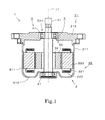
- FIG. 1 is a vertical cross-sectional view of a motor 1 according to a preferred embodiment of the present invention.
- the motor 1 is a rotary electrical machine.
- the motor 1 is of an inner-rotor type.
- the motor 1 includes a stationary portion 2, a rotating portion 3, and a bearing mechanism 4.
- the bearing mechanism 4 is arranged to support the rotating portion 3 such that the rotating portion 3 is rotatable about a central axis J1 of the motor 1 with respect to the stationary portion 2.
- the stationary portion 2 is arranged around the rotating portion 3.
- the stationary portion 2 includes a housing 21 and a stator 22.
- the housing 21 includes a housing member 211 and a cover member 212.
- the housing member 211 has a bottom and is substantially cylindrical.
- the housing member 211 includes a cylindrical portion 511 and a bottom portion 512.
- the cover member 212 is substantially rectangular, and is attached to a top portion of the cylindrical portion 511.
- the cover member 212 includes an opening 521 in a center thereof.
- the stator 22 includes a stator core 223, an insulator 221, and coils 222. Teeth of the stator core 223 are covered with the insulator 221.
- Each coil 222 is arranged on the insulator 221.
- the rotating portion 3 is caused to rotate about the central axis J1 through supply of power to the stationary portion 2.
- the bearing mechanism 4 includes two bearings 41.
- each bearing 41 is a ball bearing.
- the bearings 41 may alternatively have another structure.
- One of the bearings 41 is fixed to the cover member 212 in the opening 521.
- the other bearing 41 is fixed to the bottom portion 512.
- the rotating portion 3 includes a shaft 31, a rotor core 32, and a plurality of magnets 33.
- the shaft 31 is centered on the central axis J1.
- the shaft 31 is supported through the bearing mechanism 4 to be rotatable about the central axis J1.
- the rotor core 32 is substantially cylindrical, and is fixed to an outer circumference of the shaft 31.
- Each magnet 33 is a permanent magnet.
- the rotor core 32 is arranged radially inside of the stator 22. An outer circumferential surface of the rotor core 32 is arranged in proximity to an inner circumferential surface of the stator 22.
- FIG. 2 is a plan view illustrating the stator core 223, the rotor core 32, and the magnets 33.
- the stator core 223 includes a plurality of teeth 531 and a core back 532.
- the core back 532 is annular and is centered on the central axis J1.
- Each of the teeth 531 is arranged to extend radially inward from the core back 532 toward the rotor core 32.
- the stator core 223 is defined by laminated electromagnetic steel sheets.
- FIG. 3 is a perspective view illustrating the rotor core 32 and the magnets 33.
- the rotor core 32 is defined by laminated electromagnetic steel sheets.
- the rotor core 32 includes an outer core portion 321, an inner core portion 322, and a plurality of joining portions 323.
- the outer core portion 321 includes a plurality of outer core elements 541.
- the outer core elements 541 are arranged in a circumferential direction.
- the inner core portion 322 is arranged radially inside of the outer core portion 321.
- Each outer core element 541 is joined to the inner core portion 322 through one of the joining portions 323.
- Each joining portion 323 is arranged to extend in a radial direction.
- the outer core portion 321, the inner core portion 322, and the joining portions 323 are defined by a single continuous monolithic member.
- each outer core element 541 is convex, with a circumferential middle thereof being radially outward of both circumferential ends thereof.
- the outer circumferential surface of each outer core element 541 is arranged to have a radius of curvature smaller than a maximum radius of the outer core portion 321.
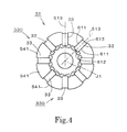
- FIG. 4 is a plan view of the rotor core 32 and the magnets 33.
- the magnets 33 are arranged between the outer core elements 541.
- the magnets 33 are arranged at regular intervals in the circumferential direction.
- the rotor core 32 is arranged to hold each magnet 33.
- Each magnet 33 includes a pair of long sides 611 and a pair of short sides 612 in a cross section perpendicular to the central axis J1.
- a center line 613 between the pair of long sides 611 of each magnet 33 passes through the central axis J1. That is, the center lines 613 of all the magnets 33 intersect one another at the central axis J1.
- the motor 1 is a spoke-type IPM motor.
- the pair of long sides 611 of each magnet 33 are magnetized to have mutually different polarities. Between adjacent ones of the magnets 33, magnetic poles of the same polarity are arranged circumferentially opposite to each other. This arrangement causes some magnetic lines of flux to be directed radially outwardly of the rotor core 32 from the long sides 611 opposed to each other through the outer circumferential surface of the outer core element 541 between the long sides 611, and then to enter back into the rotor core 32 through the outer circumferential surfaces of the adjacent outer core elements 541 on both sides to enter opposite magnetic poles. Of the plurality of magnets 33, pairs of two adjacent magnets 33, each pair having an identical structure, are repetitively arranged in the circumferential direction.
- each of such pairs of two adjacent magnets 33 will be hereinafter referred to as a "magnet pair" 330.
- a magnet pair 330
- four such magnet pairs 330 are arranged in the circumferential direction.
- Each outer core element 541 functions as a magnetic pole portion in relation to the stator 22.
- FIG. 5 is a diagram illustrating the rotor core 32 and the magnets 33 in an enlarged form.
- the outer core portion 321 and the inner core portion 322 are joined to each other through the plurality of joining portions 323.
- Flux barriers 62 are arranged on both circumferential sides of each joining portion 323 between the outer core element 541 and the inner core portion 322.
- Each flux barrier 62 is a space in which neither any portion of the rotor core 32 nor any portion of any magnet 33 exists.
- the outer core portion 321 is arranged radially outside of the flux barriers 62, while the inner core portion 322 is arranged radially inside of the flux barriers 62.
- each joining portion 323 is arranged between a pair of the flux barriers 62 between a separate pair of adjacent ones of the magnets 33.
- each flux barrier 62 is an air space. Because the air space has a magnetic permeability lower than that of the rotor core 32, each flux barrier 62 interferes with flow of magnetic flux.
- each flux barrier 62 may not necessarily be a space in which air exists, as long as the flux barrier 62 is a space that has a magnetic reluctance greater than that of any other portion of the rotor core 32.
- a substance other than air may exist in each flux barrier 62. The same is true of any other flux barrier described below.
- each magnet support portion 542 is arranged between two of the flux barriers 62 which adjoin each magnet 33.
- each magnet support portion 542 is assumed to be a portion of the inner core portion 322.
- the entire inner core portion 322 excluding the magnet support portions 542 will be hereinafter referred to as an "inner core cylindrical portion" 543.
- Each magnet support portion 542 is arranged to project radially outward from the inner core cylindrical portion 543, and a top of the magnet support portion 542 is arranged to be in contact with the short side 612 of a corresponding one of the magnets 33.
- the flux barriers 62 are spaces surrounded by the outer core elements 541, the joining portions 323, the inner core cylindrical portion 543, the magnets 33 and the magnet support portions 542.
- FIG. 6 is a diagram illustrating some of the flux barriers 62 and their vicinity. Since each corner 614 of each magnet 33 is arranged in one of the flux barriers 62, end points of a boundary between the flux barrier 62 and the magnet 33 lie on one of the long sides 611 which includes the corner 614 and one of the short sides 612 which includes the corner 614. Regarding each flux barrier 62, the length L1 of a portion of the long side 611 which lies in the flux barrier 62 is shorter than the length L2 of a portion of the short side 612 which lies in the flux barrier 62.
- a reduction in an extent to which the long side 611 is exposed in the flux barrier 62 makes it possible to efficiently direct magnetic flux from the magnet 33 into the outer core element 541 while reducing a leakage of magnetic flux into the flux barrier 62. Meanwhile, an increase in an extent to which the short side 612 is exposed in the flux barrier 62 contributes to reducing flow of magnetic flux toward the short side 612.
- the output in question here may be either a torque or the amount of energy per unit time.
- the flux barriers 62 can be easily provided when the corners 614 of the magnets 33 are arranged in the flux barriers 62.
- the length L1 of the portion of the long side 611 which lies in the flux barrier 62 were too short, a leakage of the magnetic flux into the flux barrier 62 would be significant. Therefore, the length L1 is preferably arranged to be in the range of 10% inclusive to 20% exclusive of the length of the long side 611.
- the length W1 (hereinafter referred to as the "contact length" W1 as appropriate) of an area over which the magnet support portion 542 and the short side 612 are in contact with each other decreases.
- the contact length W1 does not need to be extremely reduced, because performance of the motor 1 is not significantly affected by an increase in the contact length W1.
- the contact length W1 should have a reasonable magnitude so that the magnet 33 can be supported from radially inward.
- the contact length W1 refers to the length of the area over which the magnet support portion 542 and the short side 612 are actually in contact with each other, and does not refer to a maximum width of the magnet support portion 542.
- the contact length W1 is preferably arranged to be half or less than half the length of the short side 612.
- each joining portion 323 should have a small width in order to reduce flow of magnetic flux into the inner core portion 322.
- a small width of the joining portion 323 makes it easier for the joining portion 323 to reach magnetic saturation to block additional magnetic flux.
- the minimum width W2 of the joining portion 323 as measured in the circumferential direction that is, the minimum width of the joining portion 323 as measured in a direction perpendicular to a center line of the joining portion 323 extending in a radial direction, is preferably arranged to be equal to or smaller than the length of the short side 612.
- the minimum width W2 can be made significantly smaller than the length of the short side 612, and the minimum width W2 is more preferably arranged to be half or less than half the length of the short side 612. This arrangement makes it possible to achieve a reduction in the size of the motor 1 with a limited reduction in the output of the motor 1.
- Each joining portion 323 is preferably elongated, and is arranged to have a radial dimension greater than the circumferential width thereof.
- the radial dimension of the joining portion 323 corresponds to the radial width of the flux barrier 62, and that the circumferential width of the joining portion 323 is the minimum width W2.
- the minimum width W2 of the joining portion 323 is preferably smaller than the contact length W1, i.e., the length of the area over which the magnet support portion 542 and the short side 612 are in contact with each other, since the minimum width W2 of the joining portion 323 produces a greater effect on unwanted flow of magnetic flux than does the contact length W1.
- the joining portion 323 reaches magnetic saturation because of magnetic flux passing from the outer core portion 321 to the inner core portion 322 or magnetic flux passing from the inner core portion 322 to the outer core portion 321, and magnetic lines of flux are greatly directed radially outwardly of the outer core element 541 without permitting magnetic lines of flux to pass from the long side 611 of the magnet 33 to the inner core portion 322. This results in an improvement in the output of the motor 1.
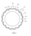
- FIG. 7 is a plan view illustrating a rotor core 32 and magnets 33 according to another preferred embodiment of the present invention.
- sixteen pairs of magnets 33 are provided, that is, the number of magnets 33 is thirty-two.
- a stator not shown includes a greater number of teeth than the number of teeth 531 in FIG. 2 .
- the rotor core 32 includes an inner core portion 322, an outer core portion 321, a plurality of first joining portions 324, and a plurality of second joining portions 325.
- the structure of a motor according to this preferred embodiment of the present invention is similar to the structure of the motor 1 illustrated in FIG. 1 except in that the shape of the rotor core 32 and arrangement of the magnets 33 are different.
- the outer core portion 321 is arranged radially outside of the inner core portion 322.
- the outer core portion 321 and the inner core portion 322 are joined to each other through the plurality of first joining portions 324 and the plurality of second joining portions 325.
- the outer core portion 321, the inner core portion 322, the first joining portions 324, and the second joining portions 325 are defined by a single continuous monolithic member.
- the magnets 33 are inserted in magnet holding holes 544 defined in the rotor core 32. Each magnet holding hole 544 extends in an axial direction.
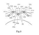
- FIG. 8 is a diagram illustrating a portion of the rotor core 32 and some of the magnets 33 in an enlarged form.
- each magnet 33 includes a pair of long sides 611 and a pair of short sides 612 in a cross section perpendicular to a central axis J1.
- the pair of long sides 611 of each magnet 33 are magnetized to have mutually different polarities.
- magnetic poles of the same polarity are arranged circumferentially opposite to each other.
- magnetic poles of opposite polarities are arranged circumferentially opposite to each other. Accordingly, when the rotor core 32 is viewed from radially outside, the polarity of magnetic poles facing radially outward and arranged in the circumferential direction is reversed every magnet pair 330.
- each magnet pair 330 a center line 613 between the pair of long sides 611 of one of the magnets 33 and a center line 613 between the pair of long sides 611 of the other magnet 33 intersect each other at a point between the central axis J1 and the magnet pair 330 in a cross section perpendicular to the central axis J1. That is, each magnet pair 330 is arranged in the shape of the letter "V", with two arms of the letter "V" being open more widely than they would be if they extended in radial directions centered on the central axis J1.
- Flux barriers 63a and 63b are arranged near both short sides 612 of each magnet 33.
- the flux barriers 63a arranged between the two magnets 33 which together define each magnet pair 330 will be hereinafter referred to as “first flux barriers” 63a, while the flux barriers 63b arranged circumferentially outside of each magnet pair 330 will be hereinafter referred to as “second flux barriers” 63b.
- Each of the first flux barriers 63a and the second flux barriers 63b is a portion of one of the magnet holding holes 544.
- Each of the first joining portions 324 is arranged between adjacent ones of the first flux barriers 63a.
- the adjacent ones of the first flux barriers 63a will be hereinafter referred to collectively as a "first flux barrier pair" 64a.
- Each second joining portion 325 is arranged between adjacent ones of the second flux barriers 63b between adjacent ones of the magnet pairs 330.
- the adjacent ones of the second flux barriers 63b will be hereinafter referred to collectively as a "second flux barrier pair" 64b.
- the outer core portion 321 is arranged radially outside of the first flux barrier pairs 64a, each of which adjoins a separate one of the magnet pairs 330, and radially outside of the second flux barrier pairs 64b.
- the inner core portion 322 is arranged radially inside of the first flux barrier pairs 64a and radially inside of the second flux barrier pairs 64b.
- Each first flux barrier pair 64a contributes to reducing flow of magnetic flux into the inner core portion 322, whereas each second flux barrier pair 64b contributes to preventing a short circuit of magnetic flux within the rotor core 32. Thus, a greater amount of magnetic flux is directed radially outwardly of the rotor core 32.
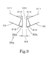
- FIG. 9 is a diagram illustrating one of the first flux barrier pairs 64a and its vicinity in an enlarged form.
- a corner 614 of each of the magnets 33 of each magnet pair 330 is arranged in a separate one of the first flux barriers 63a. End points of a boundary between each magnet 33 and a corresponding one of the first flux barriers 63a lie on one of the long sides 611 which includes the corner 614 and one of the short sides 612 which includes the corner 614 (in the case of FIG. 9 , on an end point of the short side 612).
- the above arrangement contributes to preventing magnetic flux from passing from the long side 611 facing an outer circumference of the rotor core 32 toward the inner core portion 322, making it possible to efficiently direct the magnetic flux radially outwardly of the outer core portion 321.
- the magnets 33 are arranged in the shape of the letter "V"
- a minimum width W2 of each first joining portion 324 is arranged to be smaller than the length of each short side 612. More preferably, the minimum width W2 of each first joining portion 324 is arranged to be half or less than half the length of each short side 612.
- Each first joining portion 324 is preferably arranged to have a small width, and the first joining portion 324 is arranged to have a radial dimension greater than the circumferential width thereof. These conditions also contribute to reducing flow of magnetic flux into the inner core portion 322, and achieving a reduction in the size of the motor 1. Definitions of the radial dimension and the circumferential width of the first joining portion 324 are similar to definitions of the radial dimension and the circumferential width, respectively, of the joining portion 323 illustrated in FIG. 6 .
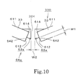
- FIG. 10 is a diagram illustrating a first flux barrier pair 64a according to another preferred embodiment of the present invention. Also in the preferred embodiment illustrated in FIG. 10 , end points of a boundary between a first flux barrier 63a and a magnet 33 lie on a long side 611 which includes a corner 614 and on a short side 612 which includes the corner 614. A portion of an inner core portion 322 which is in contact with the short side 612 functions as a magnet support portion 542. Thus, the magnet 33 is securely held.
- the length W1 (hereinafter referred to as the "contact length" W1 as appropriate) of an area over which the magnet support portion 542 and the short side 612 of the magnet 33 are in contact with each other may have a reasonable magnitude, and therefore, the minimum width W2 of a first joining portion 324 measured in the circumferential direction is preferably arranged to be smaller than the contact length W1, i.e., the length of the area over which the magnet support portion 542 and the short side 612 are in contact with each other.
- the length of a portion of the long side 611 which lies in the first flux barrier 63a is preferably arranged to be in the range of 10% inclusive to 20% exclusive of the length of the long side 611.
- FIG. 11 is a diagram illustrating a first flux barrier pair 64a according to yet another preferred embodiment of the present invention.
- end points of a boundary between a first flux barrier 63a and a corresponding magnet 33 lie on two long sides 611 of the magnet 33.
- a short side 612 of the magnet 33 lies in the first flux barrier 63a in its entirety.
- no magnet support portion 542 is provided, and therefore, the position of each magnet 33 in a corresponding magnet holding hole 544 is fixed by, for example, members attached to both axial ends of a rotor core 32.
- Absence of the magnet support portion 542 contributes to reducing the number of loops of magnetic lines of flux of a magnetic field of the magnet 33 itself which do not contribute to a torque and which enter the short side 612 of the magnet 33, and enables magnetic lines of flux to be greatly directed radially outwardly of an outer core element 541. As a result, an improvement in output of a motor 1 is achieved.
- FIG. 12 is a diagram illustrating a flux barrier 65 according to a modification of the above-described preferred embodiment illustrated in FIG. 6 .
- no magnet support portion 542 is provided in FIG. 12 .
- end points of a boundary between the flux barrier 65 and a corresponding magnet 33 lie on two long sides 611 of the magnet 33 as is similarly the case with the preferred embodiment illustrated in FIG. 11 .
- a short side 612 of the magnet 33 lies in the flux barrier 65 in its entirety.
- FIGS. 11 and 12 a structure illustrated in FIG. 12 corresponds to a modification of a structure illustrated in FIG. 11 in a special condition.
- a structure illustrated in FIG. 6 can be regarded as a modification of a basic structure illustrated in FIG. 10 .
- the first flux barrier pair 64a will be arranged between the two magnets 33 of each magnet pair 330. If the first flux barrier pair 64a is additionally arranged also between every adjacent ones of the magnet pairs 330, a structure equivalent to the structure illustrated in FIG. 6 results.
- FIGS. 6 and 10 suppose that the magnet 33 in the middle in FIG. 6 corresponds to the magnet 33 on the left-hand side in FIG. 10 .
- the magnet 33 in the middle and the magnet 33 on the right together define the magnet pair 330.
- the two flux barriers 62 between these magnets 33 of the magnet pair 330 correspond to the two first flux barriers 63a in FIG. 10 .
- each of the magnets 33 of the magnet pair 330 is arranged in a separate one of the flux barriers 62 between the two magnets 33 of the magnet pair 330. End points of a boundary between each magnet 33 and a corresponding one of the flux barriers 62 lie on the long side 611 including the corner 614 and on the short side 612 including the corner 614.
- another corner 614 of each of the magnets 33 of the magnet pair 330 is arranged in another one of the flux barriers 62.
- the other corner 614 on the left is arranged in another one of the flux barriers 62 than the flux barrier 62 in which the right corner 614 is arranged. End points of a boundary between this other one of the flux barriers 62 and the magnet 33 lie on the other one of the long sides 611 of the magnet 33, which includes the corner 614 on the left, and on the short side 612 which includes the corner 614 on the left.
- each including one magnet pair 330 and four flux barriers 62 are repetitively arranged in the circumferential direction. Therefore, another one of the joining portions 323 arranged to join the outer core portion 321 and the inner core portion 322 to each other is arranged between a pair of the flux barriers 62 which lie between every adjacent ones of the magnet pairs 330
- the outer core elements 541 lie between the two magnets 33 of each magnet pair 330 and between every adjacent ones of the magnet pairs 330.
- the structure illustrated in FIG. 6 corresponds to a modification of the structure illustrated in FIG. 10 as modified such that the magnets 33 are arranged in a radial manner and the flux barriers are arranged on both sides of each magnet 33.
- a structure in which the flux barriers 62 are provided for each of the pair of long sides 611 of each magnet 33 is suitable for the spoke-type IPM motor.
- motor 1 may be modified in a variety of manners.
- the number of poles of the rotating portion 3 and the number of poles of the stationary portion 2 may be modified in a variety of manners.
- a variety of methods may be adopted to fix each of the magnets 33 to the rotor core 32.
- each magnet 33 may be fixed to the rotor core 32 through an adhesive.
- a portion of the laminated electromagnetic steel sheets may be employed to fix the position of each magnet 33.
- the number of magnet pairs 330 may be any number greater than one.
- the housing 21 may be defined by three or more members combined together.
- Motors according to preferred embodiments of the present invention may be used as driving sources for a variety of applications.
Landscapes
- Engineering & Computer Science (AREA)
- Power Engineering (AREA)
- Permanent Field Magnets Of Synchronous Machinery (AREA)
- Permanent Magnet Type Synchronous Machine (AREA)
- Iron Core Of Rotating Electric Machines (AREA)
Abstract
Description
- The present invention relates to an electric motor.
- A spoke-type interior permanent magnet (IPM) motor, in which magnets each having a rectangular cross section perpendicular to a central axis of the motor are arranged in a radial manner in a rotor core, is known. In such a spoke-type motor, each magnet is magnetized such that long-side surfaces of the magnet have magnetic poles, and magnetic poles of the same polarity are arranged opposite to each other between circumferentially adjacent ones of the magnets. In the spoke-type IPM motor, flux barriers are provided to direct magnetic flux toward a stationary portion of the motor, so that operating efficiency is improved.
- For example, in a rotor illustrated in
FIG. 5 ofJP-A 2001-211582 FIG. 3 ofUS 2011/0290581 , spaces are arranged radially inside each of permanent magnets arranged in a spoke-like configuration such that the spaces adjoin two radially inner corners of each magnet. - Here, in order to miniaturize the spoke-type IPM motor, it is necessary to arrange the magnets radially inward. However, simply arranging the magnets radially inward would increase a leakage of magnetic flux into the flux barriers, and might permit magnetic flux to flow radially inward. This would cause a reduction in output of the motor even with use of the same magnets. This problem is also shared by IPM motors which are not of a spoke type.
- A motor according to a preferred embodiment of the present invention includes a rotating portion arranged to rotate about a central axis; a stationary portion arranged around the rotating portion; and a bearing mechanism arranged to rotatably support the rotating portion. The rotating portion includes a plurality of magnets arranged in a circumferential direction, and a rotor core arranged to hold the plurality of magnets. The rotor core includes flux barriers defined therein, the flux barriers including first flux barrier pairs each of which includes a pair of the flux barriers. The plurality of magnets include two or more magnet pairs. Each of the plurality of magnets includes a pair of long sides and a pair of short sides in a cross section perpendicular to the central axis. The pair of long sides are magnetized to have mutually different polarities. Within each of the two or more magnet pairs, magnetic poles of a same polarity are arranged circumferentially opposite to each other, and a center line between the pair of long sides of one of the magnets and a center line between the pair of long sides of the other magnet intersect each other at the central axis or at a point between the central axis and the magnet pair in a cross section perpendicular to the central axis. A corner of each of the magnets of each magnet pair, the corner lying on a short-side side closer to the central axis and on a side closer to the other magnet of the magnet pair, is arranged in a separate one of the flux barriers defined in the rotor core. End points of a boundary between each magnet and a corresponding one of the flux barriers lie on one of the pair of long sides which includes the corner and on one of the pair of short sides which includes the corner or another one of the pair of long sides. The rotor core further includes an outer core portion arranged radially outside of the first flux barrier pairs, each first flux barrier pair adjoining a separate one of the magnet pairs; an inner core portion arranged radially inside of the first flux barrier pairs; and a joining portion arranged to join the outer core portion and the inner core portion to each other between the pair of the flux barriers of each of the first flux barrier pairs. The joining portion is arranged to have a minimum circumferential width smaller than a length of each short side.
- According to the above preferred embodiment of the present invention, it is possible to achieve a reduction in the size of the motor with a limited reduction in output of the motor.
-
-
FIG. 1 is a vertical cross-sectional view of a motor according to a preferred embodiment of the present invention. -
FIG. 2 is a plan view illustrating a stator core, a rotor core, and magnets according to a preferred embodiment of the present invention. -
FIG. 3 is a perspective view illustrating the rotor core and the magnets. -
FIG. 4 is a plan view illustrating the rotor core and the magnets. -
FIG. 5 is a diagram illustrating the rotor core and the magnets in an enlarged form. -
FIG. 6 is a diagram illustrating flux barriers and their vicinity according to a preferred embodiment of the present invention. -
FIG. 7 is a plan view illustrating a rotor core and magnets according to another preferred embodiment of the present invention. -
FIG. 8 is a diagram illustrating a portion of the rotor core and some of the magnets in an enlarged form. -
FIG. 9 is a diagram illustrating a first flux barrier pair and its vicinity according to a preferred embodiment of the present invention in an enlarged form. -
FIG. 10 is a diagram illustrating a first flux barrier pair according to another preferred embodiment of the present invention. -
FIG. 11 is a diagram illustrating a first flux barrier pair according to yet another preferred embodiment of the present invention. -
FIG. 12 is a diagram illustrating a flux barrier according to a preferred embodiment of the present invention. - It is assumed herein that a vertical direction is defined as a direction in which a central axis of a motor extends, and that an upper side and a lower side along the central axis in
Fig. 1 are referred to simply as an upper side and a lower side, respectively. It should be noted, however, that the above definitions of the vertical direction and the upper and lower sides should not be construed to restrict relative positions or directions of different members or portions when the motor is actually installed in a device. Also note that a direction parallel to the central axis is referred to by the term "axial direction", "axial", or "axially", that radial directions centered on the central axis are simply referred to by the term "radial direction", "radial", or "radially", and that a circumferential direction about the central axis is simply referred to by the term "circumferential direction", "circumferential", or "circumferentially". -
FIG. 1 is a vertical cross-sectional view of amotor 1 according to a preferred embodiment of the present invention. InFIG. 1 , parallel oblique lines for details of a section of themotor 1 are omitted. Themotor 1 is a rotary electrical machine. Themotor 1 is of an inner-rotor type. Themotor 1 includes astationary portion 2, a rotatingportion 3, and abearing mechanism 4. Thebearing mechanism 4 is arranged to support the rotatingportion 3 such that the rotatingportion 3 is rotatable about a central axis J1 of themotor 1 with respect to thestationary portion 2. - The
stationary portion 2 is arranged around the rotatingportion 3. Thestationary portion 2 includes ahousing 21 and astator 22. Thehousing 21 includes ahousing member 211 and acover member 212. Thehousing member 211 has a bottom and is substantially cylindrical. Thehousing member 211 includes acylindrical portion 511 and abottom portion 512. Thecover member 212 is substantially rectangular, and is attached to a top portion of thecylindrical portion 511. Thecover member 212 includes an opening 521 in a center thereof. Thestator 22 includes astator core 223, aninsulator 221, andcoils 222. Teeth of thestator core 223 are covered with theinsulator 221. Eachcoil 222 is arranged on theinsulator 221. The rotatingportion 3 is caused to rotate about the central axis J1 through supply of power to thestationary portion 2. - The
bearing mechanism 4 includes twobearings 41. According to the present preferred embodiment, each bearing 41 is a ball bearing. Note that thebearings 41 may alternatively have another structure. One of thebearings 41 is fixed to thecover member 212 in theopening 521. Theother bearing 41 is fixed to thebottom portion 512. - The rotating
portion 3 includes ashaft 31, arotor core 32, and a plurality ofmagnets 33. Theshaft 31 is centered on the central axis J1. Theshaft 31 is supported through thebearing mechanism 4 to be rotatable about the central axis J1. Therotor core 32 is substantially cylindrical, and is fixed to an outer circumference of theshaft 31. Eachmagnet 33 is a permanent magnet. Therotor core 32 is arranged radially inside of thestator 22. An outer circumferential surface of therotor core 32 is arranged in proximity to an inner circumferential surface of thestator 22. -
FIG. 2 is a plan view illustrating thestator core 223, therotor core 32, and themagnets 33. Thestator core 223 includes a plurality ofteeth 531 and a core back 532. The core back 532 is annular and is centered on the central axis J1. Each of theteeth 531 is arranged to extend radially inward from the core back 532 toward therotor core 32. Thestator core 223 is defined by laminated electromagnetic steel sheets. -
FIG. 3 is a perspective view illustrating therotor core 32 and themagnets 33. Therotor core 32 is defined by laminated electromagnetic steel sheets. Referring toFIGS. 2 and3 , therotor core 32 includes anouter core portion 321, aninner core portion 322, and a plurality of joiningportions 323. Theouter core portion 321 includes a plurality of outercore elements 541. Theouter core elements 541 are arranged in a circumferential direction. Theinner core portion 322 is arranged radially inside of theouter core portion 321. Eachouter core element 541 is joined to theinner core portion 322 through one of the joiningportions 323. Each joiningportion 323 is arranged to extend in a radial direction. Theouter core portion 321, theinner core portion 322, and the joiningportions 323 are defined by a single continuous monolithic member. - An outer circumferential surface of each
outer core element 541 is convex, with a circumferential middle thereof being radially outward of both circumferential ends thereof. The outer circumferential surface of eachouter core element 541 is arranged to have a radius of curvature smaller than a maximum radius of theouter core portion 321. By arranging the outer circumferential surface of eachouter core element 541 to be convex, with the circumferential middle thereof being radially outward of both circumferential ends thereof, a condition of flow of magnetic flux toward thestator 22 is improved, and an induced voltage waveform of themotor 1 is made closer to a sine wave. Each joiningportion 323 is arranged to join a circumferential middle of a radially inner portion of a corresponding one of theouter core elements 541 to an outer circumferential surface of theinner core portion 322. -
FIG. 4 is a plan view of therotor core 32 and themagnets 33. Themagnets 33 are arranged between theouter core elements 541. Themagnets 33 are arranged at regular intervals in the circumferential direction. Therotor core 32 is arranged to hold eachmagnet 33. Eachmagnet 33 includes a pair oflong sides 611 and a pair ofshort sides 612 in a cross section perpendicular to the central axis J1. Acenter line 613 between the pair oflong sides 611 of eachmagnet 33 passes through the central axis J1. That is, thecenter lines 613 of all themagnets 33 intersect one another at the central axis J1. Themotor 1 is a spoke-type IPM motor. - The pair of
long sides 611 of eachmagnet 33 are magnetized to have mutually different polarities. Between adjacent ones of themagnets 33, magnetic poles of the same polarity are arranged circumferentially opposite to each other. This arrangement causes some magnetic lines of flux to be directed radially outwardly of therotor core 32 from thelong sides 611 opposed to each other through the outer circumferential surface of theouter core element 541 between thelong sides 611, and then to enter back into therotor core 32 through the outer circumferential surfaces of the adjacentouter core elements 541 on both sides to enter opposite magnetic poles. Of the plurality ofmagnets 33, pairs of twoadjacent magnets 33, each pair having an identical structure, are repetitively arranged in the circumferential direction. Therefore, each of such pairs of twoadjacent magnets 33 will be hereinafter referred to as a "magnet pair" 330. According to the present preferred embodiment illustrated inFIG. 4 , four such magnet pairs 330 are arranged in the circumferential direction. Eachouter core element 541 functions as a magnetic pole portion in relation to thestator 22. -
FIG. 5 is a diagram illustrating therotor core 32 and themagnets 33 in an enlarged form. As described above, theouter core portion 321 and theinner core portion 322 are joined to each other through the plurality of joiningportions 323.Flux barriers 62 are arranged on both circumferential sides of each joiningportion 323 between theouter core element 541 and theinner core portion 322. Eachflux barrier 62 is a space in which neither any portion of therotor core 32 nor any portion of anymagnet 33 exists. In other words, theouter core portion 321 is arranged radially outside of theflux barriers 62, while theinner core portion 322 is arranged radially inside of theflux barriers 62. Each joiningportion 323 is arranged between a pair of theflux barriers 62 between a separate pair of adjacent ones of themagnets 33. According to the present preferred embodiment, eachflux barrier 62 is an air space. Because the air space has a magnetic permeability lower than that of therotor core 32, eachflux barrier 62 interferes with flow of magnetic flux. - Note that each
flux barrier 62 may not necessarily be a space in which air exists, as long as theflux barrier 62 is a space that has a magnetic reluctance greater than that of any other portion of therotor core 32. For example, a substance other than air may exist in eachflux barrier 62. The same is true of any other flux barrier described below. - Two
corners 614 of eachmagnet 33 which are continuous with one of theshort sides 612 of themagnet 33 which is the closer to the central axis J1 are arranged in separate ones of theflux barriers 62. Amagnet support portion 542 is arranged between two of theflux barriers 62 which adjoin eachmagnet 33. Hereinafter, eachmagnet support portion 542 is assumed to be a portion of theinner core portion 322. The entireinner core portion 322 excluding themagnet support portions 542 will be hereinafter referred to as an "inner core cylindrical portion" 543. Eachmagnet support portion 542 is arranged to project radially outward from the inner corecylindrical portion 543, and a top of themagnet support portion 542 is arranged to be in contact with theshort side 612 of a corresponding one of themagnets 33. In other words, theflux barriers 62 are spaces surrounded by theouter core elements 541, the joiningportions 323, the inner corecylindrical portion 543, themagnets 33 and themagnet support portions 542. -
FIG. 6 is a diagram illustrating some of theflux barriers 62 and their vicinity. Since eachcorner 614 of eachmagnet 33 is arranged in one of theflux barriers 62, end points of a boundary between theflux barrier 62 and themagnet 33 lie on one of thelong sides 611 which includes thecorner 614 and one of theshort sides 612 which includes thecorner 614. Regarding eachflux barrier 62, the length L1 of a portion of thelong side 611 which lies in theflux barrier 62 is shorter than the length L2 of a portion of theshort side 612 which lies in theflux barrier 62. A reduction in an extent to which thelong side 611 is exposed in theflux barrier 62 makes it possible to efficiently direct magnetic flux from themagnet 33 into theouter core element 541 while reducing a leakage of magnetic flux into theflux barrier 62. Meanwhile, an increase in an extent to which theshort side 612 is exposed in theflux barrier 62 contributes to reducing flow of magnetic flux toward theshort side 612. - As a result, a greater amount of magnetic flux is directed radially outwardly of the
outer core element 541, and this leads to improved output of themotor 1 with the size of themotor 1 remaining the same. In other words, it is possible to reduce the size of themotor 1 with a limited reduction in the output of themotor 1. Note that the output in question here may be either a torque or the amount of energy per unit time. In addition, even if the size of themotor 1 is reduced, theflux barriers 62 can be easily provided when thecorners 614 of themagnets 33 are arranged in theflux barriers 62. - If the length L1 of the portion of the
long side 611 which lies in theflux barrier 62 were too short, a leakage of the magnetic flux into theflux barrier 62 would be significant. Therefore, the length L1 is preferably arranged to be in the range of 10% inclusive to 20% exclusive of the length of thelong side 611. - As the length L2 of the portion of the
short side 612 which lies in theflux barrier 62 increases, the length W1 (hereinafter referred to as the "contact length" W1 as appropriate) of an area over which themagnet support portion 542 and theshort side 612 are in contact with each other decreases. The shorter the contact length W1 is, the more greatly the number of loops of magnetic lines of flux of a magnetic field of themagnet 33 itself which do not contribute to the torque is reduced, and the more greatly the leakage of the magnetic flux into theflux barrier 62 is reduced. On the other hand, the contact length W1 does not need to be extremely reduced, because performance of themotor 1 is not significantly affected by an increase in the contact length W1. In addition, it is desirable that the contact length W1 should have a reasonable magnitude so that themagnet 33 can be supported from radially inward. Note that the contact length W1 refers to the length of the area over which themagnet support portion 542 and theshort side 612 are actually in contact with each other, and does not refer to a maximum width of themagnet support portion 542. The contact length W1 is preferably arranged to be half or less than half the length of theshort side 612. - It is desirable that each joining
portion 323 should have a small width in order to reduce flow of magnetic flux into theinner core portion 322. A small width of the joiningportion 323 makes it easier for the joiningportion 323 to reach magnetic saturation to block additional magnetic flux. The minimum width W2 of the joiningportion 323 as measured in the circumferential direction, that is, the minimum width of the joiningportion 323 as measured in a direction perpendicular to a center line of the joiningportion 323 extending in a radial direction, is preferably arranged to be equal to or smaller than the length of theshort side 612. In actual design, the minimum width W2 can be made significantly smaller than the length of theshort side 612, and the minimum width W2 is more preferably arranged to be half or less than half the length of theshort side 612. This arrangement makes it possible to achieve a reduction in the size of themotor 1 with a limited reduction in the output of themotor 1. - Each joining
portion 323 is preferably elongated, and is arranged to have a radial dimension greater than the circumferential width thereof. Here, it is assumed here that the radial dimension of the joiningportion 323 corresponds to the radial width of theflux barrier 62, and that the circumferential width of the joiningportion 323 is the minimum width W2. The minimum width W2 of the joiningportion 323 is preferably smaller than the contact length W1, i.e., the length of the area over which themagnet support portion 542 and theshort side 612 are in contact with each other, since the minimum width W2 of the joiningportion 323 produces a greater effect on unwanted flow of magnetic flux than does the contact length W1. Further, because the minimum width W2 of the joiningportion 323 is smaller than the contact length W1, the joiningportion 323 reaches magnetic saturation because of magnetic flux passing from theouter core portion 321 to theinner core portion 322 or magnetic flux passing from theinner core portion 322 to theouter core portion 321, and magnetic lines of flux are greatly directed radially outwardly of theouter core element 541 without permitting magnetic lines of flux to pass from thelong side 611 of themagnet 33 to theinner core portion 322. This results in an improvement in the output of themotor 1. -
FIG. 7 is a plan view illustrating arotor core 32 andmagnets 33 according to another preferred embodiment of the present invention. InFIG. 7 , sixteen pairs ofmagnets 33 are provided, that is, the number ofmagnets 33 is thirty-two. A stator not shown includes a greater number of teeth than the number ofteeth 531 inFIG. 2 . Therotor core 32 includes aninner core portion 322, anouter core portion 321, a plurality of first joiningportions 324, and a plurality of second joiningportions 325. The structure of a motor according to this preferred embodiment of the present invention is similar to the structure of themotor 1 illustrated inFIG. 1 except in that the shape of therotor core 32 and arrangement of themagnets 33 are different. Members or portions that have their equivalents in the above-described preferred embodiment illustrated inFIGS. 1 to 6 will be denoted by the same reference numerals as those of their equivalents in the above-described preferred embodiment. In addition, every pair of adjacent ones of themagnets 33 which extend away from each other while extending radially outward will be referred to as onemagnet pair 330. - The
outer core portion 321 is arranged radially outside of theinner core portion 322. Theouter core portion 321 and theinner core portion 322 are joined to each other through the plurality of first joiningportions 324 and the plurality of second joiningportions 325. Theouter core portion 321, theinner core portion 322, the first joiningportions 324, and the second joiningportions 325 are defined by a single continuous monolithic member. Themagnets 33 are inserted inmagnet holding holes 544 defined in therotor core 32. Eachmagnet holding hole 544 extends in an axial direction. -
FIG. 8 is a diagram illustrating a portion of therotor core 32 and some of themagnets 33 in an enlarged form. As with themagnets 33 illustrated inFIG. 4 , eachmagnet 33 includes a pair oflong sides 611 and a pair ofshort sides 612 in a cross section perpendicular to a central axis J1. The pair oflong sides 611 of eachmagnet 33 are magnetized to have mutually different polarities. Within eachmagnet pair 330, magnetic poles of the same polarity are arranged circumferentially opposite to each other. Between adjacent ones of the magnet pairs 330, magnetic poles of opposite polarities are arranged circumferentially opposite to each other. Accordingly, when therotor core 32 is viewed from radially outside, the polarity of magnetic poles facing radially outward and arranged in the circumferential direction is reversed everymagnet pair 330. - Within each
magnet pair 330, acenter line 613 between the pair oflong sides 611 of one of themagnets 33 and acenter line 613 between the pair oflong sides 611 of theother magnet 33 intersect each other at a point between the central axis J1 and themagnet pair 330 in a cross section perpendicular to the central axis J1. That is, eachmagnet pair 330 is arranged in the shape of the letter "V", with two arms of the letter "V" being open more widely than they would be if they extended in radial directions centered on the central axis J1. -
Flux barriers short sides 612 of eachmagnet 33. Theflux barriers 63a arranged between the twomagnets 33 which together define eachmagnet pair 330 will be hereinafter referred to as "first flux barriers" 63a, while theflux barriers 63b arranged circumferentially outside of eachmagnet pair 330 will be hereinafter referred to as "second flux barriers" 63b. Each of thefirst flux barriers 63a and thesecond flux barriers 63b is a portion of one of the magnet holding holes 544. - Each of the first joining
portions 324 is arranged between adjacent ones of thefirst flux barriers 63a. The adjacent ones of thefirst flux barriers 63a will be hereinafter referred to collectively as a "first flux barrier pair" 64a. Each second joiningportion 325 is arranged between adjacent ones of thesecond flux barriers 63b between adjacent ones of the magnet pairs 330. The adjacent ones of thesecond flux barriers 63b will be hereinafter referred to collectively as a "second flux barrier pair" 64b. - The
outer core portion 321 is arranged radially outside of the firstflux barrier pairs 64a, each of which adjoins a separate one of the magnet pairs 330, and radially outside of the second flux barrier pairs 64b. Theinner core portion 322 is arranged radially inside of the first flux barrier pairs 64a and radially inside of the second flux barrier pairs 64b. Each firstflux barrier pair 64a contributes to reducing flow of magnetic flux into theinner core portion 322, whereas each secondflux barrier pair 64b contributes to preventing a short circuit of magnetic flux within therotor core 32. Thus, a greater amount of magnetic flux is directed radially outwardly of therotor core 32. -
FIG. 9 is a diagram illustrating one of the first flux barrier pairs 64a and its vicinity in an enlarged form. In arotating portion 3 according to this preferred embodiment, acorner 614 of each of themagnets 33 of eachmagnet pair 330, thecorner 614 lying on a short-side side closer to the central axis J1 and on a side closer to theother magnet 33 of thesame magnet pair 330, is arranged in a separate one of thefirst flux barriers 63a. End points of a boundary between eachmagnet 33 and a corresponding one of thefirst flux barriers 63a lie on one of thelong sides 611 which includes thecorner 614 and one of theshort sides 612 which includes the corner 614 (in the case ofFIG. 9 , on an end point of the short side 612). The above arrangement contributes to preventing magnetic flux from passing from thelong side 611 facing an outer circumference of therotor core 32 toward theinner core portion 322, making it possible to efficiently direct the magnetic flux radially outwardly of theouter core portion 321. As a result, in the case where themagnets 33 are arranged in the shape of the letter "V", even if the radially outerlong sides 611 of the twomagnets 33 of eachmagnet pair 330 define a large angle therebetween, it is possible to achieve a reduction in the size of themotor 1 with a limited reduction in output of themotor 1. - In addition, as is similarly the case with the above-described preferred embodiment illustrated in
FIG. 6 , a minimum width W2 of each first joiningportion 324 is arranged to be smaller than the length of eachshort side 612. More preferably, the minimum width W2 of each first joiningportion 324 is arranged to be half or less than half the length of eachshort side 612. Each first joiningportion 324 is preferably arranged to have a small width, and the first joiningportion 324 is arranged to have a radial dimension greater than the circumferential width thereof. These conditions also contribute to reducing flow of magnetic flux into theinner core portion 322, and achieving a reduction in the size of themotor 1. Definitions of the radial dimension and the circumferential width of the first joiningportion 324 are similar to definitions of the radial dimension and the circumferential width, respectively, of the joiningportion 323 illustrated inFIG. 6 . -
FIG. 10 is a diagram illustrating a firstflux barrier pair 64a according to another preferred embodiment of the present invention. Also in the preferred embodiment illustrated inFIG. 10 , end points of a boundary between afirst flux barrier 63a and amagnet 33 lie on along side 611 which includes acorner 614 and on ashort side 612 which includes thecorner 614. A portion of aninner core portion 322 which is in contact with theshort side 612 functions as amagnet support portion 542. Thus, themagnet 33 is securely held. - Also in the preferred embodiment illustrated in
FIG. 10 , the length W1 (hereinafter referred to as the "contact length" W1 as appropriate) of an area over which themagnet support portion 542 and theshort side 612 of themagnet 33 are in contact with each other may have a reasonable magnitude, and therefore, the minimum width W2 of a first joiningportion 324 measured in the circumferential direction is preferably arranged to be smaller than the contact length W1, i.e., the length of the area over which themagnet support portion 542 and theshort side 612 are in contact with each other. As is similarly the case with the length L1 illustrated inFIG. 6 , the length of a portion of thelong side 611 which lies in thefirst flux barrier 63a is preferably arranged to be in the range of 10% inclusive to 20% exclusive of the length of thelong side 611. -
FIG. 11 is a diagram illustrating a firstflux barrier pair 64a according to yet another preferred embodiment of the present invention. In the preferred embodiment illustrated inFIG. 11 , end points of a boundary between afirst flux barrier 63a and acorresponding magnet 33 lie on twolong sides 611 of themagnet 33. Ashort side 612 of themagnet 33 lies in thefirst flux barrier 63a in its entirety. In each of the preferred embodiments illustrated inFIGS. 9 and11 , nomagnet support portion 542 is provided, and therefore, the position of eachmagnet 33 in a correspondingmagnet holding hole 544 is fixed by, for example, members attached to both axial ends of arotor core 32. Absence of themagnet support portion 542 contributes to reducing the number of loops of magnetic lines of flux of a magnetic field of themagnet 33 itself which do not contribute to a torque and which enter theshort side 612 of themagnet 33, and enables magnetic lines of flux to be greatly directed radially outwardly of anouter core element 541. As a result, an improvement in output of amotor 1 is achieved. -
FIG. 12 is a diagram illustrating aflux barrier 65 according to a modification of the above-described preferred embodiment illustrated inFIG. 6 . InFIG. 12 , nomagnet support portion 542 is provided. In the modification illustrated inFIG. 12 , end points of a boundary between theflux barrier 65 and acorresponding magnet 33 lie on twolong sides 611 of themagnet 33 as is similarly the case with the preferred embodiment illustrated inFIG. 11 . Ashort side 612 of themagnet 33 lies in theflux barrier 65 in its entirety. It is apparent fromFIGS. 11 and12 that a structure illustrated inFIG. 12 corresponds to a modification of a structure illustrated inFIG. 11 in a special condition. Similarly, a structure illustrated inFIG. 6 can be regarded as a modification of a basic structure illustrated inFIG. 10 . - In
FIG. 10 , if a center line between thelong sides 611 of eachmagnet 33 is oriented radially, the firstflux barrier pair 64a will be arranged between the twomagnets 33 of eachmagnet pair 330. If the firstflux barrier pair 64a is additionally arranged also between every adjacent ones of the magnet pairs 330, a structure equivalent to the structure illustrated inFIG. 6 results. - A further explanation is provided below. Referring to
FIGS. 6 and10 , suppose that themagnet 33 in the middle inFIG. 6 corresponds to themagnet 33 on the left-hand side inFIG. 10 . In this case, inFIG. 6 , themagnet 33 in the middle and themagnet 33 on the right together define themagnet pair 330. Then, the twoflux barriers 62 between thesemagnets 33 of themagnet pair 330 correspond to the twofirst flux barriers 63a inFIG. 10 . Thecorner 614 of each of themagnets 33 of themagnet pair 330, thecorner 614 lying on a short-side side closer to the central axis J1 and on a side closer to the other of themagnets 33, that is, each of theright corner 614 of themagnet 33 in the middle and theleft corner 614 of themagnet 33 on the right inFIG. 6 , is arranged in a separate one of theflux barriers 62 between the twomagnets 33 of themagnet pair 330. End points of a boundary between eachmagnet 33 and a corresponding one of theflux barriers 62 lie on thelong side 611 including thecorner 614 and on theshort side 612 including thecorner 614. - In addition, another
corner 614 of each of themagnets 33 of themagnet pair 330, theother corner 614 lying toward the central axis J1 and on a side away from the other of themagnets 33 of themagnet pair 330, is arranged in another one of theflux barriers 62. For example, in the case of themagnet 33 in the middle inFIG. 6 , theother corner 614 on the left is arranged in another one of theflux barriers 62 than theflux barrier 62 in which theright corner 614 is arranged. End points of a boundary between this other one of theflux barriers 62 and themagnet 33 lie on the other one of thelong sides 611 of themagnet 33, which includes thecorner 614 on the left, and on theshort side 612 which includes thecorner 614 on the left. Such structures each including onemagnet pair 330 and fourflux barriers 62 are repetitively arranged in the circumferential direction. Therefore, another one of the joiningportions 323 arranged to join theouter core portion 321 and theinner core portion 322 to each other is arranged between a pair of theflux barriers 62 which lie between every adjacent ones of the magnet pairs 330 - When the structure illustrated in
FIG. 6 is viewed in the above manner, theouter core elements 541 lie between the twomagnets 33 of eachmagnet pair 330 and between every adjacent ones of the magnet pairs 330. - To explain more concisely, the structure illustrated in
FIG. 6 corresponds to a modification of the structure illustrated inFIG. 10 as modified such that themagnets 33 are arranged in a radial manner and the flux barriers are arranged on both sides of eachmagnet 33. A structure in which theflux barriers 62 are provided for each of the pair oflong sides 611 of eachmagnet 33 is suitable for the spoke-type IPM motor. - Note that the
motor 1 may be modified in a variety of manners. - The number of poles of the
rotating portion 3 and the number of poles of thestationary portion 2 may be modified in a variety of manners. A variety of methods may be adopted to fix each of themagnets 33 to therotor core 32. For example, eachmagnet 33 may be fixed to therotor core 32 through an adhesive. A portion of the laminated electromagnetic steel sheets may be employed to fix the position of eachmagnet 33. The number of magnet pairs 330 may be any number greater than one. - Also note that other structural elements, such as the
housing 21, thestator 22, and so on, may also be modified in a variety of manners. For example, thehousing 21 may be defined by three or more members combined together. - Also note that features of the above-described preferred embodiments and the modifications thereof may be combined appropriately as long as no conflict arises.
- Motors according to preferred embodiments of the present invention may be used as driving sources for a variety of applications.
Claims (8)
- A motor comprising:a rotating portion arranged to rotate about a central axis;a stationary portion arranged around the rotating portion; anda bearing mechanism arranged to rotatably support the rotating portion; whereinthe rotating portion includes:a plurality of magnets arranged in a circumferential direction; anda rotor core arranged to hold the plurality of magnets, and including flux barriers defined therein, the flux barriers including first flux barrier pairs each of which includes a pair of the flux barriers;the plurality of magnets include two or more magnet pairs;each of the plurality of magnets includes a pair of long sides and a pair of short sides in a cross section perpendicular to the central axis, the pair of long sides being magnetized to have mutually different polarities;within each of the two or more magnet pairs, magnetic poles of a same polarity are arranged circumferentially opposite to each other, and a center line between the pair of long sides of one of the magnets and a center line between the pair of long sides of the other magnet intersect each other at the central axis or at a point between the central axis and the magnet pair in a cross section perpendicular to the central axis;a corner of each of the magnets of each magnet pair, the corner lying on a short-side side closer to the central axis and on a side closer to the other magnet of the magnet pair, is arranged in a separate one of the flux barriers defined in the rotor core;end points of a boundary between each magnet and a corresponding one of the flux barriers lie on one of the pair of long sides which includes the corner and on one of the pair of short sides which includes the corner or another one of the pair of long sides;the rotor core further includes:an outer core portion arranged radially outside of the first flux barrier pairs, each first flux barrier pair adjoining a separate one of the magnet pairs;an inner core portion arranged radially inside of the first flux barrier pairs; anda joining portion arranged to join the outer core portion and the inner core portion to each other between the pair of the flux barriers of each of the first flux barrier pairs; andthe joining portion is arranged to have a minimum circumferential width smaller than a length of each short side.
- The motor according to claim 1, wherein
the end points of the boundary between each magnet and the corresponding one of the flux barriers lie on the one of the pair of long sides which includes the corner and on the one of the pair of short sides which includes the corner; and
the joining portion is arranged to have a minimum circumferential width smaller than a length of an area over which one of the pair of short sides which adjoins the flux barrier and the inner core portion are in contact with each other. - The motor according to one of claims 1 and 2, wherein
within each magnet pair, the center line between the pair of long sides of one of the magnets and the center line between the pair of long sides of the other magnet intersect each other at the central axis in the cross section;
the plurality of magnets are arranged at regular intervals in the circumferential direction;
another corner of each of the magnets of each magnet pair, the other corner lying toward the central axis and on a side away from the other magnet of the magnet pair, is arranged in another one of the flux barriers defined in the rotor core than the flux barrier in which the first corner of the magnet is arranged;
end points of a boundary between the magnet and the other one of the flux barriers lie on one of the pair of long sides which includes the other corner and on one of the pair of short sides which includes the other corner;
the outer core portion includes a portion arranged between every adjacent ones of the magnet pairs;
the flux barriers further include second flux barrier pairs each of which includes a pair of the flux barriers and each of which is arranged between adjacent ones of the magnet pairs; and
the rotor core further includes another joining portion arranged to join the outer core portion and the inner core portion to each other between the pair of the flux barriers of each of the second flux barrier pairs. - The motor according to claim 3, wherein each of the joining portion and the other joining portion is arranged to have a minimum width half or less than half the length of each short side.
- The motor according to one of claims 3 and 4, wherein
a length of a portion of one of the pair of long sides of each magnet which lies in the flux barrier in which the first corner of the magnet is arranged is shorter than a length of a portion of one of the pair of short sides of the magnet which lies in the flux barrier in which the first corner of the magnet is arranged; and
a length of a portion of another one of the pair of long sides of the magnet which lies in the other one of the flux barriers is shorter than a length of a portion of the one of the pair of short sides of the magnet which lies in the other one of the flux barriers. - The motor according to any one of claims 3 to 5, wherein a length of a portion of one of the pair of long sides of each magnet which lies in the flux barrier in which the first corner of the magnet is arranged, and a length of a portion of another one of the pair of long sides of the magnet which lies in the other one of the flux barriers, are each arranged to be in a range of 10% inclusive to 20% exclusive of a length of each long side.
- The motor according to any one of claims 3 to 6, wherein a length of an area over which one of the pair of short sides of each magnet and the inner core portion are in contact with each other is half or less than half the length of the short side and greater than a circumferential width of the joining portion.
- The motor according to any one of claims 1 to 7, wherein the joining portion is arranged to have a radial dimension greater than a circumferential width thereof.
Applications Claiming Priority (1)
| Application Number | Priority Date | Filing Date | Title |
|---|---|---|---|
| JP2014055035A JP6327446B2 (en) | 2014-03-18 | 2014-03-18 | motor |
Publications (3)
| Publication Number | Publication Date |
|---|---|
| EP2922178A2 true EP2922178A2 (en) | 2015-09-23 |
| EP2922178A3 EP2922178A3 (en) | 2016-01-20 |
| EP2922178B1 EP2922178B1 (en) | 2019-12-04 |
Family
ID=52347239
Family Applications (1)
| Application Number | Title | Priority Date | Filing Date |
|---|---|---|---|
| EP15151623.4A Active EP2922178B1 (en) | 2014-03-18 | 2015-01-19 | Motor |
Country Status (4)
| Country | Link |
|---|---|
| US (1) | US20150270753A1 (en) |
| EP (1) | EP2922178B1 (en) |
| JP (1) | JP6327446B2 (en) |
| CN (3) | CN108809034A (en) |
Cited By (1)
| Publication number | Priority date | Publication date | Assignee | Title |
|---|---|---|---|---|
| EP3457546A4 (en) * | 2016-05-10 | 2019-05-22 | Mitsubishi Electric Corporation | Permanent magnet motor |
Families Citing this family (6)
| Publication number | Priority date | Publication date | Assignee | Title |
|---|---|---|---|---|
| JP6327446B2 (en) * | 2014-03-18 | 2018-05-23 | 日本電産株式会社 | motor |
| DE102018204300A1 (en) * | 2018-03-21 | 2019-09-26 | Zf Friedrichshafen Ag | Rotor of a permanent magnet excited electric machine |
| US11063485B2 (en) * | 2018-05-11 | 2021-07-13 | Steering Solutions Ip Holding Corporation | Interior permanent magnet machine with hybrid rotor topology |
| CN113169604A (en) | 2018-11-26 | 2021-07-23 | 美蓓亚三美株式会社 | Rotor, motor using the same, and electronic apparatus |
| CN111384804B (en) * | 2019-09-26 | 2022-03-15 | 广东威灵电机制造有限公司 | Motor and household appliance |
| JP7545862B2 (en) | 2020-10-20 | 2024-09-05 | ミネベアミツミ株式会社 | ROTOR, MOTOR USING THE ROTOR, AND ELECTRONIC APPARATUS |
Citations (2)
| Publication number | Priority date | Publication date | Assignee | Title |
|---|---|---|---|---|
| JP2001211582A (en) | 2000-01-26 | 2001-08-03 | Fujitsu General Ltd | Permanent magnet motor |
| US20110290581A1 (en) | 2010-05-25 | 2011-12-01 | Robert Bosch Gmbh | Steering drive for a motor vehicle |
Family Cites Families (16)
| Publication number | Priority date | Publication date | Assignee | Title |
|---|---|---|---|---|
| US4405873A (en) * | 1981-10-26 | 1983-09-20 | General Electric Company | Rotor for a line-start permanent-magnet motor |
| JPH01144337A (en) * | 1987-11-30 | 1989-06-06 | Okuma Mach Works Ltd | Structure of rotor of permanent magnet type motor |
| JP3906882B2 (en) * | 1997-10-24 | 2007-04-18 | 株式会社富士通ゼネラル | Permanent magnet motor |
| KR100373288B1 (en) * | 1999-02-22 | 2003-02-25 | 가부시끼가이샤 도시바 | Permanent magnet and reluctance type rotating machine |
| FR2791483B1 (en) * | 1999-03-22 | 2004-06-25 | Valeo Equip Electr Moteur | ROTATING MACHINE COMPRISING MAGNETS OF DIFFERENT COMPOSITIONS |
| US6707206B2 (en) * | 2002-01-23 | 2004-03-16 | Energy Saving Tech. Corp. | Magnetic material fixing structure of motor rotor |
| US6911756B1 (en) * | 2004-03-23 | 2005-06-28 | Chio-Sung Chang | Rotor core with magnets on the outer periphery of the core having a sine or trapezoidal wave |
| US7772735B2 (en) * | 2006-04-19 | 2010-08-10 | Asmo Co., Ltd. | Embedded magnet type rotating electric machine |
| WO2009046549A2 (en) * | 2007-10-11 | 2009-04-16 | Thyssenkrupp Presta Ag | Rotor for an electric motor |
| DE102010064259B4 (en) * | 2010-12-28 | 2014-09-04 | Robert Bosch Gmbh | Electric machine with a magnetic enclosure |
| JP5240592B2 (en) * | 2011-07-08 | 2013-07-17 | 株式会社安川電機 | Rotating electric machine |
| EP2568578A3 (en) * | 2011-09-07 | 2017-12-06 | Samsung Electronics Co., Ltd. | Motor and washing machine having the same |
| DE102012218351A1 (en) * | 2011-10-11 | 2013-04-11 | Robert Bosch Gmbh | Clamping means for mounting a permanent magnet in a rotor or stator |
| EP2592718A2 (en) * | 2011-11-08 | 2013-05-15 | Kabushiki Kaisha Yaskawa Denki | Rotor core, rotor, and rotating electric machine |
| JP5005830B1 (en) * | 2011-11-30 | 2012-08-22 | 株式会社安川電機 | Rotor core, rotor and rotating electric machine |
| JP6327446B2 (en) * | 2014-03-18 | 2018-05-23 | 日本電産株式会社 | motor |
-
2014
- 2014-03-18 JP JP2014055035A patent/JP6327446B2/en active Active
- 2014-12-17 US US14/573,107 patent/US20150270753A1/en not_active Abandoned
-
2015
- 2015-01-19 EP EP15151623.4A patent/EP2922178B1/en active Active
- 2015-03-17 CN CN201810600747.9A patent/CN108809034A/en active Pending
- 2015-03-17 CN CN201510115694.8A patent/CN104935139A/en active Pending
- 2015-03-17 CN CN201520151568.3U patent/CN204481659U/en active Active
Patent Citations (2)
| Publication number | Priority date | Publication date | Assignee | Title |
|---|---|---|---|---|
| JP2001211582A (en) | 2000-01-26 | 2001-08-03 | Fujitsu General Ltd | Permanent magnet motor |
| US20110290581A1 (en) | 2010-05-25 | 2011-12-01 | Robert Bosch Gmbh | Steering drive for a motor vehicle |
Cited By (2)
| Publication number | Priority date | Publication date | Assignee | Title |
|---|---|---|---|---|
| EP3457546A4 (en) * | 2016-05-10 | 2019-05-22 | Mitsubishi Electric Corporation | Permanent magnet motor |
| US10916983B2 (en) | 2016-05-10 | 2021-02-09 | Mitsubishi Electric Corporation | Permanent-magnet motor |
Also Published As
| Publication number | Publication date |
|---|---|
| JP6327446B2 (en) | 2018-05-23 |
| CN204481659U (en) | 2015-07-15 |
| EP2922178B1 (en) | 2019-12-04 |
| EP2922178A3 (en) | 2016-01-20 |
| CN108809034A (en) | 2018-11-13 |
| US20150270753A1 (en) | 2015-09-24 |
| JP2015177721A (en) | 2015-10-05 |
| CN104935139A (en) | 2015-09-23 |
Similar Documents
| Publication | Publication Date | Title |
|---|---|---|
| EP2922178B1 (en) | Motor | |
| US10312755B2 (en) | Motor | |
| KR20170043464A (en) | Rotating electric machine and manufacturing method of rotor core | |
| US11799337B2 (en) | Rotating electric machine | |
| US10693331B2 (en) | Synchronous machine with magnetic rotating field reduction and flux concentration | |
| JP2014060836A (en) | Rotor of rotary electric machine | |
| JP2013021776A (en) | Rotary electric machine | |
| US10923973B2 (en) | Rotor for rotating electrical machine | |
| JP2010213457A (en) | Embedded magnet type motor | |
| JP2014236576A (en) | Inner rotor motor | |
| JP2012239327A (en) | Permanent magnet motor | |
| KR102517688B1 (en) | Rotor assembly and motor having the same | |
| JP7047337B2 (en) | Permanent magnet type rotary electric machine | |
| WO2023176616A1 (en) | Motor | |
| KR101614685B1 (en) | Wound field type synchronous motor and rotor thereof | |
| JP2014090541A (en) | Inner rotor type motor | |
| JP6277648B2 (en) | Embedded magnet rotor | |
| KR20210036210A (en) | A rotor and a motor including the same | |
| US11955841B2 (en) | Stator and motor assembly including same | |
| JP2017046386A (en) | Permanent magnet electric motor | |
| US20200083766A1 (en) | Rotor and motor using same | |
| JP2015231253A (en) | Magnet and dynamo-electric machine including the same | |
| CN110192330A (en) | Rotor and the motor for using the rotor | |
| JP6845194B2 (en) | Permanent magnet type rotary electric machine | |
| WO2023105701A1 (en) | Rotor of rotary electric machine |
Legal Events
| Date | Code | Title | Description |
|---|---|---|---|
| PUAI | Public reference made under article 153(3) epc to a published international application that has entered the european phase |
Free format text: ORIGINAL CODE: 0009012 |
|
| AK | Designated contracting states |
Kind code of ref document: A2 Designated state(s): AL AT BE BG CH CY CZ DE DK EE ES FI FR GB GR HR HU IE IS IT LI LT LU LV MC MK MT NL NO PL PT RO RS SE SI SK SM TR |
|
| AX | Request for extension of the european patent |
Extension state: BA ME |
|
| PUAL | Search report despatched |
Free format text: ORIGINAL CODE: 0009013 |
|
| AK | Designated contracting states |
Kind code of ref document: A3 Designated state(s): AL AT BE BG CH CY CZ DE DK EE ES FI FR GB GR HR HU IE IS IT LI LT LU LV MC MK MT NL NO PL PT RO RS SE SI SK SM TR |
|
| AX | Request for extension of the european patent |
Extension state: BA ME |
|
| RIC1 | Information provided on ipc code assigned before grant |
Ipc: H02K 1/27 20060101AFI20151211BHEP |
|
| 17P | Request for examination filed |
Effective date: 20160719 |
|
| RBV | Designated contracting states (corrected) |
Designated state(s): AL AT BE BG CH CY CZ DE DK EE ES FI FR GB GR HR HU IE IS IT LI LT LU LV MC MK MT NL NO PL PT RO RS SE SI SK SM TR |
|
| STAA | Information on the status of an ep patent application or granted ep patent |
Free format text: STATUS: EXAMINATION IS IN PROGRESS |
|
| 17Q | First examination report despatched |
Effective date: 20180716 |
|
| GRAP | Despatch of communication of intention to grant a patent |
Free format text: ORIGINAL CODE: EPIDOSNIGR1 |
|
| STAA | Information on the status of an ep patent application or granted ep patent |
Free format text: STATUS: GRANT OF PATENT IS INTENDED |
|
| INTG | Intention to grant announced |
Effective date: 20190618 |
|
| GRAS | Grant fee paid |
Free format text: ORIGINAL CODE: EPIDOSNIGR3 |
|
| GRAA | (expected) grant |
Free format text: ORIGINAL CODE: 0009210 |
|
| STAA | Information on the status of an ep patent application or granted ep patent |
Free format text: STATUS: THE PATENT HAS BEEN GRANTED |
|
| AK | Designated contracting states |
Kind code of ref document: B1 Designated state(s): AL AT BE BG CH CY CZ DE DK EE ES FI FR GB GR HR HU IE IS IT LI LT LU LV MC MK MT NL NO PL PT RO RS SE SI SK SM TR |
|
| REG | Reference to a national code |
Ref country code: GB Ref legal event code: FG4D |
|
| REG | Reference to a national code |
Ref country code: CH Ref legal event code: EP |
|
| REG | Reference to a national code |
Ref country code: AT Ref legal event code: REF Ref document number: 1210648 Country of ref document: AT Kind code of ref document: T Effective date: 20191215 |
|
| REG | Reference to a national code |
Ref country code: DE Ref legal event code: R096 Ref document number: 602015042794 Country of ref document: DE |
|
| REG | Reference to a national code |
Ref country code: IE Ref legal event code: FG4D |
|
| REG | Reference to a national code |
Ref country code: NL Ref legal event code: MP Effective date: 20191204 |
|
| REG | Reference to a national code |
Ref country code: LT Ref legal event code: MG4D |
|
| PG25 | Lapsed in a contracting state [announced via postgrant information from national office to epo] |
Ref country code: LV Free format text: LAPSE BECAUSE OF FAILURE TO SUBMIT A TRANSLATION OF THE DESCRIPTION OR TO PAY THE FEE WITHIN THE PRESCRIBED TIME-LIMIT Effective date: 20191204 Ref country code: SE Free format text: LAPSE BECAUSE OF FAILURE TO SUBMIT A TRANSLATION OF THE DESCRIPTION OR TO PAY THE FEE WITHIN THE PRESCRIBED TIME-LIMIT Effective date: 20191204 Ref country code: LT Free format text: LAPSE BECAUSE OF FAILURE TO SUBMIT A TRANSLATION OF THE DESCRIPTION OR TO PAY THE FEE WITHIN THE PRESCRIBED TIME-LIMIT Effective date: 20191204 Ref country code: BG Free format text: LAPSE BECAUSE OF FAILURE TO SUBMIT A TRANSLATION OF THE DESCRIPTION OR TO PAY THE FEE WITHIN THE PRESCRIBED TIME-LIMIT Effective date: 20200304 Ref country code: FI Free format text: LAPSE BECAUSE OF FAILURE TO SUBMIT A TRANSLATION OF THE DESCRIPTION OR TO PAY THE FEE WITHIN THE PRESCRIBED TIME-LIMIT Effective date: 20191204 Ref country code: GR Free format text: LAPSE BECAUSE OF FAILURE TO SUBMIT A TRANSLATION OF THE DESCRIPTION OR TO PAY THE FEE WITHIN THE PRESCRIBED TIME-LIMIT Effective date: 20200305 Ref country code: NO Free format text: LAPSE BECAUSE OF FAILURE TO SUBMIT A TRANSLATION OF THE DESCRIPTION OR TO PAY THE FEE WITHIN THE PRESCRIBED TIME-LIMIT Effective date: 20200304 |
|
| PG25 | Lapsed in a contracting state [announced via postgrant information from national office to epo] |
Ref country code: HR Free format text: LAPSE BECAUSE OF FAILURE TO SUBMIT A TRANSLATION OF THE DESCRIPTION OR TO PAY THE FEE WITHIN THE PRESCRIBED TIME-LIMIT Effective date: 20191204 Ref country code: RS Free format text: LAPSE BECAUSE OF FAILURE TO SUBMIT A TRANSLATION OF THE DESCRIPTION OR TO PAY THE FEE WITHIN THE PRESCRIBED TIME-LIMIT Effective date: 20191204 |
|
| PG25 | Lapsed in a contracting state [announced via postgrant information from national office to epo] |
Ref country code: AL Free format text: LAPSE BECAUSE OF FAILURE TO SUBMIT A TRANSLATION OF THE DESCRIPTION OR TO PAY THE FEE WITHIN THE PRESCRIBED TIME-LIMIT Effective date: 20191204 |
|
| PG25 | Lapsed in a contracting state [announced via postgrant information from national office to epo] |
Ref country code: CZ Free format text: LAPSE BECAUSE OF FAILURE TO SUBMIT A TRANSLATION OF THE DESCRIPTION OR TO PAY THE FEE WITHIN THE PRESCRIBED TIME-LIMIT Effective date: 20191204 Ref country code: RO Free format text: LAPSE BECAUSE OF FAILURE TO SUBMIT A TRANSLATION OF THE DESCRIPTION OR TO PAY THE FEE WITHIN THE PRESCRIBED TIME-LIMIT Effective date: 20191204 Ref country code: ES Free format text: LAPSE BECAUSE OF FAILURE TO SUBMIT A TRANSLATION OF THE DESCRIPTION OR TO PAY THE FEE WITHIN THE PRESCRIBED TIME-LIMIT Effective date: 20191204 Ref country code: EE Free format text: LAPSE BECAUSE OF FAILURE TO SUBMIT A TRANSLATION OF THE DESCRIPTION OR TO PAY THE FEE WITHIN THE PRESCRIBED TIME-LIMIT Effective date: 20191204 Ref country code: NL Free format text: LAPSE BECAUSE OF FAILURE TO SUBMIT A TRANSLATION OF THE DESCRIPTION OR TO PAY THE FEE WITHIN THE PRESCRIBED TIME-LIMIT Effective date: 20191204 Ref country code: PT Free format text: LAPSE BECAUSE OF FAILURE TO SUBMIT A TRANSLATION OF THE DESCRIPTION OR TO PAY THE FEE WITHIN THE PRESCRIBED TIME-LIMIT Effective date: 20200429 |
|
| PG25 | Lapsed in a contracting state [announced via postgrant information from national office to epo] |
Ref country code: IS Free format text: LAPSE BECAUSE OF FAILURE TO SUBMIT A TRANSLATION OF THE DESCRIPTION OR TO PAY THE FEE WITHIN THE PRESCRIBED TIME-LIMIT Effective date: 20200404 Ref country code: SK Free format text: LAPSE BECAUSE OF FAILURE TO SUBMIT A TRANSLATION OF THE DESCRIPTION OR TO PAY THE FEE WITHIN THE PRESCRIBED TIME-LIMIT Effective date: 20191204 Ref country code: SM Free format text: LAPSE BECAUSE OF FAILURE TO SUBMIT A TRANSLATION OF THE DESCRIPTION OR TO PAY THE FEE WITHIN THE PRESCRIBED TIME-LIMIT Effective date: 20191204 |
|
| REG | Reference to a national code |
Ref country code: CH Ref legal event code: PL |
|
| REG | Reference to a national code |
Ref country code: DE Ref legal event code: R097 Ref document number: 602015042794 Country of ref document: DE |
|
| REG | Reference to a national code |
Ref country code: AT Ref legal event code: MK05 Ref document number: 1210648 Country of ref document: AT Kind code of ref document: T Effective date: 20191204 |
|
| PG25 | Lapsed in a contracting state [announced via postgrant information from national office to epo] |
Ref country code: MC Free format text: LAPSE BECAUSE OF FAILURE TO SUBMIT A TRANSLATION OF THE DESCRIPTION OR TO PAY THE FEE WITHIN THE PRESCRIBED TIME-LIMIT Effective date: 20191204 |
|
| PLBE | No opposition filed within time limit |
Free format text: ORIGINAL CODE: 0009261 |
|
| STAA | Information on the status of an ep patent application or granted ep patent |
Free format text: STATUS: NO OPPOSITION FILED WITHIN TIME LIMIT |
|
| REG | Reference to a national code |
Ref country code: BE Ref legal event code: MM Effective date: 20200131 |
|
| PG25 | Lapsed in a contracting state [announced via postgrant information from national office to epo] |
Ref country code: DK Free format text: LAPSE BECAUSE OF FAILURE TO SUBMIT A TRANSLATION OF THE DESCRIPTION OR TO PAY THE FEE WITHIN THE PRESCRIBED TIME-LIMIT Effective date: 20191204 Ref country code: LU Free format text: LAPSE BECAUSE OF NON-PAYMENT OF DUE FEES Effective date: 20200119 Ref country code: FR Free format text: LAPSE BECAUSE OF NON-PAYMENT OF DUE FEES Effective date: 20200204 |
|
| 26N | No opposition filed |
Effective date: 20200907 |
|
| PG25 | Lapsed in a contracting state [announced via postgrant information from national office to epo] |
Ref country code: LI Free format text: LAPSE BECAUSE OF NON-PAYMENT OF DUE FEES Effective date: 20200131 Ref country code: AT Free format text: LAPSE BECAUSE OF FAILURE TO SUBMIT A TRANSLATION OF THE DESCRIPTION OR TO PAY THE FEE WITHIN THE PRESCRIBED TIME-LIMIT Effective date: 20191204 Ref country code: SI Free format text: LAPSE BECAUSE OF FAILURE TO SUBMIT A TRANSLATION OF THE DESCRIPTION OR TO PAY THE FEE WITHIN THE PRESCRIBED TIME-LIMIT Effective date: 20191204 Ref country code: BE Free format text: LAPSE BECAUSE OF NON-PAYMENT OF DUE FEES Effective date: 20200131 Ref country code: PL Free format text: LAPSE BECAUSE OF FAILURE TO SUBMIT A TRANSLATION OF THE DESCRIPTION OR TO PAY THE FEE WITHIN THE PRESCRIBED TIME-LIMIT Effective date: 20191204 Ref country code: CH Free format text: LAPSE BECAUSE OF NON-PAYMENT OF DUE FEES Effective date: 20200131 |
|
| PG25 | Lapsed in a contracting state [announced via postgrant information from national office to epo] |
Ref country code: IT Free format text: LAPSE BECAUSE OF FAILURE TO SUBMIT A TRANSLATION OF THE DESCRIPTION OR TO PAY THE FEE WITHIN THE PRESCRIBED TIME-LIMIT Effective date: 20191204 Ref country code: IE Free format text: LAPSE BECAUSE OF NON-PAYMENT OF DUE FEES Effective date: 20200119 |
|
| GBPC | Gb: european patent ceased through non-payment of renewal fee |
Effective date: 20200304 |
|
| PG25 | Lapsed in a contracting state [announced via postgrant information from national office to epo] |
Ref country code: GB Free format text: LAPSE BECAUSE OF NON-PAYMENT OF DUE FEES Effective date: 20200304 |
|
| PG25 | Lapsed in a contracting state [announced via postgrant information from national office to epo] |
Ref country code: TR Free format text: LAPSE BECAUSE OF FAILURE TO SUBMIT A TRANSLATION OF THE DESCRIPTION OR TO PAY THE FEE WITHIN THE PRESCRIBED TIME-LIMIT Effective date: 20191204 Ref country code: MT Free format text: LAPSE BECAUSE OF FAILURE TO SUBMIT A TRANSLATION OF THE DESCRIPTION OR TO PAY THE FEE WITHIN THE PRESCRIBED TIME-LIMIT Effective date: 20191204 Ref country code: CY Free format text: LAPSE BECAUSE OF FAILURE TO SUBMIT A TRANSLATION OF THE DESCRIPTION OR TO PAY THE FEE WITHIN THE PRESCRIBED TIME-LIMIT Effective date: 20191204 |
|
| PG25 | Lapsed in a contracting state [announced via postgrant information from national office to epo] |
Ref country code: MK Free format text: LAPSE BECAUSE OF FAILURE TO SUBMIT A TRANSLATION OF THE DESCRIPTION OR TO PAY THE FEE WITHIN THE PRESCRIBED TIME-LIMIT Effective date: 20191204 |
|
| P01 | Opt-out of the competence of the unified patent court (upc) registered |
Effective date: 20230519 |
|
| PGFP | Annual fee paid to national office [announced via postgrant information from national office to epo] |
Ref country code: DE Payment date: 20240119 Year of fee payment: 10 |