EP2921708A1 - Motor-driven turbo compressor - Google Patents
Motor-driven turbo compressor Download PDFInfo
- Publication number
- EP2921708A1 EP2921708A1 EP15158392.9A EP15158392A EP2921708A1 EP 2921708 A1 EP2921708 A1 EP 2921708A1 EP 15158392 A EP15158392 A EP 15158392A EP 2921708 A1 EP2921708 A1 EP 2921708A1
- Authority
- EP
- European Patent Office
- Prior art keywords
- impeller
- chamber
- housing
- motor
- rotating shaft
- Prior art date
- Legal status (The legal status is an assumption and is not a legal conclusion. Google has not performed a legal analysis and makes no representation as to the accuracy of the status listed.)
- Granted
Links
Images


Classifications
-
- F—MECHANICAL ENGINEERING; LIGHTING; HEATING; WEAPONS; BLASTING
- F04—POSITIVE - DISPLACEMENT MACHINES FOR LIQUIDS; PUMPS FOR LIQUIDS OR ELASTIC FLUIDS
- F04D—NON-POSITIVE-DISPLACEMENT PUMPS
- F04D17/00—Radial-flow pumps, e.g. centrifugal pumps; Helico-centrifugal pumps
- F04D17/08—Centrifugal pumps
- F04D17/10—Centrifugal pumps for compressing or evacuating
- F04D17/12—Multi-stage pumps
- F04D17/122—Multi-stage pumps the individual rotor discs being, one for each stage, on a common shaft and axially spaced, e.g. conventional centrifugal multi- stage compressors
-
- F—MECHANICAL ENGINEERING; LIGHTING; HEATING; WEAPONS; BLASTING
- F04—POSITIVE - DISPLACEMENT MACHINES FOR LIQUIDS; PUMPS FOR LIQUIDS OR ELASTIC FLUIDS
- F04D—NON-POSITIVE-DISPLACEMENT PUMPS
- F04D25/00—Pumping installations or systems
- F04D25/02—Units comprising pumps and their driving means
- F04D25/06—Units comprising pumps and their driving means the pump being electrically driven
-
- F—MECHANICAL ENGINEERING; LIGHTING; HEATING; WEAPONS; BLASTING
- F04—POSITIVE - DISPLACEMENT MACHINES FOR LIQUIDS; PUMPS FOR LIQUIDS OR ELASTIC FLUIDS
- F04D—NON-POSITIVE-DISPLACEMENT PUMPS
- F04D29/00—Details, component parts, or accessories
- F04D29/26—Rotors specially for elastic fluids
- F04D29/28—Rotors specially for elastic fluids for centrifugal or helico-centrifugal pumps for radial-flow or helico-centrifugal pumps
- F04D29/284—Rotors specially for elastic fluids for centrifugal or helico-centrifugal pumps for radial-flow or helico-centrifugal pumps for compressors
-
- F—MECHANICAL ENGINEERING; LIGHTING; HEATING; WEAPONS; BLASTING
- F04—POSITIVE - DISPLACEMENT MACHINES FOR LIQUIDS; PUMPS FOR LIQUIDS OR ELASTIC FLUIDS
- F04D—NON-POSITIVE-DISPLACEMENT PUMPS
- F04D29/00—Details, component parts, or accessories
- F04D29/40—Casings; Connections of working fluid
- F04D29/42—Casings; Connections of working fluid for radial or helico-centrifugal pumps
- F04D29/4206—Casings; Connections of working fluid for radial or helico-centrifugal pumps especially adapted for elastic fluid pumps
- F04D29/4213—Casings; Connections of working fluid for radial or helico-centrifugal pumps especially adapted for elastic fluid pumps suction ports
-
- F—MECHANICAL ENGINEERING; LIGHTING; HEATING; WEAPONS; BLASTING
- F04—POSITIVE - DISPLACEMENT MACHINES FOR LIQUIDS; PUMPS FOR LIQUIDS OR ELASTIC FLUIDS
- F04D—NON-POSITIVE-DISPLACEMENT PUMPS
- F04D29/00—Details, component parts, or accessories
- F04D29/58—Cooling; Heating; Diminishing heat transfer
- F04D29/5806—Cooling the drive system
-
- H—ELECTRICITY
- H02—GENERATION; CONVERSION OR DISTRIBUTION OF ELECTRIC POWER
- H02K—DYNAMO-ELECTRIC MACHINES
- H02K7/00—Arrangements for handling mechanical energy structurally associated with dynamo-electric machines, e.g. structural association with mechanical driving motors or auxiliary dynamo-electric machines
- H02K7/14—Structural association with mechanical loads, e.g. with hand-held machine tools or fans
-
- H—ELECTRICITY
- H02—GENERATION; CONVERSION OR DISTRIBUTION OF ELECTRIC POWER
- H02K—DYNAMO-ELECTRIC MACHINES
- H02K9/00—Arrangements for cooling or ventilating
- H02K9/10—Arrangements for cooling or ventilating by gaseous cooling medium flowing in closed circuit, a part of which is external to the machine casing
- H02K9/12—Arrangements for cooling or ventilating by gaseous cooling medium flowing in closed circuit, a part of which is external to the machine casing wherein the cooling medium circulates freely within the casing
Definitions
- the present invention relates to a motor-driven turbo compressor.
- Japanese Patent Application Laid-Open No. H11-294879 discloses a conventional motor-driven turbo compressor (hereinafter referred to as compressor).
- the compressor includes a housing, an electric motor, a rotating shaft, a first impeller, and a second impeller.
- a first impeller chamber, a second impeller chamber, and a motor chamber are formed.
- the first impeller chamber is located on one end side of the housing.
- the second impeller chamber is located on the other end side of the housing.
- the motor chamber is located between the first impeller chamber and the second impeller chamber.
- a first suction port, a second suction port, a first discharge chamber, and a second discharge chamber are formed.
- the first suction port extends in the axial direction of the rotating shaft on one end side of the housing and communicates with the first impeller chamber.
- the second suction port extends in the axial direction of the rotating shaft on the other end side of the housing and communicates with the second impeller chamber.
- the first discharge chamber communicates with the first impeller chamber via a first diffuser.
- the second discharge chamber communicates with the second impeller chamber via a second diffuser.
- a first communication path and a second communication path are connected to the housing.
- the first communication path communicates with the first discharge chamber on one end side and communicates with the motor chamber on the other end side while extending to the outside of the housing.
- the second communication path communicates with the motor chamber on one end side and communicates with the second suction port on the other end side while extending to the outside of the housing.
- the rotating shaft is rotatably supported by the housing and is capable rotating in the first impeller chamber and the second impeller chamber.
- the electric motor is accommodated in the motor chamber and drives to rotate the rotating shaft.
- the first impeller and the second impeller are arranged across the electric motor. Large diameter portions of the first and second impellers are faced to each other.
- the first impeller is coupled to one end of the rotating shaft.
- the first impeller increases kinetic energy of a refrigerant in the first impeller chamber by rotating of the first impeller. Thereafter, the first impeller converts the kinetic energy of the refrigerant into pressure energy through the first diffuser, and compresses the refrigerant, and discharges the compressed refrigerant to the first discharge chamber.
- the second impeller is coupled to the other end of the rotating shaft.
- the second impeller increases kinetic energy of the refrigerant in the second impeller chamber by rotating of the second impeller. Thereafter, the second impeller converts the kinetic energy of the refrigerant into pressure energy through the second diffuser, and compresses the refrigerant, and discharges the compressed refrigerant to the second discharge chamber.
- the refrigerant is sucked from the first suction port.
- the refrigerant is discharged to the first discharge chamber through the first impeller chamber and the first diffuser. Thereafter, the refrigerant is introduced into the motor chamber through the first communication path.
- the refrigerant is sucked from the motor chamber into the second suction port through the second communication path and discharged to the second discharge chamber through the second impeller chamber and the second diffuser. In this way, the refrigerant is compressed in two stages.
- the large diameter portion of the first impeller is located on the motor chamber side, a first thrust force for urging the rotating shaft to be drawn into the first impeller chamber is generated. Since the large diameter portion of the second impeller is also located on the motor chamber side, a second thrust force for urging the rotating shaft to be drawn into the second impeller chamber is generated. That is, the first thrust force and the second thrust force can offset each other.
- a thrust bearing can be reduced in size, it is possible to realize a reduction in manufacturing costs and a reduction in the size of the compressor.
- the compressor since the refrigerant discharged to the first discharge chamber is introduced into the motor chamber by the first communication path, it is possible to cool the electric motor. Therefore, it is possible to attain improvement of durability of the electric motor.
- the first discharge chamber and the motor chamber communicate with each other through the first communication path extending to the outside of the housing.
- the motor chamber and the second suction port communicate with each other through the second communication path extending to the outside of the housing. Therefore, the first and second communication paths project from the outer circumferential surface of the housing. A reduction in the size of the body diameter of the compressor is spoiled.
- the first impeller chamber, the first diffuser, and the first discharge chamber are formed on one end side of the housing.
- the second impeller chamber, the second diffuser, and the second discharge chamber are formed on the other end side of the housing. Therefore, both of the first communication path and the second communication path are inevitably long in the axial direction. Therefore, in the compressor, an increase in the axial length also occurs. Channel resistance of the refrigerant is large. There is also concern about a power loss.
- the present invention has been devised in view of the circumstances in the past and it is a problem to be solved by the invention to provide a motor-driven turbo compressor in which a power loss hardly occurs while a reduction in manufacturing costs, a reduction in size, and improvement of durability are surely realized.
- a motor-driven turbo compressor of the present invention comprises:
- a compressor in the embodiment is a motor-driven turbo compressor for a vehicle.
- the compressor is mounted on a vehicle and configures a refrigeration circuit of an air conditioner for a vehicle.
- the compressor in the embodiment includes a housing 1, a rotating shaft 3, an electric motor 5, a first impeller 7, and a second impeller 9.
- the housing 1 includes a front housing 11, an end plate 13, and a rear housing 15.
- the front housing 11 consists of a first front housing 11a, a second front housing 11b, a third front housing 11c, and a fourth front housing 11d.
- the front housing 11 is formed into a substantially cylindrical shape as a whole.
- first and second impeller chambers 17 and 19 first and second diffusers 21 and 23, first and second discharge chambers 25 and 27, a motor chamber 29, a first boss 31, first and second suction ports 33 and 35, an intermediate pressure port 37, and a discharge port 39 are formed.
- the first and second impeller chambers 17 and 19 constitute the impeller chamber.
- the first impeller chamber 17 is formed on the front end side of the front housing 11. More specifically, the front end side of the first impeller chamber 17 is formed in the first front housing 11a. The rear end side of the first impeller chamber 17 is formed in the second front housing 11b. The first impeller chamber 17 is formed in a shape gradually expanding in diameter from the front end side toward the rear end side.
- the second impeller chamber 19 is formed on the rear side of the first impeller chamber 17 in the front housing 11. More specifically, the front end side of the second impeller chamber 17 is formed in the second front housing 11b. The rear end side of the second impeller chamber 17 is formed in the third front housing 11c. The second impeller chamber 19 is smaller in diameter than the first impeller chamber 17. The second impeller chamber 19 is formed in a shape gradually contracting in diameter from the front end side toward the rear end side. In the second front housing 11b, a first shaft hole 41a extending in the housing 1 in the axial direction of the rotating shaft 3 is formed.
- the first diffuser 21 is formed on the front end side of the second front housing 11b and located in the outer side of the first impeller chamber 17 with respect to the radial direction of the rotating shaft 3.
- the first diffuser 21 communicates with the first impeller chamber 17 in a largest diameter part of the first impeller chamber 17.
- the second diffuser 23 is formed on the front end side of the third front housing 11c and located in the outer side of the second impeller chamber 19 with respect to the radial direction of the rotating shaft 3.
- the second diffuser 23 communicates with the second impeller chamber 19 in a largest diameter part of the second impeller chamber 19.
- the second diffuser 23 is formed smaller in diameter than the first diffuser 21.
- the front end side of the first discharge chamber 25 is formed in the first front housing 11a.
- the rear end side of the first discharge chamber 25 is formed in the second front housing 11b.
- the first discharge chamber 25 is located in the outer side of the first diffuser 21 with respect to the radial direction of the rotating shaft 3 and communicates with the first diffuser 21. Consequently, the first impeller chamber 17 and the first discharge chamber 25 communicate with each other through the first diffuser 21.
- the first discharge chamber 25 is formed into a spiral shape.
- the first discharge chamber 25 is formed such that a passage sectional area gradually increases.
- the front side of the second discharge chamber 27 is formed in the second front housing 11b.
- the rear end side of the second discharge chamber 27 is formed in the third front housing 11c.
- the second discharge chamber 27 is located in the outer side of the second diffuser 23 with respect to the radial direction of the rotating shaft 3 and communicates with the second diffuser 23. Consequently, the second impeller chamber 19 and the second discharge chamber 27 communicate with each other through the second diffuser 23.
- the second discharge chamber 27 is formed into a spiral shape.
- the second discharge chamber 27 is formed such that a passage sectional area gradually increases.
- the second impeller chamber 19 and the second diffuser 23 are respectively smaller in diameter than the first impeller chamber 19 and the first diffuser 21. Therefore, as shown in FIG. 4 , the first discharge chamber 25 is located in the outer side of the second discharge chamber 27 with respect to the radial direction of the rotation shaft 3. Further, as shown in FIG. 3 , the outer circumference side of the second discharge chamber 27 communicates with the discharge port 39. The discharge port 39 extends in the radial direction of the housing 1.
- the motor chamber 29 is formed in the fourth front housing 11d. Consequently, in the front housing 11, the first impeller chamber 17, the second impeller chamber 19, and the motor chamber 29 are formed in this order from the front end side toward the rear end side.
- the motor chamber 29 extends in the axial direction of the housing 1 and defined by the fourth front housing 11d and the end plate 13.
- the first boss 31 is formed on the front end side of the motor chamber 29 in the fourth front housing 11d and extends toward the rear end side of the motor chamber 29 in the axial direction of the housing 1.
- a second shaft hole 41b extending in the axial direction of the housing 1 is formed.
- a first radial foil bearing 43a is provided in the second shaft hole 41b.
- the first suction port 33 is formed on the front end side of the first front housing 11a. That is, the first suction port 33 is located on the front end side of the housing 1.
- the first suction port 33 extends in the axial direction of the housing 1.
- the front end side of the first suction port 33 opens on the front end face of the first front housing 11a.
- the rear end side of the first suction port 33 communicates with the first impeller chamber 17.
- the second suction port 35 is formed to extend across the rear end side of the third front housing 11c and the front end side of the fourth front housing 11d.
- the rear end side of the second suction port 35 communicates with the motor chamber 29 on the front end side of the first boss 31.
- the front end side of the second suction port 35 communicates with the second impeller chamber 19.
- the second suction port 35 communicates with the second shaft hole 41b.
- the motor chamber 29, the second shaft hole 41b, and the second impeller chamber 19 communicate with one another through the second suction port 35.
- the intermediate pressure port 37 is located on the outer side of the second discharge chamber 27 with respect to the radial direction of the rotating shaft 3.
- the intermediate pressure port 37 is formed to extend across the second to fourth front housings 11b to 11d in the axial direction of the housing 1.
- the front end side of the intermediate pressure port 37 communicates with the outer circumference side of the first discharge chamber 25.
- the rear end side of the intermediate pressure port 37 communicates with the motor chamber 29. Consequently, the first discharge chamber 25 and the motor chamber 29 communicate with each other in the axial direction through the intermediate pressure port 37.
- the intermediate pressure port 37 and the discharge port 39 are formed in positions shifted in the radial direction.
- the end plate 13 is joined to the rear end of the fourth front housing 11d, that is, the rear end of the front housing 11.
- the rear end of the motor chamber 29 is defined by the end plate 13.
- a second boss 45 extending toward the motor chamber 29 side in the axial direction of the housing 1 is formed.
- a third shaft hole 41c extending in the axial direction of the housing 1 is formed.
- a second radial foil bearing 43b is provided in the third shaft hole 41c.
- the rear housing 15 is located behind the housing 1 and joined to the end plate 13. That is, the rear housing 15 sandwiches the end plate 13 in conjunction with the front housing 11.
- first and second thrust foil bearings 47a and 47b and a support plate 49 are provided in the rear housing 15.
- the first thrust foil bearing 47a is located on the front end side of the support plate 49 and sandwiched by the end plate 13 and the support plate 49.
- the second thrust foil bearing 47b is located on the rear end side of the support plate 49 and sandwiched by the support plate 49 and the rear housing 15.
- the rotating shaft 3 includes a rotating shaft main body 30a, a first small diameter portion 30b located on the front end side of the rotating shaft main body 30a, and a second small diameter portion 30c located on the rear end side of the rotating shaft main body 30.
- the rotating shaft main body 30a is formed in a largest diameter in the rotating shaft 3.
- both of the first and second small diameter portions 30b and 30c are formed smaller in diameter than the rotating shaft main body 30a.
- the first small diameter portion 30b is formed in diameter smaller than the second small diameter portion 30c.
- the rotating shaft 3 is inserted through the housing 1 and is capable of rotating in the housing 1. Specifically, the front end side of the rotating shaft main body 30a is inserted through the second shaft hole 41b and rotatably supported by the first radial foil bearing 43a. On the other hand, the rear end side of the rotating shaft main body 30a is inserted through the third shaft hole 41c and rotatably supported by the second radial foil bearing 43b. Further, the first small diameter portion 30b is inserted through the first shaft hole 41a. The rear end side of the first small diameter portion 30b is located in the second suction port 35. That is, a part of the rotating shaft 3 is exposed in the second suction port 35. The second small diameter portion 30c is inserted through the support plate 49 in the rear housing 15. Consequently, the second small diameter portion 30c and by extension, the rotating shaft 3 are supported by the first and second thrust foil bearings 47a and 47b via the support plate 49.
- the electric motor 5 is provided in the motor chamber 29.
- the electric motor 5 consists of a stator 5a and a rotor 5b.
- the stator 5a is fixed to the inner wall of the motor chamber 29.
- the stator 5a is electrically connected to a not-shown battery.
- the rotor 5b is located on the inner side of the stator 5a with respect to the radial direction of the rotating shaft 3.
- the rotor 5b is arranged between the first boss 31 and the second boss 45.
- the rotor 5b is fixed to the rotating shaft main body 30a. Consequently, the rotor 5b is capable of rotating integrally with the rotating shaft 3 in the stator 5a.
- the first impeller 7 is press-fitted into the front end side of the first small diameter portion 30b and provided in the first impeller chamber 17. Consequently, the first impeller 7 is capable of rotating in the first impeller chamber 17 according to the rotation of the rotating shaft 3.
- the first impeller 7 is formed in diameter smaller than the inner diameter of the motor chamber29.
- the first impeller 7 is formed in a shape gradually expanding in diameter from the front end side toward the rear end side.
- the rear end side of the first impeller 7 is formed as a large diameter portion 7a.
- a plurality of blades 70 are provided at a predetermined interval on the surface of the first impeller 7.
- the second impeller 9 is press-fitted into the rear end side of the first small diameter portion 30b and provided in the second impeller chamber 19. Consequently, the second impeller 9 is capable of rotating in the second impeller chamber 19 according to the rotation of the rotating shaft 3.
- the second impeller 9 is also formed in diameter smaller than the inner diameter of the motor chamber29. Further, the second impeller 9 is formed similar to the first impeller 7 and is formed to have size of about 70% to 90% of the size of the first impeller 7.
- the second impeller 9 is formed in a shape gradually contracting in diameter from the front end side toward the rear end side.
- the second impeller 9 is provided on the first small diameter portion 30b such that a large diameter portion 9a on the front end side is located on the front end side of the front housing 11.
- the first impeller 7 and the second impeller 9 are disposed in a direction in which the rear sides of the first impeller 7 and the second impeller 9 face each other. Further, a plurality of blades 90 are provided at a predetermined interval on the surface of the second impeller 9.
- a pipe 201 linked to a condenser 101 is connected to the discharge port 39.
- the condenser 101 is connected to an evaporator 103 via a pipe 202 and an expansion valve 102.
- the evaporator 103 is connected to the first suction port 33 through a pipe 203.
- a refrigeration circuit of an air-conditioning apparatus for a vehicle is configured by the compressor, the condenser 101, the expansion valve 102, the evaporator 103, and the like.
- the stator 5a rotate the rotor 5b by electricity the electric motor 5. Consequently, the rotating shaft 3 is driven to rotate around a rotational axis O in the housing 1. Therefore, the first impeller 7 rotates in the first impeller chamber 17. The second impeller 9 rotates in the second impeller chamber 19.
- a low-pressure refrigerant that passes through the evaporator 103 is sucked into the first suction port 33 through the pipe 203 and reaches the inside of the first impeller chamber 17.
- the first impeller 7 rotating in the first impeller chamber 17 increases kinetic energy of the refrigerant in the first impeller chamber 17.
- the first impeller 7 converts the kinetic energy of the refrigerant into pressure energy through the first diffuser 21, and compresses the refrigerant, and discharges the compressed refrigerant to the first discharge chamber 25. Consequently, the pressure of the refrigerant in the first discharge chamber 25 changes to an intermediate pressure.
- the refrigerant having the intermediate pressure circulates from the first discharge chamber 25 to the intermediate pressure port 37 and flows into the motor chamber 29 as indicated by a solid line arrow in the FIG. 1 .
- the refrigerant flown into the motor chamber 29 is sucked from the second suction port 35 into the second impeller chamber 19 as indicated by a solid line arrow in the FIG. 1 .
- the refrigerant circulating through the second suction port 35 is sucked into the second impeller chamber 19 while coming into contact with the first small diameter portion 30b of the rotating shaft 3.
- the second impeller 9 rotating in the second impeller chamber 19 increases kinetic energy of the refrigerant in the second impeller chamber 19.
- the second impeller 9 converts the kinetic energy of the refrigerant into pressure energy through the second diffuser 23, and compresses the refrigerant, and discharges the compressed refrigerant to the second discharge chamber 27.
- the refrigerant sucked from the first suction port 33 is compressed in two stages.
- the first impeller 7, the second impeller 9, and the electric motor 5 are arranged in this order in the axial direction of the rotating shaft 3. Consequently, in the compressor, the first impeller chamber 17, the second impeller chamber 19, and the motor chamber 29 are formed in this order in the axial direction from the front end side toward the rear end side with respect to the front housing 11.
- the intermediate pressure port 37 is formed in the front housing 11 and located on the outer side of the second discharge chamber 27 with respect to the radial direction of the rotating shaft 3.
- the first discharge chamber 25 and the motor chamber 29 communicate with each other in the axial direction of the front housing 11 through the intermediate pressure port 37.
- the intermediate pressure port 37 is formed in the axial direction of the front housing 11. Therefore, it is possible to suppress an increase in the body diameter of the compressor. Further, since both of the first and second impellers 7 and 9 are smaller in diameter than the inner diameter of the motor chamber29, it is possible to suppress an increase in the body diameter of the compressor.
- the second impeller 9 is smaller in diameter than the first impeller 7.
- the second impeller chamber 19 is smaller in size than the first impeller chamber 17. Therefore, in the compressor, it is possible to easily cause the first discharge chamber 25 and the motor chamber 29 to communicate with each other in the axial direction through the intermediate pressure port 37.
- the second suction port 35 is formed in the front housing 11.
- the first discharge chamber 25 and the second suction port 35 communicate with each other via the intermediate pressure port 37 and the motor chamber 29.
- the first impeller chamber 17, the second impeller chamber 19, and the motor chamber 29 are formed in this order in the axial direction with respect to the front housing 11. Therefore, in the compressor, in the front housing 11, the second suction port 35 and the motor chamber 29 are arranged close to each other.
- the rear end side of the second suction port 35 opens in the motor chamber 29. Therefore, in the compressor, the refrigerant in the motor chamber 29 is suitably sucked into the second suction port 35. Consequently, in the compressor, it is possible to reduce a power loss of the refrigerant circulating from the motor chamber 29 to the second impeller chamber 19.
- the compressor In the compressor, the refrigerant circulating through the second suction port 35 is sucked into the second impeller chamber 19 while coming into contact with the first small diameter portion 30b. Therefore, in the compressor, it is possible to cool the rotating shaft 3 by the refrigerant circulating through the second suction port 35.
- the first impeller 7 and the second impeller 9 are disposed in the direction in which the rear sides of the first impeller 7 and the second impeller 9 face each other. That is, in the compressor, the first impeller 7 and the second impeller 9 are arranged with the large diameter portions 7a and 9a faced to each other. In the compressor, the second impeller 9 is formed smaller in diameter than the first impeller 7. Therefore, in the compressor, the first thrust force and the second thrust force act to offset each other. The resultant force of the first and second thrust forces decreases. Therefore, in the compressor, it is possible to adopt the first and second thrust foil bearings 47a and 47b that are small in size.
- first impeller 7 and the second impeller 9 in the embodiment are separate members respectively press-fitted into the front end side and the rear end side of the first small diameter portion 30b of the rotation shaft 3, the first impeller 7 and the second impeller 9 may be integrated as an impeller 8 (Variation 1) as shown in FIG. 5 . Further, the first impeller 7 and the second impeller 9 may be integrated as an impeller 12 using a connector 10 (Variation 2) as shown in FIG. 6 .
Landscapes
- Engineering & Computer Science (AREA)
- Mechanical Engineering (AREA)
- General Engineering & Computer Science (AREA)
- Power Engineering (AREA)
- Physics & Mathematics (AREA)
- Thermal Sciences (AREA)
- Structures Of Non-Positive Displacement Pumps (AREA)
Abstract
Description
- The present invention relates to a motor-driven turbo compressor.
- Japanese Patent Application Laid-Open No.
H11-294879 - In the housing, a first impeller chamber, a second impeller chamber, and a motor chamber are formed. The first impeller chamber is located on one end side of the housing. The second impeller chamber is located on the other end side of the housing. The motor chamber is located between the first impeller chamber and the second impeller chamber. In the housing, a first suction port, a second suction port, a first discharge chamber, and a second discharge chamber are formed. The first suction port extends in the axial direction of the rotating shaft on one end side of the housing and communicates with the first impeller chamber. The second suction port extends in the axial direction of the rotating shaft on the other end side of the housing and communicates with the second impeller chamber. The first discharge chamber communicates with the first impeller chamber via a first diffuser. The second discharge chamber communicates with the second impeller chamber via a second diffuser.
- Further, a first communication path and a second communication path are connected to the housing. The first communication path communicates with the first discharge chamber on one end side and communicates with the motor chamber on the other end side while extending to the outside of the housing. The second communication path communicates with the motor chamber on one end side and communicates with the second suction port on the other end side while extending to the outside of the housing.
- The rotating shaft is rotatably supported by the housing and is capable rotating in the first impeller chamber and the second impeller chamber. The electric motor is accommodated in the motor chamber and drives to rotate the rotating shaft. The first impeller and the second impeller are arranged across the electric motor. Large diameter portions of the first and second impellers are faced to each other.
- The first impeller is coupled to one end of the rotating shaft. The first impeller increases kinetic energy of a refrigerant in the first impeller chamber by rotating of the first impeller. Thereafter, the first impeller converts the kinetic energy of the refrigerant into pressure energy through the first diffuser, and compresses the refrigerant, and discharges the compressed refrigerant to the first discharge chamber. The second impeller is coupled to the other end of the rotating shaft. The second impeller increases kinetic energy of the refrigerant in the second impeller chamber by rotating of the second impeller. Thereafter, the second impeller converts the kinetic energy of the refrigerant into pressure energy through the second diffuser, and compresses the refrigerant, and discharges the compressed refrigerant to the second discharge chamber.
- In the compressor, the refrigerant is sucked from the first suction port. The refrigerant is discharged to the first discharge chamber through the first impeller chamber and the first diffuser. Thereafter, the refrigerant is introduced into the motor chamber through the first communication path. The refrigerant is sucked from the motor chamber into the second suction port through the second communication path and discharged to the second discharge chamber through the second impeller chamber and the second diffuser. In this way, the refrigerant is compressed in two stages.
- In this case, since the large diameter portion of the first impeller is located on the motor chamber side, a first thrust force for urging the rotating shaft to be drawn into the first impeller chamber is generated. Since the large diameter portion of the second impeller is also located on the motor chamber side, a second thrust force for urging the rotating shaft to be drawn into the second impeller chamber is generated. That is, the first thrust force and the second thrust force can offset each other. Here, it is also possible to set a difference between the outer diameter of the first impeller and the outer diameter of the second impeller to reduce a resultant force of the first and second thrust forces as much as possible. In this case, since a thrust bearing can be reduced in size, it is possible to realize a reduction in manufacturing costs and a reduction in the size of the compressor.
- Further, in the compressor, since the refrigerant discharged to the first discharge chamber is introduced into the motor chamber by the first communication path, it is possible to cool the electric motor. Therefore, it is possible to attain improvement of durability of the electric motor.
- However, in the compressor, the first discharge chamber and the motor chamber communicate with each other through the first communication path extending to the outside of the housing. The motor chamber and the second suction port communicate with each other through the second communication path extending to the outside of the housing. Therefore, the first and second communication paths project from the outer circumferential surface of the housing. A reduction in the size of the body diameter of the compressor is spoiled.
- Further, in the compressor, the first impeller chamber, the first diffuser, and the first discharge chamber are formed on one end side of the housing. The second impeller chamber, the second diffuser, and the second discharge chamber are formed on the other end side of the housing. Therefore, both of the first communication path and the second communication path are inevitably long in the axial direction. Therefore, in the compressor, an increase in the axial length also occurs. Channel resistance of the refrigerant is large. There is also concern about a power loss.
- The present invention has been devised in view of the circumstances in the past and it is a problem to be solved by the invention to provide a motor-driven turbo compressor in which a power loss hardly occurs while a reduction in manufacturing costs, a reduction in size, and improvement of durability are surely realized.
- A motor-driven turbo compressor of the present invention comprises:
- a housing in which an impeller chamber and a motor chamber are formed;
- an electric motor accommodated in the motor chamber;
- a rotating shaft provided in the housing and driven to rotate by the electric motor;
- a first impeller and a second impeller accommodated in the impeller chamber and provided on the rotating shaft such that large diameter portions of the first impeller and the second impeller face each other;
- a first suction port formed in the housing and configured to suck a refrigerant into the impeller chamber;
- a first discharge chamber formed in the housing and into which the refrigerant supplied to the first impeller via the first suction port and compressed by rotation of the first impeller is discharged;
- an intermediate pressure port formed in the housing and through which the first discharge chamber communicates with the motor chamber;
- a second suction port formed in the housing and communicating with the motor chamber; and
- a second discharge chamber formed in the housing and into which the refrigerant supplied to the second impeller via the second suction port and compressed by rotation of the second impeller is discharged. The first impeller, the second impeller, and the electric motor are arranged in the axial direction of the rotating shaft in this order. The first impeller and the second impeller are smaller in diameter than the inner diameter of the motor chamber. The second impeller is smaller in diameter than the first impeller. The first discharge chamber is located in the outer side of the first impeller with respect to the radial direction of the rotating shaft. The second discharge chamber is located in the outer side of the second impeller with respect to the radial direction of the rotating shaft. The intermediate pressure port is located in the outer side of the second discharge chamber with respect to the radial direction of the rotating shaft.
- Other aspects and advantages of the present invention will be apparent from the embodiments disclosed in the following description and the attached drawings, the illustrations exemplified in the drawings, and the concept of the invention disclosed in the entire description and drawings.
-
-
FIG. 1 is a sectional view showing a compressor in an embodiment. -
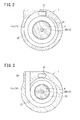
FIG. 2 is an arrow sectional view from a II-II direction inFIG. 1 according to the compressor of embodiment. -
FIG. 3 is an arrow sectional view from a III-III direction inFIG. 1 according to the compressor of embodiment. -
FIG. 4 is a sectional view from the direction same as the direction inFIG. 2 according to the compressor of embodiment. -
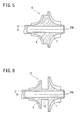
FIG. 5 is a sectional view of the first impeller and the second impeller according to the compressor ofVariation 1. -
FIG. 6 is a sectional view of the first impeller and the second impeller according to the compressor of Variation 2. - An embodiment embodying the present invention is explained below with reference to the drawings. A compressor in the embodiment is a motor-driven turbo compressor for a vehicle. The compressor is mounted on a vehicle and configures a refrigeration circuit of an air conditioner for a vehicle.
- As shown in
FIG. 1 , the compressor in the embodiment includes ahousing 1, arotating shaft 3, anelectric motor 5, afirst impeller 7, and asecond impeller 9. - The
housing 1 includes afront housing 11, anend plate 13, and arear housing 15. - The
front housing 11 consists of a firstfront housing 11a, a secondfront housing 11b, a thirdfront housing 11c, and a fourthfront housing 11d. In thefront housing 11, the firstfront housing 11a, the secondfront housing 11b, the thirdfront housing 11c, and the fourthfront housing 11d are joined in this order from the front end side toward the rear end side. Thefront housing 11 is formed into a substantially cylindrical shape as a whole. In thefront housing 11, first andsecond impeller chambers second diffusers second discharge chambers motor chamber 29, afirst boss 31, first andsecond suction ports intermediate pressure port 37, and adischarge port 39 are formed. The first andsecond impeller chambers - The
first impeller chamber 17 is formed on the front end side of thefront housing 11. More specifically, the front end side of thefirst impeller chamber 17 is formed in the firstfront housing 11a. The rear end side of thefirst impeller chamber 17 is formed in the secondfront housing 11b. Thefirst impeller chamber 17 is formed in a shape gradually expanding in diameter from the front end side toward the rear end side. - The
second impeller chamber 19 is formed on the rear side of thefirst impeller chamber 17 in thefront housing 11. More specifically, the front end side of thesecond impeller chamber 17 is formed in the secondfront housing 11b. The rear end side of thesecond impeller chamber 17 is formed in the thirdfront housing 11c. Thesecond impeller chamber 19 is smaller in diameter than thefirst impeller chamber 17. Thesecond impeller chamber 19 is formed in a shape gradually contracting in diameter from the front end side toward the rear end side. In the secondfront housing 11b, afirst shaft hole 41a extending in thehousing 1 in the axial direction of therotating shaft 3 is formed. - The
first diffuser 21 is formed on the front end side of the secondfront housing 11b and located in the outer side of thefirst impeller chamber 17 with respect to the radial direction of therotating shaft 3. Thefirst diffuser 21 communicates with thefirst impeller chamber 17 in a largest diameter part of thefirst impeller chamber 17. Thesecond diffuser 23 is formed on the front end side of the thirdfront housing 11c and located in the outer side of thesecond impeller chamber 19 with respect to the radial direction of therotating shaft 3. Thesecond diffuser 23 communicates with thesecond impeller chamber 19 in a largest diameter part of thesecond impeller chamber 19. Thesecond diffuser 23 is formed smaller in diameter than thefirst diffuser 21. - The front end side of the
first discharge chamber 25 is formed in the firstfront housing 11a. The rear end side of thefirst discharge chamber 25 is formed in the secondfront housing 11b. As shown inFIG. 2 , thefirst discharge chamber 25 is located in the outer side of thefirst diffuser 21 with respect to the radial direction of therotating shaft 3 and communicates with thefirst diffuser 21. Consequently, thefirst impeller chamber 17 and thefirst discharge chamber 25 communicate with each other through thefirst diffuser 21. Thefirst discharge chamber 25 is formed into a spiral shape. Thefirst discharge chamber 25 is formed such that a passage sectional area gradually increases. - As shown in
FIG. 1 , the front side of thesecond discharge chamber 27 is formed in the secondfront housing 11b. The rear end side of thesecond discharge chamber 27 is formed in the thirdfront housing 11c. As shown inFIG. 3 , thesecond discharge chamber 27 is located in the outer side of thesecond diffuser 23 with respect to the radial direction of therotating shaft 3 and communicates with thesecond diffuser 23. Consequently, thesecond impeller chamber 19 and thesecond discharge chamber 27 communicate with each other through thesecond diffuser 23. Like thefirst discharge chamber 25, thesecond discharge chamber 27 is formed into a spiral shape. Thesecond discharge chamber 27 is formed such that a passage sectional area gradually increases. - Here, as explained above, the
second impeller chamber 19 and thesecond diffuser 23 are respectively smaller in diameter than thefirst impeller chamber 19 and thefirst diffuser 21. Therefore, as shown inFIG. 4 , thefirst discharge chamber 25 is located in the outer side of thesecond discharge chamber 27 with respect to the radial direction of therotation shaft 3. Further, as shown inFIG. 3 , the outer circumference side of thesecond discharge chamber 27 communicates with thedischarge port 39. Thedischarge port 39 extends in the radial direction of thehousing 1. - As shown in
FIG. 1 , themotor chamber 29 is formed in the fourthfront housing 11d. Consequently, in thefront housing 11, thefirst impeller chamber 17, thesecond impeller chamber 19, and themotor chamber 29 are formed in this order from the front end side toward the rear end side. Themotor chamber 29 extends in the axial direction of thehousing 1 and defined by the fourthfront housing 11d and theend plate 13. - The
first boss 31 is formed on the front end side of themotor chamber 29 in the fourthfront housing 11d and extends toward the rear end side of themotor chamber 29 in the axial direction of thehousing 1. In thefirst boss 31, asecond shaft hole 41b extending in the axial direction of thehousing 1 is formed. In thesecond shaft hole 41b, a first radial foil bearing 43a is provided. - The
first suction port 33 is formed on the front end side of the firstfront housing 11a. That is, thefirst suction port 33 is located on the front end side of thehousing 1. Thefirst suction port 33 extends in the axial direction of thehousing 1. The front end side of thefirst suction port 33 opens on the front end face of the firstfront housing 11a. The rear end side of thefirst suction port 33 communicates with thefirst impeller chamber 17. - The
second suction port 35 is formed to extend across the rear end side of the thirdfront housing 11c and the front end side of the fourthfront housing 11d. The rear end side of thesecond suction port 35 communicates with themotor chamber 29 on the front end side of thefirst boss 31. On the other hand, the front end side of thesecond suction port 35 communicates with thesecond impeller chamber 19. Further, thesecond suction port 35 communicates with thesecond shaft hole 41b. Themotor chamber 29, thesecond shaft hole 41b, and thesecond impeller chamber 19 communicate with one another through thesecond suction port 35. - As shown in
FIG. 1 , theintermediate pressure port 37 is located on the outer side of thesecond discharge chamber 27 with respect to the radial direction of therotating shaft 3. Theintermediate pressure port 37 is formed to extend across the second to fourthfront housings 11b to 11d in the axial direction of thehousing 1. As shown inFIG. 2 , in the secondfront housing 11b, the front end side of theintermediate pressure port 37 communicates with the outer circumference side of thefirst discharge chamber 25. On the other hand, as shown inFIG. 1 , in the fourthfront housing 11d, the rear end side of theintermediate pressure port 37 communicates with themotor chamber 29. Consequently, thefirst discharge chamber 25 and themotor chamber 29 communicate with each other in the axial direction through theintermediate pressure port 37. Further, as shown inFIG. 4 , in thefront housing 11, theintermediate pressure port 37 and thedischarge port 39 are formed in positions shifted in the radial direction. - The
end plate 13 is joined to the rear end of the fourthfront housing 11d, that is, the rear end of thefront housing 11. The rear end of themotor chamber 29 is defined by theend plate 13. In theend plate 13, asecond boss 45 extending toward themotor chamber 29 side in the axial direction of thehousing 1 is formed. In thesecond boss 45, athird shaft hole 41c extending in the axial direction of thehousing 1 is formed. In thethird shaft hole 41c, a second radial foil bearing 43b is provided. - The
rear housing 15 is located behind thehousing 1 and joined to theend plate 13. That is, therear housing 15 sandwiches theend plate 13 in conjunction with thefront housing 11. In therear housing 15, first and secondthrust foil bearings support plate 49 are provided. The first thrust foil bearing 47a is located on the front end side of thesupport plate 49 and sandwiched by theend plate 13 and thesupport plate 49. The second thrust foil bearing 47b is located on the rear end side of thesupport plate 49 and sandwiched by thesupport plate 49 and therear housing 15. - The
rotating shaft 3 includes a rotating shaftmain body 30a, a firstsmall diameter portion 30b located on the front end side of the rotating shaftmain body 30a, and a secondsmall diameter portion 30c located on the rear end side of the rotating shaft main body 30. The rotating shaftmain body 30a is formed in a largest diameter in therotating shaft 3. On the other hand, both of the first and secondsmall diameter portions main body 30a. The firstsmall diameter portion 30b is formed in diameter smaller than the secondsmall diameter portion 30c. - The
rotating shaft 3 is inserted through thehousing 1 and is capable of rotating in thehousing 1. Specifically, the front end side of the rotating shaftmain body 30a is inserted through thesecond shaft hole 41b and rotatably supported by the first radial foil bearing 43a. On the other hand, the rear end side of the rotating shaftmain body 30a is inserted through thethird shaft hole 41c and rotatably supported by the second radial foil bearing 43b. Further, the firstsmall diameter portion 30b is inserted through thefirst shaft hole 41a. The rear end side of the firstsmall diameter portion 30b is located in thesecond suction port 35. That is, a part of therotating shaft 3 is exposed in thesecond suction port 35. The secondsmall diameter portion 30c is inserted through thesupport plate 49 in therear housing 15. Consequently, the secondsmall diameter portion 30c and by extension, therotating shaft 3 are supported by the first and secondthrust foil bearings support plate 49. - The
electric motor 5 is provided in themotor chamber 29. Theelectric motor 5 consists of astator 5a and arotor 5b. Thestator 5a is fixed to the inner wall of themotor chamber 29. Thestator 5a is electrically connected to a not-shown battery. Therotor 5b is located on the inner side of thestator 5a with respect to the radial direction of therotating shaft 3. In themotor chamber 29, therotor 5b is arranged between thefirst boss 31 and thesecond boss 45. Therotor 5b is fixed to the rotating shaftmain body 30a. Consequently, therotor 5b is capable of rotating integrally with therotating shaft 3 in thestator 5a. - The
first impeller 7 is press-fitted into the front end side of the firstsmall diameter portion 30b and provided in thefirst impeller chamber 17. Consequently, thefirst impeller 7 is capable of rotating in thefirst impeller chamber 17 according to the rotation of therotating shaft 3. Thefirst impeller 7 is formed in diameter smaller than the inner diameter of the motor chamber29. Thefirst impeller 7 is formed in a shape gradually expanding in diameter from the front end side toward the rear end side. The rear end side of thefirst impeller 7 is formed as alarge diameter portion 7a. Further, a plurality ofblades 70 are provided at a predetermined interval on the surface of thefirst impeller 7. - The
second impeller 9 is press-fitted into the rear end side of the firstsmall diameter portion 30b and provided in thesecond impeller chamber 19. Consequently, thesecond impeller 9 is capable of rotating in thesecond impeller chamber 19 according to the rotation of therotating shaft 3. Thesecond impeller 9 is also formed in diameter smaller than the inner diameter of the motor chamber29. Further, thesecond impeller 9 is formed similar to thefirst impeller 7 and is formed to have size of about 70% to 90% of the size of thefirst impeller 7. Thesecond impeller 9 is formed in a shape gradually contracting in diameter from the front end side toward the rear end side. Thesecond impeller 9 is provided on the firstsmall diameter portion 30b such that alarge diameter portion 9a on the front end side is located on the front end side of thefront housing 11. Consequently, in the compressor, in thefront housing 11, thefirst impeller 7 and thesecond impeller 9 are disposed in a direction in which the rear sides of thefirst impeller 7 and thesecond impeller 9 face each other. Further, a plurality of blades 90 are provided at a predetermined interval on the surface of thesecond impeller 9. - In the compressor, a
pipe 201 linked to acondenser 101 is connected to thedischarge port 39. Thecondenser 101 is connected to anevaporator 103 via apipe 202 and anexpansion valve 102. Theevaporator 103 is connected to thefirst suction port 33 through apipe 203. A refrigeration circuit of an air-conditioning apparatus for a vehicle is configured by the compressor, thecondenser 101, theexpansion valve 102, theevaporator 103, and the like. - In the compressor configured as explained above, the
stator 5a rotate therotor 5b by electricity theelectric motor 5. Consequently, therotating shaft 3 is driven to rotate around a rotational axis O in thehousing 1. Therefore, thefirst impeller 7 rotates in thefirst impeller chamber 17. Thesecond impeller 9 rotates in thesecond impeller chamber 19. - Further, a low-pressure refrigerant that passes through the
evaporator 103 is sucked into thefirst suction port 33 through thepipe 203 and reaches the inside of thefirst impeller chamber 17. Thefirst impeller 7 rotating in thefirst impeller chamber 17 increases kinetic energy of the refrigerant in thefirst impeller chamber 17. Thereafter, thefirst impeller 7 converts the kinetic energy of the refrigerant into pressure energy through thefirst diffuser 21, and compresses the refrigerant, and discharges the compressed refrigerant to thefirst discharge chamber 25. Consequently, the pressure of the refrigerant in thefirst discharge chamber 25 changes to an intermediate pressure. The refrigerant having the intermediate pressure circulates from thefirst discharge chamber 25 to theintermediate pressure port 37 and flows into themotor chamber 29 as indicated by a solid line arrow in theFIG. 1 . - The refrigerant flown into the
motor chamber 29 is sucked from thesecond suction port 35 into thesecond impeller chamber 19 as indicated by a solid line arrow in theFIG. 1 . In this case, the refrigerant circulating through thesecond suction port 35 is sucked into thesecond impeller chamber 19 while coming into contact with the firstsmall diameter portion 30b of therotating shaft 3. Thesecond impeller 9 rotating in thesecond impeller chamber 19 increases kinetic energy of the refrigerant in thesecond impeller chamber 19. Thereafter, thesecond impeller 9 converts the kinetic energy of the refrigerant into pressure energy through thesecond diffuser 23, and compresses the refrigerant, and discharges the compressed refrigerant to thesecond discharge chamber 27. In this way, in the compressor, the refrigerant sucked from thefirst suction port 33 is compressed in two stages. - In the compressor, the
first impeller 7, thesecond impeller 9, and theelectric motor 5 are arranged in this order in the axial direction of therotating shaft 3. Consequently, in the compressor, thefirst impeller chamber 17, thesecond impeller chamber 19, and themotor chamber 29 are formed in this order in the axial direction from the front end side toward the rear end side with respect to thefront housing 11. In the compressor, theintermediate pressure port 37 is formed in thefront housing 11 and located on the outer side of thesecond discharge chamber 27 with respect to the radial direction of therotating shaft 3. Thefirst discharge chamber 25 and themotor chamber 29 communicate with each other in the axial direction of thefront housing 11 through theintermediate pressure port 37. Consequently, in the compressor, in thefront housing 11, it is possible to guide the refrigerant having the intermediate pressure in thefirst discharge chamber 25 to themotor chamber 29 through theintermediate pressure port 37. Therefore, in the compressor, it is possible to cool theelectric motor 5 that generates heat during actuation by the refrigerant having the intermediate pressure. - In the compressor, the
intermediate pressure port 37 is formed in the axial direction of thefront housing 11. Therefore, it is possible to suppress an increase in the body diameter of the compressor. Further, since both of the first andsecond impellers second impeller 9 is smaller in diameter than thefirst impeller 7. Thesecond impeller chamber 19 is smaller in size than thefirst impeller chamber 17. Therefore, in the compressor, it is possible to easily cause thefirst discharge chamber 25 and themotor chamber 29 to communicate with each other in the axial direction through theintermediate pressure port 37. - Further, in the compressor, the
second suction port 35 is formed in thefront housing 11. Thefirst discharge chamber 25 and thesecond suction port 35 communicate with each other via theintermediate pressure port 37 and themotor chamber 29. In the compressor, thefirst impeller chamber 17, thesecond impeller chamber 19, and themotor chamber 29 are formed in this order in the axial direction with respect to thefront housing 11. Therefore, in the compressor, in thefront housing 11, thesecond suction port 35 and themotor chamber 29 are arranged close to each other. The rear end side of thesecond suction port 35 opens in themotor chamber 29. Therefore, in the compressor, the refrigerant in themotor chamber 29 is suitably sucked into thesecond suction port 35. Consequently, in the compressor, it is possible to reduce a power loss of the refrigerant circulating from themotor chamber 29 to thesecond impeller chamber 19. - In the compressor, the refrigerant circulating through the
second suction port 35 is sucked into thesecond impeller chamber 19 while coming into contact with the firstsmall diameter portion 30b. Therefore, in the compressor, it is possible to cool therotating shaft 3 by the refrigerant circulating through thesecond suction port 35. - Further, in the compressor, the
first impeller 7 and thesecond impeller 9 are disposed in the direction in which the rear sides of thefirst impeller 7 and thesecond impeller 9 face each other. That is, in the compressor, thefirst impeller 7 and thesecond impeller 9 are arranged with thelarge diameter portions second impeller 9 is formed smaller in diameter than thefirst impeller 7. Therefore, in the compressor, the first thrust force and the second thrust force act to offset each other. The resultant force of the first and second thrust forces decreases. Therefore, in the compressor, it is possible to adopt the first and secondthrust foil bearings - Therefore, with the compressor in the embodiment, a power loss hardly occurs while a reduction in manufacturing costs, a reduction in size, and improvement of durability are surely realized.
- The present invention is explained above according to the embodiment. However, the present invention is not limited to the embodiment. It goes without saying that the present invention can be changed and applied as appropriate without departing from the gist of the present invention.
- For example, although the
first impeller 7 and thesecond impeller 9 in the embodiment are separate members respectively press-fitted into the front end side and the rear end side of the firstsmall diameter portion 30b of therotation shaft 3, thefirst impeller 7 and thesecond impeller 9 may be integrated as an impeller 8 (Variation 1) as shown inFIG. 5 . Further, thefirst impeller 7 and thesecond impeller 9 may be integrated as animpeller 12 using a connector 10 (Variation 2) as shown inFIG. 6 .
Claims (2)
- A motor-driven turbo compressor comprising:a housing in which an impeller chamber and a motor chamber are formed;an electric motor accommodated in the motor chamber;a rotating shaft provided in the housing and driven to rotate by the electric motor;a first impeller and a second impeller accommodated in the impeller chamber and provided on the rotating shaft such that large diameter portions of the first impeller and the second impeller face each other;a first suction port formed in the housing and configured to suck a refrigerant into the impeller chamber;a first discharge chamber formed in the housing and into which the refrigerant supplied to the first impeller via the first suction port and compressed by rotation of the first impeller is discharged;an intermediate pressure port formed in the housing and through which the first discharge chamber communicates with the motor chamber;a second suction port formed in the housing and communicating with the motor chamber; anda second discharge chamber formed in the housing and into which the refrigerant supplied to the second impeller via the second suction port and compressed by rotation of the second impeller is discharged, whereinthe first impeller, the second impeller, and the electric motor are arranged in the axial direction of the rotating shaft in this order,the first impeller and the second impeller are smaller in diameter than the inner diameter of the motor chamber,the second impeller is smaller in diameter than the first impeller,the first discharge chamber is located in the outer side of the first impeller with respect to the radial direction of the rotating shaft,the second discharge chamber is located in the outer side of the second impeller with respect to the radial direction of the rotating shaft, andthe intermediate pressure port is located in the outer side of the second discharge chamber with respect to the radial direction of the rotating shaft.
- The motor-driven turbo compressor according to claim 1, wherein
the impeller chamber includes a second impeller chamber that accommodates the second impeller,
the motor chamber communicates with the second impeller chamber through the second suction port, and
a part of the rotating shaft is exposed in the second suction port.
Applications Claiming Priority (2)
| Application Number | Priority Date | Filing Date | Title |
|---|---|---|---|
| JP2014056130 | 2014-03-19 | ||
| JP2015038154A JP6213500B2 (en) | 2014-03-19 | 2015-02-27 | Electric turbo compressor |
Publications (2)
| Publication Number | Publication Date |
|---|---|
| EP2921708A1 true EP2921708A1 (en) | 2015-09-23 |
| EP2921708B1 EP2921708B1 (en) | 2017-08-30 |
Family
ID=52633146
Family Applications (1)
| Application Number | Title | Priority Date | Filing Date |
|---|---|---|---|
| EP15158392.9A Active EP2921708B1 (en) | 2014-03-19 | 2015-03-10 | Motor-driven turbo compressor |
Country Status (5)
| Country | Link |
|---|---|
| US (1) | US9897091B2 (en) |
| EP (1) | EP2921708B1 (en) |
| JP (1) | JP6213500B2 (en) |
| KR (1) | KR101658728B1 (en) |
| CN (1) | CN104929957B (en) |
Families Citing this family (9)
| Publication number | Priority date | Publication date | Assignee | Title |
|---|---|---|---|---|
| DE102014224757A1 (en) * | 2014-12-03 | 2016-06-09 | Robert Bosch Gmbh | Compressor with a sealing channel |
| US10508590B2 (en) | 2017-02-07 | 2019-12-17 | Kohler Co. | Forced induction engine with electric motor for compressor |
| CN112368481B (en) * | 2018-09-14 | 2023-09-01 | 开利公司 | A compressor configured to control pressure against a magnetic motor thrust bearing |
| CN211573809U (en) * | 2019-08-28 | 2020-09-25 | 青岛经济技术开发区海尔热水器有限公司 | Gas booster and gas equipment |
| EP4027500A1 (en) * | 2021-01-12 | 2022-07-13 | ABB Schweiz AG | An electric machine |
| JP7593275B2 (en) | 2021-09-16 | 2024-12-03 | 株式会社豊田自動織機 | Electric turbo compressor |
| JP7593279B2 (en) | 2021-09-24 | 2024-12-03 | 株式会社豊田自動織機 | Electric turbo compressor |
| JP7622618B2 (en) * | 2021-11-30 | 2025-01-28 | 株式会社豊田自動織機 | Turbo Fluid Machinery |
| JP7754227B1 (en) | 2024-06-06 | 2025-10-15 | 株式会社豊田自動織機 | centrifugal compressor |
Citations (4)
| Publication number | Priority date | Publication date | Assignee | Title |
|---|---|---|---|---|
| JPH0294879A (en) | 1988-09-30 | 1990-04-05 | Toshiba Corp | Multi-screen display device |
| US20070147985A1 (en) * | 2005-12-28 | 2007-06-28 | Ishikawajima-Harima Heavy Industries Co., Ltd. | Turbo compressor |
| EP2258948A2 (en) * | 2009-05-18 | 2010-12-08 | Hamilton Sundstrand Corporation | Improved refrigerant compressor |
| EP2693138A1 (en) * | 2011-03-30 | 2014-02-05 | Kawasaki Jukogyo Kabushiki Kaisha | Centrifugal chiller |
Family Cites Families (8)
| Publication number | Priority date | Publication date | Assignee | Title |
|---|---|---|---|---|
| JPS5817358B2 (en) | 1978-03-07 | 1983-04-06 | 川崎重工業株式会社 | Multi-stage turbo compressor |
| JP3733701B2 (en) * | 1997-06-26 | 2006-01-11 | ダイキン工業株式会社 | Turbo machine |
| JPH11294879A (en) | 1998-02-16 | 1999-10-29 | Daikin Ind Ltd | Refrigerating system |
| JP4396792B2 (en) * | 2000-02-25 | 2010-01-13 | 株式会社Ihi | High-speed motor drive compressor |
| JP4372511B2 (en) * | 2003-10-17 | 2009-11-25 | トヨタ自動車株式会社 | Supercharger with rotating electric machine having a cylindrical member extending between bearings |
| KR20060081791A (en) * | 2005-01-10 | 2006-07-13 | 삼성전자주식회사 | Refrigeration unit with turbo compressor |
| JP4973976B2 (en) * | 2006-02-13 | 2012-07-11 | 株式会社Ihi | Sealed turbo compression refrigerator |
| JP5491818B2 (en) * | 2009-10-01 | 2014-05-14 | 川崎重工業株式会社 | Turbo refrigerator |
-
2015
- 2015-02-27 JP JP2015038154A patent/JP6213500B2/en not_active Expired - Fee Related
- 2015-03-09 US US14/641,980 patent/US9897091B2/en not_active Expired - Fee Related
- 2015-03-10 EP EP15158392.9A patent/EP2921708B1/en active Active
- 2015-03-13 KR KR1020150034914A patent/KR101658728B1/en not_active Expired - Fee Related
- 2015-03-18 CN CN201510119484.6A patent/CN104929957B/en not_active Expired - Fee Related
Patent Citations (4)
| Publication number | Priority date | Publication date | Assignee | Title |
|---|---|---|---|---|
| JPH0294879A (en) | 1988-09-30 | 1990-04-05 | Toshiba Corp | Multi-screen display device |
| US20070147985A1 (en) * | 2005-12-28 | 2007-06-28 | Ishikawajima-Harima Heavy Industries Co., Ltd. | Turbo compressor |
| EP2258948A2 (en) * | 2009-05-18 | 2010-12-08 | Hamilton Sundstrand Corporation | Improved refrigerant compressor |
| EP2693138A1 (en) * | 2011-03-30 | 2014-02-05 | Kawasaki Jukogyo Kabushiki Kaisha | Centrifugal chiller |
Also Published As
| Publication number | Publication date |
|---|---|
| EP2921708B1 (en) | 2017-08-30 |
| KR101658728B1 (en) | 2016-09-21 |
| US9897091B2 (en) | 2018-02-20 |
| JP2015194151A (en) | 2015-11-05 |
| JP6213500B2 (en) | 2017-10-18 |
| KR20150109270A (en) | 2015-10-01 |
| CN104929957B (en) | 2017-04-12 |
| US20150267707A1 (en) | 2015-09-24 |
| CN104929957A (en) | 2015-09-23 |
Similar Documents
| Publication | Publication Date | Title |
|---|---|---|
| EP2921708B1 (en) | Motor-driven turbo compressor | |
| EP2921707A1 (en) | Motor-driven turbo compressor | |
| EP1770243B1 (en) | Scroll fluid machine | |
| EP3401549B1 (en) | Turbo compressor | |
| JP5527349B2 (en) | Vane type compressor | |
| EP2072821A2 (en) | Motor-driven compressor | |
| JP2019535948A (en) | Turbo compressor with separated cooling air passage | |
| US20150267717A1 (en) | Turbo type fluid machine | |
| CN113623242B (en) | Turbo compressor and turbine cooler including the same | |
| KR20180082894A (en) | Turbo compressor | |
| JP2002285994A (en) | Turbo compressor | |
| US20140322048A1 (en) | Motor-driven compressor | |
| KR20120062415A (en) | Scroll compressor | |
| CN111456936A (en) | Scroll compressor having a plurality of scroll members | |
| JP2006283694A (en) | Scroll type fluid machine | |
| JP5633532B2 (en) | Tandem vane compressor | |
| CN112292534A (en) | Centrifugal compressor | |
| CN121263605A (en) | Rotary compressor and refrigerating device | |
| KR100304564B1 (en) | Radial bearing structure for turbo compressor | |
| KR20110138989A (en) | Scroll compressor | |
| KR20010073551A (en) | Structure for cooling motor and shaft in turbo compressor | |
| KR20120090306A (en) | Scroll compressor | |
| US20180030833A1 (en) | Gas compressor | |
| KR19990054842A (en) | Drive shaft support structure of turbo compressor | |
| JP2007077959A (en) | Scroll compressor |
Legal Events
| Date | Code | Title | Description |
|---|---|---|---|
| PUAI | Public reference made under article 153(3) epc to a published international application that has entered the european phase |
Free format text: ORIGINAL CODE: 0009012 |
|
| 17P | Request for examination filed |
Effective date: 20150310 |
|
| AK | Designated contracting states |
Kind code of ref document: A1 Designated state(s): AL AT BE BG CH CY CZ DE DK EE ES FI FR GB GR HR HU IE IS IT LI LT LU LV MC MK MT NL NO PL PT RO RS SE SI SK SM TR |
|
| AX | Request for extension of the european patent |
Extension state: BA ME |
|
| GRAP | Despatch of communication of intention to grant a patent |
Free format text: ORIGINAL CODE: EPIDOSNIGR1 |
|
| INTG | Intention to grant announced |
Effective date: 20170419 |
|
| GRAS | Grant fee paid |
Free format text: ORIGINAL CODE: EPIDOSNIGR3 |
|
| GRAA | (expected) grant |
Free format text: ORIGINAL CODE: 0009210 |
|
| AK | Designated contracting states |
Kind code of ref document: B1 Designated state(s): AL AT BE BG CH CY CZ DE DK EE ES FI FR GB GR HR HU IE IS IT LI LT LU LV MC MK MT NL NO PL PT RO RS SE SI SK SM TR |
|
| AX | Request for extension of the european patent |
Extension state: BA ME |
|
| REG | Reference to a national code |
Ref country code: GB Ref legal event code: FG4D |
|
| REG | Reference to a national code |
Ref country code: CH Ref legal event code: EP |
|
| REG | Reference to a national code |
Ref country code: AT Ref legal event code: REF Ref document number: 923840 Country of ref document: AT Kind code of ref document: T Effective date: 20170915 |
|
| REG | Reference to a national code |
Ref country code: IE Ref legal event code: FG4D |
|
| REG | Reference to a national code |
Ref country code: DE Ref legal event code: R096 Ref document number: 602015004358 Country of ref document: DE |
|
| REG | Reference to a national code |
Ref country code: NL Ref legal event code: MP Effective date: 20170830 |
|
| REG | Reference to a national code |
Ref country code: LT Ref legal event code: MG4D |
|
| REG | Reference to a national code |
Ref country code: AT Ref legal event code: MK05 Ref document number: 923840 Country of ref document: AT Kind code of ref document: T Effective date: 20170830 |
|
| PG25 | Lapsed in a contracting state [announced via postgrant information from national office to epo] |
Ref country code: LT Free format text: LAPSE BECAUSE OF FAILURE TO SUBMIT A TRANSLATION OF THE DESCRIPTION OR TO PAY THE FEE WITHIN THE PRESCRIBED TIME-LIMIT Effective date: 20170830 Ref country code: FI Free format text: LAPSE BECAUSE OF FAILURE TO SUBMIT A TRANSLATION OF THE DESCRIPTION OR TO PAY THE FEE WITHIN THE PRESCRIBED TIME-LIMIT Effective date: 20170830 Ref country code: SE Free format text: LAPSE BECAUSE OF FAILURE TO SUBMIT A TRANSLATION OF THE DESCRIPTION OR TO PAY THE FEE WITHIN THE PRESCRIBED TIME-LIMIT Effective date: 20170830 Ref country code: NO Free format text: LAPSE BECAUSE OF FAILURE TO SUBMIT A TRANSLATION OF THE DESCRIPTION OR TO PAY THE FEE WITHIN THE PRESCRIBED TIME-LIMIT Effective date: 20171130 Ref country code: HR Free format text: LAPSE BECAUSE OF FAILURE TO SUBMIT A TRANSLATION OF THE DESCRIPTION OR TO PAY THE FEE WITHIN THE PRESCRIBED TIME-LIMIT Effective date: 20170830 Ref country code: AT Free format text: LAPSE BECAUSE OF FAILURE TO SUBMIT A TRANSLATION OF THE DESCRIPTION OR TO PAY THE FEE WITHIN THE PRESCRIBED TIME-LIMIT Effective date: 20170830 |
|
| PG25 | Lapsed in a contracting state [announced via postgrant information from national office to epo] |
Ref country code: BG Free format text: LAPSE BECAUSE OF FAILURE TO SUBMIT A TRANSLATION OF THE DESCRIPTION OR TO PAY THE FEE WITHIN THE PRESCRIBED TIME-LIMIT Effective date: 20171130 Ref country code: IS Free format text: LAPSE BECAUSE OF FAILURE TO SUBMIT A TRANSLATION OF THE DESCRIPTION OR TO PAY THE FEE WITHIN THE PRESCRIBED TIME-LIMIT Effective date: 20171230 Ref country code: GR Free format text: LAPSE BECAUSE OF FAILURE TO SUBMIT A TRANSLATION OF THE DESCRIPTION OR TO PAY THE FEE WITHIN THE PRESCRIBED TIME-LIMIT Effective date: 20171201 Ref country code: RS Free format text: LAPSE BECAUSE OF FAILURE TO SUBMIT A TRANSLATION OF THE DESCRIPTION OR TO PAY THE FEE WITHIN THE PRESCRIBED TIME-LIMIT Effective date: 20170830 Ref country code: ES Free format text: LAPSE BECAUSE OF FAILURE TO SUBMIT A TRANSLATION OF THE DESCRIPTION OR TO PAY THE FEE WITHIN THE PRESCRIBED TIME-LIMIT Effective date: 20170830 Ref country code: LV Free format text: LAPSE BECAUSE OF FAILURE TO SUBMIT A TRANSLATION OF THE DESCRIPTION OR TO PAY THE FEE WITHIN THE PRESCRIBED TIME-LIMIT Effective date: 20170830 |
|
| PG25 | Lapsed in a contracting state [announced via postgrant information from national office to epo] |
Ref country code: NL Free format text: LAPSE BECAUSE OF FAILURE TO SUBMIT A TRANSLATION OF THE DESCRIPTION OR TO PAY THE FEE WITHIN THE PRESCRIBED TIME-LIMIT Effective date: 20170830 |
|
| PG25 | Lapsed in a contracting state [announced via postgrant information from national office to epo] |
Ref country code: PL Free format text: LAPSE BECAUSE OF FAILURE TO SUBMIT A TRANSLATION OF THE DESCRIPTION OR TO PAY THE FEE WITHIN THE PRESCRIBED TIME-LIMIT Effective date: 20170830 Ref country code: RO Free format text: LAPSE BECAUSE OF FAILURE TO SUBMIT A TRANSLATION OF THE DESCRIPTION OR TO PAY THE FEE WITHIN THE PRESCRIBED TIME-LIMIT Effective date: 20170830 Ref country code: DK Free format text: LAPSE BECAUSE OF FAILURE TO SUBMIT A TRANSLATION OF THE DESCRIPTION OR TO PAY THE FEE WITHIN THE PRESCRIBED TIME-LIMIT Effective date: 20170830 Ref country code: CZ Free format text: LAPSE BECAUSE OF FAILURE TO SUBMIT A TRANSLATION OF THE DESCRIPTION OR TO PAY THE FEE WITHIN THE PRESCRIBED TIME-LIMIT Effective date: 20170830 |
|
| PG25 | Lapsed in a contracting state [announced via postgrant information from national office to epo] |
Ref country code: EE Free format text: LAPSE BECAUSE OF FAILURE TO SUBMIT A TRANSLATION OF THE DESCRIPTION OR TO PAY THE FEE WITHIN THE PRESCRIBED TIME-LIMIT Effective date: 20170830 Ref country code: SK Free format text: LAPSE BECAUSE OF FAILURE TO SUBMIT A TRANSLATION OF THE DESCRIPTION OR TO PAY THE FEE WITHIN THE PRESCRIBED TIME-LIMIT Effective date: 20170830 Ref country code: SM Free format text: LAPSE BECAUSE OF FAILURE TO SUBMIT A TRANSLATION OF THE DESCRIPTION OR TO PAY THE FEE WITHIN THE PRESCRIBED TIME-LIMIT Effective date: 20170830 Ref country code: IT Free format text: LAPSE BECAUSE OF FAILURE TO SUBMIT A TRANSLATION OF THE DESCRIPTION OR TO PAY THE FEE WITHIN THE PRESCRIBED TIME-LIMIT Effective date: 20170830 |
|
| REG | Reference to a national code |
Ref country code: DE Ref legal event code: R097 Ref document number: 602015004358 Country of ref document: DE |
|
| PLBE | No opposition filed within time limit |
Free format text: ORIGINAL CODE: 0009261 |
|
| STAA | Information on the status of an ep patent application or granted ep patent |
Free format text: STATUS: NO OPPOSITION FILED WITHIN TIME LIMIT |
|
| 26N | No opposition filed |
Effective date: 20180531 |
|
| PG25 | Lapsed in a contracting state [announced via postgrant information from national office to epo] |
Ref country code: SI Free format text: LAPSE BECAUSE OF FAILURE TO SUBMIT A TRANSLATION OF THE DESCRIPTION OR TO PAY THE FEE WITHIN THE PRESCRIBED TIME-LIMIT Effective date: 20170830 |
|
| REG | Reference to a national code |
Ref country code: CH Ref legal event code: PL |
|
| PG25 | Lapsed in a contracting state [announced via postgrant information from national office to epo] |
Ref country code: MC Free format text: LAPSE BECAUSE OF FAILURE TO SUBMIT A TRANSLATION OF THE DESCRIPTION OR TO PAY THE FEE WITHIN THE PRESCRIBED TIME-LIMIT Effective date: 20170830 |
|
| REG | Reference to a national code |
Ref country code: BE Ref legal event code: MM Effective date: 20180331 |
|
| REG | Reference to a national code |
Ref country code: IE Ref legal event code: MM4A |
|
| PG25 | Lapsed in a contracting state [announced via postgrant information from national office to epo] |
Ref country code: LU Free format text: LAPSE BECAUSE OF NON-PAYMENT OF DUE FEES Effective date: 20180310 |
|
| PG25 | Lapsed in a contracting state [announced via postgrant information from national office to epo] |
Ref country code: IE Free format text: LAPSE BECAUSE OF NON-PAYMENT OF DUE FEES Effective date: 20180310 |
|
| PG25 | Lapsed in a contracting state [announced via postgrant information from national office to epo] |
Ref country code: CH Free format text: LAPSE BECAUSE OF NON-PAYMENT OF DUE FEES Effective date: 20180331 Ref country code: LI Free format text: LAPSE BECAUSE OF NON-PAYMENT OF DUE FEES Effective date: 20180331 Ref country code: BE Free format text: LAPSE BECAUSE OF NON-PAYMENT OF DUE FEES Effective date: 20180331 |
|
| PG25 | Lapsed in a contracting state [announced via postgrant information from national office to epo] |
Ref country code: FR Free format text: LAPSE BECAUSE OF NON-PAYMENT OF DUE FEES Effective date: 20180331 |
|
| GBPC | Gb: european patent ceased through non-payment of renewal fee |
Effective date: 20190310 |
|
| PG25 | Lapsed in a contracting state [announced via postgrant information from national office to epo] |
Ref country code: GB Free format text: LAPSE BECAUSE OF NON-PAYMENT OF DUE FEES Effective date: 20190310 Ref country code: MT Free format text: LAPSE BECAUSE OF NON-PAYMENT OF DUE FEES Effective date: 20180310 |
|
| PG25 | Lapsed in a contracting state [announced via postgrant information from national office to epo] |
Ref country code: TR Free format text: LAPSE BECAUSE OF FAILURE TO SUBMIT A TRANSLATION OF THE DESCRIPTION OR TO PAY THE FEE WITHIN THE PRESCRIBED TIME-LIMIT Effective date: 20170830 |
|
| PG25 | Lapsed in a contracting state [announced via postgrant information from national office to epo] |
Ref country code: PT Free format text: LAPSE BECAUSE OF FAILURE TO SUBMIT A TRANSLATION OF THE DESCRIPTION OR TO PAY THE FEE WITHIN THE PRESCRIBED TIME-LIMIT Effective date: 20170830 |
|
| PG25 | Lapsed in a contracting state [announced via postgrant information from national office to epo] |
Ref country code: HU Free format text: LAPSE BECAUSE OF FAILURE TO SUBMIT A TRANSLATION OF THE DESCRIPTION OR TO PAY THE FEE WITHIN THE PRESCRIBED TIME-LIMIT; INVALID AB INITIO Effective date: 20150310 Ref country code: CY Free format text: LAPSE BECAUSE OF FAILURE TO SUBMIT A TRANSLATION OF THE DESCRIPTION OR TO PAY THE FEE WITHIN THE PRESCRIBED TIME-LIMIT Effective date: 20170830 Ref country code: MK Free format text: LAPSE BECAUSE OF NON-PAYMENT OF DUE FEES Effective date: 20170830 |
|
| PG25 | Lapsed in a contracting state [announced via postgrant information from national office to epo] |
Ref country code: AL Free format text: LAPSE BECAUSE OF FAILURE TO SUBMIT A TRANSLATION OF THE DESCRIPTION OR TO PAY THE FEE WITHIN THE PRESCRIBED TIME-LIMIT Effective date: 20170830 |
|
| PGFP | Annual fee paid to national office [announced via postgrant information from national office to epo] |
Ref country code: DE Payment date: 20220203 Year of fee payment: 8 |
|
| REG | Reference to a national code |
Ref country code: DE Ref legal event code: R119 Ref document number: 602015004358 Country of ref document: DE |
|
| PG25 | Lapsed in a contracting state [announced via postgrant information from national office to epo] |
Ref country code: DE Free format text: LAPSE BECAUSE OF NON-PAYMENT OF DUE FEES Effective date: 20231003 |