EP2258948A2 - Improved refrigerant compressor - Google Patents
Improved refrigerant compressor Download PDFInfo
- Publication number
- EP2258948A2 EP2258948A2 EP10250947A EP10250947A EP2258948A2 EP 2258948 A2 EP2258948 A2 EP 2258948A2 EP 10250947 A EP10250947 A EP 10250947A EP 10250947 A EP10250947 A EP 10250947A EP 2258948 A2 EP2258948 A2 EP 2258948A2
- Authority
- EP
- European Patent Office
- Prior art keywords
- compressor
- housing
- refrigerant
- impeller
- refrigerant flow
- Prior art date
- Legal status (The legal status is an assumption and is not a legal conclusion. Google has not performed a legal analysis and makes no representation as to the accuracy of the status listed.)
- Withdrawn
Links
Images


Classifications
-
- F—MECHANICAL ENGINEERING; LIGHTING; HEATING; WEAPONS; BLASTING
- F04—POSITIVE - DISPLACEMENT MACHINES FOR LIQUIDS; PUMPS FOR LIQUIDS OR ELASTIC FLUIDS
- F04D—NON-POSITIVE-DISPLACEMENT PUMPS
- F04D25/00—Pumping installations or systems
- F04D25/02—Units comprising pumps and their driving means
- F04D25/06—Units comprising pumps and their driving means the pump being electrically driven
-
- F—MECHANICAL ENGINEERING; LIGHTING; HEATING; WEAPONS; BLASTING
- F04—POSITIVE - DISPLACEMENT MACHINES FOR LIQUIDS; PUMPS FOR LIQUIDS OR ELASTIC FLUIDS
- F04D—NON-POSITIVE-DISPLACEMENT PUMPS
- F04D17/00—Radial-flow pumps, e.g. centrifugal pumps; Helico-centrifugal pumps
- F04D17/08—Centrifugal pumps
- F04D17/10—Centrifugal pumps for compressing or evacuating
- F04D17/12—Multi-stage pumps
-
- F—MECHANICAL ENGINEERING; LIGHTING; HEATING; WEAPONS; BLASTING
- F04—POSITIVE - DISPLACEMENT MACHINES FOR LIQUIDS; PUMPS FOR LIQUIDS OR ELASTIC FLUIDS
- F04D—NON-POSITIVE-DISPLACEMENT PUMPS
- F04D29/00—Details, component parts, or accessories
- F04D29/58—Cooling; Heating; Diminishing heat transfer
- F04D29/5806—Cooling the drive system
Definitions
- the subject matter disclosed herein relates to compressors. More specifically, the subject disclosure relates to fluid flow in a compressor.
- Compressors are utilized in many different applications, for example, in vapor cycle refrigeration systems.
- a circulating refrigerant flows through four components: a compressor, a condenser, an expansion valve and an evaporator.
- the refrigerant in a vapor state, is compressed and heated in the compressor, then is condensed into a liquid in the condenser by a heat sink.
- the liquid refrigerant then undergoes a rapid reduction in pressure when routed through the expansion valve.
- the rapid expansion causes an evaporation of at least a portion of the refrigerant resulting in a lowering of the temperature of the refrigerant.
- the liquid portion of the refrigerant is then evaporated in the evaporator and heat is absorbed from a fluid, typically air for example, flowing through the evaporator.
- Compressor power is typically provided by an electric motor.
- the compressor portion powered by an electrical motor, typically includes one or more compressor impellers rotably located about a rotor shaft in a compressor housing assembly.
- the refrigerant passes through the impellers in succession, increasing the pressure and the temperature of the refrigerant.
- impellers are located at opposing ends of the compressor to improve rotor dynamics conditions.
- one or more conduits are provided external to the housing assembly and connected at one or more ports. The refrigerant passes through a first impeller and exits the housing through the one or more ports into a first end of the one or more conduits and reenters the housing via ports near a second impeller and passes through the second impeller.
- the refrigerant is passed through a heat exchanger to remove heat generated from the compression via the first impeller.
- a motor stator portion is located between the first and second impeller and is subjected to the heat due to the inefficiency in converting electric power to mechanical power.
- cooling jackets are often added around the exterior of the stator portion.
- the porting and connections to external conduits introduce additional components to the system and add weight. Further, the connections introduce a potential source of leakage which negatively impacts the performance and efficiency of the compressor and the refrigeration system.
- a compressor for a refrigeration system includes a housing and at least two compressor impellers capable of compressing a refrigerant flow through the compressor. At least one refrigerant pathway is located inboard of an outer surface of the housing and extends from a first impeller of at least one impeller.
- a refrigeration system includes a condenser, an expansion valve in fluid communication with the condenser and an evaporator in fluid communication with the expansion valve.
- the system further includes a compressor in fluid communication with the condenser and the evaporator.
- the compressor includes a housing and at least one compressor impeller located in the housing capable of compressing a refrigerant flow through the compressor. At least one refrigerant pathway is located inboard of an outer surface of the housing and extends from a first impeller of the at least one impeller.
- a method of flowing refrigerant through a compressor includes urging a refrigerant flow past a first compressor impeller of at least one compressor impeller located in a compressor housing and urging the refrigerant flow through at least one refrigerant pathway extending from the first impeller.
- the at least one refrigerant pathway is located inboard of an outer surface of the compressor housing.
- FIG. 1 is a schematic view of an embodiment of a vapor cycle refrigeration system
- FIG. 2 is a cross-sectional view of an embodiment of a compressor
- FIG. 3 is a perspective view of an embodiment of a stator section for a compressor.
- FIG. 4 is a cross-sectional view of another embodiment of a compressor.
- FIG. 1 Shown in FIG. 1 is schematic view of an embodiment of a vapor cycle refrigeration system 10.
- the system 10 includes a compressor 12 in which a circulating refrigerant flow 14 in a vapor state is compressed and heated.
- the refrigerant flow 14 is urged to a condenser 16 where the refrigerant flow 14 is condensed into a liquid state.
- the refrigerant flow 14 is rapidly depressurized in an expansion valve 18 which reduces the temperature of the refrigerant flow 14.
- the cooled refrigerant flow 14 is then routed to an evaporator 20 where it is evaporated and absorbs heat from a fluid flowing across the evaporator 20 by, for example, air as propelled by a fan 22.
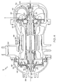
- FIG. 2 illustrates an embodiment of the compressor 12.
- the compressor 12 includes two compressor impellers, a first impeller 24 and a second impeller 26 axially secured to a shaft 28.
- the first compressor impeller 24 and/or the second compressor impeller 26 are centrifugal rotors.
- the first compressor impeller 24 and the second compressor impeller 26 are disposed at substantially opposing ends of the shaft 28 for improved rotor dynamic characteristics. It is to be appreciated that other configurations, for example, ones where the first impeller 24 and second impeller 26 are disposed substantially adjacent on the shaft 28, are contemplated within the scope of the present disclosure. Further, while the quantity of compressor impellers illustrated in FIG.
- compressor impellers 24 and 26 are disposed in a housing set 30, which in some embodiments comprises a first housing portion 32 and a second housing portion 34.
- the first compressor impeller 24 is disposed in the first housing portion 32 and the second compressor impeller 26 is disposed in the second housing portion 34.
- the first compressor impeller 24 and the second compressor impeller 26 at least one motor stator section 36 is disposed in the housing 30.
- the first housing portion 32 includes at least one input port 38 for input of the refrigerant flow 14 from the evaporator 20.
- the refrigerant flow 14 is urged to the first compressor impeller 24 by rotation of the first compressor impeller 24.
- the first compressor impeller 24 accelerates the refrigerant flow 14 through a first rotor channel 40 between the first compressor impeller 24 and a first housing member 42.
- the first rotor channel 40 gets progressively narrower along its length to increase the pressure of the refrigerant flow 14.
- the refrigerant flow 14 in some embodiments is urged substantially radially outwardly toward at least one first housing passage 44 disposed between an inner surface 46 and an outer surface 48 of the first housing portion 32.
- the at least one first housing passage 44 extends through the first housing portion 32 from the first rotor channel 40 to the motor stator section 36.
- the refrigerant flow 14 is urged therethrough toward the motor stator section 36.
- the motor stator section 36 includes a plurality of motor stator members 50, extending substantially from a first motor stator end 52 to a second motor stator end 54 of the motor stator section 36. At least one stator slot 56 is disposed between adjacent motor stator members 50 of the plurality of motor stator members 50. A plurality of stator passages 58 are formed between the at least one stator slot 56, at an outer surface 60 of the motor stator section 36 and the inner surface 46 of the housing 30.
- the plurality of stator passages 58 are disposed and configured to be in connected to the at least one first housing passage 44 so that the refrigerant flow 14 is urged from the at least one first housing passage 44 through the plurality of stator passages 58 from the first motor stator end 52 to the second motor stator end 54 of the motor stator section 36 toward the second housing section 34.
- Flowing the refrigerant flow 14 through the plurality of stator passages 58 provides cooling to the motor stator section 36 so that, in some embodiments, additional cooling of the motor stator section 36 via, for example, cooling jackets, is not needed.
- the second housing section 34 includes at least one second housing passage 62.
- the at least one second housing passage 62 is disposed internal to the second housing section 34 between the inner surface 46 and the outer surface 48 of the second housing section 34, and is configured such that the refrigerant flow 14 is urged from the plurality of stator passages 58 into the at least one second housing passage 62.
- the refrigerant flow 14 flows through the at least one second housing passage 62 toward the second compressor impeller 26.
- the second compressor impeller 26 accelerates the refrigerant flow 14 through a second rotor channel 64 between the second compressor impeller 26 and a second housing member 66.
- the second rotor channel 64 gets progressively narrower along its length to increase the pressure of the refrigerant flow 14.
- the refrigerant flow 14 exits the compressor 12 and flows toward the condenser 16. It is to be appreciated, however, that in other embodiments in which the compressor 12 comprises additional compressor impellers, the flow of refrigerant 14 continues to subsequent impellers in the compressor 12 in a substantially similar manner to that described above. As shown in FIG. 2 , in some embodiments the second housing passage 62 carries the refrigerant flow 14 to be urged past the second compressor impeller 26 at a first side 68 of the second compressor impeller 26 disposed closest to the first compressor impeller 24. In other embodiments as, for example, shown in FIG.
- the second compressor impeller 26 is disposed such that the first side 68 is disposed farthest from the first compressor impeller 24.
- the second housing passage 62 is configured and disposed such that the refrigerant flow 14 flows past the second compressor impeller 26 beginning at the first side 68, located farthest from the first compressor impeller 24.
Abstract
Description
- The subject matter disclosed herein relates to compressors. More specifically, the subject disclosure relates to fluid flow in a compressor.
- Compressors are utilized in many different applications, for example, in vapor cycle refrigeration systems. In a typical vapor cycle refrigeration system, a circulating refrigerant flows through four components: a compressor, a condenser, an expansion valve and an evaporator. The refrigerant, in a vapor state, is compressed and heated in the compressor, then is condensed into a liquid in the condenser by a heat sink. The liquid refrigerant then undergoes a rapid reduction in pressure when routed through the expansion valve. The rapid expansion causes an evaporation of at least a portion of the refrigerant resulting in a lowering of the temperature of the refrigerant. The liquid portion of the refrigerant is then evaporated in the evaporator and heat is absorbed from a fluid, typically air for example, flowing through the evaporator. Compressor power is typically provided by an electric motor.
- The compressor portion, powered by an electrical motor, typically includes one or more compressor impellers rotably located about a rotor shaft in a compressor housing assembly. The refrigerant passes through the impellers in succession, increasing the pressure and the temperature of the refrigerant. In many compressors, impellers are located at opposing ends of the compressor to improve rotor dynamics conditions. To convey the refrigerant between the impellers, one or more conduits are provided external to the housing assembly and connected at one or more ports. The refrigerant passes through a first impeller and exits the housing through the one or more ports into a first end of the one or more conduits and reenters the housing via ports near a second impeller and passes through the second impeller. In some systems, during the flow along the one or more conduits, the refrigerant is passed through a heat exchanger to remove heat generated from the compression via the first impeller. Additionally, a motor stator portion is located between the first and second impeller and is subjected to the heat due to the inefficiency in converting electric power to mechanical power. To cool the stator, cooling jackets are often added around the exterior of the stator portion.
- The porting and connections to external conduits introduce additional components to the system and add weight. Further, the connections introduce a potential source of leakage which negatively impacts the performance and efficiency of the compressor and the refrigeration system.
- According to one aspect of the invention, a compressor for a refrigeration system includes a housing and at least two compressor impellers capable of compressing a refrigerant flow through the compressor. At least one refrigerant pathway is located inboard of an outer surface of the housing and extends from a first impeller of at least one impeller.
- According to another aspect of the invention, a refrigeration system includes a condenser, an expansion valve in fluid communication with the condenser and an evaporator in fluid communication with the expansion valve. The system further includes a compressor in fluid communication with the condenser and the evaporator. The compressor includes a housing and at least one compressor impeller located in the housing capable of compressing a refrigerant flow through the compressor. At least one refrigerant pathway is located inboard of an outer surface of the housing and extends from a first impeller of the at least one impeller.
- According to yet another aspect of the invention, a method of flowing refrigerant through a compressor includes urging a refrigerant flow past a first compressor impeller of at least one compressor impeller located in a compressor housing and urging the refrigerant flow through at least one refrigerant pathway extending from the first impeller. The at least one refrigerant pathway is located inboard of an outer surface of the compressor housing.
- These and other advantages and features will become more apparent from the following description taken in conjunction with the drawings.
- The subject matter, which is regarded as the invention, is particularly pointed out and distinctly claimed in the claims at the conclusion of the specification. The foregoing and other features, and advantages of the invention are apparent from the following detailed description taken in conjunction with the accompanying drawings in which:
-
FIG. 1 is a schematic view of an embodiment of a vapor cycle refrigeration system; -
FIG. 2 is a cross-sectional view of an embodiment of a compressor; -
FIG. 3 is a perspective view of an embodiment of a stator section for a compressor; and -
FIG. 4 is a cross-sectional view of another embodiment of a compressor. - The detailed description explains embodiments of the invention, together with advantages and features, by way of example with reference to the drawings.
- Shown in
FIG. 1 is schematic view of an embodiment of a vaporcycle refrigeration system 10. Thesystem 10 includes acompressor 12 in which a circulatingrefrigerant flow 14 in a vapor state is compressed and heated. Therefrigerant flow 14 is urged to acondenser 16 where therefrigerant flow 14 is condensed into a liquid state. Therefrigerant flow 14 is rapidly depressurized in anexpansion valve 18 which reduces the temperature of therefrigerant flow 14. The cooledrefrigerant flow 14 is then routed to anevaporator 20 where it is evaporated and absorbs heat from a fluid flowing across theevaporator 20 by, for example, air as propelled by afan 22. -
FIG. 2 illustrates an embodiment of thecompressor 12. Thecompressor 12 includes two compressor impellers, afirst impeller 24 and asecond impeller 26 axially secured to ashaft 28. In some embodiments, thefirst compressor impeller 24 and/or thesecond compressor impeller 26 are centrifugal rotors. In the embodiment ofFIG. 2 , thefirst compressor impeller 24 and thesecond compressor impeller 26 are disposed at substantially opposing ends of theshaft 28 for improved rotor dynamic characteristics. It is to be appreciated that other configurations, for example, ones where thefirst impeller 24 andsecond impeller 26 are disposed substantially adjacent on theshaft 28, are contemplated within the scope of the present disclosure. Further, while the quantity of compressor impellers illustrated inFIG. 2 is two, it is merely used as an example, and other quantities of compressor impellers, for example, 1, 3 or 4 or more compressor impellers, may be utilized. Thecompressor impellers housing set 30, which in some embodiments comprises afirst housing portion 32 and asecond housing portion 34. In some embodiments, thefirst compressor impeller 24 is disposed in thefirst housing portion 32 and thesecond compressor impeller 26 is disposed in thesecond housing portion 34. Between thefirst compressor impeller 24 and thesecond compressor impeller 26, at least onemotor stator section 36 is disposed in thehousing 30. - The
first housing portion 32 includes at least oneinput port 38 for input of therefrigerant flow 14 from theevaporator 20. Therefrigerant flow 14 is urged to thefirst compressor impeller 24 by rotation of thefirst compressor impeller 24. Thefirst compressor impeller 24 accelerates therefrigerant flow 14 through afirst rotor channel 40 between thefirst compressor impeller 24 and afirst housing member 42. Thefirst rotor channel 40 gets progressively narrower along its length to increase the pressure of therefrigerant flow 14. The refrigerant flow 14 in some embodiments is urged substantially radially outwardly toward at least one first housing passage 44 disposed between aninner surface 46 and anouter surface 48 of thefirst housing portion 32. The at least one first housing passage 44 extends through thefirst housing portion 32 from thefirst rotor channel 40 to themotor stator section 36. Therefrigerant flow 14 is urged therethrough toward themotor stator section 36. - Referring now to
FIG. 3 , themotor stator section 36 includes a plurality ofmotor stator members 50, extending substantially from a firstmotor stator end 52 to a secondmotor stator end 54 of themotor stator section 36. At least onestator slot 56 is disposed between adjacentmotor stator members 50 of the plurality ofmotor stator members 50. A plurality ofstator passages 58 are formed between the at least onestator slot 56, at anouter surface 60 of themotor stator section 36 and theinner surface 46 of thehousing 30. The plurality ofstator passages 58 are disposed and configured to be in connected to the at least one first housing passage 44 so that therefrigerant flow 14 is urged from the at least one first housing passage 44 through the plurality ofstator passages 58 from the firstmotor stator end 52 to the secondmotor stator end 54 of themotor stator section 36 toward thesecond housing section 34. Flowing the refrigerant flow 14 through the plurality ofstator passages 58 provides cooling to themotor stator section 36 so that, in some embodiments, additional cooling of themotor stator section 36 via, for example, cooling jackets, is not needed. - Referring again to
FIG. 2 , thesecond housing section 34 includes at least onesecond housing passage 62. The at least onesecond housing passage 62 is disposed internal to thesecond housing section 34 between theinner surface 46 and theouter surface 48 of thesecond housing section 34, and is configured such that therefrigerant flow 14 is urged from the plurality ofstator passages 58 into the at least onesecond housing passage 62. Therefrigerant flow 14 flows through the at least onesecond housing passage 62 toward thesecond compressor impeller 26. Thesecond compressor impeller 26 accelerates therefrigerant flow 14 through asecond rotor channel 64 between thesecond compressor impeller 26 and asecond housing member 66. Thesecond rotor channel 64 gets progressively narrower along its length to increase the pressure of therefrigerant flow 14. In some embodiments, after being urged past thesecond compressor impeller 26, therefrigerant flow 14 exits thecompressor 12 and flows toward thecondenser 16. It is to be appreciated, however, that in other embodiments in which thecompressor 12 comprises additional compressor impellers, the flow ofrefrigerant 14 continues to subsequent impellers in thecompressor 12 in a substantially similar manner to that described above. As shown inFIG. 2 , in some embodiments thesecond housing passage 62 carries therefrigerant flow 14 to be urged past thesecond compressor impeller 26 at afirst side 68 of thesecond compressor impeller 26 disposed closest to thefirst compressor impeller 24. In other embodiments as, for example, shown inFIG. 4 , thesecond compressor impeller 26 is disposed such that thefirst side 68 is disposed farthest from thefirst compressor impeller 24. In this embodiment, thesecond housing passage 62 is configured and disposed such that therefrigerant flow 14 flows past thesecond compressor impeller 26 beginning at thefirst side 68, located farthest from thefirst compressor impeller 24. - Flowing the
refrigerant flow 14 internally through thecompressor 12 from compressor impeller to compressor impeller, as opposed to externally, eliminates external hardware and connectors which provide opportunities for leakage of therefrigerant flow 14 from thecompressor 12. Further, elimination of parts reduces weight of thecompressor 12. A direct means of cooling themotor stator section 36 is provided, and heat from themotor stator section 36 eliminates liquid-state refrigerant from therefrigerant flow 14, so that the entire flow through thecompressor 12 is in a vapor state. The entirely vapor state improves operational efficiency of any subsequent compressor rotors and of fluid film bearings which are utilized in some embodiments to support the rotating elements. - While the invention has been described in detail in connection with only a limited number of embodiments, it should be readily understood that the invention is not limited to such disclosed embodiments. Rather, the invention can be modified to incorporate any number of variations, alterations, substitutions or equivalent arrangements not heretofore described, but which are commensurate with the scope of the invention. Additionally, while various embodiments of the invention have been described, it is to be understood that aspects of the invention may include only some of the described embodiments. Accordingly, the invention is not to be seen as limited by the foregoing description, but is only limited by the scope of the appended claims.
Claims (13)
- A compressor (12) for a refrigeration system (10) comprising:a housing (30);at least one compressor impeller (24, 26) disposed in the housing (30) capable of compressing a refrigerant flow (14) through the compressor (12); andat least one refrigerant pathway (44, 62) disposed inboard of an outer surface (48) of the housing (30), the refrigerant pathway (44, 62) extending from a first compressor impeller (24) of the at least one compressor impeller (24, 26).
- The compressor (12) of Claim 1 wherein the at least one refrigerant pathway (44, 62) extends from the first compressor impeller (24) to a second compressor impeller (26).
- The compressor (12) of Claim 1 or 2 wherein at least one motor stator section (36) is disposed in the housing (30).
- The compressor (12) of Claims 2 and 3 wherein the at least one motor stator section (36) is disposed between the first compressor impeller (24) and the second compressor impeller (26).
- The compressor (12) of Claim 3 or 4 wherein the at least one refrigerant pathway (44, 62) extends through at least one stator passage (58) defined by an outer surface (60) of the motor stator section (36) and an inner surface (46) of the housing (30).
- The compressor (12) of Claim 5 wherein the at least one refrigerant pathway (14) is capable of cooling the motor stator section (36).
- The compressor (12) of any preceding Claim wherein at least a portion of the at least one refrigerant pathway (14) is disposed between the outer surface (48) of the housing (30) and an inner surface (46) of the housing (30).
- The compressor (12) of any preceding Claim wherein the at least one compressor impeller (24, 26) is a centrifugal rotor.
- A refrigeration system (10) comprising:a condenser (16);an expansion valve (18) in fluid communication with the condenser (16);an evaporator (20) in fluid communication with the expansion valve (18); anda compressor (12) as claimed in any preceding claim in fluid communication with the condenser (16) and the evaporator (20).
- A method of flowing refrigerant through a compressor (12) comprising:urging a refrigerant flow (14) past at least one compressor impeller (24, 26) disposed in a compressor housing (30);urging the refrigerant flow (14) through at least one refrigerant pathway (44, 62) extending from a first compressor impeller (24), the at least one refrigerant pathway (44, 62) being disposed inboard of an outer surface (48) of the compressor housing (30).
- The method of Claim 10 comprising urging the refrigerant flow (14) from the at least one refrigerant pathway (44,62) past a second compressor impeller (26).
- The method of Claim 10 or 11 comprising urging the refrigerant flow (14) through at least one stator passage (58) defined by an outer surface (60) of a motor stator section (36) disposed in the compressor housing (30) and an inner surface (46) of the compressor housing.
- The method of Claim 12 comprising cooling the motor stator section (36) via the refrigerant flow (14) through the at least one stator passage (58).
Applications Claiming Priority (1)
| Application Number | Priority Date | Filing Date | Title |
|---|---|---|---|
| US12/467,706 US8061151B2 (en) | 2009-05-18 | 2009-05-18 | Refrigerant compressor |
Publications (2)
| Publication Number | Publication Date |
|---|---|
| EP2258948A2 true EP2258948A2 (en) | 2010-12-08 |
| EP2258948A3 EP2258948A3 (en) | 2012-10-10 |
Family
ID=42358633
Family Applications (1)
| Application Number | Title | Priority Date | Filing Date |
|---|---|---|---|
| EP10250947A Withdrawn EP2258948A3 (en) | 2009-05-18 | 2010-05-18 | Improved refrigerant compressor |
Country Status (3)
| Country | Link |
|---|---|
| US (1) | US8061151B2 (en) |
| EP (1) | EP2258948A3 (en) |
| JP (1) | JP2010265900A (en) |
Cited By (5)
| Publication number | Priority date | Publication date | Assignee | Title |
|---|---|---|---|---|
| EP2921707A1 (en) * | 2014-03-19 | 2015-09-23 | Kabushiki Kaisha Toyota Jidoshokki | Motor-driven turbo compressor |
| EP2921708A1 (en) * | 2014-03-19 | 2015-09-23 | Kabushiki Kaisha Toyota Jidoshokki | Motor-driven turbo compressor |
| EP2952697A1 (en) * | 2014-06-02 | 2015-12-09 | Hamilton Sundstrand Corporation | Rotary machine heat sink |
| EP3401549A1 (en) * | 2017-05-11 | 2018-11-14 | LG Electronics Inc. | Turbo compressor |
| CN111255695A (en) * | 2020-02-10 | 2020-06-09 | 嘉兴学院 | Screw air compressor |
Families Citing this family (17)
| Publication number | Priority date | Publication date | Assignee | Title |
|---|---|---|---|---|
| US8931304B2 (en) * | 2010-07-20 | 2015-01-13 | Hamilton Sundstrand Corporation | Centrifugal compressor cooling path arrangement |
| GB2524422B (en) | 2013-05-03 | 2016-01-06 | Dyson Technology Ltd | Compressor |
| GB2525543B (en) * | 2013-05-03 | 2016-01-06 | Dyson Technology Ltd | Compressor |
| GB2513663B (en) | 2013-05-03 | 2015-11-04 | Dyson Technology Ltd | Compressor |
| EP3557079A1 (en) * | 2018-04-20 | 2019-10-23 | Belenos Clean Power Holding AG | Heating, ventilation and air conditioning system comprising a fluid compressor |
| EP3557080A1 (en) * | 2018-04-20 | 2019-10-23 | Belenos Clean Power Holding AG | Heat pump comprising a fluid compressor |
| EP3557081A1 (en) * | 2018-04-20 | 2019-10-23 | Belenos Clean Power Holding AG | Fuel cell comprising a fluid compressor |
| EP3557078A1 (en) * | 2018-04-20 | 2019-10-23 | Belenos Clean Power Holding AG | Fluid compressor |
| EP3973193A1 (en) * | 2019-05-23 | 2022-03-30 | Carrier Corporation | Refrigeration system mixed-flow compressor |
| US11143203B2 (en) * | 2019-08-02 | 2021-10-12 | Hamilton Sundstrand Corporation | Motor and bearing cooling paths |
| US11225978B2 (en) * | 2019-08-02 | 2022-01-18 | Hamilton Sundstrand Corporation | Motor and bearing cooling paths |
| US11486618B2 (en) * | 2019-10-11 | 2022-11-01 | Danfoss A/S | Integrated connector for multi-stage compressor |
| KR20210129881A (en) * | 2020-04-21 | 2021-10-29 | 엘지전자 주식회사 | Compressor and Chiller including the same |
| KR20210129962A (en) * | 2020-04-21 | 2021-10-29 | 엘지전자 주식회사 | Compressor and Chiller system having the same |
| KR20210136587A (en) * | 2020-05-08 | 2021-11-17 | 엘지전자 주식회사 | A turbo compressor and a turbo chiller including the same |
| US20230151824A1 (en) * | 2021-11-12 | 2023-05-18 | Carrier Corporation | Multistage compressor with swirl-reducing ribs |
| US20230323886A1 (en) * | 2022-04-11 | 2023-10-12 | Carrier Corporation | Two stage mixed-flow compressor |
Family Cites Families (28)
| Publication number | Priority date | Publication date | Assignee | Title |
|---|---|---|---|---|
| US3554676A (en) * | 1969-02-05 | 1971-01-12 | Loren A Porteous | Vapor compressor |
| JP2605512B2 (en) * | 1991-07-30 | 1997-04-30 | ダイキン工業株式会社 | Compressor and method of manufacturing compressor |
| US5350039A (en) * | 1993-02-25 | 1994-09-27 | Nartron Corporation | Low capacity centrifugal refrigeration compressor |
| US5363674A (en) * | 1993-05-04 | 1994-11-15 | Ecoair Corp. | Zero superheat refrigeration compression system |
| US6450781B1 (en) * | 1996-04-26 | 2002-09-17 | Samjin Co., Ltd. | Centrifugal compressor assembly for a refrigerating system |
| US6064121A (en) * | 1998-02-27 | 2000-05-16 | Hamilton Sundstrand Corporation | Axially compact generator set and refrigeration system employing the same |
| KR100288315B1 (en) * | 1999-03-15 | 2001-04-16 | 김평길 | Two-stage centrifugal compressor |
| JP2000337261A (en) * | 1999-05-26 | 2000-12-05 | Funai Electric Co Ltd | Compressor |
| JP3370046B2 (en) * | 2000-03-30 | 2003-01-27 | 三洋電機株式会社 | Multi-stage compressor |
| US6663044B1 (en) * | 2001-09-20 | 2003-12-16 | Hamilton Sundstrand Corporation | Vapor compression cycle environmental control system |
| US7128540B2 (en) * | 2001-09-27 | 2006-10-31 | Sanyo Electric Co., Ltd. | Refrigeration system having a rotary compressor |
| CA2373905A1 (en) * | 2002-02-28 | 2003-08-28 | Ronald David Conry | Twin centrifugal compressor |
| JP2003254273A (en) * | 2002-03-06 | 2003-09-10 | Sanden Corp | Two-stage compressor for vehicle air conditioning |
| US6631617B1 (en) * | 2002-06-27 | 2003-10-14 | Tecumseh Products Company | Two stage hermetic carbon dioxide compressor |
| KR100498376B1 (en) * | 2002-11-19 | 2005-07-01 | 엘지전자 주식회사 | Scroll compressor and fabrication method for scroll compressor |
| US6637216B1 (en) * | 2003-01-22 | 2003-10-28 | Bristol Compressors, Inc. | Compressor with internal accumulator for use in split compressor |
| DE102004040899A1 (en) * | 2004-08-24 | 2006-03-30 | Schicketanz, Walter, Dr. | Monitoring pumps to detect abnormal operating states, by processing signals from temperature sensors, arranged on pump and triggering countermeasures |
| US7779642B2 (en) * | 2004-12-14 | 2010-08-24 | Lg Electronics Inc. | Air conditioner and driving method thereof |
| KR20060081791A (en) * | 2005-01-10 | 2006-07-13 | 삼성전자주식회사 | Refrigerator apparatus with turbo compressor |
| KR100619768B1 (en) * | 2005-02-03 | 2006-09-11 | 엘지전자 주식회사 | 2-stage reciprocating compressor and refrigerator with this |
| US7213405B2 (en) * | 2005-05-10 | 2007-05-08 | Hussmann Corporation | Two-stage linear compressor |
| US7478539B2 (en) * | 2005-06-24 | 2009-01-20 | Hussmann Corporation | Two-stage linear compressor |
| JPWO2007000815A1 (en) * | 2005-06-29 | 2009-01-22 | 株式会社前川製作所 | Lubricating method for two-stage screw compressor, device and operating method for refrigerating device |
| US7334422B2 (en) * | 2005-11-29 | 2008-02-26 | Hamilton Sundstrand Corporation | Cabin air conditioning system with liquid cooling for power electronics |
| JP4797715B2 (en) * | 2006-03-09 | 2011-10-19 | ダイキン工業株式会社 | Refrigeration equipment |
| US20080019842A1 (en) | 2006-07-21 | 2008-01-24 | Hamilton Sundstrand Corporation | System and method for controlling compressor flow |
| US7901192B2 (en) * | 2007-04-04 | 2011-03-08 | Lg Electronics Inc. | Two stage reciprocating compressor and refrigerator having the same |
| US7758320B2 (en) * | 2007-05-03 | 2010-07-20 | Tank, Inc. | Two-stage hydrodynamic pump and method |
-
2009
- 2009-05-18 US US12/467,706 patent/US8061151B2/en active Active
-
2010
- 2010-05-18 EP EP10250947A patent/EP2258948A3/en not_active Withdrawn
- 2010-05-18 JP JP2010113797A patent/JP2010265900A/en active Pending
Non-Patent Citations (1)
| Title |
|---|
| None |
Cited By (16)
| Publication number | Priority date | Publication date | Assignee | Title |
|---|---|---|---|---|
| CN104929956B (en) * | 2014-03-19 | 2017-04-12 | 株式会社丰田自动织机 | Motor-driven turbo compressor |
| KR101720855B1 (en) | 2014-03-19 | 2017-03-28 | 가부시키가이샤 도요다 지도숏키 | Motordriven turbo compressor |
| CN104929957A (en) * | 2014-03-19 | 2015-09-23 | 株式会社丰田自动织机 | Motor-driven turbo compressor |
| CN104929956A (en) * | 2014-03-19 | 2015-09-23 | 株式会社丰田自动织机 | Motor-driven turbo compressor |
| EP2921707A1 (en) * | 2014-03-19 | 2015-09-23 | Kabushiki Kaisha Toyota Jidoshokki | Motor-driven turbo compressor |
| US9897091B2 (en) | 2014-03-19 | 2018-02-20 | Kabushiki Kaisha Toyota Jidoshokki | Motor-driven turbo compressor |
| EP2921708A1 (en) * | 2014-03-19 | 2015-09-23 | Kabushiki Kaisha Toyota Jidoshokki | Motor-driven turbo compressor |
| CN104929957B (en) * | 2014-03-19 | 2017-04-12 | 株式会社丰田自动织机 | Motor-driven turbo compressor |
| KR20150109275A (en) * | 2014-03-19 | 2015-10-01 | 가부시키가이샤 도요다 지도숏키 | Motor-driven turbo compressor |
| EP3269946A1 (en) * | 2014-06-02 | 2018-01-17 | Hamilton Sundstrand Corporation | Rotary machine heat sink |
| EP2952697A1 (en) * | 2014-06-02 | 2015-12-09 | Hamilton Sundstrand Corporation | Rotary machine heat sink |
| US10161416B2 (en) | 2014-06-02 | 2018-12-25 | Hamilton Sundstrand Corporation | Rotary machine heat sink |
| US10975887B2 (en) | 2014-06-02 | 2021-04-13 | Hamilton Sundstrand Corporation | Rotary machine heat sink |
| EP3401549A1 (en) * | 2017-05-11 | 2018-11-14 | LG Electronics Inc. | Turbo compressor |
| US11002287B2 (en) | 2017-05-11 | 2021-05-11 | Lg Electronics Inc. | Turbo compressor having an inner passage for cooling the motor |
| CN111255695A (en) * | 2020-02-10 | 2020-06-09 | 嘉兴学院 | Screw air compressor |
Also Published As
| Publication number | Publication date |
|---|---|
| JP2010265900A (en) | 2010-11-25 |
| US8061151B2 (en) | 2011-11-22 |
| EP2258948A3 (en) | 2012-10-10 |
| US20100287958A1 (en) | 2010-11-18 |
Similar Documents
| Publication | Publication Date | Title |
|---|---|---|
| US8061151B2 (en) | Refrigerant compressor | |
| US8516850B2 (en) | Motor cooling applications | |
| US8434323B2 (en) | Motor cooling applications | |
| US6997686B2 (en) | Motor driven two-stage centrifugal air-conditioning compressor | |
| US9291166B2 (en) | Motor cooling system | |
| US9657747B2 (en) | Motor rotor and air gap cooling | |
| US20120011878A1 (en) | Cabin air compressor motor cooling | |
| EP3184824B1 (en) | Thermal enhancement of cabin air compressor motor cooling | |
| JP6011571B2 (en) | Electric turbo compressor | |
| CN114629299A (en) | Motor cooling circuit through hollow shaft | |
| KR20150078944A (en) | A turbo compressor and a turbo chiller including the same | |
| US11156231B2 (en) | Multistage compressor having interstage refrigerant path split between first portion flowing to end of shaft and second portion following around thrust bearing disc | |
| US20200408220A1 (en) | Impeller with external blades | |
| US20200011337A1 (en) | Impeller integrated motor for centrifugal compressor | |
| CN114641618B (en) | Integrated motor-compressor unit with a cooling circuit configured to reduce cooling fluid pressure and a pressure relief system | |
| EP3298282B1 (en) | Cooling system for cooling a motorcompressor unit |
Legal Events
| Date | Code | Title | Description |
|---|---|---|---|
| PUAI | Public reference made under article 153(3) epc to a published international application that has entered the european phase |
Free format text: ORIGINAL CODE: 0009012 |
|
| AK | Designated contracting states |
Kind code of ref document: A2 Designated state(s): AL AT BE BG CH CY CZ DE DK EE ES FI FR GB GR HR HU IE IS IT LI LT LU LV MC MK MT NL NO PL PT RO SE SI SK SM TR |
|
| AX | Request for extension of the european patent |
Extension state: BA ME RS |
|
| PUAL | Search report despatched |
Free format text: ORIGINAL CODE: 0009013 |
|
| AK | Designated contracting states |
Kind code of ref document: A3 Designated state(s): AL AT BE BG CH CY CZ DE DK EE ES FI FR GB GR HR HU IE IS IT LI LT LU LV MC MK MT NL NO PL PT RO SE SI SK SM TR |
|
| AX | Request for extension of the european patent |
Extension state: BA ME RS |
|
| RIC1 | Information provided on ipc code assigned before grant |
Ipc: F04D 29/58 20060101ALI20120904BHEP Ipc: F04D 25/06 20060101ALI20120904BHEP Ipc: F04D 17/12 20060101AFI20120904BHEP |
|
| STAA | Information on the status of an ep patent application or granted ep patent |
Free format text: STATUS: THE APPLICATION IS DEEMED TO BE WITHDRAWN |
|
| 18D | Application deemed to be withdrawn |
Effective date: 20130411 |