EP2921326B1 - Fahrzeugklimaanlage mit einem Kältemittelkreislauf - Google Patents
Fahrzeugklimaanlage mit einem Kältemittelkreislauf Download PDFInfo
- Publication number
- EP2921326B1 EP2921326B1 EP15000278.0A EP15000278A EP2921326B1 EP 2921326 B1 EP2921326 B1 EP 2921326B1 EP 15000278 A EP15000278 A EP 15000278A EP 2921326 B1 EP2921326 B1 EP 2921326B1
- Authority
- EP
- European Patent Office
- Prior art keywords
- refrigerant
- chamber
- vehicle air
- line
- piston
- Prior art date
- Legal status (The legal status is an assumption and is not a legal conclusion. Google has not performed a legal analysis and makes no representation as to the accuracy of the status listed.)
- Not-in-force
Links
Images

Classifications
-
- B—PERFORMING OPERATIONS; TRANSPORTING
- B60—VEHICLES IN GENERAL
- B60H—ARRANGEMENTS OF HEATING, COOLING, VENTILATING OR OTHER AIR-TREATING DEVICES SPECIALLY ADAPTED FOR PASSENGER OR GOODS SPACES OF VEHICLES
- B60H1/00—Heating, cooling or ventilating devices
- B60H1/00642—Control systems or circuits; Control members or indication devices for heating, cooling or ventilating devices
- B60H1/00814—Control systems or circuits characterised by their output, for controlling particular components of the heating, cooling or ventilating installation
- B60H1/00878—Control systems or circuits characterised by their output, for controlling particular components of the heating, cooling or ventilating installation the components being temperature regulating devices
- B60H1/00885—Controlling the flow of heating or cooling liquid, e.g. valves or pumps
-
- B—PERFORMING OPERATIONS; TRANSPORTING
- B60—VEHICLES IN GENERAL
- B60H—ARRANGEMENTS OF HEATING, COOLING, VENTILATING OR OTHER AIR-TREATING DEVICES SPECIALLY ADAPTED FOR PASSENGER OR GOODS SPACES OF VEHICLES
- B60H1/00—Heating, cooling or ventilating devices
- B60H1/32—Cooling devices
- B60H1/3204—Cooling devices using compression
- B60H1/3205—Control means therefor
- B60H1/3219—Control means therefor for improving the response time of a vehicle refrigeration cycle
-
- B—PERFORMING OPERATIONS; TRANSPORTING
- B60—VEHICLES IN GENERAL
- B60L—PROPULSION OF ELECTRICALLY-PROPELLED VEHICLES; SUPPLYING ELECTRIC POWER FOR AUXILIARY EQUIPMENT OF ELECTRICALLY-PROPELLED VEHICLES; ELECTRODYNAMIC BRAKE SYSTEMS FOR VEHICLES IN GENERAL; MAGNETIC SUSPENSION OR LEVITATION FOR VEHICLES; MONITORING OPERATING VARIABLES OF ELECTRICALLY-PROPELLED VEHICLES; ELECTRIC SAFETY DEVICES FOR ELECTRICALLY-PROPELLED VEHICLES
- B60L58/00—Methods or circuit arrangements for monitoring or controlling batteries or fuel cells, specially adapted for electric vehicles
- B60L58/10—Methods or circuit arrangements for monitoring or controlling batteries or fuel cells, specially adapted for electric vehicles for monitoring or controlling batteries
- B60L58/24—Methods or circuit arrangements for monitoring or controlling batteries or fuel cells, specially adapted for electric vehicles for monitoring or controlling batteries for controlling the temperature of batteries
- B60L58/26—Methods or circuit arrangements for monitoring or controlling batteries or fuel cells, specially adapted for electric vehicles for monitoring or controlling batteries for controlling the temperature of batteries by cooling
-
- F—MECHANICAL ENGINEERING; LIGHTING; HEATING; WEAPONS; BLASTING
- F25—REFRIGERATION OR COOLING; COMBINED HEATING AND REFRIGERATION SYSTEMS; HEAT PUMP SYSTEMS; MANUFACTURE OR STORAGE OF ICE; LIQUEFACTION SOLIDIFICATION OF GASES
- F25B—REFRIGERATION MACHINES, PLANTS OR SYSTEMS; COMBINED HEATING AND REFRIGERATION SYSTEMS; HEAT PUMP SYSTEMS
- F25B45/00—Arrangements for charging or discharging refrigerant
-
- F—MECHANICAL ENGINEERING; LIGHTING; HEATING; WEAPONS; BLASTING
- F25—REFRIGERATION OR COOLING; COMBINED HEATING AND REFRIGERATION SYSTEMS; HEAT PUMP SYSTEMS; MANUFACTURE OR STORAGE OF ICE; LIQUEFACTION SOLIDIFICATION OF GASES
- F25B—REFRIGERATION MACHINES, PLANTS OR SYSTEMS; COMBINED HEATING AND REFRIGERATION SYSTEMS; HEAT PUMP SYSTEMS
- F25B49/00—Arrangement or mounting of control or safety devices
- F25B49/02—Arrangement or mounting of control or safety devices for compression type machines, plants or systems
-
- B—PERFORMING OPERATIONS; TRANSPORTING
- B60—VEHICLES IN GENERAL
- B60H—ARRANGEMENTS OF HEATING, COOLING, VENTILATING OR OTHER AIR-TREATING DEVICES SPECIALLY ADAPTED FOR PASSENGER OR GOODS SPACES OF VEHICLES
- B60H1/00—Heating, cooling or ventilating devices
- B60H1/00642—Control systems or circuits; Control members or indication devices for heating, cooling or ventilating devices
- B60H1/00814—Control systems or circuits characterised by their output, for controlling particular components of the heating, cooling or ventilating installation
- B60H1/00878—Control systems or circuits characterised by their output, for controlling particular components of the heating, cooling or ventilating installation the components being temperature regulating devices
- B60H1/00892—Devices specially adapted for avoiding uncomfortable feeling, e.g. sudden temperature changes
-
- B—PERFORMING OPERATIONS; TRANSPORTING
- B60—VEHICLES IN GENERAL
- B60H—ARRANGEMENTS OF HEATING, COOLING, VENTILATING OR OTHER AIR-TREATING DEVICES SPECIALLY ADAPTED FOR PASSENGER OR GOODS SPACES OF VEHICLES
- B60H1/00—Heating, cooling or ventilating devices
- B60H1/32—Cooling devices
- B60H2001/3236—Cooling devices information from a variable is obtained
- B60H2001/3266—Cooling devices information from a variable is obtained related to the operation of the vehicle
-
- B—PERFORMING OPERATIONS; TRANSPORTING
- B60—VEHICLES IN GENERAL
- B60H—ARRANGEMENTS OF HEATING, COOLING, VENTILATING OR OTHER AIR-TREATING DEVICES SPECIALLY ADAPTED FOR PASSENGER OR GOODS SPACES OF VEHICLES
- B60H1/00—Heating, cooling or ventilating devices
- B60H1/32—Cooling devices
- B60H2001/3286—Constructional features
-
- B—PERFORMING OPERATIONS; TRANSPORTING
- B60—VEHICLES IN GENERAL
- B60H—ARRANGEMENTS OF HEATING, COOLING, VENTILATING OR OTHER AIR-TREATING DEVICES SPECIALLY ADAPTED FOR PASSENGER OR GOODS SPACES OF VEHICLES
- B60H1/00—Heating, cooling or ventilating devices
- B60H1/32—Cooling devices
- B60H2001/3286—Constructional features
- B60H2001/3297—Expansion means other than expansion valve
-
- F—MECHANICAL ENGINEERING; LIGHTING; HEATING; WEAPONS; BLASTING
- F25—REFRIGERATION OR COOLING; COMBINED HEATING AND REFRIGERATION SYSTEMS; HEAT PUMP SYSTEMS; MANUFACTURE OR STORAGE OF ICE; LIQUEFACTION SOLIDIFICATION OF GASES
- F25B—REFRIGERATION MACHINES, PLANTS OR SYSTEMS; COMBINED HEATING AND REFRIGERATION SYSTEMS; HEAT PUMP SYSTEMS
- F25B2400/00—Component parts or details not otherwise provided for in this subclass
- F25B2400/16—Receivers
-
- F—MECHANICAL ENGINEERING; LIGHTING; HEATING; WEAPONS; BLASTING
- F25—REFRIGERATION OR COOLING; COMBINED HEATING AND REFRIGERATION SYSTEMS; HEAT PUMP SYSTEMS; MANUFACTURE OR STORAGE OF ICE; LIQUEFACTION SOLIDIFICATION OF GASES
- F25B—REFRIGERATION MACHINES, PLANTS OR SYSTEMS; COMBINED HEATING AND REFRIGERATION SYSTEMS; HEAT PUMP SYSTEMS
- F25B2400/00—Component parts or details not otherwise provided for in this subclass
- F25B2400/19—Pumping down refrigerant from one part of the cycle to another part of the cycle, e.g. when the cycle is changed from cooling to heating, or before a defrost cycle is started
-
- F—MECHANICAL ENGINEERING; LIGHTING; HEATING; WEAPONS; BLASTING
- F25—REFRIGERATION OR COOLING; COMBINED HEATING AND REFRIGERATION SYSTEMS; HEAT PUMP SYSTEMS; MANUFACTURE OR STORAGE OF ICE; LIQUEFACTION SOLIDIFICATION OF GASES
- F25B—REFRIGERATION MACHINES, PLANTS OR SYSTEMS; COMBINED HEATING AND REFRIGERATION SYSTEMS; HEAT PUMP SYSTEMS
- F25B2500/00—Problems to be solved
- F25B2500/23—High amount of refrigerant in the system
-
- F—MECHANICAL ENGINEERING; LIGHTING; HEATING; WEAPONS; BLASTING
- F25—REFRIGERATION OR COOLING; COMBINED HEATING AND REFRIGERATION SYSTEMS; HEAT PUMP SYSTEMS; MANUFACTURE OR STORAGE OF ICE; LIQUEFACTION SOLIDIFICATION OF GASES
- F25B—REFRIGERATION MACHINES, PLANTS OR SYSTEMS; COMBINED HEATING AND REFRIGERATION SYSTEMS; HEAT PUMP SYSTEMS
- F25B2500/00—Problems to be solved
- F25B2500/24—Low amount of refrigerant in the system
-
- F—MECHANICAL ENGINEERING; LIGHTING; HEATING; WEAPONS; BLASTING
- F25—REFRIGERATION OR COOLING; COMBINED HEATING AND REFRIGERATION SYSTEMS; HEAT PUMP SYSTEMS; MANUFACTURE OR STORAGE OF ICE; LIQUEFACTION SOLIDIFICATION OF GASES
- F25B—REFRIGERATION MACHINES, PLANTS OR SYSTEMS; COMBINED HEATING AND REFRIGERATION SYSTEMS; HEAT PUMP SYSTEMS
- F25B2600/00—Control issues
- F25B2600/25—Control of valves
- F25B2600/2523—Receiver valves
-
- F—MECHANICAL ENGINEERING; LIGHTING; HEATING; WEAPONS; BLASTING
- F25—REFRIGERATION OR COOLING; COMBINED HEATING AND REFRIGERATION SYSTEMS; HEAT PUMP SYSTEMS; MANUFACTURE OR STORAGE OF ICE; LIQUEFACTION SOLIDIFICATION OF GASES
- F25B—REFRIGERATION MACHINES, PLANTS OR SYSTEMS; COMBINED HEATING AND REFRIGERATION SYSTEMS; HEAT PUMP SYSTEMS
- F25B2700/00—Sensing or detecting of parameters; Sensors therefor
- F25B2700/19—Pressures
- F25B2700/195—Pressures of the condenser
-
- F—MECHANICAL ENGINEERING; LIGHTING; HEATING; WEAPONS; BLASTING
- F25—REFRIGERATION OR COOLING; COMBINED HEATING AND REFRIGERATION SYSTEMS; HEAT PUMP SYSTEMS; MANUFACTURE OR STORAGE OF ICE; LIQUEFACTION SOLIDIFICATION OF GASES
- F25B—REFRIGERATION MACHINES, PLANTS OR SYSTEMS; COMBINED HEATING AND REFRIGERATION SYSTEMS; HEAT PUMP SYSTEMS
- F25B2700/00—Sensing or detecting of parameters; Sensors therefor
- F25B2700/21—Temperatures
- F25B2700/2116—Temperatures of a condenser
- F25B2700/21163—Temperatures of a condenser of the refrigerant at the outlet of the condenser
-
- F—MECHANICAL ENGINEERING; LIGHTING; HEATING; WEAPONS; BLASTING
- F25—REFRIGERATION OR COOLING; COMBINED HEATING AND REFRIGERATION SYSTEMS; HEAT PUMP SYSTEMS; MANUFACTURE OR STORAGE OF ICE; LIQUEFACTION SOLIDIFICATION OF GASES
- F25B—REFRIGERATION MACHINES, PLANTS OR SYSTEMS; COMBINED HEATING AND REFRIGERATION SYSTEMS; HEAT PUMP SYSTEMS
- F25B5/00—Compression machines, plants or systems, with several evaporator circuits, e.g. for varying refrigerating capacity
- F25B5/02—Compression machines, plants or systems, with several evaporator circuits, e.g. for varying refrigerating capacity arranged in parallel
-
- Y—GENERAL TAGGING OF NEW TECHNOLOGICAL DEVELOPMENTS; GENERAL TAGGING OF CROSS-SECTIONAL TECHNOLOGIES SPANNING OVER SEVERAL SECTIONS OF THE IPC; TECHNICAL SUBJECTS COVERED BY FORMER USPC CROSS-REFERENCE ART COLLECTIONS [XRACs] AND DIGESTS
- Y02—TECHNOLOGIES OR APPLICATIONS FOR MITIGATION OR ADAPTATION AGAINST CLIMATE CHANGE
- Y02T—CLIMATE CHANGE MITIGATION TECHNOLOGIES RELATED TO TRANSPORTATION
- Y02T10/00—Road transport of goods or passengers
- Y02T10/60—Other road transportation technologies with climate change mitigation effect
- Y02T10/70—Energy storage systems for electromobility, e.g. batteries
Definitions
- the invention relates to a vehicle air conditioning system with a refrigerant circuit according to the preamble of patent claim 1.
- refrigerant circuits in vehicle air conditioners is known, with some variants providing a 2-evaporator system, namely a front evaporator and a rear-end evaporator.
- a 2-evaporator system namely a front evaporator and a rear-end evaporator.
- the demand for required active refrigerant in the refrigerant circuit varies.
- Electrified vehicles need in addition to the front evaporator as at least one interior evaporator a separate coolant circuit for conditioning and temperature of the energy storage device usually realized as a high-voltage battery.
- a coolant circuit is coupled by means of a heat exchanger with the refrigerant circuit, wherein such a heat exchanger is in turn also designed as an evaporator for cooling an air flow or as a so-called chiller for cooling water.
- the refrigerant circuit of the vehicle air conditioning system in a heat pump operation for heating the passenger compartment is known.
- the refrigerant circuit In its function as a heat pump, the refrigerant circuit is able to heat an air or water stream or coolant flow and to deliver this heat directly or indirectly to the air of the passenger compartment.
- the amount of active or actually required refrigerant in the refrigerant circuit also varies in this case.
- the WO 2013/017936 A1 describes a refrigerant circuit with a refrigerant compressor, a first and second refrigerant condenser and an evaporator, which is preceded by an expansion element.
- the refrigerant condenser is followed by a gas-liquid separator in the flow direction of the refrigerant, so that liquid refrigerant via a heat exchanger for the indirect cooling of electrical components of the Vehicle and back into the refrigerant circuit to the expansion of the evaporator can flow.
- a refrigerant collector can be connected by means of a valve.
- This refrigerant collector is designed as a cylinder-piston arrangement with a piston displaceable by means of an electric drive, which divides the cylinder into two chambers.
- One of these two chambers can be connected by means of the valve with the connecting line so that either of the gas-liquid separator flowing coolant is stored in a chamber or the stored coolant can flow directly into the heat exchanger.
- a vehicle air conditioning suggests the EP 0 274 727 to withdraw refrigerant from the refrigerant circuit and arranged in a short time in a on the high pressure side of a refrigerant compressor of the refrigerant circuit Store refrigerant tank.
- a controlled by a pressure sensor solenoid valve is provided, through which at an inadmissibly high pressure refrigerant can flow into the refrigerant tank.
- This refrigerant tank is designed as a cylinder-piston unit, within which a pressure acting as an accumulator on the piston spring is provided.
- a pressure relief valve can be used, which opens at an excessively high system pressure is exceeded and releases the way to the refrigerant tank until the system pressure has fallen again.
- the return of the refrigerant in the refrigerant circuit is carried out continuously after short-term storage in the refrigerant tank via a capillary tube to the suction side of the refrigerant compressor.
- a vehicle air conditioner having a refrigerant circuit having as components an evaporator, a refrigerant compressor, a refrigerant condenser, a receiver and an expansion valve associated with the evaporator.
- a buffer is provided, which is connected to the high pressure side of the refrigerant compressor via an overpressure safety valve.
- this overpressure safety valve establishes a connection to the buffer, so that refrigerant can flow into this buffer.
- a discharge valve is provided, which connects the buffer with the low pressure side of the refrigerant compressor.
- DE 10 2009 035 329 A1 discloses a vehicle air conditioner comprising, as components, an evaporator, a refrigerant compressor, a refrigerant condenser, an expansion valve associated with the evaporator, and one for coupling with Having a coolant circuit of a battery provided heat exchanger with associated expansion valve.
- the object of the invention is to provide an alternative solution to the prior art, with the necessary or optimal amount of refrigerant can be provided for each operating mode of the vehicle air conditioning system.
- a controllable additional volume is realized in the refrigerant circuit in a high pressure side line section of the refrigerant line, wherein this line section is used in all modes.
- This controllable additional volume is realized by means of a controllable volume having chamber of a refrigerant tank. Depending on requirements, the volume can be varied and the optimum operating point of the vehicle air conditioning system and thus the optimal filling of the system can be adjusted.
- the chamber of the refrigerant tank is formed as a line section of the line section.
- this chamber is traversed by the controllable volume permanently from the refrigerant.
- the chamber of the refrigerant tank is connected via a branch line to the line section.
- the refrigerant circuit refrigerant can be withdrawn and stored in the chamber with variable volume according to the set volume.
- the aggregate state of the stored refrigerant is preferably liquid in this system section.
- the refrigerant tank is formed as a cylinder-piston assembly and the chamber is limited by the piston of the cylinder-piston assembly, with an impermeable seal between the piston and the Cylinder of this cylinder-piston arrangement is desirable.
- a limited of the piston further chamber of the cylinder-piston assembly to connect via a suction with the leading to the refrigerant compressor low pressure side of the refrigerant circuit.
- sensor means are provided, which are arranged to determine the pressure and the temperature of the refrigerant as operating parameters at the outlet of the refrigerant condenser in the flow direction of the refrigerant.
- These measured values of the pressure in the temperature are processed by the control unit, usually a control unit, and correspondingly control signals are generated for controlling the volume of the chamber of the refrigerant tank or for controlling the branch valve.
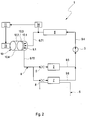
- FIGS. 1 and 2 each show a refrigerant circuit 1 with an identical basic structure of a vehicle air conditioning system of a vehicle (not shown).
- the refrigerant circuit 1 this FIGS. 1 and 2 comprises as components an evaporator 2 as an internal heat exchanger, a refrigerant compressor 3, a refrigerant condenser 4 as an external heat exchanger, a the evaporator 2 in the flow direction of the refrigerant upstream expansion valve 5. Further, the refrigerant circuit 1 comprises a series circuit of a heat exchanger 7 as a further evaporator and a heat exchanger. 7 associated expansion valve 8, which are arranged parallel to the series connection of the expansion valve 5 and the evaporator 2 in the refrigerant circuit 1. This heat exchanger 7 is coupled via a coolant circuit 6 to a heat source (not shown), which may be, for example, a high-voltage battery or an electric motor.
- a heat source not shown
- This heat exchanger 7 also works as an evaporator for cooling an air flow as a coolant or as a chiller for cooling water as a coolant. Alternatively, it can also be integrated directly into the component to be cooled and consequently act as a direct evaporator.
- the listed components are connected to form the refrigerant circuit 1 via a refrigerant line 9 with each other.
- the refrigerant compressor 3 is connected at its high-pressure side outlet via a line section 9.4 of the refrigerant line 9 with the refrigerant condenser 4, while the evaporator 2 and the heat exchanger 7 is connected via a line section 9.5 or 9.6 of the refrigerant line 9 with the low-pressure side input of the refrigerant compressor 3.
- the outlet of the refrigerant condenser 4 is connected via a line section 9.7 of the refrigerant line 9 to the expansion valve 5 associated with the evaporator 2 or to the expansion valve 8 associated with the heat exchanger 7.
- a refrigerant tank 10 is provided, which is designed in an advantageous variant as a cylinder-piston assembly.
- a displaceably mounted piston 10.3 in this cylinder-piston arrangement 10 divides the internal volume of the cylinder 10.4 of this cylinder-piston arrangement 10 into a chamber 10.1 and a further chamber 10.2, wherein the volume of the chamber 10.1 can be controlled as a function of the position of the piston 10.3 is.
- This chamber 10.1 with controllable volume is connected via a branch line 9.2 with the line section 9.7 of the refrigerant line 9 and thus represents a controllable additional volume for the refrigerant circuit 1.
- By adjusting the piston 10.3 of the refrigerant tank 10 can either the volume of the chamber 10.1 increases and thus refrigerant be sucked from the refrigerant circuit 1 and stored in this chamber 10.1 or the volume of the chamber 10.1 reduced and thus refrigerant back into the refrigerant circuit 1 are promoted back.
- the position of the piston 10.3 of the refrigerant tank 10 is adjusted by means of a control device (actuator) 15 of the refrigerant tank 10 in response to a control signal which is generated by a control unit 11 formed as a control unit as a function of operating parameters.
- control signal which is generated by a control unit 11 formed as a control unit as a function of operating parameters.
- These operating parameters are ideally detected as pressure and temperature at the outlet of the refrigerant condenser 4 by sensor means 14, for example by a pT sensor, and fed to the control unit 11 for evaluation.
- the control device 15 controls the movable piston 10.3.
- the displacement of the piston 10.3 takes place as a function of the measured subcooling of the refrigerant at the outlet of the refrigerant condenser 4. If the subcooling is too high, for example greater than 15 K, the refrigerant circuit 1 is for the currently selected interconnection (variant a: only internal heat exchanger 2 active, variant b: only heat exchanger 7 connected, or variant c: dual mode with internal heat exchanger 2 and heat exchanger 7, which is usually designed for variant c to the optimum capacity.) Crowded, so that by appropriate adjustment of the piston 10.3 a larger volume the chamber 10.1 must be provided, in which the refrigerant is stored.
- the control device 15 actuates the piston 10.3 and allows it to be moved until an acceptable supercooling occurs.
- the volume of the chamber 10.1 can be varied and thus the optimal operating point with the optimal filling with refrigerant of the refrigerant circuit 1 can be set.
- the piston 10.3 of the cylinder-piston assembly 10 should be close to the cylinder 10.4.
- This will be according to FIG. 1 realized by means of a suction 9.3, which connects the other chamber 10.2 via a suction valve 12 with the low pressure side of the refrigerant circuit 1, ideally so with the low-pressure side input of the refrigerant compressor 3 and the compressor 3 supplied refrigerant line.
- the connection of the suction 9.3 to the other chamber 10.2 is at the lowest point of the same (oil issue). Extraction of the chamber 10.2 causes a parallel force-optimized opening of the piston 10.3, since the back pressure would be reduced in the chamber 10.2.
- FIG. 2 shows a refrigerant circuit 1 of a vehicle air conditioning system compared to FIG. 1 with the same components, in particular as well is realized with a cylinder-piston arrangement as a refrigerant tank 10.
- the cylinder-piston assembly 10 is not connected via a branch line to the line section 9.7 of the refrigerant circuit 1, but that the chamber 10.1 forms with its controllable volume a line section 9.1 of the line section 9.7, so that a line section 9.71 a connection of the output of the refrigerant condenser 4 with the chamber 10.1 in the flow direction of the refrigerant produces and another line section 9.72 connects the chamber 10.1 in the flow direction of the refrigerant with the expansion valves 5 and 8, wherein the exit from the chamber 10.1 optimally at the lowest point of the chamber 10.1 to minimize possible oil deposits, but also to recycle high density, liquid refrigerant to speed up the recovery process.
- the chamber 10.1 is constantly actively flowed through by refrigerant.
- the refrigerant tank 10 In the refrigeration circuits 1 according to the FIGS. 1 and 2 it is useful to position the refrigerant tank 10 at a "cool" point in the engine compartment of the vehicle to prevent re-evaporation of the stored refrigerant.
- Optimal is the integration of the refrigerant tank 10 at a position of the refrigerant circuit 1, which comes to rest due to the applied ambient temperature of the pressure level below the level of that point at which refrigerant is supplied to the refrigerant tank 10, since a pressure gradient, the relocation from the refrigerant circuit 1 in supports the refrigerant tank 10.
- the described invention is independent of the choice of the refrigerant used. Both chemical fuels, such as R134a and R1234yf, but also natural refrigerants, e.g. R744, can be used in the air conditioners described above.
- Systems which are operated with R744 as a refrigerant are preferably designed as systems with low-pressure side main refrigerant storage, whereby also R134a Brownrepanzen similar by increasing its inner volume or by downstream built additional volumes or lifting the line dimensions (increase) are compensated.
Landscapes
- Engineering & Computer Science (AREA)
- Mechanical Engineering (AREA)
- Physics & Mathematics (AREA)
- Thermal Sciences (AREA)
- General Engineering & Computer Science (AREA)
- Life Sciences & Earth Sciences (AREA)
- Sustainable Development (AREA)
- Sustainable Energy (AREA)
- Power Engineering (AREA)
- Transportation (AREA)
- Air-Conditioning For Vehicles (AREA)
Description
- Die Erfindung betrifft eine Fahrzeugklimaanlage mit einem Kältemittelkreislauf gemäß dem Oberbegriff des Patentanspruchs 1.
- Der Einsatz von Kältemittelkreisläufen in Fahrzeugklimaanlagen ist bekannt, wobei manche Varianten eine 2-Verdampferanlage vorsehen, nämlich einen Frontverdampfer und einen Heckanlagenverdampfer. Je nach Verschaltung und aktivem Betrieb der jeweiligen Wärmeübertragung variiert der Bedarf an benötigtem aktivem Kältemittel im Kältemittelkreislauf.
- Elektrifizierte Fahrzeuge benötigen neben dem Frontverdampfer als mindestens einen Innenraumverdampfer einen separaten Kühlmittelkreislauf zur Konditionierung und Temperierung des in der Regel als Hochvoltbatterie realisierten Energiespeichers. Ein solcher Kühlmittelkreislauf wird mittels eines Wärmeübertragers mit dem Kältemittelkreislauf gekoppelt, wobei ein solcher Wärmeübertrager seinerseits ebenfalls als Verdampfer zum Kühlen eines Luftstromes bzw. als sogenannter Chiller zum Kühlen von Wasser ausgebildet ist.
- Es sind darüber hinaus Ausführungen bekannt, die den Hochvoltspeicher per Luftstrom konditionieren. Dessen Abkühlung erfolgt per luftseitig geschalteten Verdampfer, analog dem Innenraum-Wärmeübertrager. Eine weitere bekannte Ausführung ist eine Hochvoltspeicher-Direktkonditionierung mit Kältemittel, das ohne Zwischenkälteträger direkt in die Batterie geführt wird und deren Abwärme aufnimmt.
- Auch der Einsatz des Kältemittelkreislaufs der Fahrzeugklimaanlage in einem Wärmepumpenbetrieb zum Aufheizen der Fahrgastzelle ist bekannt. In seiner Funktion als Wärmepumpe ist der Kältemittelkreislauf in der Lage, einen Luft- oder auch Wasserstrom bzw. Kühlmittelstrom zu erwärmen und diese Wärme direkt bzw. indirekt an die Luft der Fahrgastzelle abzugeben. Je nach Betriebsweise der Fahrzeugklimaanlage, ob also geheizt bzw. gekühlt wird oder welche Anzahl von Wärmeübertrager aktiv betrieben werden, variiert auch in diesem Fall die zur optimalen Betriebsweise benötigte Menge an aktivem bzw. tatsächlich benötigtem Kältemittel im Kältemittelkreislauf.
- Die unterschiedlichen Betriebsweisen einer solchen Kälteanlage können somit je nach Verschaltung der Komponenten unterschiedliche Kältemittelfüllmengen als Optimum benötigen.
- Bei einer gattungsbildenden Fahrzeugklimaanlage gemäß der
DE 10 2011 118 162 A1 wird dieses Problem dadurch gelöst, dass Kältemittel aus den nichtaktiven Bereichen abgesaugt und in aktive Bereiche des Kältemittelkreislaufs durch die Schaltung einer Verbindung der nichtaktiven Bereiche mit der aktiven Niederdruckseite eingespeist wird. Insbesondere wird in bestimmten Betriebsmodi bei einem Kältemittelüberschuss Kältemittel aus den aktiven Bereichen des Kältemittelkreislaufs in die nichtaktiven Bereiche verlagert. Damit soll durch Absaugen und Auslagern von Kältemittel aus bzw. in inaktive Bereiche bzw. in aktive Bereiche des Kältemittelkreislaufs oder Komponenten desselben eine Regelungsmöglichkeit der aktiven Kältemittelfüllmenge realisiert werden. - Die
WO 2013/017936 A1 beschreibt einen Kältemittelkreislauf mit einem Kältemittelverdichter, einem ersten und zweiten Kältemittelkondensator und einem Verdampfer, dem ein Expansionsorgan vorgeschaltet ist. Dem Kältemittelkondensator ist ein Gas-Flüssigkeits-Abscheider in Strömungsrichtung des Kältemittels nachgeschaltet, so dass flüssiges Kältemittel über einen Wärmeübertrager zur indirekten Kühlung von elektrischen Komponenten des Fahrzeugs und wieder zurück in den Kältemittelkreislauf zum Expansionsorgan des Verdampfers strömen kann. Mit der Verbindungsleitung zwischen dem Gas-Flüssigkeits-Abscheider und dem Eingang dieses Wärmeübertragers kann mittels eines Ventils ein Kältemittelsammler verbunden werden. Dieser Kältemittelsammler ist als Zylinder-Kolben-Anordnung mit einem mittels eines elektrischen Antriebs verschiebbaren Kolben ausgeführt, der den Zylinder in zwei Kammern teilt. Eine dieser beiden Kammern kann mittels des Ventils mit der Verbindungsleitung so verbunden werden, dass entweder von dem Gas-Flüssigkeits-Abscheider strömendes Kühlmittel in eine Kammer eingelagert wird oder das eingelagerte Kühlmittel direkt in den Wärmeübertrager strömen kann. - Somit wird bei diesem Kältemittelkreislauf gemäß der
WO 2013/017936 A1 einerseits das gasförmige Kältemittel des Gas-Flüssigkeits-Abscheiders dem Expansionsorgan des Verdampfers und andererseits auch das in dem Wärmeübertrager verdampfte Kältemittel, welches dem Gas-Flüssigkeits-Abscheider als flüssiges Kältemittel entnommen ist, ebenso dem Expansionsorgan des Verdampfers vor einer Kühlung mittels des zweiten Kältemittelkondensators zugeführt. In Abhängigkeit der mittels Temperatursensoren am Eingang und Ausgang des Wärmeübertragers angeordneten Sensoren werden die Einlagerung von flüssigem Kältemittel in den Kältemittelsammler als auch dessen Auslagerung in den Wärmeübertrager gesteuert. Mit einer entsprechenden Einstellung des dem Kältemittelsammler zugeordneten Ventils soll verhindert werden, dass das ganze Volumen des flüssigen Kältemittels in den Kältemittelsammler strömen kann und somit ein kontinuierlicher Kältemittelstrom zum Kühlen der elektrischen Komponenten zur Verfügung steht, insbesondere wenn der Kältemittelverdichter nicht in Betrieb ist. - Um einen überhöhten Kältemitteldruck in einem Kältemittelkreislauf eine Fahrzeugklimaanlage zu verhindern, schlägt die
EP 0 274 727 vor, dem Kältemittelkreislauf Kältemittel zu entziehen und kurzfristig in einem auf der Hochdruckseite eines Kältemittelverdichters des Kältemittelkreislaufes angeordneten Kältemittelbehälter zu speichern. Hierzu ist ein von einem Drucksensor gesteuertes Magnetventil vorgesehen, über welches bei einem unzulässig hohen Druck Kältemittel in den Kältemittelbehälter strömen lässt. Dieser Kältemittelbehälter ist als Zylinder-Kolbeneinheit ausgebildet, innerhalb derer eine als Druckspeicher auf deren Kolben wirkende Feder vorgesehen ist. Anstelle des Drucksensors kann auch ein Überdruckventil eingesetzt werden, welches bei Überschreiten eines unzulässig hohen Systemdruckes öffnet und den Weg zum Kältemittelbehälter freigibt, bis der Systemdruck wieder gefallen ist. Die Rückführung des Kältemittels in den Kältemittelkreislauf erfolgt dabei kontinuierlich nach kurzzeitiger Speicherung in dem Kältemittelbehälter über ein Kapillarrohr an die Saugseite des Kältemittelverdichters. - Ferner beschreibt auch die
DE 37 21 388 C1 eine Fahrzeugklimaanlage mit einem Kältemittelkreislauf, der als Komponenten einen Verdampfer, einen Kältemittelverdichter, einen Kältemittelkondensator, einen Sammelbehälter und ein dem Verdampfer zugeordnetes Expansionsventil aufweist. Um bei einer hohen Umgebungstemperatur den Druck auf der Hochdruckseite des Kältemittelverdichters zu begrenzen, ist ein Zwischenspeicher vorgesehen, der mit der Hochdruckseite des Kältemittelverdichters über ein Überdrucksicherheitsventil verbunden ist. Bei Übersteigen eines vorgegebenen Maximaldrucks stellt dieses Überdrucksicherheitsventil eine Verbindung zum Zwischenspeicher her, so dass Kältemittel in diesen Zwischenspeicher abströmen kann. Um diesen Zwischenspeicher wieder entleeren zu können, ist ein Entladeventil vorgesehen, das den Zwischenspeicher mit der Niederdruckseite des Kältemittelverdichters verbindet. - Der Vollständigkeit halber sei auch auf die
DE 10 2009 035 329 A1 verwiesen, die eine Fahrzeugklimaanlage offenbart, welche als Komponenten einen Verdampfer, einen Kältemittelverdichter, einen Kältemittelkondensator, ein dem Verdampfer zugeordnetes Expansionsventil und einen zur Kopplung mit einem Kühlmittelkreislauf einer Batterie vorgesehener Wärmeübertrager mit zugeordnetem Expansionsventil aufweist. - Die Aufgabe der Erfindung besteht darin, eine alternative Lösung zum Stand der Technik anzugeben, mit der für jeden Betriebsmodus der Fahrzeugklimaanlage die notwendige bzw. optimale Kältemittelmenge zur Verfügung gestellt werden kann.
- Diese Aufgabe wird gelöst durch eine Fahrzeugklimaanlage mit den Merkmalen des Patentanspruchs 1.
- Eine solche Fahrzeugklimaanlage mit einem Kältemittelkreislauf, welcher als Komponenten wenigstens einen Verdampfer, einen Kältemittelverdichter, einen Kältemittelkondensator, ein dem Verdampfer zugeordnetes Expansionsventil und wenigstens einen zur Kopplung mit einem Kühlmittelkreislauf einer Wärmequelle vorgesehener Wärmeübertrager mit zugeordnetem Expansionsventil aufweist, wobei die Komponenten mittels einer Kältemittelleitung verbunden sind und die Reihenschaltung aus dem Wärmeübertrager und dem zugeordneten Expansionsventil parallel zur Reihenschaltung aus dem Verdampfer und dem zugeordneten Expansionsventil angeordnet ist, zeichnet sich erfindungsgemäß dadurch aus, dass
- ein auf der Hochdruckseite des Kältemittelverdichters mit der Kältemittelleitung verbundener Kältemittelbehälter vorgesehen ist, welcher eine Kältemittel aufnehmende Kammer mit einem steuerbaren Volumen aufweist,
- die Kammer des Kältemittelbehälters mit einem mit dem Ausgang des Kältemittelkondensators verbundenen Leitungsabschnitt der Kältemittelleitung verbunden ist,
- Sensormittel vorgesehen sind, welche zur Bestimmung des Drucks und der Temperatur des Kältemittels als Betriebsparameter am Ausgang des Kältemittelkondensators in Fließrichtung des Kältemittels angeordnet sind, und
- eine Steuereinheit vorgesehen ist, mit welcher in Abhängigkeit der Betriebsparameter des Kältemittelkreislaufs das Volumen der Kammer des Kältemittelbehälters gesteuert wird.
- Bei dieser erfindungsgemäßen Fahrzeugklimaanlage wird ein steuerbares Zusatzvolumen in den Kältemittelkreislauf in einem hochdruckseitigen Leitungsabschnitt der Kältemittelleitung realisiert, wobei dieser Leitungsabschnitt in allen Betriebsweisen genutzt wird. Dieses steuerbare Zusatzvolumen wird mittels einer ein steuerbares Volumen aufweisenden Kammer eines Kältemittelbehälters realisiert. Je nach Bedarf kann das Volumen variiert werden und der optimale Betriebspunkt der Fahrzeugklimaanlage und damit die optimale Befüllung des Systems eingestellt werden.
- Nach einer vorteilhaften Ausgestaltung der Erfindung gemäß der erstgenannten Lösung ist die Kammer des Kältemittelbehälters als Leitungsabschnitt des Leitungsabschnittes ausgebildet. Damit wird diese Kammer mit dem steuerbaren Volumen permanent von dem Kältemittel durchströmt.
- Nach einer anderen vorteilhaften Ausgestaltung der Erfindung ist die Kammer des Kältemittelbehälters über eine Abzweigleitung mit dem Leitungsabschnitt verbunden. Damit kann dem Kältemittelkreislauf Kältemittel entzogen und in die Kammer mit variablen Volumen entsprechend dem eingestellten Volumen eingelagert werden. Der Aggregatzustand des eingelagerten Kältemittels ist in diesem Systemabschnitt bevorzugt flüssig.
- Besonders vorteilhaft ist es gemäß einer weiteren Ausgestaltung der Erfindung gemäß der erstgenannten Lösung, wenn der Kältemittelbehälter als Zylinder-Kolben-Anordnung ausgebildet ist und die Kammer durch den Kolben der Zylinder-Kolben-Anordnung begrenzt ist, wobei eine undurchlässige Dichtung zwischen dem Kolben und dem Zylinder dieser Zylinder-Kolben-Anordnung anzustreben ist. Ansonsten ist vorzugsweise vorgesehen, eine von dem Kolben begrenzte weitere Kammer der Zylinder-Kolben-Anordnung über eine Absaugleitung mit der zum Kältemittelverdichter führenden Niederdruckseite des Kältemittelkreislaufs zu verbinden. Damit wird das auf der Kolbenrückseite des Kolbens sich sammelnde Kältemittel wieder in den Kältemittelkreislauf zurück gefördert, wobei dies vorzugsweise mittels eines in der Absaugleitung angeordneten Absaugventils realisiert ist, welches zur Steuerung mit der Steuereinheit verbunden ist.
- Schließlich sind gemäß einer letzten vorteilhaften Ausgestaltung der Erfindung Sensormittel vorgesehen, welche zur Bestimmung des Drucks und der Temperatur des Kältemittels als Betriebsparameter am Ausgang des Kältemittelkondensators in Fließrichtung des Kältemittels angeordnet sind. Diese Messwerte des Drucks in der Temperatur werden von der Steuereinheit, in der Regel ein Steuergerät verarbeitet und entsprechend Steuersignale zur Steuerung des Volumens der Kammer des Kältemittelbehälters bzw. zur Steuerung des Abzweigventils erzeugt.
- Die Erfindung wird nachfolgend anhand von Ausführungsbeispielen unter Bezugnahme auf die beigefügten Figuren ausführlich beschrieben. Es zeigen:
- Figur 1
- ein Prinzipschaltbild eines Kältemittelkreislaufs einer Fahrzeugklimaanlage gemäß eines ersten Ausführungsbeispiels gemäß der Erfindung, und
- Figur 2
- ein Prinzipschaltbild eines Kältemittelkreislaufes einer Fahrzeugklimaanlage gemäß eines zweiten Ausführungsbeispiels gemäß der Erfindung.
- Die
Figuren 1 und2 zeigen jeweils einen Kältemittelkreislauf 1 mit identischer Grundstruktur einer Fahrzeugklimaanlage eines Fahrzeugs (nicht dargestellt). - Der Kältemittelkreislauf 1 dieser
Figuren 1 und2 umfasst als Komponenten einen Verdampfer 2 als Innenwärmeübertrager, einen Kältemittelverdichter 3, einen Kältemittelkondensator 4 als Außenwärmeübertrager, ein dem Verdampfer 2 in Strömungsrichtung des Kältemittels vorgeschaltetes Expansionsventil 5. Ferner umfasst der Kältemittelkreislauf 1 eine Reihenschaltung aus einem Wärmeübertrager 7 als weiteren Verdampfer und einem dem Wärmeübertrager 7 zugeordneten Expansionsventil 8, die parallel zur Reihenschaltung aus dem Expansionsventil 5 und dem Verdampfer 2 in dem Kältemittelkreislauf 1 angeordnet sind. Dieser Wärmeübertrager 7 ist über einen Kühlmittelkreislauf 6 mit einer Wärmequelle (nicht dargestellt) gekoppelt, die bspw. eine Hochvoltbatterie oder ein Elektromotor darstellen kann. Dieser Wärmeübertrager 7 arbeitet ebenfalls als Verdampfer zur Kühlung eines Luftstromes als Kühlmittel oder als Chiller zum Kühlen von Wasser als Kühlmittel. Alternativ kann er auch direkt in die zu kühlende Komponente integriert sein und folglich als Direktverdampfer fungieren. Die aufgeführten Komponenten sind zur Bildung des Kältemittelkreislaufes 1 über eine Kältemittelleitung 9 miteinander verbunden. - Der Kältemittelverdichter 3 ist an seinem hochdruckseitigen Ausgang über einen Leitungsabschnitt 9.4 der Kältemittelleitung 9 mit dem Kältemittelkondensator 4 verbunden, während der Verdampfer 2 bzw. der Wärmeübertrager 7 über einen Leitungsabschnitt 9.5 bzw. 9.6 der Kältemittelleitung 9 mit dem niederdruckseitigen Eingang des Kältemittelverdichters 3 verbunden ist.
- In Strömungsrichtung des Kältemittels ist der Ausgang des Kältemittelkondensators 4 über einen Leitungsabschnitt 9.7 der Kältemittelleitung 9 mit dem dem Verdampfer 2 zugeordneten Expansionsventil 5 bzw. mit dem dem Wärmeübertrager 7 zugeordneten Expansionsventil 8 verbunden.
- Im Folgenden werden die Kältemittelkreisläufe 1 gemäß den
Figuren 1 und2 im Einzelnen erläutert. - Nach
Figur 1 ist neben dem bereits standardmäßig in dem Kältemittelkondensator 4 (mit Unterkühlfunktion) integrierten Kältemittelspeicher ein Kältemittelbehälter 10 vorgesehen, der in einer vorteilhaften Variante als Zylinder-Kolben-Anordnung ausgeführt ist. Ein in dieser Zylinder-Kolben-Anordnung 10 verschiebbar gelagerter Kolben 10.3 teilt das Innenvolumen des Zylinders 10.4 dieser Zylinder-Kolben-Anordnung 10 in eine Kammer 10.1 und eine weitere Kammer 10.2, wobei in Abhängigkeit der Stellung des Kolbens 10.3 das Volumen der Kammer 10.1 steuerbar ist. - Diese Kammer 10.1 mit steuerbaren Volumen ist über eine Abzweigleitung 9.2 mit dem Leitungsabschnitt 9.7 der Kältemittelleitung 9 verbunden und stellt damit ein steuerbares Zusatzvolumen für den Kältemittelkreislauf 1 dar. Durch Verstellen des Kolbens 10.3 des Kältemittelbehälters 10 kann entweder das Volumen der Kammer 10.1 vergrößert und damit Kältemittel aus dem Kältemittelkreislauf 1 abgesaugt und in diese Kammer 10.1 eingelagert werden oder das Volumen der Kammer 10.1 verkleinert und damit Kältemittel wieder in den Kältemittelkreislauf 1 zurück gefördert werden.
- Die Stellung des Kolbens 10.3 des Kältemittelbehälters 10 wird mittels einer Regelvorrichtung (Aktorik) 15 des Kältemittelbehälters 10 in Abhängigkeit eines Steuersignals eingestellt, welches von einer als Steuergerät ausgebildeten Steuereinheit 11 in Abhängigkeit von Betriebsparametern erzeugt wird. Diese Betriebsparameter werden idealerweise als Druck und Temperatur am Ausgang des Kältemittelkondensators 4 durch Sensormittel 14, bspw. durch einen pT-Sensor erfasst und dem Steuergerät 11 zur Auswertung zugeführt. In Abhängigkeit der gemessenen Sensorwerte steuert die Regelvorrichtung 15 den verfahrbaren Kolben 10.3 an.
- Das Verschieben des Kolbens 10.3 erfolgt in Abhängigkeit der gemessenen Unterkühlung des Kältemittels am Austritt des Kältemittelkondensators 4. Bei zu hoher Unterkühlung, bspw. größer als 15 K, ist der Kältemittelkreislauf 1 für die aktuell gewählte Verschaltung (Variante a: nur Innenwärmeübertrager 2 aktiv, Variante b: nur Wärmeübertrager 7 geschaltet, oder Variante c: Dualmode mit Innenwärmeübertrager 2 und Wärmeübertrager 7, wobei i.d.R. bei Variante c auf die optimale Füllmenge ausgelegt wird.) überfüllt, so dass durch entsprechende Verstellung des Kolbens 10.3 ein größeres Volumen durch die Kammer 10.1 bereitgestellt werden muss, in das das Kältemittel eingelagert wird. Umgekehrt wird bei zu geringer Unterkühlung das Volumen verringert und damit ausgelagertes Kältemittel wieder aktiv zurück in den Kältemittelkreislauf 1 geschoben. In Abhängigkeit der gemessenen Werte des pT-Sensors 14 steuert die Regelvorrichtung 15 den Kolben 10.3 an und lässt diesen so lange verfahren, bis sich eine akzeptable Unterkühlung einstellt.
- Damit kann in Abhängigkeit des Betriebszustandes des Kältemittelkreislaufs 1, also je nach Bedarf das Volumen der Kammer 10.1 variiert werden und damit der optimale Betriebspunkt mit der optimalen Befüllung mit Kältemittel des Kältemittelkreislaufes 1 eingestellt werden.
- In vorteilhafter Weise sollte der Kolben 10.3 der Zylinder-Kolben-Anordnung 10 dicht gegenüber dem Zylinder 10.4 sein. Jedoch ist es im Falle einer gewissen fehlenden Dichtigkeit zusätzlich möglich, das in der weiteren Kammer 10.2 gesammelte Kältemittel wieder in den Kältemittelkreislauf 1 zurückzufördern. Dies wird gemäß
Figur 1 mittels einer Absaugleitung 9.3 realisiert, die die weitere Kammer 10.2 über ein Absaugventil 12 mit der Niederdruckseite des Kältemittelkreislaufs 1, idealerweise also mit dem niederdruckseitigen Eingang des Kältemittelverdichters 3 bzw. der dem Verdichter 3 zugeführten Kältemittelleitung verbindet. Der Anschluss der Absaugleitung 9.3 an der weiteren Kammer 10.2 liegt dabei am tiefsten Punkt derselben (Ölthematik). Ein Absaugen der Kammer 10.2 bewirkt parallel ein kraftoptimiertes Öffnen des Kolbens 10.3, da der Gegendruck in der Kammer 10.2 reduziert werden würde. - Die
Figur 2 zeigt einen Kältemittelkreislauf 1 einer Fahrzeugklimaanlage, der im Vergleich zuFigur 1 mit den gleichen Komponenten, insbesondere ebenso mit einer Zylinder-Kolben-Anordnung als Kältemittelbehälter 10 realisiert ist. Der einzige Unterschied besteht darin, dass die Zylinder-Kolben-Anordnung 10 nicht über eine Abzweigleitung mit dem Leitungsabschnitt 9.7 des Kältemittelkreislaufs 1 verbunden ist, sondern dass die Kammer 10.1 mit ihrem steuerbaren Volumen einen Leitungsabschnitt 9.1 des Leitungsabschnittes 9.7 bildet, so dass ein Leitungsabschnitt 9.71 eine Verbindung des Ausgangs des Kältemittelkondensators 4 mit der Kammer 10.1 in Fließrichtung des Kältemittels herstellt und ein weiterer Leitungsabschnitt 9.72 die Kammer 10.1 in Fließrichtung des Kältemittels mit dem Expansionsventilen 5 und 8 verbindet, wobei der Austritt aus der Kammer 10.1 optimalerweise am tiefsten Punkt der Kammer 10.1 vorgesehen ist, um mögliche Öleinlagerungen zu minimieren, aber auch um hochdichtes, flüssiges Kältemittel zurückzuführen, um damit den Rückholprozess zu beschleunigen. Damit wird die Kammer 10.1 permanent von Kältemittel aktiv durchströmt. - Die Steuerung der Zylinder-Kolben-Anordnung 10 erfolgt bei diesem Kältemittelkreislauf 1 gemäß
Figur 2 in gleicher Weise wie im Zusammenhang mitFigur 1 dargestellt wurde. Auch die Eigenschaften dieses Kältemittelkreislaufes 1 sind die gleichen wie diejenigen des Kältemittelkreislaufes 1 nachFigur 1 . Im Fall eines undichten Kolbens 10.3 kann auch hier auf die Absauglösung mit Leitungsstrang 9.3 zur Niederdruckseite hinführend zurückgegriffen werden. - Bei den Kältekreisläufen 1 gemäß den
Figuren 1 und2 ist es sinnvoll, den Kältemittelbehälter 10 an einer "kühlen" Stelle im Motorraum des Fahrzeugs zur Vermeidung eines Nachverdampfens des eingelagerten Kältemittels zu positionieren. Optimal ist die Einbindung des Kältemittelbehälters 10 an einer Stelle des Kältemittelkreislauf 1, die aufgrund der anliegenden Umgebungstemperatur von der Drucklage unterhalb des Niveaus derjenigen Stelle zu liegen kommt, an welcher Kältemittel dem Kältemittelbehälter 10 zugeführt wird, da ein Druckgefälle die Umverlagerung aus dem Kältemittelkreislauf 1 in den Kältemittelbehälter 10 unterstützt. - Die Bereitstellung eines variablen Zusatzvolumen für den Kältemittelkreislauf 1 mittels eines Kältemittelbehälters 10 gemäß den
Figuren 1 und2 ist natürlich auch bei Kältemittelkreisläufen einsetzbar, die auch mit einer Wärmepumpenfunktion, gegebenenfalls mit einem weiteren Wärmepumpen-Kondensator ausgestattet sind. - Bei Systemen mit niederdruckseitiger Akkumulatoranordnung macht es Sinn, die Rückführung von Kältemittel vor dem Akkumulator einzuleiten, um eine Flüssigansaugung von Kältemittel über den Verdichter zu vermeiden. Bei Systemen, die einen inneren Wärmeübertrager integriert haben, kann aus demselben Grund die Kältemittelrückführung an dessen Eintrittsseite erfolgen. Grundsätzlich ist es aber für die Kältemittelverdichter in der Regel möglich kurzfristige Flüssigansaugung ohne Schadensauftritt zu überstehen.
- Die beschriebene Erfindung ist unabhängig von der Wahl des eingesetzten Kältemittels. Sowohl chemische Betriebsstoffe, wie bspw. R134a und R1234yf, aber auch natürliche Kältemittel, z.B. R744, können in den oben beschriebenen Klimaanlagen eingesetzt werden.
- Systeme, welche mit R744 als Kältemittel betrieben werden, sind bevorzugt als Anlagen mit niederdruckseitigem Hauptkältemittelspeicher ausgebildet, wobei auch analog dazu R134a-Füllmengendiskrepanzen bevorzugt durch Vergrößerung dessen Innenvolumens oder durch stromabwärts verbaute Zusatzvolumina bzw. Anheben der Leitungsdimensionen (Anhebung) kompensiert werden.
-
- 1
- Kältemittelkreislauf
- 2
- Verdampfer, Innenwärmeübertrager
- 3
- Kältemittelverdichter
- 4
- Kältemittelkondensator, Außenwärmeübertrager
- 5
- Expansionsventil
- 6
- Kühlmittelkreislauf
- 7
- Wärmeübertrager
- 8
- Expansionsventil
- 9
- Kältemittelleitung
- 9.1
- Leitungsabschnitt der Kältemittelleitung 9
- 9.2
- Abzweigleitung der Kältemittelleitung 9
- 9.3
- Absaugleitung der Kältemittelleitung 9
- 9.4
- Leitungsabschnitt der Kältemittelleitung 9
- 9.5
- Leitungsabschnitt der Kältemittelleitung 9
- 9.6
- Leitungsabschnitt der Kältemittelleitung 9
- 9.7
- Leitungsabschnitt der Kältemittelleitung 9
- 10
- Kältemittelbehälter, Zylinder-Kolben-Anordnung
- 10.1
- Kammer der Zylinder-Kolben-Anordnung 10
- 10.2
- weitere Kammer der Zylinder-Kolben-Anordnung 10
- 10.3
- Kolben der Zylinder-Kolben-Anordnung 10
- 10.4
- Zylinder der Zylinder-Kolben-Anordnung 10
- 11
- Steuereinheit
- 12
- Absaugventil
- 13
- Abzweigventil
- 14
- Sensormittel, pT-Sensor
- 15
- Regelvorrichtung des Kältemittelbehälters 10
Claims (6)
- Fahrzeugklimaanlage mit einem Kältemittelkreislauf (1), welcher als Komponenten wenigstens einen Verdampfer (2), einen Kältemittelverdichter (3), einen Kältemittelkondensator (4), ein dem Verdampfer (2) zugeordnetes Expansionsventil (5) und wenigstens einen zur Kopplung mit einem Kühlmittelkreislauf (6) einer Wärmequelle vorgesehener Wärmeübertrager (7) mit zugeordnetem Expansionsventil (8) aufweist, wobei die Komponenten mittels einer Kältemittelleitung (9) verbunden sind und die Reihenschaltung aus dem Wärmeübertrager (7) und dem zugeordneten Expansionsventil (8) parallel zur Reihenschaltung aus dem Verdampfer (2) und dem zugeordneten Expansionsventil (5) angeordnet ist,
dadurch gekennzeichnet, dass- ein auf der Hochdruckseite des Kältemittelverdichters (3) mit der Kältemittelleitung (9) verbundener Kältemittelbehälter (10) vorgesehen ist, welcher eine Kältemittel aufnehmende Kammer (10.1) mit einem steuerbaren Volumen aufweist,- die Kammer (10.1) des Kältemittelbehälters (10) mit einem mit dem Ausgang des Kältemittelkondensators (4) verbundenen Leitungsabschnitt (9.7, 9.71) der Kältemittelleitung (9) verbunden ist,- Sensormittel (14) vorgesehen sind, welche zur Bestimmung des Drucks und der Temperatur des Kältemittels als Betriebsparameter am Ausgang des Kältemittelkondensators (4) in Fließrichtung des Kältemittels angeordnet sind,und- eine Steuereinheit (11) vorgesehen ist, mit welcher in Abhängigkeit der Betriebsparameter des Kältemittelkreislaufes (1) das Volumen der Kammer (10.1) des Kältemittelbehälters (10) gesteuert wird. - Fahrzeugklimaanlage nach Anspruch 1,
dadurch gekennzeichnet, dass die Kammer (10.1) des Kältemittelbehälters (10) als Leitungsabschnitt (9.1) des Leitungsabschnittes (9.7) ausgebildet ist. - Fahrzeugklimaanlage nach Anspruch 1,
dadurch gekennzeichnet, dass die Kammer (10.1) des Kältemittelbehälters (10) über eine Abzweigleitung (9.2) mit dem Leitungsabschnitt (9.1-) verbunden ist. - Fahrzeugklimaanlage nach einem der vorhergehenden Ansprüche,
dadurch gekennzeichnet, dass der Kältemittelbehälter (10) als Zylinder-Kolben-Anordnung ausgebildet ist, wobei die Kammer (10.1) durch den Kolben (10.3) der Zylinder-Kolben-Anordnung (10) begrenzt ist. - Fahrzeugklimaanlage nach Anspruch 3 und 4,
dadurch gekennzeichnet, dass eine von dem Kolben (10.3) begrenzte weitere Kammer (10.2) der Zylinder-Kolben-Anordnung (10) über eine Absaugleitung (9.3) mit der zum Kältemittelverdichter (3) führenden Niederdruckseite des Kältemittelkreislaufs (1) verbunden ist. - Fahrzeugklimaanlage nach Anspruch 5,
dadurch gekennzeichnet, dass in der Absaugleitung (9.3) ein Absaugventil (12) angeordnet ist, welches zur Steuerung mit der Steuereinheit (11) verbunden ist.
Applications Claiming Priority (1)
| Application Number | Priority Date | Filing Date | Title |
|---|---|---|---|
| DE102014003908.0A DE102014003908B4 (de) | 2014-03-19 | 2014-03-19 | Fahrzeugklimaanlage mit einem Kältemittelkreislauf |
Publications (3)
| Publication Number | Publication Date |
|---|---|
| EP2921326A2 EP2921326A2 (de) | 2015-09-23 |
| EP2921326A3 EP2921326A3 (de) | 2015-12-16 |
| EP2921326B1 true EP2921326B1 (de) | 2017-10-18 |
Family
ID=52440530
Family Applications (1)
| Application Number | Title | Priority Date | Filing Date |
|---|---|---|---|
| EP15000278.0A Not-in-force EP2921326B1 (de) | 2014-03-19 | 2015-01-30 | Fahrzeugklimaanlage mit einem Kältemittelkreislauf |
Country Status (4)
| Country | Link |
|---|---|
| US (1) | US9738138B2 (de) |
| EP (1) | EP2921326B1 (de) |
| CN (1) | CN104930736B (de) |
| DE (1) | DE102014003908B4 (de) |
Cited By (3)
| Publication number | Priority date | Publication date | Assignee | Title |
|---|---|---|---|---|
| CN108027182A (zh) * | 2015-07-20 | 2018-05-11 | 克莱斯泰克雷克Ip私人有限公司 | 用于蒸汽压缩系统的子系统、蒸汽压缩系统和用于蒸汽压缩系统的方法 |
| EP3674619A4 (de) * | 2017-08-22 | 2021-05-19 | Gree Electric Appliances (Wuhan) Co., Ltd. | Klimaanlagensystem und steuerungsverfahren dafür |
| US20230107572A1 (en) * | 2020-02-20 | 2023-04-06 | Cryo Pur | Method and device for providing sub-cooling of refrigerants |
Families Citing this family (22)
| Publication number | Priority date | Publication date | Assignee | Title |
|---|---|---|---|---|
| DE102014019856B3 (de) | 2014-11-25 | 2021-10-14 | Konvekta Ag | Verfahren und Vorrichtung zur Überwachung einer Füllmenge eines Kältemittels |
| US10260787B2 (en) | 2016-05-18 | 2019-04-16 | Hill Phoenix, Inc. | Refrigeration system and method for automated charging and start-up control |
| DE102017206547A1 (de) * | 2017-04-19 | 2018-10-25 | Robert Bosch Gmbh | Verfahren zum Befüllen eines Rohrleitungskreislaufs einer Wärmepumpe mit einem Kältemittel, Behälter dafür und Wärmepumpe |
| KR20190005471A (ko) | 2017-07-06 | 2019-01-16 | 이동원 | 가변용량 냉매 저장수단을 구비한 히트 펌프 |
| KR20190005475A (ko) | 2017-07-06 | 2019-01-16 | 이동원 | 가변용량 냉매 저장수단을 구비한 고효율 히트 펌프 |
| DE102017214356A1 (de) * | 2017-08-17 | 2019-02-21 | Volkswagen Aktiengesellschaft | Klimatisierungsvorrichtung für ein Kraftfahrzeug und Verfahren zu deren Betrieb |
| JP2022508635A (ja) | 2018-11-15 | 2022-01-19 | ウォン イ、トン | 効率が改善されたヒートポンプ |
| KR20200070035A (ko) | 2018-12-08 | 2020-06-17 | 이동원 | 히트펌프의 제어방법 |
| KR20200085623A (ko) | 2019-01-07 | 2020-07-15 | 이동원 | 히트펌프의 제어방법 |
| KR20200086593A (ko) | 2019-01-09 | 2020-07-17 | 이동원 | 히트펌프 제어 방법 |
| DE102019201428B4 (de) * | 2019-02-05 | 2025-05-22 | Audi Ag | Verfahren zum Betreiben einer einen Kältemittelkreislauf aufweisenden Kälteanlage eines Fahrzeugs |
| KR20200123603A (ko) | 2019-04-22 | 2020-10-30 | 이동원 | 히트펌프 및 그 제어방법 |
| KR20210132962A (ko) | 2020-04-28 | 2021-11-05 | 이동원 | 가변용량 압축기를 구비한 히트펌프 |
| KR20210141002A (ko) | 2020-05-14 | 2021-11-23 | 이동원 | 가변용량 압축기를 구비한 히트펌프 및 그 제어방법 |
| KR20220045475A (ko) | 2020-10-05 | 2022-04-12 | 이동원 | 간단한 방법으로 팽창밸브를 제어하는 히트펌프 |
| DE102020127905B4 (de) * | 2020-10-23 | 2025-07-31 | Audi Aktiengesellschaft | Verfahren zur Kältemittelmaximierung in aktiven Systemabschnitten einer Kälteanlage, Kälteanlage und Kraftfahrzeug mit einer solchen Kälteanlage |
| DE102021200937A1 (de) | 2021-02-02 | 2022-08-04 | Mahle International Gmbh | Klimatisierungsanlage für ein Kraftfahrzeug |
| CN115084720A (zh) * | 2021-03-15 | 2022-09-20 | 北汽福田汽车股份有限公司 | 动力电池温度调节系统和车辆 |
| EP4164011B1 (de) * | 2021-10-05 | 2024-04-24 | Volvo Truck Corporation | Wärmeübertragungsflüssigkeitssystem für ein fahrzeug |
| CN114290869B (zh) * | 2021-12-03 | 2024-03-22 | 中联重科土方机械有限公司 | 车辆的热管理系统和挖掘机 |
| US20240353142A1 (en) * | 2023-04-19 | 2024-10-24 | Johnson Controls Tyco IP Holdings LLP | Adjustable working fluid reservoir for hvac system |
| US20260166961A1 (en) * | 2024-12-12 | 2026-06-18 | Fca Us Llc | Thermal expansion tank having an expansion member for use in a dielectric fluid cooling circuit |
Family Cites Families (13)
| Publication number | Priority date | Publication date | Assignee | Title |
|---|---|---|---|---|
| US2751143A (en) * | 1953-02-02 | 1956-06-19 | Westinghouse Electric Corp | Unloading mechanisms for refrigerant compressors |
| US3303663A (en) | 1965-10-20 | 1967-02-14 | Luxaire Inc | Refrigeration system charging apparatus |
| DE3701086A1 (de) * | 1987-01-16 | 1988-08-04 | Bayerische Motoren Werke Ag | Kaeltemittelkreislauf einer klimaanlage |
| DE3721388C1 (de) | 1987-06-29 | 1988-12-08 | Sueddeutsche Kuehler Behr | Vorrichtung zur Klimatisierung des Innenraums von Personenkraftwagen |
| US5848537A (en) | 1997-08-22 | 1998-12-15 | Carrier Corporation | Variable refrigerant, intrastage compression heat pump |
| AU2361899A (en) | 1998-04-09 | 1999-10-21 | Eaton Corporation | Controlling refrigerant in a closed loop recirculating system |
| DE102004038641A1 (de) * | 2004-08-09 | 2006-02-23 | Linde Kältetechnik GmbH & Co. KG | Kältekreislauf und Verfahren zum Betreiben eines Kältekreislaufes |
| US20100025125A1 (en) * | 2008-08-01 | 2010-02-04 | Daimler Ag | Method and Apparatus for the Operation of a Vehicle |
| DE102010054957A1 (de) | 2010-12-17 | 2012-06-21 | Audi Ag | Fahrzeug mit einer Klimaanlage |
| JP5798402B2 (ja) * | 2011-08-01 | 2015-10-21 | トヨタ自動車株式会社 | 冷却装置 |
| DE102011118162C5 (de) | 2011-11-10 | 2020-03-26 | Audi Ag | Kombinierte Kälteanlage und Wärmepumpe und Verfahren zum Betreiben der Anlage mit funktionsabhängiger Kältemittelverlagerung innerhalb des Kältemittelkreislaufes |
| CN203478665U (zh) | 2013-08-02 | 2014-03-12 | 优越科技股份有限公司 | 具有废热回收与节能机制的压缩循环系统 |
| JP5668811B2 (ja) | 2013-08-08 | 2015-02-12 | 三菱自動車工業株式会社 | 車両用エアコンシステムの制御装置 |
-
2014
- 2014-03-19 DE DE102014003908.0A patent/DE102014003908B4/de not_active Expired - Fee Related
-
2015
- 2015-01-30 EP EP15000278.0A patent/EP2921326B1/de not_active Not-in-force
- 2015-03-13 US US14/657,513 patent/US9738138B2/en not_active Expired - Fee Related
- 2015-03-17 CN CN201510116460.5A patent/CN104930736B/zh not_active Expired - Fee Related
Non-Patent Citations (1)
| Title |
|---|
| None * |
Cited By (6)
| Publication number | Priority date | Publication date | Assignee | Title |
|---|---|---|---|---|
| CN108027182A (zh) * | 2015-07-20 | 2018-05-11 | 克莱斯泰克雷克Ip私人有限公司 | 用于蒸汽压缩系统的子系统、蒸汽压缩系统和用于蒸汽压缩系统的方法 |
| CN113834247A (zh) * | 2015-07-20 | 2021-12-24 | 克莱斯泰克雷克Ip私人有限公司 | 蒸气压缩系统及用于其的子系统 |
| CN113834247B (zh) * | 2015-07-20 | 2023-09-01 | 克莱斯泰克雷克Ip私人有限公司 | 蒸气压缩系统及用于其的子系统 |
| EP3674619A4 (de) * | 2017-08-22 | 2021-05-19 | Gree Electric Appliances (Wuhan) Co., Ltd. | Klimaanlagensystem und steuerungsverfahren dafür |
| US20230107572A1 (en) * | 2020-02-20 | 2023-04-06 | Cryo Pur | Method and device for providing sub-cooling of refrigerants |
| US12181190B2 (en) * | 2020-02-20 | 2024-12-31 | Cryo Pur | Method and device for providing sub-cooling of refrigerants |
Also Published As
| Publication number | Publication date |
|---|---|
| CN104930736A (zh) | 2015-09-23 |
| DE102014003908B4 (de) | 2015-10-15 |
| US20150266358A1 (en) | 2015-09-24 |
| EP2921326A2 (de) | 2015-09-23 |
| DE102014003908A1 (de) | 2015-09-24 |
| US9738138B2 (en) | 2017-08-22 |
| CN104930736B (zh) | 2017-09-29 |
| EP2921326A3 (de) | 2015-12-16 |
Similar Documents
| Publication | Publication Date | Title |
|---|---|---|
| DE102014003908B4 (de) | Fahrzeugklimaanlage mit einem Kältemittelkreislauf | |
| DE102018209769B4 (de) | Verfahren zum Betreiben einer einen Kältemittelkreislauf aufweisenden Kälteanlage eines Fahrzeugs | |
| DE102020117471B4 (de) | Wärmepumpenanordnung mit indirekter Batterieerwärmung für batteriebetriebene Kraftfahrzeuge und Verfahren zum Betreiben einer Wärmepumpenanordnung | |
| DE112020004318T5 (de) | Anschlussmodul | |
| DE102019201427B4 (de) | Verfahren zum Betreiben eines Kältemittelkreislaufs einer Kälteanlage eines Fahrzeugs | |
| DE102015212550A1 (de) | Kältekreis, Verfahren zur Klimatisierung eines Fahrzeugs und Fahrzeug | |
| WO2006010487A1 (de) | Kühlsystem, insbesondere für ein kraftfahrzeug, und verfahren zum kühlen einer wärmequelle | |
| EP1572479A1 (de) | Klimaanlage, insbesondere für kraftfahrzeuge | |
| DE102013206626A1 (de) | Wärmepumpenanlage sowie Verfahren zur Klimatisierung eines Fahrzeuges | |
| DE102016007490A1 (de) | Verfahren zum Betreiben einer Kälteanlage eines Fahrzeugs | |
| DE102012022564A1 (de) | Klimatisierungsvorrichtung für ein Kraftfahrzeug, Kraftfahrzeug und Betriebsverfahren dafür | |
| DE102018113687A1 (de) | Vorrichtung und Verfahren zur Kühlung von Batteriezellenmodulen | |
| DE102015107719A1 (de) | Kältemittel-Akkumulator für einen Kältemittelkreislauf und Kältemittelkreislauf mit einem solchen Kältemittel-Akkumulator | |
| WO2019214927A1 (de) | Kälteanlage für ein fahrzeug mit einem eine wärmepumpenfunktion aufweisenden kältemittelkreislauf | |
| DE102015006189A1 (de) | Verfahren zur zulässigen Füllstands- und Füllmengenerhöhung einer Fahrzeugkälteanlage sowie Fahrzeugkälteanlage zur Durchführung des Verfahrens | |
| DE102012014242A1 (de) | Fahrzeugklimaanlage | |
| EP1625957B1 (de) | Fahrzeug-Kühlsystem | |
| DE102020106626B4 (de) | Kältemittelkreislauf für ein Kraftfahrzeug und Verfahren zum Betreiben eines solchen Kältemittelkreislaufs | |
| EP1744108B1 (de) | Anordnung in einem Kältekreislauf | |
| DE10233415B4 (de) | System zum Heizen und Kühlen eines Innenraums eines Fahrzeugs | |
| DE102014003907B4 (de) | Fahrzeugklimaanlage mit einem Kältemittelkreislauf mit Wärmepumpenfunktionalität | |
| DE102019127796A1 (de) | Aufdach-Klimatisierungseinheit | |
| WO2020078609A1 (de) | Kältekreislauf mit druckausgleich zwischen mehreren kondensatoren | |
| DE102014117627A1 (de) | Fahrzeug-Klimasystem und Verfahren zum Betrieb eines Fahrzeugklimasystems | |
| DE10318655C5 (de) | Klimatisierungssystem für ein Kraftfahrzeug und Verfahren zum Betreiben desselben |
Legal Events
| Date | Code | Title | Description |
|---|---|---|---|
| PUAI | Public reference made under article 153(3) epc to a published international application that has entered the european phase |
Free format text: ORIGINAL CODE: 0009012 |
|
| AK | Designated contracting states |
Kind code of ref document: A2 Designated state(s): AL AT BE BG CH CY CZ DE DK EE ES FI FR GB GR HR HU IE IS IT LI LT LU LV MC MK MT NL NO PL PT RO RS SE SI SK SM TR |
|
| AX | Request for extension of the european patent |
Extension state: BA ME |
|
| PUAL | Search report despatched |
Free format text: ORIGINAL CODE: 0009013 |
|
| AK | Designated contracting states |
Kind code of ref document: A3 Designated state(s): AL AT BE BG CH CY CZ DE DK EE ES FI FR GB GR HR HU IE IS IT LI LT LU LV MC MK MT NL NO PL PT RO RS SE SI SK SM TR |
|
| AX | Request for extension of the european patent |
Extension state: BA ME |
|
| RIC1 | Information provided on ipc code assigned before grant |
Ipc: F25B 41/00 20060101ALI20151112BHEP Ipc: B60H 1/32 20060101ALI20151112BHEP Ipc: F25B 45/00 20060101ALI20151112BHEP Ipc: B60H 1/00 20060101AFI20151112BHEP Ipc: B60L 11/18 20060101ALI20151112BHEP |
|
| 17P | Request for examination filed |
Effective date: 20160616 |
|
| RBV | Designated contracting states (corrected) |
Designated state(s): AL AT BE BG CH CY CZ DE DK EE ES FI FR GB GR HR HU IE IS IT LI LT LU LV MC MK MT NL NO PL PT RO RS SE SI SK SM TR |
|
| REG | Reference to a national code |
Ref country code: DE Ref legal event code: R079 Ref document number: 502015002100 Country of ref document: DE Free format text: PREVIOUS MAIN CLASS: B60H0001000000 Ipc: F25B0005020000 |
|
| GRAP | Despatch of communication of intention to grant a patent |
Free format text: ORIGINAL CODE: EPIDOSNIGR1 |
|
| RIC1 | Information provided on ipc code assigned before grant |
Ipc: F25B 5/02 20060101AFI20170622BHEP Ipc: B60L 11/18 20060101ALI20170622BHEP Ipc: F25B 41/00 20060101ALI20170622BHEP Ipc: B60H 1/32 20060101ALI20170622BHEP Ipc: F25B 49/02 20060101ALI20170622BHEP Ipc: F25B 45/00 20060101ALI20170622BHEP Ipc: B60H 1/00 20060101ALI20170622BHEP |
|
| INTG | Intention to grant announced |
Effective date: 20170713 |
|
| GRAS | Grant fee paid |
Free format text: ORIGINAL CODE: EPIDOSNIGR3 |
|
| GRAA | (expected) grant |
Free format text: ORIGINAL CODE: 0009210 |
|
| AK | Designated contracting states |
Kind code of ref document: B1 Designated state(s): AL AT BE BG CH CY CZ DE DK EE ES FI FR GB GR HR HU IE IS IT LI LT LU LV MC MK MT NL NO PL PT RO RS SE SI SK SM TR |
|
| REG | Reference to a national code |
Ref country code: GB Ref legal event code: FG4D Free format text: NOT ENGLISH |
|
| REG | Reference to a national code |
Ref country code: CH Ref legal event code: EP |
|
| REG | Reference to a national code |
Ref country code: AT Ref legal event code: REF Ref document number: 938320 Country of ref document: AT Kind code of ref document: T Effective date: 20171115 Ref country code: IE Ref legal event code: FG4D Free format text: LANGUAGE OF EP DOCUMENT: GERMAN |
|
| REG | Reference to a national code |
Ref country code: DE Ref legal event code: R096 Ref document number: 502015002100 Country of ref document: DE |
|
| REG | Reference to a national code |
Ref country code: FR Ref legal event code: PLFP Year of fee payment: 4 |
|
| REG | Reference to a national code |
Ref country code: NL Ref legal event code: MP Effective date: 20171018 |
|
| REG | Reference to a national code |
Ref country code: LT Ref legal event code: MG4D |
|
| PG25 | Lapsed in a contracting state [announced via postgrant information from national office to epo] |
Ref country code: NL Free format text: LAPSE BECAUSE OF FAILURE TO SUBMIT A TRANSLATION OF THE DESCRIPTION OR TO PAY THE FEE WITHIN THE PRESCRIBED TIME-LIMIT Effective date: 20171018 |
|
| PG25 | Lapsed in a contracting state [announced via postgrant information from national office to epo] |
Ref country code: NO Free format text: LAPSE BECAUSE OF FAILURE TO SUBMIT A TRANSLATION OF THE DESCRIPTION OR TO PAY THE FEE WITHIN THE PRESCRIBED TIME-LIMIT Effective date: 20180118 Ref country code: SE Free format text: LAPSE BECAUSE OF FAILURE TO SUBMIT A TRANSLATION OF THE DESCRIPTION OR TO PAY THE FEE WITHIN THE PRESCRIBED TIME-LIMIT Effective date: 20171018 Ref country code: LT Free format text: LAPSE BECAUSE OF FAILURE TO SUBMIT A TRANSLATION OF THE DESCRIPTION OR TO PAY THE FEE WITHIN THE PRESCRIBED TIME-LIMIT Effective date: 20171018 Ref country code: FI Free format text: LAPSE BECAUSE OF FAILURE TO SUBMIT A TRANSLATION OF THE DESCRIPTION OR TO PAY THE FEE WITHIN THE PRESCRIBED TIME-LIMIT Effective date: 20171018 Ref country code: ES Free format text: LAPSE BECAUSE OF FAILURE TO SUBMIT A TRANSLATION OF THE DESCRIPTION OR TO PAY THE FEE WITHIN THE PRESCRIBED TIME-LIMIT Effective date: 20171018 |
|
| PG25 | Lapsed in a contracting state [announced via postgrant information from national office to epo] |
Ref country code: GR Free format text: LAPSE BECAUSE OF FAILURE TO SUBMIT A TRANSLATION OF THE DESCRIPTION OR TO PAY THE FEE WITHIN THE PRESCRIBED TIME-LIMIT Effective date: 20180119 Ref country code: HR Free format text: LAPSE BECAUSE OF FAILURE TO SUBMIT A TRANSLATION OF THE DESCRIPTION OR TO PAY THE FEE WITHIN THE PRESCRIBED TIME-LIMIT Effective date: 20171018 Ref country code: RS Free format text: LAPSE BECAUSE OF FAILURE TO SUBMIT A TRANSLATION OF THE DESCRIPTION OR TO PAY THE FEE WITHIN THE PRESCRIBED TIME-LIMIT Effective date: 20171018 Ref country code: LV Free format text: LAPSE BECAUSE OF FAILURE TO SUBMIT A TRANSLATION OF THE DESCRIPTION OR TO PAY THE FEE WITHIN THE PRESCRIBED TIME-LIMIT Effective date: 20171018 Ref country code: BG Free format text: LAPSE BECAUSE OF FAILURE TO SUBMIT A TRANSLATION OF THE DESCRIPTION OR TO PAY THE FEE WITHIN THE PRESCRIBED TIME-LIMIT Effective date: 20180118 Ref country code: IS Free format text: LAPSE BECAUSE OF FAILURE TO SUBMIT A TRANSLATION OF THE DESCRIPTION OR TO PAY THE FEE WITHIN THE PRESCRIBED TIME-LIMIT Effective date: 20180218 |
|
| REG | Reference to a national code |
Ref country code: DE Ref legal event code: R097 Ref document number: 502015002100 Country of ref document: DE |
|
| PG25 | Lapsed in a contracting state [announced via postgrant information from national office to epo] |
Ref country code: EE Free format text: LAPSE BECAUSE OF FAILURE TO SUBMIT A TRANSLATION OF THE DESCRIPTION OR TO PAY THE FEE WITHIN THE PRESCRIBED TIME-LIMIT Effective date: 20171018 Ref country code: DK Free format text: LAPSE BECAUSE OF FAILURE TO SUBMIT A TRANSLATION OF THE DESCRIPTION OR TO PAY THE FEE WITHIN THE PRESCRIBED TIME-LIMIT Effective date: 20171018 Ref country code: SK Free format text: LAPSE BECAUSE OF FAILURE TO SUBMIT A TRANSLATION OF THE DESCRIPTION OR TO PAY THE FEE WITHIN THE PRESCRIBED TIME-LIMIT Effective date: 20171018 Ref country code: CZ Free format text: LAPSE BECAUSE OF FAILURE TO SUBMIT A TRANSLATION OF THE DESCRIPTION OR TO PAY THE FEE WITHIN THE PRESCRIBED TIME-LIMIT Effective date: 20171018 |
|
| PLBE | No opposition filed within time limit |
Free format text: ORIGINAL CODE: 0009261 |
|
| STAA | Information on the status of an ep patent application or granted ep patent |
Free format text: STATUS: NO OPPOSITION FILED WITHIN TIME LIMIT |
|
| PG25 | Lapsed in a contracting state [announced via postgrant information from national office to epo] |
Ref country code: RO Free format text: LAPSE BECAUSE OF FAILURE TO SUBMIT A TRANSLATION OF THE DESCRIPTION OR TO PAY THE FEE WITHIN THE PRESCRIBED TIME-LIMIT Effective date: 20171018 Ref country code: SM Free format text: LAPSE BECAUSE OF FAILURE TO SUBMIT A TRANSLATION OF THE DESCRIPTION OR TO PAY THE FEE WITHIN THE PRESCRIBED TIME-LIMIT Effective date: 20171018 Ref country code: PL Free format text: LAPSE BECAUSE OF FAILURE TO SUBMIT A TRANSLATION OF THE DESCRIPTION OR TO PAY THE FEE WITHIN THE PRESCRIBED TIME-LIMIT Effective date: 20171018 Ref country code: IT Free format text: LAPSE BECAUSE OF FAILURE TO SUBMIT A TRANSLATION OF THE DESCRIPTION OR TO PAY THE FEE WITHIN THE PRESCRIBED TIME-LIMIT Effective date: 20171018 |
|
| REG | Reference to a national code |
Ref country code: CH Ref legal event code: PL |
|
| 26N | No opposition filed |
Effective date: 20180719 |
|
| PG25 | Lapsed in a contracting state [announced via postgrant information from national office to epo] |
Ref country code: MT Free format text: LAPSE BECAUSE OF FAILURE TO SUBMIT A TRANSLATION OF THE DESCRIPTION OR TO PAY THE FEE WITHIN THE PRESCRIBED TIME-LIMIT Effective date: 20171018 |
|
| PG25 | Lapsed in a contracting state [announced via postgrant information from national office to epo] |
Ref country code: LU Free format text: LAPSE BECAUSE OF NON-PAYMENT OF DUE FEES Effective date: 20180130 |
|
| REG | Reference to a national code |
Ref country code: IE Ref legal event code: MM4A |
|
| REG | Reference to a national code |
Ref country code: BE Ref legal event code: MM Effective date: 20180131 |
|
| PG25 | Lapsed in a contracting state [announced via postgrant information from national office to epo] |
Ref country code: BE Free format text: LAPSE BECAUSE OF NON-PAYMENT OF DUE FEES Effective date: 20180131 Ref country code: CH Free format text: LAPSE BECAUSE OF NON-PAYMENT OF DUE FEES Effective date: 20180131 Ref country code: LI Free format text: LAPSE BECAUSE OF NON-PAYMENT OF DUE FEES Effective date: 20180131 Ref country code: SI Free format text: LAPSE BECAUSE OF FAILURE TO SUBMIT A TRANSLATION OF THE DESCRIPTION OR TO PAY THE FEE WITHIN THE PRESCRIBED TIME-LIMIT Effective date: 20171018 |
|
| PG25 | Lapsed in a contracting state [announced via postgrant information from national office to epo] |
Ref country code: IE Free format text: LAPSE BECAUSE OF NON-PAYMENT OF DUE FEES Effective date: 20180130 |
|
| PG25 | Lapsed in a contracting state [announced via postgrant information from national office to epo] |
Ref country code: MC Free format text: LAPSE BECAUSE OF FAILURE TO SUBMIT A TRANSLATION OF THE DESCRIPTION OR TO PAY THE FEE WITHIN THE PRESCRIBED TIME-LIMIT Effective date: 20171018 |
|
| PG25 | Lapsed in a contracting state [announced via postgrant information from national office to epo] |
Ref country code: TR Free format text: LAPSE BECAUSE OF FAILURE TO SUBMIT A TRANSLATION OF THE DESCRIPTION OR TO PAY THE FEE WITHIN THE PRESCRIBED TIME-LIMIT Effective date: 20171018 |
|
| PGFP | Annual fee paid to national office [announced via postgrant information from national office to epo] |
Ref country code: GB Payment date: 20200128 Year of fee payment: 6 Ref country code: DE Payment date: 20200131 Year of fee payment: 6 |
|
| PG25 | Lapsed in a contracting state [announced via postgrant information from national office to epo] |
Ref country code: PT Free format text: LAPSE BECAUSE OF FAILURE TO SUBMIT A TRANSLATION OF THE DESCRIPTION OR TO PAY THE FEE WITHIN THE PRESCRIBED TIME-LIMIT Effective date: 20171018 |
|
| PG25 | Lapsed in a contracting state [announced via postgrant information from national office to epo] |
Ref country code: HU Free format text: LAPSE BECAUSE OF FAILURE TO SUBMIT A TRANSLATION OF THE DESCRIPTION OR TO PAY THE FEE WITHIN THE PRESCRIBED TIME-LIMIT; INVALID AB INITIO Effective date: 20150130 Ref country code: CY Free format text: LAPSE BECAUSE OF FAILURE TO SUBMIT A TRANSLATION OF THE DESCRIPTION OR TO PAY THE FEE WITHIN THE PRESCRIBED TIME-LIMIT Effective date: 20171018 Ref country code: MK Free format text: LAPSE BECAUSE OF NON-PAYMENT OF DUE FEES Effective date: 20171018 |
|
| PGFP | Annual fee paid to national office [announced via postgrant information from national office to epo] |
Ref country code: FR Payment date: 20200128 Year of fee payment: 6 |
|
| PG25 | Lapsed in a contracting state [announced via postgrant information from national office to epo] |
Ref country code: AL Free format text: LAPSE BECAUSE OF FAILURE TO SUBMIT A TRANSLATION OF THE DESCRIPTION OR TO PAY THE FEE WITHIN THE PRESCRIBED TIME-LIMIT Effective date: 20171018 |
|
| REG | Reference to a national code |
Ref country code: AT Ref legal event code: MM01 Ref document number: 938320 Country of ref document: AT Kind code of ref document: T Effective date: 20200130 |
|
| PG25 | Lapsed in a contracting state [announced via postgrant information from national office to epo] |
Ref country code: AT Free format text: LAPSE BECAUSE OF NON-PAYMENT OF DUE FEES Effective date: 20200130 |
|
| REG | Reference to a national code |
Ref country code: DE Ref legal event code: R119 Ref document number: 502015002100 Country of ref document: DE |
|
| GBPC | Gb: european patent ceased through non-payment of renewal fee |
Effective date: 20210130 |
|
| PG25 | Lapsed in a contracting state [announced via postgrant information from national office to epo] |
Ref country code: FR Free format text: LAPSE BECAUSE OF NON-PAYMENT OF DUE FEES Effective date: 20210131 |
|
| PG25 | Lapsed in a contracting state [announced via postgrant information from national office to epo] |
Ref country code: GB Free format text: LAPSE BECAUSE OF NON-PAYMENT OF DUE FEES Effective date: 20210130 Ref country code: DE Free format text: LAPSE BECAUSE OF NON-PAYMENT OF DUE FEES Effective date: 20210803 |