EP2921310A1 - System for printing on three-dimensional object and program for printing on three-dimensional object - Google Patents
System for printing on three-dimensional object and program for printing on three-dimensional object Download PDFInfo
- Publication number
- EP2921310A1 EP2921310A1 EP13854574.4A EP13854574A EP2921310A1 EP 2921310 A1 EP2921310 A1 EP 2921310A1 EP 13854574 A EP13854574 A EP 13854574A EP 2921310 A1 EP2921310 A1 EP 2921310A1
- Authority
- EP
- European Patent Office
- Prior art keywords
- dimensional object
- image
- printing
- designated
- Prior art date
- Legal status (The legal status is an assumption and is not a legal conclusion. Google has not performed a legal analysis and makes no representation as to the accuracy of the status listed.)
- Withdrawn
Links
Images










Classifications
-
- B—PERFORMING OPERATIONS; TRANSPORTING
- B41—PRINTING; LINING MACHINES; TYPEWRITERS; STAMPS
- B41J—TYPEWRITERS; SELECTIVE PRINTING MECHANISMS, i.e. MECHANISMS PRINTING OTHERWISE THAN FROM A FORME; CORRECTION OF TYPOGRAPHICAL ERRORS
- B41J29/00—Details of, or accessories for, typewriters or selective printing mechanisms not otherwise provided for
- B41J29/38—Drives, motors, controls or automatic cut-off devices for the entire printing mechanism
-
- B—PERFORMING OPERATIONS; TRANSPORTING
- B41—PRINTING; LINING MACHINES; TYPEWRITERS; STAMPS
- B41J—TYPEWRITERS; SELECTIVE PRINTING MECHANISMS, i.e. MECHANISMS PRINTING OTHERWISE THAN FROM A FORME; CORRECTION OF TYPOGRAPHICAL ERRORS
- B41J3/00—Typewriters or selective printing or marking mechanisms characterised by the purpose for which they are constructed
- B41J3/407—Typewriters or selective printing or marking mechanisms characterised by the purpose for which they are constructed for marking on special material
- B41J3/4073—Printing on three-dimensional objects not being in sheet or web form, e.g. spherical or cubic objects
-
- B—PERFORMING OPERATIONS; TRANSPORTING
- B41—PRINTING; LINING MACHINES; TYPEWRITERS; STAMPS
- B41J—TYPEWRITERS; SELECTIVE PRINTING MECHANISMS, i.e. MECHANISMS PRINTING OTHERWISE THAN FROM A FORME; CORRECTION OF TYPOGRAPHICAL ERRORS
- B41J3/00—Typewriters or selective printing or marking mechanisms characterised by the purpose for which they are constructed
- B41J3/407—Typewriters or selective printing or marking mechanisms characterised by the purpose for which they are constructed for marking on special material
- B41J3/4073—Printing on three-dimensional objects not being in sheet or web form, e.g. spherical or cubic objects
- B41J3/40731—Holders for objects, e. g. holders specially adapted to the shape of the object to be printed or adapted to hold several objects
-
- G—PHYSICS
- G06—COMPUTING OR CALCULATING; COUNTING
- G06F—ELECTRIC DIGITAL DATA PROCESSING
- G06F3/00—Input arrangements for transferring data to be processed into a form capable of being handled by the computer; Output arrangements for transferring data from processing unit to output unit, e.g. interface arrangements
- G06F3/12—Digital output to print unit, e.g. line printer, chain printer
- G06F3/1201—Dedicated interfaces to print systems
- G06F3/1202—Dedicated interfaces to print systems specifically adapted to achieve a particular effect
- G06F3/1203—Improving or facilitating administration, e.g. print management
- G06F3/1205—Improving or facilitating administration, e.g. print management resulting in increased flexibility in print job configuration, e.g. job settings, print requirements, job tickets
-
- G—PHYSICS
- G06—COMPUTING OR CALCULATING; COUNTING
- G06F—ELECTRIC DIGITAL DATA PROCESSING
- G06F3/00—Input arrangements for transferring data to be processed into a form capable of being handled by the computer; Output arrangements for transferring data from processing unit to output unit, e.g. interface arrangements
- G06F3/12—Digital output to print unit, e.g. line printer, chain printer
- G06F3/1201—Dedicated interfaces to print systems
- G06F3/1223—Dedicated interfaces to print systems specifically adapted to use a particular technique
- G06F3/1237—Print job management
- G06F3/1253—Configuration of print job parameters, e.g. using UI at the client
- G06F3/1256—User feedback, e.g. print preview, test print, proofing, pre-flight checks
-
- G—PHYSICS
- G06—COMPUTING OR CALCULATING; COUNTING
- G06F—ELECTRIC DIGITAL DATA PROCESSING
- G06F3/00—Input arrangements for transferring data to be processed into a form capable of being handled by the computer; Output arrangements for transferring data from processing unit to output unit, e.g. interface arrangements
- G06F3/12—Digital output to print unit, e.g. line printer, chain printer
- G06F3/1201—Dedicated interfaces to print systems
- G06F3/1202—Dedicated interfaces to print systems specifically adapted to achieve a particular effect
- G06F3/1203—Improving or facilitating administration, e.g. print management
- G06F3/1208—Improving or facilitating administration, e.g. print management resulting in improved quality of the output result, e.g. print layout, colours, workflows, print preview
Definitions
- the present invention relates to a system for printing on a three-dimensional object which prints an image on a three-dimensional object.
- Patent Document 1 an ink jet printer that prints an image on a button used for clothing has been known as a system for printing on a three-dimensional object which prints an image on a three-dimensional object (see Patent Document 1).
- Patent Document 1 JP 4041470 B
- an angle of arrangement of the three-dimensional object relative to the ink jet printer and an image that is to be printed need to be changed by a user each time printing of an image from one direction is completed, and there is a problem regarding the trouble to be taken therefor.
- the present invention aims to provide a system for printing on a three-dimensional object that can facilitate printing of images from a plurality of directions onto the three-dimensional object compared to the conventional technique.
- a system for printing on a three-dimensional object of the present invention includes: a recording head including a nozzle surface on which a nozzle for discharging ink is formed; a three-dimensional object supporting device that supports a three-dimensional object rotatively with a predetermined axis as a center; and a print control section that causes the recording head to print an image on the three-dimensional object while rotating the three-dimensional object by the three-dimensional object supporting device, wherein the print control section causes the three-dimensional object supporting device to support the three-dimensional object at a designated angle, for each of designated angles that are angles being designated, and causes the recording head to print divided images on the three-dimensional object, the divided images being images that are divided from a print image being an image to be printed on the three-dimensional object, the divided images being set with respect to the designated angles, and the system further includes: an image accepting section that accepts the print image; and an image dividing section that divides the print image received by the image accepting section in association with the designated angles to set the divided images to the designated angles
- the system for printing on a three-dimensional object of the present invention performs printing by automatically changing the support angle of the three-dimensional object with respect to the nozzle surface, and the image to be printed on the three-dimensional object in the case where the three-dimensional object is supported by the aforesaid angle with respect to the nozzle surface, so that the printing of images from the plurality of directions on the three-dimensional object can be facilitated compared to in the conventional technique.
- the system for printing on a three-dimensional object of the present invention automatically divides the image to be printed on the three-dimensional object with respect to the plurality of designated angles, so that the printing of images from the plurality of directions on the three-dimensional object can be facilitated compared to in the conventional technique.
- the image dividing section may set the divided images in a state where boundary portions of adjacent divided images are overlapped.
- the system for printing on a three-dimensional object of the present invention prints the respective divided images on the three-dimensional object while the boundary portions of the adjacent divided images are overlapped, so that the adjacent divided images are prevented from being printed on the three-dimensional object by being apart by various errors upon printing, as a result of which a generation of awkward splits between the adjacent divided images can be prevented.
- the system for printing on a three-dimensional object of the present invention can improve quality of the printing on the three-dimensional object compared to a configuration in which the respective divided images are printed on the three-dimensional object without the boundary portions of the adjacent divided images being overlapped.
- the image dividing section may set the divided images in a state where a concentration becomes lower towards an end of each of the divided images at the boundary portions.
- the system for printing on a three-dimensional object of the present invention prints the respective divided image on the three-dimensional object in the state where the concentration becomes lower toward the end of each divided image at the boundary portions of the adjacent divided images, so that a generation of an awkward altering line of images caused by the concentration being extremely denser at the overlapped portions than at other portions within the boundary portions of the adjacent divided images can be prevented. Accordingly, the system for printing on a three-dimensional object of the present invention can improve the quality of the printing on the three-dimensional object compared to a configuration in which the respective divided images are printed on the three-dimensional object without the concentration being changed at the boundary portions of the adjacent divided images.
- the print control section may change, for each of the designated angles, orthogonal-direction positions being relative positions of the recording head and the three-dimensional object supporting device in a direction orthogonally intersecting the nozzle surface, to orthogonal-direction setting positions being the orthogonal-direction positions that are set for the designated angle, and the system for printing on a three-dimensional object may include an orthogonal-direction position setting section that sets the orthogonal-direction setting positions for the designated angle based on a size of the three-dimensional object inputted from outside, and the designated angle.
- the relative positions of the recording head and the three-dimensional object supporting device in the direction orthogonally intersecting the nozzle surface are automatically changed to suitable positions according to the size of the three-dimensional object, and the designated angle, so that it can facilitate printing of the images from the plurality of directions on the three-dimensional object compared to a configuration in which the user must input the relative positions of the recording head and the three-dimensional object supporting device in the direction orthogonally intersecting the nozzle surface for each of the designated angles.
- the print control section may change, for each of the designated angles, parallel-direction positions being relative positions of the recording head and the three-dimensional object supporting device in a direction parallel to the nozzle surface, to parallel-direction setting positions being the parallel-direction positions that are set for the designated angle
- the system for printing on a three-dimensional object may include a parallel-direction position setting section that sets the parallel-direction setting positions for the designated angle based on a size of the three-dimensional object inputted from outside, and the designated angle.
- the relative positions of the recording head and the three-dimensional object supporting device in the direction parallel to the nozzle surface are automatically changed to suitable positions according to the size of the three-dimensional object, and the designated angle, so that it can facilitate printing of the images from the plurality of directions on the three-dimensional object compared to a configuration in which the user must input the relative positions of the recording head and the three-dimensional object supporting device in the direction parallel to the nozzle surface for each of the designated angles.
- a program of the present invention for printing on a three-dimensional object is to be executed by a computer that controls an ink jet printer that is provided with: a recording head including a nozzle surface on which a nozzle for discharging ink is formed; a three-dimensional object supporting device that supports the three-dimensional object rotatively with a predetermined axis as a center; and a print control section that causes the recording head to print an image on the three-dimensional object while rotating the three-dimensional object by the three-dimensional object supporting device, wherein the print control section causes the three-dimensional object supporting device to support the three-dimensional object at a designated angle, for each of designated angles that are angles being designated, and causes the recording head to print divided images on the three-dimensional object, the divided images being images that are divided from a print image being an image to be printed on the three-dimensional object, the divided images being set with respect to the designated angles, and the program causes the computer to function as: an image accepting section that accepts the print image; and an image dividing section that divides the print image
- the computer that executes the program for printing on a three-dimensional object of the present invention automatically divides the image to be printed on the three-dimensional object for the plurality of designated angles, so it can facilitate printing of the images from the plurality of directions on the three-dimensional object compared to in the conventional technique.
- the system for printing on a three-dimensional object of the present invention can facilitate printing of the images from the plurality of directions on the three-dimensional object compared to the conventional technique.
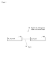
- FIG. 1 is a block diagram of a system 10 for printing on a three-dimensional object according to the present embodiment.
- the system 10 for printing on a three-dimensional object is provided with an ink jet printer 20 that prints an image on a three-dimensional object 90 (see FIG. 2 ) such as a cover for a portable phone such as a smartphone, and a computer 60 that inputs print data to the ink jet printer 20.
- the ink jet printer 20 and the computer 60 are connected communicably to each other via a cable 11 such as a USB (Universal Serial Bus) cable.
- the ink jet printer 20 and the computer 60 may be connected communicably to each other via a network such as a LAN (Local Area Network), Internet, or the like instead of the cable 11.
- LAN Local Area Network
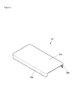
- FIG. 2 is an outer perspective view of the three-dimensional object 90 on which an image is printed by the ink jet printer 20.
- the three-dimensional object 90 includes a main surface part 90a where a main surface, being a primary surface, is formed, a first side surface part 90b where a first side surface being a surface that is substantially orthogonal to the main surface and continued from the main surface is formed, and a second side surface part 90c where a second side surface being a surface that is substantially orthogonal to the main surface and continued from the main surface on an opposite side from the first side surface is formed.
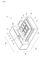
- FIG. 3 is an outer perspective view of the ink jet printer 20.
- the ink jet printer 20 includes a table 21 having an installing section 21a that is installed on a location of installation such as a floor, a main body 22 extending in a main scanning direction shown by an arrow 20a, and a three-dimensional object supporting device 30 that rotatably supports the three-dimensional objects 90 attached to the table 21.
- the table 21 includes guiding mechanisms 21b on both sides in the main scanning direction shown by the arrow 20a, where the guiding mechanisms 21b extending in a sub scanning direction shown by an arrow 20b that orthogonally intersects with the main scanning direction shown by the arrow 20a, and supporting the main body 22 to be movable in the sub scanning direction shown by the arrow 20b. Further, the table 21 includes a supporting device mounting stage 21c that mounts thereon the three-dimensional object supporting device 30. The supporting device mounting stage 21c is movable with respect to the installing section 21a, in a direction shown by an arrow 20c, which orthogonally intersects with both the main scanning direction shown by the arrow 20a and the sub scanning direction shown by the arrow 20b.
- the main body 22 includes therein a guide rail 23 extending in the main scanning direction shown by the arrow 20a, and a carriage 24 supported on the guide rail 23 so as to be movable in the main scanning direction shown by the arrow 20a.
- the carriage 24 is mounted with a plurality of recording heads 25 for discharging ultraviolet curable ink in a direction shown by an arrow 20c toward the table 21, and an ultraviolet irradiation device 26 such as an LED (Light Emitting Diode) for delivering ultraviolet ray for curing the ultraviolet curable ink discharged by the recording heads 25 toward the table 21.
- the recording heads 25 include nozzle surfaces 25a where nozzles for discharging ink that are not shown are formed.
- FIG. 4 is an outer perspective view of the three-dimensional object supporting device 30.
- the three-dimensional object supporting device 30 includes a housing 31 attached to the supporting device mounting stage 21c (see FIG. 3 ) of the table 21 (see FIG. 3 ), three shaft members 32 that are supported in the housing 31 rotatively, three-dimensional object supporting sections 33, two of which are fixed to each shaft member 32, and that support the three-dimensional objects 90 (see FIG. 3 ), pulleys 34 fixed to one ends of the shaft members 32, a stepping motor 35 for generating driving force for the shaft members 32 to rotate, and a timing belt 36 for simultaneously transmitting the driving force of the stepping motor 35 to the three pulleys 34.
- the three shaft members 32 are arranged to align parallel to each other so that their positions in the direction shown by the arrow 20c are same as one another, and extending in the main scanning direction shown by the arrow 20a.
- Each three-dimensional object supporting section 33 has two three-dimensional object attaching sections 33a to which the three-dimensional objects 90 are attached arranged in line symmetry with a center axis of the shaft member 32 as a center. Accordingly, the three-dimensional object supporting device 30 can support a total of two three-dimensional objects 90 by one three-dimensional object supporting section 33, that is, by two three-dimensional object attaching sections 33a; a total of four three-dimensional objects 90 by one shaft member 32, that is, by two three-dimensional object supporting sections 33; and as a whole, that is, a total of twelve three-dimensional objects 90 can be supported by three shaft members 32.
- an angle of rotation of the shaft member 32 in a case where the main surface of the three-dimensional object 90 attached to predetermined one of the two three-dimensional object attaching sections 33a of the three-dimensional object supporting section 33 is substantially parallel to the nozzle surfaces 25a of the recording heads 25, and the main surface is facing an opposite side from the table 21 side, will be defined as 0 degrees.
- the angle of rotation of the shaft member 32 in a case where the second side surface of the three-dimensional object 90 attached to the predetermined one of the two three-dimensional object attaching sections 33a of the three-dimensional object supporting section 33 is substantially parallel to the nozzle surfaces 25a of the recording heads 25, and the second sides surface is facing the opposite side from the table 21 side, while the first side surface of the three-dimensional object 90 attached to the other of the two three-dimensional object attaching sections 33a of the three-dimensional object supporting section 33 is substantially parallel to the nozzle surfaces 25a of the recording heads 25, and the first side surface is facing the opposite side from the table 21 side, will be defined as 90 degrees.
- the angle of rotation of the shaft member 32 is 180 degrees in a case where the main surface of the three-dimensional object 90 attached to the other of the two three-dimensional object attaching sections 33a of the three-dimensional object supporting section 33 is substantially parallel to the nozzle surfaces 25a of the recording heads 25, and the main surface is facing the opposite side from the table 21 side.
- the angle of rotation of the shaft member 32 is 270 degrees in a case where the first side surface of the three-dimensional object 90 attached to the predetermined one of the two three-dimensional object attaching sections 33a of the three-dimensional object supporting section 33 is substantially parallel to the nozzle surfaces 25a of the recording heads 25, and the first side surface is facing the opposite side from the table 21 side, while the second side surface of the three-dimensional object 90 attached to the other of the two three-dimensional object attaching sections 33a of the three-dimensional object supporting section 33 is substantially parallel to the nozzle surfaces 25a of the recording heads 25, and the second side surface is facing the opposite side from the table 21 side.
- FIG. 5 is a block diagram of the ink jet printer 20.
- the ink jet printer 20 includes the aforementioned recording heads 25 and stepping motor 35, a stage driving section 41 that moves the supporting device mounting stage 21c (see FIG. 3 ) relative to the installing section 21a (see FIG. 3 ), a main body driving section 42 that moves the main body 22 (see FIG. 3 ) in the sub scanning direction shown by the arrow 20b (see FIG. 3 ) relative to the table 21 (see FIG. 3 ), a carriage driving section 43 that moves the carriage 24 (see FIG. 3 ) in the main scanning direction shown by the arrow 20a (see FIG. 3 ) relative to the guide rail 23 (see FIG. 3 ), a communication section 44 that is a communication device for performing communication with external devices such as the computer 60 (see FIG.
- a storage section 45 that is a storage device such as an EEPROM (Electrically Erasable Programmable Read Only Memory) storing various types of data
- a control section 46 that controls an entirety of the ink jet printer 20.
- the control section 46 includes, for example, a CPU (Central Processing Unit), a ROM (Read Only Memory) that preliminarily stores program and various types of data, and a RAM (Random Access Memory) used as work area for the CPU.
- the CPU is configured to execute the program stored in the ROM or the storage section 45.
- the control section 46 By executing the program stored in the storage section 45, the control section 46 functions as a print control section 46a that causes an image to be printed on the three-dimensional objects 90 by the recording heads 25 while rotating the three-dimensional objects 90 (see FIG. 3 ) by the three-dimensional object supporting sections 33 (see FIG. 4 ).
- the print control section 46a has a function to cause a divided image, being an image divided from the print image being the image to be printed on the three-dimensional object 90, that is set to a designated angle, to be printed on the three-dimensional object 90 by the recording heads 25 while causing the three-dimensional object 90 to be supported by the three-dimensional object supporting section 33 at the designated angle, for each of the designated angles being angles that are designated.
- FIG. 6 is a block diagram of the computer 60.
- the computer 60 includes an operation section 61 being an input device such as a mouse or a keyboard through which various operations are inputted, a display section 62 being a display device such as an LCD for displaying various types of information, a communication section 63 being a communication device that performs communication with external devices such as the ink jet printer 20 (see FIG. 1 ) through the cable 11 (see FIG. 1 ) or a network, a storage section 64 being a storage device such as an HDD (Hard Disk Drive) storing program and various types of data, and a control section 65 that controls an entirety of the computer 60.
- the computer 60 is configured for example of a computer such as a PC (Personal Computer).
- the storage section 64 stores a program 64a for printing on a three-dimensional object being a program for causing the ink jet printer 20 to print an image on the three-dimensional object 90 (see FIG. 3 ).
- the program 64a for printing on a three-dimensional object may be installed in the computer 60 in during the manufacturing process of the computer 60, or may be installed additionally to the computer 60 from a storage medium such as a CD (Compact Disk), a DVD (Digital Versatile Disk), and the like, or may be installed additionally to the computer 60 from a network.
- the control section 65 for example includes a CPU, a ROM that preliminarily stores a program and various types of data, and a RAM used as a work area for the CPU.
- the CPU is configured to execute the program stored in the ROM or the storage section 64.
- the control section 65 By executing the program 64a for printing on a three-dimensional object stored in the storage section 64, the control section 65 functions as an image accepting section 65a that receives a print image, an image dividing section 65b that divides the print image received by the image accepting section 65a in association with the designated angles to set the divided images to the designated angles, an orthogonal-direction position setting section 65c that sets orthogonal-direction setting positions, to be set for the designated angles, for the designated angles, which are orthogonal-direction positions being relative positions of the recording heads 25 (see FIG. 3 ) and the three-dimensional object supporting devices 30 (see FIG. 3 ) in the direction orthogonally intersecting the nozzle surfaces 25a (see FIG.
- a parallel-direction position setting section 65d that sets parallel-direction setting positions, to be set for the designated angles, for the designated angles, which are parallel-direction positions being relative positions of the recording heads 25 and the three-dimensional object supporting devices 30 in the direction parallel to the nozzle surfaces 25a, that is, the sub scanning direction shown by the arrow 20b (see FIG. 3 ).
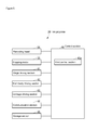
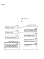
- FIG. 7 is a flowchart of an operation of the computer 60.
- the control section 65 of the computer 60 executes the operation shown in FIG. 7 by activating the program 64a for printing on a three-dimensional object in accordance with an instruction via the operation section 61.
- the image accepting section 65a of the control section 65 receives an image in accordance with an instruction via the operation section 61 (S201).
- the image accepting section 65a can receive an image stored in the storage section 64, or an image received from an external device through the communication section 63 in accordance with an instruction via the operation section 61.
- control section 65 receives various print conditions such as the rotation angle of the shaft members 32 upon printing the image, the range to be printed within the image received in S201, and the like in accordance with an instruction via the operation section 61 (S202).
- control section 65 generates print data based on the image received in S201 and the print conditions received in S202 in accordance with an instruction via the operation section 61 (S203).
- control section 65 sends the print data generated in S203 to the ink jet printer 20 via the communication section 63 (S204), and ends the process shown in FIG. 7 .
- control section 65 may be configured to store the print conditions received in S202 in the storage section 64 so that it can be used again in printing that will take place next or subsequent thereafter.
- the control section 65 of the computer 60 displays a print condition receiving screen 100 shown in FIG. 8 on the display section 62 in accordance with an instruction via the operation section 61.
- FIG. 8 is a diagram showing an example of the print condition receiving screen 100 displayed on the display section 62.
- the print condition receiving screen 100 includes a print image width text box 101a for displaying a length in the main scanning direction shown by the arrow 20a (which is hereafter referred to as "print image width”) among the print image size, and a print image height text box 101b for displaying a length in the sub scanning direction shown by the arrow 20b (which is hereafter referred to as "print image height”) among the print image size.
- a value displayed in the print image width text box 101a is the length in the main scanning direction shown by the arrow 20a of the main surface, the first side surface, and the second side surface of the three-dimensional object 90, which is determined by the length thereof being preliminarily set in the computer 60.
- a value displayed in the print image height text box 101b is a sum of a length in the sub scanning direction shown by the arrow 20b of the main surface of the three-dimensional object 90 attached to the three-dimensional object attaching section 33a in the case where the rotation angle of the shaft member 32 is 0 degrees or 180 degrees, a length in the sub scanning direction shown by the arrow 20b of the first side surface of the three-dimensional object 90 attached to the three-dimensional object attaching section 33a in the case where the rotation angle of the shaft member 32 is 90 degrees or 270 degrees, and a length in the sub scanning direction shown by the arrow 20b of the second side surface of the three-dimensional object 90 attached to the three-dimensional object attaching section 33a in the case where the rotation angle of the shaft member 32 is 90 degrees or 270 degrees, and is determined by the lengths thereof that are preliminarily set to the computer 60.
- the computer 60 may be configured to preliminarily set the various lengths of the three-dimensional object 90 by reading information associated to the types of the designated three-dimensional object 90 from among information in a template data, in a case where the template data including information on the various lengths of the three-dimensional objects 90 in association with types of the three-dimensional objects 90 is stored in the storage section 64 and a type of the three-dimensional object 90 is designated via the operation section 61.
- the print condition receiving screen 100 includes a dividing number spin box 102 for designating a number to divide the print image.
- the number of the setting items is changed in accordance with a designated dividing number in the dividing number spin box 102.
- a default value of the dividing number spin box 102 is preliminarily set in accordance with types of the three-dimensional object 90, and is for example "3".
- the default value may be included in the aforementioned template data.
- the dividing number designated in the dividing number spin box 102 is "3" will be described.
- the print condition receiving screen 100 includes a first divided image height spin box 103a for designating an original length in the sub scanning direction shown by the arrow 20b of a first divided image being a first image included in the print image divided by the dividing number "3" (hereinbelow referred to as a "first divided image original height”), a first divided image angle spin box 103b for designating the designated angle of the rotation of the shaft member 32 in the case where the first divided image is to be printed, a second divided image height text box 103c for displaying the original length in the sub scanning direction shown by the arrow 20b of the second divided image, being a second image included in the print image divided by the dividing number "3" (hereinbelow referred to as a "second divided image original height”), and adjacent to the first divided image, a second divided image angle spin box 103d for designating the designated angle of the rotation of the shaft member 32 in the case where the second divided image is to be printed, a third divided image height spin box 103e for designating the original
- Default values of the first divided image height spin box 103a, the first divided image angle spin box 103b, the second divided image height text box 103c, the second divided image angle spin box 103d, the third divided image height spin box 103e, and the third divided image angle spin box 103f are set preliminarily in accordance with types of the three-dimensional objects 90, which are for example "10", “270", “60”, “0”, “10", and "90". For example, these default values may be included in the aforementioned template data.
- all of the first divided image original height, the second divided image original height, and the third divided image original height are configured changeable by making the values of the first divided image original height and the third divided image original height directly changeable among the first divided image original height, the second divided image original height, and the third divided image original height under the premise that the sum of the first divided image original height, the second divided image original height, and the third divided image original height is equal to the value displayed on the print image height text box 101b, however, the first divided image original height, the second divided image original height, and the third divided image original height may be configured changeable by methods other than the above.
- the value of only one of the first divided image original height and the third divided image original height may be configured directly changeable among the first divided image original height, the second divided image original height, and the third divided image original height.
- the print condition receiving screen 100 includes a first boundary portion height spin box 104a for designating a length (hereinbelow referred to as a "first boundary portion height") in the sub scanning direction shown by the arrow 20b of an overlap in a boundary portion of the first divided image and the second divided image (hereinbelow referred to as a "first boundary portion"), a concentration spin box 104b for designating a concentration of an end of the first boundary portion of the first divided image that overlaps with an end of the second divided image, a concentration spin box 104c for designating a concentration of an end of the first divided image within the first boundary portion of the first divided image, a concentration spin box 104d for designating a concentration of an end of the first boundary portion of the second divided image that overlaps with the first divided image, and a concentration spin box 104e for designating a concentration of an end of the second divided image in the first boundary portion of the second divided image.
- a first boundary portion height spin box 104a for designating a length (hereinbelow
- the concentration spin boxes 104c, 104e can designate only the values that are equal to or less than the concentration spin boxes 104b, 104d, respectively.
- Default values of the first boundary portion height spin box 104a, and the concentration spin boxes 104b, 104c, 104d, 104e are set preliminarily in accordance with types of the three-dimensional objects 90. For example, the default values thereof may be included in the aforementioned template data.
- the print condition receiving screen 100 includes a second boundary portion height spin box 105a for designating a length (hereinbelow referred to as a "second boundary portion height") in the sub scanning direction shown by the arrow 20b of an overlap in a boundary portion of the second divided image and the third divided image (hereinbelow referred to as a "second boundary portion"), a concentration spin box 105b for designating a concentration of an end of the second boundary portion of the second divided image that overlaps with an end of the third divided image, a concentration spin box 105c for designating a concentration of an end of the second divided image within the second boundary portion of the second divided image, a concentration spin box 105d for designating a concentration of an end of the second boundary portion of the third divided image that overlaps with the end of the second divided image, and a concentration spin box 105e for designating a concentration of an end of the third divided image in the second boundary portion of the third divided image.
- a concentration spin box 105b for designating a concentration of an end of the
- the concentration spin boxes 105c, 105e can designate only the values that are equal to or less than the concentration spin boxes 105b, 105d, respectively.
- Default values of the second boundary portion height spin box 105a, and the concentration spin boxes 105b, 105c, 105d, 105e are set preliminarily in accordance with types of the three-dimensional objects 90. For example, these default values may be included in the aforementioned template data.
- the print condition receiving screen 100 includes a preview region 106 that pseudo-displays print contents.
- the preview region 106 includes a print image frame 106a indicating the size of the print image displayed in the print image width text box 101a and the print image height text box 101b, a first boundary center line 106b indicating a center line of the first boundary portion designated in the first divided image height spin box 103a, a second boundary center line 106c indicating a center line of the second boundary portion designated in the third divided image height spin box 103e, and an image 106d that was inputted by a user in S201 of FIG. 7 .
- the user can change position and size of the image 106d in the preview region 106 via the operation section 61 so as to change the part of the image 106d to be fitted in the print image frame 106a.
- the part of the image 106d to be fitted in the print image frame 106a is a part that is to be received by the image accepting section 65a as the print image in the case where the print data is generated in S203 of FIG. 7 .
- the print image received by the image accepting section 65a is divided by the image dividing section 65b, in the case where the print data is generated in S203, in accordance with the various settings in the print condition receiving screen 100 for each of the designated angle designated in the first divided image angle spin box 103b, the designated angle designated in the second divided image angle spin box 103d, and the designated angle designated in the third divided image angle spin box 103f.
- the images divided as above are set as the divided images for each of the designated angles by the image dividing section 65b.
- the divided image for a designated angle is the part within the image received in S201 to be printed by this designated angle.
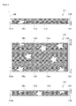
- FIG. 9 is a diagram showing an example of a first divided image 111, a second divided image 112, and a third divided image 113 generated under conditions designated by the print condition receiving screen 100. It should be noted that, in FIG. 9 , broken lines are depicted for the sake of explanation, and are not included in the actual images.
- the first divided image 111 has a length 111a in the sub scanning direction shown by the arrow 20b that is elongated by half the length of the first boundary portion height 114 designated by the first boundary portion height spin box 104a as compared to the first divided image original height 111b designated by the first divided image height spin box 103a.
- the first divided image 111 has its concentration lowered toward the end 111d in the first boundary portion, such that the concentration at an end 111c in the first boundary portion overlapping an end 112d of the second divided image 112 is the concentration designated in the concentration spin box 104b, and the concentration at an end 111d of the first divided image 111 in the first boundary portion is the concentration designated in the concentration spin box 104c.
- the second divided image 112 has a length 112a in the sub scanning direction shown by the arrow 20b that is elongated by the total of half the length of the first boundary portion height 114 designated by the first boundary portion height spin box 104a and half the length of the second boundary portion height 115 designated by the second boundary portion height spin box 105a, as compared to the second divided image original height 112b displayed in the second divided image height text box 103c.
- the second divided image 112 has its concentration lowered toward the end 112d in the first boundary portion, such that the concentration of the end 112c overlapping the end 111d of the first divided image 111 in the first boundary portion is the concentration designated in the concentration spin box 104d, and the concentration at an end 112d of the second divided image 112 in the first boundary portion is the concentration designated in the concentration spin box 104e.
- the second divided image 112 has its concentration lowered toward the end 112f in the second boundary portion, such that the concentration of the end 112e overlapping the end 113d of the third divided image 113 in the second boundary portion is the concentration designated in the concentration spin box 105b, and the concentration at an end 112f of the second divided image 112 in the second boundary portion is the concentration designated in the concentration spin box 105c.
- the third divided image 113 has a length 113a in the sub scanning direction shown by the arrow 20b that is elongated by half the length of the second boundary portion height 115 designated by the second boundary portion height spin box 105a as compared to the third divided image original height 113b designated by the third divided image height spin box 103e.
- the third divided image 113 has its concentration lowered toward the end 113d in the second boundary portion, such that the concentration at an end 113c in the second boundary portion overlapping the end 112f of the second divided image 112 is the concentration designated in the concentration spin box 105d, and the concentration at an end 113d of the third divided image 113 in the second boundary portion is the concentration designated in the concentration spin box 105e.
- each of the divided images realizes the concentration reduction by reducing duty, which is a rate by which dots occupy a section area, that is, by generating spaces between dots.
- the image dividing section 65b can realize the concentration reduction in the boundary portions of the respective divided images by changing the threshold upon binarizing the image data for determining the presence or absence of the dots. Further, as another method, to prevent the occurrence of spaces between dots in the boundary portion of divided images in the image printed on the three-dimensional object 90, the image dividing section 65b can realize the concentration reduction in the boundary portions of the respective divided images so that the spaces between dots can be complemented by the adjacent divided images.
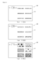
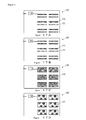
- control section 65 of the computer 60 displays an angle-specific print preview screens 120 shown in FIG. 10A to FIG. 10C on the display section 62 in accordance with instructions via the operation section 61.
- FIG. 10A is a diagram showing an example of the angle-specific print preview screen 120 displayed on the display section 62 in the case where the designated angle is 90 degrees.
- FIG. 10B is a diagram showing an example of the angle-specific print preview screen 120 displayed on the display section 62 in the case where the designated angle is 270 degrees.
- FIG. 10C is a diagram showing an example of the angle-specific print preview screen 120 displayed on the display section 62 in the case where the designated angle is 0 degrees.
- the control section 65 displays the angle-specific print preview screen 120 for the angle selected via the operation section 61 on the display section 62.
- the angle-specific print preview screen 120 can allow the user to recognize how the respective divided images look like in the case of printing on the three-dimensional objects 90 attached to six three-dimensional object supporting sections 33.
- the print condition receiving screen 100 shown in FIG. 8 may include a GUI (Graphical User Interface) for setting whether or not to round off corners for each of four corners of the respective divided images, and setting a radius of the rounded corners.
- GUI Graphic User Interface
- FIG. 11 is a diagram showing an example of the angle-specific print preview screen 120 displayed on the display section 62 in the case where the designated angle is 0 degrees, and is a diagram showing a different example from the example shown in FIG. 11 .
- the second divided image 112 as shown in FIG. 11 is generated. If the corners of print surfaces of the three-dimensional object 90 are rounded corners, when divided images with right angled corners are printed on the print surfaces thereof, ink may be forced out over the corners of the printing surfaces of the three-dimensional object 90 upon printing, whereby the three-dimensional object 90, the three-dimensional object supporting device 30 and the like may be contaminated.
- the possibility that the three-dimensional object 90, the three-dimensional object supporting device 30 and the like are contaminated by the ink forced out from the corners of the printing surfaces of the three-dimensional object 90 upon printing may be reduced by printing the divided images having their corners rounded similarly on the printing surfaces.
- the image accepting section 65a of the control section 65 accepts the print image as aforementioned.
- the image dividing section 65b of the control section 65 divides the print image accepted by the image accepting section 65a in association with each of the designated angles, and sets the divided images to the designated angles, as aforementioned.
- the orthogonal-direction position setting section 65c of the control section 65 sets the orthogonal-direction setting positions to the designated angles.
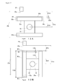
- FIG. 12A is a diagram for explaining a method for setting the orthogonal-direction setting positions by the orthogonal-direction position setting section 65c, and is a side view in a vicinity of the recording heads 25 in the case where the rotation angle of the shaft members 32 is 0 degrees.
- FIG. 12B is a diagram for explaining the method for setting the orthogonal-direction setting positions by the orthogonal-direction position setting section 65c, and is a side view in the vicinity of the recording heads 25 in the case where the rotation angle of the shaft members 32 is 90 degrees.
- a distance 131a in the direction shown by the arrow 20c from a center axis of a shaft member 32 to a nozzle surface 25a of a recording head 25 is a sum of a distance 131b in the direction shown by the arrow 20c from the center axis of the shaft member 32 to an attaching surface of the three-dimensional object attaching section 33a for the main surface 90a of the three-dimensional object 90, a thickness 131c of the main surface part 90a of the three-dimensional object 90 attached to the three-dimensional object attaching section 33a, and a distance 131d in the direction shown by the arrow 20c from the main surface part 90a of the three-dimensional object 90 to the nozzle surface 25a of the recording head 25.
- the distance 131a is a value that is changed in accordance with settings of the orthogonal-direction setting positions. Further, the distance 131b is a constant value in accordance with the three-dimensional object supporting sections 33. Further, since the thickness 131c is one of parameters of the size of the three-dimensional object 90, it is a value that can be inputted via the operation section 61, for example.
- the orthogonal-direction position setting section 65c can suitably set the orthogonal-direction setting positions based on the thickness 131c being one of the parameters of the size of the three-dimensional object 90 inputted from outside, so that the distance 131d in the direction shown by the arrow 20c from the main surface part 90a of the three-dimensional object 90 to the nozzle surface 25a of the recording head 25 becomes a suitable distance for ink flying in the ink jet printer 20 (for example, 2 mm).
- the distance 131a in the direction shown by the arrow 20c from the center axis of the shaft member 32 to the nozzle surface 25a of the recording head 25 is a sum of the distance 132b in the direction shown by the arrow 20c from the center axis of the shaft member 32 to an attaching surface of the three-dimensional object attaching section 33a for the second side surface part 90c of the three-dimensional object 90, a thickness 132c of the second side surface part 90c of the three-dimensional object 90 attached to the three-dimensional object attaching section 33a, and a distance 132d in the direction shown by the arrow 20c from the second side surface part 90c of the three-dimensional object 90 to the nozzle surface 25a of the recording head 25.
- the distance 131a is a value that is changed in accordance with settings of the orthogonal-direction setting positions.
- the distance 132b is a constant value in accordance with the three-dimensional object supporting sections 33.
- the thickness 132c is one of the parameters of the size of the three-dimensional object 90, it is a value that can be inputted via the operation section 61, for example.
- the orthogonal-direction position setting section 65c can suitably set the orthogonal-direction setting positions based on the thickness 132c being one of the parameters of the size of the three-dimensional object 90 inputted from outside, so that the distance 132d in the direction shown by the arrow 20c from the second side surface part 90c of the three-dimensional object 90 to the nozzle surface 25a of the recording head 25 becomes a suitable distance for ink flying in the ink jet printer 20.
- a sum of a distance 132f being half a length 132e in the direction shown by the arrow 20c of the main surface part 90a of the three-dimensional object 90 attached to the three-dimensional object attaching section 33a and the distance 132d can also be regarded as the distance 131a.
- the length 132e is one of the parameters of the size of the three-dimensional object 90, it is a value that can be inputted via the operation section 61, for example.
- the orthogonal-direction position setting section 65c can suitably set the orthogonal-direction setting positions based on the length 132e being one of the parameters of the size of the three-dimensional object 90 inputted from outside so that the distance 132d in the direction shown by the arrow 20c from the second side surface part 90c of the three-dimensional object 90 to the nozzle surface 25a of the recording head 25 becomes a suitable distance for ink flying in the ink jet printer 20.
- the orthogonal-direction position setting section 65c can suitably set the orthogonal-direction setting positions based on the size of the three-dimensional object 90 inputted from outside so that the distance in the direction shown by the arrow 20c from the three-dimensional object 90 to the nozzle surface 25a of the recording head 25 becomes a suitable distance for ink flying in the ink jet printer 20. That is, the orthogonal-direction position setting section 65c can set the orthogonal-direction setting positions for the designated angles based on the size of the three-dimensional object 90 inputted from outside and the designated angles.
- the parallel-direction position setting section 65d of the control section 65 sets the parallel-direction setting position to the designated angles.
- FIG. 13A is a diagram for explaining a method of setting parallel-direction setting positions by the parallel-direction position setting section 65d, and is a side view in the vicinity of the recording head 25 in the case where the angle of rotation of the shaft members 32 is 0 degrees.
- FIG. 13B is a diagram for explaining a method of setting parallel-direction setting positions by the parallel-direction position setting section 65d, and is a side view in the vicinity of the recording head 25 in the case where the angle of rotation of the shaft members 32 is 90 degrees.
- a distance 133a in the sub scanning direction shown by the arrow 20b from an end that is farthest from a center of the nozzle surface 25a of the recording head 25 and the center of the nozzle surface 25a of the recording head 25 in the main surface part 90a of the three-dimensional object 90 in the sub scanning direction shown by the arrow 20b is a sum of a distance 133b in the sub scanning direction shown by the arrow 20b from the center axis of the shaft member 32 to the center of the nozzle surface 25a of the recording head 25, a distance 133c in the sub scanning direction shown by the arrow 20b from the center axis of the shaft member 32 to an attaching surface of the three-dimensional object attaching section 33a for the first side surface part 90b of the three-dimensional object 90, and a thickness 133d of the first side surface part 90b of the three-dimensional object 90 attached to the three-dimensional object attaching section 33a.
- the distance 133b is a value that is changed in accordance with settings of the parallel-direction setting positions. Further, the distance 133c is a constant value in accordance with the three-dimensional object supporting sections 33. Further, since the thickness 133d is one of the parameters of the size of the three-dimensional object 90, it is a value that can be inputted via the operation section 61, for example.
- the parallel-direction position setting section 65d can suitably set the parallel-direction setting positions based on the thickness 133d being one of the parameters of the size of the three-dimensional object 90 inputted from outside, so that the main surface part 90a of the three-dimensional object 90 and the recording heads 25 are suitably positioned in the sub scanning direction shown by the arrow 20b upon printing an image of the main surface of the three-dimensional object 90.
- a sum of a distance 132f being half the length 132e in the sub scanning direction shown by the arrow 20b of the main surface part 90a of the three-dimensional object 90 attached to the three-dimensional object attaching section 33a and the distance 133b can also be regarded as the distance 133a.
- the length 132e is one of the parameters of the size of the three-dimensional object 90, it is a value that can be inputted via the operation section 61, for example.
- the parallel-direction position setting section 65d can suitably set the parallel-direction setting positions based on the length 132e being one of the parameters of the size of the three-dimensional object 90 inputted from outside, so that the main surface part 90a of the three-dimensional object 90 and the recording heads 25 are suitably positioned in the sub scanning direction shown by the arrow 20b upon printing an image of the main surface of the three-dimensional object 90.
- a distance 134a in the sub scanning direction shown by the arrow 20b from the end that is the farthest from the center of the nozzle surface 25a of the recording head 25 and the center of the nozzle surface 25a of the recording head 25 in the second side surface part 90c of the three-dimensional object 90 in the sub scanning direction shown by the arrow 20b is a sum of a distance 133b in the sub scanning direction shown by the arrow 20b from the center axis of the shaft member 32 to the center of the nozzle surface 25a of the recording head 25, a distance 131b from the center axis of the shaft member 32 to an attaching surface of the three-dimensional object attaching section 33a for the main surface part 90a of the three-dimensional object 90, and a thickness 131c of the main surface part 90a of the three-dimensional object 90 attached to the three-dimensional object attaching section 33a.
- the distance 133b is a value that is changed in accordance with settings of the parallel-direction setting positions. Further, the distance 131b is a constant value in accordance with the three-dimensional object supporting sections 33. Further, since the thickness 131c is one of parameters of the size of the three-dimensional object 90, it is a value that can be inputted via the operation section 61, for example.
- the parallel-direction position setting section 65d can suitably set the parallel-direction setting positions based on the thickness 131c being one of the parameters of the size of the three-dimensional object 90 inputted from outside, so that the second side surface part 90c of the three-dimensional object 90 and the recording heads 25 are suitably positioned in the sub scanning direction shown by the arrow 20b upon printing an image on the second side surface of the three-dimensional object 90.
- the parallel-direction position setting section 65d can suitably set the parallel-direction setting positions based on the size of the three-dimensional object 90 inputted from outside, so that the three-dimensional object 90 and the recording heads 25 are suitably positioned in the sub scanning direction shown by the arrow 20b upon printing images on the three-dimensional object 90. That is, the parallel-direction position setting section 65d can set the parallel-direction setting positions for the designated angles based on the size of the three-dimensional object 90 inputted from outside and the designated angles.
- control section 65 In the generation of the print data in S203, the control section 65 generates print data including the divided image set to the designated angle by the image dividing section 65b, the orthogonal-direction setting position set to the designated angle by the orthogonal-direction position setting section 65c, and the parallel-direction setting position set to the designated angle by the parallel-direction position setting section 65d, for each of the designated angles.
- the print control section 46a of the control section 46 of the ink jet printer 20 executes printing on the three-dimensional object 90 based on the print data for each of the designated angles received via the communication section 44.
- the print control section 46a controls the stepping motor 35 so that the rotation angle of the shaft members 32 comes to be the designated angle included in the print data. Due to this, the angle of the three-dimensional objects 90 relative to the nozzle surfaces 25a of the recording heads 25 is changed.
- the print control section 46a controls the stage driving section 41 based on the orthogonal-direction setting position included in the print data to suitably change the relative positions of the recording heads 25 and the three-dimensional object supporting device 30. Accordingly, the distance in the direction shown by the arrow 20c from the three-dimensional object 90 that was preliminarily attached to the three-dimensional object supporting device 30 by the user to the nozzle surfaces 25a of the recording heads 25 becomes a distance suitable for ink flying in the ink jet printer 20.
- the print control section 46a prints the divided image included in the print data, by controlling the recording heads 25, the main body driving section 42, and the carriage driving section 43 based on the print data, on the three-dimensional objects 90 attached to the three-dimensional object supporting device 30.
- the print control section 46a suitably changes the positions of the three-dimensional object 90 and the nozzle surfaces 25a of the recording heads 25 in the sub scanning direction shown by the arrow 20b by controlling the main body driving section 42 while suitably managing the distance in the sub scanning direction shown by the arrow 20b between the three-dimensional objects 90 and the nozzle surfaces 25a of the recording heads 25 based on the parallel-direction setting position included in the print data.
- the print control section 46a sequentially executes the aforementioned series of processes for each of the print data for the designated angles.
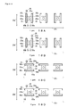
- FIG. 14A is a side view in the vicinity of the recording head 25 in a state where printing is being performed on the three-dimensional object 90 when the angle of rotation of the shaft member 32 is 90 degrees, in the case where the three-dimensional object 90 is attached to only one of the two three-dimensional object attaching sections 33a of the three-dimensional object supporting section 33.
- FIG. 14B is a side view in the vicinity of the recording head 25 in a state where printing is being performed on the three-dimensional object 90 when the angle of rotation of the shaft member 32 is 270 degrees, in the case where the three-dimensional object 90 is attached to only one of the two three-dimensional object attaching sections 33a of the three-dimensional object supporting section 33.
- FIG. 14A is a side view in the vicinity of the recording head 25 in a state where printing is being performed on the three-dimensional object 90 when the angle of rotation of the shaft member 32 is 270 degrees, in the case where the three-dimensional object 90 is attached to only one of the two three-dimensional object attaching sections 33a of the three-dimensional object
- 14C is a side view in the vicinity of the recording head 25 in a state where printing is being performed on the three-dimensional object 90 when the angle of rotation of the shaft member 32 is 0 degrees, in the case where the three-dimensional object 90 is attached to only one of the two three-dimensional object attaching sections 33a of the three-dimensional object supporting section 33.
- the print control section 46a Based on the print data for each of the designated angle, as received via the communication section 44, the print control section 46a performs the printing on the second side surface part 90c of the three-dimensional object 90 in the case where the designated angle is 90 degrees as shown in FIG. 14A , the printing on the first side surface part 90b of the three-dimensional object 90 in the case where the designated angle is 270 degrees as shown in FIG. 14B , and the printing on the main surface part 90a of the three-dimensional object 90 in the case where the designated angle is 0 degrees as shown in FIG. 14C in this order.
- the print control section 46a can improve the print quality on the main surface part 90a can be improved by overwriting on the main surface part 90a by the final printing on the main surface part 90a even if unnecessary ink has adhered to the main surface part 90a by the printing on the second side surface part 90c and the printing on the first side surface part 90b.
- Such an order of printing is useful in improving the print quality of the main surface part 90a, however, it may be changed upon accepting print condition in S202.
- the order of printing may be set preliminarily in the aforementioned order in accordance with the type of the three-dimensional object 90. For example, the order may be included in the aforementioned template data.
- the computer 60 may cause the ink jet printer 20 to print images that are different from one another on the three-dimensional objects 90 attached respectively to the six three-dimensional object supporting sections 33.
- FIG. 15A is a diagram showing an example of the angle-specific print preview screen 120 displayed on the display section 62 in the case where the designated angle is 90 degrees, and is a diagram showing a different example from the example shown in FIG. 10A .
- FIG. 15B is a diagram showing an example of the angle-specific print preview screen 120 displayed on the display section 62 in the case where the designated angle is 270 degrees, and is a diagram showing a different example from the example shown in FIG. 10B .
- FIG. 15C is a diagram showing an example of the angle-specific print preview screen 120 displayed on the display section 62 in the case where the designated angle is 0 degrees, and is a diagram showing an example different from the examples shown in FIG. 10C and FIG. 11 .
- the computer 60 can cause the ink jet printer 20 to print images that are different from one another on the three-dimensional objects 90 attached respectively to the six three-dimensional object supporting sections 33, as shown in FIG. 15A to FIG. 15C .
- Which image is to be printed on which of the three-dimensional objects 90 can be set upon the receipt of the print condition in S202.
- the system 10 for printing on a three-dimensional object can generate a plurality of three-dimensional objects 90 with different designs of images being printed at a time.
- the number of division designated in the dividing number spin box 102 can be a number other than "3".
- FIG. 16A is a side view in the vicinity of the recording head 25 in a state where printing is being performed on the three-dimensional object 90 when the angle of rotation of the shaft member 32 is 45 degrees, in the case where the three-dimensional object 90 is attached to only one of the two three-dimensional object attaching sections 33a of the three-dimensional object supporting section 33.
- FIG. 16B is a side view in the vicinity of the recording head 25 in a state where printing is being performed on the three-dimensional object 90 when the angle of rotation of the shaft member 32 is 315 degrees, in the case where the three-dimensional object 90 is attached to only one of the two three-dimensional object attaching sections 33a of the three-dimensional object supporting section 33.
- the print control section 46a of the control section 46 of the ink jet printer 20 performs, based on the print data for each of the designated angles received via the communication section 44, for example, the printing on the second side surface part 90c of the three-dimensional object 90 in the case where the designated angle is 90 degrees as shown in FIG.
- the system 10 for printing on a three-dimensional object can print images on the three-dimensional objects 90 at more suitable angle with larger number of divisions, so that the print quality on the three-dimensional objects 90 can be improved.
- the printing in the case where the three-dimensional object 90 is attached to only one of the two three-dimensional object attaching sections 33a of the three-dimensional object supporting section 33 has been described.
- the system 10 for printing on a three-dimensional object can perform printing similarly also in the case where the three-dimensional objects 90 are attached to both of the two three-dimensional object attaching sections 33a of the three-dimensional object supporting section 33.
- FIG. 17A is a diagram showing an example of the angle-specific print preview screen 120 displayed on the display section 62 in the case where the designated angle is 90 degrees, and is a diagram showing an example different from the examples shown in FIG. 10A and FIG. 15A .
- FIG. 17B is a diagram showing an example of the angle-specific print preview screen 120 displayed on the display section 62 in the case where the designated angle is 270 degrees, and is a diagram showing an example different from the examples shown in FIG. 10B and FIG. 15B .
- FIG. 17C is a diagram showing an example of the angle-specific print preview screen 120 displayed on the display section 62 in the case where the designated angle is 0 degrees, and is a diagram showing an example different from the examples shown in FIG. 10C , FIG. 11 , and FIG. 15C .
- FIG. 17D is a diagram showing an example of the angle-specific print preview screen 120 displayed on the display section 62 in the case where the designated angle is 180 degrees.
- FIG. 18A is a side view in the vicinity of the recording head 25 in a state where printing is being performed on the three-dimensional object 90 when the angle of rotation of the shaft member 32 is 90 degrees, in the case where the three-dimensional objects 90 are attached to both of the two three-dimensional object attaching sections 33a of the three-dimensional object supporting section 33.
- FIG. 18B is a side view in the vicinity of the recording head 25 in a state where printing is being performed on the three-dimensional object 90 when the angle of rotation of the shaft member 32 is 270 degrees, in the case where the three-dimensional objects 90 are attached to both of the two three-dimensional object attaching sections 33a of the three-dimensional object supporting section 33.
- FIG. 18A is a side view in the vicinity of the recording head 25 in a state where printing is being performed on the three-dimensional object 90 when the angle of rotation of the shaft member 32 is 270 degrees, in the case where the three-dimensional objects 90 are attached to both of the two three-dimensional object attaching sections 33a of the three-dimensional object supporting section 33
- FIG. 18C is a side view in the vicinity of the recording head 25 in a state where printing is being performed on the three-dimensional object 90 when the angle of rotation of the shaft member 32 is 0 degrees, in the case where the three-dimensional objects 90 are attached to both of the two three-dimensional object attaching sections 33a of the three-dimensional object supporting section 33.
- FIG. 18D is a side view in the vicinity of the recording head 25 in a state where printing is being performed on the three-dimensional object 90 when the angle of rotation of the shaft member 32 is 180 degrees, in the case where the three-dimensional objects 90 are attached to both of the two three-dimensional object attaching sections 33a of the three-dimensional object supporting section 33.
- the system 10 for printing on a three-dimensional object sets the print condition for the three-dimensional object 90 attached to one of the two three-dimensional object attaching sections 33a of the three-dimensional object supporting section 33 (hereinbelow referred to as "one-side three-dimensional object”), and as for the print condition for the three-dimensional object 90 attached to the other of the two three-dimensional object attaching sections 33a of the three-dimensional object supporting section 33 (hereinbelow referred to as "other-side three-dimensional object”), a designated angle is set by automatically offsetting the same.
- the divided images to be printed on the one-side three-dimensional object are respectively termed a first divided image 111, a second divided image 112, and a third divided image 113
- the divided images to be printed on the other-side three-dimensional object are respectively termed a first divided image 121, a second divided image 122, a third divided image 123
- the angle-specific print preview screen 120 displayed on the display section 62 in the case where the designated angle is 90 degrees, 270 degrees, 0 degrees, or 180 degrees comes to be as the screens shown in FIG. 17A, FIG. 17B, FIG. 17C, and FIG. 17D .
- FIG. 17A, FIG. 17B, FIG. 17C, and FIG. 17D the screens shown in FIG. 17A, FIG. 17B, FIG. 17C, and FIG. 17D .
- the images to be printed on the one-side three-dimensional objects are configured of the same pattern regardless of the three-dimensional object supporting sections 33, and the images to be printed on the other-side three-dimensional objects are configured of the same pattern regardless of the three-dimensional object supporting sections 33.
- the divided images as shown in FIG. 17A to FIG. 17D are configured of the same pattern regardless of the three-dimensional object supporting sections 33.
- the print control section 46a of the control section 46 of the ink jet printer 20 performs, based on the print data for each of the designated angles received via the communication section 44, for example the printing on the second side surface part 90c of the one-side three-dimensional object 91 and the first side surface part 90b of the other-side three-dimensional object 92 in the case where the designated angle is 90 degrees as shown in FIG. 18A , the printing on the first side surface part 90b of the one-side three-dimensional object 91 and the second side surface part 90c of the other-side three-dimensional object 92 in the case where the designated angle is 270 degrees as shown in FIG.
- the system 10 for printing on a three-dimensional object can print different images on all of the three-dimensional objects 90, or can print images in any arbitrary number of division.
- the system 10 for printing on a three-dimensional object can perform printing on arbitrarily shaped three-dimensional objects.
- FIG. 19 is a side view in the vicinity of the recording head 25 when the angle of rotation of the shaft member 32 is 0 degrees, in a state where a three-dimensional object different from the three-dimensional object 90 shown in FIG. 2 is attached to the three-dimensional object supporting section 33.
- the system 10 for printing on a three-dimensional object can perform printing on a surface 93a of a three-dimensional object 93 that is wholly formed by a curved surface as shown in FIG. 19 .
- the system 10 for printing on a three-dimensional object can perform printing of the divided images that are obtained by dividing the print image by an arbitrary number on the three-dimensional object 93 also in the case of performing printing on the surface 93a of the three-dimensional object 93 that is wholly formed by the curved surface.
- the system 10 for printing on a three-dimensional object of the present invention performs printing by automatically changing the angle of the support of the three-dimensional object 90 with respect to the nozzle surfaces 25a, and the image to be printed on the three-dimensional object 90 in the case where the three-dimensional object 90 is supported by the aforesaid angle with respect to the nozzle surfaces 25a, so that the printing of images from the plurality of directions on the three-dimensional object 90 can be facilitated compared to in the conventional technique.
- system 10 for printing on a three-dimensional object automatically divides the image to be printed on the three-dimensional object 90 with respect to the plurality of designated angles, so that the printing of images from the plurality of directions on the three-dimensional object 90 can be facilitated compared to in the conventional technique.
- FIG. 20 is an outer perspective view of the three-dimensional object 90 in a case where adjacent divided images have been printed apart from each other.
- FIG. 21 is an outer perspective view of the three-dimensional object 90 in a case where boundary portions of the adjacent divided images have been printed while overlapped, in a state where concentration becomes lower toward ends of respective divided images, at the boundary portions of the adjacent divided images.
- the system 10 for printing on a three-dimensional object has a possibility that the adjacent divided images are printed on the three-dimensional object 90 while they are separated as shown in FIG. 20 due to various errors upon printing, whereby an unnatural dividing line 94 may be generated between the adjacent divided images.
- the system 10 for printing on a three-dimensional object can prevent the adjacent divided images from being printed on the three-dimensional object 90 while they are separated due to various errors upon printing, since the boundary portions of the adjacent divided images are printed by being overlapped on the three-dimensional object 90 as shown in FIG. 9 , as a result the generation of the unnatural dividing line 94 between the adjacent divided images can be prevented.
- the system 10 for printing on a three-dimensional object can improve the print quality on the three-dimensional object 90 as shown in FIG. 21 as compared to the configuration in which the respective divided images are printed on the three-dimensional object 90 with the boundary portions of the adjacent divided images not being overlapped.
- FIG. 22 is an outer perspective view of the three-dimensional object 90 in a case where boundary portions of the adjacent divided images have been printed while overlapped, in a state where the concentration is not changed at the boundary portions of the adjacent divided images.
- the system 10 for printing on a three-dimensional object has a possibility that an awkward altering line 95 of images may be generated at overlapped portions among the boundary portions of the adjacent divided images, with the respective divided images being printed on the three-dimensional object 90 in a state where the concentrations of the overlapped portions at the boundary portions of the adjacent divided images become extremely dense than other portions.
- the system 10 for printing on a three-dimensional object prints the respective divided image on the three-dimensional object 90 in the state where the concentration becomes lower toward the end of each divided image at the boundary portions of the adjacent divided images as shown in FIG.
- the system 10 for printing on a three-dimensional object can improve the quality of the printing on the three-dimensional object 90 compared to the configuration in which the respective divided images are printed on the three-dimensional object 90 without the concentration being changed at the boundary portions of the adjacent divided image, as shown in FIG. 21 .
- the relative positions of the recording heads 25 and the three-dimensional object supporting device 30 in the direction orthogonally intersecting the nozzle surfaces 25a, that is, in the direction shown by the arrow 20c, are automatically changed to suitable positions according to the size of the three-dimensional object 90 and the designated angle, so that it can facilitate printing of the images from the plurality of directions on the three-dimensional object 90 compared to the configuration in which the user must input the relative positions of the recording heads 25 and the three-dimensional object supporting device 30 in the direction shown by the arrow 20c for each of the designated angles.
- system 10 for printing on a three-dimensional object may have the configuration in which the relative positions in the direction shown by the arrow 20c of the recording heads 25 and the three-dimensional object supporting device 30 must be inputted by the user for each of the designated angles.
- the relative positions of the recording heads 25 and the three-dimensional object supporting device 30 in the direction parallel to the nozzle surfaces 25a, that is, in the sub scanning direction shown by the arrow 20b, are automatically changed to suitable positions according to the size of the three-dimensional object 90 and the designated angle, so that it can facilitate printing of the images from the plurality of directions on the three-dimensional object 90 compared to the configuration in which the user must input the relative positions of the recording heads 25 and the three-dimensional object supporting device 30 in the sub scanning direction shown by the arrow 20b for each of the designated angles.
- the system 10 for printing on a three-dimensional object may have the configuration in which the relative positions in the sub scanning direction shown by the arrow 20b of the recording heads 25 and the three-dimensional object supporting device 30 must be inputted by the user for each of the designated angles.
- the system 10 for printing on a three-dimensional object in the present embodiment performs printing of the images on the three-dimensional objects 90 by cooperation of the control section 46 of the ink jet printer 20 and the control section 65 of the computer 60.
- the control section 65 of the computer 60 in the present embodiment may be realized by the control section 46 of the ink jet printer 20.
- the ink jet printer 20 is configured to change the relative positions in the direction shown by the arrow 20c of the recording heads 25 and the three-dimensional objects 90 by the movement of the three-dimensional object supporting device 30 relative to the installing section 21a, which is caused by the movement of the supporting device mounting stage 21c relative to the installing section 21a.
- the ink jet printer 20 may be configured to change the relative positions in the direction shown by the arrow 20c of the recording heads 25 and the three-dimensional objects 90 by the movement of the recording heads 25 relative to the installing section 21a.
- the ink jet printer 20 in the present embodiment is a device that prints images by the ultraviolet curable ink, however, it may be a device that prints images by ink other than the ultraviolet curable ink, such as solvent ink or the like.
Landscapes
- Engineering & Computer Science (AREA)
- Manufacturing & Machinery (AREA)
- Theoretical Computer Science (AREA)
- Human Computer Interaction (AREA)
- Physics & Mathematics (AREA)
- General Engineering & Computer Science (AREA)
- General Physics & Mathematics (AREA)
- Record Information Processing For Printing (AREA)
- Coating Apparatus (AREA)
- Ink Jet (AREA)
- Accessory Devices And Overall Control Thereof (AREA)
- Ink Jet Recording Methods And Recording Media Thereof (AREA)
Abstract
Description
- The present invention relates to a system for printing on a three-dimensional object which prints an image on a three-dimensional object.
- Conventionally, an ink jet printer that prints an image on a button used for clothing has been known as a system for printing on a three-dimensional object which prints an image on a three-dimensional object (see Patent Document 1).
- Patent Document 1:
JP 4041470 B - In a case of printing images on a three-dimensional object relatively from a plurality of directions with respect to the three-dimensional object by an ink jet printer, an angle of arrangement of the three-dimensional object relative to the ink jet printer and an image that is to be printed need to be changed by a user each time printing of an image from one direction is completed, and there is a problem regarding the trouble to be taken therefor.
- Further, in a case of generating one series of images on a three-dimensional object by printing each of a plurality of images that are obtained by dividing one image by an ink jet printer on the three-dimensional object relatively from different directions relative to the three-dimensional object, there also is a problem that it is difficult for the user to suitably divide the one image.
- Thus, the present invention aims to provide a system for printing on a three-dimensional object that can facilitate printing of images from a plurality of directions onto the three-dimensional object compared to the conventional technique.
- A system for printing on a three-dimensional object of the present invention includes: a recording head including a nozzle surface on which a nozzle for discharging ink is formed; a three-dimensional object supporting device that supports a three-dimensional object rotatively with a predetermined axis as a center; and a print control section that causes the recording head to print an image on the three-dimensional object while rotating the three-dimensional object by the three-dimensional object supporting device, wherein the print control section causes the three-dimensional object supporting device to support the three-dimensional object at a designated angle, for each of designated angles that are angles being designated, and causes the recording head to print divided images on the three-dimensional object, the divided images being images that are divided from a print image being an image to be printed on the three-dimensional object, the divided images being set with respect to the designated angles, and the system further includes: an image accepting section that accepts the print image; and an image dividing section that divides the print image received by the image accepting section in association with the designated angles to set the divided images to the designated angles.
- According to this configuration, the system for printing on a three-dimensional object of the present invention performs printing by automatically changing the support angle of the three-dimensional object with respect to the nozzle surface, and the image to be printed on the three-dimensional object in the case where the three-dimensional object is supported by the aforesaid angle with respect to the nozzle surface, so that the printing of images from the plurality of directions on the three-dimensional object can be facilitated compared to in the conventional technique. Further, the system for printing on a three-dimensional object of the present invention automatically divides the image to be printed on the three-dimensional object with respect to the plurality of designated angles, so that the printing of images from the plurality of directions on the three-dimensional object can be facilitated compared to in the conventional technique.
- Further, in the system for printing on a three-dimensional object of the present invention, the image dividing section may set the divided images in a state where boundary portions of adjacent divided images are overlapped.
- According to this configuration, the system for printing on a three-dimensional object of the present invention prints the respective divided images on the three-dimensional object while the boundary portions of the adjacent divided images are overlapped, so that the adjacent divided images are prevented from being printed on the three-dimensional object by being apart by various errors upon printing, as a result of which a generation of awkward splits between the adjacent divided images can be prevented. Thus, the system for printing on a three-dimensional object of the present invention can improve quality of the printing on the three-dimensional object compared to a configuration in which the respective divided images are printed on the three-dimensional object without the boundary portions of the adjacent divided images being overlapped.
- Further, in the system for printing on a three-dimensional object of the present invention, the image dividing section may set the divided images in a state where a concentration becomes lower towards an end of each of the divided images at the boundary portions.
- According to this configuration, the system for printing on a three-dimensional object of the present invention prints the respective divided image on the three-dimensional object in the state where the concentration becomes lower toward the end of each divided image at the boundary portions of the adjacent divided images, so that a generation of an awkward altering line of images caused by the concentration being extremely denser at the overlapped portions than at other portions within the boundary portions of the adjacent divided images can be prevented. Accordingly, the system for printing on a three-dimensional object of the present invention can improve the quality of the printing on the three-dimensional object compared to a configuration in which the respective divided images are printed on the three-dimensional object without the concentration being changed at the boundary portions of the adjacent divided images.
- Further, in the system for printing on a three-dimensional object of the present invention, in a case of printing the print image on the three-dimensional object, the print control section may change, for each of the designated angles, orthogonal-direction positions being relative positions of the recording head and the three-dimensional object supporting device in a direction orthogonally intersecting the nozzle surface, to orthogonal-direction setting positions being the orthogonal-direction positions that are set for the designated angle, and the system for printing on a three-dimensional object may include an orthogonal-direction position setting section that sets the orthogonal-direction setting positions for the designated angle based on a size of the three-dimensional object inputted from outside, and the designated angle.
- According to this configuration, in the system for printing on a three-dimensional object of the present invention, the relative positions of the recording head and the three-dimensional object supporting device in the direction orthogonally intersecting the nozzle surface are automatically changed to suitable positions according to the size of the three-dimensional object, and the designated angle, so that it can facilitate printing of the images from the plurality of directions on the three-dimensional object compared to a configuration in which the user must input the relative positions of the recording head and the three-dimensional object supporting device in the direction orthogonally intersecting the nozzle surface for each of the designated angles.
- Further, in the system for printing on a three-dimensional object of the present invention, in a case of printing the print image on the three-dimensional object, the print control section may change, for each of the designated angles, parallel-direction positions being relative positions of the recording head and the three-dimensional object supporting device in a direction parallel to the nozzle surface, to parallel-direction setting positions being the parallel-direction positions that are set for the designated angle, and the system for printing on a three-dimensional object may include a parallel-direction position setting section that sets the parallel-direction setting positions for the designated angle based on a size of the three-dimensional object inputted from outside, and the designated angle.
- According to this configuration, in the system for printing on a three-dimensional object of the present invention, the relative positions of the recording head and the three-dimensional object supporting device in the direction parallel to the nozzle surface are automatically changed to suitable positions according to the size of the three-dimensional object, and the designated angle, so that it can facilitate printing of the images from the plurality of directions on the three-dimensional object compared to a configuration in which the user must input the relative positions of the recording head and the three-dimensional object supporting device in the direction parallel to the nozzle surface for each of the designated angles.
- A program of the present invention for printing on a three-dimensional object is to be executed by a computer that controls an ink jet printer that is provided with: a recording head including a nozzle surface on which a nozzle for discharging ink is formed; a three-dimensional object supporting device that supports the three-dimensional object rotatively with a predetermined axis as a center; and a print control section that causes the recording head to print an image on the three-dimensional object while rotating the three-dimensional object by the three-dimensional object supporting device, wherein the print control section causes the three-dimensional object supporting device to support the three-dimensional object at a designated angle, for each of designated angles that are angles being designated, and causes the recording head to print divided images on the three-dimensional object, the divided images being images that are divided from a print image being an image to be printed on the three-dimensional object, the divided images being set with respect to the designated angles, and the program causes the computer to function as: an image accepting section that accepts the print image; and an image dividing section that divides the print image received by the image accepting section in association with the designated angles to set the divided images to the designated angles.
- According to this configuration, the computer that executes the program for printing on a three-dimensional object of the present invention automatically divides the image to be printed on the three-dimensional object for the plurality of designated angles, so it can facilitate printing of the images from the plurality of directions on the three-dimensional object compared to in the conventional technique.
- The system for printing on a three-dimensional object of the present invention can facilitate printing of the images from the plurality of directions on the three-dimensional object compared to the conventional technique.
-
-
FIG. 1 is a block diagram of a system for printing on a three-dimensional object according to one embodiment of the present invention. -
FIG. 2 is an outer perspective view of the three-dimensional object on which images are printed by an ink jet printer shown inFIG. 1 . -
FIG. 3 is an outer perspective view of the ink jet printer shown inFIG. 1 . -
FIG. 4 is an outer perspective view of a three-dimensional object supporting device shown inFIG. 3 . -
FIG. 5 is a block diagram of the ink jet printer shown inFIG. 3 . -
FIG. 6 is a block diagram of a computer shown inFIG. 1 . -
FIG. 7 is a flowchart of an operation of the computer shown inFIG. 6 . -
FIG. 8 is a diagram showing an example of a print condition receiving screen displayed on a display section shown inFIG. 6 . -
FIG. 9 is a diagram showing an example of a first divided image, a second divided image, and a third divided image that are generated under conditions designated in the print condition receiving screen shown inFIG. 8 . -
FIG. 10A is a diagram showing an example of an angle-specific print preview screen displayed on the display section shown inFIG. 6 in a case where a designated angle is 90 degrees.FIG. 10B is a diagram showing an example of an angle-specific print preview screen displayed on the display section shown inFIG. 6 in a case where the designated angle is 270 degrees.FIG. 10C is a diagram showing an example of an angle-specific print preview screen displayed on the display section shown inFIG. 6 in a case where the designated angle is 0 degrees. -
FIG. 11 is a diagram showing an example of an angle-specific print preview screen displayed on the display section shown inFIG. 6 in the case where the designated angle is 0 degrees, and is a diagram showing an example different from the example shown inFIG. 10C . -
FIG. 12A is a diagram for explaining a method of setting orthogonal-direction setting positions by an orthogonal-direction position setting section shown inFIG. 6 , and is a side view in a vicinity of a recording head in a case where an angle of rotation of a shaft member is 0 degrees.FIG. 12B is a diagram for explaining a method of setting orthogonal-direction setting positions by the orthogonal-direction position setting section shown inFIG. 6 , and is a side view in the vicinity of the recording head in a case where the angle of rotation of the shaft member is 90 degrees. -
FIG. 13A is a diagram for explaining a method of setting parallel-direction setting positions by a parallel-direction position setting section shown inFIG. 6 , and is a side view in the vicinity of the recording head in the case where the angle of rotation of the shaft member is 0 degrees.FIG. 13B is a diagram for explaining the method of setting the parallel-direction setting positions by the parallel-direction position setting section shown inFIG. 6 , and is a side view in the vicinity of the recording head in the case where the angle of rotation of the shaft member is 90 degrees. -
FIG. 14A is a side view in the vicinity of the recording head in a state where printing is performed on the three-dimensional object when the angle of rotation of the shaft member is 90 degrees, in a case where the three-dimensional object is attached to only one of two three-dimensional object attaching sections of a three-dimensional object supporting section shown inFIG. 4 .FIG. 14B is a side view in the vicinity of the recording head in a state where printing is performed on the three-dimensional object when the angle of rotation of the shaft member is 270 degrees, in the case where the three-dimensional object is attached to only one of the two three-dimensional object attaching sections of the three-dimensional object supporting section shown inFIG. 4 .FIG. 14C is a side view in the vicinity of the recording head in a state where printing is performed on the three-dimensional object when the angle of rotation of the shaft member is 0 degrees, in the case where the three-dimensional object is attached to only one of the two three-dimensional object attaching sections of the three-dimensional object supporting section shown inFIG. 4 . -
FIG. 15A is a diagram showing an example of the angle-specific print preview screen displayed on the display section shown inFIG. 6 in the case where the designated angle is 90 degrees, and is a diagram showing an example different from the example shown inFIG. 10A .FIG. 15B is a diagram showing an example of the angle-specific print preview screen displayed on the display section shown inFIG. 6 in the case where the designated angle is 270 degrees, and is a diagram showing an example different from the example shown inFIG. 10B .FIG. 15C is a diagram showing an example of the angle-specific print preview screen displayed on the display section shown inFIG. 6 in the case where the designated angle is 0 degrees, and is a diagram showing an example different from the examples shown inFIG. 10C andFIG. 11 . -
FIG. 16A is a side view in the vicinity of the recording head in a state where printing is being performed on the three-dimensional object when the angle of rotation of the shaft member is 45 degrees, in the case where the three-dimensional object is attached to only one of the two three-dimensional object attaching sections of the three-dimensional object supporting section shown inFIG. 4 .FIG. 16B is a side view in the vicinity of the recording head in a state where printing is being performed on the three-dimensional object when the angle of rotation of the shaft member is 315 degrees, in the case where the three-dimensional object is attached to only one of the two three-dimensional object attaching sections of the three-dimensional object supporting section shown inFIG. 4 . -
FIG. 17A is a diagram showing an example of the angle-specific print preview screen displayed on the display section shown inFIG. 6 in the case where the designated angle is 90 degrees, and is a diagram showing an example different from the examples shown inFIG. 10A andFIG. 15A .FIG. 17B is a diagram showing an example of the angle-specific print preview screen displayed on the display section shown inFIG. 6 in the case where the designated angle is 270 degrees, and is a diagram showing an example different from the examples shown inFIG. 10B andFIG. 15B .FIG. 17C is a diagram showing an example of the angle-specific print preview screen displayed on the display section shown inFIG. 6 in the case where the designated angle is 0 degrees, and is a diagram showing an example different from the examples shown inFIG. 10C ,FIG. 11 , andFIG. 15C .FIG. 17D is a diagram showing an example of the angle-specific print preview screen displayed on the display section shown inFIG. 6 in the case where the designated angle is 180 degrees. -
FIG. 18A is a side view in the vicinity of the recording head in a state where printing is being performed on the three-dimensional object when the angle of rotation of the shaft member is 90 degrees, in a case where the three-dimensional object is attached to both of the two three-dimensional object attaching sections of the three-dimensional object supporting section shown inFIG. 4 .FIG. 18B is a side view in the vicinity of the recording head in a state where printing is being performed on the three-dimensional object when the angle of rotation of the shaft member is 270 degrees, in the case where the three-dimensional object is attached to both of the two three-dimensional object attaching sections of the three-dimensional object supporting section shown inFIG. 4 .FIG. 18C is a side view in the vicinity of the recording head in a state where printing is being performed on the three-dimensional object when the angle of rotation of the shaft member is 0 degrees, in the case where the three-dimensional object is attached to both of the two three-dimensional object attaching sections of the three-dimensional object supporting section shown inFIG. 4 .FIG. 18D is a side view in the vicinity of the recording head in a state where printing is being performed on the three-dimensional object when the angle of rotation of the shaft member is 180 degrees, in the case where the three-dimensional object is attached to both of the two three-dimensional object attaching sections of the three-dimensional object supporting section shown inFIG. 4 . -
FIG. 19 is a side view in the vicinity of the recording head when the angle of rotation of the shaft member shown inFIG. 4 is 0 degrees, in a state where a three-dimensional object different from the three-dimensional object shown inFIG. 2 is attached to the three-dimensional object supporting section. -
FIG. 20 is an outer perspective view of the three-dimensional object shown inFIG. 2 in a case where adjacent divided images are printed apart from each other. -
FIG. 21 is an outer perspective view of the three-dimensional object shown inFIG. 2 in a case of being printed with boundary portions of the adjacent divided images being overlapped, in a state where concentration becomes lower toward ends of respective divided images, at the boundary portions of the adjacent divided images. -
FIG. 22 is an outer perspective view of the three-dimensional object shown inFIG. 2 in a case of being printed with boundary portions of the adjacent divided images being overlapped, in a state where the concentration is not changed, at the boundary portions of the adjacent divided images. - Hereinbelow, an embodiment of the present invention will be described with reference to the drawings.
- Firstly, a configuration of a three-dimensional object printing system according to the present embodiment will be described.
-
FIG. 1 is a block diagram of asystem 10 for printing on a three-dimensional object according to the present embodiment. - As shown in
FIG. 1 , thesystem 10 for printing on a three-dimensional object is provided with anink jet printer 20 that prints an image on a three-dimensional object 90 (seeFIG. 2 ) such as a cover for a portable phone such as a smartphone, and acomputer 60 that inputs print data to theink jet printer 20. Theink jet printer 20 and thecomputer 60 are connected communicably to each other via acable 11 such as a USB (Universal Serial Bus) cable. It should be noted that, theink jet printer 20 and thecomputer 60 may be connected communicably to each other via a network such as a LAN (Local Area Network), Internet, or the like instead of thecable 11. -
FIG. 2 is an outer perspective view of the three-dimensional object 90 on which an image is printed by theink jet printer 20. - As shown in
FIG. 2 , the three-dimensional object 90 includes amain surface part 90a where a main surface, being a primary surface, is formed, a firstside surface part 90b where a first side surface being a surface that is substantially orthogonal to the main surface and continued from the main surface is formed, and a secondside surface part 90c where a second side surface being a surface that is substantially orthogonal to the main surface and continued from the main surface on an opposite side from the first side surface is formed. -
FIG. 3 is an outer perspective view of theink jet printer 20. - As shown in
FIG. 3 , theink jet printer 20 includes a table 21 having an installingsection 21a that is installed on a location of installation such as a floor, amain body 22 extending in a main scanning direction shown by anarrow 20a, and a three-dimensionalobject supporting device 30 that rotatably supports the three-dimensional objects 90 attached to the table 21. - The table 21 includes guiding
mechanisms 21b on both sides in the main scanning direction shown by thearrow 20a, where the guidingmechanisms 21b extending in a sub scanning direction shown by anarrow 20b that orthogonally intersects with the main scanning direction shown by thearrow 20a, and supporting themain body 22 to be movable in the sub scanning direction shown by thearrow 20b. Further, the table 21 includes a supportingdevice mounting stage 21c that mounts thereon the three-dimensionalobject supporting device 30. The supportingdevice mounting stage 21c is movable with respect to theinstalling section 21a, in a direction shown by anarrow 20c, which orthogonally intersects with both the main scanning direction shown by thearrow 20a and the sub scanning direction shown by thearrow 20b. - The
main body 22 includes therein aguide rail 23 extending in the main scanning direction shown by thearrow 20a, and acarriage 24 supported on theguide rail 23 so as to be movable in the main scanning direction shown by thearrow 20a. Thecarriage 24 is mounted with a plurality of recording heads 25 for discharging ultraviolet curable ink in a direction shown by anarrow 20c toward the table 21, and anultraviolet irradiation device 26 such as an LED (Light Emitting Diode) for delivering ultraviolet ray for curing the ultraviolet curable ink discharged by the recording heads 25 toward the table 21. The recording heads 25 includenozzle surfaces 25a where nozzles for discharging ink that are not shown are formed. -
FIG. 4 is an outer perspective view of the three-dimensionalobject supporting device 30. - As shown in
FIG. 4 , the three-dimensionalobject supporting device 30 includes ahousing 31 attached to the supportingdevice mounting stage 21c (seeFIG. 3 ) of the table 21 (seeFIG. 3 ), threeshaft members 32 that are supported in thehousing 31 rotatively, three-dimensionalobject supporting sections 33, two of which are fixed to eachshaft member 32, and that support the three-dimensional objects 90 (seeFIG. 3 ), pulleys 34 fixed to one ends of theshaft members 32, a steppingmotor 35 for generating driving force for theshaft members 32 to rotate, and atiming belt 36 for simultaneously transmitting the driving force of the steppingmotor 35 to the three pulleys 34. - The three
shaft members 32 are arranged to align parallel to each other so that their positions in the direction shown by thearrow 20c are same as one another, and extending in the main scanning direction shown by thearrow 20a. - Each three-dimensional
object supporting section 33 has two three-dimensionalobject attaching sections 33a to which the three-dimensional objects 90 are attached arranged in line symmetry with a center axis of theshaft member 32 as a center. Accordingly, the three-dimensionalobject supporting device 30 can support a total of two three-dimensional objects 90 by one three-dimensionalobject supporting section 33, that is, by two three-dimensionalobject attaching sections 33a; a total of four three-dimensional objects 90 by oneshaft member 32, that is, by two three-dimensionalobject supporting sections 33; and as a whole, that is, a total of twelve three-dimensional objects 90 can be supported by threeshaft members 32. - Hereinbelow, an angle of rotation of the
shaft member 32, in a case where the main surface of the three-dimensional object 90 attached to predetermined one of the two three-dimensionalobject attaching sections 33a of the three-dimensionalobject supporting section 33 is substantially parallel to the nozzle surfaces 25a of the recording heads 25, and the main surface is facing an opposite side from the table 21 side, will be defined as 0 degrees. Further, the angle of rotation of theshaft member 32, in a case where the second side surface of the three-dimensional object 90 attached to the predetermined one of the two three-dimensionalobject attaching sections 33a of the three-dimensionalobject supporting section 33 is substantially parallel to the nozzle surfaces 25a of the recording heads 25, and the second sides surface is facing the opposite side from the table 21 side, while the first side surface of the three-dimensional object 90 attached to the other of the two three-dimensionalobject attaching sections 33a of the three-dimensionalobject supporting section 33 is substantially parallel to the nozzle surfaces 25a of the recording heads 25, and the first side surface is facing the opposite side from the table 21 side, will be defined as 90 degrees. In defining as above, the angle of rotation of theshaft member 32 is 180 degrees in a case where the main surface of the three-dimensional object 90 attached to the other of the two three-dimensionalobject attaching sections 33a of the three-dimensionalobject supporting section 33 is substantially parallel to the nozzle surfaces 25a of the recording heads 25, and the main surface is facing the opposite side from the table 21 side. Further, the angle of rotation of theshaft member 32 is 270 degrees in a case where the first side surface of the three-dimensional object 90 attached to the predetermined one of the two three-dimensionalobject attaching sections 33a of the three-dimensionalobject supporting section 33 is substantially parallel to the nozzle surfaces 25a of the recording heads 25, and the first side surface is facing the opposite side from the table 21 side, while the second side surface of the three-dimensional object 90 attached to the other of the two three-dimensionalobject attaching sections 33a of the three-dimensionalobject supporting section 33 is substantially parallel to the nozzle surfaces 25a of the recording heads 25, and the second side surface is facing the opposite side from the table 21 side. -
FIG. 5 is a block diagram of theink jet printer 20. - As shown in
FIG. 5 , theink jet printer 20 includes the aforementioned recording heads 25 and steppingmotor 35, astage driving section 41 that moves the supportingdevice mounting stage 21c (seeFIG. 3 ) relative to theinstalling section 21a (seeFIG. 3 ), a mainbody driving section 42 that moves the main body 22 (seeFIG. 3 ) in the sub scanning direction shown by thearrow 20b (seeFIG. 3 ) relative to the table 21 (seeFIG. 3 ), acarriage driving section 43 that moves the carriage 24 (seeFIG. 3 ) in the main scanning direction shown by thearrow 20a (seeFIG. 3 ) relative to the guide rail 23 (seeFIG. 3 ), acommunication section 44 that is a communication device for performing communication with external devices such as the computer 60 (seeFIG. 1 ) via the cable 11 (seeFIG. 1 ) or a network, astorage section 45 that is a storage device such as an EEPROM (Electrically Erasable Programmable Read Only Memory) storing various types of data, and acontrol section 46 that controls an entirety of theink jet printer 20. - The
control section 46 includes, for example, a CPU (Central Processing Unit), a ROM (Read Only Memory) that preliminarily stores program and various types of data, and a RAM (Random Access Memory) used as work area for the CPU. The CPU is configured to execute the program stored in the ROM or thestorage section 45. - By executing the program stored in the
storage section 45, thecontrol section 46 functions as aprint control section 46a that causes an image to be printed on the three-dimensional objects 90 by the recording heads 25 while rotating the three-dimensional objects 90 (seeFIG. 3 ) by the three-dimensional object supporting sections 33 (seeFIG. 4 ). Theprint control section 46a has a function to cause a divided image, being an image divided from the print image being the image to be printed on the three-dimensional object 90, that is set to a designated angle, to be printed on the three-dimensional object 90 by the recording heads 25 while causing the three-dimensional object 90 to be supported by the three-dimensionalobject supporting section 33 at the designated angle, for each of the designated angles being angles that are designated. -
FIG. 6 is a block diagram of thecomputer 60. - As shown in
FIG. 6 , thecomputer 60 includes anoperation section 61 being an input device such as a mouse or a keyboard through which various operations are inputted, adisplay section 62 being a display device such as an LCD for displaying various types of information, acommunication section 63 being a communication device that performs communication with external devices such as the ink jet printer 20 (seeFIG. 1 ) through the cable 11 (seeFIG. 1 ) or a network, astorage section 64 being a storage device such as an HDD (Hard Disk Drive) storing program and various types of data, and acontrol section 65 that controls an entirety of thecomputer 60. Thecomputer 60 is configured for example of a computer such as a PC (Personal Computer). - The
storage section 64 stores aprogram 64a for printing on a three-dimensional object being a program for causing theink jet printer 20 to print an image on the three-dimensional object 90 (seeFIG. 3 ). Theprogram 64a for printing on a three-dimensional object may be installed in thecomputer 60 in during the manufacturing process of thecomputer 60, or may be installed additionally to thecomputer 60 from a storage medium such as a CD (Compact Disk), a DVD (Digital Versatile Disk), and the like, or may be installed additionally to thecomputer 60 from a network. - The
control section 65 for example includes a CPU, a ROM that preliminarily stores a program and various types of data, and a RAM used as a work area for the CPU. The CPU is configured to execute the program stored in the ROM or thestorage section 64. - By executing the
program 64a for printing on a three-dimensional object stored in thestorage section 64, thecontrol section 65 functions as animage accepting section 65a that receives a print image, animage dividing section 65b that divides the print image received by theimage accepting section 65a in association with the designated angles to set the divided images to the designated angles, an orthogonal-directionposition setting section 65c that sets orthogonal-direction setting positions, to be set for the designated angles, for the designated angles, which are orthogonal-direction positions being relative positions of the recording heads 25 (seeFIG. 3 ) and the three-dimensional object supporting devices 30 (seeFIG. 3 ) in the direction orthogonally intersecting the nozzle surfaces 25a (seeFIG. 3 ), that is, in the direction shown by thearrow 20c (seeFIG. 3 ), and a parallel-directionposition setting section 65d that sets parallel-direction setting positions, to be set for the designated angles, for the designated angles, which are parallel-direction positions being relative positions of the recording heads 25 and the three-dimensionalobject supporting devices 30 in the direction parallel to the nozzle surfaces 25a, that is, the sub scanning direction shown by thearrow 20b (seeFIG. 3 ). - Next, the operation of the
system 10 for printing on a three-dimensional object will be described. - Firstly, a summary of the flow up to when the print data is sent to the
ink jet printer 20 from thecomputer 60 will be described. -
FIG. 7 is a flowchart of an operation of thecomputer 60. - The
control section 65 of thecomputer 60 executes the operation shown inFIG. 7 by activating theprogram 64a for printing on a three-dimensional object in accordance with an instruction via theoperation section 61. - As shown in
FIG. 7 , theimage accepting section 65a of thecontrol section 65 receives an image in accordance with an instruction via the operation section 61 (S201). For example, theimage accepting section 65a can receive an image stored in thestorage section 64, or an image received from an external device through thecommunication section 63 in accordance with an instruction via theoperation section 61. - Next, the
control section 65 receives various print conditions such as the rotation angle of theshaft members 32 upon printing the image, the range to be printed within the image received in S201, and the like in accordance with an instruction via the operation section 61 (S202). - Next, the
control section 65 generates print data based on the image received in S201 and the print conditions received in S202 in accordance with an instruction via the operation section 61 (S203). - Finally, the
control section 65 sends the print data generated in S203 to theink jet printer 20 via the communication section 63 (S204), and ends the process shown inFIG. 7 . - It should be noted that, the
control section 65 may be configured to store the print conditions received in S202 in thestorage section 64 so that it can be used again in printing that will take place next or subsequent thereafter. - Next, the receipt of the print conditions in S202 will be described in detail.
- The
control section 65 of thecomputer 60 displays a printcondition receiving screen 100 shown inFIG. 8 on thedisplay section 62 in accordance with an instruction via theoperation section 61. -
FIG. 8 is a diagram showing an example of the printcondition receiving screen 100 displayed on thedisplay section 62. - As shown in
FIG. 8 , the printcondition receiving screen 100 includes a print imagewidth text box 101a for displaying a length in the main scanning direction shown by thearrow 20a (which is hereafter referred to as "print image width") among the print image size, and a print imageheight text box 101b for displaying a length in the sub scanning direction shown by thearrow 20b (which is hereafter referred to as "print image height") among the print image size. It should be noted that, a value displayed in the print imagewidth text box 101a is the length in the main scanning direction shown by thearrow 20a of the main surface, the first side surface, and the second side surface of the three-dimensional object 90, which is determined by the length thereof being preliminarily set in thecomputer 60. Further, a value displayed in the print imageheight text box 101b is a sum of a length in the sub scanning direction shown by thearrow 20b of the main surface of the three-dimensional object 90 attached to the three-dimensionalobject attaching section 33a in the case where the rotation angle of theshaft member 32 is 0 degrees or 180 degrees, a length in the sub scanning direction shown by thearrow 20b of the first side surface of the three-dimensional object 90 attached to the three-dimensionalobject attaching section 33a in the case where the rotation angle of theshaft member 32 is 90 degrees or 270 degrees, and a length in the sub scanning direction shown by thearrow 20b of the second side surface of the three-dimensional object 90 attached to the three-dimensionalobject attaching section 33a in the case where the rotation angle of theshaft member 32 is 90 degrees or 270 degrees, and is determined by the lengths thereof that are preliminarily set to thecomputer 60. It should be noted that, thecomputer 60 may be configured to preliminarily set the various lengths of the three-dimensional object 90 by reading information associated to the types of the designated three-dimensional object 90 from among information in a template data, in a case where the template data including information on the various lengths of the three-dimensional objects 90 in association with types of the three-dimensional objects 90 is stored in thestorage section 64 and a type of the three-dimensional object 90 is designated via theoperation section 61. - Further, the print
condition receiving screen 100 includes a dividingnumber spin box 102 for designating a number to divide the print image. In regards to the items of individual settings shown inFIG. 8 , the number of the setting items is changed in accordance with a designated dividing number in the dividingnumber spin box 102. A default value of the dividingnumber spin box 102 is preliminarily set in accordance with types of the three-dimensional object 90, and is for example "3". For example, the default value may be included in the aforementioned template data. Hereinbelow a case where the dividing number designated in the dividingnumber spin box 102 is "3" will be described. - Further, the print condition receiving screen 100 includes a first divided image height spin box 103a for designating an original length in the sub scanning direction shown by the arrow 20b of a first divided image being a first image included in the print image divided by the dividing number "3" (hereinbelow referred to as a "first divided image original height"), a first divided image angle spin box 103b for designating the designated angle of the rotation of the shaft member 32 in the case where the first divided image is to be printed, a second divided image height text box 103c for displaying the original length in the sub scanning direction shown by the arrow 20b of the second divided image, being a second image included in the print image divided by the dividing number "3" (hereinbelow referred to as a "second divided image original height"), and adjacent to the first divided image, a second divided image angle spin box 103d for designating the designated angle of the rotation of the shaft member 32 in the case where the second divided image is to be printed, a third divided image height spin box 103e for designating the original length in the sub scanning direction shown by the arrow 20b of the third divided image, being a third image included in the print image divided by the dividing number "3" (hereinbelow referred to as a "third divided image original height"), and adjacent to the second divided image, and a third divided image angle spin box 103f for designating the designated angle of the rotation of the shaft member 32 in the case where the third divided image is to be printed. Default values of the first divided image
height spin box 103a, the first divided imageangle spin box 103b, the second divided imageheight text box 103c, the second divided imageangle spin box 103d, the third divided imageheight spin box 103e, and the third divided imageangle spin box 103f are set preliminarily in accordance with types of the three-dimensional objects 90, which are for example "10", "270", "60", "0", "10", and "90". For example, these default values may be included in the aforementioned template data. - It should be noted that, in the print
condition receiving screen 100 shown inFIG. 8 , all of the first divided image original height, the second divided image original height, and the third divided image original height are configured changeable by making the values of the first divided image original height and the third divided image original height directly changeable among the first divided image original height, the second divided image original height, and the third divided image original height under the premise that the sum of the first divided image original height, the second divided image original height, and the third divided image original height is equal to the value displayed on the print imageheight text box 101b, however, the first divided image original height, the second divided image original height, and the third divided image original height may be configured changeable by methods other than the above. For example, if there is the premise that the first divided image original height and the third divided image original height are equal in the three-dimensional object 90, the value of only one of the first divided image original height and the third divided image original height may be configured directly changeable among the first divided image original height, the second divided image original height, and the third divided image original height. - The print
condition receiving screen 100 includes a first boundary portionheight spin box 104a for designating a length (hereinbelow referred to as a "first boundary portion height") in the sub scanning direction shown by thearrow 20b of an overlap in a boundary portion of the first divided image and the second divided image (hereinbelow referred to as a "first boundary portion"), aconcentration spin box 104b for designating a concentration of an end of the first boundary portion of the first divided image that overlaps with an end of the second divided image, aconcentration spin box 104c for designating a concentration of an end of the first divided image within the first boundary portion of the first divided image, aconcentration spin box 104d for designating a concentration of an end of the first boundary portion of the second divided image that overlaps with the first divided image, and aconcentration spin box 104e for designating a concentration of an end of the second divided image in the first boundary portion of the second divided image. Theconcentration spin boxes concentration spin boxes height spin box 104a, and theconcentration spin boxes dimensional objects 90. For example, the default values thereof may be included in the aforementioned template data. - The print
condition receiving screen 100 includes a second boundary portionheight spin box 105a for designating a length (hereinbelow referred to as a "second boundary portion height") in the sub scanning direction shown by thearrow 20b of an overlap in a boundary portion of the second divided image and the third divided image (hereinbelow referred to as a "second boundary portion"), aconcentration spin box 105b for designating a concentration of an end of the second boundary portion of the second divided image that overlaps with an end of the third divided image, aconcentration spin box 105c for designating a concentration of an end of the second divided image within the second boundary portion of the second divided image, aconcentration spin box 105d for designating a concentration of an end of the second boundary portion of the third divided image that overlaps with the end of the second divided image, and aconcentration spin box 105e for designating a concentration of an end of the third divided image in the second boundary portion of the third divided image. Theconcentration spin boxes concentration spin boxes height spin box 105a, and theconcentration spin boxes dimensional objects 90. For example, these default values may be included in the aforementioned template data. - Further, the print
condition receiving screen 100 includes apreview region 106 that pseudo-displays print contents. Thepreview region 106 includes aprint image frame 106a indicating the size of the print image displayed in the print imagewidth text box 101a and the print imageheight text box 101b, a firstboundary center line 106b indicating a center line of the first boundary portion designated in the first divided imageheight spin box 103a, a secondboundary center line 106c indicating a center line of the second boundary portion designated in the third divided imageheight spin box 103e, and animage 106d that was inputted by a user in S201 ofFIG. 7 . The user can change position and size of theimage 106d in thepreview region 106 via theoperation section 61 so as to change the part of theimage 106d to be fitted in theprint image frame 106a. - The part of the
image 106d to be fitted in theprint image frame 106a is a part that is to be received by theimage accepting section 65a as the print image in the case where the print data is generated in S203 ofFIG. 7 . Here, the print image received by theimage accepting section 65a is divided by theimage dividing section 65b, in the case where the print data is generated in S203, in accordance with the various settings in the printcondition receiving screen 100 for each of the designated angle designated in the first divided imageangle spin box 103b, the designated angle designated in the second divided imageangle spin box 103d, and the designated angle designated in the third divided imageangle spin box 103f. Further, the images divided as above are set as the divided images for each of the designated angles by theimage dividing section 65b. The divided image for a designated angle is the part within the image received in S201 to be printed by this designated angle. -
FIG. 9 is a diagram showing an example of a first dividedimage 111, a second dividedimage 112, and a thirddivided image 113 generated under conditions designated by the printcondition receiving screen 100. It should be noted that, inFIG. 9 , broken lines are depicted for the sake of explanation, and are not included in the actual images. - As shown in
FIG. 9 , the first dividedimage 111 has alength 111a in the sub scanning direction shown by thearrow 20b that is elongated by half the length of the firstboundary portion height 114 designated by the first boundary portionheight spin box 104a as compared to the first divided imageoriginal height 111b designated by the first divided imageheight spin box 103a. The first dividedimage 111 has its concentration lowered toward theend 111d in the first boundary portion, such that the concentration at anend 111c in the first boundary portion overlapping anend 112d of the second dividedimage 112 is the concentration designated in theconcentration spin box 104b, and the concentration at anend 111d of the first dividedimage 111 in the first boundary portion is the concentration designated in theconcentration spin box 104c. - The second divided
image 112 has alength 112a in the sub scanning direction shown by thearrow 20b that is elongated by the total of half the length of the firstboundary portion height 114 designated by the first boundary portionheight spin box 104a and half the length of the secondboundary portion height 115 designated by the second boundary portionheight spin box 105a, as compared to the second divided imageoriginal height 112b displayed in the second divided imageheight text box 103c. The second dividedimage 112 has its concentration lowered toward theend 112d in the first boundary portion, such that the concentration of theend 112c overlapping theend 111d of the first dividedimage 111 in the first boundary portion is the concentration designated in theconcentration spin box 104d, and the concentration at anend 112d of the second dividedimage 112 in the first boundary portion is the concentration designated in theconcentration spin box 104e. The second dividedimage 112 has its concentration lowered toward theend 112f in the second boundary portion, such that the concentration of theend 112e overlapping theend 113d of the thirddivided image 113 in the second boundary portion is the concentration designated in theconcentration spin box 105b, and the concentration at anend 112f of the second dividedimage 112 in the second boundary portion is the concentration designated in theconcentration spin box 105c. - The third
divided image 113 has alength 113a in the sub scanning direction shown by thearrow 20b that is elongated by half the length of the secondboundary portion height 115 designated by the second boundary portionheight spin box 105a as compared to the third divided imageoriginal height 113b designated by the third divided imageheight spin box 103e. The thirddivided image 113 has its concentration lowered toward theend 113d in the second boundary portion, such that the concentration at anend 113c in the second boundary portion overlapping theend 112f of the second dividedimage 112 is the concentration designated in theconcentration spin box 105d, and the concentration at anend 113d of the thirddivided image 113 in the second boundary portion is the concentration designated in theconcentration spin box 105e. - It should be noted that, in the case of lowering the concentration at the boundary portion, each of the divided images realizes the concentration reduction by reducing duty, which is a rate by which dots occupy a section area, that is, by generating spaces between dots. The
image dividing section 65b can realize the concentration reduction in the boundary portions of the respective divided images by changing the threshold upon binarizing the image data for determining the presence or absence of the dots. Further, as another method, to prevent the occurrence of spaces between dots in the boundary portion of divided images in the image printed on the three-dimensional object 90, theimage dividing section 65b can realize the concentration reduction in the boundary portions of the respective divided images so that the spaces between dots can be complemented by the adjacent divided images. In the case of realizing the concentration reduction in the boundary portions so as to complement the spaces between dots by the adjacent divided images, when the total of the concentration in the boundary portions in the respective divided images exceeds 100%, various methods, such as a method to increase dots for pixels with dark color such as black or cyan in the image, a method to increase dots for random pixels in the image, and the like can be employed as a method of arranging the dots at the portion exceeding 100%. - In a case where the
program 64a for printing on a three-dimensional object is being activated, thecontrol section 65 of thecomputer 60 displays an angle-specific print preview screens 120 shown inFIG. 10A to FIG. 10C on thedisplay section 62 in accordance with instructions via theoperation section 61. -
FIG. 10A is a diagram showing an example of the angle-specificprint preview screen 120 displayed on thedisplay section 62 in the case where the designated angle is 90 degrees.FIG. 10B is a diagram showing an example of the angle-specificprint preview screen 120 displayed on thedisplay section 62 in the case where the designated angle is 270 degrees.FIG. 10C is a diagram showing an example of the angle-specificprint preview screen 120 displayed on thedisplay section 62 in the case where the designated angle is 0 degrees. - Of the designated angle that is designated in the first divided image
angle spin box 103b, the designated angle that is designated in the second divided imageangle spin box 103d, and the designated angle that is designated in the third divided imageangle spin box 103f, thecontrol section 65 displays the angle-specificprint preview screen 120 for the angle selected via theoperation section 61 on thedisplay section 62. The angle-specificprint preview screen 120 can allow the user to recognize how the respective divided images look like in the case of printing on the three-dimensional objects 90 attached to six three-dimensionalobject supporting sections 33. - It should be noted that, the print
condition receiving screen 100 shown inFIG. 8 may include a GUI (Graphical User Interface) for setting whether or not to round off corners for each of four corners of the respective divided images, and setting a radius of the rounded corners. -
FIG. 11 is a diagram showing an example of the angle-specificprint preview screen 120 displayed on thedisplay section 62 in the case where the designated angle is 0 degrees, and is a diagram showing a different example from the example shown inFIG. 11 . - For example, in the case of being set to round off the four corners of the second divided
image 112, in the generation of the print data in S203 ofFIG. 7 , the second dividedimage 112 as shown inFIG. 11 is generated. If the corners of print surfaces of the three-dimensional object 90 are rounded corners, when divided images with right angled corners are printed on the print surfaces thereof, ink may be forced out over the corners of the printing surfaces of the three-dimensional object 90 upon printing, whereby the three-dimensional object 90, the three-dimensionalobject supporting device 30 and the like may be contaminated. However, in the case where the corners of the printing surfaces of the three-dimensional object 90 are rounded, the possibility that the three-dimensional object 90, the three-dimensionalobject supporting device 30 and the like are contaminated by the ink forced out from the corners of the printing surfaces of the three-dimensional object 90 upon printing may be reduced by printing the divided images having their corners rounded similarly on the printing surfaces. - Next, the generation of the print data in S203 of
FIG. 7 will be described. - In the generation of the print data in S203, the
image accepting section 65a of thecontrol section 65 accepts the print image as aforementioned. - Further, in the generation of the print data in S203, the
image dividing section 65b of thecontrol section 65 divides the print image accepted by theimage accepting section 65a in association with each of the designated angles, and sets the divided images to the designated angles, as aforementioned. - Further, in the generation of the print data in S203, the orthogonal-direction
position setting section 65c of thecontrol section 65 sets the orthogonal-direction setting positions to the designated angles. -
FIG. 12A is a diagram for explaining a method for setting the orthogonal-direction setting positions by the orthogonal-directionposition setting section 65c, and is a side view in a vicinity of the recording heads 25 in the case where the rotation angle of theshaft members 32 is 0 degrees.FIG. 12B is a diagram for explaining the method for setting the orthogonal-direction setting positions by the orthogonal-directionposition setting section 65c, and is a side view in the vicinity of the recording heads 25 in the case where the rotation angle of theshaft members 32 is 90 degrees. - As shown in
FIG. 12A , in the case where the rotation angle of theshaft members 32 is 0 degrees, adistance 131a in the direction shown by thearrow 20c from a center axis of ashaft member 32 to anozzle surface 25a of arecording head 25 is a sum of adistance 131b in the direction shown by thearrow 20c from the center axis of theshaft member 32 to an attaching surface of the three-dimensionalobject attaching section 33a for themain surface 90a of the three-dimensional object 90, athickness 131c of themain surface part 90a of the three-dimensional object 90 attached to the three-dimensionalobject attaching section 33a, and adistance 131d in the direction shown by thearrow 20c from themain surface part 90a of the three-dimensional object 90 to thenozzle surface 25a of therecording head 25. Here, thedistance 131a is a value that is changed in accordance with settings of the orthogonal-direction setting positions. Further, thedistance 131b is a constant value in accordance with the three-dimensionalobject supporting sections 33. Further, since thethickness 131c is one of parameters of the size of the three-dimensional object 90, it is a value that can be inputted via theoperation section 61, for example. Accordingly, in the case where the rotation angle of theshaft members 32 is 0 degrees, the orthogonal-directionposition setting section 65c can suitably set the orthogonal-direction setting positions based on thethickness 131c being one of the parameters of the size of the three-dimensional object 90 inputted from outside, so that thedistance 131d in the direction shown by thearrow 20c from themain surface part 90a of the three-dimensional object 90 to thenozzle surface 25a of therecording head 25 becomes a suitable distance for ink flying in the ink jet printer 20 (for example, 2 mm). - Further, as shown in
FIG. 12B , in the case where the rotation angle of theshaft members 32 is 90 degrees, thedistance 131a in the direction shown by thearrow 20c from the center axis of theshaft member 32 to thenozzle surface 25a of therecording head 25 is a sum of thedistance 132b in the direction shown by thearrow 20c from the center axis of theshaft member 32 to an attaching surface of the three-dimensionalobject attaching section 33a for the secondside surface part 90c of the three-dimensional object 90, athickness 132c of the secondside surface part 90c of the three-dimensional object 90 attached to the three-dimensionalobject attaching section 33a, and adistance 132d in the direction shown by thearrow 20c from the secondside surface part 90c of the three-dimensional object 90 to thenozzle surface 25a of therecording head 25. Here, thedistance 131a is a value that is changed in accordance with settings of the orthogonal-direction setting positions. Further, thedistance 132b is a constant value in accordance with the three-dimensionalobject supporting sections 33. Further, since thethickness 132c is one of the parameters of the size of the three-dimensional object 90, it is a value that can be inputted via theoperation section 61, for example. Accordingly, in the case where the rotation angle of theshaft members 32 is 90 degrees, the orthogonal-directionposition setting section 65c can suitably set the orthogonal-direction setting positions based on thethickness 132c being one of the parameters of the size of the three-dimensional object 90 inputted from outside, so that thedistance 132d in the direction shown by thearrow 20c from the secondside surface part 90c of the three-dimensional object 90 to thenozzle surface 25a of therecording head 25 becomes a suitable distance for ink flying in theink jet printer 20. It should be noted that in the case where the rotation angle of theshaft members 32 is 90 degrees, a sum of adistance 132f being half alength 132e in the direction shown by thearrow 20c of themain surface part 90a of the three-dimensional object 90 attached to the three-dimensionalobject attaching section 33a and thedistance 132d can also be regarded as thedistance 131a. Here, since thelength 132e is one of the parameters of the size of the three-dimensional object 90, it is a value that can be inputted via theoperation section 61, for example. Accordingly, in the case where the rotation angle of theshaft members 32 is 90 degrees, the orthogonal-directionposition setting section 65c can suitably set the orthogonal-direction setting positions based on thelength 132e being one of the parameters of the size of the three-dimensional object 90 inputted from outside so that thedistance 132d in the direction shown by thearrow 20c from the secondside surface part 90c of the three-dimensional object 90 to thenozzle surface 25a of therecording head 25 becomes a suitable distance for ink flying in theink jet printer 20. - In the above, the case where the rotation angle of the
shaft members 32 is 0 degrees and the case where the rotation angle of theshaft members 32 is 90 degrees have been described. However, similarly, also in cases where the rotation angle of theshaft members 32 is an angle other than 0 degrees or 90 degrees, the orthogonal-directionposition setting section 65c can suitably set the orthogonal-direction setting positions based on the size of the three-dimensional object 90 inputted from outside so that the distance in the direction shown by thearrow 20c from the three-dimensional object 90 to thenozzle surface 25a of therecording head 25 becomes a suitable distance for ink flying in theink jet printer 20. That is, the orthogonal-directionposition setting section 65c can set the orthogonal-direction setting positions for the designated angles based on the size of the three-dimensional object 90 inputted from outside and the designated angles. - In the generation of the print data in S203, the parallel-direction
position setting section 65d of thecontrol section 65 sets the parallel-direction setting position to the designated angles. -
FIG. 13A is a diagram for explaining a method of setting parallel-direction setting positions by the parallel-directionposition setting section 65d, and is a side view in the vicinity of therecording head 25 in the case where the angle of rotation of theshaft members 32 is 0 degrees.FIG. 13B is a diagram for explaining a method of setting parallel-direction setting positions by the parallel-directionposition setting section 65d, and is a side view in the vicinity of therecording head 25 in the case where the angle of rotation of theshaft members 32 is 90 degrees. - As shown in
FIG. 13A , in the case where the rotation angle of theshaft members 32 is 0 degrees, adistance 133a in the sub scanning direction shown by thearrow 20b from an end that is farthest from a center of thenozzle surface 25a of therecording head 25 and the center of thenozzle surface 25a of therecording head 25 in themain surface part 90a of the three-dimensional object 90 in the sub scanning direction shown by thearrow 20b is a sum of adistance 133b in the sub scanning direction shown by thearrow 20b from the center axis of theshaft member 32 to the center of thenozzle surface 25a of therecording head 25, adistance 133c in the sub scanning direction shown by thearrow 20b from the center axis of theshaft member 32 to an attaching surface of the three-dimensionalobject attaching section 33a for the firstside surface part 90b of the three-dimensional object 90, and athickness 133d of the firstside surface part 90b of the three-dimensional object 90 attached to the three-dimensionalobject attaching section 33a. Here, thedistance 133b is a value that is changed in accordance with settings of the parallel-direction setting positions. Further, thedistance 133c is a constant value in accordance with the three-dimensionalobject supporting sections 33. Further, since thethickness 133d is one of the parameters of the size of the three-dimensional object 90, it is a value that can be inputted via theoperation section 61, for example. Accordingly, in the case where the rotation angle of theshaft members 32 is 0 degrees, the parallel-directionposition setting section 65d can suitably set the parallel-direction setting positions based on thethickness 133d being one of the parameters of the size of the three-dimensional object 90 inputted from outside, so that themain surface part 90a of the three-dimensional object 90 and the recording heads 25 are suitably positioned in the sub scanning direction shown by thearrow 20b upon printing an image of the main surface of the three-dimensional object 90. It should be noted that in the case where the rotation angle of theshaft members 32 is 0 degrees, a sum of adistance 132f being half thelength 132e in the sub scanning direction shown by thearrow 20b of themain surface part 90a of the three-dimensional object 90 attached to the three-dimensionalobject attaching section 33a and thedistance 133b can also be regarded as thedistance 133a. Here, since thelength 132e is one of the parameters of the size of the three-dimensional object 90, it is a value that can be inputted via theoperation section 61, for example. Accordingly, in the case where the rotation angle of theshaft members 32 is 0 degrees, the parallel-directionposition setting section 65d can suitably set the parallel-direction setting positions based on thelength 132e being one of the parameters of the size of the three-dimensional object 90 inputted from outside, so that themain surface part 90a of the three-dimensional object 90 and the recording heads 25 are suitably positioned in the sub scanning direction shown by thearrow 20b upon printing an image of the main surface of the three-dimensional object 90. - As shown in
FIG. 13B , in the case where the rotation angle of theshaft members 32 is 90 degrees, adistance 134a in the sub scanning direction shown by thearrow 20b from the end that is the farthest from the center of thenozzle surface 25a of therecording head 25 and the center of thenozzle surface 25a of therecording head 25 in the secondside surface part 90c of the three-dimensional object 90 in the sub scanning direction shown by thearrow 20b is a sum of adistance 133b in the sub scanning direction shown by thearrow 20b from the center axis of theshaft member 32 to the center of thenozzle surface 25a of therecording head 25, adistance 131b from the center axis of theshaft member 32 to an attaching surface of the three-dimensionalobject attaching section 33a for themain surface part 90a of the three-dimensional object 90, and athickness 131c of themain surface part 90a of the three-dimensional object 90 attached to the three-dimensionalobject attaching section 33a. Here, thedistance 133b is a value that is changed in accordance with settings of the parallel-direction setting positions. Further, thedistance 131b is a constant value in accordance with the three-dimensionalobject supporting sections 33. Further, since thethickness 131c is one of parameters of the size of the three-dimensional object 90, it is a value that can be inputted via theoperation section 61, for example. Accordingly, in the case where the rotation angle of theshaft members 32 is 90 degrees, the parallel-directionposition setting section 65d can suitably set the parallel-direction setting positions based on thethickness 131c being one of the parameters of the size of the three-dimensional object 90 inputted from outside, so that the secondside surface part 90c of the three-dimensional object 90 and the recording heads 25 are suitably positioned in the sub scanning direction shown by thearrow 20b upon printing an image on the second side surface of the three-dimensional object 90. - In the above, the case where the rotation angle of the
shaft members 32 is 0 degrees and the case where the rotation angle of theshaft members 32 is 90 degrees have been described. However, similarly, also for cases where the rotation angle of theshaft members 32 is an angle other than 0 degrees or 90 degrees, the parallel-directionposition setting section 65d can suitably set the parallel-direction setting positions based on the size of the three-dimensional object 90 inputted from outside, so that the three-dimensional object 90 and the recording heads 25 are suitably positioned in the sub scanning direction shown by thearrow 20b upon printing images on the three-dimensional object 90. That is, the parallel-directionposition setting section 65d can set the parallel-direction setting positions for the designated angles based on the size of the three-dimensional object 90 inputted from outside and the designated angles. - In the generation of the print data in S203, the
control section 65 generates print data including the divided image set to the designated angle by theimage dividing section 65b, the orthogonal-direction setting position set to the designated angle by the orthogonal-directionposition setting section 65c, and the parallel-direction setting position set to the designated angle by the parallel-directionposition setting section 65d, for each of the designated angles. - Next, an operation of the
ink jet printer 20 in the case of executing print on the three-dimensional object 90 based on the print data sent from thecomputer 60 will be described. - The
print control section 46a of thecontrol section 46 of theink jet printer 20 executes printing on the three-dimensional object 90 based on the print data for each of the designated angles received via thecommunication section 44. - Firstly, the
print control section 46a controls the steppingmotor 35 so that the rotation angle of theshaft members 32 comes to be the designated angle included in the print data. Due to this, the angle of the three-dimensional objects 90 relative to the nozzle surfaces 25a of the recording heads 25 is changed. - Next, the
print control section 46a controls thestage driving section 41 based on the orthogonal-direction setting position included in the print data to suitably change the relative positions of the recording heads 25 and the three-dimensionalobject supporting device 30. Accordingly, the distance in the direction shown by thearrow 20c from the three-dimensional object 90 that was preliminarily attached to the three-dimensionalobject supporting device 30 by the user to the nozzle surfaces 25a of the recording heads 25 becomes a distance suitable for ink flying in theink jet printer 20. - Next, the
print control section 46a prints the divided image included in the print data, by controlling the recording heads 25, the mainbody driving section 42, and thecarriage driving section 43 based on the print data, on the three-dimensional objects 90 attached to the three-dimensionalobject supporting device 30. Here, theprint control section 46a suitably changes the positions of the three-dimensional object 90 and the nozzle surfaces 25a of the recording heads 25 in the sub scanning direction shown by thearrow 20b by controlling the mainbody driving section 42 while suitably managing the distance in the sub scanning direction shown by thearrow 20b between the three-dimensional objects 90 and the nozzle surfaces 25a of the recording heads 25 based on the parallel-direction setting position included in the print data. - The
print control section 46a sequentially executes the aforementioned series of processes for each of the print data for the designated angles. -
FIG. 14A is a side view in the vicinity of therecording head 25 in a state where printing is being performed on the three-dimensional object 90 when the angle of rotation of theshaft member 32 is 90 degrees, in the case where the three-dimensional object 90 is attached to only one of the two three-dimensionalobject attaching sections 33a of the three-dimensionalobject supporting section 33.FIG. 14B is a side view in the vicinity of therecording head 25 in a state where printing is being performed on the three-dimensional object 90 when the angle of rotation of theshaft member 32 is 270 degrees, in the case where the three-dimensional object 90 is attached to only one of the two three-dimensionalobject attaching sections 33a of the three-dimensionalobject supporting section 33.FIG. 14C is a side view in the vicinity of therecording head 25 in a state where printing is being performed on the three-dimensional object 90 when the angle of rotation of theshaft member 32 is 0 degrees, in the case where the three-dimensional object 90 is attached to only one of the two three-dimensionalobject attaching sections 33a of the three-dimensionalobject supporting section 33. - Based on the print data for each of the designated angle, as received via the
communication section 44, theprint control section 46a performs the printing on the secondside surface part 90c of the three-dimensional object 90 in the case where the designated angle is 90 degrees as shown inFIG. 14A , the printing on the firstside surface part 90b of the three-dimensional object 90 in the case where the designated angle is 270 degrees as shown inFIG. 14B , and the printing on themain surface part 90a of the three-dimensional object 90 in the case where the designated angle is 0 degrees as shown inFIG. 14C in this order. Accordingly, by executing the printing on themain surface part 90a lastly, theprint control section 46a can improve the print quality on themain surface part 90a can be improved by overwriting on themain surface part 90a by the final printing on themain surface part 90a even if unnecessary ink has adhered to themain surface part 90a by the printing on the secondside surface part 90c and the printing on the firstside surface part 90b. Such an order of printing is useful in improving the print quality of themain surface part 90a, however, it may be changed upon accepting print condition in S202. The order of printing may be set preliminarily in the aforementioned order in accordance with the type of the three-dimensional object 90. For example, the order may be included in the aforementioned template data. - In the above, the example in which a same image is printed on each of the three-
dimensional objects 90 attached respectively to the six three-dimensionalobject supporting sections 33 has been described. However, in a case of receiving a plurality of images in S201, thecomputer 60 may cause theink jet printer 20 to print images that are different from one another on the three-dimensional objects 90 attached respectively to the six three-dimensionalobject supporting sections 33. -
FIG. 15A is a diagram showing an example of the angle-specificprint preview screen 120 displayed on thedisplay section 62 in the case where the designated angle is 90 degrees, and is a diagram showing a different example from the example shown inFIG. 10A .FIG. 15B is a diagram showing an example of the angle-specificprint preview screen 120 displayed on thedisplay section 62 in the case where the designated angle is 270 degrees, and is a diagram showing a different example from the example shown inFIG. 10B .FIG. 15C is a diagram showing an example of the angle-specificprint preview screen 120 displayed on thedisplay section 62 in the case where the designated angle is 0 degrees, and is a diagram showing an example different from the examples shown inFIG. 10C andFIG. 11 . - In the case of receiving a plurality of images in S201, the
computer 60 can cause theink jet printer 20 to print images that are different from one another on the three-dimensional objects 90 attached respectively to the six three-dimensionalobject supporting sections 33, as shown inFIG. 15A to FIG. 15C . Which image is to be printed on which of the three-dimensional objects 90 can be set upon the receipt of the print condition in S202. In the case of printing the images that are different from one another on the three-dimensional objects 90 attached respectively to the six three-dimensionalobject supporting sections 33, thesystem 10 for printing on a three-dimensional object can generate a plurality of three-dimensional objects 90 with different designs of images being printed at a time. - In the above, the printing in the case where the number of division is "3" in the dividing
number spin box 102 has been described. However, the number of division designated in the dividingnumber spin box 102 can be a number other than "3". -
FIG. 16A is a side view in the vicinity of therecording head 25 in a state where printing is being performed on the three-dimensional object 90 when the angle of rotation of theshaft member 32 is 45 degrees, in the case where the three-dimensional object 90 is attached to only one of the two three-dimensionalobject attaching sections 33a of the three-dimensionalobject supporting section 33.FIG. 16B is a side view in the vicinity of therecording head 25 in a state where printing is being performed on the three-dimensional object 90 when the angle of rotation of theshaft member 32 is 315 degrees, in the case where the three-dimensional object 90 is attached to only one of the two three-dimensionalobject attaching sections 33a of the three-dimensionalobject supporting section 33. - For example, when the designated angles of rotation of the
shaft members 32 in a case where the number of division in the dividingnumber spin box 102 is designated as "5", and five divided images, in which the print image is divided by "5" being the number of division are to be printed, are respectively 90 degrees, 45 degrees, 0 degrees, 315 degrees, and 270 degrees, theprint control section 46a of thecontrol section 46 of theink jet printer 20 performs, based on the print data for each of the designated angles received via thecommunication section 44, for example, the printing on the secondside surface part 90c of the three-dimensional object 90 in the case where the designated angle is 90 degrees as shown inFIG. 14A , the printing on the firstside surface part 90b of the three-dimensional object 90 in the case where the designated angle is 270 degrees as shown inFIG. 14B , the printing on the secondside surface part 90c and themain surface part 90a of the three-dimensional object 90 in the case where the designated angle is 45 degrees as shown inFIG. 16A , the printing on the firstside surface part 90b and themain surface part 90a of the three-dimensional object 90 in the case where the designated angle is 315 degrees as shown inFIG. 16B , and the printing on themain surface part 90a of the three-dimensional object 90 in the case where the designated angle is 0 degrees as shown inFIG. 14C , in this order. Thesystem 10 for printing on a three-dimensional object can print images on the three-dimensional objects 90 at more suitable angle with larger number of divisions, so that the print quality on the three-dimensional objects 90 can be improved. - In the above, the printing in the case where the three-
dimensional object 90 is attached to only one of the two three-dimensionalobject attaching sections 33a of the three-dimensionalobject supporting section 33 has been described. However, thesystem 10 for printing on a three-dimensional object can perform printing similarly also in the case where the three-dimensional objects 90 are attached to both of the two three-dimensionalobject attaching sections 33a of the three-dimensionalobject supporting section 33. -
FIG. 17A is a diagram showing an example of the angle-specificprint preview screen 120 displayed on thedisplay section 62 in the case where the designated angle is 90 degrees, and is a diagram showing an example different from the examples shown inFIG. 10A andFIG. 15A .FIG. 17B is a diagram showing an example of the angle-specificprint preview screen 120 displayed on thedisplay section 62 in the case where the designated angle is 270 degrees, and is a diagram showing an example different from the examples shown inFIG. 10B andFIG. 15B .FIG. 17C is a diagram showing an example of the angle-specificprint preview screen 120 displayed on thedisplay section 62 in the case where the designated angle is 0 degrees, and is a diagram showing an example different from the examples shown inFIG. 10C ,FIG. 11 , andFIG. 15C .FIG. 17D is a diagram showing an example of the angle-specificprint preview screen 120 displayed on thedisplay section 62 in the case where the designated angle is 180 degrees. -
FIG. 18A is a side view in the vicinity of therecording head 25 in a state where printing is being performed on the three-dimensional object 90 when the angle of rotation of theshaft member 32 is 90 degrees, in the case where the three-dimensional objects 90 are attached to both of the two three-dimensionalobject attaching sections 33a of the three-dimensionalobject supporting section 33.FIG. 18B is a side view in the vicinity of therecording head 25 in a state where printing is being performed on the three-dimensional object 90 when the angle of rotation of theshaft member 32 is 270 degrees, in the case where the three-dimensional objects 90 are attached to both of the two three-dimensionalobject attaching sections 33a of the three-dimensionalobject supporting section 33.FIG. 18C is a side view in the vicinity of therecording head 25 in a state where printing is being performed on the three-dimensional object 90 when the angle of rotation of theshaft member 32 is 0 degrees, in the case where the three-dimensional objects 90 are attached to both of the two three-dimensionalobject attaching sections 33a of the three-dimensionalobject supporting section 33.FIG. 18D is a side view in the vicinity of therecording head 25 in a state where printing is being performed on the three-dimensional object 90 when the angle of rotation of theshaft member 32 is 180 degrees, in the case where the three-dimensional objects 90 are attached to both of the two three-dimensionalobject attaching sections 33a of the three-dimensionalobject supporting section 33. - In the case where the three-
dimensional objects 90 are attached to both of the two three-dimensionalobject attaching sections 33a of the three-dimensionalobject supporting section 33, thesystem 10 for printing on a three-dimensional object sets the print condition for the three-dimensional object 90 attached to one of the two three-dimensionalobject attaching sections 33a of the three-dimensional object supporting section 33 (hereinbelow referred to as "one-side three-dimensional object"), and as for the print condition for the three-dimensional object 90 attached to the other of the two three-dimensionalobject attaching sections 33a of the three-dimensional object supporting section 33 (hereinbelow referred to as "other-side three-dimensional object"), a designated angle is set by automatically offsetting the same. For example, in the case where the number of division is "3", and the designated angles are 90 degrees, 0 degrees, and 270 degrees, the divided images to be printed on the one-side three-dimensional object are respectively termed a first dividedimage 111, a second dividedimage 112, and a thirddivided image 113, and the divided images to be printed on the other-side three-dimensional object are respectively termed a first dividedimage 121, a second dividedimage 122, a thirddivided image 123, where the angle-specificprint preview screen 120 displayed on thedisplay section 62 in the case where the designated angle is 90 degrees, 270 degrees, 0 degrees, or 180 degrees comes to be as the screens shown inFIG. 17A, FIG. 17B, FIG. 17C, and FIG. 17D . InFIG. 17A to FIG. 17D , to make understanding easy, the images to be printed on the one-side three-dimensional objects are configured of the same pattern regardless of the three-dimensionalobject supporting sections 33, and the images to be printed on the other-side three-dimensional objects are configured of the same pattern regardless of the three-dimensionalobject supporting sections 33. In the case where the divided images as shown inFIG. 17A to FIG. 17D are set, theprint control section 46a of thecontrol section 46 of theink jet printer 20 performs, based on the print data for each of the designated angles received via thecommunication section 44, for example the printing on the secondside surface part 90c of the one-side three-dimensional object 91 and the firstside surface part 90b of the other-side three-dimensional object 92 in the case where the designated angle is 90 degrees as shown inFIG. 18A , the printing on the firstside surface part 90b of the one-side three-dimensional object 91 and the secondside surface part 90c of the other-side three-dimensional object 92 in the case where the designated angle is 270 degrees as shown inFIG. 18B , the printing on themain surface part 90a of the one-side three-dimensional object 91 in the case where the designated angle is 0 degrees as shown inFIG. 18C , and the printing on themain surface part 90a of the other-side three-dimensional object 92 in the case where the designated angle is 180 degrees as shown inFIG. 18D , in this order. Even in the case where the three-dimensional objects 90 are attached to both of the two three-dimensionalobject attaching sections 33a of the three-dimensionalobject supporting section 33, thesystem 10 for printing on a three-dimensional object can print different images on all of the three-dimensional objects 90, or can print images in any arbitrary number of division. - In the above, as shown in
FIG. 2 , the description is given of the printing on the three-dimensional object 90 that includes themain surface part 90a where a main surface is formed, the firstside surface part 90b where the first side surface being a surface that is substantially orthogonal to the main surface and continued from the main surface is formed, and the secondside surface part 90c where the second side surface being a surface that is substantially orthogonal to the main surface and continued from the main surface on an opposite side from the first side surface is formed. However, thesystem 10 for printing on a three-dimensional object can perform printing on arbitrarily shaped three-dimensional objects. -
FIG. 19 is a side view in the vicinity of therecording head 25 when the angle of rotation of theshaft member 32 is 0 degrees, in a state where a three-dimensional object different from the three-dimensional object 90 shown inFIG. 2 is attached to the three-dimensionalobject supporting section 33. - For example, the
system 10 for printing on a three-dimensional object can perform printing on asurface 93a of a three-dimensional object 93 that is wholly formed by a curved surface as shown inFIG. 19 . Thesystem 10 for printing on a three-dimensional object can perform printing of the divided images that are obtained by dividing the print image by an arbitrary number on the three-dimensional object 93 also in the case of performing printing on thesurface 93a of the three-dimensional object 93 that is wholly formed by the curved surface. - As described above, the
system 10 for printing on a three-dimensional object of the present invention performs printing by automatically changing the angle of the support of the three-dimensional object 90 with respect to the nozzle surfaces 25a, and the image to be printed on the three-dimensional object 90 in the case where the three-dimensional object 90 is supported by the aforesaid angle with respect to the nozzle surfaces 25a, so that the printing of images from the plurality of directions on the three-dimensional object 90 can be facilitated compared to in the conventional technique. - Further, the
system 10 for printing on a three-dimensional object automatically divides the image to be printed on the three-dimensional object 90 with respect to the plurality of designated angles, so that the printing of images from the plurality of directions on the three-dimensional object 90 can be facilitated compared to in the conventional technique. -
FIG. 20 is an outer perspective view of the three-dimensional object 90 in a case where adjacent divided images have been printed apart from each other.FIG. 21 is an outer perspective view of the three-dimensional object 90 in a case where boundary portions of the adjacent divided images have been printed while overlapped, in a state where concentration becomes lower toward ends of respective divided images, at the boundary portions of the adjacent divided images. - In the case where the respective divided images are printed on the three-
dimensional object 90 with boundary portions of the adjacent divided images not being overlapped, thesystem 10 for printing on a three-dimensional object has a possibility that the adjacent divided images are printed on the three-dimensional object 90 while they are separated as shown inFIG. 20 due to various errors upon printing, whereby anunnatural dividing line 94 may be generated between the adjacent divided images. However, thesystem 10 for printing on a three-dimensional object can prevent the adjacent divided images from being printed on the three-dimensional object 90 while they are separated due to various errors upon printing, since the boundary portions of the adjacent divided images are printed by being overlapped on the three-dimensional object 90 as shown inFIG. 9 , as a result the generation of theunnatural dividing line 94 between the adjacent divided images can be prevented. Accordingly, thesystem 10 for printing on a three-dimensional object can improve the print quality on the three-dimensional object 90 as shown inFIG. 21 as compared to the configuration in which the respective divided images are printed on the three-dimensional object 90 with the boundary portions of the adjacent divided images not being overlapped. -
FIG. 22 is an outer perspective view of the three-dimensional object 90 in a case where boundary portions of the adjacent divided images have been printed while overlapped, in a state where the concentration is not changed at the boundary portions of the adjacent divided images. - In a case where the respective divided images are printed on the three-
dimensional object 90 with the concentration not being changed at the boundary portions of the adjacent divided images, as shown inFIG. 22 , thesystem 10 for printing on a three-dimensional object has a possibility that anawkward altering line 95 of images may be generated at overlapped portions among the boundary portions of the adjacent divided images, with the respective divided images being printed on the three-dimensional object 90 in a state where the concentrations of the overlapped portions at the boundary portions of the adjacent divided images become extremely dense than other portions. However, since thesystem 10 for printing on a three-dimensional object prints the respective divided image on the three-dimensional object 90 in the state where the concentration becomes lower toward the end of each divided image at the boundary portions of the adjacent divided images as shown inFIG. 9 , the generation of theawkward altering line 95 of images caused by the concentration being extremely denser at the overlapped portions than at other portions within the boundary portions of the adjacent divided images can be prevented. Accordingly, thesystem 10 for printing on a three-dimensional object can improve the quality of the printing on the three-dimensional object 90 compared to the configuration in which the respective divided images are printed on the three-dimensional object 90 without the concentration being changed at the boundary portions of the adjacent divided image, as shown inFIG. 21 . - Further, in the
system 10 for printing on a three-dimensional object, the relative positions of the recording heads 25 and the three-dimensionalobject supporting device 30 in the direction orthogonally intersecting the nozzle surfaces 25a, that is, in the direction shown by thearrow 20c, are automatically changed to suitable positions according to the size of the three-dimensional object 90 and the designated angle, so that it can facilitate printing of the images from the plurality of directions on the three-dimensional object 90 compared to the configuration in which the user must input the relative positions of the recording heads 25 and the three-dimensionalobject supporting device 30 in the direction shown by thearrow 20c for each of the designated angles. It should be noted that thesystem 10 for printing on a three-dimensional object may have the configuration in which the relative positions in the direction shown by thearrow 20c of the recording heads 25 and the three-dimensionalobject supporting device 30 must be inputted by the user for each of the designated angles. - Further, in the
system 10 for printing on a three-dimensional object, the relative positions of the recording heads 25 and the three-dimensionalobject supporting device 30 in the direction parallel to the nozzle surfaces 25a, that is, in the sub scanning direction shown by thearrow 20b, are automatically changed to suitable positions according to the size of the three-dimensional object 90 and the designated angle, so that it can facilitate printing of the images from the plurality of directions on the three-dimensional object 90 compared to the configuration in which the user must input the relative positions of the recording heads 25 and the three-dimensionalobject supporting device 30 in the sub scanning direction shown by thearrow 20b for each of the designated angles. It should be noted that, thesystem 10 for printing on a three-dimensional object may have the configuration in which the relative positions in the sub scanning direction shown by thearrow 20b of the recording heads 25 and the three-dimensionalobject supporting device 30 must be inputted by the user for each of the designated angles. - The
system 10 for printing on a three-dimensional object in the present embodiment performs printing of the images on the three-dimensional objects 90 by cooperation of thecontrol section 46 of theink jet printer 20 and thecontrol section 65 of thecomputer 60. However, at least a part of the functions of thecontrol section 65 of thecomputer 60 in the present embodiment may be realized by thecontrol section 46 of theink jet printer 20. - In the present embodiment, the
ink jet printer 20 is configured to change the relative positions in the direction shown by thearrow 20c of the recording heads 25 and the three-dimensional objects 90 by the movement of the three-dimensionalobject supporting device 30 relative to theinstalling section 21a, which is caused by the movement of the supportingdevice mounting stage 21c relative to theinstalling section 21a. However, theink jet printer 20 may be configured to change the relative positions in the direction shown by thearrow 20c of the recording heads 25 and the three-dimensional objects 90 by the movement of the recording heads 25 relative to theinstalling section 21a. - The
ink jet printer 20 in the present embodiment is a device that prints images by the ultraviolet curable ink, however, it may be a device that prints images by ink other than the ultraviolet curable ink, such as solvent ink or the like. -
- 10
- System for printing on a three-dimensional object
- 20
- Ink jet printer
- 25
- Recording head
- 25a
- Nozzle surface
- 30
- Three-dimensional object supporting device
- 32
- Shaft member (predetermined axis)
- 46a
- Print control section
- 60
- Computer
- 64a
- Program for printing on a three-dimensional object
- 65a
- Image accepting section
- 65b
- Image dividing section
- 65c
- Orthogonal-direction position setting section
- 65d
- Parallel-direction position setting section
- 90
- Three-dimensional object
- 91
- One-side three-dimensional object (three-dimensional object)
- 92
- Other-side three-dimensional object (three-dimensional object)
- 93
- Three-dimensional object
- 111
- First divided image (divided image)
- 111d
- End (end of first divided image)
- 112
- Second divided image (divided image)
- 112d
- End (end of second divided image)
- 112f
- End (end of second divided image)
- 113
- Third divided image (divided image)
- 113d
- End (end of third divided image)
- 121
- First divided image (divided image)
- 122
- Second divided image (divided image)
- 123
- Third divided image (divided image)
Claims (6)
- A system for printing on a three-dimensional object, the system comprising:a recording head including a nozzle surface on which a nozzle for discharging ink is formed;a three-dimensional object supporting device that supports a three-dimensional object rotatively with a predetermined axis as a center; anda print control section that causes the recording head to print an image on the three-dimensional object while rotating the three-dimensional object by the three-dimensional object supporting device,wherein the print control section causes the three-dimensional object supporting device to support the three-dimensional object at a designated angle, for each of designated angles that are angles being designated, and causes the recording head to print divided images on the three-dimensional object, the divided images being images that are obtained by dividing a print image being an image to be printed on the three-dimensional object, the divided images being set with respect to the designated angles, andthe system further comprises:an image accepting section that receives the print image; andan image dividing section that divides the print image received by the image accepting section in association with the designated angles to set the divided images to the designated angles.
- The system for printing on a three-dimensional object according to claim 1, wherein the image dividing section sets the divided images in a state where boundary portions of adjacent divided images are overlapped.
- The system for printing on a three-dimensional object according to claim 2, wherein the image dividing section sets the divided images in a state where a concentration becomes lower towards an end of each of the divided images at the boundary portions.
- The system for printing on a three-dimensional object according to claim 1, wherein
in a case of printing the print image on the three-dimensional object, the print control section changes, for each of the designated angles, orthogonal-direction positions being relative positions of the recording head and the three-dimensional object supporting device in a direction orthogonally intersecting the nozzle surface, to orthogonal-direction setting positions being the orthogonal-direction positions that are set for the designated angle, and
the system for printing on a three-dimensional object comprises an orthogonal-direction position setting section that sets the orthogonal-direction setting positions for the designated angle based on a size of the three-dimensional object inputted from outside, and the designated angle. - The system for printing on a three-dimensional object according to any one of claims 1 to 4, wherein
in a case of printing the print image on the three-dimensional object, the print control section changes, for each of the designated angles, parallel-direction positions being relative positions of the recording head and the three-dimensional object supporting device in a direction parallel to the nozzle surface, to parallel-direction setting positions being the parallel-direction positions that are set for the designated angle, and
the system for printing on a three-dimensional object comprises a parallel-direction position setting section that sets the parallel-direction setting positions for the designated angle based on a size of the three-dimensional object inputted from outside, and the designated angle. - A program for printing on a three-dimensional object that is to be executed by a computer that controls an ink jet printer that is provided with: a recording head including a nozzle surface on which a nozzle for discharging ink is formed; a three-dimensional object supporting device that supports a three-dimensional object rotatively with a predetermined axis as a center; and a print control section that causes the recording head to print an image on the three-dimensional object while rotating the three-dimensional object by the three-dimensional object supporting device, wherein the print control section causes the three-dimensional object supporting device to support the three-dimensional object at a designated angle, for each of designated angles that are angles being designated, and causes the recording head to print divided images on the three-dimensional object, the divided images being images that are obtained by dividing a print image being an image to be printed on the three-dimensional object, the divided images being set with respect to the designated angles,
wherein the program causes the computer to function as: an image accepting section that receives the print image; and an image dividing section that divides the print image received by the image accepting section in association with the designated angles to set the divided images to the designated angles.
Applications Claiming Priority (2)
| Application Number | Priority Date | Filing Date | Title |
|---|---|---|---|
| JP2012252779A JP6234023B2 (en) | 2012-11-17 | 2012-11-17 | Three-dimensional object printing system and three-dimensional object printing program |
| PCT/JP2013/080863 WO2014077348A1 (en) | 2012-11-17 | 2013-11-15 | System for printing on three-dimensional object and program for printing on three-dimensional object |
Publications (2)
| Publication Number | Publication Date |
|---|---|
| EP2921310A1 true EP2921310A1 (en) | 2015-09-23 |
| EP2921310A4 EP2921310A4 (en) | 2016-08-03 |
Family
ID=50731257
Family Applications (1)
| Application Number | Title | Priority Date | Filing Date |
|---|---|---|---|
| EP13854574.4A Withdrawn EP2921310A4 (en) | 2012-11-17 | 2013-11-15 | System for printing on three-dimensional object and program for printing on three-dimensional object |
Country Status (5)
| Country | Link |
|---|---|
| US (1) | US9505231B2 (en) |
| EP (1) | EP2921310A4 (en) |
| JP (1) | JP6234023B2 (en) |
| CN (1) | CN104797428B (en) |
| WO (1) | WO2014077348A1 (en) |
Families Citing this family (20)
| Publication number | Priority date | Publication date | Assignee | Title |
|---|---|---|---|---|
| WO2017086007A1 (en) * | 2015-11-19 | 2017-05-26 | 武藤工業株式会社 | Cylinder printing tool and printing device using cylinder printing tool |
| JP6705197B2 (en) * | 2016-02-12 | 2020-06-03 | セイコーエプソン株式会社 | Printing device and medium supporting method |
| JP6902365B2 (en) * | 2017-03-02 | 2021-07-14 | 株式会社ミマキエンジニアリング | 3D modeling method and 3D printer |
| JP7016736B2 (en) * | 2017-06-30 | 2022-02-07 | ローランドディー.ジー.株式会社 | A print data generator, a print system equipped with the print data generator, and a computer program for print data generation. |
| JP7000092B2 (en) * | 2017-09-25 | 2022-01-19 | 武藤工業株式会社 | Cylindrical printing method and equipment |
| KR102851050B1 (en) * | 2019-08-29 | 2025-08-26 | 윌 비 컴퍼니 리미티드 | 3D printing system and 3D printing method |
| US12414583B2 (en) * | 2019-08-30 | 2025-09-16 | Primera Technology, Inc. | Delivery tray for pod printing with food product printer |
| EP3798813A1 (en) * | 2019-09-24 | 2021-03-31 | Jesús Francisco Barberan Latorre | Method for decorating a substrate and substrate thus decorated |
| JP7365850B2 (en) * | 2019-10-18 | 2023-10-20 | セーレン株式会社 | Inkjet recording device and inkjet recording method |
| JP7434844B2 (en) * | 2019-11-28 | 2024-02-21 | セイコーエプソン株式会社 | Printing device and printing method |
| JP7409161B2 (en) * | 2020-03-06 | 2024-01-09 | セイコーエプソン株式会社 | Information processing device, information processing method and program |
| JP2022025980A (en) * | 2020-07-30 | 2022-02-10 | 株式会社リコー | Printer |
| JP7604855B2 (en) * | 2020-11-30 | 2024-12-24 | セイコーエプソン株式会社 | Printing device and printing method |
| CN112571988A (en) * | 2020-12-02 | 2021-03-30 | 深圳汉弘数字印刷集团股份有限公司 | Printing method, printing device, ink-jet printer and storage medium |
| JP7563183B2 (en) * | 2021-01-07 | 2024-10-08 | セイコーエプソン株式会社 | Image processing device and image processing method |
| JP7563182B2 (en) * | 2021-01-07 | 2024-10-08 | セイコーエプソン株式会社 | Image processing device and image processing method |
| JP7848482B2 (en) * | 2022-01-18 | 2026-04-21 | セイコーエプソン株式会社 | Printing control device, printing control method, 3D object printing device, and computer program |
| JP2024053340A (en) * | 2022-10-03 | 2024-04-15 | セイコーエプソン株式会社 | Image processing device, printing system, and image processing program |
| JP7397160B1 (en) | 2022-12-28 | 2023-12-12 | 富士フイルム株式会社 | Display control device, display control device operating method, and display control device operating program |
| JP7659237B1 (en) * | 2024-12-17 | 2025-04-09 | 株式会社Fox | Printing aids |
Family Cites Families (21)
| Publication number | Priority date | Publication date | Assignee | Title |
|---|---|---|---|---|
| JPS6218293Y2 (en) * | 1981-05-31 | 1987-05-11 | ||
| JPS58183965A (en) * | 1982-04-22 | 1983-10-27 | Toyoda Mach Works Ltd | Coater |
| JPS60177553A (en) | 1984-02-23 | 1985-09-11 | Matsushita Electric Ind Co Ltd | zinc alkaline primary battery |
| JPH05293955A (en) * | 1992-04-17 | 1993-11-09 | Suzuki Sogyo Co Ltd | Curved surface printing method |
| US6004627A (en) * | 1997-01-07 | 1999-12-21 | Nylok Fastener Corporation | Method and apparatus for applying a coating to the head/shank junction of externally threaded articles |
| US6360656B2 (en) * | 2000-02-28 | 2002-03-26 | Minolta Co., Ltd. | Apparatus for and method of printing on three-dimensional object |
| JP2003046762A (en) * | 2001-08-01 | 2003-02-14 | Fuji Xerox Co Ltd | Image processor |
| JP4041470B2 (en) | 2004-04-07 | 2008-01-30 | 株式会社ミマキエンジニアリング | Inkjet printer for button manufacturing and button manufacturing method using the same |
| JP4579607B2 (en) * | 2004-07-21 | 2010-11-10 | 東芝テック株式会社 | Inkjet recording device |
| JP4617202B2 (en) * | 2005-05-30 | 2011-01-19 | 株式会社ミマキエンジニアリング | Inkjet printer for 3D media printing using UV curable ink |
| JP2007001248A (en) * | 2005-06-27 | 2007-01-11 | Mimaki Engineering Co Ltd | Inkjet printer for solid medium printing and printing method using the same |
| JP2008288807A (en) * | 2007-05-16 | 2008-11-27 | Fuji Xerox Co Ltd | Image processor and program |
| WO2009018893A1 (en) * | 2007-08-03 | 2009-02-12 | Khs Ag | Device and method for printing containers |
| JP2009056789A (en) * | 2007-08-30 | 2009-03-19 | Aun:Kk | Printer |
| EP2207684B1 (en) * | 2007-10-19 | 2011-11-23 | KHS GmbH | Apparatus for printing bottles or similar containers on the outer container surface |
| DE102008049241A1 (en) * | 2008-09-26 | 2010-04-08 | Khs Ag | Device for applying in each case a multiple printing on packaging |
| JP5322605B2 (en) * | 2008-11-28 | 2013-10-23 | 株式会社ミマキエンジニアリング | Inkjet printer |
| DE102009013477B4 (en) * | 2009-03-19 | 2012-01-12 | Khs Gmbh | Printing device for printing on bottles or similar containers |
| CN101920604B (en) * | 2009-06-10 | 2012-06-20 | 鸿富锦精密工业(深圳)有限公司 | Curve printing method |
| CN101954342A (en) | 2009-07-14 | 2011-01-26 | 鸿富锦精密工业(深圳)有限公司 | Method for printing paint on workpiece |
| JP5724285B2 (en) * | 2010-10-19 | 2015-05-27 | 東洋製罐株式会社 | Printing seamless can and manufacturing method thereof |
-
2012
- 2012-11-17 JP JP2012252779A patent/JP6234023B2/en active Active
-
2013
- 2013-11-15 CN CN201380059976.XA patent/CN104797428B/en active Active
- 2013-11-15 US US14/440,597 patent/US9505231B2/en active Active
- 2013-11-15 WO PCT/JP2013/080863 patent/WO2014077348A1/en not_active Ceased
- 2013-11-15 EP EP13854574.4A patent/EP2921310A4/en not_active Withdrawn
Also Published As
| Publication number | Publication date |
|---|---|
| WO2014077348A1 (en) | 2014-05-22 |
| CN104797428B (en) | 2016-10-19 |
| CN104797428A (en) | 2015-07-22 |
| JP2014100635A (en) | 2014-06-05 |
| JP6234023B2 (en) | 2017-11-22 |
| EP2921310A4 (en) | 2016-08-03 |
| US9505231B2 (en) | 2016-11-29 |
| US20150283825A1 (en) | 2015-10-08 |
Similar Documents
| Publication | Publication Date | Title |
|---|---|---|
| US9505231B2 (en) | System for printing on three-dimensional object and non-transitory computer readable medium stored with program for printing on three-dimensional object | |
| US8794735B2 (en) | Printing apparatus | |
| US9415586B1 (en) | Printing control apparatus and printing control method | |
| US8248656B2 (en) | Pattern printing system and data processing method thereof | |
| EP3228466B1 (en) | Printing method and printing device | |
| JP2014156063A (en) | Recording apparatus and recording method | |
| US10183485B2 (en) | Method of printing in a multipass mode and a printing apparatus for implementing such a method | |
| JP2018012231A (en) | Ink jet printer | |
| US9936099B2 (en) | Print control apparatus and print control method for print data generation | |
| JP5856808B2 (en) | Recording apparatus and recording method | |
| JP2011189729A (en) | Recording apparatus and recording method | |
| US20120176448A1 (en) | High-speed page wide printing method and a printing device adaptive to the high-speed page wide printing method | |
| JP2016185608A (en) | Assignment mask and how to generate assignment mask | |
| JP6252530B2 (en) | Printing apparatus, printing method, and program | |
| CN102555458A (en) | Printing device, print head, and ink cartridge | |
| US9019530B2 (en) | Storage medium having printing program stored therein and printing apparatus | |
| EP3795365B1 (en) | Recording condition determining method and recording device | |
| US20160263908A1 (en) | Dot Recording Apparatus, Dot Recording Method, Computer Program Therefor, and Method of Manufacturing Recording Medium | |
| CN113858801A (en) | Print data processing method, device, equipment and storage medium | |
| JP2017074737A (en) | Dot recording apparatus, dot recording production method, computer program | |
| US11267256B2 (en) | Recording device and recording method | |
| US12019931B2 (en) | Information processing apparatus, information processing method, and non-transitory computer-readable storage medium storing program | |
| JP2009274372A (en) | Printing equipment and printing method | |
| JP2011183794A (en) | Recorder, and recording method | |
| JP2009274294A (en) | Liquid jet device and liquid jet method |
Legal Events
| Date | Code | Title | Description |
|---|---|---|---|
| PUAI | Public reference made under article 153(3) epc to a published international application that has entered the european phase |
Free format text: ORIGINAL CODE: 0009012 |
|
| 17P | Request for examination filed |
Effective date: 20150617 |
|
| AK | Designated contracting states |
Kind code of ref document: A1 Designated state(s): AL AT BE BG CH CY CZ DE DK EE ES FI FR GB GR HR HU IE IS IT LI LT LU LV MC MK MT NL NO PL PT RO RS SE SI SK SM TR |
|
| AX | Request for extension of the european patent |
Extension state: BA ME |
|
| DAX | Request for extension of the european patent (deleted) | ||
| RA4 | Supplementary search report drawn up and despatched (corrected) |
Effective date: 20160706 |
|
| RIC1 | Information provided on ipc code assigned before grant |
Ipc: B41J 3/407 20060101AFI20160630BHEP Ipc: B05C 5/00 20060101ALI20160630BHEP Ipc: B41J 21/00 20060101ALI20160630BHEP Ipc: B41J 29/38 20060101ALI20160630BHEP Ipc: B05C 13/02 20060101ALI20160630BHEP |
|
| STAA | Information on the status of an ep patent application or granted ep patent |
Free format text: STATUS: THE APPLICATION HAS BEEN WITHDRAWN |
|
| 18W | Application withdrawn |
Effective date: 20161223 |