EP2921235A1 - A gyratory crusher shell lifting tool - Google Patents
A gyratory crusher shell lifting tool Download PDFInfo
- Publication number
- EP2921235A1 EP2921235A1 EP14160405.8A EP14160405A EP2921235A1 EP 2921235 A1 EP2921235 A1 EP 2921235A1 EP 14160405 A EP14160405 A EP 14160405A EP 2921235 A1 EP2921235 A1 EP 2921235A1
- Authority
- EP
- European Patent Office
- Prior art keywords
- lifting
- shell
- hub
- central bar
- locking mechanism
- Prior art date
- Legal status (The legal status is an assumption and is not a legal conclusion. Google has not performed a legal analysis and makes no representation as to the accuracy of the status listed.)
- Granted
Links
- 238000000034 method Methods 0.000 claims description 12
- 239000000463 material Substances 0.000 description 3
- 210000003128 head Anatomy 0.000 description 1
- 238000004519 manufacturing process Methods 0.000 description 1
- 239000004575 stone Substances 0.000 description 1
Images



Classifications
-
- B—PERFORMING OPERATIONS; TRANSPORTING
- B02—CRUSHING, PULVERISING, OR DISINTEGRATING; PREPARATORY TREATMENT OF GRAIN FOR MILLING
- B02C—CRUSHING, PULVERISING, OR DISINTEGRATING IN GENERAL; MILLING GRAIN
- B02C2/00—Crushing or disintegrating by gyratory or cone crushers
- B02C2/005—Lining
-
- B—PERFORMING OPERATIONS; TRANSPORTING
- B02—CRUSHING, PULVERISING, OR DISINTEGRATING; PREPARATORY TREATMENT OF GRAIN FOR MILLING
- B02C—CRUSHING, PULVERISING, OR DISINTEGRATING IN GENERAL; MILLING GRAIN
- B02C2/00—Crushing or disintegrating by gyratory or cone crushers
- B02C2/02—Crushing or disintegrating by gyratory or cone crushers eccentrically moved
- B02C2/04—Crushing or disintegrating by gyratory or cone crushers eccentrically moved with vertical axis
Definitions
- the present invention relates to a gyratory crusher shell lifting tool adapted for lifting a gyratory crusher shell.
- the invention relates to a method of lifting a gyratory crusher shell.
- a gyratory crusher may be utilized for efficient crushing of material, such as stone, ore, etc. into smaller sizes.
- the gyratory crusher is provided with an inner crusher shell and an outer crusher shell forming between them a crushing chamber.
- the outer crusher shell is mounted in a frame of the crusher.
- the inner crusher shell is arranged on a crushing head, which is made to perform a gyratory movement to effect crushing of material in the crushing chamber.
- WO 2014/019762 A1 discloses a gyratory crusher outer crushing shell for being mounted in a frame of a gyratory crusher.
- the crushing shell is a heavy wear part, which could often have a weight of half a metric ton and more.
- lifting the crushing shell for example when lifting the crushing shell into its position in the crusher frame, it is common practice to weld a plurality of lifting eyes to the upper edge of the crushing shell and then use a hoisting crane for lifting the crushing shell by those lifting eyes.
- the lifting eyes are cut off from the crushing shell by means of a cutting torch.
- An object of the present invention is to provide a gyratory crusher shell lifting tool which is more efficient than the lifting eyes used in the prior art.
- a gyratory crusher shell lifting tool adapted for lifting a gyratory crusher shell, the shell lifting tool comprising:
- An advantage of this gyratory crusher shell lifting tool is that it can be mounted easily and quickly to the crusher shell, with very limited efforts and without health risks to the operating personnel. Thereby, a gyratory crusher shell can be lifted and moved from one place to another efficiently and with low risks to personnel and materials.
- the at least a first lifting leg and a second lifting leg are evenly distributed around the periphery of the central bar.
- the shell lifting tool comprises at least three lifting legs.
- the shell lifting tool comprises 3 - 8 lifting legs. This number of lifting legs has proven to provide for efficient lifting of the crusher shell without adding undue cost and complexity to the shell lifting tool. More preferably the shell lifting tool comprises 4 - 5 lifting legs. This number of lifting legs has been found to provide for excellent stability and safety when lifting a crusher shell, and also a low cost for manufacturing the shell lifting tool.
- the respective outwardly directed lifting portions of the lifting legs are arranged at respective lower ends of the respective legs. This provides for stable and safe lifting of a gyratory crusher shell, since it is lifted at its lower portion, where the gyratory crusher shell normally has its widest inner width.
- each lifting leg is journalled to the respective link extending to the lower hub at a respective central portion of the respective lifting leg.
- the lifting legs can be turned in a vertical plane within a large angular span, to thereby make it possible to adjust the shell lifting tool to shells of largely varying sizes.
- the central portion of the respective lifting leg is positioned within a central location CL of the full length FL of the lifting leg, wherein the central location CL starts at a distance from the upper end of the leg corresponding to about 5% of the full length FL of the lifting leg, and ends at a distance from the upper end of the leg corresponding to about 75% of the full length FL of the lifting leg.
- An advantage of this embodiment is that a suitable combination of high movability of the legs and good physical strength of the legs is achieved.
- the upper hub is provided with the locking mechanism and is releasably fixed to the vertical central bar, and wherein the lower hub is fixedly mounted to a lower end of the vertical central bar.
- the locking mechanism comprises at least one locking member which is adapted to co-operate with the vertical central bar in a tooth-and-groove arrangement in a locked state of the locking mechanism.
- a control handle of the locking mechanism is adapted for switching the position of at least one locking member between a locked state in which the locking member co-operates with the vertical central bar and a released state in which the locking member and the vertical central bar are released from each other.
- the locking mechanism is provided with a fail-safe device, such as a spring device, which is adapted to bring the locking mechanism to a released state unless a securing mechanism of the locking mechanism has been properly installed to hold the locking mechanism in a locked state.
- a fail-safe device such as a spring device
- the vertical central bar is provided with a lifting device, such as a lifting eye, arranged in an upper end thereof.
- a lifting device such as a lifting eye
- An advantage of this embodiment is that standard lifts, such as cranes with lifting hooks, can be used for lifting the lifting tool and the crusher shell.
- the vertical central bar is normally a mechanically strong device that can support the load of the crusher shell.
- a further object of the present invention is to provide a method of lifting a gyratory crusher shell which is more efficient than the methods of the prior art.
- This object is achieved by means of a method comprising placing a gyratory crusher shell lifting tool inside the gyratory crusher shell, the shell lifting tool comprising:
- An advantage of this method is that a gyratory crusher shell can be lifted very quickly and in a very safe manner.
- said step of moving at least one of the lower and upper hubs in the direction of the other one of the lower and upper hubs includes moving the upper hub downwardly in the direction of the lower hub, and wherein said step of locking that hub that has been moved to the vertical central bar includes locking the upper hub to the central bar.
- the method further comprises lifting the shell lifting tool by connecting a lift to a lifting device arranged at an upper end of the vertical central bar.
- Fig. 1 illustrates a gyratory crusher shell lifting tool 1 arranged inside a circular gyratory crusher outer crushing shell 2 for making it possible to lift the latter.
- the shell 2 is shown in cross-section to better illustrate the details of the shell lifting tool 1.
- the gyratory crusher shell lifting tool 1 comprises a generally vertical central bar 4, a lower hub 6 fixedly mounted at a lower end 8 of the central bar 4, and an upper hub 9 arranged on the vertical central bar 4 above the lower hub 6 and comprising a locking mechanism 10.
- the upper hub 9 is releasably fixed to the central bar 4 and can be moved to various positions along the central bar 4, above the lower hub 6.
- First, second, third and fourth lifting legs 12, 14, 16, 18 are, at respective upper ends 20 thereof, mounted to the upper hub 9.
- the legs 12, 14, 16, 18 are, at their respective upper ends 20, journalled in respective upper hub bracket and bearing devices 22, 24, 26, 28 of the upper hub 9, meaning that the legs 12, 14, 16, 18 may be turned in a vertical direction relative to the upper hub 9.
- the four lifting legs 12, 14, 16, 18 are evenly distributed around the periphery of the central bar 4, meaning that when viewed from above, since there are four legs, the legs 12, 14, 16, 18 are at a 90° angle to each other.
- Each leg 12, 14, 16, 18 is provided with a respective outwardly directed lifting portion 30 arranged at a respective lower end 32, opposite to the respective upper end 20, of the respective leg 12, 14, 16, 18.
- the respective lifting portion 30 is adapted to come into contact with an inner periphery 34 of the gyratory crusher outer crushing shell 2 when lifting the latter.
- Each leg 12, 14, 16, 18 is, preferably at a respective central portion 36 thereof, journalled to a respective link 38, 40, 42, 44 extending from the respective central portion 36 to the lower hub 6.
- central portion 36 is meant a portion that is positioned within a central location CL of the full length FL of the respective lifting leg 12, 14, 16, 18.
- the central location CL preferably starts at a distance from the upper end 20 corresponding to about 5% of the full length FL of the lifting leg 12, 14, 16, 18, and ends at a distance from the upper end 20 corresponding to about 75% of the full length FL of the lifting leg 12, 14, 16, 18.
- the central portion 36 is located in the absolute middle of the lifting leg, i.e.
- the respective link 38, 40, 42, 44 is adapted for moving the respective outwardly directed lifting portion 30 of the respective leg 12, 14, 16, 18 away from the central bar 4 when the upper hub 9 is moved downwards in the direction of the lower hub 6. Such movement downwards of the upper hub 9 is performed when the lifting tool 1 is adjusted to the crushing shell 2, by the lifting portions 30 being brought into contact with the inner periphery 34 of the outer crushing shell 2, just prior to lifting the crushing shell 2.
- the respective link 38, 40, 42, 44 is adapted for moving the respective outwardly directed lifting portion 30 of the respective leg 12, 14, 16, 18 toward the central bar 4 when the upper hub 9 is moved vertically upwards and away from the lower hub 6.
- Such movement upwards of the upper hub 9 is performed when the lifting tool 1 is to be released from the outer crushing shell 2, by the lifting portions 30 being released from contact with the inner periphery 34 of the crushing shell 2, after having lifted the crushing shell 2.
- the vertical central bar 4 comprises, at an upper end 54 thereof, a lifting device, which in this embodiment has the form of a lifting eye 56.
- a crane or similar device can be connected to the lifting eye 56 to lift the gyratory crusher shell lifting tool 1 and the gyratory crusher outer crushing shell 2.
- Fig. 2 illustrates the vertical central bar 4 and the upper hub 9 with its locking mechanism 10 in more detail.
- the locking mechanism 10 is integrated into the upper hub 9 which provides for an efficient design with few parts.
- a cover plate and the bracket and bearing device 24 are not illustrated to show the relevant internal details of the locking mechanism 10 more clearly.
- the purpose of the locking mechanism 10 is to enable adjustment of the vertical position of the upper hub 9 along the vertical central bar 4 and to thereby adjust the vertical turning position of the legs 12, 14, 16, 18 between a passive mode, and a lifting, or active, mode.
- the legs 12, 14, 16, 18 are close to parallel to the vertical central bar 4, such that the gyratory crusher shell lifting tool 1 can be inserted into, or removed from, the interior of the gyratory crusher outer crushing shell 2, as will be described hereinafter with reference to Fig. 4 .
- the upper hub 9 and the locking mechanism 10 have been slid to an upper position along the vertical central bar 4.
- the legs 12, 14, 16, 18 are inclined, in relation to the vertical central bar 4, similar as is disclosed in Fig. 1 , to make the respective outwardly directed lifting portion 30 at the respective lower end 32 of the respective leg 12, 14, 16, 18 come into contact with the inner periphery 34 of the gyratory crusher outer crushing shell 2 such that the crushing shell 2 can be lifted.
- the upper hub 9 and the locking mechanism 10 have been slid to a lower position along the vertical central bar 4, wherein the exact position along the vertical central bar 4 depends on the particular inner width of that crushing shell 2 that should be lifted.
- the vertical central bar 4 comprises a first and a second row 58, 60 of alternating horizontal teeth 62 and horizontal grooves 64 extending in opposite directions.
- the locking mechanism 10 comprises a first locking member 66 and a second locking member 68.
- Each locking member 66, 68 comprises horizontal teeth 70 and horizontal grooves 72 that are adapted to co-operate with the horizontal teeth 62 and horizontal grooves 64 of the vertical central bar 4 in a tooth-and-groove arrangement.
- the locking mechanism 10 comprises a release mechanism 74, which in Fig. 2 is shown in a locked state.
- the release mechanism 74 comprises a first and a second slide plate 76, 78.
- the slide plates 76, 78 can be moved upwards in a vertical direction, shown by arrows RV, by means of a control handle 80, also shown in Fig. 1 .
- Each slide plate 76, 78 is provided with inclined guiding tracks 82 cooperating with corresponding pins 84 of the locking members 66, 68.
- the slide plates 76, 78 Upon lifting the control handle 80 upwardly the slide plates 76, 78 will move vertically upwards, in the direction of the arrows RV.
- the inclined guiding tracks 82 of the respective first and second slide plate 76, 78 will cooperate with the pins 84 of the respective locking member 66, 68 and press the locking members 66, 68 horizontally, in the direction of arrows RH, away from the vertical central bar 4, thereby disengaging the teeth 70 and grooves 72 of the locking members 66, 68 from the teeth 62 and grooves 64 of the vertical central bar 4.
- the locking mechanism 10 is provided with a fail-safe device comprising, in this embodiment, two springs 85.
- the springs 85 are connected to the respective slide plates 76, 78 and are adapted to bring the locking mechanism 10 from the locked state of Fig. 2 to a released state, described hereinafter with reference to Fig. 3 , unless a securing mechanism of the locking mechanism 10 has been properly installed to hold the locking mechanism 10 in the locked state.
- the securing mechanism 86 is schematically illustrated as two securing pins 86 that extend through the respective slide plates 76, 78 and further through a side wall 87 of the locking mechanism 10 to secure the slide plates 76, 78 in the locked position.
- Fig. 3 illustrates the vertical central bar 4 and the upper hub 9, wherein the release mechanism 74 of the locking mechanism 10 is in the released state.
- This state has been reached by removing the securing pins 86, illustrated in Fig. 2 , after which the springs 85 have forced the slide plates 76, 78 upwards, thereby urging the locking members 66, 68 away from the vertical central bar 4.
- the locking mechanism 10 and thereby the upper hub 9 and the upper hub bracket and bearing devices 22, 24, 26, 28, can be moved freely along the vertical central bar 4 to set the desired inclination of the legs 12, 14, 16, 18, as will be described in more detail hereinafter.
- Fig. 4 illustrates how the gyratory crusher shell lifting tool 1 has been set to the passive mode, wherein the legs 12, 14, 16, 18 are close to parallel to the vertical central bar 4, by transferring the locking mechanism 10 to its released state, illustrated in Fig. 3 , and moving the upper hub 9 and the locking mechanism 10 upwards to its upper position, adjacent to the upper end 54 of the vertical central bar 4, and then returning the locking mechanism 10 to its locked state, illustrated in Fig. 2 , and inserting the securing pins 86.
- the upper hub 9 may be provided with a lifting handle 88 to make it easier to move the upper hub 9 to its desired position.
- the gyratory crusher shell lifting tool 1 In this passive state the gyratory crusher shell lifting tool 1 has been inserted into the interior of the gyratory crusher outer crushing shell 2, which lies on the ground GR.
- Fig. 5a illustrates, in a perspective which is turned 90° compared to the perspective of Fig. 4 , how the gyratory crusher shell lifting tool 1 has been set to the active mode.
- the setting to the active mode has been made by transferring the locking mechanism 10 to its released mode, illustrated in Fig.
- Fig. 5b illustrates how a crane CR having a lifting hook LH has been connected to the lifting eye 56 of the gyratory crusher shell lifting tool 1 and lifts the crushing shell 2 from the ground GR.
- the locking mechanism 10 is adjusted to its released state and the lifting tool 1 is set to the passive mode illustrated in Fig. 4 , and the shell lifting tool 1 may then be removed from the interior of the crusher shell 2.
- Fig. 6 illustrates how the gyratory crusher shell lifting tool 1 is utilized for lifting a circular gyratory crusher outer crushing shell 102 that is considerably larger in inner diameter than the crushing shell 2 shown in Figs. 4, 5a and 5b .
- the gyratory crusher shell lifting tool 1 has been set to the active mode, by transferring the locking mechanism 10 to its released mode, moving the upper hub 9 and the locking mechanism 10 vertically downwards along the vertical central bar 4, in the direction towards the lower hub 6, thereby making the respective lower ends 32 of the legs 12, 14, 16, 18 move outwardly until the respective outwardly directed lifting portions 30 come into contact with the inner periphery 134 of the crushing shell 102, and then returning the locking mechanism 10 to its locked state, whereby the crushing shell 102 can now be lifted from the ground.
- the angle ⁇ between the vertical plane and the respective leg 12, 14, 16, 18 is about 50°.
- gyratory crusher shell lifting tool 1 can be utilized for lifting gyratory crusher crushing shells having sizes that vary within wide ranges, from relatively small crushing shells 2, as shown in Figs. 4, 5a and 5b , to relatively large crushing shells 102, as shown in Fig. 6 .
- a lifting tool 1 having four lifting legs 12, 14, 16, 18 has been described. It will be appreciated that a lifting tool can also be arranged with other numbers of lifting legs, as long as there are two or more lifting legs. For example 3-8 lifting legs, more preferably 4-5 lifting legs have proven to result in an efficient lifting tool 1 with low cost and safe properties when it comes to lifting a crushing shell 2.
- the gyratory crusher shell lifting tool 1 comprises a lower hub 6, which is fixed to a lower end 8 of the vertical central bar 4, and an upper hub 9, which is arranged on the vertical central bar 4 above the lower hub 6 and which comprises a locking mechanism 10, making it possible to move the upper hub 9 to various positions along the central bar 4 to turn the lifting legs 12, 14, 16, 18 to suitable angular positions to obtain a passive mode or various active modes suitable for various sizes of crushing shells 2.
- a gyratory crusher shell lifting tool (1) adapted for lifting a gyratory crusher shell (2) comprises:
Landscapes
- Engineering & Computer Science (AREA)
- Mechanical Engineering (AREA)
- Food Science & Technology (AREA)
- Crushing And Grinding (AREA)
Abstract
a generally vertical central bar (4),
a lower hub (6) arranged at a lower end (8) of the central bar (4),
an upper hub (9) arranged at the central bar (4) above the lower hub (6),
at least one locking mechanism (10) arranged on at least one of the upper and lower hubs (9, 6) to make that hub (9) releasably fixed to the central bar (4),
a first lifting leg (12) and a second lifting leg (16) provided with a respective outwardly directed lifting portion (30) adapted to come into contact with an inner periphery (34) of the crushing shell (2), wherein the respective outwardly directed lifting portion (30) is moved away from the central bar (4) when one hub (9) is moved in the direction of the other hub (6).
Description
- The present invention relates to a gyratory crusher shell lifting tool adapted for lifting a gyratory crusher shell.
- Still further, the invention relates to a method of lifting a gyratory crusher shell.
- A gyratory crusher may be utilized for efficient crushing of material, such as stone, ore, etc. into smaller sizes. The gyratory crusher is provided with an inner crusher shell and an outer crusher shell forming between them a crushing chamber. The outer crusher shell is mounted in a frame of the crusher. The inner crusher shell is arranged on a crushing head, which is made to perform a gyratory movement to effect crushing of material in the crushing chamber.
-
WO 2014/019762 A1 discloses a gyratory crusher outer crushing shell for being mounted in a frame of a gyratory crusher. The crushing shell is a heavy wear part, which could often have a weight of half a metric ton and more. When lifting the crushing shell, for example when lifting the crushing shell into its position in the crusher frame, it is common practice to weld a plurality of lifting eyes to the upper edge of the crushing shell and then use a hoisting crane for lifting the crushing shell by those lifting eyes. When the crushing shell is in place and fixed to the crusher frame, the lifting eyes are cut off from the crushing shell by means of a cutting torch. - An object of the present invention is to provide a gyratory crusher shell lifting tool which is more efficient than the lifting eyes used in the prior art.
- This object is achieved by means of a gyratory crusher shell lifting tool adapted for lifting a gyratory crusher shell, the shell lifting tool comprising:
- a generally vertical central bar,
- a lower hub arranged at a lower end of the central bar,
- an upper hub arranged at the central bar above the lower hub,
- at least one locking mechanism arranged on at least one of the upper and lower hubs to make the at least one of the upper and lower hubs releasably fixed to the central bar,
- at least a first lifting leg and a second lifting leg that are provided with a respective outwardly directed lifting portion adapted to come into contact with an inner periphery of a gyratory crusher shell, wherein each of the first and second lifting legs are mounted to the upper hub and being journalled therein to be turnable in a vertical direction relative to the upper hub, and wherein each lifting leg is journalled to a respective link extending to the lower hub,
- said respective link being adapted to move the respective outwardly directed lifting portion of the respective leg away from the central bar when at least one of the lower and upper hubs is moved in the direction of the other one of the lower and upper hubs.
- An advantage of this gyratory crusher shell lifting tool is that it can be mounted easily and quickly to the crusher shell, with very limited efforts and without health risks to the operating personnel. Thereby, a gyratory crusher shell can be lifted and moved from one place to another efficiently and with low risks to personnel and materials.
- According to one embodiment the at least a first lifting leg and a second lifting leg are evenly distributed around the periphery of the central bar. An advantage of this embodiment is that a crushing shell can be lifted in a safe manner, without tipping to one side during the lifting.
- According to one embodiment the shell lifting tool comprises at least three lifting legs. An advantage of this embodiment is that the crusher shell can be lifted in an even safer and more stable manner.
- According to one embodiment the shell lifting tool comprises 3 - 8 lifting legs. This number of lifting legs has proven to provide for efficient lifting of the crusher shell without adding undue cost and complexity to the shell lifting tool. More preferably the shell lifting tool comprises 4 - 5 lifting legs. This number of lifting legs has been found to provide for excellent stability and safety when lifting a crusher shell, and also a low cost for manufacturing the shell lifting tool.
- According to one embodiment the respective outwardly directed lifting portions of the lifting legs are arranged at respective lower ends of the respective legs. This provides for stable and safe lifting of a gyratory crusher shell, since it is lifted at its lower portion, where the gyratory crusher shell normally has its widest inner width.
- According to one embodiment each lifting leg is journalled to the respective link extending to the lower hub at a respective central portion of the respective lifting leg. An advantage of this embodiment is that the lifting legs can be turned in a vertical plane within a large angular span, to thereby make it possible to adjust the shell lifting tool to shells of largely varying sizes. Preferably, the central portion of the respective lifting leg is positioned within a central location CL of the full length FL of the lifting leg, wherein the central location CL starts at a distance from the upper end of the leg corresponding to about 5% of the full length FL of the lifting leg, and ends at a distance from the upper end of the leg corresponding to about 75% of the full length FL of the lifting leg. An advantage of this embodiment is that a suitable combination of high movability of the legs and good physical strength of the legs is achieved.
- According to one embodiment the upper hub is provided with the locking mechanism and is releasably fixed to the vertical central bar, and wherein the lower hub is fixedly mounted to a lower end of the vertical central bar. An advantage of this embodiment is that it becomes easy and efficient to handle the lifting tool and to adjust the legs to a suitable position, since the locking mechanism is arranged at the upper hub, which is normally easily accessible. Preferably, the locking mechanism is integrated into the upper hub. This provides for an efficient and compact arrangement.
- According to one embodiment the locking mechanism comprises at least one locking member which is adapted to co-operate with the vertical central bar in a tooth-and-groove arrangement in a locked state of the locking mechanism. An advantage of this embodiment is that a tooth-and-groove arrangement provides for a reliable, strong and thereby safe locking mechanism.
- According to one embodiment a control handle of the locking mechanism is adapted for switching the position of at least one locking member between a locked state in which the locking member co-operates with the vertical central bar and a released state in which the locking member and the vertical central bar are released from each other. An advantage of this embodiment is that controlling the locking mechanism and its current state becomes easy and safe.
- According to one embodiment the locking mechanism is provided with a fail-safe device, such as a spring device, which is adapted to bring the locking mechanism to a released state unless a securing mechanism of the locking mechanism has been properly installed to hold the locking mechanism in a locked state. An advantage of this embodiment is that accidents are prevented, since the locking mechanism is either safely held in its locked state, and is, if not safely locked, automatically returned to the released state.
- According to one embodiment the vertical central bar is provided with a lifting device, such as a lifting eye, arranged in an upper end thereof. An advantage of this embodiment is that standard lifts, such as cranes with lifting hooks, can be used for lifting the lifting tool and the crusher shell. Furthermore, the vertical central bar is normally a mechanically strong device that can support the load of the crusher shell.
- A further object of the present invention is to provide a method of lifting a gyratory crusher shell which is more efficient than the methods of the prior art.
- This object is achieved by means of a method comprising placing a gyratory crusher shell lifting tool inside the gyratory crusher shell, the shell lifting tool comprising:
- a generally vertical central bar,
- a lower hub arranged at a lower end of the central bar,
- an upper hub arranged at the central bar above the lower hub,
- at least a first lifting leg and a second lifting leg that are provided with a respective outwardly directed lifting portion, wherein each of the first and second lifting legs are mounted to the upper hub and being journalled therein to be turnable in a vertical direction relative to the upper hub, and wherein each lifting leg is journalled to a respective link extending to the lower hub,
- the method further comprising:
- moving at least one of the lower and upper hubs in the direction of the other one of the lower and upper hubs to make the outwardly directed lifting portions of the legs come into contact with an inner periphery of the gyratory crusher shell,
- locking at least that hub that has been moved to the vertical central bar, such that both hubs become fixed to the vertical central bar, and lifting the shell lifting tool and thereby lifting the gyratory crusher shell together with it.
- An advantage of this method is that a gyratory crusher shell can be lifted very quickly and in a very safe manner.
- According to one embodiment said step of moving at least one of the lower and upper hubs in the direction of the other one of the lower and upper hubs includes moving the upper hub downwardly in the direction of the lower hub, and wherein said step of locking that hub that has been moved to the vertical central bar includes locking the upper hub to the central bar. An advantage of this embodiment is that locking the hub becomes easy, thereby making the handling of the lifting tool more efficient.
- According to one embodiment the method further comprises lifting the shell lifting tool by connecting a lift to a lifting device arranged at an upper end of the vertical central bar. An advantage of this embodiment is that the shell lifting tool can be lifted in a safe and efficient manner.
- Further objects and features of the present invention will be apparent from the following detailed description and claims.
- The invention is described in more detail below with reference to the appended drawings in which:
-
Fig. 1 is a schematic three-dimensional view illustrating a gyratory crusher shell lifting tool placed inside of an outer crushing shell. -
Fig. 2 is a schematic side view of a locking mechanism of the shell lifting tool ofFig. 1 , wherein the locking mechanism is in a locked state. -
Fig. 3 is a schematic side view of the locking mechanism ofFig. 2 wherein the locking mechanism is in a released state. -
Fig. 4 is a schematic side view of the shell lifting tool in a passive mode. -
Fig. 5a is a schematic side view of the shell lifting tool in an active mode. -
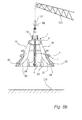
Fig. 5b is a schematic side view of the shell lifting tool in the active mode and when being used for lifting an outer crushing shell. -
Fig. 6 is a schematic side view of a shell lifting tool being used for lifting a large outer crushing shell. -
Fig. 1 illustrates a gyratory crushershell lifting tool 1 arranged inside a circular gyratory crusher outer crushingshell 2 for making it possible to lift the latter. InFig. 1 theshell 2 is shown in cross-section to better illustrate the details of theshell lifting tool 1. - The gyratory crusher
shell lifting tool 1 comprises a generally verticalcentral bar 4, alower hub 6 fixedly mounted at alower end 8 of thecentral bar 4, and anupper hub 9 arranged on the verticalcentral bar 4 above thelower hub 6 and comprising alocking mechanism 10. By means of thelocking mechanism 10 theupper hub 9 is releasably fixed to thecentral bar 4 and can be moved to various positions along thecentral bar 4, above thelower hub 6. - First, second, third and fourth lifting
legs upper hub 9. Thelegs devices upper hub 9, meaning that thelegs upper hub 9. The four liftinglegs central bar 4, meaning that when viewed from above, since there are four legs, thelegs - Each
leg portion 30 arranged at a respectivelower end 32, opposite to the respectiveupper end 20, of therespective leg respective lifting portion 30 is adapted to come into contact with aninner periphery 34 of the gyratory crusher outer crushingshell 2 when lifting the latter. - Each
leg central portion 36 thereof, journalled to arespective link central portion 36 to thelower hub 6. By "central portion 36" is meant a portion that is positioned within a central location CL of the full length FL of therespective lifting leg upper end 20 corresponding to about 5% of the full length FL of the liftingleg upper end 20 corresponding to about 75% of the full length FL of the liftingleg Fig. 1 thecentral portion 36 is located in the absolute middle of the lifting leg, i.e. exactly in the middle between theupper end 20 and thelower end 32, meaning a location of thecentral portion 36 corresponding to 50% of the full length FL of therespective lifting leg lower hub 6, therespective link devices lower hub 6. - The
respective link portion 30 of therespective leg central bar 4 when theupper hub 9 is moved downwards in the direction of thelower hub 6. Such movement downwards of theupper hub 9 is performed when thelifting tool 1 is adjusted to the crushingshell 2, by the liftingportions 30 being brought into contact with theinner periphery 34 of the outer crushingshell 2, just prior to lifting the crushingshell 2. - Similarly, the
respective link portion 30 of therespective leg central bar 4 when theupper hub 9 is moved vertically upwards and away from thelower hub 6. Such movement upwards of theupper hub 9 is performed when thelifting tool 1 is to be released from the outer crushingshell 2, by the liftingportions 30 being released from contact with theinner periphery 34 of the crushingshell 2, after having lifted the crushingshell 2. - The vertical
central bar 4 comprises, at anupper end 54 thereof, a lifting device, which in this embodiment has the form of a liftingeye 56. A crane or similar device can be connected to the liftingeye 56 to lift the gyratory crushershell lifting tool 1 and the gyratory crusher outer crushingshell 2. -
Fig. 2 illustrates the verticalcentral bar 4 and theupper hub 9 with itslocking mechanism 10 in more detail. Thelocking mechanism 10 is integrated into theupper hub 9 which provides for an efficient design with few parts. In the perspective illustrated inFig. 2 a cover plate and the bracket and bearingdevice 24 are not illustrated to show the relevant internal details of thelocking mechanism 10 more clearly. - The purpose of the
locking mechanism 10 is to enable adjustment of the vertical position of theupper hub 9 along the verticalcentral bar 4 and to thereby adjust the vertical turning position of thelegs - In the passive mode the
legs central bar 4, such that the gyratory crushershell lifting tool 1 can be inserted into, or removed from, the interior of the gyratory crusher outer crushingshell 2, as will be described hereinafter with reference toFig. 4 . In this passive mode, as will be described in more detail hereinafter, theupper hub 9 and thelocking mechanism 10 have been slid to an upper position along the verticalcentral bar 4. - In the active mode the
legs central bar 4, similar as is disclosed inFig. 1 , to make the respective outwardly directed liftingportion 30 at the respectivelower end 32 of therespective leg inner periphery 34 of the gyratory crusher outer crushingshell 2 such that the crushingshell 2 can be lifted. In this active mode, as will be described in more detail hereinafter with reference toFigs. 5a ,5b and6 , theupper hub 9 and thelocking mechanism 10 have been slid to a lower position along the verticalcentral bar 4, wherein the exact position along the verticalcentral bar 4 depends on the particular inner width of that crushingshell 2 that should be lifted. - The vertical
central bar 4 comprises a first and asecond row horizontal teeth 62 andhorizontal grooves 64 extending in opposite directions. Thelocking mechanism 10 comprises afirst locking member 66 and asecond locking member 68. Each lockingmember horizontal teeth 70 andhorizontal grooves 72 that are adapted to co-operate with thehorizontal teeth 62 andhorizontal grooves 64 of the verticalcentral bar 4 in a tooth-and-groove arrangement. - The
locking mechanism 10 comprises arelease mechanism 74, which inFig. 2 is shown in a locked state. Therelease mechanism 74 comprises a first and asecond slide plate slide plates control handle 80, also shown inFig. 1 . Eachslide plate pins 84 of the lockingmembers slide plates second slide plate pins 84 of the respective lockingmember members central bar 4, thereby disengaging theteeth 70 andgrooves 72 of the lockingmembers teeth 62 andgrooves 64 of the verticalcentral bar 4. - The
locking mechanism 10 is provided with a fail-safe device comprising, in this embodiment, two springs 85. Thesprings 85 are connected to therespective slide plates locking mechanism 10 from the locked state ofFig. 2 to a released state, described hereinafter with reference toFig. 3 , unless a securing mechanism of thelocking mechanism 10 has been properly installed to hold thelocking mechanism 10 in the locked state. InFig. 2 thesecuring mechanism 86 is schematically illustrated as two securingpins 86 that extend through therespective slide plates side wall 87 of thelocking mechanism 10 to secure theslide plates locking mechanism 10 to its locked state, the control handle 80 is pressed downwards, against the action of thesprings 85, until the securing pins 86 can be inserted, and in this locked state the lockingmembers central bar 4 as illustrated inFig. 2 . -
Fig. 3 illustrates the verticalcentral bar 4 and theupper hub 9, wherein therelease mechanism 74 of thelocking mechanism 10 is in the released state. This state has been reached by removing the securing pins 86, illustrated inFig. 2 , after which thesprings 85 have forced theslide plates members central bar 4. In this released state, when the lockingmembers central bar 4, thelocking mechanism 10, and thereby theupper hub 9 and the upper hub bracket and bearingdevices central bar 4 to set the desired inclination of thelegs -
Fig. 4 illustrates how the gyratory crushershell lifting tool 1 has been set to the passive mode, wherein thelegs central bar 4, by transferring thelocking mechanism 10 to its released state, illustrated inFig. 3 , and moving theupper hub 9 and thelocking mechanism 10 upwards to its upper position, adjacent to theupper end 54 of the verticalcentral bar 4, and then returning thelocking mechanism 10 to its locked state, illustrated inFig. 2 , and inserting the securing pins 86. Theupper hub 9 may be provided with a liftinghandle 88 to make it easier to move theupper hub 9 to its desired position. In this passive state the gyratory crushershell lifting tool 1 has been inserted into the interior of the gyratory crusher outer crushingshell 2, which lies on the ground GR. -
Fig. 5a illustrates, in a perspective which is turned 90° compared to the perspective ofFig. 4 , how the gyratory crushershell lifting tool 1 has been set to the active mode. The setting to the active mode has been made by transferring thelocking mechanism 10 to its released mode, illustrated inFig. 3 , moving theupper hub 9 with thelocking mechanism 10 vertically downwards along the verticalcentral bar 4, in a direction towards thelower hub 6, thereby making the liftinglegs upper hub 9, such that the respective lower ends 32 of thelegs portions 30 come into contact with theinner periphery 34 of the crushingshell 2, and then returning thelocking mechanism 10 to its locked state, illustrated inFig. 2 . In this active state the angle α between the vertical plane and therespective legs lifting tool 1 is, in this particular case, about 20°. -
Fig. 5b illustrates how a crane CR having a lifting hook LH has been connected to the liftingeye 56 of the gyratory crushershell lifting tool 1 and lifts the crushingshell 2 from the ground GR. - When the
shell lifting tool 1 and the crushingshell 2 have been lifted to the intended position for the crushingshell 2, for example another position on the ground GR, or to its intended position on a gyratory crusher, thelocking mechanism 10 is adjusted to its released state and thelifting tool 1 is set to the passive mode illustrated inFig. 4 , and theshell lifting tool 1 may then be removed from the interior of thecrusher shell 2. -
Fig. 6 illustrates how the gyratory crushershell lifting tool 1 is utilized for lifting a circular gyratory crusher outer crushingshell 102 that is considerably larger in inner diameter than the crushingshell 2 shown inFigs. 4, 5a and5b . Similar as with the above description, the gyratory crushershell lifting tool 1 has been set to the active mode, by transferring thelocking mechanism 10 to its released mode, moving theupper hub 9 and thelocking mechanism 10 vertically downwards along the verticalcentral bar 4, in the direction towards thelower hub 6, thereby making the respective lower ends 32 of thelegs portions 30 come into contact with theinner periphery 134 of the crushingshell 102, and then returning thelocking mechanism 10 to its locked state, whereby the crushingshell 102 can now be lifted from the ground. In this state the angle α between the vertical plane and therespective leg - Hence, one size of gyratory crusher
shell lifting tool 1 can be utilized for lifting gyratory crusher crushing shells having sizes that vary within wide ranges, from relatively small crushingshells 2, as shown inFigs. 4, 5a and5b , to relatively large crushingshells 102, as shown inFig. 6 . - It will be appreciated that numerous variants of the embodiments described above are possible within the scope of the appended claims.
- Hereinabove a
lifting tool 1 having four liftinglegs efficient lifting tool 1 with low cost and safe properties when it comes to lifting a crushingshell 2. - Hereinbefore it has been described that the gyratory crusher
shell lifting tool 1 comprises alower hub 6, which is fixed to alower end 8 of the verticalcentral bar 4, and anupper hub 9, which is arranged on the verticalcentral bar 4 above thelower hub 6 and which comprises alocking mechanism 10, making it possible to move theupper hub 9 to various positions along thecentral bar 4 to turn the liftinglegs shells 2. It will be appreciated that as alternative to thelower hub 6 being fixed to thecentral bar 4 and theupper hub 9 being releasably fixed to thecentral bar 4 by means of thelocking mechanism 10, it is also possible, according to an alternative embodiment, to arrange theupper hub 9 fixedly to thecentral bar 4, at an upper end thereof, and arrange thelower hub 6 releasably fixed to thecentral bar 4 by means of a locking mechanism, whereby thelower hub 6 can be moved along thecentral bar 4, below theupper hub 9, after the locking mechanism has been set to a released state. Furthermore, it is also possible to arrange both theupper hub 9 and thelower hub 6 with a respective locking mechanism, such that each of theupper hub 9 and thelower hub 6 can be moved along thecentral bar 4 when the respective locking mechanism has been set to the released state. - To summarize, a gyratory crusher shell lifting tool (1) adapted for lifting a gyratory crusher shell (2) comprises:
- a generally vertical central bar (4),
- a lower hub (6) arranged at a lower end (8) of the central bar (4),
- an upper hub (9) arranged at the central bar (4) above the lower hub (6),
- at least one locking mechanism (10) arranged on at least one of the upper and lower hubs (9, 6) to make that hub (9) releasably fixed to the central bar (4),
- a first lifting leg (12) and a second lifting leg (16) provided with a respective outwardly directed lifting portion (30) adapted to come into contact with an inner periphery (34) of the crushing shell (2), wherein the respective outwardly directed lifting portion (30) is moved away from the central bar (4) when one hub (9) is moved in the direction of the other hub (6).
Claims (15)
- A gyratory crusher shell lifting tool adapted for lifting a gyratory crusher shell (2), characterised in comprising:a generally vertical central bar (4),a lower hub (6) arranged at a lower end (8) of the central bar (4),an upper hub (9) arranged at the central bar (4) above the lower hub (6),at least one locking mechanism (10) arranged on at least one of the upper and lower hubs (9, 6) to make the at least one of the upper and lower hubs (9, 6) releasably fixed to the central bar (4),at least a first lifting leg (12) and a second lifting leg (16) that are provided with a respective outwardly directed lifting portion (30) adapted to come into contact with an inner periphery (34) of a gyratory crusher shell (2), wherein each of the first and second lifting legs (12, 16) are mounted to the upper hub (9) and being journalled therein to be turnable in a vertical direction relative to the upper hub (9), and wherein each lifting leg (12, 16) is journalled to a respective link (38, 42) extending to the lower hub (6), said respective link (38, 42) being adapted to move the respective outwardly directed lifting portion (30) of the respective leg (12, 16) away from the central bar (4) when at least one of the lower andupper hubs (6, 9) is moved in the direction of the other one of the lower and upper hubs (6, 9).
- A shell lifting tool according to claim 1, wherein the at least a first lifting leg (12) and a second lifting leg (16) are evenly distributed around the periphery of the central bar (4).
- A shell lifting tool according to any one of the preceding claims, wherein the shell lifting tool (1) comprises at least three lifting legs (12, 14, 16).
- A shell lifting tool according to any one of the preceding claims, wherein the shell lifting tool (1) comprises 3 - 8 lifting legs (12, 14, 16, 18), more preferably 4 - 5 lifting legs (12, 14, 16, 18).
- A shell lifting tool according to any one of the preceding claims, wherein the respective outwardly directed lifting portions (30) of the lifting legs (12, 16) are arranged at respective lower ends (32) of the respective legs (12, 16).
- A shell lifting tool according to any one of the preceding claims, wherein each lifting leg (12, 16) is journalled to the respective link (38, 42) extending to the lower hub (6) at a respective central portion (36) of the respective lifting leg (12, 16).
- A shell lifting tool according to any one of the preceding claims, wherein the upper hub (9) is provided with the locking mechanism (10) and is releasably fixed to the vertical central bar (4), and wherein the lower hub (6) is fixedly mounted to a lower end (8) of the vertical central bar (4).
- A shell lifting tool according to claim 7, wherein the locking mechanism (10) is integrated into the upper hub (9).
- A shell lifting tool according to any one of the preceding claims, wherein the locking mechanism (10) comprises at least one locking member (66, 68) which is adapted to co-operate with the vertical central bar (4) in a tooth-and-groove arrangement (62, 64, 70, 72) in a locked state of the locking mechanism (10).
- A shell lifting tool according to any one of the preceding claims, wherein a control handle (80) of the locking mechanism (10) is adapted for switching the position of at least one locking member (66, 68) between a locked state in which the locking member (66, 68) co-operates with the vertical central bar (4) and a released state in which the locking member (66, 68) and the vertical central bar (4) are released from each other.
- A shell lifting tool according to any one of the preceding claims, wherein the locking mechanism (10) is provided with a fail-safe device, such as a spring device (85), which is adapted to bring the locking mechanism (10) to a released state unless a securing mechanism (86) of the locking mechanism (10) has been properly installed to hold the locking mechanism (10) in a locked state.
- A shell lifting tool according to any one of the preceding claims, wherein the vertical central bar (4) is provided with a lifting device (56), such as a lifting eye, arranged in an upper end (54) thereof.
- A method of lifting a gyratory crusher shell, the method comprising:- placing a gyratory crusher shell lifting tool (1) inside the gyratory crusher shell (2), the shell lifting tool (1) comprising:a generally vertical central bar (4),a lower hub (6) arranged at a lower end (8) of the central bar (4),an upper hub (9) arranged at the central bar (4) above the lower hub (6),at least a first lifting leg (12) and a second lifting leg (16) that are provided with a respective outwardly directed lifting portion (30),wherein each of the first and second lifting legs (12, 16) are mounted to the upper hub (9) and being journalled therein to be turnable in a vertical direction relative to the upper hub (9), andwherein each lifting leg (12, 16) is journalled to a respective link (38, 42) extending to the lower hub (6), the method further comprising:- moving at least one of the lower and upper hubs (6, 9) in the direction of the other one of the lower and upper hubs (6, 9) to make the outwardly directed lifting portions (30) of the legs (12, 16) come into contact with an inner periphery (34) of the gyratory crusher shell (2),- locking at least that hub (6, 9) that has been moved to the vertical central bar (4), such that both hubs (6, 9) become fixed to the vertical central bar (4), and- lifting the shell lifting tool (1) and thereby lifting the gyratory crusher shell (2) together with it.
- A method according to claim 13, wherein said step of moving at least one of the lower and upper hubs (6, 9) in the direction of the other one of the lower and upper hubs (6, 9) includes moving the upper hub (9) downwardly in the direction of the lower hub (6), and wherein said step of locking at least that hub (6, 9) that has been moved to the vertical central bar (4) includes locking the upper hub (9) to the central bar (4).
- A method according to any one of claims 13-14, further comprising lifting the shell lifting tool (1) by connecting a lift (CR) to a lifting device (56) arranged at an upper end (54) of the vertical central bar (4).
Priority Applications (2)
| Application Number | Priority Date | Filing Date | Title |
|---|---|---|---|
| EP14160405.8A EP2921235B1 (en) | 2014-03-18 | 2014-03-18 | A gyratory crusher shell lifting tool |
| PCT/EP2015/053179 WO2015139897A1 (en) | 2014-03-18 | 2015-02-16 | A gyratory crusher shell lifting tool |
Applications Claiming Priority (1)
| Application Number | Priority Date | Filing Date | Title |
|---|---|---|---|
| EP14160405.8A EP2921235B1 (en) | 2014-03-18 | 2014-03-18 | A gyratory crusher shell lifting tool |
Publications (2)
| Publication Number | Publication Date |
|---|---|
| EP2921235A1 true EP2921235A1 (en) | 2015-09-23 |
| EP2921235B1 EP2921235B1 (en) | 2016-10-12 |
Family
ID=50289490
Family Applications (1)
| Application Number | Title | Priority Date | Filing Date |
|---|---|---|---|
| EP14160405.8A Not-in-force EP2921235B1 (en) | 2014-03-18 | 2014-03-18 | A gyratory crusher shell lifting tool |
Country Status (2)
| Country | Link |
|---|---|
| EP (1) | EP2921235B1 (en) |
| WO (1) | WO2015139897A1 (en) |
Cited By (1)
| Publication number | Priority date | Publication date | Assignee | Title |
|---|---|---|---|---|
| CN112638538A (en) * | 2018-08-30 | 2021-04-09 | 美卓奥图泰芬兰有限公司 | Crusher housing lifting device, apparatus and method |
Families Citing this family (3)
| Publication number | Priority date | Publication date | Assignee | Title |
|---|---|---|---|---|
| WO2022133516A1 (en) * | 2020-12-23 | 2022-06-30 | Makuri Technology Pty Ltd | A crusher mantle lifting device |
| US11911773B2 (en) | 2022-07-19 | 2024-02-27 | Kleemann Gmbh | Apparatus and method for attaching a crushing mantle of a cone crusher to a carrier cone of the cone crusher and for detaching the crushing mantle from the carrier cone |
| US11819857B1 (en) | 2022-07-19 | 2023-11-21 | Kleemann Gmbh | Apparatus and method for lifting a crushing mantle of a cone or gyratory crusher and crusher comprising such an apparatus for lifting |
Citations (4)
| Publication number | Priority date | Publication date | Assignee | Title |
|---|---|---|---|---|
| US2951725A (en) * | 1957-07-22 | 1960-09-06 | Worcester Automatic Machine Co | Material handling apparatus |
| GB886706A (en) * | 1960-09-06 | 1962-01-10 | Standard Telephones Cables Ltd | Improvements in or relating to apparatus for lifting and transporting drums or the like |
| US3088769A (en) * | 1961-10-18 | 1963-05-07 | Flex O Lators | Expansible lift for hollow objects |
| EP2692442A1 (en) * | 2012-08-02 | 2014-02-05 | Sandvik Intellectual Property AB | Gyratory crusher outer crushing shell |
-
2014
- 2014-03-18 EP EP14160405.8A patent/EP2921235B1/en not_active Not-in-force
-
2015
- 2015-02-16 WO PCT/EP2015/053179 patent/WO2015139897A1/en not_active Ceased
Patent Citations (5)
| Publication number | Priority date | Publication date | Assignee | Title |
|---|---|---|---|---|
| US2951725A (en) * | 1957-07-22 | 1960-09-06 | Worcester Automatic Machine Co | Material handling apparatus |
| GB886706A (en) * | 1960-09-06 | 1962-01-10 | Standard Telephones Cables Ltd | Improvements in or relating to apparatus for lifting and transporting drums or the like |
| US3088769A (en) * | 1961-10-18 | 1963-05-07 | Flex O Lators | Expansible lift for hollow objects |
| EP2692442A1 (en) * | 2012-08-02 | 2014-02-05 | Sandvik Intellectual Property AB | Gyratory crusher outer crushing shell |
| WO2014019762A1 (en) | 2012-08-02 | 2014-02-06 | Sandvik Intellectual Property Ab | Gyratory crusher outer crushing shell |
Cited By (3)
| Publication number | Priority date | Publication date | Assignee | Title |
|---|---|---|---|---|
| CN112638538A (en) * | 2018-08-30 | 2021-04-09 | 美卓奥图泰芬兰有限公司 | Crusher housing lifting device, apparatus and method |
| CN112638538B (en) * | 2018-08-30 | 2023-02-28 | 美卓奥图泰芬兰有限公司 | Crusher housing lifting device, apparatus and method |
| US11878308B2 (en) | 2018-08-30 | 2024-01-23 | Metso Outotec Finland Oy | Crusher mantle lifting device, an arrangement and a method |
Also Published As
| Publication number | Publication date |
|---|---|
| WO2015139897A1 (en) | 2015-09-24 |
| EP2921235B1 (en) | 2016-10-12 |
Similar Documents
| Publication | Publication Date | Title |
|---|---|---|
| EP2921235B1 (en) | A gyratory crusher shell lifting tool | |
| ES2396436T3 (en) | Arrangement for raising a tower wall part of a wind turbine and method for raising a tower wall part of a wind turbine | |
| BR112017010347B1 (en) | CARGO VESSEL LIFTING SYSTEM | |
| CN104261242A (en) | Lifting belt-type suspender for horizontal hoisting | |
| EP2864777B1 (en) | Method and system for conducting maintenance on a chromatography column | |
| JP5814661B2 (en) | Steel suspension equipment | |
| EP2692681B1 (en) | Hoisting device provided with a mechanical interlocking system | |
| CN102381623B (en) | Special lifting tool for circuit breaker | |
| JP2009511381A (en) | Lifting sling system | |
| CA2826124C (en) | System and method for lifting large off-highway truck-truck bodies | |
| JP2006219265A (en) | Self-aligning suspension and lifting method using the same | |
| KR20120088384A (en) | Turn over apparatus with double turning ring for turning over propeller of ship | |
| CN108190731B (en) | Lifting hook widening tool, lifting device and lifting equipment | |
| EP2799803B1 (en) | Lifting System for Low Profile Element Baskets for Rotary Regenerative Air Preheaters | |
| JP2013153955A (en) | Safety support for high place work | |
| CN215287652U (en) | Lifting appliance | |
| CN204686366U (en) | Spring compressor structure of the shock absorber | |
| KR20150027989A (en) | Assistant tool for crane | |
| CN207534112U (en) | A kind of column covering plate structure | |
| KR20230049399A (en) | Heavy object lifting device with semiautomatic locking and unlocking function | |
| CN207141223U (en) | It is a kind of to prevent that cage guide climbing robot from toppling the safety guard to fall | |
| JP2017019656A (en) | Fork type lifting device | |
| KR101533697B1 (en) | clamping device | |
| CN220449539U (en) | Hoisting device | |
| KR20120007300U (en) | Crane jig for trolly beam |
Legal Events
| Date | Code | Title | Description |
|---|---|---|---|
| PUAI | Public reference made under article 153(3) epc to a published international application that has entered the european phase |
Free format text: ORIGINAL CODE: 0009012 |
|
| 17P | Request for examination filed |
Effective date: 20140318 |
|
| AK | Designated contracting states |
Kind code of ref document: A1 Designated state(s): AL AT BE BG CH CY CZ DE DK EE ES FI FR GB GR HR HU IE IS IT LI LT LU LV MC MK MT NL NO PL PT RO RS SE SI SK SM TR |
|
| AX | Request for extension of the european patent |
Extension state: BA ME |
|
| RBV | Designated contracting states (corrected) |
Designated state(s): AL AT BE BG CH CY CZ DE DK EE ES FI FR GB GR HR HU IE IS IT LI LT LU LV MC MK MT NL NO PL PT RO RS SE SI SK SM TR |
|
| GRAP | Despatch of communication of intention to grant a patent |
Free format text: ORIGINAL CODE: EPIDOSNIGR1 |
|
| INTG | Intention to grant announced |
Effective date: 20160527 |
|
| GRAS | Grant fee paid |
Free format text: ORIGINAL CODE: EPIDOSNIGR3 |
|
| GRAA | (expected) grant |
Free format text: ORIGINAL CODE: 0009210 |
|
| AK | Designated contracting states |
Kind code of ref document: B1 Designated state(s): AL AT BE BG CH CY CZ DE DK EE ES FI FR GB GR HR HU IE IS IT LI LT LU LV MC MK MT NL NO PL PT RO RS SE SI SK SM TR |
|
| REG | Reference to a national code |
Ref country code: GB Ref legal event code: FG4D |
|
| REG | Reference to a national code |
Ref country code: CH Ref legal event code: EP |
|
| REG | Reference to a national code |
Ref country code: AT Ref legal event code: REF Ref document number: 835999 Country of ref document: AT Kind code of ref document: T Effective date: 20161015 |
|
| REG | Reference to a national code |
Ref country code: IE Ref legal event code: FG4D |
|
| REG | Reference to a national code |
Ref country code: DE Ref legal event code: R096 Ref document number: 602014004151 Country of ref document: DE |
|
| REG | Reference to a national code |
Ref country code: LT Ref legal event code: MG4D |
|
| REG | Reference to a national code |
Ref country code: NL Ref legal event code: MP Effective date: 20161012 |
|
| PG25 | Lapsed in a contracting state [announced via postgrant information from national office to epo] |
Ref country code: LV Free format text: LAPSE BECAUSE OF FAILURE TO SUBMIT A TRANSLATION OF THE DESCRIPTION OR TO PAY THE FEE WITHIN THE PRESCRIBED TIME-LIMIT Effective date: 20161012 |
|
| REG | Reference to a national code |
Ref country code: AT Ref legal event code: MK05 Ref document number: 835999 Country of ref document: AT Kind code of ref document: T Effective date: 20161012 |
|
| PG25 | Lapsed in a contracting state [announced via postgrant information from national office to epo] |
Ref country code: SE Free format text: LAPSE BECAUSE OF FAILURE TO SUBMIT A TRANSLATION OF THE DESCRIPTION OR TO PAY THE FEE WITHIN THE PRESCRIBED TIME-LIMIT Effective date: 20161012 Ref country code: NO Free format text: LAPSE BECAUSE OF FAILURE TO SUBMIT A TRANSLATION OF THE DESCRIPTION OR TO PAY THE FEE WITHIN THE PRESCRIBED TIME-LIMIT Effective date: 20170112 Ref country code: GR Free format text: LAPSE BECAUSE OF FAILURE TO SUBMIT A TRANSLATION OF THE DESCRIPTION OR TO PAY THE FEE WITHIN THE PRESCRIBED TIME-LIMIT Effective date: 20170113 Ref country code: LT Free format text: LAPSE BECAUSE OF FAILURE TO SUBMIT A TRANSLATION OF THE DESCRIPTION OR TO PAY THE FEE WITHIN THE PRESCRIBED TIME-LIMIT Effective date: 20161012 |
|
| PG25 | Lapsed in a contracting state [announced via postgrant information from national office to epo] |
Ref country code: RS Free format text: LAPSE BECAUSE OF FAILURE TO SUBMIT A TRANSLATION OF THE DESCRIPTION OR TO PAY THE FEE WITHIN THE PRESCRIBED TIME-LIMIT Effective date: 20161012 Ref country code: NL Free format text: LAPSE BECAUSE OF FAILURE TO SUBMIT A TRANSLATION OF THE DESCRIPTION OR TO PAY THE FEE WITHIN THE PRESCRIBED TIME-LIMIT Effective date: 20161012 Ref country code: AT Free format text: LAPSE BECAUSE OF FAILURE TO SUBMIT A TRANSLATION OF THE DESCRIPTION OR TO PAY THE FEE WITHIN THE PRESCRIBED TIME-LIMIT Effective date: 20161012 Ref country code: HR Free format text: LAPSE BECAUSE OF FAILURE TO SUBMIT A TRANSLATION OF THE DESCRIPTION OR TO PAY THE FEE WITHIN THE PRESCRIBED TIME-LIMIT Effective date: 20161012 Ref country code: PL Free format text: LAPSE BECAUSE OF FAILURE TO SUBMIT A TRANSLATION OF THE DESCRIPTION OR TO PAY THE FEE WITHIN THE PRESCRIBED TIME-LIMIT Effective date: 20161012 Ref country code: FI Free format text: LAPSE BECAUSE OF FAILURE TO SUBMIT A TRANSLATION OF THE DESCRIPTION OR TO PAY THE FEE WITHIN THE PRESCRIBED TIME-LIMIT Effective date: 20161012 Ref country code: ES Free format text: LAPSE BECAUSE OF FAILURE TO SUBMIT A TRANSLATION OF THE DESCRIPTION OR TO PAY THE FEE WITHIN THE PRESCRIBED TIME-LIMIT Effective date: 20161012 Ref country code: IS Free format text: LAPSE BECAUSE OF FAILURE TO SUBMIT A TRANSLATION OF THE DESCRIPTION OR TO PAY THE FEE WITHIN THE PRESCRIBED TIME-LIMIT Effective date: 20170212 Ref country code: BE Free format text: LAPSE BECAUSE OF FAILURE TO SUBMIT A TRANSLATION OF THE DESCRIPTION OR TO PAY THE FEE WITHIN THE PRESCRIBED TIME-LIMIT Effective date: 20161012 Ref country code: PT Free format text: LAPSE BECAUSE OF FAILURE TO SUBMIT A TRANSLATION OF THE DESCRIPTION OR TO PAY THE FEE WITHIN THE PRESCRIBED TIME-LIMIT Effective date: 20170213 |
|
| REG | Reference to a national code |
Ref country code: DE Ref legal event code: R097 Ref document number: 602014004151 Country of ref document: DE |
|
| PG25 | Lapsed in a contracting state [announced via postgrant information from national office to epo] |
Ref country code: DK Free format text: LAPSE BECAUSE OF FAILURE TO SUBMIT A TRANSLATION OF THE DESCRIPTION OR TO PAY THE FEE WITHIN THE PRESCRIBED TIME-LIMIT Effective date: 20161012 Ref country code: SK Free format text: LAPSE BECAUSE OF FAILURE TO SUBMIT A TRANSLATION OF THE DESCRIPTION OR TO PAY THE FEE WITHIN THE PRESCRIBED TIME-LIMIT Effective date: 20161012 Ref country code: EE Free format text: LAPSE BECAUSE OF FAILURE TO SUBMIT A TRANSLATION OF THE DESCRIPTION OR TO PAY THE FEE WITHIN THE PRESCRIBED TIME-LIMIT Effective date: 20161012 Ref country code: RO Free format text: LAPSE BECAUSE OF FAILURE TO SUBMIT A TRANSLATION OF THE DESCRIPTION OR TO PAY THE FEE WITHIN THE PRESCRIBED TIME-LIMIT Effective date: 20161012 Ref country code: CZ Free format text: LAPSE BECAUSE OF FAILURE TO SUBMIT A TRANSLATION OF THE DESCRIPTION OR TO PAY THE FEE WITHIN THE PRESCRIBED TIME-LIMIT Effective date: 20161012 |
|
| PLBE | No opposition filed within time limit |
Free format text: ORIGINAL CODE: 0009261 |
|
| STAA | Information on the status of an ep patent application or granted ep patent |
Free format text: STATUS: NO OPPOSITION FILED WITHIN TIME LIMIT |
|
| PG25 | Lapsed in a contracting state [announced via postgrant information from national office to epo] |
Ref country code: SM Free format text: LAPSE BECAUSE OF FAILURE TO SUBMIT A TRANSLATION OF THE DESCRIPTION OR TO PAY THE FEE WITHIN THE PRESCRIBED TIME-LIMIT Effective date: 20161012 Ref country code: IT Free format text: LAPSE BECAUSE OF FAILURE TO SUBMIT A TRANSLATION OF THE DESCRIPTION OR TO PAY THE FEE WITHIN THE PRESCRIBED TIME-LIMIT Effective date: 20161012 Ref country code: BG Free format text: LAPSE BECAUSE OF FAILURE TO SUBMIT A TRANSLATION OF THE DESCRIPTION OR TO PAY THE FEE WITHIN THE PRESCRIBED TIME-LIMIT Effective date: 20170112 |
|
| 26N | No opposition filed |
Effective date: 20170713 |
|
| REG | Reference to a national code |
Ref country code: DE Ref legal event code: R119 Ref document number: 602014004151 Country of ref document: DE |
|
| REG | Reference to a national code |
Ref country code: CH Ref legal event code: PL |
|
| PG25 | Lapsed in a contracting state [announced via postgrant information from national office to epo] |
Ref country code: MC Free format text: LAPSE BECAUSE OF FAILURE TO SUBMIT A TRANSLATION OF THE DESCRIPTION OR TO PAY THE FEE WITHIN THE PRESCRIBED TIME-LIMIT Effective date: 20161012 Ref country code: SI Free format text: LAPSE BECAUSE OF FAILURE TO SUBMIT A TRANSLATION OF THE DESCRIPTION OR TO PAY THE FEE WITHIN THE PRESCRIBED TIME-LIMIT Effective date: 20161012 |
|
| REG | Reference to a national code |
Ref country code: IE Ref legal event code: MM4A |
|
| REG | Reference to a national code |
Ref country code: FR Ref legal event code: ST Effective date: 20171130 |
|
| PG25 | Lapsed in a contracting state [announced via postgrant information from national office to epo] |
Ref country code: FR Free format text: LAPSE BECAUSE OF NON-PAYMENT OF DUE FEES Effective date: 20170331 Ref country code: LU Free format text: LAPSE BECAUSE OF NON-PAYMENT OF DUE FEES Effective date: 20170318 Ref country code: DE Free format text: LAPSE BECAUSE OF NON-PAYMENT OF DUE FEES Effective date: 20171003 |
|
| PG25 | Lapsed in a contracting state [announced via postgrant information from national office to epo] |
Ref country code: IE Free format text: LAPSE BECAUSE OF NON-PAYMENT OF DUE FEES Effective date: 20170318 Ref country code: LI Free format text: LAPSE BECAUSE OF NON-PAYMENT OF DUE FEES Effective date: 20170331 Ref country code: CH Free format text: LAPSE BECAUSE OF NON-PAYMENT OF DUE FEES Effective date: 20170331 |
|
| PG25 | Lapsed in a contracting state [announced via postgrant information from national office to epo] |
Ref country code: MT Free format text: LAPSE BECAUSE OF NON-PAYMENT OF DUE FEES Effective date: 20170318 |
|
| GBPC | Gb: european patent ceased through non-payment of renewal fee |
Effective date: 20180318 |
|
| PG25 | Lapsed in a contracting state [announced via postgrant information from national office to epo] |
Ref country code: GB Free format text: LAPSE BECAUSE OF NON-PAYMENT OF DUE FEES Effective date: 20180318 |
|
| PG25 | Lapsed in a contracting state [announced via postgrant information from national office to epo] |
Ref country code: HU Free format text: LAPSE BECAUSE OF FAILURE TO SUBMIT A TRANSLATION OF THE DESCRIPTION OR TO PAY THE FEE WITHIN THE PRESCRIBED TIME-LIMIT; INVALID AB INITIO Effective date: 20140318 |
|
| PG25 | Lapsed in a contracting state [announced via postgrant information from national office to epo] |
Ref country code: CY Free format text: LAPSE BECAUSE OF FAILURE TO SUBMIT A TRANSLATION OF THE DESCRIPTION OR TO PAY THE FEE WITHIN THE PRESCRIBED TIME-LIMIT Effective date: 20161012 |
|
| PG25 | Lapsed in a contracting state [announced via postgrant information from national office to epo] |
Ref country code: MK Free format text: LAPSE BECAUSE OF FAILURE TO SUBMIT A TRANSLATION OF THE DESCRIPTION OR TO PAY THE FEE WITHIN THE PRESCRIBED TIME-LIMIT Effective date: 20161012 |
|
| PG25 | Lapsed in a contracting state [announced via postgrant information from national office to epo] |
Ref country code: TR Free format text: LAPSE BECAUSE OF FAILURE TO SUBMIT A TRANSLATION OF THE DESCRIPTION OR TO PAY THE FEE WITHIN THE PRESCRIBED TIME-LIMIT Effective date: 20161012 |
|
| PG25 | Lapsed in a contracting state [announced via postgrant information from national office to epo] |
Ref country code: AL Free format text: LAPSE BECAUSE OF FAILURE TO SUBMIT A TRANSLATION OF THE DESCRIPTION OR TO PAY THE FEE WITHIN THE PRESCRIBED TIME-LIMIT Effective date: 20161012 |