EP2920521B1 - Indoor device for an air conditioner - Google Patents
Indoor device for an air conditioner Download PDFInfo
- Publication number
- EP2920521B1 EP2920521B1 EP13854416.8A EP13854416A EP2920521B1 EP 2920521 B1 EP2920521 B1 EP 2920521B1 EP 13854416 A EP13854416 A EP 13854416A EP 2920521 B1 EP2920521 B1 EP 2920521B1
- Authority
- EP
- European Patent Office
- Prior art keywords
- magnetic substance
- indoor device
- centrifugal fan
- panel
- air conditioner
- Prior art date
- Legal status (The legal status is an assumption and is not a legal conclusion. Google has not performed a legal analysis and makes no representation as to the accuracy of the status listed.)
- Active
Links
Images


Classifications
-
- F—MECHANICAL ENGINEERING; LIGHTING; HEATING; WEAPONS; BLASTING
- F24—HEATING; RANGES; VENTILATING
- F24F—AIR-CONDITIONING; AIR-HUMIDIFICATION; VENTILATION; USE OF AIR CURRENTS FOR SCREENING
- F24F1/00—Room units for air-conditioning, e.g. separate or self-contained units or units receiving primary air from a central station
-
- F—MECHANICAL ENGINEERING; LIGHTING; HEATING; WEAPONS; BLASTING
- F24—HEATING; RANGES; VENTILATING
- F24F—AIR-CONDITIONING; AIR-HUMIDIFICATION; VENTILATION; USE OF AIR CURRENTS FOR SCREENING
- F24F1/00—Room units for air-conditioning, e.g. separate or self-contained units or units receiving primary air from a central station
- F24F1/0007—Indoor units, e.g. fan coil units
- F24F1/0018—Indoor units, e.g. fan coil units characterised by fans
- F24F1/0022—Centrifugal or radial fans
-
- F—MECHANICAL ENGINEERING; LIGHTING; HEATING; WEAPONS; BLASTING
- F04—POSITIVE - DISPLACEMENT MACHINES FOR LIQUIDS; PUMPS FOR LIQUIDS OR ELASTIC FLUIDS
- F04D—NON-POSITIVE-DISPLACEMENT PUMPS
- F04D17/00—Radial-flow pumps, e.g. centrifugal pumps; Helico-centrifugal pumps
- F04D17/08—Centrifugal pumps
- F04D17/16—Centrifugal pumps for displacing without appreciable compression
-
- F—MECHANICAL ENGINEERING; LIGHTING; HEATING; WEAPONS; BLASTING
- F04—POSITIVE - DISPLACEMENT MACHINES FOR LIQUIDS; PUMPS FOR LIQUIDS OR ELASTIC FLUIDS
- F04D—NON-POSITIVE-DISPLACEMENT PUMPS
- F04D29/00—Details, component parts, or accessories
- F04D29/05—Shafts or bearings, or assemblies thereof, specially adapted for elastic fluid pumps
- F04D29/051—Axial thrust balancing
-
- F—MECHANICAL ENGINEERING; LIGHTING; HEATING; WEAPONS; BLASTING
- F04—POSITIVE - DISPLACEMENT MACHINES FOR LIQUIDS; PUMPS FOR LIQUIDS OR ELASTIC FLUIDS
- F04D—NON-POSITIVE-DISPLACEMENT PUMPS
- F04D29/00—Details, component parts, or accessories
- F04D29/05—Shafts or bearings, or assemblies thereof, specially adapted for elastic fluid pumps
- F04D29/056—Bearings
- F04D29/058—Bearings magnetic; electromagnetic
-
- F—MECHANICAL ENGINEERING; LIGHTING; HEATING; WEAPONS; BLASTING
- F04—POSITIVE - DISPLACEMENT MACHINES FOR LIQUIDS; PUMPS FOR LIQUIDS OR ELASTIC FLUIDS
- F04D—NON-POSITIVE-DISPLACEMENT PUMPS
- F04D29/00—Details, component parts, or accessories
- F04D29/26—Rotors specially for elastic fluids
- F04D29/28—Rotors specially for elastic fluids for centrifugal or helico-centrifugal pumps for radial-flow or helico-centrifugal pumps
- F04D29/281—Rotors specially for elastic fluids for centrifugal or helico-centrifugal pumps for radial-flow or helico-centrifugal pumps for fans or blowers
-
- F—MECHANICAL ENGINEERING; LIGHTING; HEATING; WEAPONS; BLASTING
- F04—POSITIVE - DISPLACEMENT MACHINES FOR LIQUIDS; PUMPS FOR LIQUIDS OR ELASTIC FLUIDS
- F04D—NON-POSITIVE-DISPLACEMENT PUMPS
- F04D29/00—Details, component parts, or accessories
- F04D29/40—Casings; Connections of working fluid
-
- F—MECHANICAL ENGINEERING; LIGHTING; HEATING; WEAPONS; BLASTING
- F04—POSITIVE - DISPLACEMENT MACHINES FOR LIQUIDS; PUMPS FOR LIQUIDS OR ELASTIC FLUIDS
- F04D—NON-POSITIVE-DISPLACEMENT PUMPS
- F04D29/00—Details, component parts, or accessories
- F04D29/66—Combating cavitation, whirls, noise, vibration or the like; Balancing
-
- F—MECHANICAL ENGINEERING; LIGHTING; HEATING; WEAPONS; BLASTING
- F04—POSITIVE - DISPLACEMENT MACHINES FOR LIQUIDS; PUMPS FOR LIQUIDS OR ELASTIC FLUIDS
- F04D—NON-POSITIVE-DISPLACEMENT PUMPS
- F04D29/00—Details, component parts, or accessories
- F04D29/66—Combating cavitation, whirls, noise, vibration or the like; Balancing
- F04D29/661—Combating cavitation, whirls, noise, vibration or the like; Balancing especially adapted for elastic fluid pumps
- F04D29/668—Combating cavitation, whirls, noise, vibration or the like; Balancing especially adapted for elastic fluid pumps damping or preventing mechanical vibrations
-
- F—MECHANICAL ENGINEERING; LIGHTING; HEATING; WEAPONS; BLASTING
- F24—HEATING; RANGES; VENTILATING
- F24F—AIR-CONDITIONING; AIR-HUMIDIFICATION; VENTILATION; USE OF AIR CURRENTS FOR SCREENING
- F24F13/00—Details common to, or for air-conditioning, air-humidification, ventilation or use of air currents for screening
- F24F13/20—Casings or covers
Definitions
- An indoor device for an air conditioner is disclosed herein.
- An air conditioner is a cooling and heating system that inhales indoor air, heat exchanges the air with heat with a refrigerant, and discharges the air to indoors. Further, an air conditioner is a device that forms a refrigerating cycle including a compressor-condenser-expander-evaporator arrangement.
- Air conditioners may be divided into separated type air conditioners, in which an outdoor unit or device and an indoor unit or device are separately and installed, and an integral type in which an outdoor unit or device and an indoor unit or device are integrally installed.
- separated type air conditioners in which an outdoor unit or device and an indoor unit or device are separately and installed
- integral type in which an outdoor unit or device and an indoor unit or device are integrally installed.
- multi-type air conditioners in which a plurality of indoor units or devices are connected to one outdoor unit or device and the plurality of indoor devices is installed in different spaces, are often employed.
- indoor devices may be mounted at or on a ceiling or a wall surface, and in order to reduce the occupying space of the indoor device, it may be advantageous to reduce a side surface thickness of the indoor device.
- due to vibration occurring in a rotating fan there is a limitation in reducing a gap between the fan and an orifice panel or between the fan and a case.
- the fan when mounting the indoor device at or on a wall surface, in a state in which the fan does not rotate, the fan does not remain vertical with respect to a bottom thereof, but rather, a tilt phenomenon in which the fan is inclined due to a weight of the fan itself occurs, and thus, when the fan starts to rotate, vibration greatly occurs, and when reducing a gap between the panel or the case and the fan is reduced, the fan may collide with the panel or the case.
- the documents JP 3 174362 U and JP H10 288196 A disclose centrifugal fans with magnets that limit rotor tilting.
- An objective of the present invention is to provide an indoor unit or device for an air conditioner that can reduce a thickness of a side surface.
- Another objective of the present invention is to provide an indoor unit or device for an air conditioner in which a fan is not inclined even in a state in which the fan does not rotate, which enables the fan to not collide with a panel or a case when the fan rotates.
- Another objective of the present invention is to provide an indoor unit or device for an air conditioner that may reduce generation of vibration or noise while a fan rotates.
- the invention provides an indoor device for an air conditioner according to claim 1.
- the first magnetic substance and the second magnetic substance may be formed with a ring-shaped magnet.
- the same pole may be formed in a concentric circle.
- the first magnetic substance and the second magnetic substance may be formed with a rubber magnet.
- a circumferential edge of an inner circumferential surface may be curved with a predetermined curvature so as to guide air inhaled by the centrifugal fan to form the orifice.
- the first magnetic substance may be formed at the outer circumference further than the orifice.
- the centrifugal fan may include a hub portion to couple to a rotation shaft of the motor, a blade portion in which one of the blades is fixed to the hub portion in a state in which a plurality of blades that extend in a direction receding from the rotation axis are arranged at a predetermined gap, and a circular rim formed at an outer circumference of the blade and fixed to the opposite side of the blade fixed to the hub portion.
- the second magnetic substance may be mounted in the circular rim.
- a third magnetic substance and a fourth magnetic substance that generate a repulsive force may be respectively installed at a third surface, which may be an opposite surface of a surface to which the blade is fixed in the hub portion and a fourth surface opposite to the third surface in the case.
- the third magnetic substance and the fourth magnetic substance may be a ring-shaped magnet in which the same pole is formed in a concentric circle and in which different poles are alternately formed in a radiation direction. Further, the third magnetic substance and the fourth magnetic substance may have a diameter smaller than that of the second magnetic substance.
- a ring-shaped fifth magnetic substance and sixth magnetic substance that generate a repulsive force may be respectively installed at the third surface.
- the fourth surface and the fifth magnetic substance and the sixth magnetic substance may have a diameter smaller than that of the third magnetic substance and the fourth magnetic substance.
- Embodiments disclosed herein provide an indoor unit or device of an air conditioner that may include a heat exchanger mounting panel in which an orifice for to pass air therethrough is formed, a centrifugal fan to inhale air in a shaft or axis direction through the orifice and discharge air in a radiation or radial direction, a motor to rotate the centrifugal fan, and a case to fix the motor and couple the motor to the panel.
- the centrifugal fan may include a hub portion to couple to a rotation shaft of the motor and a blade portion in which one side of the blade may be fixed to the hub portion in a state in which a plurality of blades that extends in a direction receding from the rotation axis are arranged at a predetermined gap.
- a first magnetic substance and a second magnetic substance that generate a repulsive force may be respectively installed at a first surface, which is an opposite surface of a surface to which the blade is fixed in the hub portion and a second surface opposite to the first surface in the case
- the first magnetic substance and the second magnetic substance may be a ring-shaped magnet in which the same pole is formed in a concentric circle and in which different poles are alternately formed in a radiation direction.
- the first magnetic substance and the second magnetic substance may be formed with a rubber magnet.
- a third magnetic substance and a fourth magnetic substance that generate a repulsive force may be respectively disposed at a third surface opposite to the centrifugal fan in the panel and a fourth surface opposite to the panel in the centrifugal fan.
- a circumferential edge of an inner circumferential surface thereof may be curved with a predetermined curvature so as to guide air inhaled by the centrifugal fan to form the orifice, and the centrifugal fan may further include a circular rim formed at an outer circumference side of the blade and fixed to the opposite side of the blade fixed to the hub portion.
- the third magnetic substance may be formed at the outer circumference further than the orifice, and the second magnetic substance may be mounted in the circular rim.
- the third magnetic substance and the fourth magnetic substance may be a ring-shaped magnet in which the same pole is formed in a concentric circle and in which different poles are alternately formed in a radiation direction.
- the third magnetic substance and the fourth magnetic substance may have a diameter larger than that of the first magnetic substance and the second magnetic substance.
- a tilt phenomenon in which a centrifugal fan is inclined in a stop state may be prevented, and a gap between a panel and a centrifugal fan may be reduced, and thus a side surface thickness of an indoor unit or device of an air conditioner may be efficiently reduced, and furthermore, while the centrifugal fan rotates, by suppressing vibration from occurring, noise may be reduced.
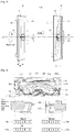
- FIG. 1 is an exploded view of an indoor device for an air conditioner
- FIG. 2 is a perspective view and a side view of the indoor device for an air conditioner of FIG. 1
- FIG. 3 illustrates an inclined centrifugal fan in a state in which the centrifugal fan of the indoor device for an air conditioner does not rotate.
- an indoor device 100 of the air conditioner may include a panel 10 to mount a heat exchanger, a centrifugal fan 11 having a plurality of blades, a motor 13 to rotate the centrifugal fan 11 at a high speed, and a holder 12 to securely fix the motor 13 to an inside of the case 14.
- the motor 13, the holder 12, the centrifugal fan 11, and the panel 10 may be sequentially fastened and assembled within a case 14.
- an end portion of a rotational axis of the motor 13 fastened to the hub may be a rotation center P 1 , but does not correspond to a gravitational center P 2 , of the centrifugal fan 11, and may be separated by a predetermined gap from the gravitational center P 2 . That is, due to separation between the rotational center P 1 of the motor 13 and the gravitational center P 2 of the centrifugal fan 11, when the centrifugal fan 11 rotates, vibration and noise may occur.
- a tilt phenomenon in which a plane B' perpendicular to a rotational shaft of the centrifugal fan 11 obliquely inclines clockwise, may occur, as shown in FIG. 3 , and thus, allowable space (e.g., d1 ? 10mm) within a predetermined gap, which should exist between a rear surface of the panel 10 and a front surface of the centrifugal fan 11, may be reduced.
- This may be an obstacle element in reducing a side surface thickness of the indoor device for an air conditioner.
- FIG. 4 is a cross-sectional view of an indoor device for an air conditioner according to embodiments.
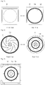
- FIG. 5 is a front view and a rear view of a magnetic substance installed at a rear surface of a heat exchanging panel of the indoor device for an air conditioner according to an embodiments.
- FIG. 6 is a front view and a rear view of a magnetic substance installed at a front surface and a rear surface of a centrifugal fan of the indoor device for an air conditioner according to embodiments.
- FIG. 7 illustrates a magnetic substance installed at an inside of a case of the indoor device for an air conditioner according to embodiments.
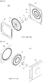
- FIGS. 8 and 9 are exploded views of the indoor device for an air conditioner according to embodiments.
- FIG. 10 is a side exploded view of the indoor device for an air conditioner according to embodiments.
- FIG. 11 illustrates the centrifugal fan, which is not inclined in a state in which the centrifugal fan of the indoor device for an air conditioner does not rotate according to an embodiments.
- the heat exchanger mounting panel 10, the centrifugal fan 11, the holder 12, the motor 13, and the case 14 may be assembled and fastened together.
- a first magnetic substance 10a may be installed, and at a front surface of the centrifugal fan 11, that is, at a surface facing an inhaling direction of air, a second magnetic substance 11a may be installed.
- the first magnetic substance 10a installed at the rear surface of the panel 10 and the second magnetic substance 11a installed at the front surface of the centrifugal fan 11 may face each other with the same polarity, that is, an N pole or an S pole, at an opposite separate position.
- the first magnetic substance 10a and the second magnetic substance 11a may generate a repulsive force.
- a heat exchanger holder 101 to mount a heat exchanger may be provided with, at a center thereof, an orifice 102 to pass inhaled air therethrough, and a bell mouse 103, a circumferential edge of an inner circumferential surface of which may be curved with a predetermined curvature so as to guide air inhaled by the centrifugal fan 11 to form the orifice 102.
- the centrifugal fan 11 inhales air in an axis or shaft direction through the orifice 102 and discharges the air in a radial direction and may include a hub portion 111 coupled to a rotational shaft of the motor 13 and that covers the motor 13, a blade portion 112, one side of a plurality of blades 112a of which may be fixed to the hub portion 111 in a state in which the plurality of blades 112a extends in a direction away from the rotational shaft arranged with a predetermined gap therebetween, and a circular rim 113 formed at an outer circumference of the plurality of blades 112a and fixed to a side of the hub portion 111 opposite to a side at which the plurality of blades 112a is fixed to the hub portion 111.
- the hub portion 111 may have a wide-brimmed hat shape, and an intermediate convex portion may be coupled to a rotational shaft of the motor 13, while covering the motor 13, and a brim portion may have the plurality of blades 112a of the blade portion 112 fixed thereto to guide air inhaled in the axis direction to flow in the radial direction.
- the circular rim 113 may be formed at an outside of the blade portion 112 to extend further than an outer diameter of the orifice 102 formed by the bell mouse 103 to pass air therethrough, and the second magnetic substance 11a may be mounted at a surface facing the panel 10 in the circular rim 113. Further, the first magnetic substance 10a may be mounted at a position corresponding to the second magnetic substance 11a at a surface facing the circular rim 113 in the panel 10, that is, a rear surface of the panel 10 to generate a repulsive force with the second magnetic substance 11a arranged with the same polarity and to maintain a constant gap from the second magnetic substance 11a.
- the first magnetic substance 10a and the second magnetic substance 11a may each be, for example, a ring-shaped magnet. Further, each may utilize a rubber magnet having flexibility.
- the first magnetic substance 10a may be installed adjacent an outer circumference of the orifice 102 formed at a center of the panel 10, as shown in FIG. 5 .
- As shown in FIG. 6 as the second magnetic substance 11a may be installed at an outer circumference of a front surface of the centrifugal fan 11, in a state in which the first magnetic substance 10a and the second magnetic substance 11a face each other, the first magnetic substance 10a and the second magnetic substance 11a may generate a repulsive force.
- the same pole may be formed in a concentric circle, and an N pole and an S pole, that is, different poles are alternately formed in a radial direction.
- an eccentric phenomenon in which the rotational shaft of the motor vibrates may be reduced.
- the third magnetic substance 11b and the fourth magnetic substance 14a may each be, for example, a ring-shaped magnet.
- the third magnetic substance 11b may be installed at a rear surface of the brim portion at an outer circumference of a rear surface of the centrifugal fan 11, and the fourth magnetic substance 14a may be installed at the inside of the case 14 opposite to the third magnetic substance 11b, and thus, the third magnetic substance 11b and the fourth magnetic substance 14a may generate a repulsive force in an opposite state or opposite direction.
- the fifth magnetic substance 11c may be, for example, a ring-shaped magnet having a diameter smaller than a diameter of the third magnetic substance 11b and may be installed at a rear surface of a portion corresponding to a brim portion of the hub portion 111.
- the sixth magnetic substance 14b may be, for example, a ring-shaped magnet having a diameter smaller than a diameter of the fourth magnetic substance 14a and may be installed at the inside of the case 14 opposite to the fifth magnetic substance 11c, and the sixth magnetic substance 14b may generate a repulsive force in a state facing the fifth magnetic substance 11c.
- the fifth magnetic substance 11c installed at a rear surface of the centrifugal fan 11 and the sixth magnetic substance 14b installed at the inside of the case 14 may not be emitted, to reduce costs of an air conditioner.
- the same pole may be formed in a concentric circle and different poles may be alternately formed in a radial direction, like the first magnetic substance 10a and the second magnetic substance 11a. Further, the third magnetic substance 11b and the sixth magnetic substance 14b may have a diameter smaller than a diameter of the first magnetic substance 10a and the second magnetic substance 11a.
- FIGS. 8 and 9 are exploded views of the indoor device for an air conditioner according to embodiments.
- the heat exchanger mounting panel 10 the centrifugal fan 11, the holder 12, the motor 13, and the case 14 may be sequentially fastened and assembled.
- the first magnetic substance 10a may be installed, and at the front surface of the centrifugal fan 11, the second magnetic substance 11a, which may be ring-shaped, may be installed.
- the third magnetic substance 11b and the fifth magnetic substance 11c which may be ring-shaped, may be installed, and at the inside of the case 14, the fourth magnetic substance 14a and the sixth magnetic substance 14b, which may be ring-shaped, may be installed.
- a repulsive force may occur between the first magnetic substance 10a and the second magnetic substance 11a
- a repulsive force may occur between the third magnetic substance 11b and the fourth magnetic substance 14a
- a repulsive force may occur between the fifth magnetic substance 11c and the sixth magnetic substance 14b.
- the first magnetic substance 10a may be installed at the rear surface of an outer circumferential portion corresponding to the brim portion and the second magnetic substance 11a may be installed at the inside of the case 14.
- the first magnetic substance 10a may be installed at the rear surface of the centrifugal fan 11 and the second magnetic substance 11a may be installed at the inside of the case 14. Further, the third magnetic substance 11b may be installed at the rear surface of the panel 10, the fourth magnetic substance 14a at the front surface of the centrifugal fan 11, the fifth magnetic substance 11c having a small diameter at the rear surface of the centrifugal fan 11, and a sixth magnetic substance 14b having a small diameter at the inside of the case 14 as a selective additional configuration.
Landscapes
- Engineering & Computer Science (AREA)
- Mechanical Engineering (AREA)
- General Engineering & Computer Science (AREA)
- Chemical & Material Sciences (AREA)
- Combustion & Propulsion (AREA)
- Physics & Mathematics (AREA)
- Electromagnetism (AREA)
- Structures Of Non-Positive Displacement Pumps (AREA)
- Air-Conditioning Room Units, And Self-Contained Units In General (AREA)
- Thermal Sciences (AREA)
Description
- An indoor device for an air conditioner is disclosed herein.
- Indoor devices for air conditioners are known. However, they suffer from various disadvantages.
- An air conditioner is a cooling and heating system that inhales indoor air, heat exchanges the air with heat with a refrigerant, and discharges the air to indoors. Further, an air conditioner is a device that forms a refrigerating cycle including a compressor-condenser-expander-evaporator arrangement.
- Air conditioners may be divided into separated type air conditioners, in which an outdoor unit or device and an indoor unit or device are separately and installed, and an integral type in which an outdoor unit or device and an indoor unit or device are integrally installed. Presently, multi-type air conditioners, in which a plurality of indoor units or devices are connected to one outdoor unit or device and the plurality of indoor devices is installed in different spaces, are often employed.
- In order to improve the appearance of air conditioners and to improve space efficiency, indoor devices may be mounted at or on a ceiling or a wall surface, and in order to reduce the occupying space of the indoor device, it may be advantageous to reduce a side surface thickness of the indoor device. However, due to vibration occurring in a rotating fan, there is a limitation in reducing a gap between the fan and an orifice panel or between the fan and a case. More particularly, when mounting the indoor device at or on a wall surface, in a state in which the fan does not rotate, the fan does not remain vertical with respect to a bottom thereof, but rather, a tilt phenomenon in which the fan is inclined due to a weight of the fan itself occurs, and thus, when the fan starts to rotate, vibration greatly occurs, and when reducing a gap between the panel or the case and the fan is reduced, the fan may collide with the panel or the case. The documents
JP 3 174362 U JP H10 288196 A - An objective of the present invention is to provide an indoor unit or device for an air conditioner that can reduce a thickness of a side surface.
- Another objective of the present invention is to provide an indoor unit or device for an air conditioner in which a fan is not inclined even in a state in which the fan does not rotate, which enables the fan to not collide with a panel or a case when the fan rotates.
- Another objective of the present invention is to provide an indoor unit or device for an air conditioner that may reduce generation of vibration or noise while a fan rotates.
- The invention provides an indoor device for an air conditioner according to claim 1. The first magnetic substance and the second magnetic substance may be formed with a ring-shaped magnet.
- In the first magnetic substance and the second magnetic substance, the same pole may be formed in a concentric circle. The first magnetic substance and the second magnetic substance may be formed with a rubber magnet.
- In the panel, a circumferential edge of an inner circumferential surface may be curved with a predetermined curvature so as to guide air inhaled by the centrifugal fan to form the orifice. The first magnetic substance may be formed at the outer circumference further than the orifice.
- The centrifugal fan may include a hub portion to couple to a rotation shaft of the motor, a blade portion in which one of the blades is fixed to the hub portion in a state in which a plurality of blades that extend in a direction receding from the rotation axis are arranged at a predetermined gap, and a circular rim formed at an outer circumference of the blade and fixed to the opposite side of the blade fixed to the hub portion. The second magnetic substance may be mounted in the circular rim.
- A third magnetic substance and a fourth magnetic substance that generate a repulsive force may be respectively installed at a third surface, which may be an opposite surface of a surface to which the blade is fixed in the hub portion and a fourth surface opposite to the third surface in the case. The third magnetic substance and the fourth magnetic substance may be a ring-shaped magnet in which the same pole is formed in a concentric circle and in which different poles are alternately formed in a radiation direction. Further, the third magnetic substance and the fourth magnetic substance may have a diameter smaller than that of the second magnetic substance.
- A ring-shaped fifth magnetic substance and sixth magnetic substance that generate a repulsive force may be respectively installed at the third surface. The fourth surface and the fifth magnetic substance and the sixth magnetic substance may have a diameter smaller than that of the third magnetic substance and the fourth magnetic substance.
- Embodiments disclosed herein provide an indoor unit or device of an air conditioner that may include a heat exchanger mounting panel in which an orifice for to pass air therethrough is formed, a centrifugal fan to inhale air in a shaft or axis direction through the orifice and discharge air in a radiation or radial direction, a motor to rotate the centrifugal fan, and a case to fix the motor and couple the motor to the panel. The centrifugal fan may include a hub portion to couple to a rotation shaft of the motor and a blade portion in which one side of the blade may be fixed to the hub portion in a state in which a plurality of blades that extends in a direction receding from the rotation axis are arranged at a predetermined gap. A first magnetic substance and a second magnetic substance that generate a repulsive force may be respectively installed at a first surface, which is an opposite surface of a surface to which the blade is fixed in the hub portion and a second surface opposite to the first surface in the case.
- The first magnetic substance and the second magnetic substance may be a ring-shaped magnet in which the same pole is formed in a concentric circle and in which different poles are alternately formed in a radiation direction. The first magnetic substance and the second magnetic substance may be formed with a rubber magnet. A third magnetic substance and a fourth magnetic substance that generate a repulsive force may be respectively disposed at a third surface opposite to the centrifugal fan in the panel and a fourth surface opposite to the panel in the centrifugal fan.
- In the panel, a circumferential edge of an inner circumferential surface thereof may be curved with a predetermined curvature so as to guide air inhaled by the centrifugal fan to form the orifice, and the centrifugal fan may further include a circular rim formed at an outer circumference side of the blade and fixed to the opposite side of the blade fixed to the hub portion. The third magnetic substance may be formed at the outer circumference further than the orifice, and the second magnetic substance may be mounted in the circular rim.
- The third magnetic substance and the fourth magnetic substance may be a ring-shaped magnet in which the same pole is formed in a concentric circle and in which different poles are alternately formed in a radiation direction. The third magnetic substance and the fourth magnetic substance may have a diameter larger than that of the first magnetic substance and the second magnetic substance.
- Accordingly, a tilt phenomenon in which a centrifugal fan is inclined in a stop state may be prevented, and a gap between a panel and a centrifugal fan may be reduced, and thus a side surface thickness of an indoor unit or device of an air conditioner may be efficiently reduced, and furthermore, while the centrifugal fan rotates, by suppressing vibration from occurring, noise may be reduced.
- Embodiments will be described in detail with reference to the following drawings in which like reference numerals refer to like elements, and wherein:
-
FIG. 1 is an exploded view of an indoor device for an air conditioner; -
FIG. 2 is a perspective view and a side view of the indoor device for an air conditioner ofFIG. 1 ; -
FIG. 3 illustrates an inclined centrifugal fan in a state in which the centrifugal fan of the indoor device for an air conditioner does not rotate; -
FIG. 4 is a cross-sectional view of an indoor device for an air conditioner according to an embodiment of the invention; -
FIG. 5 is a front view and a rear view of a magnetic substance installed at a rear surface of a heat exchanging panel of the indoor device for an air conditioner according to embodiments; -
FIG. 6 is a front view and a rear view of a magnetic substance installed at a front surface and a rear surface of a centrifugal fan of the indoor device for an air conditioner according to embodiments; -
FIG. 7 illustrates a magnetic substance installed at an inside of a case of the indoor device for an air conditioner according to embodiments; -
FIGS. 8 and 9 are exploded views of the indoor device for an air conditioner according to embodiments; -
FIG. 10 is a side exploded view of the indoor device for an air conditioner according to embodiments; and -
FIG. 11 illustrates the centrifugal fan, which is not inclined in a state in which the centrifugal fan of the indoor device for an air conditioner does not rotate according to embodiments. - Hereinafter, an indoor device for an air conditioner according to embodiments will be described in detail with reference to the accompanying drawings. Where possible, like reference numerals have been used to indicate like elements, and repetitive disclosure has been omitted.
-
FIG. 1 is an exploded view of an indoor device for an air conditioner, andFIG. 2 is a perspective view and a side view of the indoor device for an air conditioner ofFIG. 1 .FIG. 3 illustrates an inclined centrifugal fan in a state in which the centrifugal fan of the indoor device for an air conditioner does not rotate. As shown inFIG. 1 , anindoor device 100 of the air conditioner may include apanel 10 to mount a heat exchanger, acentrifugal fan 11 having a plurality of blades, amotor 13 to rotate thecentrifugal fan 11 at a high speed, and aholder 12 to securely fix themotor 13 to an inside of thecase 14. As shown inFIG. 2 , in theindoor device 100 of the air conditioner, themotor 13, theholder 12, thecentrifugal fan 11, and thepanel 10 may be sequentially fastened and assembled within acase 14. - However, as shown in
FIG. 3 , when themotor 13 is fastened in an inserted state within a hub depressed at a center of thecentrifugal fan 11, an end portion of a rotational axis of themotor 13 fastened to the hub may be a rotation center P1, but does not correspond to a gravitational center P2, of thecentrifugal fan 11, and may be separated by a predetermined gap from the gravitational center P2. That is, due to separation between the rotational center P1 of themotor 13 and the gravitational center P2 of thecentrifugal fan 11, when thecentrifugal fan 11 rotates, vibration and noise may occur. - Further, when a rotation operation of the
centrifugal fan 11 is stopped, a tilt phenomenon in which a plane B' perpendicular to a rotational shaft of thecentrifugal fan 11 obliquely inclines clockwise, may occur, as shown inFIG. 3 , and thus, allowable space (e.g., d1 ? 10mm) within a predetermined gap, which should exist between a rear surface of thepanel 10 and a front surface of thecentrifugal fan 11, may be reduced. This may be an obstacle element in reducing a side surface thickness of the indoor device for an air conditioner. -
FIG. 4 is a cross-sectional view of an indoor device for an air conditioner according to embodiments.FIG. 5 is a front view and a rear view of a magnetic substance installed at a rear surface of a heat exchanging panel of the indoor device for an air conditioner according to an embodiments.FIG. 6 is a front view and a rear view of a magnetic substance installed at a front surface and a rear surface of a centrifugal fan of the indoor device for an air conditioner according to embodiments.FIG. 7 illustrates a magnetic substance installed at an inside of a case of the indoor device for an air conditioner according to embodiments.FIGS. 8 and 9 are exploded views of the indoor device for an air conditioner according to embodiments.FIG. 10 is a side exploded view of the indoor device for an air conditioner according to embodiments.FIG. 11 illustrates the centrifugal fan, which is not inclined in a state in which the centrifugal fan of the indoor device for an air conditioner does not rotate according to an embodiments. - In the
indoor device 100a for an air conditioner according to embodiments disclosed herein, as described above with reference toFIGS. 1 to 3 , the heatexchanger mounting panel 10, thecentrifugal fan 11, theholder 12, themotor 13, and thecase 14 may be assembled and fastened together. In one embodiment, at a rear surface of the heatexchanger mounting panel 10, a firstmagnetic substance 10a may be installed, and at a front surface of thecentrifugal fan 11, that is, at a surface facing an inhaling direction of air, a secondmagnetic substance 11a may be installed. By providing the firstmagnetic substance 10a installed at the rear surface of thepanel 10 and the secondmagnetic substance 11a installed at the front surface of thecentrifugal fan 11 to face each other with the same polarity, that is, an N pole or an S pole, at an opposite separate position, the firstmagnetic substance 10a and the secondmagnetic substance 11a may generate a repulsive force. - As shown in
FIG. 4 , in thepanel 10, aheat exchanger holder 101 to mount a heat exchanger may be provided with, at a center thereof, anorifice 102 to pass inhaled air therethrough, and abell mouse 103, a circumferential edge of an inner circumferential surface of which may be curved with a predetermined curvature so as to guide air inhaled by thecentrifugal fan 11 to form theorifice 102. - The
centrifugal fan 11 inhales air in an axis or shaft direction through theorifice 102 and discharges the air in a radial direction and may include ahub portion 111 coupled to a rotational shaft of themotor 13 and that covers themotor 13, ablade portion 112, one side of a plurality ofblades 112a of which may be fixed to thehub portion 111 in a state in which the plurality ofblades 112a extends in a direction away from the rotational shaft arranged with a predetermined gap therebetween, and acircular rim 113 formed at an outer circumference of the plurality ofblades 112a and fixed to a side of thehub portion 111 opposite to a side at which the plurality ofblades 112a is fixed to thehub portion 111. - The
hub portion 111 may have a wide-brimmed hat shape, and an intermediate convex portion may be coupled to a rotational shaft of themotor 13, while covering themotor 13, and a brim portion may have the plurality ofblades 112a of theblade portion 112 fixed thereto to guide air inhaled in the axis direction to flow in the radial direction. - The
circular rim 113 may be formed at an outside of theblade portion 112 to extend further than an outer diameter of theorifice 102 formed by thebell mouse 103 to pass air therethrough, and the secondmagnetic substance 11a may be mounted at a surface facing thepanel 10 in thecircular rim 113. Further, the firstmagnetic substance 10a may be mounted at a position corresponding to the secondmagnetic substance 11a at a surface facing thecircular rim 113 in thepanel 10, that is, a rear surface of thepanel 10 to generate a repulsive force with the secondmagnetic substance 11a arranged with the same polarity and to maintain a constant gap from the secondmagnetic substance 11a. - The first
magnetic substance 10a and the secondmagnetic substance 11a may each be, for example, a ring-shaped magnet. Further, each may utilize a rubber magnet having flexibility. The firstmagnetic substance 10a may be installed adjacent an outer circumference of theorifice 102 formed at a center of thepanel 10, as shown inFIG. 5 . As shown inFIG. 6 , as the secondmagnetic substance 11a may be installed at an outer circumference of a front surface of thecentrifugal fan 11, in a state in which the firstmagnetic substance 10a and the secondmagnetic substance 11a face each other, the firstmagnetic substance 10a and the secondmagnetic substance 11a may generate a repulsive force. - As shown in
FIG. 4 , in the firstmagnetic substance 10a and the secondmagnetic substance 11a, the same pole may be formed in a concentric circle, and an N pole and an S pole, that is, different poles are alternately formed in a radial direction. Thus, when thecentrifugal fan 11 rotates, an eccentric phenomenon in which the rotational shaft of the motor vibrates may be reduced. - At a rear surface of the
centrifugal fan 11, that is, at a rear surface of thehub portion 111, which is a surface opposite to a surface to which the plurality ofblades 112a is fixed to thehub portion 111, as shown inFIG. 6 , at least one of a thirdmagnetic substance 11b and a fifthmagnetic substance 11c may be installed, and as shown inFIG. 7 , at an inside of thecase 14, that is, at a surface opposite to a rear surface of thehub portion 111, at least one of a fourthmagnetic substance 14a and a sixthmagnetic substance 14b may be installed. - The third
magnetic substance 11b and the fourthmagnetic substance 14a may each be, for example, a ring-shaped magnet. The thirdmagnetic substance 11b may be installed at a rear surface of the brim portion at an outer circumference of a rear surface of thecentrifugal fan 11, and the fourthmagnetic substance 14a may be installed at the inside of thecase 14 opposite to the thirdmagnetic substance 11b, and thus, the thirdmagnetic substance 11b and the fourthmagnetic substance 14a may generate a repulsive force in an opposite state or opposite direction. - As shown in
FIG. 6 , the fifthmagnetic substance 11c may be, for example, a ring-shaped magnet having a diameter smaller than a diameter of the thirdmagnetic substance 11b and may be installed at a rear surface of a portion corresponding to a brim portion of thehub portion 111. Further, as shown inFIG. 7 , the sixthmagnetic substance 14b may be, for example, a ring-shaped magnet having a diameter smaller than a diameter of the fourthmagnetic substance 14a and may be installed at the inside of thecase 14 opposite to the fifthmagnetic substance 11c, and the sixthmagnetic substance 14b may generate a repulsive force in a state facing the fifthmagnetic substance 11c. - Alternatively, the fifth
magnetic substance 11c installed at a rear surface of thecentrifugal fan 11 and the sixthmagnetic substance 14b installed at the inside of thecase 14 may not be emitted, to reduce costs of an air conditioner. - In the third
magnetic substance 11b and the sixthmagnetic substance 14b, the same pole may be formed in a concentric circle and different poles may be alternately formed in a radial direction, like the firstmagnetic substance 10a and the secondmagnetic substance 11a. Further, the thirdmagnetic substance 11b and the sixthmagnetic substance 14b may have a diameter smaller than a diameter of the firstmagnetic substance 10a and the secondmagnetic substance 11a. -
FIGS. 8 and 9 are exploded views of the indoor device for an air conditioner according to embodiments. In the indoor device 110a for the air conditioner according to embodiments, the heatexchanger mounting panel 10, thecentrifugal fan 11, theholder 12, themotor 13, and thecase 14 may be sequentially fastened and assembled. At the rear surface of thepanel 10, the firstmagnetic substance 10a may be installed, and at the front surface of thecentrifugal fan 11, the secondmagnetic substance 11a, which may be ring-shaped, may be installed. Further, at the rear surface of thecentrifugal fan 11, the thirdmagnetic substance 11b and the fifthmagnetic substance 11c, which may be ring-shaped, may be installed, and at the inside of thecase 14, the fourthmagnetic substance 14a and the sixthmagnetic substance 14b, which may be ring-shaped, may be installed. - That is, a repulsive force may occur between the first
magnetic substance 10a and the secondmagnetic substance 11a, a repulsive force may occur between the thirdmagnetic substance 11b and the fourthmagnetic substance 14a, and a repulsive force may occur between the fifthmagnetic substance 11c and the sixthmagnetic substance 14b. Accordingly, as shown inFIG. 11 , even if allowable space d2 (d2<d1) is reduced between the rear surface of thepanel 10 and the front surface of thecentrifugal fan 11, the slimtype air conditioner 100a may constantly maintain a gap between the rear surface of thepanel 10 and the front surface of thecentrifugal fan 11 by a repulsive force generated by the magnetic substances. Therefore, by suppressing vibration by generating the repulsive force by the corresponding magnetic substance pairs while the centrifugal fan rotates, noise may be reduced. - Further, as shown in
FIG. 11 , even if a rotational operation of thecentrifugal fan 11 is stopped, a tilt phenomenon in which a plane B perpendicular to the rotational shaft of thecentrifugal fan 11 is inclined clockwise may be prevented, by efficiently reducing allowable space (for example, d2 4mm) between the rear surface of thepanel 10 and the front surface of thecentrifugal fan 11, and a side surface thickness of the indoor device for an air conditioner may be reduced. - According to another embodiment, at the outer circumference of the rear surface of the
centrifugal fan 11, that is, in thehub portion 111, the firstmagnetic substance 10a may be installed at the rear surface of an outer circumferential portion corresponding to the brim portion and the secondmagnetic substance 11a may be installed at the inside of thecase 14. By installing the firstmagnetic substance 10a and the secondmagnetic substance 11a to be opposite to each other, while the centrifugal fan rotates, vibration may be suppressed or prevented from occurring, and thus, noise may be reduced. Further, even if the rotational operation of the centrifugal fan is stopped, a tilt phenomenon may be prevented, and thus, a side surface thickness of the indoor device for an air conditioner may be efficiently reduced. - That is, with this embodiment, the first
magnetic substance 10a may be installed at the rear surface of thecentrifugal fan 11 and the secondmagnetic substance 11a may be installed at the inside of thecase 14. Further, the thirdmagnetic substance 11b may be installed at the rear surface of thepanel 10, the fourthmagnetic substance 14a at the front surface of thecentrifugal fan 11, the fifthmagnetic substance 11c having a small diameter at the rear surface of thecentrifugal fan 11, and a sixthmagnetic substance 14b having a small diameter at the inside of thecase 14 as a selective additional configuration. - The exemplary embodiments should be considered in descriptive sense only and not for purposes of limitation. Therefore, the scope of the invention is defined not by the detailed description but by the appended claims.
Claims (13)
- An indoor device for an air conditioner, comprising:a heat exchanger mounting panel (10) in which an orifice (102) to pass air therethrough is formed;a centrifugal fan (11) to inhale air in a shaft direction through the orifice and discharge the air in a radial direction;a motor (13) to rotate the centrifugal fan (11); anda case (14) to fix the motor (13) and couple the motor (13) to the panel (10),characterized in thata first magnetic substance (10a) and a second magnetic substance (11a) that generate a repulsive force are respectively disposed at a first surface opposite to the centrifugal fan (11) in the panel (10) and a second surface opposite to the panel (10) in the centrifugal fan (11),and in that in the first magnetic substance (10a) and the second magnetic substance (11a), different poles are alternately formed in a radial direction.
- The indoor device of claim 1, wherein the first magnetic substance (10a) and the second magnetic substance (11a) each comprises a ring-shaped magnet.
- The indoor device of claim 1 or claim 2, wherein in the first magnetic substance (10a) and the second magnetic substance (11a), the same pole is formed in a concentric circle.
- The indoor device of one of preceding claims, wherein the first magnetic substance (10a) and the second magnetic substance (11a) each comprises a rubber magnet.
- The indoor device of one of preceding claims, wherein a circumferential edge of an inner circumferential surface of the panel (10) is curved with a predetermined curvature to form the orifice (102) so as to guide air inhaled by the centrifugal fan (11), and wherein the first magnetic substance (10a) is disposed adjacent an outer circumference of the circumferential edge of the inner circumferential surface of the panel (10).
- The indoor device of one of preceding claims, wherein the centrifugal fan (11) comprises:a hub portion (111) to couple to a rotational shaft of the motor (13);a blade portion (112), a first side of a plurality of blades of which is fixed to the hub portion (111) in a state in which the plurality of blades extends in a direction away from a rotational axis with a predetermined gap formed therebetween; anda circular rim (113) formed at an outer circumference of the plurality of blades and fixed to a second side of the plurality of blades opposite to the first side fixed to the hub portion (111), wherein the second magnetic substance (11a) is disposed at the circular rim (113).
- The indoor device of claim 6, wherein a third magnetic substance (11b) and a fourth magnetic substance (14a) that generate a repulsive force are respectively disposed at a third surface, which is a surface opposite to a surface to which the plurality of blades is fixed in the hub portion (111), and a fourth surface opposite to the third surface in the case (14), respectively.
- The indoor device of claim 7, wherein the third magnetic substance (11b) and the fourth magnetic substance (14a) each comprises a ring-shaped magnet in which the same pole is formed in a concentric circle.
- The indoor device of claim 8, wherein different poles are alternately formed in a radial direction in the ring-shaped magnet.
- The indoor device of one of claims 7 to 9, wherein the third magnetic substance (11b) and the fourth magnetic substance (14a) each have a diameter smaller than a diameter of the second magnetic substance (11a).
- The indoor device of one of claims 7 to 10, wherein a fifth magnetic substance (11c) and a sixth magnetic substance (14b) that generate a repulsive force are respectively disposed at the third surface and the fourth surface.
- The indoor device of claim 11, wherein the fifth magnetic substance (11c) and the sixth magnetic substance (14b) each comprises a ring-shaped magnet and have a diameter smaller than a diameter of the third magnetic substance (11b) and the fourth magnetic substance (14a).
- An air conditioner comprising the indoor device of one of claims 1 to 12.
Applications Claiming Priority (2)
| Application Number | Priority Date | Filing Date | Title |
|---|---|---|---|
| KR1020120129192A KR20140065026A (en) | 2012-11-15 | 2012-11-15 | Slim type air conditioner |
| PCT/KR2013/010314 WO2014077592A1 (en) | 2012-11-15 | 2013-11-14 | Indoor device for an air conditioner |
Publications (3)
| Publication Number | Publication Date |
|---|---|
| EP2920521A1 EP2920521A1 (en) | 2015-09-23 |
| EP2920521A4 EP2920521A4 (en) | 2016-07-27 |
| EP2920521B1 true EP2920521B1 (en) | 2019-10-09 |
Family
ID=50680550
Family Applications (1)
| Application Number | Title | Priority Date | Filing Date |
|---|---|---|---|
| EP13854416.8A Active EP2920521B1 (en) | 2012-11-15 | 2013-11-14 | Indoor device for an air conditioner |
Country Status (5)
| Country | Link |
|---|---|
| US (1) | US9435547B2 (en) |
| EP (1) | EP2920521B1 (en) |
| KR (1) | KR20140065026A (en) |
| CN (1) | CN104797886B (en) |
| WO (1) | WO2014077592A1 (en) |
Families Citing this family (4)
| Publication number | Priority date | Publication date | Assignee | Title |
|---|---|---|---|---|
| CN104807096A (en) * | 2015-05-08 | 2015-07-29 | 珠海格力电器股份有限公司 | Indoor machine of air conditioner |
| CN105546661B (en) * | 2016-02-19 | 2018-11-06 | 珠海格力电器股份有限公司 | Air conditioner |
| WO2021221391A1 (en) | 2020-04-27 | 2021-11-04 | Samsung Electronics Co., Ltd. | Motor assembly and a cleaner comprising the same |
| CZ2021539A3 (en) * | 2021-11-26 | 2023-07-19 | ALTEKO, s.r.o. | Air transport and treatment equipment |
Citations (1)
| Publication number | Priority date | Publication date | Assignee | Title |
|---|---|---|---|---|
| JPH10288196A (en) * | 1997-04-16 | 1998-10-27 | Daikin Ind Ltd | Turbo fan device |
Family Cites Families (9)
| Publication number | Priority date | Publication date | Assignee | Title |
|---|---|---|---|---|
| KR0123022B1 (en) * | 1995-03-20 | 1997-12-01 | 구자홍 | Combining structure of airconditioner |
| KR20060093985A (en) * | 2005-02-23 | 2006-08-28 | 엘지전자 주식회사 | Air conditioner |
| KR101181545B1 (en) * | 2005-10-26 | 2012-09-10 | 엘지전자 주식회사 | Indoor unit of air conditioner |
| TWI293106B (en) | 2005-11-22 | 2008-02-01 | Sunonwealth Electr Mach Ind Co | Thin-type fan |
| US20100242518A1 (en) | 2006-02-07 | 2010-09-30 | Lg Electronics Inc. | Indoor Unit of Air Conditioner |
| KR101474425B1 (en) * | 2008-01-21 | 2014-12-22 | 엘지전자 주식회사 | Fan assembly for refrigerator |
| US20110280753A1 (en) * | 2010-05-12 | 2011-11-17 | Chien-Chang Chen | Tilt-preventing fan |
| TWM423280U (en) * | 2011-05-26 | 2012-02-21 | Delta Electronics Inc | Fan |
| KR101918225B1 (en) * | 2012-02-15 | 2018-11-13 | 엘지전자 주식회사 | Indoor unit |
-
2012
- 2012-11-15 KR KR1020120129192A patent/KR20140065026A/en not_active Ceased
-
2013
- 2013-11-14 US US14/079,783 patent/US9435547B2/en active Active
- 2013-11-14 CN CN201380059242.1A patent/CN104797886B/en active Active
- 2013-11-14 WO PCT/KR2013/010314 patent/WO2014077592A1/en not_active Ceased
- 2013-11-14 EP EP13854416.8A patent/EP2920521B1/en active Active
Patent Citations (1)
| Publication number | Priority date | Publication date | Assignee | Title |
|---|---|---|---|---|
| JPH10288196A (en) * | 1997-04-16 | 1998-10-27 | Daikin Ind Ltd | Turbo fan device |
Also Published As
| Publication number | Publication date |
|---|---|
| US20140131018A1 (en) | 2014-05-15 |
| CN104797886B (en) | 2017-07-25 |
| EP2920521A1 (en) | 2015-09-23 |
| CN104797886A (en) | 2015-07-22 |
| KR20140065026A (en) | 2014-05-29 |
| WO2014077592A1 (en) | 2014-05-22 |
| EP2920521A4 (en) | 2016-07-27 |
| US9435547B2 (en) | 2016-09-06 |
Similar Documents
| Publication | Publication Date | Title |
|---|---|---|
| JP6401727B2 (en) | Outdoor unit for blower and air conditioner | |
| JPWO2015190077A1 (en) | Temperature conditioning unit, temperature conditioning system, and vehicle equipped with temperature conditioning unit | |
| US9664407B2 (en) | Indoor unit for air-conditioning apparatus with fan bellmouth and motor stay | |
| JP2015516045A (en) | Fan | |
| US9435547B2 (en) | Indoor device for an air conditioner | |
| JP6620427B2 (en) | Blower | |
| EP2937570A1 (en) | Centrifugal fan | |
| EP4400777A1 (en) | Ceiling-embedded air conditioner | |
| EP2792886B1 (en) | Turbofan | |
| CN101617174A (en) | The outdoor unit of the air conditioner and the blower of the outdoor unit | |
| JP4874360B2 (en) | Impeller, multi-blade fan and air conditioner | |
| JP6200679B2 (en) | Microparticle diffusion device and illumination device | |
| TW200530539A (en) | Integral air conditioner | |
| WO2017086125A1 (en) | Fan unit and outdoor unit | |
| JP2002349476A (en) | Series fan | |
| JPWO2017042865A1 (en) | Air conditioner outdoor unit | |
| JP2001295788A (en) | Fan motor integrated blower | |
| EP1726890B1 (en) | Indoor unit of an air conditioner | |
| WO2017086124A1 (en) | Fan unit and outdoor unit | |
| JP2019011870A (en) | Fan unit and outdoor equipment | |
| CN101675303B (en) | Air conditioner | |
| JP2019011873A (en) | Fan unit and outdoor equipment | |
| JP5106181B2 (en) | Ventilation fan | |
| CN222773445U (en) | Air outlet grille and air conditioner outdoor unit | |
| KR20180128286A (en) | Wireless charging electric fan |
Legal Events
| Date | Code | Title | Description |
|---|---|---|---|
| PUAI | Public reference made under article 153(3) epc to a published international application that has entered the european phase |
Free format text: ORIGINAL CODE: 0009012 |
|
| 17P | Request for examination filed |
Effective date: 20150615 |
|
| AK | Designated contracting states |
Kind code of ref document: A1 Designated state(s): AL AT BE BG CH CY CZ DE DK EE ES FI FR GB GR HR HU IE IS IT LI LT LU LV MC MK MT NL NO PL PT RO RS SE SI SK SM TR |
|
| AX | Request for extension of the european patent |
Extension state: BA ME |
|
| DAX | Request for extension of the european patent (deleted) | ||
| RA4 | Supplementary search report drawn up and despatched (corrected) |
Effective date: 20160627 |
|
| RIC1 | Information provided on ipc code assigned before grant |
Ipc: F04D 29/40 20060101ALI20160621BHEP Ipc: F24F 1/00 20110101AFI20160621BHEP Ipc: F24F 13/20 20060101ALI20160621BHEP Ipc: F04D 29/66 20060101ALI20160621BHEP |
|
| GRAP | Despatch of communication of intention to grant a patent |
Free format text: ORIGINAL CODE: EPIDOSNIGR1 |
|
| STAA | Information on the status of an ep patent application or granted ep patent |
Free format text: STATUS: GRANT OF PATENT IS INTENDED |
|
| INTG | Intention to grant announced |
Effective date: 20190408 |
|
| GRAS | Grant fee paid |
Free format text: ORIGINAL CODE: EPIDOSNIGR3 |
|
| GRAJ | Information related to disapproval of communication of intention to grant by the applicant or resumption of examination proceedings by the epo deleted |
Free format text: ORIGINAL CODE: EPIDOSDIGR1 |
|
| GRAL | Information related to payment of fee for publishing/printing deleted |
Free format text: ORIGINAL CODE: EPIDOSDIGR3 |
|
| STAA | Information on the status of an ep patent application or granted ep patent |
Free format text: STATUS: REQUEST FOR EXAMINATION WAS MADE |
|
| GRAR | Information related to intention to grant a patent recorded |
Free format text: ORIGINAL CODE: EPIDOSNIGR71 |
|
| STAA | Information on the status of an ep patent application or granted ep patent |
Free format text: STATUS: GRANT OF PATENT IS INTENDED |
|
| GRAA | (expected) grant |
Free format text: ORIGINAL CODE: 0009210 |
|
| STAA | Information on the status of an ep patent application or granted ep patent |
Free format text: STATUS: THE PATENT HAS BEEN GRANTED |
|
| INTG | Intention to grant announced |
Effective date: 20190828 |
|
| AK | Designated contracting states |
Kind code of ref document: B1 Designated state(s): AL AT BE BG CH CY CZ DE DK EE ES FI FR GB GR HR HU IE IS IT LI LT LU LV MC MK MT NL NO PL PT RO RS SE SI SK SM TR |
|
| REG | Reference to a national code |
Ref country code: GB Ref legal event code: FG4D |
|
| REG | Reference to a national code |
Ref country code: CH Ref legal event code: EP |
|
| REG | Reference to a national code |
Ref country code: DE Ref legal event code: R096 Ref document number: 602013061616 Country of ref document: DE |
|
| REG | Reference to a national code |
Ref country code: IE Ref legal event code: FG4D |
|
| REG | Reference to a national code |
Ref country code: AT Ref legal event code: REF Ref document number: 1189296 Country of ref document: AT Kind code of ref document: T Effective date: 20191115 |
|
| REG | Reference to a national code |
Ref country code: NL Ref legal event code: MP Effective date: 20191009 |
|
| REG | Reference to a national code |
Ref country code: LT Ref legal event code: MG4D |
|
| REG | Reference to a national code |
Ref country code: AT Ref legal event code: MK05 Ref document number: 1189296 Country of ref document: AT Kind code of ref document: T Effective date: 20191009 |
|
| PG25 | Lapsed in a contracting state [announced via postgrant information from national office to epo] |
Ref country code: PT Free format text: LAPSE BECAUSE OF FAILURE TO SUBMIT A TRANSLATION OF THE DESCRIPTION OR TO PAY THE FEE WITHIN THE PRESCRIBED TIME-LIMIT Effective date: 20200210 Ref country code: LV Free format text: LAPSE BECAUSE OF FAILURE TO SUBMIT A TRANSLATION OF THE DESCRIPTION OR TO PAY THE FEE WITHIN THE PRESCRIBED TIME-LIMIT Effective date: 20191009 Ref country code: AT Free format text: LAPSE BECAUSE OF FAILURE TO SUBMIT A TRANSLATION OF THE DESCRIPTION OR TO PAY THE FEE WITHIN THE PRESCRIBED TIME-LIMIT Effective date: 20191009 Ref country code: SE Free format text: LAPSE BECAUSE OF FAILURE TO SUBMIT A TRANSLATION OF THE DESCRIPTION OR TO PAY THE FEE WITHIN THE PRESCRIBED TIME-LIMIT Effective date: 20191009 Ref country code: GR Free format text: LAPSE BECAUSE OF FAILURE TO SUBMIT A TRANSLATION OF THE DESCRIPTION OR TO PAY THE FEE WITHIN THE PRESCRIBED TIME-LIMIT Effective date: 20200110 Ref country code: FI Free format text: LAPSE BECAUSE OF FAILURE TO SUBMIT A TRANSLATION OF THE DESCRIPTION OR TO PAY THE FEE WITHIN THE PRESCRIBED TIME-LIMIT Effective date: 20191009 Ref country code: BG Free format text: LAPSE BECAUSE OF FAILURE TO SUBMIT A TRANSLATION OF THE DESCRIPTION OR TO PAY THE FEE WITHIN THE PRESCRIBED TIME-LIMIT Effective date: 20200109 Ref country code: NO Free format text: LAPSE BECAUSE OF FAILURE TO SUBMIT A TRANSLATION OF THE DESCRIPTION OR TO PAY THE FEE WITHIN THE PRESCRIBED TIME-LIMIT Effective date: 20200109 Ref country code: NL Free format text: LAPSE BECAUSE OF FAILURE TO SUBMIT A TRANSLATION OF THE DESCRIPTION OR TO PAY THE FEE WITHIN THE PRESCRIBED TIME-LIMIT Effective date: 20191009 Ref country code: PL Free format text: LAPSE BECAUSE OF FAILURE TO SUBMIT A TRANSLATION OF THE DESCRIPTION OR TO PAY THE FEE WITHIN THE PRESCRIBED TIME-LIMIT Effective date: 20191009 Ref country code: LT Free format text: LAPSE BECAUSE OF FAILURE TO SUBMIT A TRANSLATION OF THE DESCRIPTION OR TO PAY THE FEE WITHIN THE PRESCRIBED TIME-LIMIT Effective date: 20191009 Ref country code: ES Free format text: LAPSE BECAUSE OF FAILURE TO SUBMIT A TRANSLATION OF THE DESCRIPTION OR TO PAY THE FEE WITHIN THE PRESCRIBED TIME-LIMIT Effective date: 20191009 |
|
| PG25 | Lapsed in a contracting state [announced via postgrant information from national office to epo] |
Ref country code: HR Free format text: LAPSE BECAUSE OF FAILURE TO SUBMIT A TRANSLATION OF THE DESCRIPTION OR TO PAY THE FEE WITHIN THE PRESCRIBED TIME-LIMIT Effective date: 20191009 Ref country code: IS Free format text: LAPSE BECAUSE OF FAILURE TO SUBMIT A TRANSLATION OF THE DESCRIPTION OR TO PAY THE FEE WITHIN THE PRESCRIBED TIME-LIMIT Effective date: 20200224 Ref country code: RS Free format text: LAPSE BECAUSE OF FAILURE TO SUBMIT A TRANSLATION OF THE DESCRIPTION OR TO PAY THE FEE WITHIN THE PRESCRIBED TIME-LIMIT Effective date: 20191009 |
|
| PG25 | Lapsed in a contracting state [announced via postgrant information from national office to epo] |
Ref country code: AL Free format text: LAPSE BECAUSE OF FAILURE TO SUBMIT A TRANSLATION OF THE DESCRIPTION OR TO PAY THE FEE WITHIN THE PRESCRIBED TIME-LIMIT Effective date: 20191009 |
|
| REG | Reference to a national code |
Ref country code: CH Ref legal event code: PL |
|
| REG | Reference to a national code |
Ref country code: DE Ref legal event code: R097 Ref document number: 602013061616 Country of ref document: DE |
|
| PG2D | Information on lapse in contracting state deleted |
Ref country code: IS |
|
| PG25 | Lapsed in a contracting state [announced via postgrant information from national office to epo] |
Ref country code: EE Free format text: LAPSE BECAUSE OF FAILURE TO SUBMIT A TRANSLATION OF THE DESCRIPTION OR TO PAY THE FEE WITHIN THE PRESCRIBED TIME-LIMIT Effective date: 20191009 Ref country code: LI Free format text: LAPSE BECAUSE OF NON-PAYMENT OF DUE FEES Effective date: 20191130 Ref country code: LU Free format text: LAPSE BECAUSE OF NON-PAYMENT OF DUE FEES Effective date: 20191114 Ref country code: RO Free format text: LAPSE BECAUSE OF FAILURE TO SUBMIT A TRANSLATION OF THE DESCRIPTION OR TO PAY THE FEE WITHIN THE PRESCRIBED TIME-LIMIT Effective date: 20191009 Ref country code: CZ Free format text: LAPSE BECAUSE OF FAILURE TO SUBMIT A TRANSLATION OF THE DESCRIPTION OR TO PAY THE FEE WITHIN THE PRESCRIBED TIME-LIMIT Effective date: 20191009 Ref country code: MC Free format text: LAPSE BECAUSE OF FAILURE TO SUBMIT A TRANSLATION OF THE DESCRIPTION OR TO PAY THE FEE WITHIN THE PRESCRIBED TIME-LIMIT Effective date: 20191009 Ref country code: DK Free format text: LAPSE BECAUSE OF FAILURE TO SUBMIT A TRANSLATION OF THE DESCRIPTION OR TO PAY THE FEE WITHIN THE PRESCRIBED TIME-LIMIT Effective date: 20191009 Ref country code: CH Free format text: LAPSE BECAUSE OF NON-PAYMENT OF DUE FEES Effective date: 20191130 Ref country code: IS Free format text: LAPSE BECAUSE OF FAILURE TO SUBMIT A TRANSLATION OF THE DESCRIPTION OR TO PAY THE FEE WITHIN THE PRESCRIBED TIME-LIMIT Effective date: 20200209 |
|
| PLBE | No opposition filed within time limit |
Free format text: ORIGINAL CODE: 0009261 |
|
| STAA | Information on the status of an ep patent application or granted ep patent |
Free format text: STATUS: NO OPPOSITION FILED WITHIN TIME LIMIT |
|
| REG | Reference to a national code |
Ref country code: BE Ref legal event code: MM Effective date: 20191130 |
|
| PG25 | Lapsed in a contracting state [announced via postgrant information from national office to epo] |
Ref country code: IT Free format text: LAPSE BECAUSE OF FAILURE TO SUBMIT A TRANSLATION OF THE DESCRIPTION OR TO PAY THE FEE WITHIN THE PRESCRIBED TIME-LIMIT Effective date: 20191009 Ref country code: SM Free format text: LAPSE BECAUSE OF FAILURE TO SUBMIT A TRANSLATION OF THE DESCRIPTION OR TO PAY THE FEE WITHIN THE PRESCRIBED TIME-LIMIT Effective date: 20191009 Ref country code: SK Free format text: LAPSE BECAUSE OF FAILURE TO SUBMIT A TRANSLATION OF THE DESCRIPTION OR TO PAY THE FEE WITHIN THE PRESCRIBED TIME-LIMIT Effective date: 20191009 |
|
| 26N | No opposition filed |
Effective date: 20200710 |
|
| GBPC | Gb: european patent ceased through non-payment of renewal fee |
Effective date: 20200109 |
|
| PG25 | Lapsed in a contracting state [announced via postgrant information from national office to epo] |
Ref country code: IE Free format text: LAPSE BECAUSE OF NON-PAYMENT OF DUE FEES Effective date: 20191114 Ref country code: GB Free format text: LAPSE BECAUSE OF NON-PAYMENT OF DUE FEES Effective date: 20200109 Ref country code: FR Free format text: LAPSE BECAUSE OF NON-PAYMENT OF DUE FEES Effective date: 20191209 |
|
| PG25 | Lapsed in a contracting state [announced via postgrant information from national office to epo] |
Ref country code: SI Free format text: LAPSE BECAUSE OF FAILURE TO SUBMIT A TRANSLATION OF THE DESCRIPTION OR TO PAY THE FEE WITHIN THE PRESCRIBED TIME-LIMIT Effective date: 20191009 Ref country code: BE Free format text: LAPSE BECAUSE OF NON-PAYMENT OF DUE FEES Effective date: 20191130 |
|
| PG25 | Lapsed in a contracting state [announced via postgrant information from national office to epo] |
Ref country code: CY Free format text: LAPSE BECAUSE OF FAILURE TO SUBMIT A TRANSLATION OF THE DESCRIPTION OR TO PAY THE FEE WITHIN THE PRESCRIBED TIME-LIMIT Effective date: 20191009 |
|
| PG25 | Lapsed in a contracting state [announced via postgrant information from national office to epo] |
Ref country code: HU Free format text: LAPSE BECAUSE OF FAILURE TO SUBMIT A TRANSLATION OF THE DESCRIPTION OR TO PAY THE FEE WITHIN THE PRESCRIBED TIME-LIMIT; INVALID AB INITIO Effective date: 20131114 Ref country code: MT Free format text: LAPSE BECAUSE OF FAILURE TO SUBMIT A TRANSLATION OF THE DESCRIPTION OR TO PAY THE FEE WITHIN THE PRESCRIBED TIME-LIMIT Effective date: 20191009 |
|
| PG25 | Lapsed in a contracting state [announced via postgrant information from national office to epo] |
Ref country code: TR Free format text: LAPSE BECAUSE OF FAILURE TO SUBMIT A TRANSLATION OF THE DESCRIPTION OR TO PAY THE FEE WITHIN THE PRESCRIBED TIME-LIMIT Effective date: 20191009 |
|
| PG25 | Lapsed in a contracting state [announced via postgrant information from national office to epo] |
Ref country code: MK Free format text: LAPSE BECAUSE OF FAILURE TO SUBMIT A TRANSLATION OF THE DESCRIPTION OR TO PAY THE FEE WITHIN THE PRESCRIBED TIME-LIMIT Effective date: 20191009 |
|
| PGFP | Annual fee paid to national office [announced via postgrant information from national office to epo] |
Ref country code: DE Payment date: 20251002 Year of fee payment: 13 |