KR20140065026A - Slim type air conditioner - Google Patents
Slim type air conditioner Download PDFInfo
- Publication number
- KR20140065026A KR20140065026A KR1020120129192A KR20120129192A KR20140065026A KR 20140065026 A KR20140065026 A KR 20140065026A KR 1020120129192 A KR1020120129192 A KR 1020120129192A KR 20120129192 A KR20120129192 A KR 20120129192A KR 20140065026 A KR20140065026 A KR 20140065026A
- Authority
- KR
- South Korea
- Prior art keywords
- magnetic body
- centrifugal fan
- air conditioner
- rear surface
- case
- Prior art date
Links
Images


Classifications
-
- F—MECHANICAL ENGINEERING; LIGHTING; HEATING; WEAPONS; BLASTING
- F24—HEATING; RANGES; VENTILATING
- F24F—AIR-CONDITIONING; AIR-HUMIDIFICATION; VENTILATION; USE OF AIR CURRENTS FOR SCREENING
- F24F1/00—Room units for air-conditioning, e.g. separate or self-contained units or units receiving primary air from a central station
-
- F—MECHANICAL ENGINEERING; LIGHTING; HEATING; WEAPONS; BLASTING
- F04—POSITIVE - DISPLACEMENT MACHINES FOR LIQUIDS; PUMPS FOR LIQUIDS OR ELASTIC FLUIDS
- F04D—NON-POSITIVE-DISPLACEMENT PUMPS
- F04D17/00—Radial-flow pumps, e.g. centrifugal pumps; Helico-centrifugal pumps
- F04D17/08—Centrifugal pumps
- F04D17/16—Centrifugal pumps for displacing without appreciable compression
-
- F—MECHANICAL ENGINEERING; LIGHTING; HEATING; WEAPONS; BLASTING
- F04—POSITIVE - DISPLACEMENT MACHINES FOR LIQUIDS; PUMPS FOR LIQUIDS OR ELASTIC FLUIDS
- F04D—NON-POSITIVE-DISPLACEMENT PUMPS
- F04D29/00—Details, component parts, or accessories
- F04D29/05—Shafts or bearings, or assemblies thereof, specially adapted for elastic fluid pumps
- F04D29/051—Axial thrust balancing
-
- F—MECHANICAL ENGINEERING; LIGHTING; HEATING; WEAPONS; BLASTING
- F04—POSITIVE - DISPLACEMENT MACHINES FOR LIQUIDS; PUMPS FOR LIQUIDS OR ELASTIC FLUIDS
- F04D—NON-POSITIVE-DISPLACEMENT PUMPS
- F04D29/00—Details, component parts, or accessories
- F04D29/05—Shafts or bearings, or assemblies thereof, specially adapted for elastic fluid pumps
- F04D29/056—Bearings
- F04D29/058—Bearings magnetic; electromagnetic
-
- F—MECHANICAL ENGINEERING; LIGHTING; HEATING; WEAPONS; BLASTING
- F04—POSITIVE - DISPLACEMENT MACHINES FOR LIQUIDS; PUMPS FOR LIQUIDS OR ELASTIC FLUIDS
- F04D—NON-POSITIVE-DISPLACEMENT PUMPS
- F04D29/00—Details, component parts, or accessories
- F04D29/26—Rotors specially for elastic fluids
- F04D29/28—Rotors specially for elastic fluids for centrifugal or helico-centrifugal pumps for radial-flow or helico-centrifugal pumps
- F04D29/281—Rotors specially for elastic fluids for centrifugal or helico-centrifugal pumps for radial-flow or helico-centrifugal pumps for fans or blowers
-
- F—MECHANICAL ENGINEERING; LIGHTING; HEATING; WEAPONS; BLASTING
- F04—POSITIVE - DISPLACEMENT MACHINES FOR LIQUIDS; PUMPS FOR LIQUIDS OR ELASTIC FLUIDS
- F04D—NON-POSITIVE-DISPLACEMENT PUMPS
- F04D29/00—Details, component parts, or accessories
- F04D29/40—Casings; Connections of working fluid
-
- F—MECHANICAL ENGINEERING; LIGHTING; HEATING; WEAPONS; BLASTING
- F04—POSITIVE - DISPLACEMENT MACHINES FOR LIQUIDS; PUMPS FOR LIQUIDS OR ELASTIC FLUIDS
- F04D—NON-POSITIVE-DISPLACEMENT PUMPS
- F04D29/00—Details, component parts, or accessories
- F04D29/66—Combating cavitation, whirls, noise, vibration or the like; Balancing
- F04D29/661—Combating cavitation, whirls, noise, vibration or the like; Balancing especially adapted for elastic fluid pumps
- F04D29/668—Combating cavitation, whirls, noise, vibration or the like; Balancing especially adapted for elastic fluid pumps damping or preventing mechanical vibrations
-
- F—MECHANICAL ENGINEERING; LIGHTING; HEATING; WEAPONS; BLASTING
- F24—HEATING; RANGES; VENTILATING
- F24F—AIR-CONDITIONING; AIR-HUMIDIFICATION; VENTILATION; USE OF AIR CURRENTS FOR SCREENING
- F24F1/00—Room units for air-conditioning, e.g. separate or self-contained units or units receiving primary air from a central station
- F24F1/0007—Indoor units, e.g. fan coil units
- F24F1/0018—Indoor units, e.g. fan coil units characterised by fans
- F24F1/0022—Centrifugal or radial fans
-
- F—MECHANICAL ENGINEERING; LIGHTING; HEATING; WEAPONS; BLASTING
- F24—HEATING; RANGES; VENTILATING
- F24F—AIR-CONDITIONING; AIR-HUMIDIFICATION; VENTILATION; USE OF AIR CURRENTS FOR SCREENING
- F24F13/00—Details common to, or for air-conditioning, air-humidification, ventilation or use of air currents for screening
- F24F13/20—Casings or covers
Abstract
Description
본 발명은, 예를 들어, 에어컨 실내기 등에 적합하도록 측면 두께가 얇게 슬림화된 슬림형 공기 조화기에 관한 것이다.
The present invention relates to a slim type air conditioner, for example, which is thinner and thinner in lateral thickness so as to be suitable for an air conditioner indoor unit or the like.
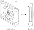
도 1은, 일반적인 공기 조화기의 분해 조립도를 도시한 것이고, 도 2는, 일반적인 공기 조화기의 사시도와 측면도를 도시한 것이다.Fig. 1 shows a disassembly assembly diagram of a general air conditioner, and Fig. 2 shows a perspective view and a side view of a general air conditioner.
예를 들어, 에어컨 실내기 등에 적용되는 공기 조화기(100)에는, 도 1에 도시한 바와 같이, 열교환기를 장착하기 위한 패널(10)과, 다수의 블레이드(Blade)가 형성된 원심 팬(11)이 포함 구성될 수 있다. 1, a
또한, 상기 공기 조화기(100)에는, 상기 원심 팬(11)을 고속으로 회전시키기 위한 모터(13)와, 상기 모터(13)를 케이스(14)의 내측에 견고하게 고정시키기 위한 홀더(12) 등이 포함 구성될 수 있다. The
그리고, 상기 공기 조화기(100)는, 예를 들어, 도 2에 도시한 바와 같이, 상기 케이스(14) 내에, 패널(10), 원심 팬(11), 홀더(12), 그리고 모터(13) 등을 순차적으로 조립 체결하여 제작하게 된다. 2, the
한편, 상기와 같이 조립 체결되는 공기 조화기(100)를, 에어컨 실내기 등에 적용하기 위해서는, 측면(Side)의 두께가 가능한 얇게 슬림(Slim)화된 슬림형 공기 조화기로 제작되는 것이 바람직하다. Meanwhile, in order to apply the
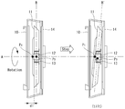
그러나, 도 3에 도시한 바와 같이, 상기 원심 팬(11)의 중앙에 함몰되어 있는 허브(Hub) 내에, 상기 모터(13)가 삽입된 상태로 체결되면, 상기 모터(13)의 팁 끝단이 회전 중심(P1)이 되기 때문에, 상기 원심 팬(11)의 무게 중심(P2)과 소정 간격 이격된다. 3, when the
즉, 상기 모터(13)의 회전 중심(P1)과 원심 팬(11)의 무게 중심(P2) 간의 이격으로 인해 원심 팬(11)이 회전하는 동안 진동 및 소음이 발생하게 된다. That is, vibration and noise are generated while the
또한, 상기 원심 팬(11)의 회전 동작이 중지되는 경우, 도 3에 도시한 바와 같이, 원심 팬(11)의 수직 축(B')이 시계 방향으로 비스듬히 기울어지는 틸트(Tilt) 현상이 발생하기 때문에, 예를 들어, 상기 패널(10)의 후면(Rear)과, 상기 원심 팬(12)의 전면(Front) 사이에는, 소정 간격 만큼의 여유 공간(예: d1 = 10mm)이 반드시 존재해야 하므로, 결국 공기 조화기의 측면 두께를 슬림화하는 데 장애 요소가 되는 문제점이 있다.
3, when the rotation of the
본 발명은, 예를 들어, 열교환기 장착용 패널의 후면과, 원심 팬의 전면 사이에 존재하는 여유 공간을 효율적으로 줄여서, 공기 조화기의 측면 두께를 슬림화할 수 있도록 하기 위한 슬림형 공기 조화기를 제공하기 위한 것이다.
The present invention provides a slim type air conditioner for efficiently reducing the space available between the rear surface of a panel for mounting a heat exchanger and the front surface of a centrifugal fan to make the side thickness of the air conditioner slimmer .
본 발명에 따른 슬림형 공기 조화기는, 열교환기 장착용 패널, 원심 팬, 모터, 케이스를 포함하여 구성되되, 상기 패널의 후면에는, 제1 자성체(10a)가 설치되고, 상기 원심 팬의 전면에는, 제2 자성체(11a)가 설치되고, 상기 제1 자성체(10a)와 제2 자성체(11a)는, 서로 대향되는 이격 위치에서, 상호 간에 척력을 발생시키는 것을 특징으로 하며, The slim type air conditioner according to the present invention comprises a panel for mounting a heat exchanger, a centrifugal fan, a motor, and a case, wherein a first
또한, 상기 제1 자성체(10a)와 제2 자성체(11a)는, 환형의 자석으로서, 상기 제1 자성체(10a)는, 상기 패널의 후면의 통공의 외주에 설치되고, 상기 제2 자성체(11a)는, 상기 원심 팬의 전면의 외주에 설치되는 것을 특징으로 하며,The first
또한, 상기 원심 팬의 후면에는, 제3 자성체(11b)가 설치되고, 상기 케이스의 내측에는, 제4 자성체(14a)가 설치되고, 상기 제3 자성체(11b)와 제4 자성체(14a)는, 서로 대향되는 이격 위치에서, 상호 간에 척력을 발생시키는 것을 특징으로 하며,A third
또한, 상기 제3 자성체(11b)와 제4 자성체(14a)는, 환형의 자석으로서, 상기 제3 자성체(11b)는, 상기 원심 팬의 후면의 외주에 설치되고, 상기 제4 자성체(14a)는, 상기 제3 자성체(11b)와 서로 대향되는 케이스의 내측에 설치되는 것을 특징으로 하며,The third
또한, 상기 원심 팬의 후면에는, 상기 제3 자성체(11b) 보다 작은 직경의 제5 자성체(11c)가 더 설치되고, 상기 케이스의 내측에는, 상기 제4 자성체(14a) 보다 작은 직경의 제6 자성체(14b)가 더 설치되고, 상기 제5 자성체(11c)와 제6 자성체(14b)는, 서로 대향되는 이격 위치에서, 상호 간에 척력을 발생시키는 것을 특징으로 하며,A fifth
또한, 상기 제5 자성체(11c)와 제6 자성체(14b)는, 환형의 자석으로서, 상기 제5 자성체(11c)는, 상기 원심 팬의 후면의 허브의 외주에 설치되고, 상기 제6 자성체(14b)는, 상기 제5 자성체(11c)와 서로 대향되는 케이스의 내측에 설치되는 것을 특징으로 한다.The fifth
또한, 본 발명에 따른 슬림형 공기 조화기는, 열교환기 장착용 패널, 원심 팬, 모터, 케이스를 포함하여 구성되되, 상기 원심 팬의 후면에는, 제1 자성체(11b)가 설치되고, 상기 케이스의 내측에는, 제2 자성체(14a)가 설치되고, 상기 제1 자성체(11b)와 제2 자성체(14a)는, 서로 대향되는 위치에서, 상호 간에 척력을 발생시키는 것을 특징으로 하며,In addition, the slim type air conditioner according to the present invention includes a panel for mounting a heat exchanger, a centrifugal fan, a motor, and a case, wherein a first
또한, 상기 제1 자성체(11b)와 제2 자성체(14a)는, 환형의 자석으로서, 상기 제1 자성체(11b)는, 상기 원심 팬의 후면의 외주에 설치되고, 상기 제2 자성체(14a)는, 상기 제1 자성체(11b)와 서로 대향되는 케이스의 내측에 설치되는 것을 특징으로 하며,The first
또한, 상기 패널의 후면에는, 제3 자성체(10a)가 설치되고, 상기 원심 팬의 전면에는, 제4 자성체(11a)가 설치되고, 상기 제3 자성체(10a)와 제4 자성체(11a)는, 서로 대향되는 이격 위치에서, 상호 간에 척력을 발생시키는 것을 특징으로 하며,A third
또한, 상기 제3 자성체(10a)와 제4 자성체(11a)는, 환형의 자석으로서, 상기 제3 자성체(10a)는, 상기 패널의 후면의 통공의 외주에 설치되고, 상기 제4 자성체(11a)는, 상기 원심 팬의 전면의 외주에 설치되는 것을 특징으로 하며,The third
또한, 상기 원심 팬의 후면에는, 상기 제1 자성체(11b) 보다 작은 직경의 제5 자성체(11c)가 더 설치되고, 상기 케이스의 내측에는, 상기 제2 자성체(14a) 보다 작은 직경의 제6 자성체(14b)가 더 설치되고, 상기 제5 자성체(11c)와 제6 자성체(14b)는, 서로 대향되는 이격 위치에서, 상호 간에 척력을 발생시키는 것을 특징으로 한다.
A fifth
본 발명에 따른 슬림형 공기 조화기는, 예를 들어, 열교환기 장착용 패널의 후면에 제1 자성체를 설치하고, 원심 팬의 전면에 제2 자성체를 설치하되, 상기 제1 자성체와 제2 자성체가, 서로 대향되는 이격 위치에서, 상호 간에 척력이 발생하도록 하여, 원심 팬이 정지 상태에서 기울어지는 틸트 현상을 방지함으로써, 패널의 후면과 원심 팬의 전면 사이에 존재하는 여유 공간을 줄일 수 있게 되므로, 공기 조화기의 측면 두께를 효율적으로 슬림화할 수 있게 되며, 더 나아가, 상기 원심 팬이 회전하는 동안, 상기 제1 자성체와 제2 자성체 간의 척력으로 인해, 진동 발생을 억제하여, 소음을 감소시킬 수 있게 된다.
In the slim type air conditioner according to the present invention, for example, a first magnetic body is disposed on a rear surface of a panel for mounting a heat exchanger, and a second magnetic body is disposed on a front surface of the centrifugal fan, It is possible to reduce the free space existing between the rear surface of the panel and the front surface of the centrifugal fan by preventing the tilting phenomenon in which the centrifugal fan is tilted in the stationary state, It is possible to effectively reduce the lateral thickness of the air conditioner, and furthermore, while the centrifugal fan is rotating, due to the repulsive force between the first magnetic body and the second magnetic body, vibration can be suppressed and noise can be reduced do.
도 1은 일반적인 공기 조화기의 분해 조립도를 도시한 것이고,
도 2는 일반적인 공기 조화기의 사시도와 측면도를 도시한 것이고,
도 3은 일반적인 공기 조화기의 원심 팬이 기울어지는 실시예를 도시한 것이고,
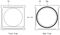
도 4는 본 발명에 따른 열교환용 패널의 후면에 자성체가 설치된 실시예를 도시한 것이고,
도 5는 본 발명에 따른 원심 팬의 전면과 후면에 자성체가 설치된 실시예를 도시한 것이고,
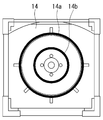
도 6은 본 발명에 따른 케이스의 내측에 자성체가 설치된 실시예를 도시한 것이고,
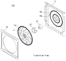
도 7 및 도 8은 본 발명에 따른 슬림형 공기 조화기의 분해 조립도를 도시한 것이고,
도 9는 본 발명에 따른 슬림형 공기 조화기의 측면 분해 조립도를 도시한 것이고,
도 10은 본 발명에 따른 슬림형 공기 조화기의 원심 팬이 기울어지지 않는 실시예를 도시한 것이다. 1 is a view showing a disassembling assembly of a general air conditioner,
2 is a perspective view and a side view of a general air conditioner,
3 shows an embodiment in which a centrifugal fan of a general air conditioner is inclined,
4 shows an embodiment in which a magnetic body is installed on the rear surface of the heat exchange panel according to the present invention,
5 shows an embodiment in which a magnetic body is installed on the front and rear surfaces of the centrifugal fan according to the present invention,
6 shows an embodiment in which a magnetic body is provided inside the case according to the present invention,
7 and 8 show an exploded view of the slim type air conditioner according to the present invention,
9 is a side view of the slim type air conditioner according to the present invention,
FIG. 10 shows an embodiment in which the centrifugal fan of the slim type air conditioner according to the present invention is not tilted.
이하, 본 발명에 따른 슬림형 공기 조화기에 대한 바람직한 실시예에 대해, 첨부된 도면을 참조하여 상세히 설명한다. Hereinafter, preferred embodiments of the slim type air conditioner according to the present invention will be described in detail with reference to the accompanying drawings.
우선, 본 발명에 따른 슬림형 공기 조화기에는, 도 1 내지 도 3을 참조로 전술한 바와 같이, 열교환기 장착용 패널(10), 원심 팬(11), 홀더(12), 모터(13), 그리고 케이스(14) 등이 순차적으로 조립 체결될 수 있다. 1 to 3, the slim type air conditioner according to the present invention includes a heat
한편, 본 발명의 실시예에서는, 예를 들어, 도 4 및 도 5에 도시한 바와 같이, 열교환기 장착용 패널(10)의 후면(Rear)에, 제1 자성체(10a)를 설치함과 아울러, 원심 팬(13)의 전면(Front)에, 제2 자성체(11a)를 설치하게 된다. On the other hand, in the embodiment of the present invention, for example, as shown in Figs. 4 and 5, a first
그리고, 상기 패널(10)의 후면에 설치된 제1 자성체(10a)와, 상기 원심 팬(13)의 전면에 설치된 제2 자성체(11a)가, 동일한 극성(예: N극 또는 S극)으로 서로 마주보기도록 함으로써, 서로 대향되는 이격 위치에서 상호 간에 척력을 발생시키게 된다. The first
한편, 상기 제1 자성체(10a)와 제2 자성체(11a)는, 예를 들어, 환형의 자석으로서, 유연성을 갖는 고무 자석이 사용될 수 있으며, 상기 제1 자성체(10a)는, 도 4에 도시한 바와 같이, 상기 패널(10)의 후면의 중앙에 형성되어 있는 통공의 외주에 설치될 수 있다. The first
그리고, 상기 제2 자성체(11a)는, 도 5에 도시한 바와 같이, 상기 원심 팬(11)의 전면의 외주에 설치되므로, 상기 제1 자성체(10a)와 제2 자성체(11a)가, 서로 마주보는 상태에서, 상호 간에 척력을 발생시키게 된다. 5, the first
한편, 상기 원심 팬(11)의 후면에는, 예를 들어, 도 5에 도시한 바와 같이, 제3 자성체(11b)와 제5 자성체(11c) 중 어느 하나 이상이 설치될 수 있으며, 도 6에 도시한 바와 같이, 상기 케이스(14)의 내측에는, 제4 자성체(14a)와 제6 자성체(14b) 중 어느 하나 이상이 설치될 수 있다. 5, at least one of the third
예를 들어, 상기 제3 자성체(11b)와 제4 자성체(14a)는, 환형의 자석으로서, 상기 제3 자성체(11b)는, 상기 원심 팬(11)의 후면의 외주에 설치되고, 상기 제4 자성체(14a)는, 상기 제3 자성체(11b)와 서로 대향되는 케이스(14)의 내측에 설치되어, 서로 마주보는 상태에서, 상호 간에 척력을 발생시키게 된다. For example, the third
그리고, 상기 제5 자성체(11c)는, 도 5에 도시한 바와 같이, 상기 제3 자성체(11b)의 직경 보다 작은 환형의 좌석으로서, 상기 원심 팬(11)의 후면에 형성된 허브의 외주에 설치된다. 5, the fifth
또한, 상기 제6 자성체(14b)는, 도 6에 도시한 바와 같이, 상기 제4 자성체(14a)의 직경 보다 작은 환형의 자석으로서, 상기 제5 자성체(11c)와 서로 대향되는 케이스(14)의 내측에 설치되어, 상기 제5 자성체(11c)와 서로 마주보는 상태에서, 상호 간에 척력을 발생시키게 된다. 6, the sixth
그러나, 상기 원심 팬(11)의 후면에 설치되는 제5 자성체(11c)와, 상기 케이스(14)의 내측에 설치되는 제6 자성체(14b)는, 공기 조화기의 제조비용 절감을 위해 설치되지 않을 수도 있다. However, the fifth
한편, 도 7 내지 도 9는 본 발명에 따른 슬림형 공기 조화기에 대한 분해 조립도를 도시한 것으로, 본 발명에 따른 슬림형 공기 조화기(110)는, 열교환기 장착용 패널(10), 원심 팬(11), 홀더(12), 모터(13), 그리고 케이스(14) 등이 순차적으로 체결 조립된다.7 to 9 illustrate disassembly and assembly of the slim type air conditioner according to the present invention. The slim
그리고, 상기 패널(10)의 후면에는, 환형의 제1 자성체(10a)가 설치되고, 상기 원심 팬(11)의 전면에는, 환형의 제2 자성체(11a)가 설치된다. An annular first
또한, 상기 원심 팬(11)의 후면에는, 환형의 제3 자성체(11b)와 제5 자성체(11c)가 설치되고, 상기 케이스(14)의 내측에는, 환형의 제4 자성체(14a)와 제6 자성체(14b)가 설치된다.An annular third
즉, 상기 제1 자성체(10a)와 제2 자성체(11a)의 상호 간에 척력이 발생하고, 상기 제3 자성체(11b)와 제4 자성체(14a)의 상호 간에 척력이 발생하며, 상기 제5 자성체(11c)와 제6 자성체(14b)의 상호 간에 척력이 발생하게 된다.That is, a repulsive force is generated between the first
이에 따라, 상기 슬림형 공기 조화기(110)는, 예를 들어, 도 10에 도시한 바와 같이, 상기 패널(10)의 후면과, 상기 원심 팬(11)의 전면 사이의 여유 공간(d2, d2 < d1,)을 좁게 줄여서 제작하더라도, 상기 자성체들에 의해 상호 발생하는 척력에 의해 여유 공간을 일정하게 유지시킬 수 있게 된다. 10, the slim-
따라서, 원심 팬이 회전하는 동안, 상기 자성체들에 의해 상호 발생하는 척력에 의해 진동 발생을 억제하여 소음을 감소시킬 수 있게 된다.Therefore, while the centrifugal fan rotates, the generation of vibration can be suppressed by the repulsive force generated by the magnetic bodies, thereby reducing the noise.
또한, 도 10에 도시한 바와 같이, 상기 원심 팬(11)의 회전 동작이 중지되더라도, 상기 원심 팬(11)의 수직 축(B)이 시계 방향으로 기울어지는 틸트(Tilt) 현상을 방지할 수 있기 때문에, 상기 패널(10)의 후면과, 상기 원심 팬(12)의 전면 사이의 여유 공간(예: d2 = 4mm)을 효율적으로 줄여서, 공기 조화기의 측면 두께를 슬림화할 수 있게 된다. 10, even if the rotation of the
한편, 본 발명의 다른 실시예로서, 상기 원심 팬(11)의 후면의 외주에 제1 자성체(11b)를 설치하고, 상기 케이스(14)의 내측에 제2 자성체(14a)를 설치하되, 상기 제1 자성체(11b)와 제2 자성체(14b)가 서로 마주보도록 대향 설치하는 것만으로도, 원심 팬이 회전하는 동안, 진동 발생을 억제하여 소음을 감소시킬 수 있게 된다. In another embodiment of the present invention, a first
또한, 원심 팬의 회전 동작이 중지되더라도, 틸트(Tilt) 현상을 방지할 수 있게 되므로, 공기 조화기의 측면 두께를 효율적으로 슬림화할 수 있게 된다.In addition, since the tilt phenomenon can be prevented even if the rotation operation of the centrifugal fan is stopped, the lateral thickness of the air conditioner can be effectively slimmed down.
즉, 본 발명의 다른 실시예에서는, 원심 팬(11)의 후면에 제1 자성체(11b)를 설치하고, 케이스(14)의 내측에 제2 자성체(14a)를 설치하는 것을 필수 구성으로 제작한다. That is, in another embodiment of the present invention, the first
그리고, 상기 패널(10)의 후면에 제3 자성체(10a)와 원심 팬(11)의 전면에 제4 자성체(11a)를 설치하는 것과, 상기 원심 팬(11)의 후면에 작은 직경의 제5 자성체(11c)와 케이스(14)의 내측에 작은 직경의 제6 자성체(14b)를 설치하는 것을 선택적 추가 구성하여 제작할 수도 있다. The fourth
이상, 전술한 본 발명의 바람직한 실시예는, 예시의 목적을 위해 개시된 것으로, 당업자라면, 이하 첨부된 특허청구범위에 개시된 본 발명의 기술적 사상과 그 기술적 범위 내에서, 또다른 다양한 실시예들을 개량, 변경, 대체 또는 부가 등이 가능할 것이다.
It will be apparent to those skilled in the art that various modifications and variations can be made in the present invention without departing from the spirit or scope of the invention as defined in the appended claims. , Alteration, substitution, addition, or the like.
100 : 공기 조화기 110 : 슬림형 공기 조화기
10 : 열교환기 장착용 패널 11 : 원심 팬
12 : 모터 홀더 13 : 모터
14 : 케이스 10a,11a,11b,11c,14a,14b : 자성체 100: air conditioner 110: slim type air conditioner
10: Heat exchanger mounting panel 11: Centrifugal fan
12: motor holder 13: motor
14:
Claims (11)
상기 패널의 후면에는, 제1 자성체가 설치되고,
상기 원심 팬의 전면에는, 제2 자성체가 설치되고,
상기 제1 자성체와 제2 자성체는, 서로 대향되는 이격 위치에서, 상호 간에 척력을 발생시키는 것을 특징으로 하는 슬림형 공기 조화기. A heat exchanger mounting panel, a centrifugal fan, a motor, and a case,
A first magnetic body is provided on the rear surface of the panel,
A second magnetic body is provided on the front surface of the centrifugal fan,
Wherein the first magnetic body and the second magnetic body generate a repulsive force mutually at mutually spaced positions.
상기 제1 자성체와 제2 자성체는, 환형의 자석으로서,
상기 제1 자성체는, 상기 패널의 후면의 통공의 외주에 설치되고,
상기 제2 자성체는, 상기 원심 팬의 전면의 외주에 설치되는 것을 특징으로 하는 슬림형 공기 조화기. The method according to claim 1,
Wherein the first magnetic body and the second magnetic body are annular magnets,
Wherein the first magnetic body is provided on the outer periphery of the through hole on the rear surface of the panel,
Wherein the second magnetic body is installed on an outer periphery of a front surface of the centrifugal fan.
상기 원심 팬의 후면에는, 제3 자성체가 설치되고,
상기 케이스의 내측에는, 제4 자성체가 설치되고,
상기 제3 자성체와 제4 자성체, 서로 대향되는 이격 위치에서, 상호 간에 척력을 발생시키는 것을 특징으로 하는 슬림형 공기 조화기.The method according to claim 1,
A third magnetic body is provided on a rear surface of the centrifugal fan,
A fourth magnetic body is provided on the inside of the case,
Wherein the third magnetic body and the fourth magnetic body generate a repulsive force with each other at mutually spaced positions.
상기 제3 자성체와 제4 자성체는, 환형의 자석으로서,
상기 제3 자성체는, 상기 원심 팬의 후면의 외주에 설치되고,
상기 제4 자성체는, 상기 제3 자성체와 서로 대향되는 케이스의 내측에 설치되는 것을 특징으로 하는 슬림형 공기 조화기. The method of claim 3,
Wherein the third magnetic body and the fourth magnetic body are annular magnets,
The third magnetic body is disposed on the outer periphery of the rear surface of the centrifugal fan,
And the fourth magnetic body is disposed inside a case facing the third magnetic body.
상기 원심 팬의 후면에는, 상기 제3 자성체 보다 작은 직경의 제5 자성체가 더 설치되고,
상기 케이스의 내측에는, 상기 제4 자성체 보다 작은 직경의 제6 자성체가 더 설치되고,
상기 제5 자성체와 제6 자성체는, 서로 대향되는 이격 위치에서, 상호 간에 척력을 발생시키는 것을 특징으로 하는 슬림형 공기 조화기.The method of claim 3,
A fifth magnetic body having a smaller diameter than that of the third magnetic body is further provided on a rear surface of the centrifugal fan,
A sixth magnetic body having a smaller diameter than that of the fourth magnetic body is further provided inside the case,
Wherein the fifth magnetic body and the sixth magnetic body generate a repulsive force with each other at mutually spaced positions.
상기 제5 자성체와 제6 자성체는, 환형의 자석으로서,
상기 제5 자성체는, 상기 원심 팬의 후면의 허브의 외주에 설치되고,
상기 제6 자성체는, 상기 제5 자성체와 서로 대향되는 케이스의 내측에 설치되는 것을 특징으로 하는 슬림형 공기 조화기. 6. The method of claim 5,
Wherein the fifth magnetic body and the sixth magnetic body are annular magnets,
The fifth magnetic body is disposed on the outer periphery of the hub on the rear surface of the centrifugal fan,
Wherein the sixth magnetic body is disposed inside a case facing the fifth magnetic body.
상기 원심 팬의 후면에는, 제1 자성체가 설치되고,
상기 케이스의 내측에는, 제2 자성체가 설치되고,
상기 제1 자성체와 제2 자성체는, 서로 대향되는 위치에서, 상호 간에 척력을 발생시키는 것을 특징으로 하는 슬림형 공기 조화기. A heat exchanger mounting panel, a centrifugal fan, a motor, and a case,
A first magnetic body is provided on a rear surface of the centrifugal fan,
A second magnetic body is provided on the inside of the case,
Wherein the first magnetic body and the second magnetic body generate a repulsive force with each other at positions opposed to each other.
상기 제1 자성체와 제2 자성체는, 환형의 자석으로서,
상기 제1 자성체는, 상기 원심 팬의 후면의 외주에 설치되고,
상기 제2 자성체는, 상기 제1 자성체와 서로 대향되는 케이스의 내측에 설치되는 것을 특징으로 하는 슬림형 공기 조화기. 8. The method of claim 7,
Wherein the first magnetic body and the second magnetic body are annular magnets,
The first magnetic body is provided on the outer periphery of the rear surface of the centrifugal fan,
Wherein the second magnetic body is installed inside a case which is opposed to the first magnetic body.
상기 패널의 후면에는, 제3 자성체가 설치되고,
상기 원심 팬의 전면에는, 제4 자성체가 설치되고,
상기 제3 자성체와 제4 자성체는, 서로 대향되는 이격 위치에서, 상호 간에 척력을 발생시키는 것을 특징으로 하는 슬림형 공기 조화기. 8. The method of claim 7,
A third magnetic body is provided on the rear surface of the panel,
A fourth magnetic body is provided on the front surface of the centrifugal fan,
Wherein the third magnetic body and the fourth magnetic body generate a repulsive force with each other at mutually spaced positions.
상기 제3 자성체와 제4 자성체는, 환형의 자석으로서,
상기 제3 자성체는, 상기 패널의 후면의 통공의 외주에 설치되고,
상기 제4 자성체는, 상기 원심 팬의 전면의 외주에 설치되는 것을 특징으로 하는 슬림형 공기 조화기. 10. The method of claim 9,
Wherein the third magnetic body and the fourth magnetic body are annular magnets,
The third magnetic body is provided on the outer periphery of the through hole on the rear surface of the panel,
Wherein the fourth magnetic body is installed on an outer periphery of a front surface of the centrifugal fan.
상기 원심 팬의 후면에는, 상기 제1 자성체 보다 작은 직경의 제5 자성체가 더 설치되고,
상기 케이스의 내측에는, 상기 제2 자성체 보다 작은 직경의 제6 자성체가 더 설치되고,
상기 제5 자성체와 제6 자성체는, 서로 대향되는 이격 위치에서, 상호 간에 척력을 발생시키는 것을 특징으로 하는 슬림형 공기 조화기. 8. The method of claim 7,
A fifth magnetic body having a smaller diameter than that of the first magnetic body is further provided on a rear surface of the centrifugal fan,
A sixth magnetic body having a smaller diameter than that of the second magnetic body is further provided inside the case,
Wherein the fifth magnetic body and the sixth magnetic body generate a repulsive force with each other at mutually spaced positions.
Priority Applications (5)
| Application Number | Priority Date | Filing Date | Title |
|---|---|---|---|
| KR1020120129192A KR20140065026A (en) | 2012-11-15 | 2012-11-15 | Slim type air conditioner |
| US14/079,783 US9435547B2 (en) | 2012-11-15 | 2013-11-14 | Indoor device for an air conditioner |
| CN201380059242.1A CN104797886B (en) | 2012-11-15 | 2013-11-14 | Indoor set for air-conditioning |
| PCT/KR2013/010314 WO2014077592A1 (en) | 2012-11-15 | 2013-11-14 | Indoor device for an air conditioner |
| EP13854416.8A EP2920521B1 (en) | 2012-11-15 | 2013-11-14 | Indoor device for an air conditioner |
Applications Claiming Priority (1)
| Application Number | Priority Date | Filing Date | Title |
|---|---|---|---|
| KR1020120129192A KR20140065026A (en) | 2012-11-15 | 2012-11-15 | Slim type air conditioner |
Publications (1)
| Publication Number | Publication Date |
|---|---|
| KR20140065026A true KR20140065026A (en) | 2014-05-29 |
Family
ID=50680550
Family Applications (1)
| Application Number | Title | Priority Date | Filing Date |
|---|---|---|---|
| KR1020120129192A KR20140065026A (en) | 2012-11-15 | 2012-11-15 | Slim type air conditioner |
Country Status (5)
| Country | Link |
|---|---|
| US (1) | US9435547B2 (en) |
| EP (1) | EP2920521B1 (en) |
| KR (1) | KR20140065026A (en) |
| CN (1) | CN104797886B (en) |
| WO (1) | WO2014077592A1 (en) |
Families Citing this family (2)
| Publication number | Priority date | Publication date | Assignee | Title |
|---|---|---|---|---|
| CN104807096A (en) * | 2015-05-08 | 2015-07-29 | 珠海格力电器股份有限公司 | Indoor unit of air conditioner |
| CN105546661B (en) * | 2016-02-19 | 2018-11-06 | 珠海格力电器股份有限公司 | Air conditioner |
Family Cites Families (10)
| Publication number | Priority date | Publication date | Assignee | Title |
|---|---|---|---|---|
| KR0123022B1 (en) * | 1995-03-20 | 1997-12-01 | 구자홍 | Combining structure of airconditioner |
| JPH10288196A (en) * | 1997-04-16 | 1998-10-27 | Daikin Ind Ltd | Turbo fan device |
| KR20060093985A (en) | 2005-02-23 | 2006-08-28 | 엘지전자 주식회사 | Air conditioner |
| KR101181545B1 (en) * | 2005-10-26 | 2012-09-10 | 엘지전자 주식회사 | Indoor unit for air conditioner |
| TWI293106B (en) * | 2005-11-22 | 2008-02-01 | Sunonwealth Electr Mach Ind Co | Thin-type fan |
| AU2006337754B2 (en) | 2006-02-07 | 2010-02-18 | Lg Electronics Inc. | Indoor unit of air conditioner |
| KR101474425B1 (en) | 2008-01-21 | 2014-12-22 | 엘지전자 주식회사 | Fan assembly for refrigerator |
| US20110280753A1 (en) | 2010-05-12 | 2011-11-17 | Chien-Chang Chen | Tilt-preventing fan |
| TWM423280U (en) | 2011-05-26 | 2012-02-21 | Delta Electronics Inc | Fan |
| KR101918225B1 (en) * | 2012-02-15 | 2018-11-13 | 엘지전자 주식회사 | Indoor unit |
-
2012
- 2012-11-15 KR KR1020120129192A patent/KR20140065026A/en not_active Application Discontinuation
-
2013
- 2013-11-14 US US14/079,783 patent/US9435547B2/en active Active
- 2013-11-14 WO PCT/KR2013/010314 patent/WO2014077592A1/en active Application Filing
- 2013-11-14 EP EP13854416.8A patent/EP2920521B1/en active Active
- 2013-11-14 CN CN201380059242.1A patent/CN104797886B/en active Active
Also Published As
| Publication number | Publication date |
|---|---|
| EP2920521B1 (en) | 2019-10-09 |
| CN104797886A (en) | 2015-07-22 |
| US20140131018A1 (en) | 2014-05-15 |
| EP2920521A4 (en) | 2016-07-27 |
| WO2014077592A1 (en) | 2014-05-22 |
| CN104797886B (en) | 2017-07-25 |
| EP2920521A1 (en) | 2015-09-23 |
| US9435547B2 (en) | 2016-09-06 |
Similar Documents
| Publication | Publication Date | Title |
|---|---|---|
| JP4788409B2 (en) | Cross current blower and electronic device | |
| JP4539659B2 (en) | Fan motor device and electronic device | |
| US10590936B2 (en) | Electrically driven pump and method for manufacturing the same | |
| US8147203B2 (en) | Fan | |
| US20100189544A1 (en) | Counter-rotating axial-flow fan | |
| US10184492B2 (en) | Axial flow fan | |
| EP3144497A1 (en) | Electric supercharger | |
| JP2012229689A (en) | Cooling fan | |
| JP2010031659A (en) | Serial axial fan | |
| CN107834750B (en) | Outer rotor brushless motor | |
| KR20140065026A (en) | Slim type air conditioner | |
| US8231333B2 (en) | Fan unit having a fan | |
| JP6470055B2 (en) | Electric blower and electric vacuum cleaner using the same | |
| EP3657025B1 (en) | Cross-flow impeller device and cooling fan | |
| JP2010110117A (en) | Permanent magnet motor | |
| WO2017086124A1 (en) | Fan unit and outdoor unit | |
| US10215195B2 (en) | Vibration isolation system for a fan motor | |
| JP2009091962A (en) | Centrifugal fan | |
| JP6600277B2 (en) | Axial fan | |
| JP5315949B2 (en) | Air conditioner | |
| WO2020031630A1 (en) | Blower unit and mounting structure therefor | |
| JP2011166189A (en) | Heat dissipation mechanism for flat display television set | |
| WO2016056046A1 (en) | Fan holder | |
| JP2018019549A (en) | Rotary electric machine | |
| JP2016151229A (en) | Method for inhibiting vibration of centrifugal fan unit, centrifugal fan unit, and portable computer |
Legal Events
| Date | Code | Title | Description |
|---|---|---|---|
| A201 | Request for examination | ||
| E902 | Notification of reason for refusal | ||
| E601 | Decision to refuse application |