EP2920451B1 - Lufteinlasssystem für ein werksfahrzeug - Google Patents
Lufteinlasssystem für ein werksfahrzeug Download PDFInfo
- Publication number
- EP2920451B1 EP2920451B1 EP13766176.5A EP13766176A EP2920451B1 EP 2920451 B1 EP2920451 B1 EP 2920451B1 EP 13766176 A EP13766176 A EP 13766176A EP 2920451 B1 EP2920451 B1 EP 2920451B1
- Authority
- EP
- European Patent Office
- Prior art keywords
- blower
- outlet
- intake system
- air intake
- cleaner
- Prior art date
- Legal status (The legal status is an assumption and is not a legal conclusion. Google has not performed a legal analysis and makes no representation as to the accuracy of the status listed.)
- Active
Links
- 239000002828 fuel tank Substances 0.000 claims description 13
- 239000012530 fluid Substances 0.000 claims description 12
- 238000004891 communication Methods 0.000 claims description 10
- 238000011144 upstream manufacturing Methods 0.000 claims description 7
- 239000003570 air Substances 0.000 description 63
- 230000005540 biological transmission Effects 0.000 description 3
- 239000000428 dust Substances 0.000 description 3
- 238000002485 combustion reaction Methods 0.000 description 2
- 238000001914 filtration Methods 0.000 description 2
- 239000000463 material Substances 0.000 description 2
- 238000012986 modification Methods 0.000 description 2
- 230000004048 modification Effects 0.000 description 2
- 238000009987 spinning Methods 0.000 description 2
- 241000555745 Sciuridae Species 0.000 description 1
- 239000012080 ambient air Substances 0.000 description 1
- 230000000712 assembly Effects 0.000 description 1
- 238000000429 assembly Methods 0.000 description 1
- 230000003247 decreasing effect Effects 0.000 description 1
- 238000005516 engineering process Methods 0.000 description 1
- 239000000446 fuel Substances 0.000 description 1
- 230000005484 gravity Effects 0.000 description 1
- 238000003306 harvesting Methods 0.000 description 1
- 230000010355 oscillation Effects 0.000 description 1
- 230000035939 shock Effects 0.000 description 1
Images


Classifications
-
- F—MECHANICAL ENGINEERING; LIGHTING; HEATING; WEAPONS; BLASTING
- F02—COMBUSTION ENGINES; HOT-GAS OR COMBUSTION-PRODUCT ENGINE PLANTS
- F02M—SUPPLYING COMBUSTION ENGINES IN GENERAL WITH COMBUSTIBLE MIXTURES OR CONSTITUENTS THEREOF
- F02M35/00—Combustion-air cleaners, air intakes, intake silencers, or induction systems specially adapted for, or arranged on, internal-combustion engines
- F02M35/16—Combustion-air cleaners, air intakes, intake silencers, or induction systems specially adapted for, or arranged on, internal-combustion engines characterised by use in vehicles
- F02M35/161—Arrangement of the air intake system in the engine compartment, e.g. with respect to the bonnet or the vehicle front face
-
- F—MECHANICAL ENGINEERING; LIGHTING; HEATING; WEAPONS; BLASTING
- F02—COMBUSTION ENGINES; HOT-GAS OR COMBUSTION-PRODUCT ENGINE PLANTS
- F02M—SUPPLYING COMBUSTION ENGINES IN GENERAL WITH COMBUSTIBLE MIXTURES OR CONSTITUENTS THEREOF
- F02M35/00—Combustion-air cleaners, air intakes, intake silencers, or induction systems specially adapted for, or arranged on, internal-combustion engines
- F02M35/16—Combustion-air cleaners, air intakes, intake silencers, or induction systems specially adapted for, or arranged on, internal-combustion engines characterised by use in vehicles
- F02M35/164—Heavy duty vehicles, e.g. trucks, trains, agricultural or construction machines
-
- B—PERFORMING OPERATIONS; TRANSPORTING
- B01—PHYSICAL OR CHEMICAL PROCESSES OR APPARATUS IN GENERAL
- B01D—SEPARATION
- B01D45/00—Separating dispersed particles from gases or vapours by gravity, inertia, or centrifugal forces
- B01D45/12—Separating dispersed particles from gases or vapours by gravity, inertia, or centrifugal forces by centrifugal forces
- B01D45/16—Separating dispersed particles from gases or vapours by gravity, inertia, or centrifugal forces by centrifugal forces generated by the winding course of the gas stream, the centrifugal forces being generated solely or partly by mechanical means, e.g. fixed swirl vanes
-
- B—PERFORMING OPERATIONS; TRANSPORTING
- B01—PHYSICAL OR CHEMICAL PROCESSES OR APPARATUS IN GENERAL
- B01D—SEPARATION
- B01D46/00—Filters or filtering processes specially modified for separating dispersed particles from gases or vapours
-
- B—PERFORMING OPERATIONS; TRANSPORTING
- B01—PHYSICAL OR CHEMICAL PROCESSES OR APPARATUS IN GENERAL
- B01D—SEPARATION
- B01D50/00—Combinations of methods or devices for separating particles from gases or vapours
- B01D50/20—Combinations of devices covered by groups B01D45/00 and B01D46/00
-
- B—PERFORMING OPERATIONS; TRANSPORTING
- B60—VEHICLES IN GENERAL
- B60K—ARRANGEMENT OR MOUNTING OF PROPULSION UNITS OR OF TRANSMISSIONS IN VEHICLES; ARRANGEMENT OR MOUNTING OF PLURAL DIVERSE PRIME-MOVERS IN VEHICLES; AUXILIARY DRIVES FOR VEHICLES; INSTRUMENTATION OR DASHBOARDS FOR VEHICLES; ARRANGEMENTS IN CONNECTION WITH COOLING, AIR INTAKE, GAS EXHAUST OR FUEL SUPPLY OF PROPULSION UNITS IN VEHICLES
- B60K13/00—Arrangement in connection with combustion air intake or gas exhaust of propulsion units
- B60K13/02—Arrangement in connection with combustion air intake or gas exhaust of propulsion units concerning intake
-
- F—MECHANICAL ENGINEERING; LIGHTING; HEATING; WEAPONS; BLASTING
- F02—COMBUSTION ENGINES; HOT-GAS OR COMBUSTION-PRODUCT ENGINE PLANTS
- F02M—SUPPLYING COMBUSTION ENGINES IN GENERAL WITH COMBUSTIBLE MIXTURES OR CONSTITUENTS THEREOF
- F02M35/00—Combustion-air cleaners, air intakes, intake silencers, or induction systems specially adapted for, or arranged on, internal-combustion engines
- F02M35/02—Air cleaners
- F02M35/0212—Multiple cleaners
- F02M35/0215—Multiple cleaners arranged in parallel
-
- F—MECHANICAL ENGINEERING; LIGHTING; HEATING; WEAPONS; BLASTING
- F02—COMBUSTION ENGINES; HOT-GAS OR COMBUSTION-PRODUCT ENGINE PLANTS
- F02M—SUPPLYING COMBUSTION ENGINES IN GENERAL WITH COMBUSTIBLE MIXTURES OR CONSTITUENTS THEREOF
- F02M35/00—Combustion-air cleaners, air intakes, intake silencers, or induction systems specially adapted for, or arranged on, internal-combustion engines
- F02M35/02—Air cleaners
- F02M35/022—Air cleaners acting by gravity, by centrifugal, or by other inertial forces, e.g. with moistened walls
- F02M35/0223—Air cleaners acting by gravity, by centrifugal, or by other inertial forces, e.g. with moistened walls by centrifugal forces, e.g. cyclones
-
- F—MECHANICAL ENGINEERING; LIGHTING; HEATING; WEAPONS; BLASTING
- F02—COMBUSTION ENGINES; HOT-GAS OR COMBUSTION-PRODUCT ENGINE PLANTS
- F02M—SUPPLYING COMBUSTION ENGINES IN GENERAL WITH COMBUSTIBLE MIXTURES OR CONSTITUENTS THEREOF
- F02M35/00—Combustion-air cleaners, air intakes, intake silencers, or induction systems specially adapted for, or arranged on, internal-combustion engines
- F02M35/02—Air cleaners
- F02M35/024—Air cleaners using filters, e.g. moistened
-
- F—MECHANICAL ENGINEERING; LIGHTING; HEATING; WEAPONS; BLASTING
- F02—COMBUSTION ENGINES; HOT-GAS OR COMBUSTION-PRODUCT ENGINE PLANTS
- F02M—SUPPLYING COMBUSTION ENGINES IN GENERAL WITH COMBUSTIBLE MIXTURES OR CONSTITUENTS THEREOF
- F02M35/00—Combustion-air cleaners, air intakes, intake silencers, or induction systems specially adapted for, or arranged on, internal-combustion engines
- F02M35/02—Air cleaners
- F02M35/08—Air cleaners with means for removing dust, particles or liquids from cleaners; with means for indicating clogging; with by-pass means; Regeneration of cleaners
- F02M35/086—Dust removal by flushing, blasting, pulsating or aspirating flow, washing or the like; Mechanical dust removal, e.g. by using scrapers
Definitions
- the present subject matter relates generally to work vehicles and, more particularly, to an air intake system for a work vehicle that includes an electric blower configured to aspirate a pre-cleaner of the air intake system.
- Work vehicles typically include internal combustion engines that require clean air for use within the combustion process. Since many work vehicles, such as tractors and other agricultural vehicles, operate in fields and other harvesting environments in which the ambient air contains large amounts of dust, plant material and other particulates, an air intake system having an effective filter assembly is required.
- conventional filter assemblies for work vehicles typically include a vortex or cyclone pre-cleaner configured to separate large particulates from the intake air and a porous air filter downstream of the pre-cleaner to provide the final stage of filtering prior to delivering the air into the engine.
- the large particulates separated from the intake air by the pre-cleaner must be removed from the filter assembly.
- such particulates are removed from the filter assembly via an outlet duct using a vacuum generated by the exhaust flow from the engine.
- the vacuum generated by the exhaust flow is often insufficient to meet the performance requirements of the filter assembly, thereby causing the air filter to plug within a short period of time.
- U.S. Pat. Pub. No. 2011/0072769 discloses an air intake system including a fan module mounted directly to the filter assembly which is dedicated to delivering a vacuum that sucks particulates from the pre-cleaner.
- the fan module includes a fan and a motor housed within a sleeve, with a rotational axis of the fan and the motor being concentrically aligned with a central axis of the sleeve.
- particulates are sucked from the pre-cleaner and flow through the sleeve along a flow path radially aligned with and extending parallel to the rotational axis of the fan and the motor. As such, the particulates may be directed into the motor, itself, which can result in significant damage to the motor.
- DE-10128790A1 Another example of such a system is shown in DE-10128790A1 .
- an air intake system including an electric blower that can effectively remove particulates from the pre-cleaner while decreasing risk of damage to the blower's motor would be welcomed in the technology.
- the present subject matter is directed to an air intake system for a work vehicle.
- the air intake system may generally include a filter assembly having a pre-cleaner configured to separate particulates from air received within the filter assembly.
- the pre-cleaner may define a pre-cleaner outlet.
- the air intake system may also include a conduit extending between an upstream end and a downstream end. The upstream end of the conduit may be in fluid communication with the pre-cleaner outlet.
- the air intake system may include a blower having a fan and a housing encasing the fan. The housing may define a blower inlet in fluid communication with the downstream end of the conduit.
- the fan may be configured to create a vacuum such that the particulates separated from the air are expelled from the pre-cleaner outlet and flow through the conduit and into the housing.
- the housing may further define a blower outlet through which the particulates are expelled from the housing. The flow of particulates through the blower outlet may be oriented non-parallel to a rotational axis of the fan.
- the present subject matter is directed to an air intake system for a work vehicle.
- the air intake system may generally include a filter assembly having a pre-cleaner configured to separate particulates from air received within the filter assembly.
- the pre-cleaner may define a pre-cleaner outlet.
- the air intake system may also include a conduit extending between an upstream end and a downstream end. The upstream end may be in fluid communication with the pre-cleaner outlet.
- the air intake system may include a blower having a fan and a housing encasing the fan. The housing may define a blower inlet in fluid communication with the downstream end of the conduit.
- the fan may be configured to create a vacuum such that the particulates separated from the air are expelled from the outlet port and flow through the conduit and into the housing.
- the housing may further define a blower outlet through which the particulates are expelled from the housing.
- the blower may be spaced apart from the filter assembly and may be supported by a separate component of the work vehicle.
- the present subject matter is directed to an air intake system for a work vehicle.
- the air intake system may include a filter assembly having a pre-cleaner configured to separate particulates from the air flowing into the system and an air filter disposed downstream of the pre-cleaner.
- the air intake system may include an electric blower configured to aspirate the pre-cleaner by creating a vacuum that sucks the particulates out of the pre-cleaner.
- the blower may be spaced apart from the filter assembly and may be completely supported by a separate component of the work vehicle (e.g., a fuel tank of the work vehicle).
- the blower may be configured such that the particulates flowing into the blower are directed away from blower's motor, thereby preventing damage to the motor.
- FIG. 1 illustrates a side view of one embodiment of a work vehicle 10.
- the work vehicle 10 is configured as an agricultural tractor.
- the work vehicle 10 may be configured as any other suitable work vehicle known in the art, such as various other agricultural vehicles, earth-moving vehicles, road vehicles, loaders and/or the like.
- the work vehicle 10 includes a pair of front wheels 12, a pair or rear wheels 14 and a chassis 16 coupled to and supported by the wheels 12, 14.
- An operator's cab 18 may be supported by a portion of the chassis 16 and may house various control devices 20 (e.g., levers, pedals, control panels and/or the like) for permitting an operator to control the operation of the work vehicle 10.
- the work vehicle 10 may include an engine 22 and a transmission 24 mounted on the chassis 16.
- the transmission 24 may be operably coupled to the engine 22 and may provide variably adjusted gear ratios for transferring engine power to the wheels 14 via a differential 26.
- the engine 22, transmission 24, and differential 26 may collectively define a drive train 28 of the work vehicle 10.
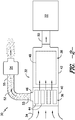
- the air intake system 30 may generally include a filter assembly 32 configured to receive dirty air from an intake duct 34 and clean/filter such air for subsequent delivery to the engine 22.
- the filter assembly 32 may include a pre-cleaner 36 and an air filter 38 disposed downstream of the pre-cleaner 36.
- the filter assembly 32 may include a pre-cleaner housing 40 configured to encase the pre-cleaner 36 and a filter housing 42 configured to encase the air filter 38.
- pre-cleaner housing 40 and the filter housing may 42 be formed integrally with one another (e.g., by forming both housings 40, 42 as a single continuous housing) or the pre-cleaner housing 40 and the filter housing 42 may comprise separate components configured to be separately coupled to one another
- the pre-cleaner 36 may be configured to remove portions of the dust, dirt, debris, plant matter and other particulates contained within the air flowing into the filter assembly 32 via the intake duct 34.
- the pre-cleaner 36 may include a plurality of tubes (e.g., turbo tubes), dirt separators, and/or any other suitable pre-cleaner elements 44 configured to separate particulates from the air via centripetal force.
- the pre-cleaner elements 44 may be configured to impart a vortex or spinning motion to the flow of air entering the filter assembly 32.
- pre-cleaner outlet 46 an outlet port 46 defined in the pre-cleaner housing 40 (hereinafter referred to as the "pre-cleaner outlet 46").
- the air filter 38 may generally be configured to receive the cleaned air flowing from the pre-cleaner 36 and filter such air to provide a final stage of filtering prior to delivery of the air to the engine 22.
- the air filter 38 may generally include one or more filter elements 48 configured to catch or trap the remaining particulates contained within the cleaned air.
- the filter element(s) 48 may be made from a fibrous, porous or mesh material that allows air to pass therethrough while catching/trapping any particulates. The cleaned/filtered air may then be directed through a suitable conduit 50 to the engine 22, where the air may be mixed with fuel and combusted.
- the disclosed air intake system 30 may also include a conduit 52 having an upstream end 53 in fluid communication with the pre-cleaner outlet 46 and a downstream end 55 in fluid communication with an electric blower 54 configured to aspirate the pre-cleaner 36.
- the blower 54 may be configured to generate a vacuum that sucks the particulate flowing along the inner wall of the pre-cleaner housing 40 out the pre-cleaner outlet 46 and through the conduit 52. The particulate may then be expelled from the blower 54 back into the environment.
- the conduit 52 may generally be any suitable elongated member configured for the flow of air and/or fluid therethrough.
- the conduit 52 may comprise a tube, hose, pipe, duct and/or any other conduit-like member defining a passageway for the flow of air/fluid.
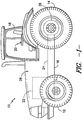
- FIG. 3 illustrates a perspective view of various components of the air intake system 30 mounted to or otherwise supported by a fuel tank 56 of the work vehicle 10.
- FIG. 4 illustrates a cross-sectional view of the blower 54 shown in FIG. 3 , particularly illustrating a cross-sectional view in a widthwise direction of the blower 54 (indicated by the arrow 58 in FIG. 3 ).
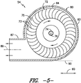
- FIG. 5 illustrates another cross-sectional view of the blower shown in FIG. 3 , particularly illustrating a cross-sectional view in a crosswise direction of the blower 54 (indicated by the arrow 60 in FIG. 3 ).
- the pre-cleaner housing 40 and the filter housing 42 may be oriented generally perpendicularly to one another such that the filter assembly 32 generally defines an "L" shape. As such, the air flowing into the intake duct 34 may be directed generally vertically downward through the pre-cleaner 36 and then generally horizontally through the air filter 38.
- the pre-cleaner housing 40 and the filter housing 42 may have any other suitable orientation relative to one another.
- the pre-cleaner housing 40 and the filter housing 42 may be aligned along a common axis such that air flowing through the filter assembly 32 is directed continuously along such axis (e.g., similar to the schematic view of the filter assembly 32 shown in FIG. 2 ).
- the filter assembly 32 may be coupled to or otherwise supported by a fuel tank 56 of the work vehicle 10.
- the fuel tank 56 may be molded or otherwise formed so as to define a recessed feature configured to receive a portion of the filter assembly 32.
- a top 62 of the fuel tank 56 may define a semi-circular recessed feature 64 such that a portion of the cylindrical filter housing 42 and/or pre-cleaner housing 40 may be received within the recessed feature 64.
- the filter assembly 32 may simply be coupled to the fuel tank 56 without being received within any type of recessed feature 64.
- the filter assembly 32 may be disposed at any other suitable location on and/or within the work vehicle 10 and, thus, may be coupled to and/or supported by any other suitable component of the work vehicle 10.
- the blower 54 of the air intake system 30 may also be coupled to or otherwise supported by the fuel tank 56.
- one or more suitable mounting brackets 66 may be coupled between a side 68 of the fuel tank 56 and the blower 54 to allow the blower 54 to be secured to and supported by the fuel tank 56.
- the blower 54 may be disposed at any other suitable location on and/or within the work vehicle 10 and, thus, may be coupled to and/or supported by any other suitable component of the work vehicle 10.
- blower 54 By configuring the blower 54 to be spaced apart from the filter assembly 32, it should be appreciated that numerous advantages may be provided to the disclosed air intake system 30. For example, when the blower 54 is directly mounted to or otherwise directly supported by the filter assembly 32, the blower may often be subject to vibrations or oscillations transferred from the filter assembly 32 during operation of the work vehicle 10. However, by rigidly mounting the blower 54 to a separate component of the work vehicle 10 (e.g., the fuel tank 56), a degree of vibration dampening may be achieved. In addition, since the conduit 52 may be designed to have any suitable length and/or shape that permits the blower 54 to be in fluid communication with the pre-cleaner 44, the blower 54 may be positioned at a more desirable location than directly adjacent to the filter assembly 32.
- the blower 54 may be disposed at a lower position on the work vehicle 10, thereby reducing the amount of shock transmitted to the blower 54 and allowing the particulate expelled from the blower 54 to be directed away from the work vehicle 10 and onto the ground.
- the blower 54 may be disposed at a location that is hidden from view, such as at a location underneath a set of steps (not shown) extending adjacent to the fuel tank 56.
- the disclosed blower 54 may generally include an electric motor 70 configured to rotationally drive a fan 72 such that a negative pressure or vacuum is generated within the blower 54 and the conduit 52 that is capable of aspirating the pre-cleaner 36.
- the fan 72 may be mounted to an output shaft 74 of the motor 70 such that rotation of the output shaft 74 rotationally drives the fan 72 about a rotational axis 76 of the motor 70.
- the motor 70 may be configured to rotate the fan 72 at a constant speed or a variable speed.
- the rotational speed of the motor 70 may be electronically controlled via a controller 78 of the work vehicle 10 (e.g., a computer and/or other suitable processing device).
- the rotational speed of the motor/fan 70,72 and, thus, the suction of the vacuum generated within the blower 54 may be controlled independent of the engine speed, exhaust flow and/or any other operating parameters of the work vehicle 10.
- the fan 72 may generally have any suitable configuration that permits it to function as described herein.
- the fan may be configured as a blower or centrifugal fan (also referred to as a squirrel cage fan) and may include a plurality of blades 73 (e.g., straight radial blades, forward-curved blades or backwards-curved blades) mounted to a suitable base or hub 75.
- a blower or centrifugal fan also referred to as a squirrel cage fan
- blades 73 e.g., straight radial blades, forward-curved blades or backwards-curved blades
- the blower 54 may also include a housing 80 configured to encase and/or support the motor 70 and the fan 72.
- the housing 80 may be generally cylindrically shaped and may include a first endwall 81, a second endwall 82 and a circumferential sidewall 83 extending between the first and second endwalls 81, 82.
- the endwalls 81, 82 and the sidewall 83 may generally define an enclosed, cylindrical volume 84 (hereinafter referred to as the "fan compartment 84") within which the fan 72 may be rotationally disposed.
- the motor 70 may be coupled to the housing 80 (e.g., using suitable mechanical fasteners, such as bolts, screws, brackets and/or the like) in a manner that permits the motor 70 to rotationally drive the fan 72 within the fan compartment 84.
- suitable mechanical fasteners such as bolts, screws, brackets and/or the like
- an opening 85 may be defined in the first endwall 81 such that, when the motor 70 is coupled to the housing 80, the output shaft 74 may extend through the opening 85 in order to rotationally drive the fan 72.
- the blower 54 may include a blower inlet 86 and a blower outlet 87 defined by the housing 80.
- the blower inlet 86 may be configured to be in fluid communication with the conduit 52 such that particulate flowing through the conduit 52 may be directed into the fan compartment 84 via the blower inlet 86.
- the housing 80 may be configured such that the blower inlet 86 is defined by the second endwall 82 of the housing 80.
- blower inlet 86 may, for example, be positioned along the second endwall 82 such that an inlet centerline 88 of the blower inlet 86 is generally aligned with and/or extends parallel to the rotational axis 76 of the motor/fan 70, 72. As such, the flow of particulate through the blower inlet 86 and into the fan compartment 84 may be directed along a flow path that is generally parallel to the rotational axis 76.
- the blower inlet 86 may be defined at any other suitable location on the housing 80 and the inlet centerline 88 may have any other suitable orientation relative to the rotational axis 76.
- the blower outlet 87 may generally correspond to an opening defined by the housing through which the particulate flowing into the fan compartment 84 is expelled from the blower 54.
- the housing 80 may be configured such that the blower outlet 54 forms an outward extension of the cylindrical sidewall 83.
- the blower outlet 87 may be configured to extend outwardly from the sidewall 83 such that an outlet centerline 89 of the blower outlet 87 extends generally perpendicular to the rotational axis 76 of the motor/fan 70,72 (and, optionally, the inlet centerline 88) and generally parallel to a tangent line 90 defined by the outer surface of the sidewall 83. Additionally, as shown in FIG.
- the outlet centerline 89 may also be radially offset from the rotational axis 76 (and, optionally, the inlet centerline 86). As such, the flow of particulates entering the blower 54 along the inlet centerline 86 may be redirected within the fan compartment 84 prior to being expelled through the blower outlet 87.
- the component life of the motor 70 may enhanced significantly.
- the first endwall 81 of the housing 80 may generally serve to protect the motor from the particulates flowing into the fan compartment 84.
- the blower inlet 86 and outlet 88 the particulates entering the fan compartment 84 may be redirected away from the rotational axis 76 of the motor/fan 70, 72 towards the blower outlet 86. As such, any damage that may have otherwise occurred due to dirt, dust and/or other particulates flowing between the output shaft 74 and the first endwall 81 and into the motor 70 may be avoided.
- the blower outlet 87 may be configured to have any other suitable orientation in which the outlet centerline 89 extends non-parallel to and/or is radially offset from the rotational axis 76 of the motor/fan 70, 71.
- the blower outlet 87 may be configured to extend from the sidewall 83 such that the outlet centerline 89 is oriented relative to the rotational axis 76 at an angle that is less than 90 degrees or greater than 90 degrees.
- the blower outlet 87 may be configured to extend from the first or second endwall 81, 82 such that the outlet centerline 89 is parallel to, but radially offset from, the rotational axis 76.
- the blower outlet 87 may be configured to be positioned along a bottom portion of the housing 80.
- the blower outlet 87 may extend from a bottom half of the sidewall 83 (e.g. by extending parallel to the tangent line 90 defined at the very bottom of the housing 80).
- gravity may pull the particulates downward within the fan compartment 84, thereby assisting in directing the particulates towards the blower outlet 87.
Landscapes
- Engineering & Computer Science (AREA)
- Chemical & Material Sciences (AREA)
- Combustion & Propulsion (AREA)
- Mechanical Engineering (AREA)
- General Engineering & Computer Science (AREA)
- Chemical Kinetics & Catalysis (AREA)
- Transportation (AREA)
- Filtering Of Dispersed Particles In Gases (AREA)
- Structures Of Non-Positive Displacement Pumps (AREA)
- Processes For Solid Components From Exhaust (AREA)
- Component Parts Of Construction Machinery (AREA)
Claims (9)
- Lufteinlasssystem (30) für ein Arbeitsfahrzeug (10), wobei das Lufteinlasssystem (30) aufweist:- eine Filteranordnung (32) mit einer Vorreinigungseinrichtung (36), die dazu eingerichtet ist, Partikel von Luft zu trennen, die durch die Filteranordnung (32) aufgenommen werden, wobei die Vorreinigungseinrichtung (36) einen Vorreinigungsauslass (46) definiert;- ein Rohr (52), das sich zwischen einem stromauf gelegenen Ende und einem stromab gelegenen Ende erstreckt, wobei das stromauf gelegene Ende in Fluidkommunikation mit dem Vorreinigungsauslass (46) ist; und- eine Gebläseeinrichtung (54) mit einem Lüfterrad (72) und einem Gehäuse (80), das den Lüfter (72) einschließt, wobei das Gehäuse (80) einen Gebläseeinlass (86) in Fluidkommunikation mit dem stromab gelegenen Ende des Rohres (52) definiert, wobei das Lüfterrad (72) dazu eingerichtet ist, um ein Vakuum zu erzeugen, so dass die von der Luft innerhalb der Vorreinigungseinrichtung (36) abgetrennten Partikel aus dem Vorreinigungsauslass (46) ausgestoßen werden und durch das Rohr (52) und in das Gehäuse (80) fließen, wobei das Gehäuse (80) des Weiteren einen Gebläseauslass (87) definiert, durch den die Partikel von dem Gehäuse (80) ausgestoßen werden,wobei der Partikelfluss durch den Gebläseauslass (87) nicht parallel zu einer Rotationsachse des Lüfters (76) ausgerichtet ist; und
dadurch gekennzeichnet, dass
das Gehäuse (80) eine erste Endwand (81), eine zweite Endwand (82), die gegenüber der ersten Endwand (81) angeordnet ist, und eine Seitenwand (83) umfasst, die sich zwischen den ersten und zweiten Endwänden (81, 82) erstreckt, wobei die Gebläseeinrichtung (54) des Weiteren einen Motor (70) aufweist, der dazu eingerichtet ist, das Lüfterrad (72) in Rotation zu versetzen, wobei der Motor (70) an einer der ersten Endwand (81) oder der zweiten Endwand (82) angebracht ist, wobei der Gebläseeinlass (86) durch die andere der ersten Endwand (81) oder zweiten Endwand (82) definiert ist. - Lufteinlasssystem (30) nach Anspruch 1, wobei der Gebläseauslass (87) durch die Seitenwand (83) definiert ist.
- Lufteinlasssystem (30) nach Anspruch 2, wobei der Gebläseauslass (87) eine Auslassmittellinie (89) definiert, wobei sich die Auslassmittellinie (89) parallel zu einer Tangente (90) erstreckt, die durch die Seitenwand (83) definiert ist.
- Lufteinlasssystem (30) nach Anspruch 2, wobei der Gebläseauslass (87) sich von einem unteren Abschnitt der Seitenwand (83) erstreckt.
- Lufteinlasssystem (30) nach Anspruch 1, wobei der Gebläseauslass (87) eine Auslassmittellinie (89) definiert und der Gebläseeinlass (86) eine Einlassmittellinie (88) definiert, wobei die Auslassmittellinie (89) sich senkrecht zu der Einlassmittellinie (88) erstreckt.
- Lufteinlasssystem (30) nach Anspruch 1, wobei der Gebläseauslass (87) eine Auslassmittellinie (89) definiert, wobei sich die Auslassmittellinie (89) senkrecht zu der Rotationsachse des Lüfterrads (76) erstreckt.
- Lufteinlasssystem (30) nach Anspruch 1, wobei die Gebläseeinrichtung (54) von der Filteranordnung (32) beabstandet ist und von einem getrennten Bestandteil des Arbeitsfahrzeugs (10) getragen ist.
- Lufteinlasssystem (30) nach Anspruch 7, wobei die Gebläseeinrichtung (54) mit einem Kraftstofftank (56) des Arbeitsfahrzeugs (10) gekoppelt ist.
- Lufteinlasssystem (30) nach Anspruch 8, wobei der Kraftstofftank (56) eine Oberseite umfasst, die ein Vertiefungselement (64) definiert, wobei mindestens ein Abschnitt der Filteranordnung (32) innerhalb des Vertiefungselements (64) aufgenommen ist.
Applications Claiming Priority (2)
| Application Number | Priority Date | Filing Date | Title |
|---|---|---|---|
| US201261726229P | 2012-11-14 | 2012-11-14 | |
| PCT/US2013/058367 WO2014077938A1 (en) | 2012-11-14 | 2013-09-06 | Air intake system for a work vehicle |
Publications (2)
| Publication Number | Publication Date |
|---|---|
| EP2920451A1 EP2920451A1 (de) | 2015-09-23 |
| EP2920451B1 true EP2920451B1 (de) | 2017-12-13 |
Family
ID=49230850
Family Applications (1)
| Application Number | Title | Priority Date | Filing Date |
|---|---|---|---|
| EP13766176.5A Active EP2920451B1 (de) | 2012-11-14 | 2013-09-06 | Lufteinlasssystem für ein werksfahrzeug |
Country Status (5)
| Country | Link |
|---|---|
| US (1) | US20150275831A1 (de) |
| EP (1) | EP2920451B1 (de) |
| CN (1) | CN104781539A (de) |
| BR (1) | BR112015011043B1 (de) |
| WO (1) | WO2014077938A1 (de) |
Families Citing this family (11)
| Publication number | Priority date | Publication date | Assignee | Title |
|---|---|---|---|---|
| USD834064S1 (en) * | 2014-04-17 | 2018-11-20 | Deere & Company | Display screen or portion thereof with icon |
| US9273649B2 (en) * | 2014-05-30 | 2016-03-01 | Cnh Industrial America Llc | System and method for controlling an electric aspirator of an air intake system for a work vehicle |
| US9957929B2 (en) * | 2014-07-08 | 2018-05-01 | Cnh Industrial America Llc | System and method for capturing cleaner intake air for use within an air intake system of a work vehicle |
| USD761306S1 (en) * | 2014-07-23 | 2016-07-12 | Deere & Company | Display screen or portion thereof with icon |
| US9689334B2 (en) | 2014-11-14 | 2017-06-27 | Cnh Industrial America Llc | Air intake system for an off-road vehicle |
| US20160305375A1 (en) * | 2015-04-15 | 2016-10-20 | Caterpillar Inc. | Filter assembly |
| WO2017196367A1 (en) * | 2016-05-13 | 2017-11-16 | Cummins Filtration Ip, Inc. | Inertial precleaner with variable aspiration flowrate control via ambient dust concentration sensor input |
| US10746141B2 (en) | 2017-03-14 | 2020-08-18 | Kohler Co. | Engine air cleaner |
| US11970999B2 (en) * | 2018-10-25 | 2024-04-30 | Volvo Construction Equipment Ab | Engine air filter unit for a vehicle |
| US12017173B2 (en) * | 2019-03-29 | 2024-06-25 | Donaldson Company, Inc. | Air cleaner bypass assembly and method of operating |
| CN113877352B (zh) * | 2021-11-11 | 2023-06-02 | 四川莱斯特真空科技有限公司 | 粉尘过滤器及其系统 |
Family Cites Families (16)
| Publication number | Priority date | Publication date | Assignee | Title |
|---|---|---|---|---|
| US1037659A (en) * | 1912-02-14 | 1912-09-03 | Samuel Rembert | Exhaust-fan. |
| US3469566A (en) * | 1967-01-19 | 1969-09-30 | Hastings Mfg Co | Centrifugal air precleaner with blower |
| US3796511A (en) * | 1972-06-15 | 1974-03-12 | Frigidraulic Inc | Blower |
| FR2468410B1 (fr) * | 1979-10-31 | 1985-06-21 | Saget Pierre | Procede de separation centrifuge et appareil pour sa mise en oeuvre applicables a un melange de phases d'etats quelconques |
| US6319304B1 (en) * | 1998-08-10 | 2001-11-20 | Sy-Klone Company, Inc. | Powered low restriction air precleaner device and method for providing a clean air flow to an apparatus such as a combustion engine air intake, engine cooling system, ventilation system and cab air intake system |
| US6293751B1 (en) * | 1999-04-30 | 2001-09-25 | Virgil W. Stockstill | Water/solids extracting blower |
| DE10128790A1 (de) * | 2001-06-13 | 2002-12-19 | Stihl Maschf Andreas | Ansaugvorrichtung für die Verbrennungsluft eines Verbrennungsmotors in einem handgeführten Arbeitsgerät |
| US6648935B2 (en) * | 2001-12-21 | 2003-11-18 | James E. Petersen, Jr. | Dual stage extraction blower for removing contaminants from an air stream |
| KR100682170B1 (ko) * | 2004-09-02 | 2007-02-12 | 가부시키가이샤 오덴 | 미스트 제거 장치 및 미스트 제거 방법 |
| US7550021B2 (en) * | 2006-07-19 | 2009-06-23 | Witter Robert M | Portable cyclonic dust collection system |
| US7682413B2 (en) * | 2006-10-16 | 2010-03-23 | Deere & Company | Air precleaner arrangement for an internal combustion engine comprising two cyclone filters |
| US20080178592A1 (en) * | 2007-01-25 | 2008-07-31 | Christopher Adam Bering | Pre-cleaner aspiration system |
| US7946368B2 (en) * | 2008-07-14 | 2011-05-24 | Deere & Company | Agricultural machine having dedicated multi-section fan unit |
| US20100071978A1 (en) * | 2008-09-22 | 2010-03-25 | Clark Equipment Company | Combustion air cleaner scavenge system |
| US8353665B1 (en) * | 2010-04-23 | 2013-01-15 | GlobalTech Motor & Controls, Inc. | Impeller for two-chamber extracting blower |
| US9295995B2 (en) * | 2013-02-28 | 2016-03-29 | Omachron Intellectual Property Inc. | Cyclone such as for use in a surface cleaning apparatus |
-
2013
- 2013-09-06 BR BR112015011043-6A patent/BR112015011043B1/pt active IP Right Grant
- 2013-09-06 EP EP13766176.5A patent/EP2920451B1/de active Active
- 2013-09-06 WO PCT/US2013/058367 patent/WO2014077938A1/en active Application Filing
- 2013-09-06 CN CN201380059184.2A patent/CN104781539A/zh active Pending
- 2013-09-06 US US14/441,234 patent/US20150275831A1/en not_active Abandoned
Also Published As
| Publication number | Publication date |
|---|---|
| BR112015011043B1 (pt) | 2021-04-06 |
| CN104781539A (zh) | 2015-07-15 |
| WO2014077938A1 (en) | 2014-05-22 |
| EP2920451A1 (de) | 2015-09-23 |
| BR112015011043A2 (pt) | 2017-07-11 |
| US20150275831A1 (en) | 2015-10-01 |
Similar Documents
| Publication | Publication Date | Title |
|---|---|---|
| EP2920451B1 (de) | Lufteinlasssystem für ein werksfahrzeug | |
| EP2949912B1 (de) | System und verfahren zur steuerung einer elektrischen austragspumpe eines lufteinlasssystems für ein arbeitsfahrzeug | |
| EP2829716B1 (de) | Lufteinlasssystem für ein Arbeitsfahrzeug | |
| EP2738379B1 (de) | Regenabweiser für einen Ansaugkanal eines Arbeitsfahrzeuges | |
| EP2907998B1 (de) | Lufteinlasssystem für ein Arbeitsfahrzeug mit verbesserter Lüfteransaugung | |
| US9662968B2 (en) | Mounting assembly for a diesel oxidation catalyst system of a work vehicle | |
| US20080016833A1 (en) | Air filter with rotating filter element in an agricultural working vehicle | |
| EP2907996A1 (de) | Montagekonfiguration unter der Haube für eine Steuereinheit eines Arbeitsfahrzeugs | |
| BRPI0901624A2 (pt) | sistema aspirador de pré-filtro de ar para um motor de combustão interna, sistema de motor de combustão interna, máquina mecánica que opera em um ambiente significativamente carregado de contaminantes e sistema de resfriamento de exaustão compacto para um motor de combustão interna | |
| WO2010033888A1 (en) | Combustion air cleaner scavenge system | |
| EP3171012B1 (de) | Lufteinlasssystem für ein arbeitsfahrzeug mit verbesserter vorreinigungsbetriebstauglichkeit | |
| CN108980927B (zh) | 抽油烟机 | |
| EP3034830B1 (de) | Motorluftvorreinigerevakuierungssystem für eine arbeitsmaschine | |
| CN104044446A (zh) | 用于四轮多用途车辆的进气设备 | |
| US10788000B2 (en) | System and method for aspirating a pre-cleaner of a work vehicle using a double-walled flow pipe | |
| EP3530897B1 (de) | Absaugsystem für ein nutzfahrzeug | |
| CA2701799A1 (en) | Controlled flow air precleaner | |
| KR20210061485A (ko) | 예초기 |
Legal Events
| Date | Code | Title | Description |
|---|---|---|---|
| PUAI | Public reference made under article 153(3) epc to a published international application that has entered the european phase |
Free format text: ORIGINAL CODE: 0009012 |
|
| 17P | Request for examination filed |
Effective date: 20150615 |
|
| AK | Designated contracting states |
Kind code of ref document: A1 Designated state(s): AL AT BE BG CH CY CZ DE DK EE ES FI FR GB GR HR HU IE IS IT LI LT LU LV MC MK MT NL NO PL PT RO RS SE SI SK SM TR |
|
| AX | Request for extension of the european patent |
Extension state: BA ME |
|
| RAP1 | Party data changed (applicant data changed or rights of an application transferred) |
Owner name: CNH INDUSTRIAL ITALIA S.P.A. |
|
| DAX | Request for extension of the european patent (deleted) | ||
| 17Q | First examination report despatched |
Effective date: 20160615 |
|
| STAA | Information on the status of an ep patent application or granted ep patent |
Free format text: STATUS: EXAMINATION IS IN PROGRESS |
|
| GRAP | Despatch of communication of intention to grant a patent |
Free format text: ORIGINAL CODE: EPIDOSNIGR1 |
|
| STAA | Information on the status of an ep patent application or granted ep patent |
Free format text: STATUS: GRANT OF PATENT IS INTENDED |
|
| INTG | Intention to grant announced |
Effective date: 20170623 |
|
| GRAS | Grant fee paid |
Free format text: ORIGINAL CODE: EPIDOSNIGR3 |
|
| GRAA | (expected) grant |
Free format text: ORIGINAL CODE: 0009210 |
|
| STAA | Information on the status of an ep patent application or granted ep patent |
Free format text: STATUS: THE PATENT HAS BEEN GRANTED |
|
| AK | Designated contracting states |
Kind code of ref document: B1 Designated state(s): AL AT BE BG CH CY CZ DE DK EE ES FI FR GB GR HR HU IE IS IT LI LT LU LV MC MK MT NL NO PL PT RO RS SE SI SK SM TR |
|
| REG | Reference to a national code |
Ref country code: GB Ref legal event code: FG4D |
|
| REG | Reference to a national code |
Ref country code: AT Ref legal event code: REF Ref document number: 954634 Country of ref document: AT Kind code of ref document: T Effective date: 20171215 Ref country code: CH Ref legal event code: EP |
|
| REG | Reference to a national code |
Ref country code: IE Ref legal event code: FG4D |
|
| REG | Reference to a national code |
Ref country code: DE Ref legal event code: R096 Ref document number: 602013030806 Country of ref document: DE |
|
| REG | Reference to a national code |
Ref country code: NL Ref legal event code: MP Effective date: 20171213 |
|
| REG | Reference to a national code |
Ref country code: LT Ref legal event code: MG4D |
|
| PG25 | Lapsed in a contracting state [announced via postgrant information from national office to epo] |
Ref country code: SE Free format text: LAPSE BECAUSE OF FAILURE TO SUBMIT A TRANSLATION OF THE DESCRIPTION OR TO PAY THE FEE WITHIN THE PRESCRIBED TIME-LIMIT Effective date: 20171213 Ref country code: LT Free format text: LAPSE BECAUSE OF FAILURE TO SUBMIT A TRANSLATION OF THE DESCRIPTION OR TO PAY THE FEE WITHIN THE PRESCRIBED TIME-LIMIT Effective date: 20171213 Ref country code: NO Free format text: LAPSE BECAUSE OF FAILURE TO SUBMIT A TRANSLATION OF THE DESCRIPTION OR TO PAY THE FEE WITHIN THE PRESCRIBED TIME-LIMIT Effective date: 20180313 Ref country code: FI Free format text: LAPSE BECAUSE OF FAILURE TO SUBMIT A TRANSLATION OF THE DESCRIPTION OR TO PAY THE FEE WITHIN THE PRESCRIBED TIME-LIMIT Effective date: 20171213 |
|
| REG | Reference to a national code |
Ref country code: AT Ref legal event code: MK05 Ref document number: 954634 Country of ref document: AT Kind code of ref document: T Effective date: 20171213 |
|
| PG25 | Lapsed in a contracting state [announced via postgrant information from national office to epo] |
Ref country code: LV Free format text: LAPSE BECAUSE OF FAILURE TO SUBMIT A TRANSLATION OF THE DESCRIPTION OR TO PAY THE FEE WITHIN THE PRESCRIBED TIME-LIMIT Effective date: 20171213 Ref country code: GR Free format text: LAPSE BECAUSE OF FAILURE TO SUBMIT A TRANSLATION OF THE DESCRIPTION OR TO PAY THE FEE WITHIN THE PRESCRIBED TIME-LIMIT Effective date: 20180314 Ref country code: RS Free format text: LAPSE BECAUSE OF FAILURE TO SUBMIT A TRANSLATION OF THE DESCRIPTION OR TO PAY THE FEE WITHIN THE PRESCRIBED TIME-LIMIT Effective date: 20171213 Ref country code: BG Free format text: LAPSE BECAUSE OF FAILURE TO SUBMIT A TRANSLATION OF THE DESCRIPTION OR TO PAY THE FEE WITHIN THE PRESCRIBED TIME-LIMIT Effective date: 20180313 Ref country code: HR Free format text: LAPSE BECAUSE OF FAILURE TO SUBMIT A TRANSLATION OF THE DESCRIPTION OR TO PAY THE FEE WITHIN THE PRESCRIBED TIME-LIMIT Effective date: 20171213 |
|
| PG25 | Lapsed in a contracting state [announced via postgrant information from national office to epo] |
Ref country code: NL Free format text: LAPSE BECAUSE OF FAILURE TO SUBMIT A TRANSLATION OF THE DESCRIPTION OR TO PAY THE FEE WITHIN THE PRESCRIBED TIME-LIMIT Effective date: 20171213 |
|
| REG | Reference to a national code |
Ref country code: FR Ref legal event code: PLFP Year of fee payment: 6 |
|
| PG25 | Lapsed in a contracting state [announced via postgrant information from national office to epo] |
Ref country code: CZ Free format text: LAPSE BECAUSE OF FAILURE TO SUBMIT A TRANSLATION OF THE DESCRIPTION OR TO PAY THE FEE WITHIN THE PRESCRIBED TIME-LIMIT Effective date: 20171213 Ref country code: SK Free format text: LAPSE BECAUSE OF FAILURE TO SUBMIT A TRANSLATION OF THE DESCRIPTION OR TO PAY THE FEE WITHIN THE PRESCRIBED TIME-LIMIT Effective date: 20171213 Ref country code: CY Free format text: LAPSE BECAUSE OF FAILURE TO SUBMIT A TRANSLATION OF THE DESCRIPTION OR TO PAY THE FEE WITHIN THE PRESCRIBED TIME-LIMIT Effective date: 20171213 Ref country code: EE Free format text: LAPSE BECAUSE OF FAILURE TO SUBMIT A TRANSLATION OF THE DESCRIPTION OR TO PAY THE FEE WITHIN THE PRESCRIBED TIME-LIMIT Effective date: 20171213 Ref country code: ES Free format text: LAPSE BECAUSE OF FAILURE TO SUBMIT A TRANSLATION OF THE DESCRIPTION OR TO PAY THE FEE WITHIN THE PRESCRIBED TIME-LIMIT Effective date: 20171213 |
|
| PG25 | Lapsed in a contracting state [announced via postgrant information from national office to epo] |
Ref country code: RO Free format text: LAPSE BECAUSE OF FAILURE TO SUBMIT A TRANSLATION OF THE DESCRIPTION OR TO PAY THE FEE WITHIN THE PRESCRIBED TIME-LIMIT Effective date: 20171213 Ref country code: IS Free format text: LAPSE BECAUSE OF FAILURE TO SUBMIT A TRANSLATION OF THE DESCRIPTION OR TO PAY THE FEE WITHIN THE PRESCRIBED TIME-LIMIT Effective date: 20180413 Ref country code: SM Free format text: LAPSE BECAUSE OF FAILURE TO SUBMIT A TRANSLATION OF THE DESCRIPTION OR TO PAY THE FEE WITHIN THE PRESCRIBED TIME-LIMIT Effective date: 20171213 Ref country code: AT Free format text: LAPSE BECAUSE OF FAILURE TO SUBMIT A TRANSLATION OF THE DESCRIPTION OR TO PAY THE FEE WITHIN THE PRESCRIBED TIME-LIMIT Effective date: 20171213 Ref country code: PL Free format text: LAPSE BECAUSE OF FAILURE TO SUBMIT A TRANSLATION OF THE DESCRIPTION OR TO PAY THE FEE WITHIN THE PRESCRIBED TIME-LIMIT Effective date: 20171213 |
|
| REG | Reference to a national code |
Ref country code: DE Ref legal event code: R097 Ref document number: 602013030806 Country of ref document: DE |
|
| PLBE | No opposition filed within time limit |
Free format text: ORIGINAL CODE: 0009261 |
|
| STAA | Information on the status of an ep patent application or granted ep patent |
Free format text: STATUS: NO OPPOSITION FILED WITHIN TIME LIMIT |
|
| 26N | No opposition filed |
Effective date: 20180914 |
|
| PG25 | Lapsed in a contracting state [announced via postgrant information from national office to epo] |
Ref country code: DK Free format text: LAPSE BECAUSE OF FAILURE TO SUBMIT A TRANSLATION OF THE DESCRIPTION OR TO PAY THE FEE WITHIN THE PRESCRIBED TIME-LIMIT Effective date: 20171213 |
|
| PG25 | Lapsed in a contracting state [announced via postgrant information from national office to epo] |
Ref country code: SI Free format text: LAPSE BECAUSE OF FAILURE TO SUBMIT A TRANSLATION OF THE DESCRIPTION OR TO PAY THE FEE WITHIN THE PRESCRIBED TIME-LIMIT Effective date: 20171213 |
|
| PG25 | Lapsed in a contracting state [announced via postgrant information from national office to epo] |
Ref country code: MC Free format text: LAPSE BECAUSE OF FAILURE TO SUBMIT A TRANSLATION OF THE DESCRIPTION OR TO PAY THE FEE WITHIN THE PRESCRIBED TIME-LIMIT Effective date: 20171213 |
|
| REG | Reference to a national code |
Ref country code: CH Ref legal event code: PL |
|
| REG | Reference to a national code |
Ref country code: BE Ref legal event code: MM Effective date: 20180930 |
|
| REG | Reference to a national code |
Ref country code: IE Ref legal event code: MM4A |
|
| PG25 | Lapsed in a contracting state [announced via postgrant information from national office to epo] |
Ref country code: LU Free format text: LAPSE BECAUSE OF NON-PAYMENT OF DUE FEES Effective date: 20180906 |
|
| PG25 | Lapsed in a contracting state [announced via postgrant information from national office to epo] |
Ref country code: IE Free format text: LAPSE BECAUSE OF NON-PAYMENT OF DUE FEES Effective date: 20180906 |
|
| PG25 | Lapsed in a contracting state [announced via postgrant information from national office to epo] |
Ref country code: BE Free format text: LAPSE BECAUSE OF NON-PAYMENT OF DUE FEES Effective date: 20180930 Ref country code: CH Free format text: LAPSE BECAUSE OF NON-PAYMENT OF DUE FEES Effective date: 20180930 Ref country code: LI Free format text: LAPSE BECAUSE OF NON-PAYMENT OF DUE FEES Effective date: 20180930 |
|
| PG25 | Lapsed in a contracting state [announced via postgrant information from national office to epo] |
Ref country code: MT Free format text: LAPSE BECAUSE OF NON-PAYMENT OF DUE FEES Effective date: 20180906 |
|
| PG25 | Lapsed in a contracting state [announced via postgrant information from national office to epo] |
Ref country code: TR Free format text: LAPSE BECAUSE OF FAILURE TO SUBMIT A TRANSLATION OF THE DESCRIPTION OR TO PAY THE FEE WITHIN THE PRESCRIBED TIME-LIMIT Effective date: 20171213 |
|
| PG25 | Lapsed in a contracting state [announced via postgrant information from national office to epo] |
Ref country code: PT Free format text: LAPSE BECAUSE OF FAILURE TO SUBMIT A TRANSLATION OF THE DESCRIPTION OR TO PAY THE FEE WITHIN THE PRESCRIBED TIME-LIMIT Effective date: 20171213 |
|
| PG25 | Lapsed in a contracting state [announced via postgrant information from national office to epo] |
Ref country code: MK Free format text: LAPSE BECAUSE OF NON-PAYMENT OF DUE FEES Effective date: 20171213 Ref country code: HU Free format text: LAPSE BECAUSE OF FAILURE TO SUBMIT A TRANSLATION OF THE DESCRIPTION OR TO PAY THE FEE WITHIN THE PRESCRIBED TIME-LIMIT; INVALID AB INITIO Effective date: 20130906 |
|
| PG25 | Lapsed in a contracting state [announced via postgrant information from national office to epo] |
Ref country code: AL Free format text: LAPSE BECAUSE OF FAILURE TO SUBMIT A TRANSLATION OF THE DESCRIPTION OR TO PAY THE FEE WITHIN THE PRESCRIBED TIME-LIMIT Effective date: 20171213 |
|
| PGFP | Annual fee paid to national office [announced via postgrant information from national office to epo] |
Ref country code: IT Payment date: 20230912 Year of fee payment: 11 Ref country code: GB Payment date: 20230920 Year of fee payment: 11 |
|
| PGFP | Annual fee paid to national office [announced via postgrant information from national office to epo] |
Ref country code: FR Payment date: 20230922 Year of fee payment: 11 Ref country code: DE Payment date: 20230928 Year of fee payment: 11 |
|
| REG | Reference to a national code |
Ref country code: GB Ref legal event code: 746 Effective date: 20240819 |