EP2920345B1 - Clamping device and weaving machine with a clamping device - Google Patents
Clamping device and weaving machine with a clamping device Download PDFInfo
- Publication number
- EP2920345B1 EP2920345B1 EP13783564.1A EP13783564A EP2920345B1 EP 2920345 B1 EP2920345 B1 EP 2920345B1 EP 13783564 A EP13783564 A EP 13783564A EP 2920345 B1 EP2920345 B1 EP 2920345B1
- Authority
- EP
- European Patent Office
- Prior art keywords
- clamping
- roller
- clamping device
- weaving machine
- moveable
- Prior art date
- Legal status (The legal status is an assumption and is not a legal conclusion. Google has not performed a legal analysis and makes no representation as to the accuracy of the status listed.)
- Not-in-force
Links
Images

Classifications
-
- D—TEXTILES; PAPER
- D03—WEAVING
- D03D—WOVEN FABRICS; METHODS OF WEAVING; LOOMS
- D03D47/00—Looms in which bulk supply of weft does not pass through shed, e.g. shuttleless looms, gripper shuttle looms, dummy shuttle looms
- D03D47/12—Looms in which bulk supply of weft does not pass through shed, e.g. shuttleless looms, gripper shuttle looms, dummy shuttle looms wherein single picks of weft thread are inserted, i.e. with shedding between each pick
- D03D47/125—Weft holding devices
-
- D—TEXTILES; PAPER
- D03—WEAVING
- D03D—WOVEN FABRICS; METHODS OF WEAVING; LOOMS
- D03D47/00—Looms in which bulk supply of weft does not pass through shed, e.g. shuttleless looms, gripper shuttle looms, dummy shuttle looms
- D03D47/28—Looms in which bulk supply of weft does not pass through shed, e.g. shuttleless looms, gripper shuttle looms, dummy shuttle looms wherein the weft itself is projected into the shed
- D03D47/30—Looms in which bulk supply of weft does not pass through shed, e.g. shuttleless looms, gripper shuttle looms, dummy shuttle looms wherein the weft itself is projected into the shed by gas jet
- D03D47/3066—Control or handling of the weft at or after arrival
- D03D47/308—Stretching or holding the weft
Definitions
- the present invention relates to a clamping device for clamping ends of inserted weft threads on a weaving machine.
- the present invention further relates to a weaving machine having a clamping device.
- weft threads are supplied from a weft thread supply. After insertion of a weft thread into a shed, the weft thread is cut off from the weft thread supply by a cutting device. In order to obtain high fabric quality, inserted weft threads are to be retained with a sufficient tension at the insertion side and at the arrival side.
- insertion side the side of the weaving machine where the weft thread is inserted
- arrival side the other side, where the inserted weft thread arrives.
- US 4,834,145 relates to a cutting device comprising a weft thread clamp with two jaws arranged next to the cutting device, wherein the cutting device is activated by a drive system that is completely separated from the main weaving machine drive system. At the insertion side, the inserted weft thread is forced between the jaws of the weft thread clamp. Thus, a beat-up of the weft thread causes the weft thread to enter the cutting device and to be brought into and clamped by the weft thread clamp.
- the weft thread clamp comprises a spring element, wherein a restoration force of the spring element is adjustable for adjusting a clamping force.
- US 4,541,460 discloses a clamping device for catching and retaining the ends of inserted weft threads comprising a disc rotatable about an axis extending substantially parallel to the weft thread insertion direction and a curved stationary clamping surface positioned opposite a portion of the periphery of said disc to define a curved split there between in which the ends of inserted weft threads are received and advanced.
- the device further comprises drive means for intermittently rotating said disc in order to advance the weft threads retained within said split in the direction of the beating-up motion of a reed.
- JP 10-204758 also discloses a clamping device comprising a driven disc cooperating with a stationary surface or a second driven disc. Further, a controller is provided for generating a command for a rotation for the at least one driven disc corresponding to a transferring speed of a woven fabric.
- the clamping device comprises a first moveable clamping element with a first clamping surface and a second moveable clamping element with a second clamping surface arranged opposite the first clamping surface, the first clamping surface and the second clamping surface form a clamping region there between for catching and retaining the ends of inserted weft threads.
- the first moveable clamping element and the second moveable clamping element are passively arranged, i.e.
- no drive units are provided for driving and/or braking the first moveable clamping element and the second moveable clamping element and wherein the first clamping surface and the second clamping surface are configured to be carried along with the ends of inserted weft threads and to move in contact with the ends of inserted weft threads without relative sliding of the ends of inserted weft threads over the clamping surfaces in the warp direction.
- the clamping surfaces are arranged on both the topside and the underside of inserted weft threads, wherein the ends of the inserted weft threads enter the clamping region between the clamping surfaces.
- the moveable clamping elements are passively arranged. In other words, there are no drive units or similar devices associated with the bearings of the moveable clamping elements for actively driving and/or braking the moveable clamping elements.
- the moveable clamping elements are arranged to be passively driven by external means such as the moving weft threads. In the context of the application, this arrangement is referred to as passive arrangement.
- drive units are provided for driving the moveable clamping elements, wherein a speed at the clamping surface needs to be adjusted to the transferring speed of the ends of retained weft threads.
- the moveable clamping elements are passively arranged and the clamping surfaces are configured to be carried along with the moving weft threads, wherein at the clamping surfaces a contact with the ends of the weft threads is maintained. Without any sliding, a static friction force acts between the clamping surface and the weft threads.
- the static friction force also prevents a movement in the insertion direction of the weft threads, also named weft direction.
- a dynamic friction force acts against the movement of the weft threads.
- said dynamic friction force acts in the insertion direction and the force in the insertion direction is not reduced by force components resulting from a sliding effect of the weft threads over the clamping surface in the warp direction. Hence, the weft threads are retained with high tension.
- two rotatably mounted rollers are provided as first and second moveable clamping element, respectively.
- two belts are provided as moveable clamping elements.
- a roller is provided as first moveable clamping element and a belt supported by at least two, preferably three pulleys is provided as second moveable clamping element.
- the axes of the roller and the pulleys are arranged parallel to one another, and substantially parallel to the insertion direction.
- a clamping length depends on various parameters such as a diameter difference of the pulleys, an arrangement of the pulleys and/or a distance between the roller and the belt. In a preferred embodiment, a clamping length of about 10 mm to 15 mm is obtained.
- Preferably three pulleys and an additional tensioning disc are provided, wherein the roller contacts the belt between a first and a second pulley, and the additional tensioning disc provided for tensioning the belt contacts the belt between the second and a third pulley. Thereby, the tensioning disc does not interfere with the roller of the clamping device.
- a belt tension is adjustable using the additional tensioning discs.
- the roller and the pulleys are rotatably mounted about axes extending substantially parallel to the insertion direction.
- bearings for the roller and/or the pulleys are configured to ensure that the roller and/or the pulleys will rotate freely, whereby bearing friction forces are avoided or at least reduced. To this end, suitable bearings are provided.
- the roller is preferably positioned above the belt.
- the belt functions as guiding surface for the ends of the inserted weft threads.
- the arrangement may be advantageous in view of the available mounting space on known weaving machines.
- the roller and the belt, and thus the clamping region are positioned in warp direction with respect to the beat-up line, so that the weft thread just beaten-up can be retained by the clamping device.
- a position of a clamping region between the roller and the belt depends on the position of the roller in a warp direction.
- an axis of the roller is adjustably mounted with respect to the axes of the pulleys in a warp direction.
- a mounting in a fixed but adjustable position is referred to as "adjustable mounting”.
- the roller axis and the roller can be positioned and fixed in a suitable position with respect to the beat-up line.
- the position of the clamping region between the roller and the belt can be set or regulated.
- the position of the said clamping region can also be set or regulated with respect to the beat-up line.
- the clamping region is part of or coincides with the contact region.
- the roller contacts the belt in a contact region between two pulleys.
- the roller acts on the belt in a contact region, in which the belt is not supported on the pulleys.
- the roller is further used to tension the belt.
- the belt can be arranged so that the belt protrudes beyond the beat-up line, providing a guiding surface for the weft threads towards the clamping region.
- the roller is mounted in a way as to allow transversal movement with respect to the insertion direction.
- the roller is rotatably mounted about a pivot axis that is parallel but offset laterally to the roller axis, for example by means of a pivotable arranged lever.
- the roller is slidably mounted.
- the moveable mounting allows to open the clamping device by lifting the roller, for example in case of a broken weft thread.
- an opening of the clamping device is carried out, for example, when an automatic weft thread repair is carried out, as known from US 4,834,145 .
- the roller is fixed in a use position, for example by means of a fixing screw.
- the roller is held in a use position by a force element.
- a force element is provided for loading the roller with a roller loading force.
- the roller loading force acts via the roller on the belt and on the weft threads clamped between the roller and the belt.
- the larger the roller loading force with which the roller is loaded the larger the clamping force.
- the force element also functions to avoid an unintended lifting of the roller in a transversal direction with respect to the insertion direction.
- the roller is mounted by means of a pivotable L-shaped bracket, wherein the roller is mounted to one leg of the L-shaped bracket and a force element acts on the second leg of the bracket.
- the force element comprises a force regulator for adjusting the roller loading force.
- the clamping force can be regulated by the force regulator, for example a pneumatic cylinder.
- a pressure regulator that is controlled by a control unit of the weaving machine is provided, wherein the pressure and, therefore, the clamping force can be set via a man-machine-interface of the weaving machine.
- the force regulator comprises a spring of which the spring force can be set.
- the force regulator comprises an actuator, for example an electrical actuator or an actuator based on a fluid.
- the clamping surfaces of the clamping elements are supposed to keep contact with the moving weft threads. Therefore, in preferred embodiments, the clamping surfaces of the clamping elements have a high friction coefficient with respect to the weft threads.
- the belt is formed from a reinforced rubber or reinforced rubber-like material, in particular a fiber reinforced rubber or fiber reinforced rubber-like material.
- the roller is provided with a tire from a rubber or rubber-like material, in particular a reinforced rubber or reinforced rubber-like material.
- a para-aramid synthetic fiber provided under the trademark Kevlar®, is used as reinforcement fiber.
- the rubber or rubber-like material provides for a high friction coefficient with respect to the weft threads.
- the weft threads are clamped under deformation of the belt.
- weft threads of different diameters can be clamped successively without adjusting the width of the clamping region.
- a width of the belt is chosen. In one embodiment, widths of about 2 mm to 5 mm have proved advantageous.
- a weaving machine in particular an air-jet weaving machine, comprising at least one clamping device.
- the clamping device may be arranged at the insertion side and/or at the arrival side of a weaving machine.
- the clamping device allows to clamp the ends of the inserted weft threads under a high tension, the length of the ends extending outside the fabric can be chosen small, for example 6 mm or less.
- the clamping device may be arranged at the insertion side and/or at the arrival side of a weaving machine.
- the clamping device is arranged at the insertion side.
- retaining the weft threads at the insertion side with a clamping device according to the invention is advantageous.
- the weft thread is cut off from the weft thread supply while the weft thread is tensioned with a relatively large tension.
- the weft thread is "firmly" tensioned between a reed and the weft thread supply, in particular a pin of a prewinder.
- the weft thread is to be clamped with a sufficient clamping force.
- retaining the weft threads at the arrival side with a clamping device according to the invention is advantageous.
- the catching of a weft thread by the clamping device can be simplified by clamping the weft thread at the arrival side with a thread clamp, for example a thread clamp that moves with the reed, while the weft thread is brought into the clamping device according to the invention.
- a thread clamp for example a thread clamp that moves with the reed
- the clamping device is arranged so that the weft thread enters the clamping region during beating-up the weft thread, while the weft thread is still tensioned between the weft thread supply, in particular the prewinder, and the reed. Due to the tension in the weft thread, the ends of the weft threads in tensioned state can easily enter into the clamping region of the clamping device.
- a cutting device is provided, which is arranged next to the at least one clamping device. As will be understood, the clamping device and the cutting device are properly aligned to each other.
- the weaving machine is an air-jet weaving machine with at least one main nozzle guiding the inserted weft thread upon entering in the clamping device.
- the at least one main nozzle moves with the reed and blows in insertion direction.
- the at least one main nozzle is arranged in line with an air guide channel of the reed, but a few millimeters in front of the beat-up part of the reed. Due to the distance between the main nozzle and the beat-up part of the reed in warp direction, the end of the weft thread is forced into the clamping region by the main nozzle to a position past the beat-up line.
- the woven fabric has at least partly elastic properties and may therefore be elastically deformed during beat-up.
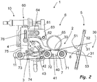
- Fig. 1 and 2 show a perspective view and a side view of a part of a weaving machine 1 having a clamping device 2, respectively.
- the weaving machine 1 comprises a stationary arranged weaving machine frame 10 to which the clamping device 2 is mounted.
- the clamping device 2 is arranged between a woven fabric 3 and a cutting device 4.
- the weaving machine 1 is an air-jet weaving machine.
- a weft thread (not shown) is inserted in a shed 30 formed by selectively raising and lowering warp threads 31.
- the weft thread is guided in an insertion channel 51 of a reed 5.
- the reed 5 comprises several teeth 52, only partly shown in Figs. 1 and 2 .
- the cutting device 4 shown comprises a stationary cutting blade 40 fixed by means of screws 41 to a support bar 11 stationary arranged at the weaving machine frame 10.
- the cutting device 4 further comprises a pivotable arranged cutting blade 42 mounted at a shaft 43 driven by a motor and of which the top is located sufficiently far from the shaft 43 to cut a weft thread near the beat-up line 33 from the weft thread supply.
- the clamping device 2 comprises a first moveable clamping element with a first clamping surface and a second moveable clamping element with a second clamping surface arranged opposite the first clamping surface, wherein the first moveable clamping element and the second moveable clamping element are supported in a way as to allow at least partly a movement in warp direction.
- a roller 6 is provided as first moveable clamping element and a belt 7 supported by three pulleys 71, 72, 73 is provided as second moveable clamping element.
- the peripheral or outer surfaces of the roller 6 and the belt 7 form the first clamping surface and the second clamping surface, respectively.
- the roller 6 is arranged above the belt 7.
- the outer surface of the roller 6 is contacting the belt 7, thereby forming a clamping region for catching and retaining the ends of inserted weft threads.
- the roller 6 is rotatably mounted about a roller axis extending substantially parallel to an insertion direction A.
- the pulleys 71, 72, 73 are rotatably mounted about axes extending substantially parallel to the insertion direction and the roller axis and are arranged in a way that in the contact region the belt 7 is moved in warp direction.
- a force element 60 is provided for loading the roller 6 with a roller loading force that acts substantially in the transversal direction C.
- the roller 6 is mounted to the weaving machine frame 10 by means of an L-shaped bracket 61, wherein the roller 6 is mounted to one leg of the L-shaped bracket 61 and the force element acts on the second leg of the L-shaped bracket 61.
- the L-shaped bracket 61 is pivotably mounted about a pivot axis 62 at a cantilever arm 63.
- the pivot axis 62 runs in parallel to the axis of the roller 6.
- the roller 6 can hereby carry out a transversal movement with respect to the weft direction.
- the cantilever arm 63 is adjustably mounted with respect to the axes of the pulleys 71, 72, 73 in the warp direction. By moving the cantilever arm 63 in the warp direction, a position of the clamping region formed between the roller 6 and the belt 7 with respect to a beat-up line 33 is adjustable.
- the beat-up line is the line formed at the last beaten-up weft thread.
- the cantilever arm 63 is provided with a slot hole 64 and is horizontally displaceable mounted to the weaving machine frame 10 by means of the slot hole 64.
- the roller loading force applied by the force element 60 acts via the roller 6 on the belt 7 and on the weft threads clamped between the roller 6 and the belt 7.
- the force applied by the force element 60 also avoids an unintended lifting of the roller 6 from the belt 7.
- the clamping device 2 is opened by pivoting the bracket 61 with the roller 6 mounted thereon against the roller loading force applied by the force element 60.
- the cutting device 4 is used for opening the clamping device 2, wherein the pivotable arranged cutting blade 42 is coupled to the roller 6 and/or the bracket 61 for lifting the roller 6 against the roller loading force.
- the loading force of the force element 60 can be reversed, so that the bracket 61 is rotated in a direction in which the roller 6 lifts from the belt 7.
- the pulleys 71, 72, 73 are mounted to the support bar 11.
- the roller 6 contacts the belt 7 between a first pulley 71 and a second pulley 72.
- an additional tensioning disc 74 is provided for tensioning the belt 7.
- the additional tensioning disc 74 contacts the belt 7 between the second pulley 72 and the third pulley 73.
- the additional tensioning disc 74 is adjustably mounted with respect to the axes of the pulleys 71, 72, 73 transversally to the warp direction, wherein a belt tension is adjustable using the additional tensioning discs 74.
- the additional tensioning disc 74 is mounted to a holder 75, said holder 75 being provided with a slot hole 76 and mounted by means of the slot hole 76 as to allow a vertical displacement.
- the tensioning disc 74 is held under tension by a holder under spring force, for example a holder formed by a lever.
- the pulley 73 also functions as tensioning disc.
- the pulley 73 is displaceably arranged, so that the belt 7 can be tensioned by displacing the pulley 73.
- Both, the roller 6 and the belt 7 are passively arranged at the weaving machine frame 10, and the clamping surfaces of the roller 6 and the belt 7 are configured to move in contact with the ends of inserted weft threads without relative sliding of the ends of inserted weft threads over the clamping surfaces in the warp direction.
- the roller 6 and the belt 7 are carried along with the moving ends of the clamped weft threads and, thereby, are driven to move with the clamped weft threads in warp direction, wherein along the contact region, a contact with the ends of the weft threads is maintained.
- the roller 6 shown is disc-shaped and is provided with a tire 65 from a rubber or rubber-like material that provides for a high friction coefficient with respect to the weft threads. In other embodiments, a sleeve-shaped roller is provided.
- the inserted weft thread is guided with an associated main nozzle 8 upon entering into the clamping device 2.
- the main nozzle 8 moves with the reed 5 and is arranged in line with an air guide channel 51 of the reed 5, but a few millimeters in front of the beat-up part 53 of the reed 5. Due to the distance between the main nozzle 8 and the beat-up part 53 of the reed 5 in warp direction, the end of the weft thread is forced by the main nozzle 8 into the clamping region to a position past the beat-up line 33. As a result, the clamped weft threads, and hence the roller 6 and the belt 7 driven by the weft threads, make a movement "to and fro" during each beat-up.
- clamping device and the weaving machine according to the invention are not limited to the exemplary embodiments described by way of example and illustrated in the drawings.
- the clamping device and the weaving machine can also be configured within the claims according to variant embodiments, shapes and dimensions. Combinations of the described and illustrated embodiments that come under the claims are also possible.
Description
- The present invention relates to a clamping device for clamping ends of inserted weft threads on a weaving machine. The present invention further relates to a weaving machine having a clamping device.
- On a weaving machine, weft threads are supplied from a weft thread supply. After insertion of a weft thread into a shed, the weft thread is cut off from the weft thread supply by a cutting device. In order to obtain high fabric quality, inserted weft threads are to be retained with a sufficient tension at the insertion side and at the arrival side. In the context of the application, the side of the weaving machine where the weft thread is inserted, is referred to as insertion side. The other side, where the inserted weft thread arrives, is referred to as arrival side.
-
US 4,834,145 relates to a cutting device comprising a weft thread clamp with two jaws arranged next to the cutting device, wherein the cutting device is activated by a drive system that is completely separated from the main weaving machine drive system. At the insertion side, the inserted weft thread is forced between the jaws of the weft thread clamp. Thus, a beat-up of the weft thread causes the weft thread to enter the cutting device and to be brought into and clamped by the weft thread clamp. The weft thread clamp comprises a spring element, wherein a restoration force of the spring element is adjustable for adjusting a clamping force. -
US 4,541,460 discloses a clamping device for catching and retaining the ends of inserted weft threads comprising a disc rotatable about an axis extending substantially parallel to the weft thread insertion direction and a curved stationary clamping surface positioned opposite a portion of the periphery of said disc to define a curved split there between in which the ends of inserted weft threads are received and advanced. The device further comprises drive means for intermittently rotating said disc in order to advance the weft threads retained within said split in the direction of the beating-up motion of a reed. -
JP 10-204758 - It is an object of the invention to provide a clamping device for a weaving machine, wherein the ends of the inserted weft threads are retained under tension. It is further an object of the invention to provide a weaving machine having a clamping device.
- This object is achieved by a clamping device for a weaving machine according to claim 1. The clamping device comprises a first moveable clamping element with a first clamping surface and a second moveable clamping element with a second clamping surface arranged opposite the first clamping surface, the first clamping surface and the second clamping surface form a clamping region there between for catching and retaining the ends of inserted weft threads. The first moveable clamping element and the second moveable clamping element are passively arranged, i.e. no drive units are provided for driving and/or braking the first moveable clamping element and the second moveable clamping element and wherein the first clamping surface and the second clamping surface are configured to be carried along with the ends of inserted weft threads and to move in contact with the ends of inserted weft threads without relative sliding of the ends of inserted weft threads over the clamping surfaces in the warp direction.
- In use, the clamping surfaces are arranged on both the topside and the underside of inserted weft threads, wherein the ends of the inserted weft threads enter the clamping region between the clamping surfaces.
- The moveable clamping elements are passively arranged. In other words, there are no drive units or similar devices associated with the bearings of the moveable clamping elements for actively driving and/or braking the moveable clamping elements. However, the moveable clamping elements are arranged to be passively driven by external means such as the moving weft threads. In the context of the application, this arrangement is referred to as passive arrangement. To the contrary, in accordance with the prior art, drive units are provided for driving the moveable clamping elements, wherein a speed at the clamping surface needs to be adjusted to the transferring speed of the ends of retained weft threads. In case the speed of the moveable clamping element at the clamping surface in the warp direction differs from a transferring speed of the ends of retained weft threads, the ends of the retained weft threads will slide over the clamping surfaces. When a weft thread slides over a clamping surface, a direction of the dynamic friction force is always opposed to the moving direction. In accordance with the application, the moveable clamping elements are passively arranged and the clamping surfaces are configured to be carried along with the moving weft threads, wherein at the clamping surfaces a contact with the ends of the weft threads is maintained. Without any sliding, a static friction force acts between the clamping surface and the weft threads. The static friction force also prevents a movement in the insertion direction of the weft threads, also named weft direction. Even in case the weft threads tend to move in the insertion direction, a dynamic friction force acts against the movement of the weft threads. As a relative movement between the weft threads and the clamping surfaces in the direction of the warp threads is prevented, said dynamic friction force acts in the insertion direction and the force in the insertion direction is not reduced by force components resulting from a sliding effect of the weft threads over the clamping surface in the warp direction. Hence, the weft threads are retained with high tension.
- Further, due to the movement of the clamping surfaces with the ends of the weft threads, there is no effect on the twisting of the clamped ends of the weft threads.
- In addition, due to the movement of the moveable clamping elements, no dust will collect in the clamping device as the dust is removed during the movement of the clamping elements.
- In one embodiment, two rotatably mounted rollers are provided as first and second moveable clamping element, respectively. In other embodiments, two belts are provided as moveable clamping elements.
- In a preferred embodiment, a roller is provided as first moveable clamping element and a belt supported by at least two, preferably three pulleys is provided as second moveable clamping element. The axes of the roller and the pulleys are arranged parallel to one another, and substantially parallel to the insertion direction. By providing a roller and a belt, a length of the clamping region, referred to as clamping length in the following, is increased compared to an embodiment with two rollers. Hence, a large number of weft threads can be retained in the clamping device, and the clamped ends of the weft threads are supported over a long distance. A clamping length depends on various parameters such as a diameter difference of the pulleys, an arrangement of the pulleys and/or a distance between the roller and the belt. In a preferred embodiment, a clamping length of about 10 mm to 15 mm is obtained. Preferably three pulleys and an additional tensioning disc are provided, wherein the roller contacts the belt between a first and a second pulley, and the additional tensioning disc provided for tensioning the belt contacts the belt between the second and a third pulley. Thereby, the tensioning disc does not interfere with the roller of the clamping device. In one embodiment, a belt tension is adjustable using the additional tensioning discs. The roller and the pulleys are rotatably mounted about axes extending substantially parallel to the insertion direction. In preferred embodiments, bearings for the roller and/or the pulleys are configured to ensure that the roller and/or the pulleys will rotate freely, whereby bearing friction forces are avoided or at least reduced. To this end, suitable bearings are provided.
- The roller is preferably positioned above the belt. In this case, the belt functions as guiding surface for the ends of the inserted weft threads. In addition, the arrangement may be advantageous in view of the available mounting space on known weaving machines. The roller and the belt, and thus the clamping region, are positioned in warp direction with respect to the beat-up line, so that the weft thread just beaten-up can be retained by the clamping device.
- A position of a clamping region between the roller and the belt depends on the position of the roller in a warp direction. In preferred embodiments, an axis of the roller is adjustably mounted with respect to the axes of the pulleys in a warp direction. In the context of the application, a mounting in a fixed but adjustable position is referred to as "adjustable mounting". Hence, the roller axis and the roller can be positioned and fixed in a suitable position with respect to the beat-up line. In other words, the position of the clamping region between the roller and the belt can be set or regulated. As a result, the position of the said clamping region can also be set or regulated with respect to the beat-up line. In use, the clamping region is part of or coincides with the contact region.
- In a preferred embodiment, the roller contacts the belt in a contact region between two pulleys. In other words, the roller acts on the belt in a contact region, in which the belt is not supported on the pulleys. In such an arrangement, the roller is further used to tension the belt. In addition, the belt can be arranged so that the belt protrudes beyond the beat-up line, providing a guiding surface for the weft threads towards the clamping region.
- In addition, in preferred embodiments, the roller is mounted in a way as to allow transversal movement with respect to the insertion direction. In one embodiment, the roller is rotatably mounted about a pivot axis that is parallel but offset laterally to the roller axis, for example by means of a pivotable arranged lever. In other embodiments, the roller is slidably mounted. The moveable mounting allows to open the clamping device by lifting the roller, for example in case of a broken weft thread. In a preferred embodiment, an opening of the clamping device is carried out, for example, when an automatic weft thread repair is carried out, as known from
US 4,834,145 . During normal operation, in one embodiment the roller is fixed in a use position, for example by means of a fixing screw. In other embodiments, the roller is held in a use position by a force element. - In one embodiment, a force element is provided for loading the roller with a roller loading force. The roller loading force acts via the roller on the belt and on the weft threads clamped between the roller and the belt. Generally, the larger the roller loading force with which the roller is loaded, the larger the clamping force. As the clamping surfaces move with the weft thread, the ends of the weft threads may easily enter the clamping region, even with high clamping forces being involved. In use, the force element also functions to avoid an unintended lifting of the roller in a transversal direction with respect to the insertion direction. In one embodiment, the roller is mounted by means of a pivotable L-shaped bracket, wherein the roller is mounted to one leg of the L-shaped bracket and a force element acts on the second leg of the bracket.
- In a preferred embodiment, the force element comprises a force regulator for adjusting the roller loading force. Hence, the clamping force can be regulated by the force regulator, for example a pneumatic cylinder. In a preferred embodiment, a pressure regulator that is controlled by a control unit of the weaving machine is provided, wherein the pressure and, therefore, the clamping force can be set via a man-machine-interface of the weaving machine. In another embodiment the force regulator comprises a spring of which the spring force can be set. In still another embodiment the force regulator comprises an actuator, for example an electrical actuator or an actuator based on a fluid.
- The clamping surfaces of the clamping elements are supposed to keep contact with the moving weft threads. Therefore, in preferred embodiments, the clamping surfaces of the clamping elements have a high friction coefficient with respect to the weft threads.
- In one embodiment, the belt is formed from a reinforced rubber or reinforced rubber-like material, in particular a fiber reinforced rubber or fiber reinforced rubber-like material. In addition or as an alternative, the roller is provided with a tire from a rubber or rubber-like material, in particular a reinforced rubber or reinforced rubber-like material. In one embodiment, a para-aramid synthetic fiber, provided under the trademark Kevlar®, is used as reinforcement fiber. The rubber or rubber-like material provides for a high friction coefficient with respect to the weft threads. In addition, due to the elastic properties of the rubber or rubber-like material, the weft threads are clamped under deformation of the belt. Hence, weft threads of different diameters can be clamped successively without adjusting the width of the clamping region. A width of the belt is chosen. In one embodiment, widths of about 2 mm to 5 mm have proved advantageous.
- According to a second aspect a weaving machine, in particular an air-jet weaving machine, comprising at least one clamping device, is provided. The clamping device may be arranged at the insertion side and/or at the arrival side of a weaving machine. As the clamping device allows to clamp the ends of the inserted weft threads under a high tension, the length of the ends extending outside the fabric can be chosen small, for example 6 mm or less.
- The clamping device may be arranged at the insertion side and/or at the arrival side of a weaving machine.
- In a preferred embodiment, the clamping device is arranged at the insertion side. In order to obtain high fabric quality, retaining the weft threads at the insertion side with a clamping device according to the invention is advantageous. At the insertion side, the weft thread is cut off from the weft thread supply while the weft thread is tensioned with a relatively large tension. In other words, the weft thread is "firmly" tensioned between a reed and the weft thread supply, in particular a pin of a prewinder. When cutting off the weft thread, the weft thread is to be clamped with a sufficient clamping force. Also retaining the weft threads at the arrival side with a clamping device according to the invention is advantageous. At the arrival side the catching of a weft thread by the clamping device can be simplified by clamping the weft thread at the arrival side with a thread clamp, for example a thread clamp that moves with the reed, while the weft thread is brought into the clamping device according to the invention.
- In preferred embodiments, the clamping device is arranged so that the weft thread enters the clamping region during beating-up the weft thread, while the weft thread is still tensioned between the weft thread supply, in particular the prewinder, and the reed. Due to the tension in the weft thread, the ends of the weft threads in tensioned state can easily enter into the clamping region of the clamping device.
- In preferred embodiments, a cutting device is provided, which is arranged next to the at least one clamping device. As will be understood, the clamping device and the cutting device are properly aligned to each other.
- Preferably, the weaving machine is an air-jet weaving machine with at least one main nozzle guiding the inserted weft thread upon entering in the clamping device. The at least one main nozzle moves with the reed and blows in insertion direction. The at least one main nozzle is arranged in line with an air guide channel of the reed, but a few millimeters in front of the beat-up part of the reed. Due to the distance between the main nozzle and the beat-up part of the reed in warp direction, the end of the weft thread is forced into the clamping region by the main nozzle to a position past the beat-up line. The woven fabric has at least partly elastic properties and may therefore be elastically deformed during beat-up. As a result, the weft threads that are not yet cut, and hence, the roller and the belt driven by the weft threads, make a movement to and fro during each beat-up. As the clamping elements are not driven by external drive means, this movement is not conflicting with external drive means.
- Further features and advantages of the invention will emerge from the following description of the embodiments schematically illustrated in the drawings, wherein
- Fig. 1
- is a perspective view of a part of a weaving machine having a clamping device;
- Fig. 2
- is a side view of the clamping device of
Fig. 1 . - In the following, embodiments of the invention will be described in detail with reference to the drawings. Throughout the drawings, the same elements will be denoted by the same reference numerals.
-
Fig. 1 and2 show a perspective view and a side view of a part of a weaving machine 1 having aclamping device 2, respectively. - The weaving machine 1 comprises a stationary arranged weaving
machine frame 10 to which theclamping device 2 is mounted. Theclamping device 2 is arranged between awoven fabric 3 and acutting device 4. In the embodiment shown, the weaving machine 1 is an air-jet weaving machine. When weaving, a weft thread (not shown) is inserted in a shed 30 formed by selectively raising and loweringwarp threads 31. During insertion, the weft thread is guided in aninsertion channel 51 of areed 5. Thereed 5 comprisesseveral teeth 52, only partly shown inFigs. 1 and2 . - After the insertion, the inserted weft thread is cut off from a weft thread supply (not shown) by means of the
cutting device 4. Thecutting device 4 shown comprises astationary cutting blade 40 fixed by means ofscrews 41 to asupport bar 11 stationary arranged at the weavingmachine frame 10. Thecutting device 4 further comprises a pivotable arranged cuttingblade 42 mounted at ashaft 43 driven by a motor and of which the top is located sufficiently far from theshaft 43 to cut a weft thread near the beat-upline 33 from the weft thread supply. - The end of the inserted weft thread that protrudes from an edge of the woven
fabric 3 is caught and retained by theclamping device 2. Theclamping device 2 comprises a first moveable clamping element with a first clamping surface and a second moveable clamping element with a second clamping surface arranged opposite the first clamping surface, wherein the first moveable clamping element and the second moveable clamping element are supported in a way as to allow at least partly a movement in warp direction. - In the embodiment shown, a
roller 6 is provided as first moveable clamping element and abelt 7 supported by threepulleys roller 6 and thebelt 7 form the first clamping surface and the second clamping surface, respectively. Theroller 6 is arranged above thebelt 7. The outer surface of theroller 6 is contacting thebelt 7, thereby forming a clamping region for catching and retaining the ends of inserted weft threads. - The
roller 6 is rotatably mounted about a roller axis extending substantially parallel to an insertion direction A. When rotating theroller 6 about the roller axis, in the contact region theroller 6 is moved in the warp direction B. Thepulleys belt 7 is moved in warp direction. - A
force element 60 is provided for loading theroller 6 with a roller loading force that acts substantially in the transversal direction C. Theroller 6 is mounted to the weavingmachine frame 10 by means of an L-shapedbracket 61, wherein theroller 6 is mounted to one leg of the L-shapedbracket 61 and the force element acts on the second leg of the L-shapedbracket 61. The L-shapedbracket 61 is pivotably mounted about apivot axis 62 at acantilever arm 63. Thepivot axis 62 runs in parallel to the axis of theroller 6. Theroller 6 can hereby carry out a transversal movement with respect to the weft direction. Thecantilever arm 63 is adjustably mounted with respect to the axes of thepulleys cantilever arm 63 in the warp direction, a position of the clamping region formed between theroller 6 and thebelt 7 with respect to a beat-upline 33 is adjustable. The beat-up line is the line formed at the last beaten-up weft thread. In the embodiment shown, thecantilever arm 63 is provided with aslot hole 64 and is horizontally displaceable mounted to the weavingmachine frame 10 by means of theslot hole 64. - The roller loading force applied by the
force element 60 acts via theroller 6 on thebelt 7 and on the weft threads clamped between theroller 6 and thebelt 7. The force applied by theforce element 60 also avoids an unintended lifting of theroller 6 from thebelt 7. In case of a broken weft thread, theclamping device 2 is opened by pivoting thebracket 61 with theroller 6 mounted thereon against the roller loading force applied by theforce element 60. In one embodiment, thecutting device 4 is used for opening theclamping device 2, wherein the pivotable arranged cuttingblade 42 is coupled to theroller 6 and/or thebracket 61 for lifting theroller 6 against the roller loading force. In another embodiment the loading force of theforce element 60 can be reversed, so that thebracket 61 is rotated in a direction in which theroller 6 lifts from thebelt 7. - The
pulleys support bar 11. In the embodiment shown, theroller 6 contacts thebelt 7 between afirst pulley 71 and asecond pulley 72. Further, anadditional tensioning disc 74 is provided for tensioning thebelt 7. Theadditional tensioning disc 74 contacts thebelt 7 between thesecond pulley 72 and thethird pulley 73. Theadditional tensioning disc 74 is adjustably mounted with respect to the axes of thepulleys additional tensioning discs 74. In the embodiment shown, theadditional tensioning disc 74 is mounted to aholder 75, saidholder 75 being provided with aslot hole 76 and mounted by means of theslot hole 76 as to allow a vertical displacement. In another embodiment thetensioning disc 74 is held under tension by a holder under spring force, for example a holder formed by a lever. In still another embodiment, thepulley 73 also functions as tensioning disc. In this embodiment, thepulley 73 is displaceably arranged, so that thebelt 7 can be tensioned by displacing thepulley 73. - Both, the
roller 6 and thebelt 7 are passively arranged at the weavingmachine frame 10, and the clamping surfaces of theroller 6 and thebelt 7 are configured to move in contact with the ends of inserted weft threads without relative sliding of the ends of inserted weft threads over the clamping surfaces in the warp direction. Theroller 6 and thebelt 7 are carried along with the moving ends of the clamped weft threads and, thereby, are driven to move with the clamped weft threads in warp direction, wherein along the contact region, a contact with the ends of the weft threads is maintained. - The
roller 6 shown is disc-shaped and is provided with atire 65 from a rubber or rubber-like material that provides for a high friction coefficient with respect to the weft threads. In other embodiments, a sleeve-shaped roller is provided. - The inserted weft thread is guided with an associated main nozzle 8 upon entering into the
clamping device 2. The main nozzle 8 moves with thereed 5 and is arranged in line with anair guide channel 51 of thereed 5, but a few millimeters in front of the beat-uppart 53 of thereed 5. Due to the distance between the main nozzle 8 and the beat-uppart 53 of thereed 5 in warp direction, the end of the weft thread is forced by the main nozzle 8 into the clamping region to a position past the beat-upline 33. As a result, the clamped weft threads, and hence theroller 6 and thebelt 7 driven by the weft threads, make a movement "to and fro" during each beat-up. - The clamping device and the weaving machine according to the invention are not limited to the exemplary embodiments described by way of example and illustrated in the drawings. The clamping device and the weaving machine can also be configured within the claims according to variant embodiments, shapes and dimensions. Combinations of the described and illustrated embodiments that come under the claims are also possible.
Claims (15)
- Clamping device for a weaving machine comprising a first moveable clamping element (6) with a first clamping surface and a second moveable clamping element (7) with a second clamping surface arranged opposite the first clamping surface, the first clamping surface and the second clamping surface forming a clamping region there between for catching and retaining ends of inserted weft threads, characterized in that the first moveable clamping element and the second moveable clamping element are passively arranged, i.e. no drive units are provided for driving and/or braking the first moveable clamping element (6) and the second moveable clamping element (7), and wherein the first clamping surface and the second clamping surface are configured to be carried along with the ends of inserted weft threads and to move in contact with the ends of inserted weft threads without relative sliding of the ends of inserted weft threads over the clamping surfaces in the warp direction.
- Clamping device according to claim 1, wherein a roller (6) is provided as first moveable clamping element and a belt (7) supported by at least two, preferably three pulleys (71, 72, 73) is provided as second moveable clamping element.
- Clamping device according to claim 2, wherein the roller (6) is arranged above the belt (7).
- Clamping device according to any one of claims 2 or 3, wherein an axis of the roller (6) is adjustably mounted with respect to the axes of the pulleys (71, 72, 73) in a warp direction.
- Clamping device according to any one of claims 2 to 4, wherein the roller (6) contacts the belt (7) in a contact region between two pulleys (71, 72).
- Clamping device according to any one of claims 2 to 5, wherein the roller (6) is mounted in a way as to allow transversal movement with respect to the insertion direction.
- Clamping device according to any one of claims 2 to 6, wherein a force element (60) is provided for loading the roller (6) with a roller loading force.
- Clamping device according to claim 7, wherein the force element (60) comprises a force regulator for adjusting the roller loading force.
- Clamping device according to any one of claims 1 to 8, wherein the clamping surfaces of the clamping elements have a high friction coefficient with respect to the weft threads.
- Clamping device according to any one of claims 2 to 9, wherein the belt (7) is formed from a reinforced rubber or reinforced rubber-like material, in particular a fiber reinforced rubber or fiber reinforced rubber-like material.
- Clamping device according to any one of claims 2 to 10, wherein the roller (6) is provided with a tire (60) from a rubber or rubber-like material, in particular a reinforced rubber or reinforced rubber-like material.
- Weaving machine comprising at least one clamping device (2) according to any one of claims 1 to 11.
- Weaving machine according to claim 12, wherein at least one clamping device (2) is arranged at the insertion side.
- Weaving machine according to claim 13, wherein a cutting device (4) is provided, which is arranged next to the at least one clamping device (2).
- Weaving machine according to any one of claims 12 to 14, wherein the weaving machine (1) is an air-jet weaving machine with at least one main nozzle (8) guiding the inserted weft thread upon entering into the clamping device (2).
Applications Claiming Priority (2)
| Application Number | Priority Date | Filing Date | Title |
|---|---|---|---|
| BE2012/0776A BE1021513B1 (en) | 2012-11-19 | 2012-11-19 | CLIPPING DEVICE AND WEAVING MACHINE WITH A CLIPPING DEVICE |
| PCT/EP2013/072501 WO2014075904A1 (en) | 2012-11-19 | 2013-10-28 | Clamping device and weaving machine with a clamping device |
Publications (2)
| Publication Number | Publication Date |
|---|---|
| EP2920345A1 EP2920345A1 (en) | 2015-09-23 |
| EP2920345B1 true EP2920345B1 (en) | 2019-02-27 |
Family
ID=47630013
Family Applications (1)
| Application Number | Title | Priority Date | Filing Date |
|---|---|---|---|
| EP13783564.1A Not-in-force EP2920345B1 (en) | 2012-11-19 | 2013-10-28 | Clamping device and weaving machine with a clamping device |
Country Status (3)
| Country | Link |
|---|---|
| EP (1) | EP2920345B1 (en) |
| BE (1) | BE1021513B1 (en) |
| WO (1) | WO2014075904A1 (en) |
Family Cites Families (3)
| Publication number | Priority date | Publication date | Assignee | Title |
|---|---|---|---|---|
| CH106527A (en) * | 1923-12-13 | 1924-09-01 | Strohmeier Ernst | Thread cutting device on looms with gunshot apparatus. |
| DE59305157D1 (en) * | 1993-05-21 | 1997-02-27 | Rueti Ag Maschf | Cutting device for weft threads and weaving machine with such a device |
| JPH10204758A (en) * | 1997-01-16 | 1998-08-04 | Tsudakoma Corp | Controller of weft holder in loom |
-
2012
- 2012-11-19 BE BE2012/0776A patent/BE1021513B1/en not_active IP Right Cessation
-
2013
- 2013-10-28 EP EP13783564.1A patent/EP2920345B1/en not_active Not-in-force
- 2013-10-28 WO PCT/EP2013/072501 patent/WO2014075904A1/en active Application Filing
Non-Patent Citations (1)
| Title |
|---|
| None * |
Also Published As
| Publication number | Publication date |
|---|---|
| BE1021513B1 (en) | 2015-12-04 |
| EP2920345A1 (en) | 2015-09-23 |
| WO2014075904A1 (en) | 2014-05-22 |
Similar Documents
| Publication | Publication Date | Title |
|---|---|---|
| CN105765122B (en) | For the device of cutting weft yarn in loom weaving process and the loom with this device | |
| US20090065089A1 (en) | Cutting Apparatus For A Weaving Machine And Method For The Operation Of The Same | |
| EP2812472B1 (en) | Device for catching and stretching a weft thread, weaving machine and method for catching and stretching a weft thread | |
| EP2920345B1 (en) | Clamping device and weaving machine with a clamping device | |
| EP2122027B1 (en) | Gripper weaving machine, bringer gripper and deflecting guide | |
| RU2501893C2 (en) | Head of rapier for weaving machine | |
| KR890004812B1 (en) | Adjustabile apparatus for sewing machine thread tensioning device | |
| JP5185682B2 (en) | Method and apparatus for producing flat yarn fabric | |
| US6155309A (en) | Settable weft clamping and severing apparatus | |
| CN216141687U (en) | Damping adjusting device and yarn ironing and shaping device | |
| EP1021603B1 (en) | Device for cutting the weft yarn in air weaving looms | |
| US3951179A (en) | Device for severing a thread in a textile machine | |
| EP2349896B1 (en) | Thread brake and method of using the thread brake | |
| CN109415849B (en) | Device for clamping weft threads | |
| US4781222A (en) | Fabric winding device for weaving looms | |
| TWI765116B (en) | Weft insertion device of rapier loom | |
| US3797279A (en) | Thread-feeding, tension-regulating device for straight knitting machines | |
| JPH10130999A (en) | Weft-clamping and stretching apparatus of fluid-jet loom | |
| GB2041418A (en) | Weft supply shuttleless looms | |
| CN220467001U (en) | Guiding mechanism is used in textile fabric production and processing | |
| EP3988488A1 (en) | Yarn winder | |
| BE1020142A3 (en) | THREAD CLAMP FOR A WEIGHT THREAD AT A WEAVING MACHINE. | |
| US4660372A (en) | Driving arrangement for open-end friction spinning machines | |
| KR20100008926A (en) | Tensioning device for knitting machine | |
| KR102099611B1 (en) | Remnants fabric cutting apparatus for wet tissue |
Legal Events
| Date | Code | Title | Description |
|---|---|---|---|
| PUAI | Public reference made under article 153(3) epc to a published international application that has entered the european phase |
Free format text: ORIGINAL CODE: 0009012 |
|
| 17P | Request for examination filed |
Effective date: 20150401 |
|
| AK | Designated contracting states |
Kind code of ref document: A1 Designated state(s): AL AT BE BG CH CY CZ DE DK EE ES FI FR GB GR HR HU IE IS IT LI LT LU LV MC MK MT NL NO PL PT RO RS SE SI SK SM TR |
|
| AX | Request for extension of the european patent |
Extension state: BA ME |
|
| DAX | Request for extension of the european patent (deleted) | ||
| GRAP | Despatch of communication of intention to grant a patent |
Free format text: ORIGINAL CODE: EPIDOSNIGR1 |
|
| STAA | Information on the status of an ep patent application or granted ep patent |
Free format text: STATUS: GRANT OF PATENT IS INTENDED |
|
| INTG | Intention to grant announced |
Effective date: 20180925 |
|
| GRAS | Grant fee paid |
Free format text: ORIGINAL CODE: EPIDOSNIGR3 |
|
| GRAA | (expected) grant |
Free format text: ORIGINAL CODE: 0009210 |
|
| STAA | Information on the status of an ep patent application or granted ep patent |
Free format text: STATUS: THE PATENT HAS BEEN GRANTED |
|
| AK | Designated contracting states |
Kind code of ref document: B1 Designated state(s): AL AT BE BG CH CY CZ DE DK EE ES FI FR GB GR HR HU IE IS IT LI LT LU LV MC MK MT NL NO PL PT RO RS SE SI SK SM TR |
|
| REG | Reference to a national code |
Ref country code: GB Ref legal event code: FG4D |
|
| REG | Reference to a national code |
Ref country code: CH Ref legal event code: EP |
|
| REG | Reference to a national code |
Ref country code: AT Ref legal event code: REF Ref document number: 1101475 Country of ref document: AT Kind code of ref document: T Effective date: 20190315 |
|
| REG | Reference to a national code |
Ref country code: IE Ref legal event code: FG4D |
|
| REG | Reference to a national code |
Ref country code: DE Ref legal event code: R096 Ref document number: 602013051483 Country of ref document: DE |
|
| REG | Reference to a national code |
Ref country code: NL Ref legal event code: MP Effective date: 20190227 |
|
| REG | Reference to a national code |
Ref country code: LT Ref legal event code: MG4D |
|
| PG25 | Lapsed in a contracting state [announced via postgrant information from national office to epo] |
Ref country code: PT Free format text: LAPSE BECAUSE OF FAILURE TO SUBMIT A TRANSLATION OF THE DESCRIPTION OR TO PAY THE FEE WITHIN THE PRESCRIBED TIME-LIMIT Effective date: 20190627 Ref country code: SE Free format text: LAPSE BECAUSE OF FAILURE TO SUBMIT A TRANSLATION OF THE DESCRIPTION OR TO PAY THE FEE WITHIN THE PRESCRIBED TIME-LIMIT Effective date: 20190227 Ref country code: NO Free format text: LAPSE BECAUSE OF FAILURE TO SUBMIT A TRANSLATION OF THE DESCRIPTION OR TO PAY THE FEE WITHIN THE PRESCRIBED TIME-LIMIT Effective date: 20190527 Ref country code: FI Free format text: LAPSE BECAUSE OF FAILURE TO SUBMIT A TRANSLATION OF THE DESCRIPTION OR TO PAY THE FEE WITHIN THE PRESCRIBED TIME-LIMIT Effective date: 20190227 Ref country code: NL Free format text: LAPSE BECAUSE OF FAILURE TO SUBMIT A TRANSLATION OF THE DESCRIPTION OR TO PAY THE FEE WITHIN THE PRESCRIBED TIME-LIMIT Effective date: 20190227 Ref country code: LT Free format text: LAPSE BECAUSE OF FAILURE TO SUBMIT A TRANSLATION OF THE DESCRIPTION OR TO PAY THE FEE WITHIN THE PRESCRIBED TIME-LIMIT Effective date: 20190227 |
|
| PG25 | Lapsed in a contracting state [announced via postgrant information from national office to epo] |
Ref country code: BG Free format text: LAPSE BECAUSE OF FAILURE TO SUBMIT A TRANSLATION OF THE DESCRIPTION OR TO PAY THE FEE WITHIN THE PRESCRIBED TIME-LIMIT Effective date: 20190527 Ref country code: GR Free format text: LAPSE BECAUSE OF FAILURE TO SUBMIT A TRANSLATION OF THE DESCRIPTION OR TO PAY THE FEE WITHIN THE PRESCRIBED TIME-LIMIT Effective date: 20190528 Ref country code: IS Free format text: LAPSE BECAUSE OF FAILURE TO SUBMIT A TRANSLATION OF THE DESCRIPTION OR TO PAY THE FEE WITHIN THE PRESCRIBED TIME-LIMIT Effective date: 20190627 Ref country code: HR Free format text: LAPSE BECAUSE OF FAILURE TO SUBMIT A TRANSLATION OF THE DESCRIPTION OR TO PAY THE FEE WITHIN THE PRESCRIBED TIME-LIMIT Effective date: 20190227 Ref country code: LV Free format text: LAPSE BECAUSE OF FAILURE TO SUBMIT A TRANSLATION OF THE DESCRIPTION OR TO PAY THE FEE WITHIN THE PRESCRIBED TIME-LIMIT Effective date: 20190227 Ref country code: RS Free format text: LAPSE BECAUSE OF FAILURE TO SUBMIT A TRANSLATION OF THE DESCRIPTION OR TO PAY THE FEE WITHIN THE PRESCRIBED TIME-LIMIT Effective date: 20190227 |
|
| REG | Reference to a national code |
Ref country code: AT Ref legal event code: MK05 Ref document number: 1101475 Country of ref document: AT Kind code of ref document: T Effective date: 20190227 |
|
| PG25 | Lapsed in a contracting state [announced via postgrant information from national office to epo] |
Ref country code: IT Free format text: LAPSE BECAUSE OF FAILURE TO SUBMIT A TRANSLATION OF THE DESCRIPTION OR TO PAY THE FEE WITHIN THE PRESCRIBED TIME-LIMIT Effective date: 20190227 Ref country code: RO Free format text: LAPSE BECAUSE OF FAILURE TO SUBMIT A TRANSLATION OF THE DESCRIPTION OR TO PAY THE FEE WITHIN THE PRESCRIBED TIME-LIMIT Effective date: 20190227 Ref country code: ES Free format text: LAPSE BECAUSE OF FAILURE TO SUBMIT A TRANSLATION OF THE DESCRIPTION OR TO PAY THE FEE WITHIN THE PRESCRIBED TIME-LIMIT Effective date: 20190227 Ref country code: CZ Free format text: LAPSE BECAUSE OF FAILURE TO SUBMIT A TRANSLATION OF THE DESCRIPTION OR TO PAY THE FEE WITHIN THE PRESCRIBED TIME-LIMIT Effective date: 20190227 Ref country code: DK Free format text: LAPSE BECAUSE OF FAILURE TO SUBMIT A TRANSLATION OF THE DESCRIPTION OR TO PAY THE FEE WITHIN THE PRESCRIBED TIME-LIMIT Effective date: 20190227 Ref country code: EE Free format text: LAPSE BECAUSE OF FAILURE TO SUBMIT A TRANSLATION OF THE DESCRIPTION OR TO PAY THE FEE WITHIN THE PRESCRIBED TIME-LIMIT Effective date: 20190227 Ref country code: SK Free format text: LAPSE BECAUSE OF FAILURE TO SUBMIT A TRANSLATION OF THE DESCRIPTION OR TO PAY THE FEE WITHIN THE PRESCRIBED TIME-LIMIT Effective date: 20190227 Ref country code: AL Free format text: LAPSE BECAUSE OF FAILURE TO SUBMIT A TRANSLATION OF THE DESCRIPTION OR TO PAY THE FEE WITHIN THE PRESCRIBED TIME-LIMIT Effective date: 20190227 |
|
| REG | Reference to a national code |
Ref country code: DE Ref legal event code: R097 Ref document number: 602013051483 Country of ref document: DE |
|
| PG25 | Lapsed in a contracting state [announced via postgrant information from national office to epo] |
Ref country code: PL Free format text: LAPSE BECAUSE OF FAILURE TO SUBMIT A TRANSLATION OF THE DESCRIPTION OR TO PAY THE FEE WITHIN THE PRESCRIBED TIME-LIMIT Effective date: 20190227 Ref country code: SM Free format text: LAPSE BECAUSE OF FAILURE TO SUBMIT A TRANSLATION OF THE DESCRIPTION OR TO PAY THE FEE WITHIN THE PRESCRIBED TIME-LIMIT Effective date: 20190227 |
|
| PGFP | Annual fee paid to national office [announced via postgrant information from national office to epo] |
Ref country code: BE Payment date: 20190917 Year of fee payment: 7 |
|
| PG25 | Lapsed in a contracting state [announced via postgrant information from national office to epo] |
Ref country code: AT Free format text: LAPSE BECAUSE OF FAILURE TO SUBMIT A TRANSLATION OF THE DESCRIPTION OR TO PAY THE FEE WITHIN THE PRESCRIBED TIME-LIMIT Effective date: 20190227 |
|
| PLBE | No opposition filed within time limit |
Free format text: ORIGINAL CODE: 0009261 |
|
| STAA | Information on the status of an ep patent application or granted ep patent |
Free format text: STATUS: NO OPPOSITION FILED WITHIN TIME LIMIT |
|
| PGFP | Annual fee paid to national office [announced via postgrant information from national office to epo] |
Ref country code: DE Payment date: 20191023 Year of fee payment: 7 |
|
| 26N | No opposition filed |
Effective date: 20191128 |
|
| PG25 | Lapsed in a contracting state [announced via postgrant information from national office to epo] |
Ref country code: SI Free format text: LAPSE BECAUSE OF FAILURE TO SUBMIT A TRANSLATION OF THE DESCRIPTION OR TO PAY THE FEE WITHIN THE PRESCRIBED TIME-LIMIT Effective date: 20190227 |
|
| PG25 | Lapsed in a contracting state [announced via postgrant information from national office to epo] |
Ref country code: TR Free format text: LAPSE BECAUSE OF FAILURE TO SUBMIT A TRANSLATION OF THE DESCRIPTION OR TO PAY THE FEE WITHIN THE PRESCRIBED TIME-LIMIT Effective date: 20190227 |
|
| PG25 | Lapsed in a contracting state [announced via postgrant information from national office to epo] |
Ref country code: MC Free format text: LAPSE BECAUSE OF FAILURE TO SUBMIT A TRANSLATION OF THE DESCRIPTION OR TO PAY THE FEE WITHIN THE PRESCRIBED TIME-LIMIT Effective date: 20190227 |
|
| REG | Reference to a national code |
Ref country code: CH Ref legal event code: PL |
|
| PG25 | Lapsed in a contracting state [announced via postgrant information from national office to epo] |
Ref country code: CH Free format text: LAPSE BECAUSE OF NON-PAYMENT OF DUE FEES Effective date: 20191031 Ref country code: LI Free format text: LAPSE BECAUSE OF NON-PAYMENT OF DUE FEES Effective date: 20191031 Ref country code: LU Free format text: LAPSE BECAUSE OF NON-PAYMENT OF DUE FEES Effective date: 20191028 |
|
| GBPC | Gb: european patent ceased through non-payment of renewal fee |
Effective date: 20191028 |
|
| PG25 | Lapsed in a contracting state [announced via postgrant information from national office to epo] |
Ref country code: FR Free format text: LAPSE BECAUSE OF NON-PAYMENT OF DUE FEES Effective date: 20191031 Ref country code: GB Free format text: LAPSE BECAUSE OF NON-PAYMENT OF DUE FEES Effective date: 20191028 Ref country code: IE Free format text: LAPSE BECAUSE OF NON-PAYMENT OF DUE FEES Effective date: 20191028 |
|
| REG | Reference to a national code |
Ref country code: DE Ref legal event code: R119 Ref document number: 602013051483 Country of ref document: DE |
|
| PG25 | Lapsed in a contracting state [announced via postgrant information from national office to epo] |
Ref country code: CY Free format text: LAPSE BECAUSE OF FAILURE TO SUBMIT A TRANSLATION OF THE DESCRIPTION OR TO PAY THE FEE WITHIN THE PRESCRIBED TIME-LIMIT Effective date: 20190227 |
|
| REG | Reference to a national code |
Ref country code: BE Ref legal event code: MM Effective date: 20201031 |
|
| PG25 | Lapsed in a contracting state [announced via postgrant information from national office to epo] |
Ref country code: DE Free format text: LAPSE BECAUSE OF NON-PAYMENT OF DUE FEES Effective date: 20210501 Ref country code: HU Free format text: LAPSE BECAUSE OF FAILURE TO SUBMIT A TRANSLATION OF THE DESCRIPTION OR TO PAY THE FEE WITHIN THE PRESCRIBED TIME-LIMIT; INVALID AB INITIO Effective date: 20131028 Ref country code: MT Free format text: LAPSE BECAUSE OF FAILURE TO SUBMIT A TRANSLATION OF THE DESCRIPTION OR TO PAY THE FEE WITHIN THE PRESCRIBED TIME-LIMIT Effective date: 20190227 |
|
| PG25 | Lapsed in a contracting state [announced via postgrant information from national office to epo] |
Ref country code: BE Free format text: LAPSE BECAUSE OF NON-PAYMENT OF DUE FEES Effective date: 20201031 |
|
| PG25 | Lapsed in a contracting state [announced via postgrant information from national office to epo] |
Ref country code: MK Free format text: LAPSE BECAUSE OF FAILURE TO SUBMIT A TRANSLATION OF THE DESCRIPTION OR TO PAY THE FEE WITHIN THE PRESCRIBED TIME-LIMIT Effective date: 20190227 |