EP2919973B1 - Method of manufacturing an optical lens - Google Patents
Method of manufacturing an optical lens Download PDFInfo
- Publication number
- EP2919973B1 EP2919973B1 EP13795699.1A EP13795699A EP2919973B1 EP 2919973 B1 EP2919973 B1 EP 2919973B1 EP 13795699 A EP13795699 A EP 13795699A EP 2919973 B1 EP2919973 B1 EP 2919973B1
- Authority
- EP
- European Patent Office
- Prior art keywords
- during
- lens
- markings
- positioning error
- optical lens
- Prior art date
- Legal status (The legal status is an assumption and is not a legal conclusion. Google has not performed a legal analysis and makes no representation as to the accuracy of the status listed.)
- Active
Links
- 230000003287 optical effect Effects 0.000 title claims description 104
- 238000004519 manufacturing process Methods 0.000 title claims description 61
- 238000000034 method Methods 0.000 claims description 46
- 238000003754 machining Methods 0.000 claims description 23
- 230000000903 blocking effect Effects 0.000 claims description 12
- 238000004590 computer program Methods 0.000 claims description 6
- 230000001276 controlling effect Effects 0.000 description 8
- 230000015654 memory Effects 0.000 description 6
- 230000000875 corresponding effect Effects 0.000 description 5
- 230000006870 function Effects 0.000 description 4
- 230000004438 eyesight Effects 0.000 description 3
- 230000000750 progressive effect Effects 0.000 description 3
- 238000003860 storage Methods 0.000 description 3
- 238000005259 measurement Methods 0.000 description 2
- 201000009310 astigmatism Diseases 0.000 description 1
- 230000005540 biological transmission Effects 0.000 description 1
- 230000002596 correlated effect Effects 0.000 description 1
- 230000002354 daily effect Effects 0.000 description 1
- 230000003203 everyday effect Effects 0.000 description 1
- 230000004048 modification Effects 0.000 description 1
- 238000012986 modification Methods 0.000 description 1
- 238000005457 optimization Methods 0.000 description 1
- 230000004382 visual function Effects 0.000 description 1
Images

Classifications
-
- G—PHYSICS
- G02—OPTICS
- G02C—SPECTACLES; SUNGLASSES OR GOGGLES INSOFAR AS THEY HAVE THE SAME FEATURES AS SPECTACLES; CONTACT LENSES
- G02C13/00—Assembling; Repairing; Cleaning
- G02C13/001—Assembling; Repairing
-
- B—PERFORMING OPERATIONS; TRANSPORTING
- B29—WORKING OF PLASTICS; WORKING OF SUBSTANCES IN A PLASTIC STATE IN GENERAL
- B29D—PRODUCING PARTICULAR ARTICLES FROM PLASTICS OR FROM SUBSTANCES IN A PLASTIC STATE
- B29D11/00—Producing optical elements, e.g. lenses or prisms
- B29D11/00932—Combined cutting and grinding thereof
- B29D11/00942—Combined cutting and grinding thereof where the lens material is mounted in a support for mounting onto a cutting device, e.g. a lathe, and where the support is of machinable material, e.g. plastics
-
- B—PERFORMING OPERATIONS; TRANSPORTING
- B29—WORKING OF PLASTICS; WORKING OF SUBSTANCES IN A PLASTIC STATE IN GENERAL
- B29D—PRODUCING PARTICULAR ARTICLES FROM PLASTICS OR FROM SUBSTANCES IN A PLASTIC STATE
- B29D11/00—Producing optical elements, e.g. lenses or prisms
- B29D11/00951—Measuring, controlling or regulating
-
- G—PHYSICS
- G05—CONTROLLING; REGULATING
- G05B—CONTROL OR REGULATING SYSTEMS IN GENERAL; FUNCTIONAL ELEMENTS OF SUCH SYSTEMS; MONITORING OR TESTING ARRANGEMENTS FOR SUCH SYSTEMS OR ELEMENTS
- G05B19/00—Programme-control systems
- G05B19/02—Programme-control systems electric
- G05B19/18—Numerical control [NC], i.e. automatically operating machines, in particular machine tools, e.g. in a manufacturing environment, so as to execute positioning, movement or co-ordinated operations by means of programme data in numerical form
- G05B19/182—Numerical control [NC], i.e. automatically operating machines, in particular machine tools, e.g. in a manufacturing environment, so as to execute positioning, movement or co-ordinated operations by means of programme data in numerical form characterised by the machine tool function, e.g. thread cutting, cam making, tool direction control
-
- G—PHYSICS
- G05—CONTROLLING; REGULATING
- G05B—CONTROL OR REGULATING SYSTEMS IN GENERAL; FUNCTIONAL ELEMENTS OF SUCH SYSTEMS; MONITORING OR TESTING ARRANGEMENTS FOR SUCH SYSTEMS OR ELEMENTS
- G05B2219/00—Program-control systems
- G05B2219/30—Nc systems
- G05B2219/45—Nc applications
- G05B2219/45157—Grind optical lens
Definitions
- the invention relates to a method of manufacturing an optical lens and a method for controlling a lens manufacturing method.
- An optical lens is typically made of plastic material and generally has two opposing surfaces which co-operate with one another to provide a required refractive property, generally corresponding to the wearer's prescription. When the positioning or shape of one of these surfaces with respect to the other is inaccurate, the required refractive property may not be respected.
- Manufacturing of an optical lens to the required refractive property typically includes machining the surface of a semi-finished lens or lens blank.
- a semi-finished lens has a finished surface, for example the front surface and an unfinished surface, for example the back surface.
- the semi-finished lens is securely maintained in an accurate position on a blocker during the various manufacturing operations in order to prevent the generation of optical errors.
- a semi-finished lens is provided with engraved markings on the finished surface.
- the engraved markings define a reference system of the design of the finished surface of the lens.
- WO 94/06598 A1 discloses a method according to the preamble of claim 1.
- the invention proposes a method of manufacturing an optical lens, the method comprising:
- the second markings being determined according to the refractive properties of the optical lens and the observation condition, checking the accuracy of the relative position of the first and second surfaces in the observation condition may be rendered straight forward.
- the invention also relates to a method for controlling a lens manufacturing method comprising:
- the invention further relates to a method for controlling a lens manufacturing method comprising:
- the invention relates to a computer program product comprising one or more stored sequences of instructions that are accessible to a processor and which, when executed by the processor, causes the processor to carry out the steps of the method according to the invention.
- the invention further relates to a computer readable medium carrying one or more sequences of instructions of the computer program product according to the invention.
- the invention relates to a program which makes a computer execute the method of the invention.
- the invention also relates to a computer-readable storage medium having a program recorded thereon; where the program makes the computer execute the method of the invention.
- the invention further relates to a device comprising a processor adapted to store one or more sequence of instructions and to carry out at least one of the steps of the method according to the invention.
- Such a computer program may be stored in a computer readable storage medium, such as, but is not limited to, any type of disk including floppy disks, optical disks, CD-ROMs, magnetic-optical disks, read-only memories (ROMs), random access memories (RAMs) electrically programmable read-only memories (EPROMs), electrically erasable and programmable read only memories (EEPROMs), magnetic or optical cards, or any other type of media suitable for storing electronic instructions, and capable of being coupled to a computer system bus.
- a computer readable storage medium such as, but is not limited to, any type of disk including floppy disks, optical disks, CD-ROMs, magnetic-optical disks, read-only memories (ROMs), random access memories (RAMs) electrically programmable read-only memories (EPROMs), electrically erasable and programmable read only memories (EEPROMs), magnetic or optical cards, or any other type of media suitable for storing electronic instructions, and capable of being coupled to a computer system bus.
- a "Design” is a widely used wording known from the man skilled in the art to designate the set of parameters allowing defining an optical function of a generic optical system; each ophthalmic lens manufacturer has its own designs, particularly for aspherical lens and for progressive lens.
- a progressive lens "design” results of an optimization of the progressive surface so as to restore a presbyope's ability to see clearly at all distances but also to optimally respect all physiological visual functions such as foveal vision, extra-foveal vision, binocular vision and to minimize unwanted astigmatisms.
- manufacturing parameters are the setting parameters of the different manufacturing devices involved in the manufacturing method.
- method parameter includes any measurable parameters on the manufacturing devices used for the manufacturing of the lens.
- the method of manufacturing an optical lens according to the invention comprises at least:
- a lens member as represented on figure 2A is provided.
- the lens member 10 has a first surface with a first design, for example a preformed front surface 11.
- a first design for example a preformed front surface 11.
- the preformed front surface 11 is disposed nearest the object being viewed and a second surface 12 to be modified by the manufacturing process to provide for example the back surface 13 of the finished optical lens, represented by the dotted line.
- Second surface 12 is machined by a machining tool so that the back surface 13 is orientated with respect to and distanced from the front surface 11, according to the required optical prescription.
- first surface is the front surface of the lens member and the second surface is the back surface
- first surface may be the back surface of the semi-finished lens member and the second surface may be the front surface
- the back surface of the optical lens is formed by the machining process, it will be understood, that in alternative embodiments of the invention both or either surfaces of the lens may be formed by the machining process.
- first markings 111 are provided on the first surface 11 of lens member 10 as reference features for defining a first reference system for positioning of the first design of the first surface 11.
- the markings 111 may be engraved marking have a depth of a few micrometers so as to limit the risk of disturbing the wearer of the resulting finished optical lens.
- the markings 111 may be temporary markings that may be removed before providing the manufactured optical lens to the wearer.
- surface data corresponding to a second surface of the optical lens to be manufactured are provided.
- the surface data correspond to the surface to be manufactured on the second surface 12 and the position of the second surface relative to the first surface so that the optical lens combining the manufactured back surface 13 and the front surface provides the required optical function.
- the surface data can be determined according to the front preformed surface and the wearer's prescription.
- the lens member blocking step S3 the lens member 10 is blocked in a machining position.
- the machining step S4 the second surface of the optical lens is machined according to the surface data such that the desired optical properties of the optical lens are respected.
- the method may comprise prior to the lens member blocking step S3 a lens blocker providing step.
- a lens blocking device for blocking lens member 10 in the correct position for manufacturing processes comprises an insert 21 and a blocking ring 22.
- Blocking cast material 24 is poured into the cavity defined by the lower surface of the lens member 10, the insert 21 and the blocking ring 22.
- the blocking cast material 24 cools to solidify in order to provide a blocker for the lens member 10 at the desired positioning for machining.
- the blocker comprises the machining reference frame in which the machining data are expressed.
- second markings identifying a second reference system of the second surface are determined.
- the second markings are provided on the second surface of the optical lens during the second markings providing step S6.
- the second markings are determined at least according to optical data and observation data.
- the optical data represent the refractive properties of the optical lens.
- the optical data represent the prescription of the wearer.
- the optical data may represent the design of the first and second surfaces, the position of the second relative to the first surface, for example, the thickness and prism of the optical lens and the optical index.
- the observation data represent observation conditions in which the first and second markings are to be observed.
- the observation conditions may be defined by considering the observation device and the position of the manufactured lens in the observation device.
- the position of the manufactured optical lens in the observation device may be defined as the position of an optical lens reference frame and an observation device reference frame.
- the optical lens reference frame can be defined using the blocker if the lens has been maintained on the blocker, or by the normal to one of the surfaces of the optical lens passing through the prism reference point as defined by a harmonized standard ISO 8980.
- determining the relative positions of the two surfaces is rendered much easier, in particular when the observation of the first and second markings is realized in the observation conditions.
- the second markings are determined so as to appear at the same position as the first markings in the observation conditions when the second surface is correctly positioned relatively to the first surface. Therefore, in the observation condition the second and first markings appear superimposed when the second surface is correctly positioned relatively to the first surface.
- the second markings may be determined so as to take into account a positioning error tolerance.
- the second markings 112 may have circular shapes and be determined so as to appear centered over the first markings 111 in the observing conditions when the second surface is correctly positioned relatively to the first surface.
- the radius of the circular shaped second markings may be determined based on an error position tolerance.
- the first markings appear outside the second markings, as illustrated on figure 4B .
- the first markings appear inside the second markings, as illustrated on figure 4C .
- the second markings providing step is realized with the same machining device as the machining step and the optical lens is maintained in same position.
- having the optical lens maintained in the same position during the machining and second markings providing steps guaranties that no positioning error is introduced between the second markings and the second surface.
- the method may further comprise after the second marking providing step:
- these additional steps allow determining the relative position of the first and second surface of the machined optical lens.
- the positions of the first and second markings are determined in the observation conditions corresponding to the observation data.
- the first and second reference systems can be determined based on the positions of the first and second markings.
- the positioning error between the first and second surfaces is determined by comparing the positions of the first and second reference systems during the comparison step S8.
- the positions of the first and second reference systems are compared in a common reference system, for example in the manufactured optical lens reference frame.
- the optical lens reference frame can be defined using the blocker if the lens has been maintained on the blocker, or by the normal to one of the surfaces of the optical lens passing between the reference-markings that have been made mandatory by a harmonized standard ISO 8980.
- the relative position between the first and second markings is determined in the observation condition by an operator.
- the observation condition may consist in placing the optical lens at a predetermined distance of a light source and of the operator's eye.
- the second markings may be determined so as to appear to the operator superimposed with the first marking when the second surface is correctly positioned relative to the first surface or as illustrated on figure 4a to 4C with an error tolerance.
- the operator may very easily check the relative position of the first and second surfaces.
- the observation condition could also be having an image of a light source be projected on to a screen through the machined optical lens. The operator could then observe the markings on the projection screen.
- the method according to the invention may also comprise a sorting step S9, during which the manufactured optical lens is accepted if the positioning error between the first and second surfaces is smaller than or equal to a threshold value and is set aside if the positioning error between the first and second surfaces is greater than said threshold value.
- the threshold value may depend on the prescription of the wearer and/or the design of one or both surfaces and/or the curvature variations of one or both of the surfaces.
- the invention also relates to a method for controlling a lens manufacturing process.
- the method for controlling a lens manufacturing process comprises the steps of:
- the evolution of at least one parameter of the manufacturing device used during the lens manufacturing process is checked over time and the evolution over time of the positioning error of the first and second surfaces of the optical lens is related with the evolution over time of the at least one parameter of the manufacturing device.
- the method according to the invention allows controlling certain method or device parameters of the machining process.
- the position error can be correlated to some of the machining device parameters, thus controlling the evolution over time of the positioning error can help identify a drift or shift of a machining device parameter.
- the optical lenses manufactured when repeating step a) may be different optical lenses from one repetition to the other.
- the optical lens manufactured during step a) may be a master lens.
- the master lens has a different geometrical and/or optical parameter and/or is made of a different material than the lenses to be manufactured during the manufacturing process.
- the choice of the master lens can be done so as to simplify the observation conditions, for example the master lens may comprise two plane and parallel surfaces.
- the choice of the master lens can be done so as to amplify the sensibility of certain parameter to the process parameters.
- the master lens is made of a material and has a design such as its optical parameters are more sensible to a modification of the process parameter that the usual manufactured lenses.
- the use of a master lens makes the correlation between a shift in the positioning error and a parameter of the manufacturing device used during the lens manufacturing process easier and more reliable.
- the master lens may be manufactured daily or several times per day or a regular basis not every day so as to check the parameters of the manufacturing device.
Description
- The invention relates to a method of manufacturing an optical lens and a method for controlling a lens manufacturing method.
- The discussion of the background of the invention herein is included to explain the context of the invention. This is not to be taken as an admission that any of the material referred to was published, known or part of the common general knowledge at the priority date of any of the claims.
- An optical lens is typically made of plastic material and generally has two opposing surfaces which co-operate with one another to provide a required refractive property, generally corresponding to the wearer's prescription. When the positioning or shape of one of these surfaces with respect to the other is inaccurate, the required refractive property may not be respected.
- Manufacturing of an optical lens to the required refractive property typically includes machining the surface of a semi-finished lens or lens blank. Typically, a semi-finished lens has a finished surface, for example the front surface and an unfinished surface, for example the back surface. By machining the back surface of the lens to remove material, the required shape and positioning of the back surface with respect to the front surface for the desired corrective prescription can be generated.
- During manufacturing of the lens it is important that the semi-finished lens is securely maintained in an accurate position on a blocker during the various manufacturing operations in order to prevent the generation of optical errors.
- Conventionally, a semi-finished lens is provided with engraved markings on the finished surface. The engraved markings define a reference system of the design of the finished surface of the lens.
- For some optical designs, for example when both surfaces have asymmetrical designs, controlling accurately the relative position of the optical surfaces is very important so as to guarantee the desired optical function.
- When after having manufactured an optical lens, a skilled person wishes to check the relative positions of the optical surfaces of the manufactured optical lens; he needs to realize a full optical function measurement or a 3D surfaces measurement of the optical lens. These methods are very time consuming and costly.
- Therefore, there is a need for a method of manufacturing an optical lens that allows an easy check of the relative position of the optical surfaces of the manufactured optical lens.
-
WO 94/06598 A1 - To this end, the invention proposes a method of manufacturing an optical lens, the method comprising:
- a lens member providing step during which a lens member comprising a first surface and a first reference system of the first surface is provided, the first reference system being identified by first markings on the first surface,
- a surface data providing step during which surface data corresponding to a second surface and the position of the second surface relative to the first surface of the optical lens to be manufactured are provided,
- a lens member blocking step during which the lens member is blocked in a machining position,
- a machining step during which the second surface of the optical lens is machined according to the surface data,
- a second markings determining step during which second markings identifying a second reference system of the second surface are determined according at least to optical data representing the refractive properties of the optical lens and to observation data representing observation conditions in which the first and second markings are to be observed, and
- a second markings providing step during which the second markings are provided on the second surface of the optical lens.
- Advantageously, the second markings being determined according to the refractive properties of the optical lens and the observation condition, checking the accuracy of the relative position of the first and second surfaces in the observation condition may be rendered straight forward.
- According to further embodiments which can be considered alone or in combination:
- the method further comprises:
- a reference system determining step during which the first and second reference systems are determined by determining the positions of the first and second markings in the observation conditions corresponding to the observation data, and
- a comparison step during which the positions of the first and second reference systems are compared so as to determine the positioning error between the first and second surfaces; and/or
- the method further comprises a sorting step during which the manufactured optical lens is accepted if the positioning error between the first and second surfaces is smaller than or equal to a threshold value and is set aside if the positioning error between the first and second surfaces is greater than said threshold value; and/or
- during the determining step the positions on the first and second markings are measured using a measuring optical device and the observation data represents at least the position of the optical lens relative to the measuring optical device; and/or
- during the determining step, the relative position between the first and second markings is determined in the observation conditions by an operator; and/or
- during the second marking determining step the second markings are determined so as to appear at the same position as the first markings in the observation conditions when the second surface is correctly positioned relatively to the first surface; and/or
- during the second marking determining step the second markings are determined so as to take into account a positioning error tolerance; and/or
- the optical data represent at least the design of the first and second surfaces and the relative position of the second surface relative to the first surface; and/or
- during the second markings providing step the optical lens is blocked in the same position as during the machining step; and/or
- the first and/or second markings are temporary markings; and/or
- the optical data represent at least the prescription of the wearer for which the optical lens is manufactured.
- The invention also relates to a method for controlling a lens manufacturing method comprising:
- an optical lens manufacturing step during which an optical lens is manufactured according to a manufacturing method according to the invention using a manufacturing device,
- a positioning error determining step during which the positioning error of the first and second surfaces of the optical lens is determined,
- a recording step during which the positioning error is recorded,
- The invention further relates to a method for controlling a lens manufacturing method comprising:
- a master lens manufacturing step during which a master lens is manufactured according to a manufacturing method as claimed in any of claims 1 to 10 using a manufacturing device,
- a positioning error determining step during which the positioning error of the first and second surfaces of the master lens is determined,
- a recording step during which the positioning error is recorded,
- According to a further aspect, the invention relates to a computer program product comprising one or more stored sequences of instructions that are accessible to a processor and which, when executed by the processor, causes the processor to carry out the steps of the method according to the invention.
- The invention further relates to a computer readable medium carrying one or more sequences of instructions of the computer program product according to the invention.
- Furthermore, the invention relates to a program which makes a computer execute the method of the invention.
- The invention also relates to a computer-readable storage medium having a program recorded thereon; where the program makes the computer execute the method of the invention.
- The invention further relates to a device comprising a processor adapted to store one or more sequence of instructions and to carry out at least one of the steps of the method according to the invention.
- Unless specifically stated otherwise, as apparent from the following discussions, it is appreciated that throughout the specification discussions utilizing terms such as "computing", "calculating", "generating", or the like, refer to the action and/or processes of a computer or computing system, or similar electronic computing device, that manipulate and/or transform data represented as physical, such as electronic, quantities within the computing system's registers and/or memories into other data similarly represented as physical quantities within the computing system's memories, registers or other such information storage, transmission or display devices.
Embodiments of the present invention may include apparatuses for performing the operations herein. This apparatus may be specially constructed for the desired purposes, or it may comprise a general purpose computer or Digital Signal Processor ("DSP") selectively activated or reconfigured by a computer program stored in the computer. Such a computer program may be stored in a computer readable storage medium, such as, but is not limited to, any type of disk including floppy disks, optical disks, CD-ROMs, magnetic-optical disks, read-only memories (ROMs), random access memories (RAMs) electrically programmable read-only memories (EPROMs), electrically erasable and programmable read only memories (EEPROMs), magnetic or optical cards, or any other type of media suitable for storing electronic instructions, and capable of being coupled to a computer system bus. - The processes and displays presented herein are not inherently related to any particular computer or other apparatus. Various general purpose systems may be used with programs in accordance with the teachings herein, or it may prove convenient to construct a more specialized apparatus to perform the desired method. The desired structure for a variety of these systems will appear from the description below. In addition, embodiments of the present invention are not described with reference to any particular programming language. It will be appreciated that a variety of programming languages may be used to implement the teachings of the inventions as described herein.
- Non limiting embodiments of the invention will now be described with reference to the accompanying drawings in which:
- o
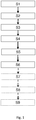
figures 1 is flowchart representing the steps of a method according to an embodiment of the invention, - o
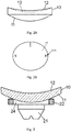
figure 2A is schematic view of an optical lens member to be manufactured according to embodiments of the invention, - o
figure 2B is a planar view of a preformed surface of a semi-finished lens member to be machined according to embodiments of the invention, - o
figure 3 is a schematic representation of a lens member and blocking device, and - o
figure 4A to 4C are schematic representation of optical lenses manufactured according to the invention. - Elements in the figures are illustrated for simplicity and clarity and have not necessarily been drawn to scale. For example, the dimensions of some of the elements in the figure may be exaggerated relative to other elements to help improve the understanding of the embodiments of the present invention.
- In the sense of the invention, a "Design" is a widely used wording known from the man skilled in the art to designate the set of parameters allowing defining an optical function of a generic optical system; each ophthalmic lens manufacturer has its own designs, particularly for aspherical lens and for progressive lens. As for an example, a progressive lens "design" results of an optimization of the progressive surface so as to restore a presbyope's ability to see clearly at all distances but also to optimally respect all physiological visual functions such as foveal vision, extra-foveal vision, binocular vision and to minimize unwanted astigmatisms.
- In the sense of the invention "manufacturing parameters" are the setting parameters of the different manufacturing devices involved in the manufacturing method. In the sense of the invention "method parameter" includes any measurable parameters on the manufacturing devices used for the manufacturing of the lens.
- According to an embodiment of the invention illustrated on
figure 1 , the method of manufacturing an optical lens according to the invention comprises at least: - a lens member providing step S1,
- a surface data providing step S2,
- a lens member blocking step S3,
- a machining step S4,
- a second markings determining step S5, and
- a second markings providing step S6.
- During the lens member providing step S1, a lens member as represented on
figure 2A is provided. - As represented on
figure 2A thelens member 10 has a first surface with a first design, for example a preformedfront surface 11. In use of the resulting finished optical lens, the preformedfront surface 11 is disposed nearest the object being viewed and asecond surface 12 to be modified by the manufacturing process to provide for example theback surface 13 of the finished optical lens, represented by the dotted line.Second surface 12 is machined by a machining tool so that theback surface 13 is orientated with respect to and distanced from thefront surface 11, according to the required optical prescription. - While in this embodiment of the invention, the first surface is the front surface of the lens member and the second surface is the back surface, it will be understood, that in alternative embodiments of the invention the first surface may be the back surface of the semi-finished lens member and the second surface may be the front surface.
- Furthermore, while in this embodiment of the invention, the back surface of the optical lens is formed by the machining process, it will be understood, that in alternative embodiments of the invention both or either surfaces of the lens may be formed by the machining process.
- Moreover, although the
surface 13 to be manufactured is represented inFigure 2A as concave, it will be appreciated that thissurface 13 could equally well be convex or any other curved surface. - With reference to
Figure 2B ,first markings 111 are provided on thefirst surface 11 oflens member 10 as reference features for defining a first reference system for positioning of the first design of thefirst surface 11. - According to an embodiment of the invention, the
markings 111 may be engraved marking have a depth of a few micrometers so as to limit the risk of disturbing the wearer of the resulting finished optical lens. - According to an alternative embodiment of the invention, the
markings 111 may be temporary markings that may be removed before providing the manufactured optical lens to the wearer. - During the surface data providing step S2, surface data corresponding to a second surface of the optical lens to be manufactured are provided. The surface data correspond to the surface to be manufactured on the
second surface 12 and the position of the second surface relative to the first surface so that the optical lens combining the manufactured backsurface 13 and the front surface provides the required optical function. The surface data can be determined according to the front preformed surface and the wearer's prescription. - During the lens member blocking step S3, the
lens member 10 is blocked in a machining position. During the machining step S4 the second surface of the optical lens is machined according to the surface data such that the desired optical properties of the optical lens are respected. - According to an embodiment of the invention, the method may comprise prior to the lens member blocking step S3 a lens blocker providing step.
- Referring now to
Figure 3 , a lens blocking device for blockinglens member 10 in the correct position for manufacturing processes comprises aninsert 21 and a blockingring 22. Blockingcast material 24 is poured into the cavity defined by the lower surface of thelens member 10, theinsert 21 and the blockingring 22. The blockingcast material 24 cools to solidify in order to provide a blocker for thelens member 10 at the desired positioning for machining. The blocker comprises the machining reference frame in which the machining data are expressed. - During the second markings determining step S5 second markings identifying a second reference system of the second surface are determined. The second markings are provided on the second surface of the optical lens during the second markings providing step S6.
- The second markings are determined at least according to optical data and observation data.
- The optical data represent the refractive properties of the optical lens. According to an embodiment of the invention, the optical data represent the prescription of the wearer. The optical data may represent the design of the first and second surfaces, the position of the second relative to the first surface, for example, the thickness and prism of the optical lens and the optical index.
- The observation data represent observation conditions in which the first and second markings are to be observed. The observation conditions may be defined by considering the observation device and the position of the manufactured lens in the observation device. The position of the manufactured optical lens in the observation device may be defined as the position of an optical lens reference frame and an observation device reference frame. The optical lens reference frame can be defined using the blocker if the lens has been maintained on the blocker, or by the normal to one of the surfaces of the optical lens passing through the prism reference point as defined by a harmonized standard ISO 8980.
- Advantageously, determining the relative positions of the two surfaces is rendered much easier, in particular when the observation of the first and second markings is realized in the observation conditions.
- According to an embodiment of the invention, the second markings are determined so as to appear at the same position as the first markings in the observation conditions when the second surface is correctly positioned relatively to the first surface. Therefore, in the observation condition the second and first markings appear superimposed when the second surface is correctly positioned relatively to the first surface.
- Therefore, a sorting of the manufactured optical lenses can be easily implemented.
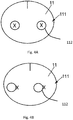
- According to an embodiment of the invention illustrated on
figure 4A and 4B , the second markings may be determined so as to take into account a positioning error tolerance. - For example as illustrated on
figure 4A , thesecond markings 112 may have circular shapes and be determined so as to appear centered over thefirst markings 111 in the observing conditions when the second surface is correctly positioned relatively to the first surface. The radius of the circular shaped second markings may be determined based on an error position tolerance. - Therefore, when the positioning error of the second and first surfaces is greater than the error position tolerance, the first markings appear outside the second markings, as illustrated on
figure 4B . - However, when the positioning error of the second and first surfaces is smaller than the error position tolerance, the first markings appear inside the second markings, as illustrated on
figure 4C . - According to an embodiment of the invention, the second markings providing step is realized with the same machining device as the machining step and the optical lens is maintained in same position. Advantageously, having the optical lens maintained in the same position during the machining and second markings providing steps guaranties that no positioning error is introduced between the second markings and the second surface.
- As illustrated on
figure 1 , according to an embodiment of the invention, the method may further comprise after the second marking providing step: - a reference system determining step S7, and
- a comparison step S8.
- Advantageously, these additional steps allow determining the relative position of the first and second surface of the machined optical lens.
- During the reference system determining step S7, the positions of the first and second markings are determined in the observation conditions corresponding to the observation data. The first and second reference systems can be determined based on the positions of the first and second markings.
- The positioning error between the first and second surfaces is determined by comparing the positions of the first and second reference systems during the comparison step S8.
- According to an embodiment of the invention, the positions of the first and second reference systems are compared in a common reference system, for example in the manufactured optical lens reference frame. As indicated previously, the optical lens reference frame can be defined using the blocker if the lens has been maintained on the blocker, or by the normal to one of the surfaces of the optical lens passing between the reference-markings that have been made mandatory by a harmonized standard ISO 8980.
- According to an embodiment of the invention, the relative position between the first and second markings is determined in the observation condition by an operator. For example, the observation condition may consist in placing the optical lens at a predetermined distance of a light source and of the operator's eye. During the second markings determining step, the second markings may be determined so as to appear to the operator superimposed with the first marking when the second surface is correctly positioned relative to the first surface or as illustrated on
figure 4a to 4C with an error tolerance. - Advantageously, the operator may very easily check the relative position of the first and second surfaces.
- The observation condition could also be having an image of a light source be projected on to a screen through the machined optical lens. The operator could then observe the markings on the projection screen.
- As illustrated on
figure 1 , the method according to the invention may also comprise a sorting step S9, during which the manufactured optical lens is accepted if the positioning error between the first and second surfaces is smaller than or equal to a threshold value and is set aside if the positioning error between the first and second surfaces is greater than said threshold value. - According to different embodiments of the invention, the threshold value may depend on the prescription of the wearer and/or the design of one or both surfaces and/or the curvature variations of one or both of the surfaces.
- The invention also relates to a method for controlling a lens manufacturing process. The method for controlling a lens manufacturing process comprises the steps of:
- a) manufacturing an optical lens according to a manufacturing method of the invention using a manufacturing device,
- b) determining the positioning error of the first and second surfaces of the optical lens,
- c) recording the determined positioning error,
- d) repeating regularly step a) to c) and checking over time the evolution of the positioning error.
- The evolution of at least one parameter of the manufacturing device used during the lens manufacturing process is checked over time and the evolution over time of the positioning error of the first and second surfaces of the optical lens is related with the evolution over time of the at least one parameter of the manufacturing device.
- Advantageously, the method according to the invention allows controlling certain method or device parameters of the machining process. Indeed, the position error can be correlated to some of the machining device parameters, thus controlling the evolution over time of the positioning error can help identify a drift or shift of a machining device parameter.
- According to an embodiment of the invention, the optical lenses manufactured when repeating step a) may be different optical lenses from one repetition to the other.
- According to an embodiment of the invention the optical lens manufactured during step a) may be a master lens.
- The master lens has a different geometrical and/or optical parameter and/or is made of a different material than the lenses to be manufactured during the manufacturing process.
- The choice of the master lens can be done so as to simplify the observation conditions, for example the master lens may comprise two plane and parallel surfaces.
- The choice of the master lens can be done so as to amplify the sensibility of certain parameter to the process parameters. For example, the master lens is made of a material and has a design such as its optical parameters are more sensible to a modification of the process parameter that the usual manufactured lenses.
- Advantageously, the use of a master lens makes the correlation between a shift in the positioning error and a parameter of the manufacturing device used during the lens manufacturing process easier and more reliable.
- For example, the master lens may be manufactured daily or several times per day or a regular basis not every day so as to check the parameters of the manufacturing device.
- The invention has been described above with the aid of embodiments without limitation of the general inventive concept.
the evolution of at least one parameter of the manufacturing device used during the lens manufacturing process is checked over time and the evolution over time of the positioning error of the first and second surfaces of the optical lens is related with the evolution over time of the at least one parameter of the manufacturing device.
the evolution of at least one parameter of the manufacturing device used during the lens manufacturing process is checked over time and the evolution over time of the positioning error of the first and second surfaces of the master lens is related with the evolution over time of the at least one parameter of the manufacturing device.
Claims (15)
- Method of manufacturing an optical lens, the method comprising:• a lens member (10) providing step (S1) during which a lens member (10) comprising a first surface (11) and a first reference system of the first surface (11) is provided, the first reference system being identified by first markings (111) on the first surface (11),• a surface data providing step (S2) during which surface data corresponding to a second surface (12) and the position of the second surface (12) relative to the first surface (11) of the optical lens to be manufactured are provided,• a lens member blocking step (S3) during which the lens member (10) is blocked in a machining position,• a machining step (S4) during which the second surface (12) of the optical lens is machined according to the surface data, characterised in that the method further comprises:• a second markings (112) determining step (S5) during which second markings (112) identifying a second reference system of the second surface (12) are determined according at least to optical data representing the refractive properties of the optical lens and to observation data representing observation conditions in which the first (111) and second markings (112) are to be observed, and• a second markings (112) providing step (S6) during which the second markings (112) are provided on the second surface (12) of the optical lens.
- The method according to claim 1, wherein the method further comprises:• an reference system determining step (S7) during which the first and second reference systems are determined by determining the positions of the first (111) and second markings (112) in the observation conditions corresponding to the observation data, and• a comparison step (S8) during which the positions of the first and second reference systems are compared so as to determine the positioning error between the first (11) and second surfaces (12).
- The method according to claim 2, wherein the method further comprises a sorting step (S9) during which the manufactured optical lens is accepted if the positioning error between the first (11) and second surfaces (12) is smaller than or equal to a threshold value and is set aside if the positioning error between the first (11) and second surfaces (12) is greater than said threshold value.
- The method according to claim 2 or 3, wherein during the reference system determining step the positions on the first (111) and second markings (112) are measured using a measuring optical device and the observation data represents at least the position of the optical lens relative to the measuring optical device.
- The method according to claim 2 or 3, wherein during the reference system determining step, the relative position between the first (111) and second markings (112) is determined in the observation conditions by an operator.
- The method according to any of the preceding claims, wherein during the second marking (112) determining step the second markings (112) are determined so as to appear at the same position as the first markings (111) in the observation conditions when the second surface (12) is correctly positioned relatively to the first surface (11).
- The method according to any of the preceding claims, wherein during the second marking (112) determining step the second markings (112) are determined so as to take into account a positioning error tolerance.
- The method according to any of the preceding claims, wherein the optical data represent at least the design of the first (11) and second surfaces (12) and the relative position of the second surface (12) relative to the first surface (11).
- The method according to any of the preceding claims, wherein during the second markings (112) providing step the optical lens is blocked in the same position as during the machining step.
- The method according to any of the preceding claims, wherein the first (111) and/or second markings (112) are temporary markings.
- The method according to any of the preceding claims, wherein the optical data represent at least the prescription of the wearer for which the optical lens is manufactured.
- A method for controlling a lens manufacturing process comprising:• an optical lens manufacturing step during which an optical lens is manufactured according to a manufacturing method as claimed in any of the preceding claims using a manufacturing device,• a positioning error determining step during which the positioning error of the first (11) and second surfaces (12) of the optical lens is determined,• a recording step during which the positioning error is recorded,wherein, the method further comprises repeating regularly optical lens manufacturing, positioning error determining and recording steps and checking the evolution of the positioning error over time, and the evolution of at least one parameter of the manufacturing device used during the lens manufacturing process is checked over time and the evolution over time of the positioning error of the first (11) and second surfaces (12) of the optical lens is related with the evolution over time of the at least one parameter of the manufacturing device.
- A method for controlling a lens manufacturing process comprising:• a master lens manufacturing step during which a master lens is manufactured according to a manufacturing method as claimed in any of claims 1 to 10 using a manufacturing device,• a positioning error determining step during which the positioning error of the first (11) and second surfaces (12) of the master lens is determined,• a recording step during which the positioning error is recording,wherein, the method further comprises repeating regularly master lens manufacturing, positioning error determining and recording steps and checking the evolution of the positioning error over time, and the evolution of at least one parameter of the manufacturing device used during the lens manufacturing process is checked over time and the evolution over time of the positioning error of the first (11) and second surfaces (12) of the master lens is related with the evolution over time of the at least one parameter of the manufacturing device.
- A computer program product comprising one or more stored sequences of instructions that are accessible to a processor and which, when executed by the processor, causes the processor to carry out the steps of any of claims 1 to 13.
- A computer readable medium carrying one or more sequences of instructions of the computer program product of claim 14.
Priority Applications (1)
| Application Number | Priority Date | Filing Date | Title |
|---|---|---|---|
| EP13795699.1A EP2919973B1 (en) | 2012-11-19 | 2013-10-30 | Method of manufacturing an optical lens |
Applications Claiming Priority (3)
| Application Number | Priority Date | Filing Date | Title |
|---|---|---|---|
| EP12306433 | 2012-11-19 | ||
| EP13795699.1A EP2919973B1 (en) | 2012-11-19 | 2013-10-30 | Method of manufacturing an optical lens |
| PCT/EP2013/072732 WO2014075925A1 (en) | 2012-11-19 | 2013-10-30 | Method of manufacturing an optical lens |
Publications (2)
| Publication Number | Publication Date |
|---|---|
| EP2919973A1 EP2919973A1 (en) | 2015-09-23 |
| EP2919973B1 true EP2919973B1 (en) | 2018-12-19 |
Family
ID=47603156
Family Applications (1)
| Application Number | Title | Priority Date | Filing Date |
|---|---|---|---|
| EP13795699.1A Active EP2919973B1 (en) | 2012-11-19 | 2013-10-30 | Method of manufacturing an optical lens |
Country Status (9)
| Country | Link |
|---|---|
| US (1) | US20150293380A1 (en) |
| EP (1) | EP2919973B1 (en) |
| JP (1) | JP6590698B2 (en) |
| KR (1) | KR20150086475A (en) |
| CN (1) | CN104797408B (en) |
| BR (1) | BR112015011532A8 (en) |
| CO (1) | CO7350645A2 (en) |
| MX (1) | MX352268B (en) |
| WO (1) | WO2014075925A1 (en) |
Families Citing this family (3)
| Publication number | Priority date | Publication date | Assignee | Title |
|---|---|---|---|---|
| CN105607210A (en) * | 2015-12-29 | 2016-05-25 | 捷西迪(广州)光学科技有限公司 | Optical barrel processing system and processing method thereof |
| EP3467465B1 (en) * | 2017-10-04 | 2021-03-03 | Essilor International | A system and a method for monitoring the position of a blocking device, and a method of edging an ophthalmic lens |
| CN117124483B (en) * | 2023-07-13 | 2024-03-08 | 同济大学 | Free-form surface prism high-precision compensation processing method based on online and offline detection |
Family Cites Families (11)
| Publication number | Priority date | Publication date | Assignee | Title |
|---|---|---|---|---|
| US5343657A (en) * | 1992-09-18 | 1994-09-06 | Venture Tape Corporation | Method and apparatus for masking removable optical lens markings during lens grinding |
| ID20540A (en) * | 1997-04-07 | 1999-01-07 | Bausch & Lomb | METHOD FOR UNTUYK IDENTIFY THE CHARACTERISTICS OF THE CONTACT LENS |
| CN100458496C (en) * | 2003-06-27 | 2009-02-04 | 精工爱普生株式会社 | Production method for glasses lens, marking device, marking system, glasses lens |
| US6951392B2 (en) * | 2003-07-09 | 2005-10-04 | 3M Innovative Properties Company | Lens having at least one lens centration mark and methods of making and using same |
| US7980920B2 (en) * | 2004-06-30 | 2011-07-19 | Hoya Corporation | Spectacle lens manufacturing method |
| US20060145372A1 (en) * | 2004-12-30 | 2006-07-06 | Jones Thomas G | Optical tool assembly for improved RCW and lens edge formation |
| JP4863112B2 (en) * | 2006-09-15 | 2012-01-25 | Nltテクノロジー株式会社 | Optical element array, display device, and manufacturing method of display device |
| FR2915289B1 (en) * | 2007-04-18 | 2009-07-03 | Essilor Int | DEVICE AND METHOD FOR PREPARING AN OPHTHALMIC LENS FOR MACHINING |
| DE602008004302D1 (en) * | 2008-02-25 | 2011-02-17 | Satisloh Ag | Block piece for holding an optical workpiece, in particular a spectacle lens, for its processing and method for producing spectacle lenses according to a recipe |
| EP2199021A1 (en) * | 2008-12-22 | 2010-06-23 | Essilor International (Compagnie Générale D'Optique) | A method of and an apparatus for manufacturing an optical lens |
| JP5650474B2 (en) * | 2010-09-13 | 2015-01-07 | 株式会社クラレ | Manufacturing method of Fresnel lens sheet |
-
2013
- 2013-10-30 CN CN201380060224.5A patent/CN104797408B/en not_active Expired - Fee Related
- 2013-10-30 US US14/443,320 patent/US20150293380A1/en not_active Abandoned
- 2013-10-30 WO PCT/EP2013/072732 patent/WO2014075925A1/en active Application Filing
- 2013-10-30 EP EP13795699.1A patent/EP2919973B1/en active Active
- 2013-10-30 KR KR1020157012996A patent/KR20150086475A/en not_active Application Discontinuation
- 2013-10-30 BR BR112015011532A patent/BR112015011532A8/en not_active Application Discontinuation
- 2013-10-30 MX MX2015006244A patent/MX352268B/en active IP Right Grant
- 2013-10-30 JP JP2015542207A patent/JP6590698B2/en not_active Expired - Fee Related
-
2015
- 2015-05-19 CO CO15112830A patent/CO7350645A2/en unknown
Non-Patent Citations (1)
| Title |
|---|
| None * |
Also Published As
| Publication number | Publication date |
|---|---|
| WO2014075925A1 (en) | 2014-05-22 |
| JP6590698B2 (en) | 2019-10-16 |
| CN104797408A (en) | 2015-07-22 |
| BR112015011532A2 (en) | 2017-07-11 |
| KR20150086475A (en) | 2015-07-28 |
| US20150293380A1 (en) | 2015-10-15 |
| BR112015011532A8 (en) | 2018-08-14 |
| JP2016503517A (en) | 2016-02-04 |
| MX2015006244A (en) | 2015-12-09 |
| EP2919973A1 (en) | 2015-09-23 |
| CN104797408B (en) | 2017-01-18 |
| MX352268B (en) | 2017-11-16 |
| CO7350645A2 (en) | 2015-08-10 |
Similar Documents
| Publication | Publication Date | Title |
|---|---|---|
| EP2919974B1 (en) | Method of manufacturing an optical lens | |
| US20160011434A1 (en) | Optical Lens Member Comprising A Sub-Surface Referencing Element | |
| EP2961592B1 (en) | Method for providing a referencing element to an optical lens member | |
| JP5766952B2 (en) | Determination method of bevel shape of ophthalmic lens | |
| CN101960360A (en) | Method according to given spectacle frame calculating optical system | |
| US9104045B2 (en) | Method of determining parameters for fitting an ophthalmic lens to a frame | |
| AU2012350860B2 (en) | A method of manufacturing an optical lens | |
| EP2919973B1 (en) | Method of manufacturing an optical lens | |
| CN103998215A (en) | A method of processing an order request for an ophthalmic lens | |
| KR102210773B1 (en) | Method of taping an optical lens member | |
| JP2016503517A5 (en) | ||
| CN103998181B (en) | A method of blocking an optical lens | |
| US20160139428A1 (en) | Method For Optimizing A Measured Contour Of A Spectacle Frame | |
| EP3628441A1 (en) | Semi-finished lens, method and device for manufacturing an optical lens | |
| KR20180011372A (en) | A method of manufacturing an optical lens | |
| EP3187918A1 (en) | Marking method for marking an optical article destined to a wearer |
Legal Events
| Date | Code | Title | Description |
|---|---|---|---|
| PUAI | Public reference made under article 153(3) epc to a published international application that has entered the european phase |
Free format text: ORIGINAL CODE: 0009012 |
|
| 17P | Request for examination filed |
Effective date: 20150611 |
|
| AK | Designated contracting states |
Kind code of ref document: A1 Designated state(s): AL AT BE BG CH CY CZ DE DK EE ES FI FR GB GR HR HU IE IS IT LI LT LU LV MC MK MT NL NO PL PT RO RS SE SI SK SM TR |
|
| AX | Request for extension of the european patent |
Extension state: BA ME |
|
| DAX | Request for extension of the european patent (deleted) | ||
| RAP1 | Party data changed (applicant data changed or rights of an application transferred) |
Owner name: ESSILOR INTERNATIONAL |
|
| GRAP | Despatch of communication of intention to grant a patent |
Free format text: ORIGINAL CODE: EPIDOSNIGR1 |
|
| STAA | Information on the status of an ep patent application or granted ep patent |
Free format text: STATUS: GRANT OF PATENT IS INTENDED |
|
| INTG | Intention to grant announced |
Effective date: 20180906 |
|
| GRAS | Grant fee paid |
Free format text: ORIGINAL CODE: EPIDOSNIGR3 |
|
| GRAA | (expected) grant |
Free format text: ORIGINAL CODE: 0009210 |
|
| STAA | Information on the status of an ep patent application or granted ep patent |
Free format text: STATUS: THE PATENT HAS BEEN GRANTED |
|
| AK | Designated contracting states |
Kind code of ref document: B1 Designated state(s): AL AT BE BG CH CY CZ DE DK EE ES FI FR GB GR HR HU IE IS IT LI LT LU LV MC MK MT NL NO PL PT RO RS SE SI SK SM TR |
|
| REG | Reference to a national code |
Ref country code: GB Ref legal event code: FG4D |
|
| REG | Reference to a national code |
Ref country code: CH Ref legal event code: EP |
|
| REG | Reference to a national code |
Ref country code: DE Ref legal event code: R096 Ref document number: 602013048505 Country of ref document: DE |
|
| REG | Reference to a national code |
Ref country code: IE Ref legal event code: FG4D |
|
| REG | Reference to a national code |
Ref country code: AT Ref legal event code: REF Ref document number: 1078230 Country of ref document: AT Kind code of ref document: T Effective date: 20190115 |
|
| REG | Reference to a national code |
Ref country code: NL Ref legal event code: MP Effective date: 20181219 |
|
| PG25 | Lapsed in a contracting state [announced via postgrant information from national office to epo] |
Ref country code: BG Free format text: LAPSE BECAUSE OF FAILURE TO SUBMIT A TRANSLATION OF THE DESCRIPTION OR TO PAY THE FEE WITHIN THE PRESCRIBED TIME-LIMIT Effective date: 20190319 Ref country code: HR Free format text: LAPSE BECAUSE OF FAILURE TO SUBMIT A TRANSLATION OF THE DESCRIPTION OR TO PAY THE FEE WITHIN THE PRESCRIBED TIME-LIMIT Effective date: 20181219 Ref country code: NO Free format text: LAPSE BECAUSE OF FAILURE TO SUBMIT A TRANSLATION OF THE DESCRIPTION OR TO PAY THE FEE WITHIN THE PRESCRIBED TIME-LIMIT Effective date: 20190319 Ref country code: LT Free format text: LAPSE BECAUSE OF FAILURE TO SUBMIT A TRANSLATION OF THE DESCRIPTION OR TO PAY THE FEE WITHIN THE PRESCRIBED TIME-LIMIT Effective date: 20181219 Ref country code: LV Free format text: LAPSE BECAUSE OF FAILURE TO SUBMIT A TRANSLATION OF THE DESCRIPTION OR TO PAY THE FEE WITHIN THE PRESCRIBED TIME-LIMIT Effective date: 20181219 Ref country code: FI Free format text: LAPSE BECAUSE OF FAILURE TO SUBMIT A TRANSLATION OF THE DESCRIPTION OR TO PAY THE FEE WITHIN THE PRESCRIBED TIME-LIMIT Effective date: 20181219 |
|
| REG | Reference to a national code |
Ref country code: LT Ref legal event code: MG4D |
|
| REG | Reference to a national code |
Ref country code: AT Ref legal event code: MK05 Ref document number: 1078230 Country of ref document: AT Kind code of ref document: T Effective date: 20181219 |
|
| PG25 | Lapsed in a contracting state [announced via postgrant information from national office to epo] |
Ref country code: GR Free format text: LAPSE BECAUSE OF FAILURE TO SUBMIT A TRANSLATION OF THE DESCRIPTION OR TO PAY THE FEE WITHIN THE PRESCRIBED TIME-LIMIT Effective date: 20190320 Ref country code: AL Free format text: LAPSE BECAUSE OF FAILURE TO SUBMIT A TRANSLATION OF THE DESCRIPTION OR TO PAY THE FEE WITHIN THE PRESCRIBED TIME-LIMIT Effective date: 20181219 Ref country code: SE Free format text: LAPSE BECAUSE OF FAILURE TO SUBMIT A TRANSLATION OF THE DESCRIPTION OR TO PAY THE FEE WITHIN THE PRESCRIBED TIME-LIMIT Effective date: 20181219 Ref country code: RS Free format text: LAPSE BECAUSE OF FAILURE TO SUBMIT A TRANSLATION OF THE DESCRIPTION OR TO PAY THE FEE WITHIN THE PRESCRIBED TIME-LIMIT Effective date: 20181219 |
|
| PG25 | Lapsed in a contracting state [announced via postgrant information from national office to epo] |
Ref country code: NL Free format text: LAPSE BECAUSE OF FAILURE TO SUBMIT A TRANSLATION OF THE DESCRIPTION OR TO PAY THE FEE WITHIN THE PRESCRIBED TIME-LIMIT Effective date: 20181219 |
|
| PG25 | Lapsed in a contracting state [announced via postgrant information from national office to epo] |
Ref country code: IT Free format text: LAPSE BECAUSE OF FAILURE TO SUBMIT A TRANSLATION OF THE DESCRIPTION OR TO PAY THE FEE WITHIN THE PRESCRIBED TIME-LIMIT Effective date: 20181219 Ref country code: PL Free format text: LAPSE BECAUSE OF FAILURE TO SUBMIT A TRANSLATION OF THE DESCRIPTION OR TO PAY THE FEE WITHIN THE PRESCRIBED TIME-LIMIT Effective date: 20181219 Ref country code: ES Free format text: LAPSE BECAUSE OF FAILURE TO SUBMIT A TRANSLATION OF THE DESCRIPTION OR TO PAY THE FEE WITHIN THE PRESCRIBED TIME-LIMIT Effective date: 20181219 Ref country code: PT Free format text: LAPSE BECAUSE OF FAILURE TO SUBMIT A TRANSLATION OF THE DESCRIPTION OR TO PAY THE FEE WITHIN THE PRESCRIBED TIME-LIMIT Effective date: 20190419 Ref country code: CZ Free format text: LAPSE BECAUSE OF FAILURE TO SUBMIT A TRANSLATION OF THE DESCRIPTION OR TO PAY THE FEE WITHIN THE PRESCRIBED TIME-LIMIT Effective date: 20181219 |
|
| PG25 | Lapsed in a contracting state [announced via postgrant information from national office to epo] |
Ref country code: SK Free format text: LAPSE BECAUSE OF FAILURE TO SUBMIT A TRANSLATION OF THE DESCRIPTION OR TO PAY THE FEE WITHIN THE PRESCRIBED TIME-LIMIT Effective date: 20181219 Ref country code: IS Free format text: LAPSE BECAUSE OF FAILURE TO SUBMIT A TRANSLATION OF THE DESCRIPTION OR TO PAY THE FEE WITHIN THE PRESCRIBED TIME-LIMIT Effective date: 20190419 Ref country code: RO Free format text: LAPSE BECAUSE OF FAILURE TO SUBMIT A TRANSLATION OF THE DESCRIPTION OR TO PAY THE FEE WITHIN THE PRESCRIBED TIME-LIMIT Effective date: 20181219 Ref country code: EE Free format text: LAPSE BECAUSE OF FAILURE TO SUBMIT A TRANSLATION OF THE DESCRIPTION OR TO PAY THE FEE WITHIN THE PRESCRIBED TIME-LIMIT Effective date: 20181219 Ref country code: SM Free format text: LAPSE BECAUSE OF FAILURE TO SUBMIT A TRANSLATION OF THE DESCRIPTION OR TO PAY THE FEE WITHIN THE PRESCRIBED TIME-LIMIT Effective date: 20181219 |
|
| REG | Reference to a national code |
Ref country code: DE Ref legal event code: R097 Ref document number: 602013048505 Country of ref document: DE |
|
| PLBE | No opposition filed within time limit |
Free format text: ORIGINAL CODE: 0009261 |
|
| STAA | Information on the status of an ep patent application or granted ep patent |
Free format text: STATUS: NO OPPOSITION FILED WITHIN TIME LIMIT |
|
| PG25 | Lapsed in a contracting state [announced via postgrant information from national office to epo] |
Ref country code: DK Free format text: LAPSE BECAUSE OF FAILURE TO SUBMIT A TRANSLATION OF THE DESCRIPTION OR TO PAY THE FEE WITHIN THE PRESCRIBED TIME-LIMIT Effective date: 20181219 Ref country code: AT Free format text: LAPSE BECAUSE OF FAILURE TO SUBMIT A TRANSLATION OF THE DESCRIPTION OR TO PAY THE FEE WITHIN THE PRESCRIBED TIME-LIMIT Effective date: 20181219 |
|
| 26N | No opposition filed |
Effective date: 20190920 |
|
| PG25 | Lapsed in a contracting state [announced via postgrant information from national office to epo] |
Ref country code: SI Free format text: LAPSE BECAUSE OF FAILURE TO SUBMIT A TRANSLATION OF THE DESCRIPTION OR TO PAY THE FEE WITHIN THE PRESCRIBED TIME-LIMIT Effective date: 20181219 |
|
| PG25 | Lapsed in a contracting state [announced via postgrant information from national office to epo] |
Ref country code: TR Free format text: LAPSE BECAUSE OF FAILURE TO SUBMIT A TRANSLATION OF THE DESCRIPTION OR TO PAY THE FEE WITHIN THE PRESCRIBED TIME-LIMIT Effective date: 20181219 |
|
| PG25 | Lapsed in a contracting state [announced via postgrant information from national office to epo] |
Ref country code: MC Free format text: LAPSE BECAUSE OF FAILURE TO SUBMIT A TRANSLATION OF THE DESCRIPTION OR TO PAY THE FEE WITHIN THE PRESCRIBED TIME-LIMIT Effective date: 20181219 |
|
| REG | Reference to a national code |
Ref country code: CH Ref legal event code: PL |
|
| PG25 | Lapsed in a contracting state [announced via postgrant information from national office to epo] |
Ref country code: LI Free format text: LAPSE BECAUSE OF NON-PAYMENT OF DUE FEES Effective date: 20191031 Ref country code: LU Free format text: LAPSE BECAUSE OF NON-PAYMENT OF DUE FEES Effective date: 20191030 Ref country code: CH Free format text: LAPSE BECAUSE OF NON-PAYMENT OF DUE FEES Effective date: 20191031 |
|
| REG | Reference to a national code |
Ref country code: BE Ref legal event code: MM Effective date: 20191031 |
|
| PG25 | Lapsed in a contracting state [announced via postgrant information from national office to epo] |
Ref country code: BE Free format text: LAPSE BECAUSE OF NON-PAYMENT OF DUE FEES Effective date: 20191031 |
|
| PG25 | Lapsed in a contracting state [announced via postgrant information from national office to epo] |
Ref country code: IE Free format text: LAPSE BECAUSE OF NON-PAYMENT OF DUE FEES Effective date: 20191030 |
|
| PG25 | Lapsed in a contracting state [announced via postgrant information from national office to epo] |
Ref country code: CY Free format text: LAPSE BECAUSE OF FAILURE TO SUBMIT A TRANSLATION OF THE DESCRIPTION OR TO PAY THE FEE WITHIN THE PRESCRIBED TIME-LIMIT Effective date: 20181219 |
|
| PG25 | Lapsed in a contracting state [announced via postgrant information from national office to epo] |
Ref country code: MT Free format text: LAPSE BECAUSE OF FAILURE TO SUBMIT A TRANSLATION OF THE DESCRIPTION OR TO PAY THE FEE WITHIN THE PRESCRIBED TIME-LIMIT Effective date: 20181219 Ref country code: HU Free format text: LAPSE BECAUSE OF FAILURE TO SUBMIT A TRANSLATION OF THE DESCRIPTION OR TO PAY THE FEE WITHIN THE PRESCRIBED TIME-LIMIT; INVALID AB INITIO Effective date: 20131030 |
|
| PG25 | Lapsed in a contracting state [announced via postgrant information from national office to epo] |
Ref country code: MK Free format text: LAPSE BECAUSE OF FAILURE TO SUBMIT A TRANSLATION OF THE DESCRIPTION OR TO PAY THE FEE WITHIN THE PRESCRIBED TIME-LIMIT Effective date: 20181219 |
|
| P01 | Opt-out of the competence of the unified patent court (upc) registered |
Effective date: 20230525 |
|
| PGFP | Annual fee paid to national office [announced via postgrant information from national office to epo] |
Ref country code: GB Payment date: 20231027 Year of fee payment: 11 |
|
| PGFP | Annual fee paid to national office [announced via postgrant information from national office to epo] |
Ref country code: FR Payment date: 20231025 Year of fee payment: 11 Ref country code: DE Payment date: 20231027 Year of fee payment: 11 |