EP2919729B1 - Tympanostomy tube and insertion device - Google Patents
Tympanostomy tube and insertion device Download PDFInfo
- Publication number
- EP2919729B1 EP2919729B1 EP13786476.5A EP13786476A EP2919729B1 EP 2919729 B1 EP2919729 B1 EP 2919729B1 EP 13786476 A EP13786476 A EP 13786476A EP 2919729 B1 EP2919729 B1 EP 2919729B1
- Authority
- EP
- European Patent Office
- Prior art keywords
- tube
- cartridge
- tympanostomy tube
- applicator
- inserter
- Prior art date
- Legal status (The legal status is an assumption and is not a legal conclusion. Google has not performed a legal analysis and makes no representation as to the accuracy of the status listed.)
- Active
Links
- 0 C1C2=CC1**2 Chemical compound C1C2=CC1**2 0.000 description 1
Images






Classifications
-
- A—HUMAN NECESSITIES
- A61—MEDICAL OR VETERINARY SCIENCE; HYGIENE
- A61F—FILTERS IMPLANTABLE INTO BLOOD VESSELS; PROSTHESES; DEVICES PROVIDING PATENCY TO, OR PREVENTING COLLAPSING OF, TUBULAR STRUCTURES OF THE BODY, e.g. STENTS; ORTHOPAEDIC, NURSING OR CONTRACEPTIVE DEVICES; FOMENTATION; TREATMENT OR PROTECTION OF EYES OR EARS; BANDAGES, DRESSINGS OR ABSORBENT PADS; FIRST-AID KITS
- A61F11/00—Methods or devices for treatment of the ears or hearing sense; Non-electric hearing aids; Methods or devices for enabling ear patients to achieve auditory perception through physiological senses other than hearing sense; Protective devices for the ears, carried on the body or in the hand
- A61F11/20—Ear surgery
- A61F11/202—Surgical middle-ear ventilation or drainage, e.g. permanent; Implants therefor
-
- A—HUMAN NECESSITIES
- A61—MEDICAL OR VETERINARY SCIENCE; HYGIENE
- A61B—DIAGNOSIS; SURGERY; IDENTIFICATION
- A61B17/00—Surgical instruments, devices or methods
- A61B2017/0042—Surgical instruments, devices or methods with special provisions for gripping
- A61B2017/00424—Surgical instruments, devices or methods with special provisions for gripping ergonomic, e.g. fitting in fist
-
- A—HUMAN NECESSITIES
- A61—MEDICAL OR VETERINARY SCIENCE; HYGIENE
- A61F—FILTERS IMPLANTABLE INTO BLOOD VESSELS; PROSTHESES; DEVICES PROVIDING PATENCY TO, OR PREVENTING COLLAPSING OF, TUBULAR STRUCTURES OF THE BODY, e.g. STENTS; ORTHOPAEDIC, NURSING OR CONTRACEPTIVE DEVICES; FOMENTATION; TREATMENT OR PROTECTION OF EYES OR EARS; BANDAGES, DRESSINGS OR ABSORBENT PADS; FIRST-AID KITS
- A61F2250/00—Special features of prostheses classified in groups A61F2/00 - A61F2/26 or A61F2/82 or A61F9/00 or A61F11/00 or subgroups thereof
- A61F2250/0001—Means for transferring electromagnetic energy to implants
-
- A—HUMAN NECESSITIES
- A61—MEDICAL OR VETERINARY SCIENCE; HYGIENE
- A61F—FILTERS IMPLANTABLE INTO BLOOD VESSELS; PROSTHESES; DEVICES PROVIDING PATENCY TO, OR PREVENTING COLLAPSING OF, TUBULAR STRUCTURES OF THE BODY, e.g. STENTS; ORTHOPAEDIC, NURSING OR CONTRACEPTIVE DEVICES; FOMENTATION; TREATMENT OR PROTECTION OF EYES OR EARS; BANDAGES, DRESSINGS OR ABSORBENT PADS; FIRST-AID KITS
- A61F2250/00—Special features of prostheses classified in groups A61F2/00 - A61F2/26 or A61F2/82 or A61F9/00 or A61F11/00 or subgroups thereof
- A61F2250/0004—Special features of prostheses classified in groups A61F2/00 - A61F2/26 or A61F2/82 or A61F9/00 or A61F11/00 or subgroups thereof adjustable
- A61F2250/001—Special features of prostheses classified in groups A61F2/00 - A61F2/26 or A61F2/82 or A61F9/00 or A61F11/00 or subgroups thereof adjustable for adjusting a diameter
-
- A—HUMAN NECESSITIES
- A61—MEDICAL OR VETERINARY SCIENCE; HYGIENE
- A61F—FILTERS IMPLANTABLE INTO BLOOD VESSELS; PROSTHESES; DEVICES PROVIDING PATENCY TO, OR PREVENTING COLLAPSING OF, TUBULAR STRUCTURES OF THE BODY, e.g. STENTS; ORTHOPAEDIC, NURSING OR CONTRACEPTIVE DEVICES; FOMENTATION; TREATMENT OR PROTECTION OF EYES OR EARS; BANDAGES, DRESSINGS OR ABSORBENT PADS; FIRST-AID KITS
- A61F2250/00—Special features of prostheses classified in groups A61F2/00 - A61F2/26 or A61F2/82 or A61F9/00 or A61F11/00 or subgroups thereof
- A61F2250/0014—Special features of prostheses classified in groups A61F2/00 - A61F2/26 or A61F2/82 or A61F9/00 or A61F11/00 or subgroups thereof having different values of a given property or geometrical feature, e.g. mechanical property or material property, at different locations within the same prosthesis
- A61F2250/0039—Special features of prostheses classified in groups A61F2/00 - A61F2/26 or A61F2/82 or A61F9/00 or A61F11/00 or subgroups thereof having different values of a given property or geometrical feature, e.g. mechanical property or material property, at different locations within the same prosthesis differing in diameter
Definitions
- the handle 2 is made up of two ergonomic case moulded plastics halves 5(a) and 5(b).
- the cartridge 3 is also made from components 13(a) and 13(b) which snap fit together during assembly.
- the cartridge plug 12 has a tab 12(a) which mates with a slot 11(a) in the socket 11. Once the cartridge plug 12 is fully inserted into the handle socket 11 the cartridge 3 is rotated to lock it into place. On further rotation of the cartridge 3, the tab 12(a) locks into different mating parts of the slot 11(a), which provides the user with different variations of device setup.
- Fig. 3 shows the cartridge 3 set at 90° to the handle 2.
- Fig. 4 shows a sectioned view of the handle 2 in a resting configuration prior to connection of the cartridge 3.
- the handle button 10 has ratchets 30 and 31 which are attached to a rotating drum 32.
- a part 34 of the drum 32 houses a return spring 35 to provide upward bias to the button 10.
- the ratchets 30 and 31 mate with a slider 40 which has opposing ratchet teeth 41 and 42.
- a compression component 45 is mated coaxially to the slider 40 and both are assembled within a compression spring 46.
- a rubber ring 50 is housed within the compression component 45 to provide damping during use, and there is a complementary damper sleeve 50(a) at the opposite (right side as viewed in Fig. 4 ) end of the slider 40.
- the slider 40 is in two parts for manufacturing purposes, however, it may alternatively be moulded as an integral component..
- the rod which terminates in an inverted pyramid-shaped tip 122 and holds the balloon 204, will initially retract into the shaft 201. This will aid in ejection of the tube 203 by pushing it against the shoulder 202.Further release of the trigger 111 causes the tube inserter assembly 200 to return into the cylindrical body. The head 103 is then removed from the patient's ear canal.
- the tympanostomy tube may be of any other known overall outline shape, as set out above.
- the spring mechanism in the handle may have a spring with is extended to load it rather than being compressed.
Landscapes
- Health & Medical Sciences (AREA)
- Life Sciences & Earth Sciences (AREA)
- Heart & Thoracic Surgery (AREA)
- Vascular Medicine (AREA)
- Acoustics & Sound (AREA)
- Biophysics (AREA)
- Otolaryngology (AREA)
- Psychology (AREA)
- Engineering & Computer Science (AREA)
- Biomedical Technology (AREA)
- Surgery (AREA)
- Physics & Mathematics (AREA)
- Animal Behavior & Ethology (AREA)
- General Health & Medical Sciences (AREA)
- Public Health (AREA)
- Veterinary Medicine (AREA)
- Media Introduction/Drainage Providing Device (AREA)
- Prostheses (AREA)
- Endoscopes (AREA)
- Surgical Instruments (AREA)
Description
- The invention relates a tympanostomy tube applicator and a tympanostomy tube as defined by the claims. Insofar as the terms "invention" and/or "embodiment" are used in the following, and/or features are presented as being optional, this should be interpreted in such a way that the only protection sought is that of the invention as claimed.
- A tympanostomy tube (also known as a tube) is a small tube inserted into the tympanic membrane in order to ventilate the middle ear for a prolonged period of time, and to prevent the accumulation of fluid in the middle ear. The tube is usually inserted under general aesthetic in a surgical environment. The surgeon will use various tools to firstly clean the outer ear canal, will then use a myringotomy knife to make an incision in the tympanic membrane, and will then use a suction tip to remove fluid from the middle ear. Finally, the surgeon will use a combination of forceps and probe to insert the tympanostomy tube.
-
US2009/0209972 (Loushin) describes an insertion device which deforms the ends of a ventilation device to a flange-like structure. It does so by use of a bumper or stop on a cutting member. The bumper or stop may be inflatable. -
US2009/0099573 (Gonzales) describes a device for inserting a tympanostomy tube. - The invention is directed towards achieving a simpler procedure.
- According to the invention, there is provided a tympanostomy tube applicator as set out in
claim 1. - By pressing the tube from within at the distal end at least, the applicator can reliably re-configure the tube in situ so that the desired shape is formed to enable the tube remain in place for the desired time duration post-surgery. Such a tube expansion action is more repeatable and effective than the prior art axial pressing approach.
- In one embodiment, the inserter comprises a non-inflatable feature adapted to be pulled through the collapsed tube to expand the tube. In one embodiment, said feature has a curved surface for engagement with the tube to expand it as the feature is pulled through.
- In one embodiment, said surface is on a proximal side of the feature and is curved and narrows towards the proximal direction.
- In one embodiment, the inserter comprises a shoulder to act as a proximal stop for the tympanostomy tube during expansion of the tympanostomy tube.
- In one embodiment, the collapsed tube comprises distal guide members having outer surfaces with a radial inward component to assist guiding of the tube through a patient's tympanic membrane. Preferably, the guide members are configured to form part of the distal flange after insertion. In one embodiment, the collapsed tube comprises slots or slits between said guide members as reliefs to assist expansion.
- In another embodiment, the applicator comprises a handle with the actuator and a cartridge with the stem, the cartridge being releasably connected to the handle. In one embodiment, the cartridge includes a distal part of the inserter which is adapted to connect with a proximal part of the inserter within the handle when the cartridge is connected to the handle.
- Preferably, the inserter comprises a non-inflatable feature adapted to be pulled through the collapsed tube to expand the tube, the inserter comprises a spring mechanism to pull the feature through the tube, the cartridge is adapted to load the spring mechanism as it is connected to the handle, and the actuator is adapted to release the spring mechanism to pull the feature.
- In one embodiment, the cartridge is adapted to be connected to the handle in a rotational and translational action, said action causing the spring mechanism to load.
- In one embodiment, a plug in the handle or the cartridge engages in a socket in the other of the handle or the cartridge, and inter-engaging features cause a spring of the spring mechanism to be loaded as the cartridge is connected to the handle.
- In a further embodiment, the actuator comprises a single button protruding from the housing. In one embodiment, the cartridge is pre-loaded with the tube and the tube is non-removable except by operation of the inserter.
- In one embodiment, the inserter comprises a balloon and means to inflate the balloon to expand the collapsed tube. Preferably, the balloon is located proximally of the piercing tip.
- In one embodiment, the stem is in the form of a speculum and includes a channel for an endoscope arranged alongside the inserter. In one embodiment, the housing has an endoscope guide along a side of the housing. In one embodiment, the applicator further comprises a jig for calibration of focal point of the endoscope to a known distance before insertion. In one embodiment, the jig comprises a flange for engagement with the head and a flange for providing a visible plane at a known focusing distance.
- In one embodiment, the applicator further comprises a guide collar for the head, said guide collar being configured to engage the patient's ear proximally of the ear canal. In one embodiment, the applicator further comprises an adjustment mechanism for adjusting longitudinal position of the guide collar with respect to the head.
- In another aspect, the invention provides a tympanostomy tube comprising a proximal flange and a shank configured to expand with application of force from within said shank to form in situ a distal flange and a central duct portion, wherein the shank is tapered at a distal end with a curved external surface narrowing in the distal direction.
- In one embodiment, the shank forms an initial distal flange and said initial distal flange has slits or slots to facilitate expansion.
- In one embodiment, the original distal flange is configured to expand in the radial dimension to an extent of 20% to 60%.
- Preferably, the tapered distal end comprises circumferentially spaced-apart guide members. In one embodiment, the tube comprises a preliminary distal flange and said guide members extend from said preliminary distal flange.
- In one embodiment, the tube is of a material having a plastic region in a stress vs. strain curve so that force applied causes it to become plastic and permanently deform with expansion of the distal end of the shank to an extent in the range of 20% to 60%.
- The invention will be more clearly understood from the following description of some embodiments thereof, given by way of example only with reference to the accompanying drawings in which:-
-
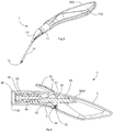
Fig. 1 is a perspective view from above of an insertion device or applicator of the invention with handle and stem parts separated, andFigs. 2 and3 are perspective views when these parts are connected; -
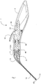
Figs. 4 to 7 are cross-sectional views of the handle part, the stem part, the stem tip, and the full device respectively; -
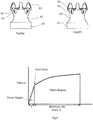
Figs. 8(a) to 8(f) are a series of diagrams illustrating deformation of a tympanostomy tube during insertion; -
Fig. 9 is a plot showing tube material deformation characteristics; -
Figs 10 and 11 are perspective views of a tympanostomy tube applicator of the invention in another embodiment; -
Fig. 12 is a side view of the applicator; -
Fig. 13 is a side view showing calibration of the device, andFig. 14 shows it in use; and -
Figs. 15 ,16 , and17 are enlarged side views of the head of the applicator in use deploying a tube. - Referring to
Figs. 1 to 9 a tympanostomy tube (sometimes referred to as a"grommet") applicator orinsertion device 1 comprises ahandle 2 and acartridge 3. Thehandle 2 has ahousing 5 shaped for ergonomic gripping, and a press-button 10 for operation. Also there is asocket 11 to receive aplug 12 of thecartridge 3. Thecartridge 3 has ahousing 13 which is bent to one side at its distal end, where it supports astem 14 terminating in atip 15. The stem 14of thecartridge 3 is flexible enough to deform to the desired shape during insertion, yet is resistant to compression. It includes a steel helical spring (Fig. 6, 14(a) within thestem 14 to allow flexure but good compression strength. - The cartridge is pre-assembled with a
tympanostomy tube 60, and so is for single use on one ear. Its connection to thehandle 2 is a twisting and pushing action which has the dual purpose of connecting thecartridge 3 to thehandle 2 and also compressing a spring, release of which will subsequently provide the force fortube 60 deformation in situ. The tube has a diameter of 2.5 mm as is typical for a tube of the type known as the "Shepard" type of tympanostomy tube. When thetube 60 has been inserted in one ear, the empty cartridge is removed and a second (loaded) cartridge is connected to the handle for the second ear if required (as is often the case). When this tube has been inserted into the second ear thehandle 2 is disposed of. However, thehandle 2 may be used if desired with additional loaded cartridges, for example for a further patient or upon premature activation of thetrigger 10. - The
handle 2 is made up of two ergonomic case moulded plastics halves 5(a) and 5(b). Thecartridge 3 is also made from components 13(a) and 13(b) which snap fit together during assembly. Thecartridge plug 12 has a tab 12(a) which mates with a slot 11(a) in thesocket 11. Once thecartridge plug 12 is fully inserted into thehandle socket 11 thecartridge 3 is rotated to lock it into place. On further rotation of thecartridge 3, the tab 12(a) locks into different mating parts of the slot 11(a), which provides the user with different variations of device setup.Fig. 3 shows thecartridge 3 set at 90° to thehandle 2. -
Fig. 4 shows a sectioned view of thehandle 2 in a resting configuration prior to connection of thecartridge 3. Thehandle button 10 hasratchets rotating drum 32. Apart 34 of thedrum 32 houses areturn spring 35 to provide upward bias to thebutton 10. Theratchets slider 40 which has opposingratchet teeth compression component 45 is mated coaxially to theslider 40 and both are assembled within acompression spring 46. Arubber ring 50 is housed within thecompression component 45 to provide damping during use, and there is a complementary damper sleeve 50(a) at the opposite (right side as viewed inFig. 4 ) end of theslider 40. As shown by this drawing theslider 40 is in two parts for manufacturing purposes, however, it may alternatively be moulded as an integral component.. There is areturn spring 49 for theslider 40. - Referring to
Figs. 5 and 6 , thecartridge 3 has amyringotomy knife 50 the distal end of which has asharp tip 52 for cutting through the tympanic membrane. Behind thetip 52 there is asurface 53 which is curved and narrows towards the proximal side, for use in deforming thetube 60 as described in more detail below. Immediately proximal to themyringotomy knife tip 52 there is atympanostomy tube 60 in a collapsed state. Themyringotomy knife 50 has a contouredsurface 53 which is configured to deform thetympanostomy tube 60 during deployment by expanding it from within. Themyringotomy knife 50 is connected to apuller component 51 via aflexible shaft 56 which trains through thestem 14. Abent feature 55 at the proximal end ensures that it stays in contact with thepull component 51 throughout deployment. Thepull component 51 connects with theslider component 40 within thehandle 2 when thecartridge 3 is connected to thehandle 2. - The distal end of the
stem 14 has alip 57 fitting laterally against and extending around almost the full circumference of the side of atube 60. In addition to helping to secure thetube 60 this also widens the stem end so that it acts as a stop to prevent unintentional excessive insertion, and also assists with location of theknife tip 52. - As shown most clearly in
Figs. 8(a) to 8(f) thetube 60 has a proximal (or "outer")pre-formed flange 61, acentral ventilation duct 62, and a distal (or "inner")flange 63 withslots 64. Theflange 63 has a diameter which is smaller than that of theproximal flange 61 by about 30% to 40%. There are also lead-inguide members 65 in the form of fingers extending generally axially from thedistal flange 63. There is oneslot 64 between eachguide member 65. Theslots 64 are grooves which do not penetrate for the full depth of the wall of thetube 60. In general their depth is in the range of about 20% to 90% of the wall depth, and preferably about 80%. - As is clear from
Fig. 8 thetube 60 as provided in thecartridge 3 already has a distal flange (63), however as noted above this has a diameter less than that of theproximal flange 61. However, thedistal flange 63 does not present a problem for insertion through the TM because of the action of theguide members 65. The latter have external surfaces which are tapered with a radial component which is inward and so allow streamlined insertion through the cut which has been made by theknife tip 52. - In use, as described above the surgeon connects the
cartridge 3 to the handle by engaging theplug 12 in thesocket 11 and rotating and pushing thecartridge 3 so that it is fully engaged and at the same time compresses thespring 46 so that it is loaded. The surgeon then moves thestem 14 through the ear canal and punctures the tympanic membrane using themyringotomy knife tip 52. Continued movement pushes through until theinner flange 63 and theouter flange 61 are on opposite sides of the tympanic membrane. Thelip 57 helps to prevent the surgeon from pushing thestem 14 too far into the middle ear; this feature acting as a backstop. To deform thetympanostomy tube 60, the surgeon merely presses thehandle button 10. This causes the mechanical advantage within thehandle 2 to pull on theslider component 51. This in turn pulls thedistal tip 52 of themyringotomy knife 50 through thetympanostomy tube 60, causing thetympanostomy tube 60 to deform and release from thedevice 1. This movement is shown inFigs. 8(a) to 8(f) . -
Fig. 7 shows thecartridge 3 assembled into thehandle 2 and thedevice 1 in the primed configuration prior totube 60 deployment. When thecartridge plug 12 is pushed into thehandle socket 11 this pushes on thecompression component 45 which in turn compresses thespring 46. - The user then locks the
cartridge 3 into thehandle 2 by rotating thecartridge 3, causing the tab 12(a) to lock into place. When the user pushes thebutton 10 this rotates thebutton drum 32 which also pushes against thespring 35. This disengages the drum ratchets 30 and 31 from theslider ratchet slider 40 to move under the force of thecompression spring 46 which in turn actuates thecartridge slider component 51 which is connected to themyringotomy knife 50. Themyringotomy knife tip 52 deforms thetympanostomy tube 60 and releases it from thecartridge 3. The speed at which themyringotomy knife tip 52 retracts through thetympanostomy tube 60 can be tuned by varying the stiffness of thecompression spring 46. - To reset the system to the resting configuration the user rotates the
cartridge 3 from its locked position within thehandle 2 and removes thecartridge 3. This releases thecompression component 45 and thereturn spring 49 resets all components to the initial position shown inFig. 4 . - In more detail,
Fig. 8 shows five steps of themyringotomy knife tip 52 deforming thetympanostomy tube 60, after it has been located with the assistance of theguides 65. As theproximal surface 53 of themyringotomy knife tip 52 contacts thetympanostomy tube 60, the surface's angle and slight concave shape causes thetympanostomy tube 60 to both expand radially and compress axially. Thetympanostomy tube 60relief slots 64 on theinner flange 63 allow thetympanostomy tube 60 to deform to the correct shape. Theinner flange 63 only increases in diameter by about 20% to 60%, and preferably in the range of 25% to 40%, however this is sufficient for adequate placement of thetube 60. It will be appreciated that the action of pulling through the tip only needs to achieve a limited, gradual and therefore predictable deformation of thetube 60. The tube's distal (inner) end only needs to turn through about 40° to reach the point of having the same diameter as the proximal flange. - The mechanical stress strain characteristics of the material used in the
tympanostomy tube 60 is advantageous to its correct function and deployment. The ideal material has a low elongation at the material yield point relative to its total elongation during plastic deformation. The plastic region of the stress strain curve would be at a minimum 50 times the elastic region of the stress strain curve with respect to material elongation. This relationship is shown inFig. 9 . - The
tube 60 is suitable for the surgical application of temporarily ventilating the ear for a period of about 9 months, and the general type is typically referred to as the "Shepard" type. However, the tympanostomy tube may in other embodiments be of a different shape such as those known widely as the "Paperella" tube, or alternatively as the "Reuter Bobbin" tube. Where the shape is for a permanent insertion the type known as the "T-Tube" may be used. These know shapes are the final outline shapes after deformation. - It will be appreciated from
Fig. 8 that, in addition to thedistal flange 63 expanding to its permanent shape, theguide members 65 change gradually from an orientation with an inward radial component (Fig. 8(a) ) to having an outward radial component (Figs. 8(b) and 8(c) ), and then back again to the inward direction (Figs. 8(d) to 8(f) ). Theguide members 65 hence play a role duringtube 60 expansion, namely helping to retain the correct tube position by exaggerating the inner flange temporarily as thetip 52 is retracted. It is envisaged that in other embodiments, theguide members 65 will be configured to be splayed out after tube deformation, thereby permanently enlarging the distal flange. - It will also be appreciated that the
device 1 makes the surgical task of tube insertion simpler, with less room for error. The spring for retraction is automatically loaded by the single action of twisting the cartridge onto the handle, and so this can not be inadvertently omitted. Also, thedevice 1 more importantly allows the surgeon to locate accurately the tube and deform it in situ with little risk of movement during deformation because the only action required is pressing thebutton 10 to release the pre-loaded spring for retraction. - Referring to
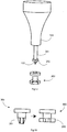
Figs. 10 to 17 atube applicator 100 comprises ahousing 102 arranged for single-handed grip, and a stem orhead 103 with aguide collar 104. The head is arranged for head rotation about an axis through thehousing 102. Aguide collar 104 surrounds thehead 103. There aretriggers collar adjustment button 112. Anendoscope 130 can be trained through aholder 131 and terminate in a lens 120 in thehead 103, as shown inFigs. 12 to 14 . - The
head 103 further comprises aninsertion assembly 200 having a sleeve-shapedstem 201, ashoulder 202. A rod (not shown) extends through thestem 201 and terminates in an inverted pyramid-shapedtip 122. Thetip 122 has an upper face on which there is aballoon 204 and atube 203 in a collapsed configuration. - The
head 103 at the distal end of the device is indexable with rotation about an axis extending through thehousing 102, with an allowed 180° rotation so that it may be used by either left or right-handed users. It has a cylindrical body portion, which can enter the patient's ear canal. The guide collar 4 can adjust the distance between the tip of the cylindrical body and the tympanic membrane. - There is a channel within the device to accept a
standard endoscope 130. This is formed by theendoscope guide 131 and thehead 103. Theendoscope 130 is pushed through the channel by the user until its lens 120 arrives at the tip of thehead 103.Fig. 12 shows a detailed view of the head cylindrical body, it shows the distal end 120 of theendoscope 130 and the pyramid-shapedmyringotomy blade tip 122 which is housed within thehead 103. - Prior to operation of the device, the endoscope is calibrated and focused using a
focus calibration jig 150, shown inFig. 13 . Thejig 150 comprises atop flange 151 connected to abottom flange 151 by aweb 153. Calibration is done by placing the tip of thehead 103 in a hole in thetop flange 151 of the jig 150.The endoscope is manipulated and focused until a target provided by the top surface of thelower flange 152 is in sharp focus on the video screen of theendoscope 130. This step is to ensure that the focal length of theendoscope 130 is at a fixed distance 'X' from the tip of the cylindrical body. - In use, the
trigger 111 is operated to cause theinsertion assembly 200 to extend from thehead 103. Thecollapsed tube 203 comprises a proximal flange 203(a), and a shank 203(b) with slits 203(d). - The clinician's index and middle fingers are placed on both of the
triggers button 112, and the ring and small fingers are free to rest on the patient's face to detect any movement during the procedure. The patient is typically a child. - As shown in
Fig. 14 , the device is placed into a patient's ear. The clinician will adjust theguide collar 104 by pressing thebutton 112. This will alter the distance between the tip of thehead 103 and the tympanic membrane. Once the tympanic membrane is in sharp focus the distance between the tip of thehead 103 and the tympanic membrane is at a constant distance 'X'. Once the clinician locates the anterior inferior quadrant of the tympanic membrane they will actuate thetrigger 111 to extend thetube insertion assembly 200, shown inFig. 15 , from its sheathed position within thehead 103. Thetube insertion assembly 200 will penetrate the tympanic membrane through the cutting action of themyringotomy tip 122 until part of thecollapsed tube 203 extends through the membrane. The proximal flange 203(a) of thetube 203 will help to prevent penetration too far into the middle ear. Then, actuation of thetrigger 110, as shown inFig. 16 , will expand theballoon 204 which is under thetube 203. This balloon inflation, will convert the tube shank 203(b) into a distal flange 203(c). This is because the shank 203(b) is of a material which deforms easily. In other embodiments the centre channel of the tube is also formed to its final state during the procedure. The action of balloon expansion is similar to that of retracting theknife tip 52 in thedevice 1, force is applied from within to expand the tube to provide the final shape with two flanges, one on each side of the TM. This radial expansion is a reliable and consistent way of deforming the original, collapsed, tube. We believe that it is much more effective than the prior approach of axially clamping the tube between stops. - The clinician now releases the
trigger 110 to deflate the balloon, and releases thetrigger 111 to retract the deflatedballoon 204 and thetip 122 through the formedtube 203, as shown inFig. 17 . On retraction the rod, which terminates in an inverted pyramid-shapedtip 122 and holds theballoon 204, will initially retract into theshaft 201. This will aid in ejection of thetube 203 by pushing it against the shoulder 202.Further release of thetrigger 111 causes thetube inserter assembly 200 to return into the cylindrical body. Thehead 103 is then removed from the patient's ear canal. - The action of the balloon is very effective at expanding the tube from within, as it is for other medical technologies such as stent deployment. On the other hand, in the embodiment of
Figs. 1 to 9 the role of the expansion balloon of expanding the tube from within is performed by a non-inflatable feature which is pulled through the collapsed tube using the trigger. This expands the tube to its final, unstressed, state. Once the curved feature has been pulled through the tube, it releases from the tube and the tube remains in the patient's tympanic membrane. The feature may be of a different shape such as spherical, and its shape may not be curved in side view, for example conical. - The tympanostomy tube may be made from a metal such as stainless steel or titanium, any of a range of biocompatible plastics such as fluoropolymers (PTFE, PFA, or ETFE), FEP Silicon, HDPE, or a shape memory plastic/metal such as PEEK/Nitinol. The tympanostomy tube in its collapsed state has features present in order to aid in the deployment of the tube. The tympanostomy tube could also have a conical profile (
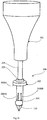
item 300,conical shank 301 as shown inFig. 18 ) along its axis so that when the initial myringotomy is made, further actuation of the tube inserter assembly would dilate the myringotomy in the membrane. Also, thedevice 1 may have a speculum and endoscope arrangement, and thejig 150 may also be used. - The invention is not limited to the embodiments described but may be varied in construction and detail within the scope of the claims. For example, the tympanostomy tube may be of any other known overall outline shape, as set out above. Also, the spring mechanism in the handle may have a spring with is extended to load it rather than being compressed.
Claims (15)
- A tympanostomy tube applicator (1, 100) comprising:a hand-held housing (2);a stem (14) extending from the housing and having a shape arranged for engagement in the ear canal; anda tympanostomy tube inserter (50);wherein the housing includes at least one user actuator (10, 110, 111, 112) for operation of the inserter;wherein the inserter (50, 200) comprises a rod (56) having a tip (52, 122) to pierce a patient's tympanic membrane and to support a collapsed tympanostomy tube (60, 203) through the membrane where it is pierced; andcharacterized in that, the inserter is adapted to press the collapsed tympanostomy tube from within at the distal end at least to expand from within said distal end (63, 203(b)) to provide in situ a distal flange (63, 203(c)) in the tympanostomy tube.
- A tympanostomy tube applicator as claimed in claim 1, wherein the inserter comprises a non-inflatable feature (52) adapted to be pulled through the collapsed tube to expand the tube.
- A tympanostomy tube applicator as claimed in claim 2, wherein said feature has a curved surface (53) for engagement with the tube (60) to expand it as the feature is pulled through,
wherein said surface (53) is on a proximal side of the feature (52) and is curved and narrows towards the proximal direction. - A tympanostomy tube applicator as claimed in any preceding claim, wherein the inserter comprises a shoulder (57, 202) to act as a proximal stop for the tympanostomy tube (203) during expansion of the tympanostomy tube (60, 203).
- A tympanostomy tube applicator as claimed in any preceding claim, wherein the applicator comprises a handle (2) with the actuator (10), and a cartridge (3) with the stem, and wherein the cartridge is being releasably connected to the handle.
- A tympanostomy tube applicator as claimed in claim 5, wherein the cartridge includes a distal part of the inserter which is adapted to connect with a proximal part of the inserter within the handle when the cartridge is connected to the handle, and wherein the inserter comprises a non-inflatable feature (52) adapted to be pulled through the collapsed tube to expand the tube, the inserter comprises a spring mechanism to pull the feature (52) through the tube, the cartridge is adapted to load the spring mechanism as it is connected to the handle, and the actuator is adapted to release the spring mechanism to pull the feature, and wherein the cartridge (3) is adapted to be connected to the handle (2) in a rotational and translational action, said action causing the spring mechanism to load, and wherein a plug (12) in the handle or the cartridge engages in a socket (11) in the other of the handle or the cartridge, and inter-engaging features cause a spring (46) of the spring mechanism to be loaded as the cartridge is connected to the handle.
- A tympanostomy tube applicator as claimed in any preceding claim, wherein the actuator comprises a single button (10) protruding from the housing.
- A tympanostomy tube applicator as claimed in either of claims 6 or 7, wherein the cartridge is pre-loaded with the tube (60) and the tube is non-removable except by operation of the inserter.
- A tympanostomy tube applicator as claimed in claims 1 or 4 to 8, wherein the inserter comprises a balloon (204) and means to inflate the balloon to expand the collapsed tube (203).
- A tympanostomy tube applicator as claimed in any preceding claim, wherein the stem is in the form of a speculum and includes a channel for an endoscope (130) arranged alongside the inserter (200), and wherein the housing has an endoscope guide (131) along a side of the housing, and further comprising a jig (150) for calibration of focal point of the endoscope (130) to a known distance before insertion, and wherein the jig (150) comprises a flange (151) for engagement with the head and a flange (152) for providing a visible plane at a known focusing distance.
- A tympanostomy tube applicator as claimed in any preceding claim, wherein the applicator further comprises a guide collar (57, 104) for the head, said guide collar being configured to engage a patient's ear proximally of the ear canal, and wherein the applicator further comprises an adjustment mechanism (112) for adjusting longitudinal position of the guide collar (104) with respect to the head (103).
- A tympanostomy tube (60, 203) comprising a proximal flange (61, 203(a)) and a shank (62, 203(b)) configured to expand with application of force from within said shank to form in situ a distal flange (63, 203(c)) and a central duct portion (62), and wherein the shank (65, 201) is tapered at a distal end with a curved external surface narrowing in the distal direction.
- A tympanostomy tube as claimed in claim 12, wherein the shank forms an initial distal flange (63), and said initial distal flange has slits or slots (64) to facilitate expansion.
- A tympanostomy tube as claimed in claims 12 or 13, wherein the tapered distal end comprises circumferentially spaced-apart guide members (65, 301).
- A tympanostomy tube as claimed in any of claims 12 to 14, wherein the tube (60) is of a material having a plastic region in a stress vs strain curve so that force applied causes it to become plastic and permanently deform with expansion of the distal end of the shank to an extent in the range of 20% to 60%.
Applications Claiming Priority (2)
| Application Number | Priority Date | Filing Date | Title |
|---|---|---|---|
| US201261726660P | 2012-11-15 | 2012-11-15 | |
| PCT/EP2013/073016 WO2014075949A1 (en) | 2012-11-15 | 2013-11-05 | Tympanostomy tube and insertion device |
Publications (2)
| Publication Number | Publication Date |
|---|---|
| EP2919729A1 EP2919729A1 (en) | 2015-09-23 |
| EP2919729B1 true EP2919729B1 (en) | 2017-05-31 |
Family
ID=49546401
Family Applications (1)
| Application Number | Title | Priority Date | Filing Date |
|---|---|---|---|
| EP13786476.5A Active EP2919729B1 (en) | 2012-11-15 | 2013-11-05 | Tympanostomy tube and insertion device |
Country Status (11)
| Country | Link |
|---|---|
| US (2) | US10016303B2 (en) |
| EP (1) | EP2919729B1 (en) |
| JP (1) | JP6490586B2 (en) |
| KR (1) | KR102016577B1 (en) |
| CN (1) | CN104797220B (en) |
| AU (1) | AU2013347073B2 (en) |
| CA (1) | CA2890730C (en) |
| DK (1) | DK2919729T3 (en) |
| ES (1) | ES2634322T3 (en) |
| IL (1) | IL238676B (en) |
| WO (1) | WO2014075949A1 (en) |
Families Citing this family (30)
| Publication number | Priority date | Publication date | Assignee | Title |
|---|---|---|---|---|
| US6770080B2 (en) | 2001-04-26 | 2004-08-03 | Fenestra Medical, Inc. | Mechanically registered videoscopic myringotomy/tympanostomy tube placement system |
| US9387124B2 (en) | 2007-04-19 | 2016-07-12 | Tusker Medical, Inc. | Disposable iontophoresis system and tympanic membrane pain inhibition method |
| US9539146B2 (en) | 2009-07-15 | 2017-01-10 | Tusker Medical, Inc. | Trigger assembly for tympanostomy tube delivery device |
| US9770366B2 (en) | 2009-07-15 | 2017-09-26 | Tusker Medical, Inc. | Tympanic membrane pressure equalization tube delivery system |
| US11213431B2 (en) * | 2012-07-05 | 2022-01-04 | Ear Tech, LLC | Nitinol tympanostomy tube |
| EP2919729B1 (en) * | 2012-11-15 | 2017-05-31 | Cork Institute Of Technology | Tympanostomy tube and insertion device |
| US9320652B2 (en) | 2013-03-14 | 2016-04-26 | Tusker Medical, Inc. | Features to improve and sense tympanic membrane apposition by tympanostomy tube delivery instrument |
| US9681891B2 (en) | 2013-03-14 | 2017-06-20 | Tusker Medical, Inc. | Tympanostomy tube delivery device with cutting dilator |
| US20160038341A1 (en) | 2014-08-08 | 2016-02-11 | Acclarent, Inc. | Tympanostomy tube delivery device with elastomeric brake |
| US10195086B2 (en) | 2014-08-11 | 2019-02-05 | Tusker Medical, Inc. | Tympanostomy tube delivery device with rotatable |
| US9833360B2 (en) * | 2014-08-12 | 2017-12-05 | Tusker Medical, Inc. | Tympanostomy tube delivery device with replaceable shaft portion |
| US9833359B2 (en) | 2014-08-12 | 2017-12-05 | Tusker Medical, Inc. | Tympanostomy tube delivery device with cutter force clutch |
| US10639200B2 (en) * | 2016-03-22 | 2020-05-05 | Gyrus Acmi, Inc. | Myringotomy tool with multiple tool heads |
| WO2018046598A1 (en) | 2016-09-08 | 2018-03-15 | Aventamed Designated Activity Company | A tympanostomy tube and placement device |
| WO2019017721A1 (en) * | 2017-07-21 | 2019-01-24 | 심민보 | Tip for intra-tympanic injection |
| WO2019066097A1 (en) * | 2017-09-26 | 2019-04-04 | 연세대학교 원주산학협력단 | Otitis media treatment instrument |
| WO2019157310A1 (en) * | 2018-02-08 | 2019-08-15 | Ear Tech, LLC | Nitinol tympanostomy tube |
| GB2585284B (en) * | 2018-02-27 | 2022-07-13 | Nextremity Solutions Inc | Disposable handle for medical instruments |
| DK3593772T3 (en) | 2018-07-13 | 2021-03-08 | Earbreeze Gmbh | DEVICE FOR AN APPARATUS FOR PRODUCING AN AIR FLOW OR FOR DELIVERING A FLUID IN THE OUTER EARROW AND THE EAR DRYING APPARATUS WITH THE DEVICE |
| US11684501B2 (en) | 2019-01-14 | 2023-06-27 | Cook Medical Technologies Llc | Multipurpose handle |
| CN114828793B (en) | 2019-11-01 | 2025-11-21 | 阿文塔米德指定活动公司 | Tympanic membrane pore-forming tube |
| US20220387223A1 (en) | 2019-11-01 | 2022-12-08 | Aventamed Designated Activity Company | A tympanic membrane therapeutic device |
| WO2021150858A1 (en) * | 2020-01-24 | 2021-07-29 | Spiral Therapeutics Inc. | Minimally-invasive tools and methods for accessing the middle and inner ear through the tympanic membrane |
| US11116668B1 (en) | 2020-05-04 | 2021-09-14 | Roger D. Haring | Cross-flange tympanostomy tube |
| US12280201B2 (en) | 2020-05-29 | 2025-04-22 | University Industry Foundation, Yonsei University Wonju Campus | Otitis media treatment instrument |
| US12478508B2 (en) * | 2020-12-31 | 2025-11-25 | Preceptis Medical, Inc. | Tube deploying system |
| CA3204009A1 (en) * | 2020-12-31 | 2022-07-07 | Rudolf Andreas Deibel | A tube deploying system |
| KR102531208B1 (en) * | 2021-02-23 | 2023-05-11 | 원텍 주식회사 | Apparatus of low level laser |
| US12544270B2 (en) | 2022-04-14 | 2026-02-10 | Preceptis Medical, Inc. | Ventilation tubes |
| WO2024192056A1 (en) * | 2023-03-13 | 2024-09-19 | Ear Tech, LLC | Tympanostomy tube insertion device |
Family Cites Families (18)
| Publication number | Priority date | Publication date | Assignee | Title |
|---|---|---|---|---|
| JPS5623606B2 (en) * | 1972-11-07 | 1981-06-01 | ||
| US3948271A (en) * | 1972-11-07 | 1976-04-06 | Taichiro Akiyama | Drain for the eardrum and apparatus for introducing the same |
| US4766886A (en) * | 1985-05-17 | 1988-08-30 | Juhn Steven K | Method and apparatus for viewing and collecting specimens |
| US5053040A (en) * | 1989-11-09 | 1991-10-01 | Goldsmith Iii Manning M | Method of performing a myringotomy |
| US5496329A (en) * | 1993-09-08 | 1996-03-05 | Alpha Surgical, Inc. | Method and apparatus for implanting a medical ventilation tube |
| US20030070676A1 (en) * | 1999-08-05 | 2003-04-17 | Cooper Joel D. | Conduits having distal cage structure for maintaining collateral channels in tissue and related methods |
| US20050060044A1 (en) * | 1999-08-05 | 2005-03-17 | Ed Roschak | Methods and devices for maintaining patency of surgically created channels in a body organ |
| US7115136B2 (en) * | 2001-06-20 | 2006-10-03 | Park Medical Llc | Anastomotic device |
| US20040204759A1 (en) * | 2001-12-28 | 2004-10-14 | Eric Blom | Prosthesis with foldable flange |
| US9387124B2 (en) * | 2007-04-19 | 2016-07-12 | Tusker Medical, Inc. | Disposable iontophoresis system and tympanic membrane pain inhibition method |
| US20090099573A1 (en) * | 2007-10-10 | 2009-04-16 | Donald Gonzales | Apparatus and Method for Treating Eustachian Tube Dysfunction |
| EP2252237B1 (en) * | 2008-02-20 | 2020-07-22 | Preceptis Medical, Inc. | Insertion system |
| US8945142B2 (en) * | 2008-08-27 | 2015-02-03 | Cook Medical Technologies Llc | Delivery system for implanting nasal ventilation tube |
| DK3329888T3 (en) * | 2009-07-15 | 2019-09-23 | Tusker Medical Inc | SYSTEM FOR INTRODUCING THE DRUM BRAKE COMBATING PIPES |
| US8998985B2 (en) * | 2011-07-25 | 2015-04-07 | Rainbow Medical Ltd. | Sinus stent |
| US9011363B2 (en) * | 2012-04-10 | 2015-04-21 | Acclarent, Inc. | Tympanic membrane pressure equalization tube |
| US9370448B2 (en) * | 2012-06-15 | 2016-06-21 | Preceptis Medical, Inc. | Insertion system for deploying a ventilation device |
| EP2919729B1 (en) * | 2012-11-15 | 2017-05-31 | Cork Institute Of Technology | Tympanostomy tube and insertion device |
-
2013
- 2013-11-05 EP EP13786476.5A patent/EP2919729B1/en active Active
- 2013-11-05 CA CA2890730A patent/CA2890730C/en active Active
- 2013-11-05 CN CN201380059545.3A patent/CN104797220B/en active Active
- 2013-11-05 JP JP2015542213A patent/JP6490586B2/en active Active
- 2013-11-05 AU AU2013347073A patent/AU2013347073B2/en active Active
- 2013-11-05 US US14/441,145 patent/US10016303B2/en active Active
- 2013-11-05 ES ES13786476.5T patent/ES2634322T3/en active Active
- 2013-11-05 DK DK13786476.5T patent/DK2919729T3/en active
- 2013-11-05 KR KR1020157012466A patent/KR102016577B1/en active Active
- 2013-11-05 WO PCT/EP2013/073016 patent/WO2014075949A1/en not_active Ceased
-
2015
- 2015-05-07 IL IL238676A patent/IL238676B/en active IP Right Grant
-
2018
- 2018-05-16 US US15/981,655 patent/US10751219B2/en active Active
Also Published As
| Publication number | Publication date |
|---|---|
| CN104797220B (en) | 2018-02-13 |
| CN104797220A (en) | 2015-07-22 |
| KR20150095629A (en) | 2015-08-21 |
| IL238676A0 (en) | 2015-06-30 |
| WO2014075949A1 (en) | 2014-05-22 |
| CA2890730C (en) | 2019-12-31 |
| KR102016577B1 (en) | 2019-08-30 |
| US20150290040A1 (en) | 2015-10-15 |
| ES2634322T3 (en) | 2017-09-27 |
| AU2013347073B2 (en) | 2017-11-09 |
| WO2014075949A9 (en) | 2014-12-18 |
| AU2013347073A1 (en) | 2015-05-28 |
| US10016303B2 (en) | 2018-07-10 |
| JP6490586B2 (en) | 2019-03-27 |
| DK2919729T3 (en) | 2017-09-18 |
| US20180256400A1 (en) | 2018-09-13 |
| CA2890730A1 (en) | 2014-05-22 |
| IL238676B (en) | 2018-06-28 |
| EP2919729A1 (en) | 2015-09-23 |
| US10751219B2 (en) | 2020-08-25 |
| JP2016501060A (en) | 2016-01-18 |
Similar Documents
| Publication | Publication Date | Title |
|---|---|---|
| US10751219B2 (en) | Tympansostomy tube and insertion device | |
| US12507880B2 (en) | Devices and methods for providing surgical access | |
| US5643280A (en) | Integral myringotomy tube and inserter | |
| EP3474778B1 (en) | System and method for crimping a prosthetic valve | |
| EP2649972B1 (en) | Tympanostomy tube delivery system | |
| EP4512351B1 (en) | A placement device | |
| US20180098789A1 (en) | Devices and methods for providing surgical access | |
| US20090012552A1 (en) | Surgical Tool for Coring Precise Holes and Providing for Retrieval of Tissue | |
| JP2015515887A (en) | Apparatus and method for transcatheter heart valve delivery | |
| CN106456154A (en) | Two-piece knotless suture anchor | |
| AU2018231241A1 (en) | Devices and methods for providing surgical access | |
| US20150164695A1 (en) | Tympanic membrane pressure equalization tube delivery system | |
| US20230110173A1 (en) | Tympanostomy tube and placement device | |
| WO2018165367A1 (en) | Devices and methods for providing surgical access | |
| AU2013219180B2 (en) | Surgical tool for coring precise holes and providing for retrieval of tissue |
Legal Events
| Date | Code | Title | Description |
|---|---|---|---|
| PUAI | Public reference made under article 153(3) epc to a published international application that has entered the european phase |
Free format text: ORIGINAL CODE: 0009012 |
|
| 17P | Request for examination filed |
Effective date: 20150512 |
|
| AK | Designated contracting states |
Kind code of ref document: A1 Designated state(s): AL AT BE BG CH CY CZ DE DK EE ES FI FR GB GR HR HU IE IS IT LI LT LU LV MC MK MT NL NO PL PT RO RS SE SI SK SM TR |
|
| AX | Request for extension of the european patent |
Extension state: BA ME |
|
| DAX | Request for extension of the european patent (deleted) | ||
| 17Q | First examination report despatched |
Effective date: 20160622 |
|
| GRAP | Despatch of communication of intention to grant a patent |
Free format text: ORIGINAL CODE: EPIDOSNIGR1 |
|
| INTG | Intention to grant announced |
Effective date: 20170124 |
|
| GRAS | Grant fee paid |
Free format text: ORIGINAL CODE: EPIDOSNIGR3 |
|
| GRAA | (expected) grant |
Free format text: ORIGINAL CODE: 0009210 |
|
| AK | Designated contracting states |
Kind code of ref document: B1 Designated state(s): AL AT BE BG CH CY CZ DE DK EE ES FI FR GB GR HR HU IE IS IT LI LT LU LV MC MK MT NL NO PL PT RO RS SE SI SK SM TR |
|
| REG | Reference to a national code |
Ref country code: CH Ref legal event code: EP Ref country code: GB Ref legal event code: FG4D |
|
| REG | Reference to a national code |
Ref country code: AT Ref legal event code: REF Ref document number: 896766 Country of ref document: AT Kind code of ref document: T Effective date: 20170615 |
|
| REG | Reference to a national code |
Ref country code: IE Ref legal event code: FG4D |
|
| REG | Reference to a national code |
Ref country code: DE Ref legal event code: R096 Ref document number: 602013021782 Country of ref document: DE |
|
| REG | Reference to a national code |
Ref country code: CH Ref legal event code: NV Representative=s name: ISLER AND PEDRAZZINI AG, CH |
|
| REG | Reference to a national code |
Ref country code: NL Ref legal event code: FP |
|
| REG | Reference to a national code |
Ref country code: DK Ref legal event code: T3 Effective date: 20170912 |
|
| REG | Reference to a national code |
Ref country code: SE Ref legal event code: TRGR |
|
| REG | Reference to a national code |
Ref country code: NO Ref legal event code: T2 Effective date: 20170531 |
|
| REG | Reference to a national code |
Ref country code: ES Ref legal event code: FG2A Ref document number: 2634322 Country of ref document: ES Kind code of ref document: T3 Effective date: 20170927 |
|
| REG | Reference to a national code |
Ref country code: LT Ref legal event code: MG4D |
|
| REG | Reference to a national code |
Ref country code: AT Ref legal event code: MK05 Ref document number: 896766 Country of ref document: AT Kind code of ref document: T Effective date: 20170531 |
|
| PG25 | Lapsed in a contracting state [announced via postgrant information from national office to epo] |
Ref country code: GR Free format text: LAPSE BECAUSE OF FAILURE TO SUBMIT A TRANSLATION OF THE DESCRIPTION OR TO PAY THE FEE WITHIN THE PRESCRIBED TIME-LIMIT Effective date: 20170901 Ref country code: LT Free format text: LAPSE BECAUSE OF FAILURE TO SUBMIT A TRANSLATION OF THE DESCRIPTION OR TO PAY THE FEE WITHIN THE PRESCRIBED TIME-LIMIT Effective date: 20170531 Ref country code: FI Free format text: LAPSE BECAUSE OF FAILURE TO SUBMIT A TRANSLATION OF THE DESCRIPTION OR TO PAY THE FEE WITHIN THE PRESCRIBED TIME-LIMIT Effective date: 20170531 Ref country code: AT Free format text: LAPSE BECAUSE OF FAILURE TO SUBMIT A TRANSLATION OF THE DESCRIPTION OR TO PAY THE FEE WITHIN THE PRESCRIBED TIME-LIMIT Effective date: 20170531 Ref country code: HR Free format text: LAPSE BECAUSE OF FAILURE TO SUBMIT A TRANSLATION OF THE DESCRIPTION OR TO PAY THE FEE WITHIN THE PRESCRIBED TIME-LIMIT Effective date: 20170531 |
|
| REG | Reference to a national code |
Ref country code: FR Ref legal event code: PLFP Year of fee payment: 5 |
|
| PG25 | Lapsed in a contracting state [announced via postgrant information from national office to epo] |
Ref country code: RS Free format text: LAPSE BECAUSE OF FAILURE TO SUBMIT A TRANSLATION OF THE DESCRIPTION OR TO PAY THE FEE WITHIN THE PRESCRIBED TIME-LIMIT Effective date: 20170531 Ref country code: LV Free format text: LAPSE BECAUSE OF FAILURE TO SUBMIT A TRANSLATION OF THE DESCRIPTION OR TO PAY THE FEE WITHIN THE PRESCRIBED TIME-LIMIT Effective date: 20170531 Ref country code: IS Free format text: LAPSE BECAUSE OF FAILURE TO SUBMIT A TRANSLATION OF THE DESCRIPTION OR TO PAY THE FEE WITHIN THE PRESCRIBED TIME-LIMIT Effective date: 20170930 Ref country code: BG Free format text: LAPSE BECAUSE OF FAILURE TO SUBMIT A TRANSLATION OF THE DESCRIPTION OR TO PAY THE FEE WITHIN THE PRESCRIBED TIME-LIMIT Effective date: 20170831 |
|
| PG25 | Lapsed in a contracting state [announced via postgrant information from national office to epo] |
Ref country code: CZ Free format text: LAPSE BECAUSE OF FAILURE TO SUBMIT A TRANSLATION OF THE DESCRIPTION OR TO PAY THE FEE WITHIN THE PRESCRIBED TIME-LIMIT Effective date: 20170531 Ref country code: SK Free format text: LAPSE BECAUSE OF FAILURE TO SUBMIT A TRANSLATION OF THE DESCRIPTION OR TO PAY THE FEE WITHIN THE PRESCRIBED TIME-LIMIT Effective date: 20170531 Ref country code: EE Free format text: LAPSE BECAUSE OF FAILURE TO SUBMIT A TRANSLATION OF THE DESCRIPTION OR TO PAY THE FEE WITHIN THE PRESCRIBED TIME-LIMIT Effective date: 20170531 Ref country code: RO Free format text: LAPSE BECAUSE OF FAILURE TO SUBMIT A TRANSLATION OF THE DESCRIPTION OR TO PAY THE FEE WITHIN THE PRESCRIBED TIME-LIMIT Effective date: 20170531 |
|
| PG25 | Lapsed in a contracting state [announced via postgrant information from national office to epo] |
Ref country code: SM Free format text: LAPSE BECAUSE OF FAILURE TO SUBMIT A TRANSLATION OF THE DESCRIPTION OR TO PAY THE FEE WITHIN THE PRESCRIBED TIME-LIMIT Effective date: 20170531 Ref country code: PL Free format text: LAPSE BECAUSE OF FAILURE TO SUBMIT A TRANSLATION OF THE DESCRIPTION OR TO PAY THE FEE WITHIN THE PRESCRIBED TIME-LIMIT Effective date: 20170531 |
|
| REG | Reference to a national code |
Ref country code: DE Ref legal event code: R097 Ref document number: 602013021782 Country of ref document: DE |
|
| PLBE | No opposition filed within time limit |
Free format text: ORIGINAL CODE: 0009261 |
|
| STAA | Information on the status of an ep patent application or granted ep patent |
Free format text: STATUS: NO OPPOSITION FILED WITHIN TIME LIMIT |
|
| 26N | No opposition filed |
Effective date: 20180301 |
|
| PG25 | Lapsed in a contracting state [announced via postgrant information from national office to epo] |
Ref country code: SI Free format text: LAPSE BECAUSE OF FAILURE TO SUBMIT A TRANSLATION OF THE DESCRIPTION OR TO PAY THE FEE WITHIN THE PRESCRIBED TIME-LIMIT Effective date: 20170531 |
|
| PG25 | Lapsed in a contracting state [announced via postgrant information from national office to epo] |
Ref country code: MC Free format text: LAPSE BECAUSE OF FAILURE TO SUBMIT A TRANSLATION OF THE DESCRIPTION OR TO PAY THE FEE WITHIN THE PRESCRIBED TIME-LIMIT Effective date: 20170531 |
|
| PG25 | Lapsed in a contracting state [announced via postgrant information from national office to epo] |
Ref country code: LU Free format text: LAPSE BECAUSE OF NON-PAYMENT OF DUE FEES Effective date: 20171105 |
|
| REG | Reference to a national code |
Ref country code: FR Ref legal event code: PLFP Year of fee payment: 6 |
|
| PG25 | Lapsed in a contracting state [announced via postgrant information from national office to epo] |
Ref country code: MT Free format text: LAPSE BECAUSE OF NON-PAYMENT OF DUE FEES Effective date: 20171105 |
|
| PG25 | Lapsed in a contracting state [announced via postgrant information from national office to epo] |
Ref country code: HU Free format text: LAPSE BECAUSE OF FAILURE TO SUBMIT A TRANSLATION OF THE DESCRIPTION OR TO PAY THE FEE WITHIN THE PRESCRIBED TIME-LIMIT; INVALID AB INITIO Effective date: 20131105 |
|
| PG25 | Lapsed in a contracting state [announced via postgrant information from national office to epo] |
Ref country code: CY Free format text: LAPSE BECAUSE OF FAILURE TO SUBMIT A TRANSLATION OF THE DESCRIPTION OR TO PAY THE FEE WITHIN THE PRESCRIBED TIME-LIMIT Effective date: 20170531 |
|
| PG25 | Lapsed in a contracting state [announced via postgrant information from national office to epo] |
Ref country code: MK Free format text: LAPSE BECAUSE OF FAILURE TO SUBMIT A TRANSLATION OF THE DESCRIPTION OR TO PAY THE FEE WITHIN THE PRESCRIBED TIME-LIMIT Effective date: 20170531 |
|
| PG25 | Lapsed in a contracting state [announced via postgrant information from national office to epo] |
Ref country code: TR Free format text: LAPSE BECAUSE OF FAILURE TO SUBMIT A TRANSLATION OF THE DESCRIPTION OR TO PAY THE FEE WITHIN THE PRESCRIBED TIME-LIMIT Effective date: 20170531 |
|
| PG25 | Lapsed in a contracting state [announced via postgrant information from national office to epo] |
Ref country code: PT Free format text: LAPSE BECAUSE OF FAILURE TO SUBMIT A TRANSLATION OF THE DESCRIPTION OR TO PAY THE FEE WITHIN THE PRESCRIBED TIME-LIMIT Effective date: 20170531 |
|
| PG25 | Lapsed in a contracting state [announced via postgrant information from national office to epo] |
Ref country code: AL Free format text: LAPSE BECAUSE OF FAILURE TO SUBMIT A TRANSLATION OF THE DESCRIPTION OR TO PAY THE FEE WITHIN THE PRESCRIBED TIME-LIMIT Effective date: 20170531 |
|
| REG | Reference to a national code |
Ref country code: DE Ref legal event code: R081 Ref document number: 602013021782 Country of ref document: DE Owner name: MUNSTER TECHNOLOGICAL UNIVERSITY, BISHOPSTOWN, IE Free format text: FORMER OWNER: CORK INSTITUTE OF TECHNOLOGY, BISHOPSTOWN, COUNTY CORK, IE |
|
| REG | Reference to a national code |
Ref country code: NO Ref legal event code: CHAD Owner name: MUNSTER TECHNOLOGICAL UNIVERSITY, IE |
|
| REG | Reference to a national code |
Ref country code: GB Ref legal event code: 732E Free format text: REGISTERED BETWEEN 20220120 AND 20220126 |
|
| REG | Reference to a national code |
Ref country code: NL Ref legal event code: HC Owner name: MUNSTER TECHNOLOGICAL UNIVERSITY; IE Free format text: DETAILS ASSIGNMENT: CHANGE OF OWNER(S), CHANGE OF OWNER(S) NAME; FORMER OWNER NAME: CORK INSTITUTE OF TECHNOLOGY Effective date: 20220113 |
|
| P01 | Opt-out of the competence of the unified patent court (upc) registered |
Effective date: 20230427 |
|
| REG | Reference to a national code |
Ref country code: CH Ref legal event code: U11 Free format text: ST27 STATUS EVENT CODE: U-0-0-U10-U11 (AS PROVIDED BY THE NATIONAL OFFICE) Effective date: 20251201 |
|
| PGFP | Annual fee paid to national office [announced via postgrant information from national office to epo] |
Ref country code: NL Payment date: 20251124 Year of fee payment: 13 |
|
| PGFP | Annual fee paid to national office [announced via postgrant information from national office to epo] |
Ref country code: DE Payment date: 20251126 Year of fee payment: 13 |
|
| PGFP | Annual fee paid to national office [announced via postgrant information from national office to epo] |
Ref country code: GB Payment date: 20251125 Year of fee payment: 13 |
|
| PGFP | Annual fee paid to national office [announced via postgrant information from national office to epo] |
Ref country code: NO Payment date: 20251120 Year of fee payment: 13 |
|
| PGFP | Annual fee paid to national office [announced via postgrant information from national office to epo] |
Ref country code: IT Payment date: 20251121 Year of fee payment: 13 Ref country code: DK Payment date: 20251124 Year of fee payment: 13 |
|
| PGFP | Annual fee paid to national office [announced via postgrant information from national office to epo] |
Ref country code: FR Payment date: 20251124 Year of fee payment: 13 |
|
| PGFP | Annual fee paid to national office [announced via postgrant information from national office to epo] |
Ref country code: BE Payment date: 20251124 Year of fee payment: 13 |
|
| PGFP | Annual fee paid to national office [announced via postgrant information from national office to epo] |
Ref country code: CH Payment date: 20251201 Year of fee payment: 13 Ref country code: SE Payment date: 20251124 Year of fee payment: 13 |
|
| PGFP | Annual fee paid to national office [announced via postgrant information from national office to epo] |
Ref country code: IE Payment date: 20251118 Year of fee payment: 13 |
|
| PGFP | Annual fee paid to national office [announced via postgrant information from national office to epo] |
Ref country code: ES Payment date: 20251209 Year of fee payment: 13 |