EP2918752A1 - Outer wall membrane construction method and outer wall membrane structure for chimney stacks - Google Patents
Outer wall membrane construction method and outer wall membrane structure for chimney stacks Download PDFInfo
- Publication number
- EP2918752A1 EP2918752A1 EP12886498.0A EP12886498A EP2918752A1 EP 2918752 A1 EP2918752 A1 EP 2918752A1 EP 12886498 A EP12886498 A EP 12886498A EP 2918752 A1 EP2918752 A1 EP 2918752A1
- Authority
- EP
- European Patent Office
- Prior art keywords
- membrane
- exterior
- members
- stack
- fixing
- Prior art date
- Legal status (The legal status is an assumption and is not a legal conclusion. Google has not performed a legal analysis and makes no representation as to the accuracy of the status listed.)
- Granted
Links
Images



Classifications
-
- E—FIXED CONSTRUCTIONS
- E04—BUILDING
- E04H—BUILDINGS OR LIKE STRUCTURES FOR PARTICULAR PURPOSES; SWIMMING OR SPLASH BATHS OR POOLS; MASTS; FENCING; TENTS OR CANOPIES, IN GENERAL
- E04H12/00—Towers; Masts or poles; Chimney stacks; Water-towers; Methods of erecting such structures
- E04H12/28—Chimney stacks, e.g. free-standing, or similar ducts
-
- E—FIXED CONSTRUCTIONS
- E04—BUILDING
- E04F—FINISHING WORK ON BUILDINGS, e.g. STAIRS, FLOORS
- E04F13/00—Coverings or linings, e.g. for walls or ceilings
- E04F13/002—Coverings or linings, e.g. for walls or ceilings made of webs, e.g. of fabrics, or wallpaper, used as coverings or linings
- E04F13/005—Stretched foil- or web-like elements attached with edge gripping devices
-
- E—FIXED CONSTRUCTIONS
- E04—BUILDING
- E04H—BUILDINGS OR LIKE STRUCTURES FOR PARTICULAR PURPOSES; SWIMMING OR SPLASH BATHS OR POOLS; MASTS; FENCING; TENTS OR CANOPIES, IN GENERAL
- E04H15/00—Tents or canopies, in general
- E04H15/32—Parts, components, construction details, accessories, interior equipment, specially adapted for tents, e.g. guy-line equipment, skirts, thresholds
- E04H15/64—Tent or canopy cover fastenings
- E04H15/642—Tent or canopy cover fastenings with covers held by elongated fixing members locking in longitudinal recesses of a frame
- E04H15/644—Tent or canopy cover fastenings with covers held by elongated fixing members locking in longitudinal recesses of a frame the fixing members being a beading
Definitions
- the present invention relates to an exterior wall membrane construction method in which a decorative exterior wall that surrounds a periphery of a stack has a membrane structure, instead of the conventional concrete structure, in order not to impair the scenery, and to an exterior wall membrane structure constructed with this method.
- a periphery of a stack constructed in cities and tourist destinations is often surrounded with a decorative exterior wall in order not to impair the scenery (See, for example, Patent Document 1).
- Such an exterior wall that surrounds the periphery of a stack is generally made of reinforced concrete, lightweight aerated concrete, prestressed concrete panels, and the like.
- the exterior wall is made of reinforced concrete, and the like, it is difficult to make a design that gives consideration to the environment, and, the construction period thereof is also as long as a year.
- the shape of the exterior wall that is made of reinforced concrete and the like is limited to standard shapes such as a rectangle, a circle, and a polygon.
- the exterior wall requires repair due to time-related deterioration, there is no way but to repair only the peripheral portions of the exterior wall as the industrial design applied to the exterior wall cannot be changed, and, the repair period is also long.
- Patent Document 1 Japanese Patent Application Laid-open No. H06-66051
- the issues that the present invention intends to solve are, when surrounding the periphery of a stack with an exterior wall of reinforced concrete or the like, that it is difficult to make a design that gives consideration to the environment, and, that the construction period is as long as a year.
- the shape of the exterior wall is limited to the standard shapes such as the rectangle, the circle, and the polygon.
- the exterior wall requires repair due to time-related deterioration, there is no way but to repair only the peripheral portions of the exterior wall as the industrial design applied to the exterior wall cannot be changed, and, the repair period is also long.
- a method of constructing an exterior wall membrane that surrounds a stack includes surrounding with a membrane member an exterior side of first steel members that are arranged around the stack to support the stack, or second steel members that are arranged on the first steel members, and then fixing a membrane member exterior edge that is an exterior edge of the membrane member and, if required, an appropriate position of the membrane member other than the membrane member exterior edge.
- an exterior wall membrane structure that surrounds a membrane member from an exterior side of first steel members that are arranged around the stack to support the stack, or second steel members that are arranged on the first steel members, and fixes a membrane member exterior edge that is an exterior edge of the membrane member and, if required, an appropriate position of the membrane member other than the membrane member exterior edge, can be constructed in a short time.
- the industrial design applied to the exterior wall can be easily changed when repairing the time-related deterioration of the exterior wall, and, this repair can be made in a short time.
- the foundation work can be reduced.
- the first steel members that support the stack also serve as the support members that support the membrane members, the construction period can be drastically shortened, and the construction cost can be drastically reduced.
- the construction work can be carried out from inside of the exterior wall membrane structure, the scaffold becomes unnecessary, and therefore, the construction period can be further shortened, and the construction cost can be further reduced.
- the second steel members in addition to the first steel members that support the stack, construction of structures with shapes having depressions become possible, making it possible to construct an exterior wall having a complex geometric shape that enhances the design.
- the present invention achieves the above object, that is, to present an exterior wall that surrounds the periphery of a stack, that can be designed by giving consideration to the environment, that can be constructed in a short time, and that can have a complex geometric shape that enhances the design, by constructing a membrane member, which is lightweight as compared to concrete, from inside.
- FIG. 1 to FIG. 7 Exemplary embodiments of the present invention are explained below while referring to FIG. 1 to FIG. 7 .
- FIG. 1 is a schematic diagram of a self-standing stack to which an exterior wall membrane structure according to the present invention has been applied.
- a self-standing stack is the one that is constructed directly on the ground.
- FIG. 2 is a schematic diagram of an integrated stack to which the exterior wall membrane structure according to the present invention has been applied.
- An integrated stack is the one that is coupled to an upper part of a building.
- reference number 1 represents stacks.
- two stacks 1 are arranged with a certain distance therebetween.
- Those two stacks 1 are supported by first steel members 2 (three in the example of FIG. 1 and four in the example of FIG. 2 ), and flooring members 3.
- the first steel members 2 are arranged around the stacks 1.
- the flooring members 3 are attached to the first steel members 2 at predetermined heights and in an appropriate number.
- the flooring members 3 are supported by beam members 4 that couple and fix the first steel members 2.
- the periphery of the stacks 1 is surrounded with membrane members 5 in order not to impair the scenery.
- the membrane members 5 are arranged so as to surround an exterior periphery of the three first steel members 2.
- the flooring members 3 are hexagonal and attached to the beam members 4 that couple and fix the first steel members 2.
- Rib members 11 are arranged so as to make a circumscribed circle from the three first steel members 2 and the flooring members 3. In a portion where the flooring members 3 are arranged, the membrane members 5 are arranged so as to surround the exterior periphery of the rib members 11.
- the membrane members 5 are arranged so as to surround an exterior periphery of the four first steel members 2.
- the flooring members 3 are quadrangular and attached to the beam members 4 that couple and fix the first steel members 2.
- the rib members 11 are arranged so as to make an internal portion of the building (excluding the left side in FIG. 2(b) to (d) ) a curved surface from the four first steel members 2 and the flooring members 3.
- the membrane members 5 are arranged so as to surround the exterior periphery of the rib members 11.
- the flooring members 3 arranged in an upper portion of the structure are trapezoidal, and those arranged in a middle portion and a leg portion are rectangular.
- Second steel members 6 are arranged so as to protrude out from a central portion of two opposing beam members 4, and the membrane members 5 are arranged so as to surround the tip portions of the second steel members 6.
- exterior edges of the adjacent membrane members 5, which surround the exterior periphery of the stacks 1 in this manner, are, for example, at the positions of the three first steel members 2, drawn toward the inner side of the structure and fixed to each other.
- three membrane members 5 are arranged in the circumferential direction of the structure.
- exterior edges of adjacent membrane members 5 are, at the positions of the second steel members 6, which protrude out from a central portion of two opposing beam members 4, drawn toward inner side of the structure and fixed to each other.
- two membrane members 5 are arranged in the circumferential direction of the structure.
- a fixing mechanism 7 shown in FIG. 3 includes a pair of crooked opposing nipping levers 7a.
- Each of the nipping levers 7a has a base end and a tip end. The tip ends of the nipping levers 7a approach or separate from each other when the nipping levers 7a swing with the base end as a pivot 7aa.
- a locking tool 7b that locks the exterior edge of the membrane member 5 is attached to each of the nipping levers 7a at a position that is toward the tip end relative to a central bent portion 7ab.
- the locking tool 7b has a hole 7ba and a slit 7bb from which the hole 7ba communicates to the outside.
- the exterior edge of the membrane member 5 is rolled and made into a closed loop and an edge rope is integrally inserted into the loop of the exterior edge. This exterior edge with the edge rope is then inserted into the hole 7ba via the slit 7bb from vertical cross-sectional direction.
- the locking tool 7b is fixed to the respective nipping lever 7a with a tension rod 12.
- a water sealing rubber 8 can be inserted between the tip ends of the nipping levers 7a when drawing the exterior edges of the membrane members 5 and fixing the exterior edges.
- the water sealing rubber 8 prevents entry of water inside the structure while the exterior edges of the membrane members 5 are being drawn and fixed.
- an inner membrane member 9 is arranged between opposing locking tools 7b to surely prevent the entry of water inside the structure after the exterior edges of the membrane members 5 are drawn and fixed.
- the nipping levers 7a and the swinging and fixing mechanism 7c together constitute the drawing member, and the locking tools 7b constitutes the fixing tool.
- the fixing mechanism 7 shown in FIG. 4 includes a pair of pipe members 7d arranged side by side with a gap d1 that allows insertion of the exterior edges of the membrane members 5.
- the exterior edges of the membrane members 5 that are inserted from the gap d1 between the pipe members 7d are then integrally fixed by using a tightening tool 7e.
- the tightening tool 7e includes a pair of membrane fixing plates 7ea that sandwich the exterior edges of the membrane members 5, and a fixing bolt 7eb and a nut 7ec that keep the membrane fixing plates 7ea together.
- the exterior edges of the membrane members 5 are integrally fixed to each other by tightening the nut 7ec.
- the exterior edges of the membrane members 5 can be integrally fixed to each other by using the locking tool 7b and the tension rod 12 instead of using the tightening tool 7e.
- the water sealing rubber 8 can be inserted in the gap d1 between the pipe members 7d from which the exterior edges of the membrane members 5 that are inserted when drawing the exterior edges of the membrane members 5 and fixing the exterior edges.
- the water sealing rubber 8 prevents entry of water inside the structure while the exterior edges of the membrane members 5 are being drawn and fixed.
- a reference number 10 represents the edge ropes that are integrated with the exterior edges of the membrane members 5. The exterior edge of the membrane member 5 is rolled and made into a closed loop by thermal welding and the like, and then an edge rope 10 is integrally inserted into the loop of the exterior edge.
- the pipe members 7d constitute the drawing member
- the tightening tool 7e constitutes the fixing tool.
- the fixing mechanism 7 shown in FIG. 5 includes a pair of pipe members 7f arranged with an interval d2 and attached to a tip portion of the first steel member 2 or the second steel member 6, tension rods 7g with base ends thereof attached to the first steel member 2 or the second steel member 6, and locking tools 7h attached to tip ends of the tension rods 7g.
- the exterior edges of the membrane members 5 are drawn by turning around the peripheral surfaces of the pipe members 7f and then fixed with the locking tools 7h.
- a water entry prevention membrane 7i that encloses the tip end of the first steel member 2 or the second steel member 6 can be arranged to prevent entry of water inside the structure while the exterior edges of the membrane members 5 are being drawn and fixed.
- One end of the water entry prevention membrane 7i is attached to the first steel member 2 or the second steel member 6, and the other end thereof is welded to the membrane member 5 by thermal welding and the like.
- the pair of pipe members 7f attached in a protruding manner to the tip portion of the first steel member 2 or the second steel member 6, and the pair of tension rods 7g attached to the first steel member 2 or the second steel member 6 constitute the drawing member, and the locking tool 7h constitutes the fixing tool.
- the exterior wall membrane structure according to the present invention includes surrounding the exterior peripheral portions of the first steel members 2 that support the stacks 1 with the membrane members 5 to form a structure that has the first steel members 2 at apices thereof.
- the exterior wall membrane structure according to the present invention includes surrounding the exterior peripheral portions of the first steel members 2 to support the stacks 1 and the second steel members 6 with the membrane members 5 to form a structure that has the first steel members 2 and the second steel members 6 at apices thereof. This work can be carried out from inside eliminating the need to construct a dedicated scaffold on the outside of the first steel members 2 and the second steel members 6.
- the exterior edges of the adjacent membrane members 5 are drawn from the outside to the inside of the structure at the positions of the three first steel members 2, and at the drawn location, those drawn exterior edges are fixed by using the fixing mechanism 7 shown in any one of FIG. 3 to FIG. 5 .
- the exterior edges of the adjacent membrane members 5 are drawn from the outside to the inside of the structure at the positions of the two steel members 6, and at the drawn location, those drawn exterior edges are fixed by using the fixing mechanism 7 shown in any one of FIG. 3 to FIG. 5 .
- the membrane member 5 that is lightweight as compared to concrete has been used, the foundation work can be reduced. Moreover, because the first steel members 2 that support the stacks 1 also serve as the support members that support the membrane members 5, the construction period can be drastically shortened, and the construction cost can also be drastically reduced.
- the scaffold becomes unnecessary, and therefore, the construction period can be further shortened, and the construction cost can be further reduced.
- shapes having depressions can be dealt with making it possible to construct an exterior wall having a complex geometric shape that enhances the design.
- the industrial design applied to the exterior wall can be easily changed when repairing the exterior wall, and, this repair can be made in a short time.
- the membrane member 5 used in the present invention possesses durability and thermal resistance necessary for the exterior wall of the stacks 1, the material of the membrane member 5 does not matter.
- glass fiber having a coating of fluororesin can be used for the membrane member 5.
- the exteriormost layer of the membrane member 5 is subjected to an anti-smudge treatment, such as coating a photocatalyst layer, then smudge due to time-related change reduces, and maintainability can be improved. Furthermore, if the membrane member 5 that allows passage of light is used, a fantastic environment can be produced in the night time by installing decorative lights on the inner side of the membrane member 5.
- the examples shown in FIG. 1 and FIG. 2 assume that a single piece of the membrane member 5 is used in the height direction; however, plural pieces of the membrane member 5 can be used in the height direction. Moreover, the membrane member 5 can be wound obliquely.
- the exterior wall membrane structure shown in FIG. 1 and FIG. 2 that uses the fixing mechanism 7 shown in FIG. 3 to FIG. 5 has substantially similar structure in the horizontal cross-section taken at any location from the base end to the tip end of the stack.
- FIG. 6 it is possible to construct an exterior wall membrane structure having an enhanced design in which the horizontal cross-sections taken at different locations from the base end to the tip end of the stack have different structures.
- the fixing mechanism 7 shown in FIG. 7 can be used.
- the fixing mechanism 7 shown in FIG. 7 includes a locking tool 7j, a U-shaped plate member 7k, and a bolt 7n and a nut 7o that fix the U-shaped plate member 7k to the locking tool 7j.
- the locking tool 7j includes a hole 7ja and a slit 7jb from which the hole 7ja communicates to the outside.
- An exterior edge of the membrane member 5 is rolled and made into a closed loop and the edge rope 10 is integrally inserted into this loop. This exterior edge of the membrane member 5 with the edge rope 10 is inserted into the hole 7ja via the slit 7jb from a vertical cross-sectional direction.
- Plural wires 7m are appropriately stretched around the stacks from the base end to the tip end thereof to form a predetermined horizontal cross-sectional shape, and the curved end of the U-shaped plate member 7k is engaged with one of the wires 7m.
- the wires 7m can be stretched from, for example, a support member located at an upper part of the stacks (the first steel members 2, the beam members 4, or the second steel members 6) to a support member located at a lower part of the stacks (a foundation of the stacks in case of the self-standing stack shown in FIG. 1 , or a support member arranged at an upper part of the building in case of the integrated stack shown in FIG. 2 ) .
- the exterior edges of the membrane members 5 can be fixed by simply stretching the wires 7m at predetermined positions without passing them through steel members.
- the exterior edges of the adjacent membrane members 5 (or separate membrane members attached to those exterior edges by welding) can be attached to a square member 7q that is attached to one of the locking tools 7j via an angle member 7p.
- This structure insulates the fixing parts from outside and prevents entry of water inside the structure.
- the fixing mechanism 7 shown in FIG. 7 allows fixing of the membrane member 5 at an appropriate position other than the exterior edge of the membrane member 5.
Landscapes
- Engineering & Computer Science (AREA)
- Architecture (AREA)
- Civil Engineering (AREA)
- Structural Engineering (AREA)
- Tents Or Canopies (AREA)
Abstract
Description
- The present invention relates to an exterior wall membrane construction method in which a decorative exterior wall that surrounds a periphery of a stack has a membrane structure, instead of the conventional concrete structure, in order not to impair the scenery, and to an exterior wall membrane structure constructed with this method.
- A periphery of a stack constructed in cities and tourist destinations is often surrounded with a decorative exterior wall in order not to impair the scenery (See, for example, Patent Document 1). Such an exterior wall that surrounds the periphery of a stack is generally made of reinforced concrete, lightweight aerated concrete, prestressed concrete panels, and the like.
- However, if the exterior wall is made of reinforced concrete, and the like, it is difficult to make a design that gives consideration to the environment, and, the construction period thereof is also as long as a year. Moreover, the shape of the exterior wall that is made of reinforced concrete and the like is limited to standard shapes such as a rectangle, a circle, and a polygon. Moreover, when the exterior wall requires repair due to time-related deterioration, there is no way but to repair only the peripheral portions of the exterior wall as the industrial design applied to the exterior wall cannot be changed, and, the repair period is also long.
- In the recent years, skeleton stacks in which steel louvers are arranged on an exterior surface thereof have been constructed. However, in the case of a skeleton stack, there is a problem that the steel louvers undergo steel corrosion and that the periphery of the stack cannot be divided into compartments.
- Patent Document 1: Japanese Patent Application Laid-open No.
H06-66051 - The issues that the present invention intends to solve are, when surrounding the periphery of a stack with an exterior wall of reinforced concrete or the like, that it is difficult to make a design that gives consideration to the environment, and, that the construction period is as long as a year. Moreover, the shape of the exterior wall is limited to the standard shapes such as the rectangle, the circle, and the polygon. Moreover, when the exterior wall requires repair due to time-related deterioration, there is no way but to repair only the peripheral portions of the exterior wall as the industrial design applied to the exterior wall cannot be changed, and, the repair period is also long.
- An object of the present invention is to present an exterior wall, which can be used to surround the periphery of a stack, that can be designed by giving consideration to the environment, that can be constructed in a short time, and that can have a complex geometric shape that enhances the design. Moreover, another object of the present invention is to present an exterior wall whose industrial design can be changed easily when repairing the time-related deterioration and that can be repaired in a short time.
- According to an aspect of the present invention, a method of constructing an exterior wall membrane that surrounds a stack includes surrounding with a membrane member an exterior side of first steel members that are arranged around the stack to support the stack, or second steel members that are arranged on the first steel members, and then fixing a membrane member exterior edge that is an exterior edge of the membrane member and, if required, an appropriate position of the membrane member other than the membrane member exterior edge.
- With the above method of constructing an exterior wall membrane around a stack of the present invention, an exterior wall membrane structure that surrounds a membrane member from an exterior side of first steel members that are arranged around the stack to support the stack, or second steel members that are arranged on the first steel members, and fixes a membrane member exterior edge that is an exterior edge of the membrane member and, if required, an appropriate position of the membrane member other than the membrane member exterior edge, can be constructed in a short time.
- In the above exterior wall membrane structure according to the present invention, because the exterior side of the first steel members that support the stack, or the second steel members that are arranged on the first steel members, is surrounded with the membrane member and the membrane member is fixed, a complex geometric shape that enhances the design can be formed.
- Moreover, the industrial design applied to the exterior wall can be easily changed when repairing the time-related deterioration of the exterior wall, and, this repair can be made in a short time.
- According to the present invention, because of the use of the membrane member that is lightweight as compared to concrete or the like, the foundation work can be reduced. Moreover, because the first steel members that support the stack also serve as the support members that support the membrane members, the construction period can be drastically shortened, and the construction cost can be drastically reduced. Furthermore, because the construction work can be carried out from inside of the exterior wall membrane structure, the scaffold becomes unnecessary, and therefore, the construction period can be further shortened, and the construction cost can be further reduced. Moreover, by providing the second steel members in addition to the first steel members that support the stack, construction of structures with shapes having depressions become possible, making it possible to construct an exterior wall having a complex geometric shape that enhances the design.
-
-
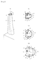
FIG. 1 is a schematic diagram of a self-standing stack to which an exterior wall membrane structure according to the present invention has been applied, where (a) is a general perspective view of the stack, (b) is a plan view of the stack when seen from the top, (c) is a horizontal cross-section of an intermediate portion of the stack, and (d) is a horizontal cross-section of a leg portion of the stack. -
FIG. 2 is a schematic diagram of an integrated stack to which the exterior wall membrane structure according to the present invention has been applied in the same manner asFIG. 1 . -
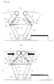
FIG. 3 is a schematic diagram of a first example of a fixing mechanism used for fixing an exterior edge of a membrane member where (a) shows a situation before completion of fixing as seen from above and (b) shows a situation after completion of fixing as seen from above. -
FIG. 4 is a schematic diagram of a second example of a fixing mechanism used for fixing the exterior edge of the membrane member where (a) is a perspective view of a situation after completion of fixing and (b) shows a situation after completion of fixing as seen from above. -
FIG. 5 is a schematic diagram of a third example of a fixing mechanism used for fixing the exterior edge of the membrane member and shows a situation after completion of fixing as seen from above. -
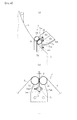
FIG. 6 is an overall perspective view of an exterior wall membrane structure according to the present invention in which a membrane member is fixed to a self-standing stack by using a fourth example of a fixing mechanism. -
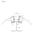
FIG. 7(a) is a schematic diagram of a situation after completion of fixing by using the fourth example of a fixing mechanism as seen from a side, (b) is a cross-section along a line A-A shown in (a), and (c) is an enlarged view of a portion B shown in (b). - The present invention achieves the above object, that is, to present an exterior wall that surrounds the periphery of a stack, that can be designed by giving consideration to the environment, that can be constructed in a short time, and that can have a complex geometric shape that enhances the design, by constructing a membrane member, which is lightweight as compared to concrete, from inside.
- Exemplary embodiments of the present invention are explained below while referring to
FIG. 1 to FIG. 7 . -
FIG. 1 is a schematic diagram of a self-standing stack to which an exterior wall membrane structure according to the present invention has been applied. A self-standing stack is the one that is constructed directly on the ground.FIG. 2 is a schematic diagram of an integrated stack to which the exterior wall membrane structure according to the present invention has been applied. An integrated stack is the one that is coupled to an upper part of a building. - In
FIG. 1 andFIG. 2 ,reference number 1 represents stacks. In this example, twostacks 1 are arranged with a certain distance therebetween. Those twostacks 1 are supported by first steel members 2 (three in the example ofFIG. 1 and four in the example ofFIG. 2 ), andflooring members 3. Thefirst steel members 2 are arranged around thestacks 1. Theflooring members 3 are attached to thefirst steel members 2 at predetermined heights and in an appropriate number. Theflooring members 3 are supported bybeam members 4 that couple and fix thefirst steel members 2. - The periphery of the
stacks 1 is surrounded withmembrane members 5 in order not to impair the scenery. - In the example shown in
FIG. 1 , themembrane members 5 are arranged so as to surround an exterior periphery of the threefirst steel members 2. Theflooring members 3 are hexagonal and attached to thebeam members 4 that couple and fix thefirst steel members 2.Rib members 11 are arranged so as to make a circumscribed circle from the threefirst steel members 2 and theflooring members 3. In a portion where theflooring members 3 are arranged, themembrane members 5 are arranged so as to surround the exterior periphery of therib members 11. - In the example shown in
FIG. 2 , themembrane members 5 are arranged so as to surround an exterior periphery of the fourfirst steel members 2. Theflooring members 3 are quadrangular and attached to thebeam members 4 that couple and fix thefirst steel members 2. Therib members 11 are arranged so as to make an internal portion of the building (excluding the left side inFIG. 2(b) to (d) ) a curved surface from the fourfirst steel members 2 and theflooring members 3. In a portion where theflooring members 3 are arranged, themembrane members 5 are arranged so as to surround the exterior periphery of therib members 11. In the example shown inFIG. 2 , theflooring members 3 arranged in an upper portion of the structure are trapezoidal, and those arranged in a middle portion and a leg portion are rectangular.Second steel members 6 are arranged so as to protrude out from a central portion of twoopposing beam members 4, and themembrane members 5 are arranged so as to surround the tip portions of thesecond steel members 6. - In the example shown in
FIG. 1 , exterior edges of theadjacent membrane members 5, which surround the exterior periphery of thestacks 1 in this manner, are, for example, at the positions of the threefirst steel members 2, drawn toward the inner side of the structure and fixed to each other. Thus, in the example shown inFIG. 1 , threemembrane members 5 are arranged in the circumferential direction of the structure. - On the other hand, in the example shown in
FIG. 2 , exterior edges ofadjacent membrane members 5 are, at the positions of thesecond steel members 6, which protrude out from a central portion of twoopposing beam members 4, drawn toward inner side of the structure and fixed to each other. Thus, in the example shown inFIG. 2 , twomembrane members 5 are arranged in the circumferential direction of the structure. - A fixing mechanism that fixes the exterior edges of the
adjacent membrane members 5 that are drawn toward the inner side of the structure at the positions of thefirst steel members 2 or thesecond steel members 6 includes a drawing member and a fixing tool. The drawing member is arranged at a position at which the exterior edges of theadjacent membrane members 5 are drawn toward the inner side, and the fixing tool fixes the exterior edges that are drawn in the drawing member. Examples of the fixing mechanism are shown inFIG. 3 to FIG. 5 . - A
fixing mechanism 7 shown inFIG. 3 includes a pair of crooked opposingnipping levers 7a. Each of the nippinglevers 7a has a base end and a tip end. The tip ends of the nipping levers 7a approach or separate from each other when the nipping levers 7a swing with the base end as a pivot 7aa. Alocking tool 7b that locks the exterior edge of themembrane member 5 is attached to each of the nipping levers 7a at a position that is toward the tip end relative to a central bent portion 7ab. Moreover, a swinging and fixingmechanism 7c capable of swinging the tip ends of the nippinglevers 7a causing the tip ends to approach or separate from each other is arranged at a position that is toward the base end relative to the central bent portion 7ab of the nippinglevers 7a. In the example shown inFIG. 3 , the swinging and fixingmechanism 7c includes a screw shaft 7ca arranged across both the nipping levers 7a, and a nut 7cb that is screwed into the screw shaft 7ca, and the swinging and fixing of the nippinglevers 7a is realized by loosening or tightening the nut 7cb. - The
locking tool 7b has a hole 7ba and a slit 7bb from which the hole 7ba communicates to the outside. The exterior edge of themembrane member 5 is rolled and made into a closed loop and an edge rope is integrally inserted into the loop of the exterior edge. This exterior edge with the edge rope is then inserted into the hole 7ba via the slit 7bb from vertical cross-sectional direction. In the example shown inFIG. 3 , thelocking tool 7b is fixed to therespective nipping lever 7a with atension rod 12. - In the
fixing mechanism 7 shown inFIG. 3 , awater sealing rubber 8 can be inserted between the tip ends of the nipping levers 7a when drawing the exterior edges of themembrane members 5 and fixing the exterior edges. Thewater sealing rubber 8 prevents entry of water inside the structure while the exterior edges of themembrane members 5 are being drawn and fixed. In the example shown inFIG. 3 , aninner membrane member 9 is arranged between opposinglocking tools 7b to surely prevent the entry of water inside the structure after the exterior edges of themembrane members 5 are drawn and fixed. - In the embodiment shown in
FIG. 3 , the nipping levers 7a and the swinging and fixingmechanism 7c together constitute the drawing member, and thelocking tools 7b constitutes the fixing tool. - The
fixing mechanism 7 shown inFIG. 4 includes a pair ofpipe members 7d arranged side by side with a gap d1 that allows insertion of the exterior edges of themembrane members 5. The exterior edges of themembrane members 5 that are inserted from the gap d1 between thepipe members 7d are then integrally fixed by using atightening tool 7e. In the example shown inFIG. 4 , thetightening tool 7e includes a pair of membrane fixing plates 7ea that sandwich the exterior edges of themembrane members 5, and a fixing bolt 7eb and a nut 7ec that keep the membrane fixing plates 7ea together. In thistightening tool 7e, the exterior edges of themembrane members 5 are integrally fixed to each other by tightening the nut 7ec. - It should be noted that, the exterior edges of the
membrane members 5 can be integrally fixed to each other by using thelocking tool 7b and thetension rod 12 instead of using thetightening tool 7e. - In the
fixing mechanism 7 shown inFIG. 4 , thewater sealing rubber 8 can be inserted in the gap d1 between thepipe members 7d from which the exterior edges of themembrane members 5 that are inserted when drawing the exterior edges of themembrane members 5 and fixing the exterior edges. Thewater sealing rubber 8 prevents entry of water inside the structure while the exterior edges of themembrane members 5 are being drawn and fixed. InFIG. 4 , areference number 10 represents the edge ropes that are integrated with the exterior edges of themembrane members 5. The exterior edge of themembrane member 5 is rolled and made into a closed loop by thermal welding and the like, and then anedge rope 10 is integrally inserted into the loop of the exterior edge. - In the embodiment shown in
FIG. 4 , thepipe members 7d constitute the drawing member, and thetightening tool 7e constitutes the fixing tool. - The
fixing mechanism 7 shown inFIG. 5 includes a pair ofpipe members 7f arranged with an interval d2 and attached to a tip portion of thefirst steel member 2 or thesecond steel member 6,tension rods 7g with base ends thereof attached to thefirst steel member 2 or thesecond steel member 6, andlocking tools 7h attached to tip ends of thetension rods 7g. The exterior edges of themembrane members 5 are drawn by turning around the peripheral surfaces of thepipe members 7f and then fixed with thelocking tools 7h. - In the
fixing mechanism 7 shown inFIG. 5 , a waterentry prevention membrane 7i that encloses the tip end of thefirst steel member 2 or thesecond steel member 6 can be arranged to prevent entry of water inside the structure while the exterior edges of themembrane members 5 are being drawn and fixed. One end of the waterentry prevention membrane 7i is attached to thefirst steel member 2 or thesecond steel member 6, and the other end thereof is welded to themembrane member 5 by thermal welding and the like. - In the embodiment shown in
FIG. 5 , the pair ofpipe members 7f attached in a protruding manner to the tip portion of thefirst steel member 2 or thesecond steel member 6, and the pair oftension rods 7g attached to thefirst steel member 2 or thesecond steel member 6 constitute the drawing member, and thelocking tool 7h constitutes the fixing tool. - In the example shown in
FIG. 1 , the exterior wall membrane structure according to the present invention includes surrounding the exterior peripheral portions of thefirst steel members 2 that support thestacks 1 with themembrane members 5 to form a structure that has thefirst steel members 2 at apices thereof. In the example shown inFIG. 2 , the exterior wall membrane structure according to the present invention includes surrounding the exterior peripheral portions of thefirst steel members 2 to support thestacks 1 and thesecond steel members 6 with themembrane members 5 to form a structure that has thefirst steel members 2 and thesecond steel members 6 at apices thereof. This work can be carried out from inside eliminating the need to construct a dedicated scaffold on the outside of thefirst steel members 2 and thesecond steel members 6. - Moreover, in the example shown in
FIG. 1 , the exterior edges of theadjacent membrane members 5 are drawn from the outside to the inside of the structure at the positions of the threefirst steel members 2, and at the drawn location, those drawn exterior edges are fixed by using thefixing mechanism 7 shown in any one ofFIG. 3 to FIG. 5 . In the example shown inFIG. 2 , the exterior edges of theadjacent membrane members 5 are drawn from the outside to the inside of the structure at the positions of the twosteel members 6, and at the drawn location, those drawn exterior edges are fixed by using thefixing mechanism 7 shown in any one ofFIG. 3 to FIG. 5 . This constitutes the exterior wall membrane construction method according to the present invention. - According to the present invention having the above-explained structure, because the
membrane member 5 that is lightweight as compared to concrete has been used, the foundation work can be reduced. Moreover, because thefirst steel members 2 that support thestacks 1 also serve as the support members that support themembrane members 5, the construction period can be drastically shortened, and the construction cost can also be drastically reduced. - Moreover, because the construction work can be carried out from inside of the exterior wall membrane structure, the scaffold becomes unnecessary, and therefore, the construction period can be further shortened, and the construction cost can be further reduced.
- Moreover, by providing more steel members in addition to the
first steel members 2 that support thestacks 1, not limited to the shapes shown inFIG. 1 andFIG. 2 , shapes having depressions can be dealt with making it possible to construct an exterior wall having a complex geometric shape that enhances the design. - Moreover, according to the present invention, when there is time-related deterioration of the exterior wall of the
stacks 1, the industrial design applied to the exterior wall can be easily changed when repairing the exterior wall, and, this repair can be made in a short time. - Moreover, as long as the
membrane member 5 used in the present invention possesses durability and thermal resistance necessary for the exterior wall of thestacks 1, the material of themembrane member 5 does not matter. For example, glass fiber having a coating of fluororesin can be used for themembrane member 5. - In addition, if the exteriormost layer of the
membrane member 5 is subjected to an anti-smudge treatment, such as coating a photocatalyst layer, then smudge due to time-related change reduces, and maintainability can be improved. Furthermore, if themembrane member 5 that allows passage of light is used, a fantastic environment can be produced in the night time by installing decorative lights on the inner side of themembrane member 5. - The present invention is by no means limited to the above-explained examples. It is needless to say that the embodiments of the present invention can be appropriately modified as long as the technical idea falls within the scope of the claims.
- For example, the examples shown in
FIG. 1 andFIG. 2 assume that a single piece of themembrane member 5 is used in the height direction; however, plural pieces of themembrane member 5 can be used in the height direction. Moreover, themembrane member 5 can be wound obliquely. - Moreover, the exterior wall membrane structure shown in
FIG. 1 andFIG. 2 that uses thefixing mechanism 7 shown inFIG. 3 to FIG. 5 has substantially similar structure in the horizontal cross-section taken at any location from the base end to the tip end of the stack. However, as shown inFIG. 6 , it is possible to construct an exterior wall membrane structure having an enhanced design in which the horizontal cross-sections taken at different locations from the base end to the tip end of the stack have different structures. - When the horizontal cross-sections taken at different locations from the base end to the tip end of the stack have different structures, as in the case of the exterior wall membrane structure shown in
FIG. 6 , thefixing mechanism 7 shown inFIG. 7 , for example, can be used. - The
fixing mechanism 7 shown inFIG. 7 includes alocking tool 7j, aU-shaped plate member 7k, and abolt 7n and a nut 7o that fix theU-shaped plate member 7k to thelocking tool 7j. Thelocking tool 7j includes a hole 7ja and a slit 7jb from which the hole 7ja communicates to the outside. An exterior edge of themembrane member 5 is rolled and made into a closed loop and theedge rope 10 is integrally inserted into this loop. This exterior edge of themembrane member 5 with theedge rope 10 is inserted into the hole 7ja via the slit 7jb from a vertical cross-sectional direction. -
Plural wires 7m are appropriately stretched around the stacks from the base end to the tip end thereof to form a predetermined horizontal cross-sectional shape, and the curved end of theU-shaped plate member 7k is engaged with one of thewires 7m. Thewires 7m can be stretched from, for example, a support member located at an upper part of the stacks (thefirst steel members 2, thebeam members 4, or the second steel members 6) to a support member located at a lower part of the stacks (a foundation of the stacks in case of the self-standing stack shown inFIG. 1 , or a support member arranged at an upper part of the building in case of the integrated stack shown inFIG. 2 ) . - When the
fixing mechanism 7 shown inFIG. 7 is used, the exterior edges of themembrane members 5 can be fixed by simply stretching thewires 7m at predetermined positions without passing them through steel members. As shown inFIG. 7 , the exterior edges of the adjacent membrane members 5 (or separate membrane members attached to those exterior edges by welding) can be attached to asquare member 7q that is attached to one of thelocking tools 7j via anangle member 7p. This structure insulates the fixing parts from outside and prevents entry of water inside the structure. Moreover, thefixing mechanism 7 shown inFIG. 7 allows fixing of themembrane member 5 at an appropriate position other than the exterior edge of themembrane member 5. -
- 1
- stack
- 2
- first steel member
- 3
- flooring member
- 5
- membrane member
- 6
- second steel member
- 7
- fixing mechanism
- 7a
- nipping lever
- 7aa
- pivot
- 7b
- locking tool
- 7c
- swinging and fixing mechanism
- 7d
- pipe member
- 7e
- tightening tool
- 7f
- pipe member
- 7g
- tension rod
- 7h,
- 7j locking tool
- 7k
- plate member
- 7m
- wire
Claims (7)
- A method of constructing an exterior wall membrane around a stack, comprising:surrounding with a membrane member an exterior side of first steel members that are arranged around the stack to support the stack, or second steel members that are arranged on the first steel members, and then fixing a membrane member exterior edge that is an exterior edge of the membrane member and, if required, an appropriate position of the membrane member other than the membrane member exterior edge.
- An exterior wall membrane structure capable of being arranged around a stack, comprising:surrounding with a membrane member an exterior side of first steel members that are arranged around the stack to support the stack, or second steel members that are arranged on the first steel members, and fixing a membrane member exterior edge that is an exterior edge of the membrane member and, if required, an appropriate position of the membrane member other than the membrane member exterior edge.
- The exterior wall membrane structure of a stack according to Claim 2, wherein a fixing mechanism that fixes the exterior edge includes
a drawing member that is arranged at a position of the shape at which the exterior edge is drawn from outside to inside; and
a fixing tool that fixes the exterior edge drawn in the drawing member. - The exterior wall membrane structure of a stack according to Claim 3, wherein the fixing tool includes
a pair of nipping levers having a base end and a tip end, the tip ends of the nipping levers approach or separate from each other by swinging with the base end as a pivot;
a locking tool that is attached to each of the nipping levers and that locks the exterior edge of the membrane member; and
a swinging and fixing mechanism capable of swinging and fixing the nipping levers. - The exterior wall membrane structure of a stack according to Claim 3, wherein the fixing tool includes
a pair of pipe members arranged side by side with a gap that allows insertion of the membrane members; and
a tightening tool that integrally fixes the exterior edges of the membrane members that are inserted from the gap between the pipe members. - The exterior wall membrane structure of a stack according to Claim 3, wherein the fixing tool includes
a pair of pipe members attached in a protruding manner to a tip portion of the first steel members or the second steel members with a predetermined interval;
locking tools that lock the exterior edges of the membrane members that are drawn by turning around the peripheral surfaces of the pipe members; and
tension rods that fix the fixing tools to the membrane fixing member. - The exterior wall membrane structure of a stack according to Claim 2, wherein the fixing mechanism that fixes the exterior edge of the membrane member includes
a locking tool that locks a locking member arranged at a necessary position of the membrane member; and
a plate member attached to the locking tool,
wherein the membrane member locked with the locking tool is fixed by engaging the plate member to a wire arranged on an exterior side of the stack.
Applications Claiming Priority (1)
| Application Number | Priority Date | Filing Date | Title |
|---|---|---|---|
| PCT/JP2012/076239 WO2014057545A1 (en) | 2012-10-10 | 2012-10-10 | Outer wall membrane construction method and outer wall membrane structure for chimney stacks |
Publications (3)
| Publication Number | Publication Date |
|---|---|
| EP2918752A1 true EP2918752A1 (en) | 2015-09-16 |
| EP2918752A4 EP2918752A4 (en) | 2016-08-24 |
| EP2918752B1 EP2918752B1 (en) | 2019-07-17 |
Family
ID=50477034
Family Applications (1)
| Application Number | Title | Priority Date | Filing Date |
|---|---|---|---|
| EP12886498.0A Active EP2918752B1 (en) | 2012-10-10 | 2012-10-10 | Outer wall membrane construction method and outer wall membrane structure for chimney stacks |
Country Status (5)
| Country | Link |
|---|---|
| EP (1) | EP2918752B1 (en) |
| KR (1) | KR20150068408A (en) |
| CN (1) | CN104662240B (en) |
| SG (1) | SG11201502173TA (en) |
| WO (1) | WO2014057545A1 (en) |
Family Cites Families (16)
| Publication number | Priority date | Publication date | Assignee | Title |
|---|---|---|---|---|
| DD128358A1 (en) * | 1977-02-17 | 1977-11-16 | Hoetechnika Epitoe Es Szigetel | A SMOKE TUBE ARRANGED IN THE LOAD-BEARING CONSTRUCTION THROUGH CEILING INTO SEVERAL LEVELS |
| DE2845194A1 (en) * | 1978-10-17 | 1980-04-30 | Leonhardt Fritz | SADDLE-SHAPED SHEATH FOR TUBULAR CONSTRUCTIONS AND METHOD FOR THE PRODUCTION THEREOF |
| US4593510A (en) * | 1984-10-31 | 1986-06-10 | Newsome R Wayne | Pre-fabricated and modular chimney facade system |
| US5033240A (en) * | 1990-06-01 | 1991-07-23 | Richard Louis J | Method and apparatus to enshroud large vertical structures |
| JPH0490434A (en) * | 1990-08-02 | 1992-03-24 | Mitsui Eng & Shipbuild Co Ltd | Method for ventilating incineration equipment |
| KR970005008B1 (en) * | 1991-01-10 | 1997-04-11 | 가부시끼가이샤 에스씨이에스 기카쿠 | Sheet stretcher including sheet attachment holes and sheet connection means |
| JPH0666051A (en) | 1992-08-20 | 1994-03-08 | Tokyo Electric Power Co Inc:The | Chimney |
| CN1087155A (en) * | 1993-11-19 | 1994-05-25 | 骆锡耀 | Fan-shaped cellular-type steel stack such as full circle and air-rise upside-down job practices thereof |
| JP3174677B2 (en) * | 1993-11-30 | 2001-06-11 | 三菱重工業株式会社 | Tower-like structure erection equipment |
| JP2808079B2 (en) * | 1994-06-24 | 1998-10-08 | 太陽工業株式会社 | Membrane tension introduction structure |
| DE4430876C1 (en) * | 1994-08-31 | 1995-07-13 | Philips Patentverwaltung | Communication system including exchange accepting external service, e.g. credit card calling |
| US6021702A (en) * | 1998-02-09 | 2000-02-08 | Rexroad; John | Aesthetic barrier/debris system and material |
| JP2002047831A (en) * | 2000-08-04 | 2002-02-15 | Taiyo Kogyo Corp | Structural member used also as membrane backing for membrane structure building |
| JP3906902B2 (en) * | 2001-09-28 | 2007-04-18 | 太陽工業株式会社 | Fixing structure for intermediate part of film material |
| JP2005256999A (en) * | 2004-03-12 | 2005-09-22 | Takenaka Komuten Co Ltd | Membrane structure fixing structure |
| CN103883152B (en) * | 2012-12-21 | 2016-05-25 | 河南省电力勘测设计院 | A kind of novel rope net membrane structure inner core cigarette tower combined structure system |
-
2012
- 2012-10-10 SG SG11201502173TA patent/SG11201502173TA/en unknown
- 2012-10-10 EP EP12886498.0A patent/EP2918752B1/en active Active
- 2012-10-10 KR KR1020157010681A patent/KR20150068408A/en not_active Ceased
- 2012-10-10 CN CN201280076025.9A patent/CN104662240B/en active Active
- 2012-10-10 WO PCT/JP2012/076239 patent/WO2014057545A1/en not_active Ceased
Also Published As
| Publication number | Publication date |
|---|---|
| SG11201502173TA (en) | 2015-05-28 |
| WO2014057545A1 (en) | 2014-04-17 |
| EP2918752A4 (en) | 2016-08-24 |
| CN104662240B (en) | 2016-10-12 |
| KR20150068408A (en) | 2015-06-19 |
| CN104662240A (en) | 2015-05-27 |
| EP2918752B1 (en) | 2019-07-17 |
Similar Documents
| Publication | Publication Date | Title |
|---|---|---|
| ES2321958T3 (en) | MODULAR TRANSPORT BUILDING AND METHOD TO MANUFACTURE IT. | |
| US10982406B2 (en) | Tower foundation with concrete box girder beams | |
| ES2343450T1 (en) | IMPROVED MODULAR TOWER STRUCTURE FOR WIND TURBINES AND OTHER APPLICATIONS. | |
| ES2968667T3 (en) | Hybrid tube for tie rod and its manufacturing procedure | |
| ITMI20091559A1 (en) | IMPROVED FOUNDATION FOR WIND TOWER | |
| WO2014050901A1 (en) | Column base hardware and column base structure using same | |
| JP2012067582A (en) | Reinforcement structure for water storage tank | |
| KR20200090388A (en) | Assembling type viewing tower | |
| KR102167960B1 (en) | Steel Pipe Girder for Bridge with Improved Reinforcement Structure | |
| AU2015299764B2 (en) | Coupling an upper end of a hollow section column to a building unit support | |
| CN107849864B (en) | Tower of a wind power plant | |
| JP2005350904A (en) | Cofferdam structure and cofferdam construction method | |
| JP2009030345A (en) | Assembly type solid structure | |
| EP2918752B1 (en) | Outer wall membrane construction method and outer wall membrane structure for chimney stacks | |
| JP4104158B2 (en) | Installation method of opening reinforcement in reinforced concrete building | |
| ES2367069T3 (en) | PANEL ELEMENT WITH REINFORCEMENT. | |
| KR101288744B1 (en) | Scaffoldings for the Scrubber | |
| JP5702213B2 (en) | Chimney outer wall membrane construction method and outer wall membrane structure | |
| JP2003268937A (en) | Roof support hardware mounting structure | |
| JP4361557B2 (en) | Assembled frame structure | |
| JP3480915B2 (en) | tank | |
| JP5769996B2 (en) | Foundation structure | |
| WO2018146202A1 (en) | A resuable modular building and a method for erecting the same | |
| CN116685749A (en) | installation profile | |
| JP6535265B2 (en) | Mounting bracket and mounting method |
Legal Events
| Date | Code | Title | Description |
|---|---|---|---|
| PUAI | Public reference made under article 153(3) epc to a published international application that has entered the european phase |
Free format text: ORIGINAL CODE: 0009012 |
|
| 17P | Request for examination filed |
Effective date: 20150416 |
|
| AK | Designated contracting states |
Kind code of ref document: A1 Designated state(s): AL AT BE BG CH CY CZ DE DK EE ES FI FR GB GR HR HU IE IS IT LI LT LU LV MC MK MT NL NO PL PT RO RS SE SI SK SM TR |
|
| AX | Request for extension of the european patent |
Extension state: BA ME |
|
| DAX | Request for extension of the european patent (deleted) | ||
| RA4 | Supplementary search report drawn up and despatched (corrected) |
Effective date: 20160725 |
|
| RIC1 | Information provided on ipc code assigned before grant |
Ipc: E04H 12/28 20060101AFI20160719BHEP Ipc: E04F 17/02 20060101ALI20160719BHEP |
|
| STAA | Information on the status of an ep patent application or granted ep patent |
Free format text: STATUS: EXAMINATION IS IN PROGRESS |
|
| 17Q | First examination report despatched |
Effective date: 20171117 |
|
| REG | Reference to a national code |
Ref country code: DE Ref legal event code: R079 Ref document number: 602012062175 Country of ref document: DE Free format text: PREVIOUS MAIN CLASS: E04H0012280000 Ipc: E04H0015640000 |
|
| GRAP | Despatch of communication of intention to grant a patent |
Free format text: ORIGINAL CODE: EPIDOSNIGR1 |
|
| STAA | Information on the status of an ep patent application or granted ep patent |
Free format text: STATUS: GRANT OF PATENT IS INTENDED |
|
| RIC1 | Information provided on ipc code assigned before grant |
Ipc: E04H 15/64 20060101AFI20190218BHEP |
|
| INTG | Intention to grant announced |
Effective date: 20190312 |
|
| GRAS | Grant fee paid |
Free format text: ORIGINAL CODE: EPIDOSNIGR3 |
|
| GRAA | (expected) grant |
Free format text: ORIGINAL CODE: 0009210 |
|
| STAA | Information on the status of an ep patent application or granted ep patent |
Free format text: STATUS: THE PATENT HAS BEEN GRANTED |
|
| AK | Designated contracting states |
Kind code of ref document: B1 Designated state(s): AL AT BE BG CH CY CZ DE DK EE ES FI FR GB GR HR HU IE IS IT LI LT LU LV MC MK MT NL NO PL PT RO RS SE SI SK SM TR |
|
| REG | Reference to a national code |
Ref country code: GB Ref legal event code: FG4D |
|
| REG | Reference to a national code |
Ref country code: CH Ref legal event code: EP |
|
| REG | Reference to a national code |
Ref country code: IE Ref legal event code: FG4D |
|
| REG | Reference to a national code |
Ref country code: DE Ref legal event code: R096 Ref document number: 602012062175 Country of ref document: DE |
|
| REG | Reference to a national code |
Ref country code: AT Ref legal event code: REF Ref document number: 1155969 Country of ref document: AT Kind code of ref document: T Effective date: 20190815 |
|
| REG | Reference to a national code |
Ref country code: NL Ref legal event code: MP Effective date: 20190717 |
|
| REG | Reference to a national code |
Ref country code: LT Ref legal event code: MG4D |
|
| REG | Reference to a national code |
Ref country code: AT Ref legal event code: MK05 Ref document number: 1155969 Country of ref document: AT Kind code of ref document: T Effective date: 20190717 |
|
| PG25 | Lapsed in a contracting state [announced via postgrant information from national office to epo] |
Ref country code: FI Free format text: LAPSE BECAUSE OF FAILURE TO SUBMIT A TRANSLATION OF THE DESCRIPTION OR TO PAY THE FEE WITHIN THE PRESCRIBED TIME-LIMIT Effective date: 20190717 Ref country code: LT Free format text: LAPSE BECAUSE OF FAILURE TO SUBMIT A TRANSLATION OF THE DESCRIPTION OR TO PAY THE FEE WITHIN THE PRESCRIBED TIME-LIMIT Effective date: 20190717 Ref country code: HR Free format text: LAPSE BECAUSE OF FAILURE TO SUBMIT A TRANSLATION OF THE DESCRIPTION OR TO PAY THE FEE WITHIN THE PRESCRIBED TIME-LIMIT Effective date: 20190717 Ref country code: NO Free format text: LAPSE BECAUSE OF FAILURE TO SUBMIT A TRANSLATION OF THE DESCRIPTION OR TO PAY THE FEE WITHIN THE PRESCRIBED TIME-LIMIT Effective date: 20191017 Ref country code: BG Free format text: LAPSE BECAUSE OF FAILURE TO SUBMIT A TRANSLATION OF THE DESCRIPTION OR TO PAY THE FEE WITHIN THE PRESCRIBED TIME-LIMIT Effective date: 20191017 Ref country code: SE Free format text: LAPSE BECAUSE OF FAILURE TO SUBMIT A TRANSLATION OF THE DESCRIPTION OR TO PAY THE FEE WITHIN THE PRESCRIBED TIME-LIMIT Effective date: 20190717 Ref country code: NL Free format text: LAPSE BECAUSE OF FAILURE TO SUBMIT A TRANSLATION OF THE DESCRIPTION OR TO PAY THE FEE WITHIN THE PRESCRIBED TIME-LIMIT Effective date: 20190717 Ref country code: PT Free format text: LAPSE BECAUSE OF FAILURE TO SUBMIT A TRANSLATION OF THE DESCRIPTION OR TO PAY THE FEE WITHIN THE PRESCRIBED TIME-LIMIT Effective date: 20191118 Ref country code: AT Free format text: LAPSE BECAUSE OF FAILURE TO SUBMIT A TRANSLATION OF THE DESCRIPTION OR TO PAY THE FEE WITHIN THE PRESCRIBED TIME-LIMIT Effective date: 20190717 |
|
| PG25 | Lapsed in a contracting state [announced via postgrant information from national office to epo] |
Ref country code: ES Free format text: LAPSE BECAUSE OF FAILURE TO SUBMIT A TRANSLATION OF THE DESCRIPTION OR TO PAY THE FEE WITHIN THE PRESCRIBED TIME-LIMIT Effective date: 20190717 Ref country code: AL Free format text: LAPSE BECAUSE OF FAILURE TO SUBMIT A TRANSLATION OF THE DESCRIPTION OR TO PAY THE FEE WITHIN THE PRESCRIBED TIME-LIMIT Effective date: 20190717 Ref country code: LV Free format text: LAPSE BECAUSE OF FAILURE TO SUBMIT A TRANSLATION OF THE DESCRIPTION OR TO PAY THE FEE WITHIN THE PRESCRIBED TIME-LIMIT Effective date: 20190717 Ref country code: IS Free format text: LAPSE BECAUSE OF FAILURE TO SUBMIT A TRANSLATION OF THE DESCRIPTION OR TO PAY THE FEE WITHIN THE PRESCRIBED TIME-LIMIT Effective date: 20191117 Ref country code: RS Free format text: LAPSE BECAUSE OF FAILURE TO SUBMIT A TRANSLATION OF THE DESCRIPTION OR TO PAY THE FEE WITHIN THE PRESCRIBED TIME-LIMIT Effective date: 20190717 Ref country code: GR Free format text: LAPSE BECAUSE OF FAILURE TO SUBMIT A TRANSLATION OF THE DESCRIPTION OR TO PAY THE FEE WITHIN THE PRESCRIBED TIME-LIMIT Effective date: 20191018 |
|
| PG25 | Lapsed in a contracting state [announced via postgrant information from national office to epo] |
Ref country code: TR Free format text: LAPSE BECAUSE OF FAILURE TO SUBMIT A TRANSLATION OF THE DESCRIPTION OR TO PAY THE FEE WITHIN THE PRESCRIBED TIME-LIMIT Effective date: 20190717 |
|
| PG25 | Lapsed in a contracting state [announced via postgrant information from national office to epo] |
Ref country code: PL Free format text: LAPSE BECAUSE OF FAILURE TO SUBMIT A TRANSLATION OF THE DESCRIPTION OR TO PAY THE FEE WITHIN THE PRESCRIBED TIME-LIMIT Effective date: 20190717 Ref country code: EE Free format text: LAPSE BECAUSE OF FAILURE TO SUBMIT A TRANSLATION OF THE DESCRIPTION OR TO PAY THE FEE WITHIN THE PRESCRIBED TIME-LIMIT Effective date: 20190717 Ref country code: RO Free format text: LAPSE BECAUSE OF FAILURE TO SUBMIT A TRANSLATION OF THE DESCRIPTION OR TO PAY THE FEE WITHIN THE PRESCRIBED TIME-LIMIT Effective date: 20190717 Ref country code: IT Free format text: LAPSE BECAUSE OF FAILURE TO SUBMIT A TRANSLATION OF THE DESCRIPTION OR TO PAY THE FEE WITHIN THE PRESCRIBED TIME-LIMIT Effective date: 20190717 Ref country code: DK Free format text: LAPSE BECAUSE OF FAILURE TO SUBMIT A TRANSLATION OF THE DESCRIPTION OR TO PAY THE FEE WITHIN THE PRESCRIBED TIME-LIMIT Effective date: 20190717 |
|
| PG25 | Lapsed in a contracting state [announced via postgrant information from national office to epo] |
Ref country code: SK Free format text: LAPSE BECAUSE OF FAILURE TO SUBMIT A TRANSLATION OF THE DESCRIPTION OR TO PAY THE FEE WITHIN THE PRESCRIBED TIME-LIMIT Effective date: 20190717 Ref country code: IS Free format text: LAPSE BECAUSE OF FAILURE TO SUBMIT A TRANSLATION OF THE DESCRIPTION OR TO PAY THE FEE WITHIN THE PRESCRIBED TIME-LIMIT Effective date: 20200224 Ref country code: SM Free format text: LAPSE BECAUSE OF FAILURE TO SUBMIT A TRANSLATION OF THE DESCRIPTION OR TO PAY THE FEE WITHIN THE PRESCRIBED TIME-LIMIT Effective date: 20190717 Ref country code: MC Free format text: LAPSE BECAUSE OF FAILURE TO SUBMIT A TRANSLATION OF THE DESCRIPTION OR TO PAY THE FEE WITHIN THE PRESCRIBED TIME-LIMIT Effective date: 20190717 Ref country code: CZ Free format text: LAPSE BECAUSE OF FAILURE TO SUBMIT A TRANSLATION OF THE DESCRIPTION OR TO PAY THE FEE WITHIN THE PRESCRIBED TIME-LIMIT Effective date: 20190717 |
|
| REG | Reference to a national code |
Ref country code: CH Ref legal event code: PL |
|
| REG | Reference to a national code |
Ref country code: DE Ref legal event code: R097 Ref document number: 602012062175 Country of ref document: DE |
|
| PLBE | No opposition filed within time limit |
Free format text: ORIGINAL CODE: 0009261 |
|
| STAA | Information on the status of an ep patent application or granted ep patent |
Free format text: STATUS: NO OPPOSITION FILED WITHIN TIME LIMIT |
|
| PG2D | Information on lapse in contracting state deleted |
Ref country code: IS |
|
| PG25 | Lapsed in a contracting state [announced via postgrant information from national office to epo] |
Ref country code: LU Free format text: LAPSE BECAUSE OF NON-PAYMENT OF DUE FEES Effective date: 20191010 Ref country code: CH Free format text: LAPSE BECAUSE OF NON-PAYMENT OF DUE FEES Effective date: 20191031 Ref country code: LI Free format text: LAPSE BECAUSE OF NON-PAYMENT OF DUE FEES Effective date: 20191031 |
|
| 26N | No opposition filed |
Effective date: 20200603 |
|
| REG | Reference to a national code |
Ref country code: BE Ref legal event code: MM Effective date: 20191031 |
|
| PG25 | Lapsed in a contracting state [announced via postgrant information from national office to epo] |
Ref country code: SI Free format text: LAPSE BECAUSE OF FAILURE TO SUBMIT A TRANSLATION OF THE DESCRIPTION OR TO PAY THE FEE WITHIN THE PRESCRIBED TIME-LIMIT Effective date: 20190717 Ref country code: BE Free format text: LAPSE BECAUSE OF NON-PAYMENT OF DUE FEES Effective date: 20191031 |
|
| GBPC | Gb: european patent ceased through non-payment of renewal fee |
Effective date: 20191017 |
|
| PG25 | Lapsed in a contracting state [announced via postgrant information from national office to epo] |
Ref country code: IE Free format text: LAPSE BECAUSE OF NON-PAYMENT OF DUE FEES Effective date: 20191010 Ref country code: GB Free format text: LAPSE BECAUSE OF NON-PAYMENT OF DUE FEES Effective date: 20191017 |
|
| PG25 | Lapsed in a contracting state [announced via postgrant information from national office to epo] |
Ref country code: CY Free format text: LAPSE BECAUSE OF FAILURE TO SUBMIT A TRANSLATION OF THE DESCRIPTION OR TO PAY THE FEE WITHIN THE PRESCRIBED TIME-LIMIT Effective date: 20190717 |
|
| PG25 | Lapsed in a contracting state [announced via postgrant information from national office to epo] |
Ref country code: HU Free format text: LAPSE BECAUSE OF FAILURE TO SUBMIT A TRANSLATION OF THE DESCRIPTION OR TO PAY THE FEE WITHIN THE PRESCRIBED TIME-LIMIT; INVALID AB INITIO Effective date: 20121010 Ref country code: MT Free format text: LAPSE BECAUSE OF FAILURE TO SUBMIT A TRANSLATION OF THE DESCRIPTION OR TO PAY THE FEE WITHIN THE PRESCRIBED TIME-LIMIT Effective date: 20190717 |
|
| PG25 | Lapsed in a contracting state [announced via postgrant information from national office to epo] |
Ref country code: MK Free format text: LAPSE BECAUSE OF FAILURE TO SUBMIT A TRANSLATION OF THE DESCRIPTION OR TO PAY THE FEE WITHIN THE PRESCRIBED TIME-LIMIT Effective date: 20190717 |
|
| P01 | Opt-out of the competence of the unified patent court (upc) registered |
Effective date: 20230510 |
|
| PGFP | Annual fee paid to national office [announced via postgrant information from national office to epo] |
Ref country code: FR Payment date: 20250908 Year of fee payment: 14 |
|
| PGFP | Annual fee paid to national office [announced via postgrant information from national office to epo] |
Ref country code: DE Payment date: 20250902 Year of fee payment: 14 |