EP2918718B1 - Waved meltblown fiber web and preparation method therefor - Google Patents
Waved meltblown fiber web and preparation method therefor Download PDFInfo
- Publication number
- EP2918718B1 EP2918718B1 EP13853540.6A EP13853540A EP2918718B1 EP 2918718 B1 EP2918718 B1 EP 2918718B1 EP 13853540 A EP13853540 A EP 13853540A EP 2918718 B1 EP2918718 B1 EP 2918718B1
- Authority
- EP
- European Patent Office
- Prior art keywords
- fibers
- meltblown
- fiber web
- waved
- microfibers
- Prior art date
- Legal status (The legal status is an assumption and is not a legal conclusion. Google has not performed a legal analysis and makes no representation as to the accuracy of the status listed.)
- Active
Links
- 239000000835 fiber Substances 0.000 title claims description 226
- 238000002360 preparation method Methods 0.000 title 1
- 229920001410 Microfiber Polymers 0.000 claims description 47
- 239000003658 microfiber Substances 0.000 claims description 47
- 238000010521 absorption reaction Methods 0.000 claims description 27
- -1 polypropylene Polymers 0.000 claims description 18
- 239000004743 Polypropylene Substances 0.000 claims description 10
- 239000004744 fabric Substances 0.000 claims description 10
- 238000000034 method Methods 0.000 claims description 10
- 229920001155 polypropylene Polymers 0.000 claims description 10
- 239000004698 Polyethylene Substances 0.000 claims description 7
- 229920000573 polyethylene Polymers 0.000 claims description 7
- 229920000139 polyethylene terephthalate Polymers 0.000 claims description 7
- 239000005020 polyethylene terephthalate Substances 0.000 claims description 7
- 239000004745 nonwoven fabric Substances 0.000 claims description 6
- 239000012774 insulation material Substances 0.000 claims description 4
- 229920001778 nylon Polymers 0.000 claims description 4
- OKTJSMMVPCPJKN-UHFFFAOYSA-N Carbon Chemical compound [C] OKTJSMMVPCPJKN-UHFFFAOYSA-N 0.000 claims description 3
- 229910052799 carbon Inorganic materials 0.000 claims description 3
- 244000025254 Cannabis sativa Species 0.000 claims description 2
- 235000012766 Cannabis sativa ssp. sativa var. sativa Nutrition 0.000 claims description 2
- 235000012765 Cannabis sativa ssp. sativa var. spontanea Nutrition 0.000 claims description 2
- 229920000742 Cotton Polymers 0.000 claims description 2
- 235000009120 camo Nutrition 0.000 claims description 2
- 235000005607 chanvre indien Nutrition 0.000 claims description 2
- 230000009977 dual effect Effects 0.000 claims description 2
- 239000003365 glass fiber Substances 0.000 claims description 2
- 239000011487 hemp Substances 0.000 claims description 2
- 239000012510 hollow fiber Substances 0.000 claims description 2
- 230000001788 irregular Effects 0.000 claims description 2
- 229920005615 natural polymer Polymers 0.000 claims description 2
- 229920001059 synthetic polymer Polymers 0.000 claims description 2
- 230000000052 comparative effect Effects 0.000 description 32
- 238000004519 manufacturing process Methods 0.000 description 19
- 238000000151 deposition Methods 0.000 description 18
- 238000009987 spinning Methods 0.000 description 17
- 230000008859 change Effects 0.000 description 16
- 230000008021 deposition Effects 0.000 description 16
- 238000012360 testing method Methods 0.000 description 14
- 229920005992 thermoplastic resin Polymers 0.000 description 13
- 239000007789 gas Substances 0.000 description 8
- 229910000831 Steel Inorganic materials 0.000 description 7
- 239000011342 resin composition Substances 0.000 description 7
- 239000010959 steel Substances 0.000 description 7
- 238000005259 measurement Methods 0.000 description 4
- 239000000203 mixture Substances 0.000 description 4
- 239000000126 substance Substances 0.000 description 4
- LYCAIKOWRPUZTN-UHFFFAOYSA-N Ethylene glycol Chemical compound OCCO LYCAIKOWRPUZTN-UHFFFAOYSA-N 0.000 description 3
- 230000000694 effects Effects 0.000 description 3
- 239000000155 melt Substances 0.000 description 3
- 229920000728 polyester Polymers 0.000 description 3
- 229920000642 polymer Polymers 0.000 description 3
- 239000002952 polymeric resin Substances 0.000 description 3
- 229920003002 synthetic resin Polymers 0.000 description 3
- SWZOQAGVRGQLDV-UHFFFAOYSA-N 4-[2-(4-hydroxy-2,2,6,6-tetramethylpiperidin-1-yl)ethoxy]-4-oxobutanoic acid Chemical compound CC1(C)CC(O)CC(C)(C)N1CCOC(=O)CCC(O)=O SWZOQAGVRGQLDV-UHFFFAOYSA-N 0.000 description 2
- KKEYFWRCBNTPAC-UHFFFAOYSA-N Terephthalic acid Chemical compound OC(=O)C1=CC=C(C(O)=O)C=C1 KKEYFWRCBNTPAC-UHFFFAOYSA-N 0.000 description 2
- 239000012963 UV stabilizer Substances 0.000 description 2
- BGYHLZZASRKEJE-UHFFFAOYSA-N [3-[3-(3,5-ditert-butyl-4-hydroxyphenyl)propanoyloxy]-2,2-bis[3-(3,5-ditert-butyl-4-hydroxyphenyl)propanoyloxymethyl]propyl] 3-(3,5-ditert-butyl-4-hydroxyphenyl)propanoate Chemical compound CC(C)(C)C1=C(O)C(C(C)(C)C)=CC(CCC(=O)OCC(COC(=O)CCC=2C=C(C(O)=C(C=2)C(C)(C)C)C(C)(C)C)(COC(=O)CCC=2C=C(C(O)=C(C=2)C(C)(C)C)C(C)(C)C)COC(=O)CCC=2C=C(C(O)=C(C=2)C(C)(C)C)C(C)(C)C)=C1 BGYHLZZASRKEJE-UHFFFAOYSA-N 0.000 description 2
- WYTGDNHDOZPMIW-RCBQFDQVSA-N alstonine Natural products C1=CC2=C3C=CC=CC3=NC2=C2N1C[C@H]1[C@H](C)OC=C(C(=O)OC)[C@H]1C2 WYTGDNHDOZPMIW-RCBQFDQVSA-N 0.000 description 2
- 150000001408 amides Chemical class 0.000 description 2
- 239000007859 condensation product Substances 0.000 description 2
- 229920001577 copolymer Polymers 0.000 description 2
- 238000002347 injection Methods 0.000 description 2
- 239000007924 injection Substances 0.000 description 2
- 238000012986 modification Methods 0.000 description 2
- 230000004048 modification Effects 0.000 description 2
- 239000002861 polymer material Substances 0.000 description 2
- 229920000098 polyolefin Polymers 0.000 description 2
- 229920005629 polypropylene homopolymer Polymers 0.000 description 2
- 125000004805 propylene group Chemical group [H]C([H])([H])C([H])([*:1])C([H])([H])[*:2] 0.000 description 2
- 229920006395 saturated elastomer Polymers 0.000 description 2
- 229910001220 stainless steel Inorganic materials 0.000 description 2
- 239000010935 stainless steel Substances 0.000 description 2
- 239000003017 thermal stabilizer Substances 0.000 description 2
- JMMZCWZIJXAGKW-UHFFFAOYSA-N 2-methylpent-2-ene Chemical compound CCC=C(C)C JMMZCWZIJXAGKW-UHFFFAOYSA-N 0.000 description 1
- 241000238876 Acari Species 0.000 description 1
- 239000004677 Nylon Substances 0.000 description 1
- 239000004793 Polystyrene Substances 0.000 description 1
- 239000002253 acid Substances 0.000 description 1
- 150000001298 alcohols Chemical class 0.000 description 1
- 125000001931 aliphatic group Chemical group 0.000 description 1
- 230000000843 anti-fungal effect Effects 0.000 description 1
- 125000003118 aryl group Chemical group 0.000 description 1
- 230000002902 bimodal effect Effects 0.000 description 1
- 230000015572 biosynthetic process Effects 0.000 description 1
- 238000002485 combustion reaction Methods 0.000 description 1
- 238000001816 cooling Methods 0.000 description 1
- 238000002425 crystallisation Methods 0.000 description 1
- 230000008025 crystallization Effects 0.000 description 1
- 238000013461 design Methods 0.000 description 1
- 150000001991 dicarboxylic acids Chemical class 0.000 description 1
- 150000002148 esters Chemical group 0.000 description 1
- 229920001519 homopolymer Polymers 0.000 description 1
- 229930195733 hydrocarbon Natural products 0.000 description 1
- 150000002430 hydrocarbons Chemical class 0.000 description 1
- 125000004435 hydrogen atom Chemical group [H]* 0.000 description 1
- 238000009413 insulation Methods 0.000 description 1
- 239000003550 marker Substances 0.000 description 1
- 239000000463 material Substances 0.000 description 1
- 238000002844 melting Methods 0.000 description 1
- 230000008018 melting Effects 0.000 description 1
- 238000005065 mining Methods 0.000 description 1
- 239000000178 monomer Substances 0.000 description 1
- 230000000737 periodic effect Effects 0.000 description 1
- 230000035699 permeability Effects 0.000 description 1
- 229920000306 polymethylpentene Polymers 0.000 description 1
- 239000011116 polymethylpentene Substances 0.000 description 1
- 229920002223 polystyrene Polymers 0.000 description 1
- 239000004800 polyvinyl chloride Substances 0.000 description 1
- 229920000915 polyvinyl chloride Polymers 0.000 description 1
- 230000008569 process Effects 0.000 description 1
- 239000000047 product Substances 0.000 description 1
- QQONPFPTGQHPMA-UHFFFAOYSA-N propylene Natural products CC=C QQONPFPTGQHPMA-UHFFFAOYSA-N 0.000 description 1
- 230000009467 reduction Effects 0.000 description 1
- 229920005989 resin Polymers 0.000 description 1
- 239000011347 resin Substances 0.000 description 1
- 239000000243 solution Substances 0.000 description 1
- 238000010998 test method Methods 0.000 description 1
- 229920001169 thermoplastic Polymers 0.000 description 1
- 238000004804 winding Methods 0.000 description 1
Images


Classifications
-
- B—PERFORMING OPERATIONS; TRANSPORTING
- B32—LAYERED PRODUCTS
- B32B—LAYERED PRODUCTS, i.e. PRODUCTS BUILT-UP OF STRATA OF FLAT OR NON-FLAT, e.g. CELLULAR OR HONEYCOMB, FORM
- B32B5/00—Layered products characterised by the non- homogeneity or physical structure, i.e. comprising a fibrous, filamentary, particulate or foam layer; Layered products characterised by having a layer differing constitutionally or physically in different parts
- B32B5/22—Layered products characterised by the non- homogeneity or physical structure, i.e. comprising a fibrous, filamentary, particulate or foam layer; Layered products characterised by having a layer differing constitutionally or physically in different parts characterised by the presence of two or more layers which are next to each other and are fibrous, filamentary, formed of particles or foamed
- B32B5/24—Layered products characterised by the non- homogeneity or physical structure, i.e. comprising a fibrous, filamentary, particulate or foam layer; Layered products characterised by having a layer differing constitutionally or physically in different parts characterised by the presence of two or more layers which are next to each other and are fibrous, filamentary, formed of particles or foamed one layer being a fibrous or filamentary layer
- B32B5/26—Layered products characterised by the non- homogeneity or physical structure, i.e. comprising a fibrous, filamentary, particulate or foam layer; Layered products characterised by having a layer differing constitutionally or physically in different parts characterised by the presence of two or more layers which are next to each other and are fibrous, filamentary, formed of particles or foamed one layer being a fibrous or filamentary layer another layer next to it also being fibrous or filamentary
-
- B—PERFORMING OPERATIONS; TRANSPORTING
- B29—WORKING OF PLASTICS; WORKING OF SUBSTANCES IN A PLASTIC STATE IN GENERAL
- B29C—SHAPING OR JOINING OF PLASTICS; SHAPING OF MATERIAL IN A PLASTIC STATE, NOT OTHERWISE PROVIDED FOR; AFTER-TREATMENT OF THE SHAPED PRODUCTS, e.g. REPAIRING
- B29C48/00—Extrusion moulding, i.e. expressing the moulding material through a die or nozzle which imparts the desired form; Apparatus therefor
- B29C48/16—Articles comprising two or more components, e.g. co-extruded layers
- B29C48/18—Articles comprising two or more components, e.g. co-extruded layers the components being layers
- B29C48/21—Articles comprising two or more components, e.g. co-extruded layers the components being layers the layers being joined at their surfaces
-
- B—PERFORMING OPERATIONS; TRANSPORTING
- B32—LAYERED PRODUCTS
- B32B—LAYERED PRODUCTS, i.e. PRODUCTS BUILT-UP OF STRATA OF FLAT OR NON-FLAT, e.g. CELLULAR OR HONEYCOMB, FORM
- B32B3/00—Layered products comprising a layer with external or internal discontinuities or unevennesses, or a layer of non-planar shape; Layered products comprising a layer having particular features of form
- B32B3/26—Layered products comprising a layer with external or internal discontinuities or unevennesses, or a layer of non-planar shape; Layered products comprising a layer having particular features of form characterised by a particular shape of the outline of the cross-section of a continuous layer; characterised by a layer with cavities or internal voids ; characterised by an apertured layer
- B32B3/263—Layered products comprising a layer with external or internal discontinuities or unevennesses, or a layer of non-planar shape; Layered products comprising a layer having particular features of form characterised by a particular shape of the outline of the cross-section of a continuous layer; characterised by a layer with cavities or internal voids ; characterised by an apertured layer characterised by a layer having non-uniform thickness
-
- B—PERFORMING OPERATIONS; TRANSPORTING
- B32—LAYERED PRODUCTS
- B32B—LAYERED PRODUCTS, i.e. PRODUCTS BUILT-UP OF STRATA OF FLAT OR NON-FLAT, e.g. CELLULAR OR HONEYCOMB, FORM
- B32B37/00—Methods or apparatus for laminating, e.g. by curing or by ultrasonic bonding
- B32B37/14—Methods or apparatus for laminating, e.g. by curing or by ultrasonic bonding characterised by the properties of the layers
- B32B37/15—Methods or apparatus for laminating, e.g. by curing or by ultrasonic bonding characterised by the properties of the layers with at least one layer being manufactured and immediately laminated before reaching its stable state, e.g. in which a layer is extruded and laminated while in semi-molten state
- B32B37/153—Methods or apparatus for laminating, e.g. by curing or by ultrasonic bonding characterised by the properties of the layers with at least one layer being manufactured and immediately laminated before reaching its stable state, e.g. in which a layer is extruded and laminated while in semi-molten state at least one layer is extruded and immediately laminated while in semi-molten state
-
- B—PERFORMING OPERATIONS; TRANSPORTING
- B32—LAYERED PRODUCTS
- B32B—LAYERED PRODUCTS, i.e. PRODUCTS BUILT-UP OF STRATA OF FLAT OR NON-FLAT, e.g. CELLULAR OR HONEYCOMB, FORM
- B32B5/00—Layered products characterised by the non- homogeneity or physical structure, i.e. comprising a fibrous, filamentary, particulate or foam layer; Layered products characterised by having a layer differing constitutionally or physically in different parts
- B32B5/02—Layered products characterised by the non- homogeneity or physical structure, i.e. comprising a fibrous, filamentary, particulate or foam layer; Layered products characterised by having a layer differing constitutionally or physically in different parts characterised by structural features of a fibrous or filamentary layer
- B32B5/022—Non-woven fabric
-
- D—TEXTILES; PAPER
- D01—NATURAL OR MAN-MADE THREADS OR FIBRES; SPINNING
- D01D—MECHANICAL METHODS OR APPARATUS IN THE MANUFACTURE OF ARTIFICIAL FILAMENTS, THREADS, FIBRES, BRISTLES OR RIBBONS
- D01D5/00—Formation of filaments, threads, or the like
- D01D5/08—Melt spinning methods
- D01D5/098—Melt spinning methods with simultaneous stretching
- D01D5/0985—Melt spinning methods with simultaneous stretching by means of a flowing gas (e.g. melt-blowing)
-
- D—TEXTILES; PAPER
- D04—BRAIDING; LACE-MAKING; KNITTING; TRIMMINGS; NON-WOVEN FABRICS
- D04H—MAKING TEXTILE FABRICS, e.g. FROM FIBRES OR FILAMENTARY MATERIAL; FABRICS MADE BY SUCH PROCESSES OR APPARATUS, e.g. FELTS, NON-WOVEN FABRICS; COTTON-WOOL; WADDING ; NON-WOVEN FABRICS FROM STAPLE FIBRES, FILAMENTS OR YARNS, BONDED WITH AT LEAST ONE WEB-LIKE MATERIAL DURING THEIR CONSOLIDATION
- D04H1/00—Non-woven fabrics formed wholly or mainly of staple fibres or like relatively short fibres
- D04H1/40—Non-woven fabrics formed wholly or mainly of staple fibres or like relatively short fibres from fleeces or layers composed of fibres without existing or potential cohesive properties
- D04H1/42—Non-woven fabrics formed wholly or mainly of staple fibres or like relatively short fibres from fleeces or layers composed of fibres without existing or potential cohesive properties characterised by the use of certain kinds of fibres insofar as this use has no preponderant influence on the consolidation of the fleece
- D04H1/4282—Addition polymers
- D04H1/4291—Olefin series
-
- D—TEXTILES; PAPER
- D04—BRAIDING; LACE-MAKING; KNITTING; TRIMMINGS; NON-WOVEN FABRICS
- D04H—MAKING TEXTILE FABRICS, e.g. FROM FIBRES OR FILAMENTARY MATERIAL; FABRICS MADE BY SUCH PROCESSES OR APPARATUS, e.g. FELTS, NON-WOVEN FABRICS; COTTON-WOOL; WADDING ; NON-WOVEN FABRICS FROM STAPLE FIBRES, FILAMENTS OR YARNS, BONDED WITH AT LEAST ONE WEB-LIKE MATERIAL DURING THEIR CONSOLIDATION
- D04H1/00—Non-woven fabrics formed wholly or mainly of staple fibres or like relatively short fibres
- D04H1/40—Non-woven fabrics formed wholly or mainly of staple fibres or like relatively short fibres from fleeces or layers composed of fibres without existing or potential cohesive properties
- D04H1/42—Non-woven fabrics formed wholly or mainly of staple fibres or like relatively short fibres from fleeces or layers composed of fibres without existing or potential cohesive properties characterised by the use of certain kinds of fibres insofar as this use has no preponderant influence on the consolidation of the fleece
- D04H1/4382—Stretched reticular film fibres; Composite fibres; Mixed fibres; Ultrafine fibres; Fibres for artificial leather
- D04H1/43838—Ultrafine fibres, e.g. microfibres
-
- D—TEXTILES; PAPER
- D04—BRAIDING; LACE-MAKING; KNITTING; TRIMMINGS; NON-WOVEN FABRICS
- D04H—MAKING TEXTILE FABRICS, e.g. FROM FIBRES OR FILAMENTARY MATERIAL; FABRICS MADE BY SUCH PROCESSES OR APPARATUS, e.g. FELTS, NON-WOVEN FABRICS; COTTON-WOOL; WADDING ; NON-WOVEN FABRICS FROM STAPLE FIBRES, FILAMENTS OR YARNS, BONDED WITH AT LEAST ONE WEB-LIKE MATERIAL DURING THEIR CONSOLIDATION
- D04H1/00—Non-woven fabrics formed wholly or mainly of staple fibres or like relatively short fibres
- D04H1/40—Non-woven fabrics formed wholly or mainly of staple fibres or like relatively short fibres from fleeces or layers composed of fibres without existing or potential cohesive properties
- D04H1/54—Non-woven fabrics formed wholly or mainly of staple fibres or like relatively short fibres from fleeces or layers composed of fibres without existing or potential cohesive properties by welding together the fibres, e.g. by partially melting or dissolving
- D04H1/559—Non-woven fabrics formed wholly or mainly of staple fibres or like relatively short fibres from fleeces or layers composed of fibres without existing or potential cohesive properties by welding together the fibres, e.g. by partially melting or dissolving the fibres being within layered webs
-
- D—TEXTILES; PAPER
- D04—BRAIDING; LACE-MAKING; KNITTING; TRIMMINGS; NON-WOVEN FABRICS
- D04H—MAKING TEXTILE FABRICS, e.g. FROM FIBRES OR FILAMENTARY MATERIAL; FABRICS MADE BY SUCH PROCESSES OR APPARATUS, e.g. FELTS, NON-WOVEN FABRICS; COTTON-WOOL; WADDING ; NON-WOVEN FABRICS FROM STAPLE FIBRES, FILAMENTS OR YARNS, BONDED WITH AT LEAST ONE WEB-LIKE MATERIAL DURING THEIR CONSOLIDATION
- D04H1/00—Non-woven fabrics formed wholly or mainly of staple fibres or like relatively short fibres
- D04H1/40—Non-woven fabrics formed wholly or mainly of staple fibres or like relatively short fibres from fleeces or layers composed of fibres without existing or potential cohesive properties
- D04H1/54—Non-woven fabrics formed wholly or mainly of staple fibres or like relatively short fibres from fleeces or layers composed of fibres without existing or potential cohesive properties by welding together the fibres, e.g. by partially melting or dissolving
- D04H1/56—Non-woven fabrics formed wholly or mainly of staple fibres or like relatively short fibres from fleeces or layers composed of fibres without existing or potential cohesive properties by welding together the fibres, e.g. by partially melting or dissolving in association with fibre formation, e.g. immediately following extrusion of staple fibres
-
- D—TEXTILES; PAPER
- D04—BRAIDING; LACE-MAKING; KNITTING; TRIMMINGS; NON-WOVEN FABRICS
- D04H—MAKING TEXTILE FABRICS, e.g. FROM FIBRES OR FILAMENTARY MATERIAL; FABRICS MADE BY SUCH PROCESSES OR APPARATUS, e.g. FELTS, NON-WOVEN FABRICS; COTTON-WOOL; WADDING ; NON-WOVEN FABRICS FROM STAPLE FIBRES, FILAMENTS OR YARNS, BONDED WITH AT LEAST ONE WEB-LIKE MATERIAL DURING THEIR CONSOLIDATION
- D04H1/00—Non-woven fabrics formed wholly or mainly of staple fibres or like relatively short fibres
- D04H1/70—Non-woven fabrics formed wholly or mainly of staple fibres or like relatively short fibres characterised by the method of forming fleeces or layers, e.g. reorientation of fibres
- D04H1/72—Non-woven fabrics formed wholly or mainly of staple fibres or like relatively short fibres characterised by the method of forming fleeces or layers, e.g. reorientation of fibres the fibres being randomly arranged
- D04H1/724—Non-woven fabrics formed wholly or mainly of staple fibres or like relatively short fibres characterised by the method of forming fleeces or layers, e.g. reorientation of fibres the fibres being randomly arranged forming webs during fibre formation, e.g. flash-spinning
-
- D—TEXTILES; PAPER
- D04—BRAIDING; LACE-MAKING; KNITTING; TRIMMINGS; NON-WOVEN FABRICS
- D04H—MAKING TEXTILE FABRICS, e.g. FROM FIBRES OR FILAMENTARY MATERIAL; FABRICS MADE BY SUCH PROCESSES OR APPARATUS, e.g. FELTS, NON-WOVEN FABRICS; COTTON-WOOL; WADDING ; NON-WOVEN FABRICS FROM STAPLE FIBRES, FILAMENTS OR YARNS, BONDED WITH AT LEAST ONE WEB-LIKE MATERIAL DURING THEIR CONSOLIDATION
- D04H1/00—Non-woven fabrics formed wholly or mainly of staple fibres or like relatively short fibres
- D04H1/70—Non-woven fabrics formed wholly or mainly of staple fibres or like relatively short fibres characterised by the method of forming fleeces or layers, e.g. reorientation of fibres
- D04H1/72—Non-woven fabrics formed wholly or mainly of staple fibres or like relatively short fibres characterised by the method of forming fleeces or layers, e.g. reorientation of fibres the fibres being randomly arranged
- D04H1/736—Non-woven fabrics formed wholly or mainly of staple fibres or like relatively short fibres characterised by the method of forming fleeces or layers, e.g. reorientation of fibres the fibres being randomly arranged characterised by the apparatus for arranging fibres
-
- D—TEXTILES; PAPER
- D04—BRAIDING; LACE-MAKING; KNITTING; TRIMMINGS; NON-WOVEN FABRICS
- D04H—MAKING TEXTILE FABRICS, e.g. FROM FIBRES OR FILAMENTARY MATERIAL; FABRICS MADE BY SUCH PROCESSES OR APPARATUS, e.g. FELTS, NON-WOVEN FABRICS; COTTON-WOOL; WADDING ; NON-WOVEN FABRICS FROM STAPLE FIBRES, FILAMENTS OR YARNS, BONDED WITH AT LEAST ONE WEB-LIKE MATERIAL DURING THEIR CONSOLIDATION
- D04H1/00—Non-woven fabrics formed wholly or mainly of staple fibres or like relatively short fibres
- D04H1/70—Non-woven fabrics formed wholly or mainly of staple fibres or like relatively short fibres characterised by the method of forming fleeces or layers, e.g. reorientation of fibres
- D04H1/74—Non-woven fabrics formed wholly or mainly of staple fibres or like relatively short fibres characterised by the method of forming fleeces or layers, e.g. reorientation of fibres the fibres being orientated, e.g. in parallel (anisotropic fleeces)
-
- D—TEXTILES; PAPER
- D04—BRAIDING; LACE-MAKING; KNITTING; TRIMMINGS; NON-WOVEN FABRICS
- D04H—MAKING TEXTILE FABRICS, e.g. FROM FIBRES OR FILAMENTARY MATERIAL; FABRICS MADE BY SUCH PROCESSES OR APPARATUS, e.g. FELTS, NON-WOVEN FABRICS; COTTON-WOOL; WADDING ; NON-WOVEN FABRICS FROM STAPLE FIBRES, FILAMENTS OR YARNS, BONDED WITH AT LEAST ONE WEB-LIKE MATERIAL DURING THEIR CONSOLIDATION
- D04H1/00—Non-woven fabrics formed wholly or mainly of staple fibres or like relatively short fibres
- D04H1/70—Non-woven fabrics formed wholly or mainly of staple fibres or like relatively short fibres characterised by the method of forming fleeces or layers, e.g. reorientation of fibres
- D04H1/76—Non-woven fabrics formed wholly or mainly of staple fibres or like relatively short fibres characterised by the method of forming fleeces or layers, e.g. reorientation of fibres otherwise than in a plane, e.g. in a tubular way
-
- D—TEXTILES; PAPER
- D04—BRAIDING; LACE-MAKING; KNITTING; TRIMMINGS; NON-WOVEN FABRICS
- D04H—MAKING TEXTILE FABRICS, e.g. FROM FIBRES OR FILAMENTARY MATERIAL; FABRICS MADE BY SUCH PROCESSES OR APPARATUS, e.g. FELTS, NON-WOVEN FABRICS; COTTON-WOOL; WADDING ; NON-WOVEN FABRICS FROM STAPLE FIBRES, FILAMENTS OR YARNS, BONDED WITH AT LEAST ONE WEB-LIKE MATERIAL DURING THEIR CONSOLIDATION
- D04H11/00—Non-woven pile fabrics
- D04H11/04—Non-woven pile fabrics formed by zig-zag folding of a fleece or layer of staple fibres, filaments, or yarns, strengthened or consolidated at the folds
-
- B—PERFORMING OPERATIONS; TRANSPORTING
- B32—LAYERED PRODUCTS
- B32B—LAYERED PRODUCTS, i.e. PRODUCTS BUILT-UP OF STRATA OF FLAT OR NON-FLAT, e.g. CELLULAR OR HONEYCOMB, FORM
- B32B2262/00—Composition or structural features of fibres which form a fibrous or filamentary layer or are present as additives
- B32B2262/02—Synthetic macromolecular fibres
-
- B—PERFORMING OPERATIONS; TRANSPORTING
- B32—LAYERED PRODUCTS
- B32B—LAYERED PRODUCTS, i.e. PRODUCTS BUILT-UP OF STRATA OF FLAT OR NON-FLAT, e.g. CELLULAR OR HONEYCOMB, FORM
- B32B2262/00—Composition or structural features of fibres which form a fibrous or filamentary layer or are present as additives
- B32B2262/06—Vegetal fibres
-
- B—PERFORMING OPERATIONS; TRANSPORTING
- B32—LAYERED PRODUCTS
- B32B—LAYERED PRODUCTS, i.e. PRODUCTS BUILT-UP OF STRATA OF FLAT OR NON-FLAT, e.g. CELLULAR OR HONEYCOMB, FORM
- B32B2262/00—Composition or structural features of fibres which form a fibrous or filamentary layer or are present as additives
- B32B2262/10—Inorganic fibres
-
- B—PERFORMING OPERATIONS; TRANSPORTING
- B32—LAYERED PRODUCTS
- B32B—LAYERED PRODUCTS, i.e. PRODUCTS BUILT-UP OF STRATA OF FLAT OR NON-FLAT, e.g. CELLULAR OR HONEYCOMB, FORM
- B32B2305/00—Condition, form or state of the layers or laminate
- B32B2305/22—Fibres of short length
-
- Y—GENERAL TAGGING OF NEW TECHNOLOGICAL DEVELOPMENTS; GENERAL TAGGING OF CROSS-SECTIONAL TECHNOLOGIES SPANNING OVER SEVERAL SECTIONS OF THE IPC; TECHNICAL SUBJECTS COVERED BY FORMER USPC CROSS-REFERENCE ART COLLECTIONS [XRACs] AND DIGESTS
- Y10—TECHNICAL SUBJECTS COVERED BY FORMER USPC
- Y10T—TECHNICAL SUBJECTS COVERED BY FORMER US CLASSIFICATION
- Y10T428/00—Stock material or miscellaneous articles
- Y10T428/24—Structurally defined web or sheet [e.g., overall dimension, etc.]
- Y10T428/24479—Structurally defined web or sheet [e.g., overall dimension, etc.] including variation in thickness
- Y10T428/24612—Composite web or sheet
Definitions
- the present invention relates to the use of a meltblown fiber web having a bilayer structure, and produced by a melt-blown method for making sound absorption and sound insulation materials having sound absorption property against sound ranging from 400 Hz to 10.000 Hz in vehicles.
- Korean Patent Application No. 10-2010-7000497 discloses a meltblown fiber web with staple fibers. Specifically, it discloses a porous nonwoven web comprising staple fibers intermingled with meltblown fibers, wherein the meltblown fibers comprise a bimodal mixture of intermingled microfibers and mesofibers, and wherein there are at least about five times as many microfibers as mesofibers and wherein the mesofibers comprise at least about 30% by weight of the meltblown fibers.
- US Patent No. 4, 1118, 531 discloses a fibrous web comprising microfibers that average less than about 10 micrometers in diameter and crimped bulking fibers that have a percent crimp of at least about 15%, the microfibers and crimped bulking fibers being present in a weight ratio between about 9:1 and 1:9 and being randomly and thoroughly intermixed and intertangled with one another to form a resiliently compressible fiber structure that has a loft of at least 30 cm 3 /g.
- a filter media which comprises a web of melt blown microfibers having one surface substantially flat and the other surface having periodic wrinkle-like undulations.
- the melt blown microfiber web of PCT/US94/09277 is made using a drawing fabrication process (i.e. Web is formed within the gap between two counter rotating drums).
- a drawing fabrication process i.e. Web is formed within the gap between two counter rotating drums.
- the present invention concerns the use of a meltblown fiber web for making a sound absorption and sound insulation material which has excellent sound insulation and absorption properties against noise occurring inside internal combustion engine vehicles, and which is light in weight per unit volume so as to be able to increase the energy efficiency of vehicles, and discloses a method for producing the meltblown fiber web.
- the present invention concerns the use of a meltblown fiber web for making a sound absorption and sound insulation material, which has improved sound absorption and soundproofing performance in the low-frequency range (200-800 Hz) of vehicle indoor noise, compared to conventional sound absorption and soundproofing materials, and the noise reduction frequency range of which can be controlled by controlling air permeability and design factors depending the needs of the user (car company), and discloses a method for producing the meltblown fiber web.
- a waved meltblown fiber web for use in the present invention is produced by a melt-blown method which comprises collecting meltblown microfibers by bringing them into contact with collection portions having different surface velocities.
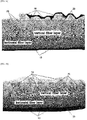
- a meltblown fiber web for use in the present invention comprises: a horizontal fiber layer 10 formed by allowing a portion of meltblown microfibers to reach a low-velocity collection portion and to be deposited on the low-velocity collection portion in a horizontal orientation; a serpentine vertical fiber layer 20 formed by allowing the other portion of the meltblown microfibers to reach a high-velocity collection portion having a surface velocity higher than that of the low-velocity collection portion; and a waved layer 30 formed by entanglement of the microfibers at the top of the vertical fiber layer 20, the waved layer forming the uppermost portion of the fiber web.
- the present invention concerns the use of a waved meltblown fiber web as defined in claim 1.
- meltblown fiber webs and production methods thereof developed to date, there is a limit to the production of a fiber web which has a lower density, is bulky, and has a dense internal structure, and the compressive modulus and sound absorption performance of the meltblown fiber webs are also not satisfactory.
- An object of the present invention is to overcome the existing limitation, and the present inventors have conducted studies for many years, and as a result, have developed a meltblown fiber web which has a lower density, is more bulky, and has a dense internal structure and increased compressive modulus and sound absorption performance, compared to conventional products, and an easy method for producing the meltblown fiber web.
- the meltblown fiber web for use in the present invention is more bulky and has excellent elasticity and a dense internal structure, compared to conventional meltblown fiber webs, and the properties thereof can be more easily controlled.
- meltblown fiber web which is more bulky and has excellent elasticity and a dense internal structure.
- meltblown fiber webs having various properties can be easily produced by changing the deposition pattern of meltblown microfibers by the manufacturer to control the bonding strength and twisting patterns of the microfibers, the elasticity, density and volume of the fiber web, and the like.
- FIGS. 1 a and 1b show the cross-sectional structure of a waved meltblown fiber web according to an embodiment of the present invention
- FIGS. 2a , 2b and 2c show the structure of the top of a waved meltblown fiber web according to an embodiment of the present invention
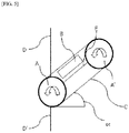
- FIG. 3 shows a method for producing a waved meltblown fiber web according to an embodiment of the present invention
- FIG. 4 shows the control of the ratio between a horizontal fiber layer and a vertical fiber layer in a method for producing a waved meltblown fiber web according to an embodiment of the present invention
- FIG. 1 a and 1b show the cross-sectional structure of a waved meltblown fiber web according to an embodiment of the present invention
- FIGS. 2a , 2b and 2c show the structure of the top of a waved meltblown fiber web according to an embodiment of the present invention
- FIG. 3 shows a method for producing a waved meltblown fiber web according to an embodiment of the present invention
- FIG. 4 shows the control of the ratio between a
- FIG. 5 shows an apparatus for producing a waved meltblown fiber web according to an embodiment of the present invention
- FIG. 6 is a flow chart showing a method for producing a waved meltblown fiber web according to an embodiment of the present invention
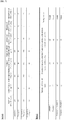
- FIG. 7 shows the results of tests for Example 1, Example 2, Comparative Example 1 and Comparative Example 2
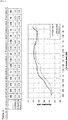
- FIG. 8 shows the results of testing the sound absorption properties of Example 1 and Comparative Example 1
- FIG. 9 shows the results of testing the sound absorption properties of Example 2 and Comparative Example 2.
- the present invention relates to a fiber web produced by allowing meltblown fibers to reach collection portions having different surface velocities (the velocities of regions to which the meltblown microfibers come) so as to form structures having dual properties.
- the collection portions include a high-velocity collection portion and a low-velocity collection portion, and "high-velocity” and “low-velocity” have relative concepts, and are intended to mean that the surfaces (the surfaces to which the fibers come) have different velocities.
- the high-velocity collection portion or the low-velocity collection portion is intended to include a surface that is rotated by a circular roller, or a belt-type collection portion that moves in a plane.
- the term "collection portion” refers to a unit having a portion to which the meltblown microfibers come, and means a region which moves while the meltblown fibers are deposited thereon.
- the left side of a collector 7 functions as the low-velocity collection portion
- a deposition pattern change unit 6 functions as the high-velocity collection portion.
- high velocity and low velocity have relative concepts, and are merely intended to mean that the surface velocity of the high-velocity collection portion is higher than the surface velocity of the low-velocity collection portion.
- these terms “high velocity” and “low velocity” do not mean quantitative absolute values, and it does not appear that these terms make the present invention obscure.
- the waved meltblown fiber web for use in the present invention is characterized in that it is produced by a method in which meltblown microfibers are collected by bringing them into contact with collection portions having different surface velocities.
- the waved meltblown fiber web for use in the present invention comprises a horizontal fiber layer 10, a vertical fiber layer 20 and a waved layer 30.
- a portion of meltblown microfibers reach a low-velocity collection portion on which the microfibers are deposited in a horizontal orientation to form a horizontal fiber layer 10
- the other portion of meltblown microfibers reach a high-velocity collection portion having a surface velocity higher than that of the low-velocity collection portion to form a serpentine vertical fiber layer 20.
- the fibers at the top of the vertical fiber layer 20 are entangled with one another to form a waved layer 30 that forms the uppermost portion of the fiber web.
- the waved layer 30 is preferably configured such that the lines defined by the peaks and valleys of the wave are arranged at irregular intervals in a horizontal direction(in anterioposterial direction and lengthways).
- the waved layer 30 is preferably separated on the whole from the vertical fiber layer 20 when one side of the waved layer 30 is pulled.
- the waved meltblown fiber web for use in the present invention preferably further comprises staple fibers which serve to intertangle the meltblown microfibers together.
- the waved meltblown fiber web preferably further comprises a covering fabric 40 covering the meltblown fiber web, and the covering fabric 40 is a nonwoven fabric made of spunbond fibers.
- the ratio of the thickness of the horizontal fiber layer 10 to the thickness of the vertical fiber layer 20 is preferably 1:1 to 1: 9 in a state in which an external compressive load is not applied to the fiber web and the fiber web is freely spread out, or in a state in which an external compressive load is not applied to the fiber web and the fiber web is covered with the covering fabric 40 and is freely spread out, or in a state in which the fiber web is pulled up upwardly by an external force 0.1-2 times the total thickness of the fiber web in a load-free state.
- the content of the staple fibers in the multilayer meltblown fiber web is preferably 5-90 wt% based on the total weight of the meltblown fiber web in a state in which the meltblown fiber web is not covered with the covering fabric 40.
- the staple fibers are preferably mesofibers such as olefinic polypropylene (PP) fibers, polyethylene (PE) fibers, polyethylene terephthalate (PET) fibers, or amide-based nylon fibers.
- the staple fibers are mesofibers either selected from the group consisting of synthetic polymer fibers, including olefinic polypropylene (PP) fibers, polyethylene (PE) fibers, polyethylene terephthalate (PET) fibers, amide-based nylon fibers, glass fibers, and carbon-based fibers, or selected from the group consisting of natural polymer fibers, including cotton fibers, hemp fibers and pulp fibers.
- the staple fibers are mesofibers selected from among staple fibers , hollow fibers, multi-lobal fibers, and electrostatically treated staple fibers.
- the method of producing the meltblown fiber web by the melt-blown method according to the present invention is characterized in that meltblown microfibers are collected by bringing them into contact with collection portions having different surface velocities.
- the method of producing the meltblown fiber web by the melt-blown method preferably comprises the steps of: (S1) feeding a thermoplastic resin composition into an extruder; (S2) extruding the thermoplastic resin composition; (S3) spinning the extruded thermoplastic resin composition with a high-temperature and high-pressure gas in the form of filaments; (S4) depositing a portion of the spun filaments on a low-velocity collection portion in a single orientation and in a predetermined pattern to form a horizontal fiber layer 10, and bringing the other portion of the spun filaments into contact with a high-velocity collection portion to form a vertical fiber layer 20; and (S5) winding the produced meltblown fiber web.
- thermoplastic resin refers to a resin that can repeatedly be melted at a temperature higher than the melting point of the polymer resin and solidified by cooling.
- the thermoplastic resins can be divided, according to the degree of crystallization, crystalline thermoplastic resins and amorphous thermoplastic resins.
- the crystalline thermoplastic resins include polyethylene, polypropylene, nylon and the like, and the amorphous thermoplastic resins include polyvinyl chloride, polystyrene and the like.
- polyolefin is intended to mean any of a series of saturated open-chain polymeric hydrocarbons composed only of carbon and hydrogen atoms.
- Typical polyolefins include polyethylene, polypropylene, polymethylpentene, and various combinations of ethylene, propylene and methylpentene monomers.
- polypropylene as used herein is intended to encompass not only homopolymers of propylene, but also copolymers wherein at least 40% of the recurring units are propylene units.
- polyester as used herein is intended to embrace polymers wherein at least 85% of the recurring units are condensation products of dicarboxylic acids and dihydroxy alcohols with polymer linkages created by formation of ester units. This includes aromatic, aliphatic, saturated, and unsaturated di-acids and di-alcohols.
- polymers as used herein also includes copolymers, blends, and modifications thereof.
- a common example of a polyester is poly(ethylene terephthalate) (PET) which is a condensation product of ethylene glycol and terephthalic acid.
- meltblown microfibers or “meltblown filaments” as used herein means the fibers or filaments formed by extruding a molten processible polymer through a plurality of fine capillaries into a high-temperature and high-velocity gas.
- the capillaries may have various shapes, including polygonal shapes such as circular, triangular and square shapes, and a star shape.
- the high-temperature and high-velocity gas can attenuate the filaments of molten thermoplastic polymer material to reduce their diameter to about 0.3-10 ⁇ m.
- the meltblown fibers may be discontinuous fibers or continuous fibers. 70-80% or 90% of the meltblown microfibers may have a diameter of 10 ⁇ m or less. Further, 10%, 20% or 30% of the meltblown microfibers may have a diameter of 3 ⁇ m or less.
- spunbond fibers means a fiber web produced by extruding a molten polymer material through a plurality of fine capillaries to form filaments and drawing the filaments through high-temperature tubes.
- the spunbond fibers are continuous in the lengthwise direction of the filaments, and the filaments have an average diameter greater than about 5 ⁇ m.
- a meltblown fiber web was produced according to the production method of the present invention as shown in FIG. 3 .
- Specific conditions for the production of the meltblown fiber web are as follows.
- thermoplastic resin composition 1 comprising 99.8 wt% of homopolypropylene H7914 polymer resin (LG Chemical Ltd.) having a melt index of 1400 (230°C, g/10 min), 0.1 wt% of UV stabilizer Tinuvin 622 (Ciba Special Chemical) and 0.1 wt% of thermal stabilizer Irganox 1010 was fed into an extruder 2.
- the single extruder having a length/dimension ratio of 1/28 was rotated at 80 rpm to knead, heat and extrude the thermoplastic resin composition 1.
- the fibers were spun in the direction of collectors through 32 orifices (orifice diameter: 0.2 mm) per inch in a spinning die having a diameter of 2 m.
- the fibers were allowed to collide with a high-temperature and high-velocity gas injected from high-temperature and high-velocity gas injection holes 4A and 4B disposed symmetrically on the left and right sides in the spinning die 3, thereby producing meltblown microfibers.
- the vertical distance between the spinning die 3 and the collector 7 was set at 70 cm, and the surface velocity of the collector 7 was 2.5 m/min, and under such conditions, 200 g/m 2 of meltblown fibers were produced.
- 50 wt% of the meltblown microfibers 5 spun from the spinning die 3 were transferred directly to the collector 7 without passing through a deposition pattern change unit 6, and was deposited on the collector in a horizontal orientation.
- 50 wt% of the meltblown microfibers 5 spun from the spinning die 3 were passed through the deposition pattern change unit 6 of the present invention to change the orientation of the microfibers 5 to a vertical orientation and was deposited on a top of the horizontally oriented meltblown fiber web in a vertical orientation.
- Both sides of 200 g/m 2 of the meltblown fiber web produced as described above were laminated with 15 g/m 2 of a spunbond nonwoven fabric, thereby producing a meltblown fiber web having a total weight of 230 g/m 2 .
- the operating conditions of the deposition pattern change unit used in this Example are as follows.
- the deposition pattern change unit used in this Example was composed of a steel roll A having a length of 2,200 mm and a diameter of 100 pi, a steel roll A' having the same size as that of the steel roll A, and a stainless steel mesh belt C connected to the rolls and having a diameter of 2,100 mm.
- the distance E between the steel roll A and the steel roll A' was 400 mm, and the steel roll A and the steel roll A' were rotated in the same direction, at the same velocity, as shown in FIG. 5 .
- the inside of the stainless steel mesh belt C of the deposition pattern change unit 6 includes the absorption member B configured to absorb the high-temperature and high-pressure gas injected from the spinning die.
- the distance D between the deposition pattern change unit 6 and the spinning die 3 was set at 35 cm, and the distance D' between the deposition pattern change unit 6 and the collector 7 was set at 25 cm.
- the deposition pattern change unit 6 was disposed at a position at which it could collect 50 wt% of the meltblown microfibers 5 spun from the spinning die 3.
- FIGS. 1a and 1b are cross-sectional views of the meltblown fiber web produced in Example 1.
- the thickness, weight, compressive modulus and sound absorption coefficient of the meltblown fiber web produced in the Example were measured.
- the thickness of the fiber web was measured in accordance with 5.3 of Internal Standard ISO 9073-2.
- the weights of five samples having a size of 100 mm x 100 mm were measured and averaged. Then, the average value was expressed as a representative value.
- the compressive modulus of the fiber web was measured in accordance with 4.8 of MS341-17, and the sound absorption performance of the fiber web was measured in accordance with the reverberation chamber method of the technical standard GM 14177.
- a mite avoidance test for the fiber web was performed in accordance with the passing test method of FC-TM-21.
- the thickness (10HD) and weight of the horizontally deposited meltblown fiber web (10AH) as shown in FIG. 1a are 5 mm and 100 g/m 2 , respectively.
- the thickness (10VD) and weight of the horizontally deposited meltblown fiber web (10AV) are 8 mm and 100 g/m 2 , respectively.
- Example 2 Fiber web including staple fibers
- thermoplastic resin composition 1 comprising 99.8 wt% of homopolypropylene H7914 polymer resin (LG Chemical Ltd.) having a melt index of 1400 (230°C, g/10 min), 0.1 wt% of UV stabilizer Tinuvin 622 (Ciba Special Chemical) and 0.1 wt% of thermal stabilizer Irganox 1010 was fed into an extruder 2.
- the single extruder having a length/dimension ratio of 1/28 was rotated at 80 rpm to knead, heat and extrude the thermoplastic resin composition 1.
- the fibers were spun in the direction of collectors through 32 orifices (orifice diameter: 0.2 mm) per inch in a spinning die having a diameter of 2 m.
- the fibers were allowed to collide with a high-temperature and high-velocity gas injected from high-temperature and high-velocity gas injection holes 4A and 4B disposed symmetrically on the left and right sides in the spinning die 3, thereby producing meltblown microfibers.
- a staple fiber feeding unit was provided at a distance of 10 cm from the spinning die 3 in the direction of the collector 7, and polypropylene staple fibers having a diameter of 40 ⁇ m and an average length of 39 mm were added to the meltblown microfibers 5 in an amount of 20 wt% based on the total weight of the fiber web.
- the vertical distance between the spinning die 3 and the collector 7 was set at 70 cm, and the surface velocity of the collector 7 was 2 m/min, and under such conditions, 200 g/m 2 of meltblown fibers were produced. 50 wt% of the meltblown microfibers 5 spun from the spinning die 3 were transferred directly to the collector 7 without passing through a deposition pattern change unit 6, and was deposited on the collector in a horizontal orientation.
- meltblown microfibers 5 spun from the spinning die 3 were passed through the deposition pattern change unit 6 of the present invention to change the orientation of the microfibers 5 to a vertical orientation and was deposited on a top of the horizontally oriented meltblown fiber web in a vertical orientation.
- Both sides of 200 g/m 2 of the meltblown fiber web produced as described above were laminated with 15 g/m 2 of a spunbond nonwoven fabric, thereby producing a meltblown fiber web having a total weight of 230 g/m 2 .
- meltblown fiber web was produced in the same manner as described in Example 1, except that the deposition pattern change unit 6 of the present invention was not used and the meltblown microfibers 5 spun from the spinning die 3 were all deposited on the collector in a horizontal orientation. Both sides of the meltblown fiber web were laminated with 15 g/m 2 of a spunbond nonwoven fabric (covering fabric), thereby producing a meltblown fiber web having a total weight of 230 g/m 2 .
- meltblown fiber web was produced in the same manner as described in Example 2, except that the deposition pattern change unit 6 of the present invention was not used and the meltblown microfibers 5 spun from the spinning die 3 were all deposited on the collector in a horizontal orientation. Both sides of the meltblown fiber web were laminated with 15 g/m 2 of a spunbond nonwoven fabric (covering fabric), thereby producing a meltblown fiber web having a total weight of 230 g/m 2
- FIG. 7 shows the results of tests for Example 1, Example 2, Comparative Example 1 and Comparative Example 2;
- FIG. 8 shows the results of testing the sound absorption properties of Example 1 and Comparative Example 1;
- FIG. 9 shows the results of testing the sound absorption properties of Example 2 and Comparative Example 2.
- Table 1 in FIG. 7 shows the results of measuring the thicknesses and weights of the meltblown fiber webs produced in Example 1, Example 2, Comparative Example 1 and Comparative Example 2.
- Table 2 in FIG. 7 shows the results of measuring the compressive modulus the fiber webs of Example 1, Example 2, Comparative Example 1 and Comparative Example 2 under heat resistant and moisture resistant conditions, and the results of performing the anti-fungal test for the fiber webs.
- the fiber webs of Example 1 and Example 2 did not pass mites in the mite test, but the fiber webs of Comparative Examples 1 and 2 failed in the mite test. This is because the internal structure of the meltblown fiber web composed of a composition of the horizontally deposited structure and the vertically deposited structure according to the present invention was denser than the internal structure of the fiber webs of Comparative Examples 1 and 2 composed only of the horizontally deposited structure.
- Table 3 in FIG. 8 shows the results of measuring the sound absorption performance of the fiber webs of Example 1 and Comparative Example 1
- Table 4 in FIG. 9 shows the results of measuring the sound absorption performance of the fiber webs of Example 2 and Comparative Example 2.
- the fiber web of Example 1 showed excellent sound absorption performance compared to the fiber web of Comparative Example 1
- the fiber web of Example 2 showed excellent sound absorption performance compared to the fiber web of Comparative Example 2. This is because the meltblown fiber web composed of a composition of the horizontally deposited structure and the vertically deposited structure according to the present invention had a denser internal structure and was more bulky, compared to the fiber webs of Comparative Examples 1 and 2 composed only of the horizontally deposited structure.
- meltblown fiber web which is more bulky and has excellent compressive modulus and a denser internal structure, compared to meltblown fiber webs produced by conventional production methods.
Landscapes
- Engineering & Computer Science (AREA)
- Textile Engineering (AREA)
- Mechanical Engineering (AREA)
- Nonwoven Fabrics (AREA)
Description
- The present invention relates to the use of a meltblown fiber web having a bilayer structure, and produced by a melt-blown method for making sound absorption and sound insulation materials having sound absorption property against sound ranging from 400 Hz to 10.000 Hz in vehicles.
- Korean Patent Application No.
10-2010-7000497 (May 7, 2008 -
US Patent No. 4, 1118, 531 (filing date: November 4, 1977 - International Patent Application
PCT/US94/09277 PCT/US94/09277 - The present invention concerns the use of a meltblown fiber web for making a sound absorption and sound insulation material which has excellent sound insulation and absorption properties against noise occurring inside internal combustion engine vehicles, and which is light in weight per unit volume so as to be able to increase the energy efficiency of vehicles, and discloses a method for producing the meltblown fiber web.
- In addition, the present invention concerns the use of a meltblown fiber web for making a sound absorption and sound insulation material, which has improved sound absorption and soundproofing performance in the low-frequency range (200-800 Hz) of vehicle indoor noise, compared to conventional sound absorption and soundproofing materials, and the noise reduction frequency range of which can be controlled by controlling air permeability and design factors depending the needs of the user (car company), and discloses a method for producing the meltblown fiber web.
- A waved meltblown fiber web for use in the present invention is produced by a melt-blown method which comprises collecting meltblown microfibers by bringing them into contact with collection portions having different surface velocities.
- A meltblown fiber web for use in the present invention comprises: a
horizontal fiber layer 10 formed by allowing a portion of meltblown microfibers to reach a low-velocity collection portion and to be deposited on the low-velocity collection portion in a horizontal orientation; a serpentinevertical fiber layer 20 formed by allowing the other portion of the meltblown microfibers to reach a high-velocity collection portion having a surface velocity higher than that of the low-velocity collection portion; and a wavedlayer 30 formed by entanglement of the microfibers at the top of thevertical fiber layer 20, the waved layer forming the uppermost portion of the fiber web. - More precisely, the present invention concerns the use of a waved meltblown fiber web as defined in
claim 1. - In meltblown fiber webs and production methods thereof, developed to date, there is a limit to the production of a fiber web which has a lower density, is bulky, and has a dense internal structure, and the compressive modulus and sound absorption performance of the meltblown fiber webs are also not satisfactory. An object of the present invention is to overcome the existing limitation, and the present inventors have conducted studies for many years, and as a result, have developed a meltblown fiber web which has a lower density, is more bulky, and has a dense internal structure and increased compressive modulus and sound absorption performance, compared to conventional products, and an easy method for producing the meltblown fiber web. The meltblown fiber web for use in the present invention is more bulky and has excellent elasticity and a dense internal structure, compared to conventional meltblown fiber webs, and the properties thereof can be more easily controlled.
- According to the present invention, it is possible to produce a meltblown fiber web which is more bulky and has excellent elasticity and a dense internal structure. In addition, meltblown fiber webs having various properties can be easily produced by changing the deposition pattern of meltblown microfibers by the manufacturer to control the bonding strength and twisting patterns of the microfibers, the elasticity, density and volume of the fiber web, and the like.
- Specifically, the effects of the present invention are as follows.
- 1. According to the present invention, a meltblown fiber web having lower density, larger volume and higher compressive modulus can be provided to the market.
- 2. A meltblown fiber web having better sound absorption performance and a denser internal structure can be provided to the marker. In addition, a meltblown fiber web, which has a denser structure leading to an enhanced anti-mite property, can be provided to the market.
- 3. Meltblown fiber webs having various densities, elasticities and internal structures can be easily produced by controlling the pattern and deposition amount of a horizontally oriented meltblown microfiber layer and a vertically oriented meltblown microfiber layer. In other words, meltblown fiber webs having various densities, elasticities and internal structures can be easily produced by repeatedly depositing a horizontally oriented meltblown microfiber layer and a vertically oriented meltblown microfiber layer.
-
-
FIGS. 1a and 1b show the cross-sectional structure of a waved meltblown fiber web according to an embodiment of the present invention. -
FIGS. 2a ,2b and2c show the structure of the top of a waved meltblown fiber web according to an embodiment of the present invention. -
FIG. 3 shows a method for producing a waved meltblown fiber web according to an embodiment of the present invention. -
FIG. 4 shows the control of the ratio between a horizontal fiber layer and a vertical fiber layer in a method for producing a waved meltblown fiber web according to an embodiment of the present invention. -
FIG. 5 shows an apparatus for producing a waved meltblown fiber web according to an embodiment of the present invention. -
FIG. 6 is a flow chart showing a method for producing a waved meltblown fiber web according to an embodiment of the present invention. -
FIG. 7 shows the results of tests for Example 1, Example 2, Comparative Example 1 and Comparative Example 2. -
FIG. 8 shows the results of testing the sound absorption properties of Example 1 and Comparative Example 1. -
FIG. 9 shows the results of testing the sound absorption properties of Example 2 and Comparative Example 2. - Hereinafter, a waved meltblown fiber web according to an embodiment of the present invention and a method for producing the same will be described in detail with reference to the accompanying drawings.
FIGS. 1 a and 1b show the cross-sectional structure of a waved meltblown fiber web according to an embodiment of the present invention;FIGS. 2a ,2b and2c show the structure of the top of a waved meltblown fiber web according to an embodiment of the present invention;FIG. 3 shows a method for producing a waved meltblown fiber web according to an embodiment of the present invention;FIG. 4 shows the control of the ratio between a horizontal fiber layer and a vertical fiber layer in a method for producing a waved meltblown fiber web according to an embodiment of the present invention;FIG. 5 shows an apparatus for producing a waved meltblown fiber web according to an embodiment of the present invention;FIG. 6 is a flow chart showing a method for producing a waved meltblown fiber web according to an embodiment of the present invention;FIG. 7 shows the results of tests for Example 1, Example 2, Comparative Example 1 and Comparative Example 2;FIG. 8 shows the results of testing the sound absorption properties of Example 1 and Comparative Example 1; andFIG. 9 shows the results of testing the sound absorption properties of Example 2 and Comparative Example 2. - The present invention relates to a fiber web produced by allowing meltblown fibers to reach collection portions having different surface velocities (the velocities of regions to which the meltblown microfibers come) so as to form structures having dual properties. Herein, the collection portions include a high-velocity collection portion and a low-velocity collection portion, and "high-velocity" and "low-velocity" have relative concepts, and are intended to mean that the surfaces (the surfaces to which the fibers come) have different velocities. In the present invention, the high-velocity collection portion or the low-velocity collection portion is intended to include a surface that is rotated by a circular roller, or a belt-type collection portion that moves in a plane. As used herein, the term "collection portion" refers to a unit having a portion to which the meltblown microfibers come, and means a region which moves while the meltblown fibers are deposited thereon.
- In an embodiment of the present invention as shown in
FIG. 3 , the left side of acollector 7 functions as the low-velocity collection portion, and a deposition pattern change unit 6 functions as the high-velocity collection portion. Herein, terms "high velocity" and "low velocity" have relative concepts, and are merely intended to mean that the surface velocity of the high-velocity collection portion is higher than the surface velocity of the low-velocity collection portion. In addition, these terms "high velocity" and "low velocity" do not mean quantitative absolute values, and it does not appear that these terms make the present invention obscure. - As shown in
FIGS. 1a to 4 , the waved meltblown fiber web for use in the present invention is characterized in that it is produced by a method in which meltblown microfibers are collected by bringing them into contact with collection portions having different surface velocities. - As shown in
FIGS. 1a to 2c , the waved meltblown fiber web for use in the present invention comprises ahorizontal fiber layer 10, avertical fiber layer 20 and a wavedlayer 30. In the waved meltblown fiber web according to the present invention, a portion of meltblown microfibers reach a low-velocity collection portion on which the microfibers are deposited in a horizontal orientation to form ahorizontal fiber layer 10, and the other portion of meltblown microfibers reach a high-velocity collection portion having a surface velocity higher than that of the low-velocity collection portion to form a serpentinevertical fiber layer 20. The fibers at the top of thevertical fiber layer 20 are entangled with one another to form a wavedlayer 30 that forms the uppermost portion of the fiber web. - In the waved meltblown fiber web for use in the present invention, as shown in
FIG. 2a , the wavedlayer 30 is preferably configured such that the lines defined by the peaks and valleys of the wave are arranged at irregular intervals in a horizontal direction(in anterioposterial direction and lengthways). - In the waved meltblown fiber web for use in the present invention, as shown in
FIG. 2b , the wavedlayer 30 is preferably separated on the whole from thevertical fiber layer 20 when one side of the wavedlayer 30 is pulled. - The waved meltblown fiber web for use in the present invention preferably further comprises staple fibers which serve to intertangle the meltblown microfibers together. As shown in
FIG. 1b , the waved meltblown fiber web preferably further comprises a coveringfabric 40 covering the meltblown fiber web, and the coveringfabric 40 is a nonwoven fabric made of spunbond fibers. - In the waved meltblown fiber web for use in the present invention, the ratio of the thickness of the
horizontal fiber layer 10 to the thickness of thevertical fiber layer 20 is preferably 1:1 to 1: 9 in a state in which an external compressive load is not applied to the fiber web and the fiber web is freely spread out, or in a state in which an external compressive load is not applied to the fiber web and the fiber web is covered with the coveringfabric 40 and is freely spread out, or in a state in which the fiber web is pulled up upwardly by an external force 0.1-2 times the total thickness of the fiber web in a load-free state. - In the waved meltblown fiber web according to the present invention, the content of the staple fibers in the multilayer meltblown fiber web is preferably 5-90 wt% based on the total weight of the meltblown fiber web in a state in which the meltblown fiber web is not covered with the covering
fabric 40. The staple fibers are preferably mesofibers such as olefinic polypropylene (PP) fibers, polyethylene (PE) fibers, polyethylene terephthalate (PET) fibers, or amide-based nylon fibers. The staple fibers are mesofibers either selected from the group consisting of synthetic polymer fibers, including olefinic polypropylene (PP) fibers, polyethylene (PE) fibers, polyethylene terephthalate (PET) fibers, amide-based nylon fibers, glass fibers, and carbon-based fibers, or selected from the group consisting of natural polymer fibers, including cotton fibers, hemp fibers and pulp fibers. In addition, in the present invention, the staple fibers are mesofibers selected from among staple fibers , hollow fibers, multi-lobal fibers, and electrostatically treated staple fibers. - As shown in
FIGS. 3 ,4 and6 , the method of producing the meltblown fiber web by the melt-blown method according to the present invention is characterized in that meltblown microfibers are collected by bringing them into contact with collection portions having different surface velocities. - As shown in
FIGS. 3 ,4 and6 , the method of producing the meltblown fiber web by the melt-blown method preferably comprises the steps of: (S1) feeding a thermoplastic resin composition into an extruder; (S2) extruding the thermoplastic resin composition; (S3) spinning the extruded thermoplastic resin composition with a high-temperature and high-pressure gas in the form of filaments; (S4) depositing a portion of the spun filaments on a low-velocity collection portion in a single orientation and in a predetermined pattern to form ahorizontal fiber layer 10, and bringing the other portion of the spun filaments into contact with a high-velocity collection portion to form avertical fiber layer 20; and (S5) winding the produced meltblown fiber web. - As used herein, the term "thermoplastic resin" refers to a resin that can repeatedly be melted at a temperature higher than the melting point of the polymer resin and solidified by cooling. The thermoplastic resins can be divided, according to the degree of crystallization, crystalline thermoplastic resins and amorphous thermoplastic resins. The crystalline thermoplastic resins include polyethylene, polypropylene, nylon and the like, and the amorphous thermoplastic resins include polyvinyl chloride, polystyrene and the like.
- As used herein, the term "polyolefin" is intended to mean any of a series of saturated open-chain polymeric hydrocarbons composed only of carbon and hydrogen atoms. Typical polyolefins include polyethylene, polypropylene, polymethylpentene, and various combinations of ethylene, propylene and methylpentene monomers.
- The term "polypropylene" as used herein is intended to encompass not only homopolymers of propylene, but also copolymers wherein at least 40% of the recurring units are propylene units.
- The term "polyester" as used herein is intended to embrace polymers wherein at least 85% of the recurring units are condensation products of dicarboxylic acids and dihydroxy alcohols with polymer linkages created by formation of ester units. This includes aromatic, aliphatic, saturated, and unsaturated di-acids and di-alcohols. The term "polyester" as used herein also includes copolymers, blends, and modifications thereof. A common example of a polyester is poly(ethylene terephthalate) (PET) which is a condensation product of ethylene glycol and terephthalic acid.
- The term "meltblown microfibers" or "meltblown filaments" as used herein means the fibers or filaments formed by extruding a molten processible polymer through a plurality of fine capillaries into a high-temperature and high-velocity gas. Herein, the capillaries may have various shapes, including polygonal shapes such as circular, triangular and square shapes, and a star shape. In addition, for example, the high-temperature and high-velocity gas can attenuate the filaments of molten thermoplastic polymer material to reduce their diameter to about 0.3-10 µm. The meltblown fibers may be discontinuous fibers or continuous fibers. 70-80% or 90% of the meltblown microfibers may have a diameter of 10 µm or less. Further, 10%, 20% or 30% of the meltblown microfibers may have a diameter of 3 µm or less.
- As used herein, the term "spunbond fibers" means a fiber web produced by extruding a molten polymer material through a plurality of fine capillaries to form filaments and drawing the filaments through high-temperature tubes. The spunbond fibers are continuous in the lengthwise direction of the filaments, and the filaments have an average diameter greater than about 5 µm.
- A meltblown fiber web was produced according to the production method of the present invention as shown in
FIG. 3 . Specific conditions for the production of the meltblown fiber web are as follows. - A
thermoplastic resin composition 1 comprising 99.8 wt% of homopolypropylene H7914 polymer resin (LG Chemical Ltd.) having a melt index of 1400 (230°C, g/10 min), 0.1 wt% of UV stabilizer Tinuvin 622 (Ciba Special Chemical) and 0.1 wt% of thermal stabilizer Irganox 1010 was fed into anextruder 2. - The single extruder having a length/dimension ratio of 1/28 was rotated at 80 rpm to knead, heat and extrude the
thermoplastic resin composition 1. Next, the fibers were spun in the direction of collectors through 32 orifices (orifice diameter: 0.2 mm) per inch in a spinning die having a diameter of 2 m. At the same time, the fibers were allowed to collide with a high-temperature and high-velocity gas injected from high-temperature and high-velocitygas injection holes - The vertical distance between the spinning die 3 and the
collector 7 was set at 70 cm, and the surface velocity of thecollector 7 was 2.5 m/min, and under such conditions, 200 g/m2 of meltblown fibers were produced. 50 wt% of the meltblown microfibers 5 spun from the spinning die 3 were transferred directly to thecollector 7 without passing through a deposition pattern change unit 6, and was deposited on the collector in a horizontal orientation. Meanwhile, 50 wt% of the meltblown microfibers 5 spun from the spinning die 3 were passed through the deposition pattern change unit 6 of the present invention to change the orientation of the microfibers 5 to a vertical orientation and was deposited on a top of the horizontally oriented meltblown fiber web in a vertical orientation. - Both sides of 200 g/m2 of the meltblown fiber web produced as described above were laminated with 15 g/m2 of a spunbond nonwoven fabric, thereby producing a meltblown fiber web having a total weight of 230 g/m2.
- The operating conditions of the deposition pattern change unit used in this Example are as follows. The deposition pattern change unit used in this Example was composed of a steel roll A having a length of 2,200 mm and a diameter of 100 pi, a steel roll A' having the same size as that of the steel roll A, and a stainless steel mesh belt C connected to the rolls and having a diameter of 2,100 mm. The distance E between the steel roll A and the steel roll A' was 400 mm, and the steel roll A and the steel roll A' were rotated in the same direction, at the same velocity, as shown in
FIG. 5 . In addition, the inside of the stainless steel mesh belt C of the deposition pattern change unit 6 includes the absorption member B configured to absorb the high-temperature and high-pressure gas injected from the spinning die. The distance D between the deposition pattern change unit 6 and the spinning die 3 was set at 35 cm, and the distance D' between the deposition pattern change unit 6 and thecollector 7 was set at 25 cm. In addition, the deposition pattern change unit 6 was disposed at a position at which it could collect 50 wt% of the meltblown microfibers 5 spun from the spinning die 3. -
FIGS. 1a and 1b are cross-sectional views of the meltblown fiber web produced in Example 1. The thickness, weight, compressive modulus and sound absorption coefficient of the meltblown fiber web produced in the Example were measured. The thickness of the fiber web was measured in accordance with 5.3 of Internal Standard ISO 9073-2. For measurement of the weight, the weights of five samples having a size of 100 mm x 100 mm were measured and averaged. Then, the average value was expressed as a representative value. - The compressive modulus of the fiber web was measured in accordance with 4.8 of MS341-17, and the sound absorption performance of the fiber web was measured in accordance with the reverberation chamber method of the technical standard GM 14177. In addition, a mite avoidance test for the fiber web was performed in accordance with the passing test method of FC-TM-21. The thickness (10HD) and weight of the horizontally deposited meltblown fiber web (10AH) as shown in
FIG. 1a are 5 mm and 100 g/m2, respectively. In addition, the thickness (10VD) and weight of the horizontally deposited meltblown fiber web (10AV) are 8 mm and 100 g/m2, respectively. - A
thermoplastic resin composition 1 comprising 99.8 wt% of homopolypropylene H7914 polymer resin (LG Chemical Ltd.) having a melt index of 1400 (230°C, g/10 min), 0.1 wt% of UV stabilizer Tinuvin 622 (Ciba Special Chemical) and 0.1 wt% of thermal stabilizer Irganox 1010 was fed into anextruder 2. - The single extruder having a length/dimension ratio of 1/28 was rotated at 80 rpm to knead, heat and extrude the
thermoplastic resin composition 1. Next, the fibers were spun in the direction of collectors through 32 orifices (orifice diameter: 0.2 mm) per inch in a spinning die having a diameter of 2 m. At the same time, the fibers were allowed to collide with a high-temperature and high-velocity gas injected from high-temperature and high-velocitygas injection holes - A staple fiber feeding unit was provided at a distance of 10 cm from the spinning die 3 in the direction of the
collector 7, and polypropylene staple fibers having a diameter of 40 µm and an average length of 39 mm were added to the meltblown microfibers 5 in an amount of 20 wt% based on the total weight of the fiber web. The vertical distance between the spinning die 3 and thecollector 7 was set at 70 cm, and the surface velocity of thecollector 7 was 2 m/min, and under such conditions, 200 g/m2 of meltblown fibers were produced. 50 wt% of the meltblown microfibers 5 spun from the spinning die 3 were transferred directly to thecollector 7 without passing through a deposition pattern change unit 6, and was deposited on the collector in a horizontal orientation. Meanwhile, 50 wt% of the meltblown microfibers 5 spun from the spinning die 3 were passed through the deposition pattern change unit 6 of the present invention to change the orientation of the microfibers 5 to a vertical orientation and was deposited on a top of the horizontally oriented meltblown fiber web in a vertical orientation. - Both sides of 200 g/m2 of the meltblown fiber web produced as described above were laminated with 15 g/m2 of a spunbond nonwoven fabric, thereby producing a meltblown fiber web having a total weight of 230 g/m2.
- A meltblown fiber web was produced in the same manner as described in Example 1, except that the deposition pattern change unit 6 of the present invention was not used and the meltblown microfibers 5 spun from the spinning die 3 were all deposited on the collector in a horizontal orientation. Both sides of the meltblown fiber web were laminated with 15 g/m2 of a spunbond nonwoven fabric (covering fabric), thereby producing a meltblown fiber web having a total weight of 230 g/m2.
- A meltblown fiber web was produced in the same manner as described in Example 2, except that the deposition pattern change unit 6 of the present invention was not used and the meltblown microfibers 5 spun from the spinning die 3 were all deposited on the collector in a horizontal orientation. Both sides of the meltblown fiber web were laminated with 15 g/m2 of a spunbond nonwoven fabric (covering fabric), thereby producing a meltblown fiber web having a total weight of 230 g/m2
-
FIG. 7 shows the results of tests for Example 1, Example 2, Comparative Example 1 and Comparative Example 2;FIG. 8 shows the results of testing the sound absorption properties of Example 1 and Comparative Example 1; andFIG. 9 shows the results of testing the sound absorption properties of Example 2 and Comparative Example 2. Table 1 inFIG. 7 shows the results of measuring the thicknesses and weights of the meltblown fiber webs produced in Example 1, Example 2, Comparative Example 1 and Comparative Example 2. Table 2 inFIG. 7 shows the results of measuring the compressive modulus the fiber webs of Example 1, Example 2, Comparative Example 1 and Comparative Example 2 under heat resistant and moisture resistant conditions, and the results of performing the anti-fungal test for the fiber webs. - From a comparison between the measurement results for the fiber webs of Example 1, Example 2, Comparative Example 1 and Comparative Example 2, as shown Tables 1 and 2 in
FIG. 7 , the effects of the present invention can be clearly found. It can be seen that, when the vertically oriented meltblown fiber web was deposited on a top of the horizontally deposited meltblown fiber web using the deposition pattern change unit of the present invention, the thickness per weight was increased by 30-41% compared to that of the fiber web composed only of the horizontally oriented fiber web. From a comparison between the measurement results for the compressive modulus of Example 1 and Comparative Example 1, it can be seen that the compressive modulus of the meltblown fiber web composed of a combination of the horizontally oriented fiber web and the vertically oriented fiber web was increased by 46% under heat resistant conditions and 10% under moisture resistant conditions, compared to the meltblown fiber web composed only of the horizontally oriented fiber web. - In addition, from a comparison between the measurement results for the compressive modulus of Example 2 and Comparative Example 2, in
FIG. 7 , it can be seen that the compressive modulus of the meltblown fiber web composed of a combination of the horizontally oriented fiber web and the vertically oriented fiber web was increased by 20% under heat resistant conditions and 10% under moisture resistant conditions, compared to the meltblown fiber web composed only of the horizontally oriented fiber web. Herein, it can be seen that the difference in compressive modulus under heat resistant conditions between Example 1 and Comparative Example 1 was significantly greater than the difference in compressive modulus under heat resistant conditions between Example 2 and Comparative Example 2. This appears to be because the addition of the polypropylene staple fibers increased the compressive modulus under heat conditions. - In addition, as can be seen in
FIG. 7 , the fiber webs of Example 1 and Example 2 did not pass mites in the mite test, but the fiber webs of Comparative Examples 1 and 2 failed in the mite test. This is because the internal structure of the meltblown fiber web composed of a composition of the horizontally deposited structure and the vertically deposited structure according to the present invention was denser than the internal structure of the fiber webs of Comparative Examples 1 and 2 composed only of the horizontally deposited structure. - Table 3 in
FIG. 8 shows the results of measuring the sound absorption performance of the fiber webs of Example 1 and Comparative Example 1, and Table 4 inFIG. 9 shows the results of measuring the sound absorption performance of the fiber webs of Example 2 and Comparative Example 2. As can be seen from the test results, the fiber web of Example 1 showed excellent sound absorption performance compared to the fiber web of Comparative Example 1, and the fiber web of Example 2 showed excellent sound absorption performance compared to the fiber web of Comparative Example 2. This is because the meltblown fiber web composed of a composition of the horizontally deposited structure and the vertically deposited structure according to the present invention had a denser internal structure and was more bulky, compared to the fiber webs of Comparative Examples 1 and 2 composed only of the horizontally deposited structure. Taken the results of the Examples and the Comparative Examples together, it can be seen that the use of the method for producing the meltblown fiber web according to the present invention enables the production of a meltblown fiber web, which is more bulky and has excellent compressive modulus and a denser internal structure, compared to meltblown fiber webs produced by conventional production methods. - As can be seen in
FIGS. 7 to 9 , the sound absorption and soundproofing properties of the meltblown fiber web for use in the present invention in an important frequency region of vehicle noise are improved. - Although the preferred embodiments of the present invention have been disclosed, the scope of the present invention is not limited to these embodiments, and covers various modifications and changes within the equivalent scope of the appended claims.
- It should be noted that reference numerals set forth in the appended claims are merely intended to aid in the understanding of the present invention, and are not intended to limit interpretation of the scope of the claims.
-
- 10 :
- horizontal fiber layer;
- 20 :
- vertical fiber layer;
- 30 :
- waved layer;
- 40 :
- covering fabric.
Claims (6)
- Use of a waved meltblown fiber web produced by a melt-blown method for making sound absorption and sound insulation materials having sound absorption property against sound ranging from 400 Hz to 10,000 Hz in vehicles, the meltblown fiber web comprising a horizontal fiber layer (10), a vertical fiber layer (20) formed on the horizontal fiber layer, and a waved layer (30) forming an uppermost portion of the vertical fiber layer (20),
wherein the horizontal fiber layer (10) is formed by allowing a portion of meltblown microfibers to reach a low-velocity collection portion and to be deposited on the low-velocity collection portion hereby the microfibers are in a horizontal orientation;
the vertical fiber layer (20) is formed in a serpentine shape of vertically oriented microfibers and deposited on the horizontal fiber layer after the horizontal fiber layer is deposited, by allowing the other portion of the meltblown microfibers to reach a high-velocity collection portion having a surface velocity higher than that of the low-velocity collection portion; and
the waved layer (30) is formed by entanglement of the microfibers at a top of the vertical fiber layer (20) and forms the uppermost portion of the fiber web; and 70% to 90% of the meltblown microfibers have a diameter of 10 µm or less and 10% to 30% of the meltblown microfibers have a diameter of 3 µm or less. - The use of claim 1, wherein the waved layer (30) is formed such that lines defined by peaks and valleys of the wave of the waved layer (30) are arranged at irregular intervals in a horizontal direction.
- The use of claim 1 or 2, wherein the waved meltblown fiber web further comprises staple fibers which serve to intertangle the meltblown microfibers together.
- The use according to any of claims 1 to 3, wherein the waved meltblown fiber web further comprises a covering fabric (40) covering the meltblown fiber web, in which the covering fabric (40) is a nonwoven fabric made of spunbond fibers.
- The use of claim 3 or 4, wherein the staple fibers are present in an amount of 5-90 wt% based on the total weight of the waved meltblown fiber web in a state in which the fiber web is not covered with the covering fabric (40).
- The use according to any of claims 3 to 5, wherein the staple fibers are mesofibers which are either synthetic polymer fibers selected from the group consisting of olefinic fibers such as polypropylene fibers, polyethylene fibers, polyethylene terephthalate fibers, nylon fibers, glass fibers, and carbon-based fibers, or natural polymer fibers selected from the group consisting of cotton fibers, hemp fibers and pulp fibers; or
the staple fibers are mesofibers selected from among staple fibers, hollow fibers, multi-lobal fibers, and electrostatically treated staple fibers, and have a dual structure.
Applications Claiming Priority (2)
| Application Number | Priority Date | Filing Date | Title |
|---|---|---|---|
| KR1020120125016A KR101308502B1 (en) | 2012-11-06 | 2012-11-06 | Melt blown fiber web and and producing method |
| PCT/KR2013/009354 WO2014073802A1 (en) | 2012-11-06 | 2013-10-18 | Waved meltblown fiber web and preparation method therefor |
Publications (3)
| Publication Number | Publication Date |
|---|---|
| EP2918718A1 EP2918718A1 (en) | 2015-09-16 |
| EP2918718A4 EP2918718A4 (en) | 2016-06-22 |
| EP2918718B1 true EP2918718B1 (en) | 2018-11-21 |
Family
ID=49456118
Family Applications (1)
| Application Number | Title | Priority Date | Filing Date |
|---|---|---|---|
| EP13853540.6A Active EP2918718B1 (en) | 2012-11-06 | 2013-10-18 | Waved meltblown fiber web and preparation method therefor |
Country Status (6)
| Country | Link |
|---|---|
| US (2) | US20150314559A1 (en) |
| EP (1) | EP2918718B1 (en) |
| KR (1) | KR101308502B1 (en) |
| CN (1) | CN104040059B (en) |
| TR (1) | TR201901533T4 (en) |
| WO (1) | WO2014073802A1 (en) |
Families Citing this family (11)
| Publication number | Priority date | Publication date | Assignee | Title |
|---|---|---|---|---|
| KR101349262B1 (en) * | 2013-07-18 | 2014-01-23 | 주식회사 익성 | Melt blown fiber web with enhanced elasticity and cohesive strength |
| KR101655615B1 (en) * | 2014-04-23 | 2016-09-07 | 현대자동차주식회사 | Dash pad for vehicle |
| US9415728B2 (en) | 2014-04-23 | 2016-08-16 | Hyundai Motor Company | Dash pad for vehicle |
| CN105034971B (en) | 2014-04-23 | 2019-05-10 | 现代自动车株式会社 | Front panel pad for vehicle |
| US10441909B2 (en) | 2014-06-25 | 2019-10-15 | Hollingsworth & Vose Company | Filter media including oriented fibers |
| US10449474B2 (en) | 2015-09-18 | 2019-10-22 | Hollingsworth & Vose Company | Filter media including a waved filtration layer |
| US10561972B2 (en) | 2015-09-18 | 2020-02-18 | Hollingsworth & Vose Company | Filter media including a waved filtration layer |
| KR101780649B1 (en) | 2017-02-07 | 2017-09-21 | 김중백 | Heat insulating pad having excellent effect for sound absorption and electromagnetic wave shield |
| EP3425099A1 (en) * | 2017-07-03 | 2019-01-09 | Axel Nickel | Meltblown non-woven fabric with improved stackability and storage |
| CN114075700B (en) * | 2020-08-19 | 2022-11-29 | 中国科学院宁波材料技术与工程研究所 | Chain type premodulation melt-blowing method, chain type premodulation melt-blowing nozzle and melt-blowing device |
| US11958308B1 (en) | 2023-05-31 | 2024-04-16 | G13 Innovation In Production Ltd | Thermal paper, and methods and systems for forming the same |
Citations (4)
| Publication number | Priority date | Publication date | Assignee | Title |
|---|---|---|---|---|
| EP0893517A2 (en) * | 1997-07-23 | 1999-01-27 | Anthony Fabbricante | Micro-denier nonwoven materials made using modular die units |
| EP1637317A1 (en) * | 2003-04-22 | 2006-03-22 | Asahi Kasei Fibers Corporation | High strength non-woven fabric |
| CN101724982A (en) * | 2009-11-18 | 2010-06-09 | 天津工业大学 | POSS-modified polypropylene melt-blown nonwoven fabric and preparation method thereof |
| WO2011112311A1 (en) * | 2010-03-12 | 2011-09-15 | Exxonmobil Chemical Patents Inc. | Elastic meltblown laminate constructions and methods for making same |
Family Cites Families (12)
| Publication number | Priority date | Publication date | Assignee | Title |
|---|---|---|---|---|
| CA1073648A (en) * | 1976-08-02 | 1980-03-18 | Edward R. Hauser | Web of blended microfibers and crimped bulking fibers |
| US5643507A (en) * | 1993-08-17 | 1997-07-01 | Minnesota Mining And Manufacturing Company | Filter media having an undulated surface |
| DE69406547T2 (en) * | 1993-08-17 | 1998-06-10 | Minnesota Mining & Mfg | FILTER MATERIAL WITH A WAVY SURFACE |
| JP3657410B2 (en) * | 1997-10-31 | 2005-06-08 | 株式会社クラレ | Ultrafine fiber nonwoven fabric having wrinkles on the surface, manufacturing method thereof and nonwoven fabric product |
| JP4110651B2 (en) * | 1997-12-26 | 2008-07-02 | チッソ株式会社 | Nonwoven fabric, method for producing the same, and absorbent article using the same |
| US6588080B1 (en) * | 1999-04-30 | 2003-07-08 | Kimberly-Clark Worldwide, Inc. | Controlled loft and density nonwoven webs and method for producing |
| US6867156B1 (en) * | 1999-04-30 | 2005-03-15 | Kimberly-Clark Worldwide, Inc. | Materials having z-direction fibers and folds and method for producing same |
| US6375886B1 (en) * | 1999-10-08 | 2002-04-23 | 3M Innovative Properties Company | Method and apparatus for making a nonwoven fibrous electret web from free-fiber and polar liquid |
| US7025914B2 (en) * | 2000-12-22 | 2006-04-11 | Kimberly-Clark Worldwide, Inc. | Multilayer approach to producing homofilament crimp spunbond |
| DE10109304C5 (en) * | 2001-02-26 | 2009-07-16 | Sandler Ag | Textured, voluminous metblown fleece |
| JP4889439B2 (en) * | 2006-10-23 | 2012-03-07 | 花王株式会社 | Elastic nonwoven fabric |
| US20130309439A1 (en) * | 2012-05-21 | 2013-11-21 | Kimberly-Clark Worldwide, Inc. | Fibrous Nonwoven Web with Uniform, Directionally-Oriented Projections and a Process and Apparatus for Making the Same |
-
2012
- 2012-11-06 KR KR1020120125016A patent/KR101308502B1/en active IP Right Grant
-
2013
- 2013-10-18 US US14/439,461 patent/US20150314559A1/en not_active Abandoned
- 2013-10-18 TR TR2019/01533T patent/TR201901533T4/en unknown
- 2013-10-18 CN CN201380003584.1A patent/CN104040059B/en active Active
- 2013-10-18 EP EP13853540.6A patent/EP2918718B1/en active Active
- 2013-10-18 WO PCT/KR2013/009354 patent/WO2014073802A1/en active Application Filing
-
2018
- 2018-01-08 US US15/865,134 patent/US10525665B2/en active Active
Patent Citations (4)
| Publication number | Priority date | Publication date | Assignee | Title |
|---|---|---|---|---|
| EP0893517A2 (en) * | 1997-07-23 | 1999-01-27 | Anthony Fabbricante | Micro-denier nonwoven materials made using modular die units |
| EP1637317A1 (en) * | 2003-04-22 | 2006-03-22 | Asahi Kasei Fibers Corporation | High strength non-woven fabric |
| CN101724982A (en) * | 2009-11-18 | 2010-06-09 | 天津工业大学 | POSS-modified polypropylene melt-blown nonwoven fabric and preparation method thereof |
| WO2011112311A1 (en) * | 2010-03-12 | 2011-09-15 | Exxonmobil Chemical Patents Inc. | Elastic meltblown laminate constructions and methods for making same |
Also Published As
| Publication number | Publication date |
|---|---|
| WO2014073802A8 (en) | 2014-07-03 |
| TR201901533T4 (en) | 2019-02-21 |
| WO2014073802A1 (en) | 2014-05-15 |
| KR101308502B1 (en) | 2013-09-17 |
| EP2918718A1 (en) | 2015-09-16 |
| US10525665B2 (en) | 2020-01-07 |
| EP2918718A4 (en) | 2016-06-22 |
| CN104040059B (en) | 2018-04-20 |
| CN104040059A (en) | 2014-09-10 |
| US20150314559A1 (en) | 2015-11-05 |
| US20180134003A1 (en) | 2018-05-17 |
Similar Documents
| Publication | Publication Date | Title |
|---|---|---|
| US10525665B2 (en) | Method of preparing a meltblown fiber web | |
| US10603868B2 (en) | Melt-blown fiber web having improved elasticity and cohesion, and manufacturing method therefor | |
| JP4851681B2 (en) | Meltblown web | |
| US5407739A (en) | Ignition resistant meltbrown or spunbonded insulation material | |
| JP5422874B2 (en) | Nonwoven fabric for filter and method for producing the same | |
| JP2009534549A (en) | Polymer fibers and nonwovens | |
| WO2011028661A2 (en) | Apparatus, system, and method for forming nanofibers and nanofiber webs | |
| KR101113545B1 (en) | Polypropylene spunbond nonwoven fabric and the preparing process thereof | |
| WO2012082694A2 (en) | Bicomponent spunbond nonwoven web | |
| KR100713760B1 (en) | Meltblown Web | |
| KR101252341B1 (en) | Polypropylene needle-punching non-woven fabric for an oil-absorber having excellent mechanical strength and manufacturing method thereof | |
| KR20130117793A (en) | Highly uniform spunbonded nonwoven fabrics | |
| KR101491635B1 (en) | Melt Blown Fiber Web and and Producing Method | |
| CN114232210A (en) | Melt-blown medical protective material with typha leaf vein structure and preparation method and application thereof | |
| WO2021255539A1 (en) | Fibrous web | |
| KR20130035503A (en) | Melt blown nonwoven fabric having high bulkiness and manufacturing method thereof | |
| WO2021067681A1 (en) | Biopolymer-containing nonwoven fabric | |
| KR102424327B1 (en) | Irregularly shaped polymer fibers | |
| JP7442379B2 (en) | non-woven filter media |
Legal Events
| Date | Code | Title | Description |
|---|---|---|---|
| PUAI | Public reference made under article 153(3) epc to a published international application that has entered the european phase |
Free format text: ORIGINAL CODE: 0009012 |
|
| 17P | Request for examination filed |
Effective date: 20150603 |
|
| AK | Designated contracting states |
Kind code of ref document: A1 Designated state(s): AL AT BE BG CH CY CZ DE DK EE ES FI FR GB GR HR HU IE IS IT LI LT LU LV MC MK MT NL NO PL PT RO RS SE SI SK SM TR |
|
| AX | Request for extension of the european patent |
Extension state: BA ME |
|
| DAX | Request for extension of the european patent (deleted) | ||
| RA4 | Supplementary search report drawn up and despatched (corrected) |
Effective date: 20160523 |
|
| RIC1 | Information provided on ipc code assigned before grant |
Ipc: D04H 1/74 20060101AFI20160517BHEP Ipc: D01D 5/098 20060101ALI20160517BHEP Ipc: D04H 1/56 20060101ALI20160517BHEP Ipc: B32B 5/26 20060101ALI20160517BHEP Ipc: D04H 1/724 20120101ALI20160517BHEP Ipc: D04H 1/4382 20120101ALI20160517BHEP Ipc: D04H 1/76 20120101ALI20160517BHEP Ipc: D04H 11/04 20060101ALI20160517BHEP Ipc: B32B 5/02 20060101ALI20160517BHEP |
|
| STAA | Information on the status of an ep patent application or granted ep patent |
Free format text: STATUS: EXAMINATION IS IN PROGRESS |
|
| 17Q | First examination report despatched |
Effective date: 20170327 |
|
| GRAP | Despatch of communication of intention to grant a patent |
Free format text: ORIGINAL CODE: EPIDOSNIGR1 |
|
| STAA | Information on the status of an ep patent application or granted ep patent |
Free format text: STATUS: GRANT OF PATENT IS INTENDED |
|
| INTG | Intention to grant announced |
Effective date: 20180612 |
|
| GRAS | Grant fee paid |
Free format text: ORIGINAL CODE: EPIDOSNIGR3 |
|
| GRAA | (expected) grant |
Free format text: ORIGINAL CODE: 0009210 |
|
| STAA | Information on the status of an ep patent application or granted ep patent |
Free format text: STATUS: THE PATENT HAS BEEN GRANTED |
|
| AK | Designated contracting states |
Kind code of ref document: B1 Designated state(s): AL AT BE BG CH CY CZ DE DK EE ES FI FR GB GR HR HU IE IS IT LI LT LU LV MC MK MT NL NO PL PT RO RS SE SI SK SM TR |
|
| REG | Reference to a national code |
Ref country code: CH Ref legal event code: EP |
|
| REG | Reference to a national code |
Ref country code: IE Ref legal event code: FG4D |
|
| REG | Reference to a national code |
Ref country code: DE Ref legal event code: R096 Ref document number: 602013047264 Country of ref document: DE |
|
| REG | Reference to a national code |
Ref country code: AT Ref legal event code: REF Ref document number: 1067641 Country of ref document: AT Kind code of ref document: T Effective date: 20181215 |
|
| REG | Reference to a national code |
Ref country code: NL Ref legal event code: MP Effective date: 20181121 |
|
| REG | Reference to a national code |
Ref country code: AT Ref legal event code: MK05 Ref document number: 1067641 Country of ref document: AT Kind code of ref document: T Effective date: 20181121 |
|
| PG25 | Lapsed in a contracting state [announced via postgrant information from national office to epo] |
Ref country code: FI Free format text: LAPSE BECAUSE OF FAILURE TO SUBMIT A TRANSLATION OF THE DESCRIPTION OR TO PAY THE FEE WITHIN THE PRESCRIBED TIME-LIMIT Effective date: 20181121 Ref country code: BG Free format text: LAPSE BECAUSE OF FAILURE TO SUBMIT A TRANSLATION OF THE DESCRIPTION OR TO PAY THE FEE WITHIN THE PRESCRIBED TIME-LIMIT Effective date: 20190221 Ref country code: LT Free format text: LAPSE BECAUSE OF FAILURE TO SUBMIT A TRANSLATION OF THE DESCRIPTION OR TO PAY THE FEE WITHIN THE PRESCRIBED TIME-LIMIT Effective date: 20181121 Ref country code: NO Free format text: LAPSE BECAUSE OF FAILURE TO SUBMIT A TRANSLATION OF THE DESCRIPTION OR TO PAY THE FEE WITHIN THE PRESCRIBED TIME-LIMIT Effective date: 20190221 Ref country code: IS Free format text: LAPSE BECAUSE OF FAILURE TO SUBMIT A TRANSLATION OF THE DESCRIPTION OR TO PAY THE FEE WITHIN THE PRESCRIBED TIME-LIMIT Effective date: 20190321 Ref country code: ES Free format text: LAPSE BECAUSE OF FAILURE TO SUBMIT A TRANSLATION OF THE DESCRIPTION OR TO PAY THE FEE WITHIN THE PRESCRIBED TIME-LIMIT Effective date: 20181121 Ref country code: AT Free format text: LAPSE BECAUSE OF FAILURE TO SUBMIT A TRANSLATION OF THE DESCRIPTION OR TO PAY THE FEE WITHIN THE PRESCRIBED TIME-LIMIT Effective date: 20181121 Ref country code: HR Free format text: LAPSE BECAUSE OF FAILURE TO SUBMIT A TRANSLATION OF THE DESCRIPTION OR TO PAY THE FEE WITHIN THE PRESCRIBED TIME-LIMIT Effective date: 20181121 Ref country code: LV Free format text: LAPSE BECAUSE OF FAILURE TO SUBMIT A TRANSLATION OF THE DESCRIPTION OR TO PAY THE FEE WITHIN THE PRESCRIBED TIME-LIMIT Effective date: 20181121 |
|
| PG25 | Lapsed in a contracting state [announced via postgrant information from national office to epo] |
Ref country code: SE Free format text: LAPSE BECAUSE OF FAILURE TO SUBMIT A TRANSLATION OF THE DESCRIPTION OR TO PAY THE FEE WITHIN THE PRESCRIBED TIME-LIMIT Effective date: 20181121 Ref country code: AL Free format text: LAPSE BECAUSE OF FAILURE TO SUBMIT A TRANSLATION OF THE DESCRIPTION OR TO PAY THE FEE WITHIN THE PRESCRIBED TIME-LIMIT Effective date: 20181121 Ref country code: RS Free format text: LAPSE BECAUSE OF FAILURE TO SUBMIT A TRANSLATION OF THE DESCRIPTION OR TO PAY THE FEE WITHIN THE PRESCRIBED TIME-LIMIT Effective date: 20181121 Ref country code: GR Free format text: LAPSE BECAUSE OF FAILURE TO SUBMIT A TRANSLATION OF THE DESCRIPTION OR TO PAY THE FEE WITHIN THE PRESCRIBED TIME-LIMIT Effective date: 20190222 Ref country code: PT Free format text: LAPSE BECAUSE OF FAILURE TO SUBMIT A TRANSLATION OF THE DESCRIPTION OR TO PAY THE FEE WITHIN THE PRESCRIBED TIME-LIMIT Effective date: 20190321 Ref country code: NL Free format text: LAPSE BECAUSE OF FAILURE TO SUBMIT A TRANSLATION OF THE DESCRIPTION OR TO PAY THE FEE WITHIN THE PRESCRIBED TIME-LIMIT Effective date: 20181121 |
|
| PG25 | Lapsed in a contracting state [announced via postgrant information from national office to epo] |
Ref country code: IT Free format text: LAPSE BECAUSE OF FAILURE TO SUBMIT A TRANSLATION OF THE DESCRIPTION OR TO PAY THE FEE WITHIN THE PRESCRIBED TIME-LIMIT Effective date: 20181121 Ref country code: PL Free format text: LAPSE BECAUSE OF FAILURE TO SUBMIT A TRANSLATION OF THE DESCRIPTION OR TO PAY THE FEE WITHIN THE PRESCRIBED TIME-LIMIT Effective date: 20181121 Ref country code: DK Free format text: LAPSE BECAUSE OF FAILURE TO SUBMIT A TRANSLATION OF THE DESCRIPTION OR TO PAY THE FEE WITHIN THE PRESCRIBED TIME-LIMIT Effective date: 20181121 Ref country code: CZ Free format text: LAPSE BECAUSE OF FAILURE TO SUBMIT A TRANSLATION OF THE DESCRIPTION OR TO PAY THE FEE WITHIN THE PRESCRIBED TIME-LIMIT Effective date: 20181121 |
|
| REG | Reference to a national code |
Ref country code: DE Ref legal event code: R097 Ref document number: 602013047264 Country of ref document: DE |
|
| PG25 | Lapsed in a contracting state [announced via postgrant information from national office to epo] |
Ref country code: EE Free format text: LAPSE BECAUSE OF FAILURE TO SUBMIT A TRANSLATION OF THE DESCRIPTION OR TO PAY THE FEE WITHIN THE PRESCRIBED TIME-LIMIT Effective date: 20181121 Ref country code: RO Free format text: LAPSE BECAUSE OF FAILURE TO SUBMIT A TRANSLATION OF THE DESCRIPTION OR TO PAY THE FEE WITHIN THE PRESCRIBED TIME-LIMIT Effective date: 20181121 Ref country code: SK Free format text: LAPSE BECAUSE OF FAILURE TO SUBMIT A TRANSLATION OF THE DESCRIPTION OR TO PAY THE FEE WITHIN THE PRESCRIBED TIME-LIMIT Effective date: 20181121 Ref country code: SM Free format text: LAPSE BECAUSE OF FAILURE TO SUBMIT A TRANSLATION OF THE DESCRIPTION OR TO PAY THE FEE WITHIN THE PRESCRIBED TIME-LIMIT Effective date: 20181121 |
|
| PLBE | No opposition filed within time limit |
Free format text: ORIGINAL CODE: 0009261 |
|
| STAA | Information on the status of an ep patent application or granted ep patent |
Free format text: STATUS: NO OPPOSITION FILED WITHIN TIME LIMIT |
|
| 26N | No opposition filed |
Effective date: 20190822 |
|
| PG25 | Lapsed in a contracting state [announced via postgrant information from national office to epo] |
Ref country code: SI Free format text: LAPSE BECAUSE OF FAILURE TO SUBMIT A TRANSLATION OF THE DESCRIPTION OR TO PAY THE FEE WITHIN THE PRESCRIBED TIME-LIMIT Effective date: 20181121 |
|
| PG25 | Lapsed in a contracting state [announced via postgrant information from national office to epo] |
Ref country code: MC Free format text: LAPSE BECAUSE OF FAILURE TO SUBMIT A TRANSLATION OF THE DESCRIPTION OR TO PAY THE FEE WITHIN THE PRESCRIBED TIME-LIMIT Effective date: 20181121 |
|
| REG | Reference to a national code |
Ref country code: CH Ref legal event code: PL |
|
| PG25 | Lapsed in a contracting state [announced via postgrant information from national office to epo] |
Ref country code: LU Free format text: LAPSE BECAUSE OF NON-PAYMENT OF DUE FEES Effective date: 20191018 Ref country code: CH Free format text: LAPSE BECAUSE OF NON-PAYMENT OF DUE FEES Effective date: 20191031 Ref country code: LI Free format text: LAPSE BECAUSE OF NON-PAYMENT OF DUE FEES Effective date: 20191031 |
|
| REG | Reference to a national code |
Ref country code: BE Ref legal event code: MM Effective date: 20191031 |
|
| PG25 | Lapsed in a contracting state [announced via postgrant information from national office to epo] |
Ref country code: BE Free format text: LAPSE BECAUSE OF NON-PAYMENT OF DUE FEES Effective date: 20191031 |
|
| PG25 | Lapsed in a contracting state [announced via postgrant information from national office to epo] |
Ref country code: FR Free format text: LAPSE BECAUSE OF NON-PAYMENT OF DUE FEES Effective date: 20191031 Ref country code: IE Free format text: LAPSE BECAUSE OF NON-PAYMENT OF DUE FEES Effective date: 20191018 |
|
| PG25 | Lapsed in a contracting state [announced via postgrant information from national office to epo] |
Ref country code: CY Free format text: LAPSE BECAUSE OF FAILURE TO SUBMIT A TRANSLATION OF THE DESCRIPTION OR TO PAY THE FEE WITHIN THE PRESCRIBED TIME-LIMIT Effective date: 20181121 |
|
| PG25 | Lapsed in a contracting state [announced via postgrant information from national office to epo] |
Ref country code: MT Free format text: LAPSE BECAUSE OF FAILURE TO SUBMIT A TRANSLATION OF THE DESCRIPTION OR TO PAY THE FEE WITHIN THE PRESCRIBED TIME-LIMIT Effective date: 20181121 Ref country code: HU Free format text: LAPSE BECAUSE OF FAILURE TO SUBMIT A TRANSLATION OF THE DESCRIPTION OR TO PAY THE FEE WITHIN THE PRESCRIBED TIME-LIMIT; INVALID AB INITIO Effective date: 20131018 |
|
| PG25 | Lapsed in a contracting state [announced via postgrant information from national office to epo] |
Ref country code: MK Free format text: LAPSE BECAUSE OF FAILURE TO SUBMIT A TRANSLATION OF THE DESCRIPTION OR TO PAY THE FEE WITHIN THE PRESCRIBED TIME-LIMIT Effective date: 20181121 |
|
| PGFP | Annual fee paid to national office [announced via postgrant information from national office to epo] |
Ref country code: GB Payment date: 20230922 Year of fee payment: 11 |
|
| PGFP | Annual fee paid to national office [announced via postgrant information from national office to epo] |
Ref country code: TR Payment date: 20231017 Year of fee payment: 11 Ref country code: DE Payment date: 20230925 Year of fee payment: 11 |