EP2918698A1 - Compositions and methods for thermal spraying a hermetic rare earth environmental barrier coating - Google Patents
Compositions and methods for thermal spraying a hermetic rare earth environmental barrier coating Download PDFInfo
- Publication number
- EP2918698A1 EP2918698A1 EP15158237.6A EP15158237A EP2918698A1 EP 2918698 A1 EP2918698 A1 EP 2918698A1 EP 15158237 A EP15158237 A EP 15158237A EP 2918698 A1 EP2918698 A1 EP 2918698A1
- Authority
- EP
- European Patent Office
- Prior art keywords
- rare earth
- earth silicate
- layer
- hermetic
- environmental barrier
- Prior art date
- Legal status (The legal status is an assumption and is not a legal conclusion. Google has not performed a legal analysis and makes no representation as to the accuracy of the status listed.)
- Granted
Links
Images



Classifications
-
- C—CHEMISTRY; METALLURGY
- C04—CEMENTS; CONCRETE; ARTIFICIAL STONE; CERAMICS; REFRACTORIES
- C04B—LIME, MAGNESIA; SLAG; CEMENTS; COMPOSITIONS THEREOF, e.g. MORTARS, CONCRETE OR LIKE BUILDING MATERIALS; ARTIFICIAL STONE; CERAMICS; REFRACTORIES; TREATMENT OF NATURAL STONE
- C04B41/00—After-treatment of mortars, concrete, artificial stone or ceramics; Treatment of natural stone
- C04B41/45—Coating or impregnating, e.g. injection in masonry, partial coating of green or fired ceramics, organic coating compositions for adhering together two concrete elements
- C04B41/50—Coating or impregnating, e.g. injection in masonry, partial coating of green or fired ceramics, organic coating compositions for adhering together two concrete elements with inorganic materials
- C04B41/5025—Coating or impregnating, e.g. injection in masonry, partial coating of green or fired ceramics, organic coating compositions for adhering together two concrete elements with inorganic materials with ceramic materials
- C04B41/5045—Rare-earth oxides
-
- C—CHEMISTRY; METALLURGY
- C04—CEMENTS; CONCRETE; ARTIFICIAL STONE; CERAMICS; REFRACTORIES
- C04B—LIME, MAGNESIA; SLAG; CEMENTS; COMPOSITIONS THEREOF, e.g. MORTARS, CONCRETE OR LIKE BUILDING MATERIALS; ARTIFICIAL STONE; CERAMICS; REFRACTORIES; TREATMENT OF NATURAL STONE
- C04B41/00—After-treatment of mortars, concrete, artificial stone or ceramics; Treatment of natural stone
- C04B41/009—After-treatment of mortars, concrete, artificial stone or ceramics; Treatment of natural stone characterised by the material treated
-
- C—CHEMISTRY; METALLURGY
- C04—CEMENTS; CONCRETE; ARTIFICIAL STONE; CERAMICS; REFRACTORIES
- C04B—LIME, MAGNESIA; SLAG; CEMENTS; COMPOSITIONS THEREOF, e.g. MORTARS, CONCRETE OR LIKE BUILDING MATERIALS; ARTIFICIAL STONE; CERAMICS; REFRACTORIES; TREATMENT OF NATURAL STONE
- C04B41/00—After-treatment of mortars, concrete, artificial stone or ceramics; Treatment of natural stone
- C04B41/45—Coating or impregnating, e.g. injection in masonry, partial coating of green or fired ceramics, organic coating compositions for adhering together two concrete elements
- C04B41/52—Multiple coating or impregnating multiple coating or impregnating with the same composition or with compositions only differing in the concentration of the constituents, is classified as single coating or impregnation
-
- C—CHEMISTRY; METALLURGY
- C04—CEMENTS; CONCRETE; ARTIFICIAL STONE; CERAMICS; REFRACTORIES
- C04B—LIME, MAGNESIA; SLAG; CEMENTS; COMPOSITIONS THEREOF, e.g. MORTARS, CONCRETE OR LIKE BUILDING MATERIALS; ARTIFICIAL STONE; CERAMICS; REFRACTORIES; TREATMENT OF NATURAL STONE
- C04B41/00—After-treatment of mortars, concrete, artificial stone or ceramics; Treatment of natural stone
- C04B41/80—After-treatment of mortars, concrete, artificial stone or ceramics; Treatment of natural stone of only ceramics
- C04B41/81—Coating or impregnation
- C04B41/89—Coating or impregnation for obtaining at least two superposed coatings having different compositions
-
- C—CHEMISTRY; METALLURGY
- C23—COATING METALLIC MATERIAL; COATING MATERIAL WITH METALLIC MATERIAL; CHEMICAL SURFACE TREATMENT; DIFFUSION TREATMENT OF METALLIC MATERIAL; COATING BY VACUUM EVAPORATION, BY SPUTTERING, BY ION IMPLANTATION OR BY CHEMICAL VAPOUR DEPOSITION, IN GENERAL; INHIBITING CORROSION OF METALLIC MATERIAL OR INCRUSTATION IN GENERAL
- C23C—COATING METALLIC MATERIAL; COATING MATERIAL WITH METALLIC MATERIAL; SURFACE TREATMENT OF METALLIC MATERIAL BY DIFFUSION INTO THE SURFACE, BY CHEMICAL CONVERSION OR SUBSTITUTION; COATING BY VACUUM EVAPORATION, BY SPUTTERING, BY ION IMPLANTATION OR BY CHEMICAL VAPOUR DEPOSITION, IN GENERAL
- C23C4/00—Coating by spraying the coating material in the molten state, e.g. by flame, plasma or electric discharge
- C23C4/02—Pretreatment of the material to be coated, e.g. for coating on selected surface areas
-
- C—CHEMISTRY; METALLURGY
- C23—COATING METALLIC MATERIAL; COATING MATERIAL WITH METALLIC MATERIAL; CHEMICAL SURFACE TREATMENT; DIFFUSION TREATMENT OF METALLIC MATERIAL; COATING BY VACUUM EVAPORATION, BY SPUTTERING, BY ION IMPLANTATION OR BY CHEMICAL VAPOUR DEPOSITION, IN GENERAL; INHIBITING CORROSION OF METALLIC MATERIAL OR INCRUSTATION IN GENERAL
- C23C—COATING METALLIC MATERIAL; COATING MATERIAL WITH METALLIC MATERIAL; SURFACE TREATMENT OF METALLIC MATERIAL BY DIFFUSION INTO THE SURFACE, BY CHEMICAL CONVERSION OR SUBSTITUTION; COATING BY VACUUM EVAPORATION, BY SPUTTERING, BY ION IMPLANTATION OR BY CHEMICAL VAPOUR DEPOSITION, IN GENERAL
- C23C4/00—Coating by spraying the coating material in the molten state, e.g. by flame, plasma or electric discharge
- C23C4/04—Coating by spraying the coating material in the molten state, e.g. by flame, plasma or electric discharge characterised by the coating material
-
- C—CHEMISTRY; METALLURGY
- C23—COATING METALLIC MATERIAL; COATING MATERIAL WITH METALLIC MATERIAL; CHEMICAL SURFACE TREATMENT; DIFFUSION TREATMENT OF METALLIC MATERIAL; COATING BY VACUUM EVAPORATION, BY SPUTTERING, BY ION IMPLANTATION OR BY CHEMICAL VAPOUR DEPOSITION, IN GENERAL; INHIBITING CORROSION OF METALLIC MATERIAL OR INCRUSTATION IN GENERAL
- C23C—COATING METALLIC MATERIAL; COATING MATERIAL WITH METALLIC MATERIAL; SURFACE TREATMENT OF METALLIC MATERIAL BY DIFFUSION INTO THE SURFACE, BY CHEMICAL CONVERSION OR SUBSTITUTION; COATING BY VACUUM EVAPORATION, BY SPUTTERING, BY ION IMPLANTATION OR BY CHEMICAL VAPOUR DEPOSITION, IN GENERAL
- C23C4/00—Coating by spraying the coating material in the molten state, e.g. by flame, plasma or electric discharge
- C23C4/04—Coating by spraying the coating material in the molten state, e.g. by flame, plasma or electric discharge characterised by the coating material
- C23C4/10—Oxides, borides, carbides, nitrides or silicides; Mixtures thereof
- C23C4/11—Oxides
-
- C—CHEMISTRY; METALLURGY
- C23—COATING METALLIC MATERIAL; COATING MATERIAL WITH METALLIC MATERIAL; CHEMICAL SURFACE TREATMENT; DIFFUSION TREATMENT OF METALLIC MATERIAL; COATING BY VACUUM EVAPORATION, BY SPUTTERING, BY ION IMPLANTATION OR BY CHEMICAL VAPOUR DEPOSITION, IN GENERAL; INHIBITING CORROSION OF METALLIC MATERIAL OR INCRUSTATION IN GENERAL
- C23C—COATING METALLIC MATERIAL; COATING MATERIAL WITH METALLIC MATERIAL; SURFACE TREATMENT OF METALLIC MATERIAL BY DIFFUSION INTO THE SURFACE, BY CHEMICAL CONVERSION OR SUBSTITUTION; COATING BY VACUUM EVAPORATION, BY SPUTTERING, BY ION IMPLANTATION OR BY CHEMICAL VAPOUR DEPOSITION, IN GENERAL
- C23C4/00—Coating by spraying the coating material in the molten state, e.g. by flame, plasma or electric discharge
- C23C4/12—Coating by spraying the coating material in the molten state, e.g. by flame, plasma or electric discharge characterised by the method of spraying
-
- C—CHEMISTRY; METALLURGY
- C23—COATING METALLIC MATERIAL; COATING MATERIAL WITH METALLIC MATERIAL; CHEMICAL SURFACE TREATMENT; DIFFUSION TREATMENT OF METALLIC MATERIAL; COATING BY VACUUM EVAPORATION, BY SPUTTERING, BY ION IMPLANTATION OR BY CHEMICAL VAPOUR DEPOSITION, IN GENERAL; INHIBITING CORROSION OF METALLIC MATERIAL OR INCRUSTATION IN GENERAL
- C23C—COATING METALLIC MATERIAL; COATING MATERIAL WITH METALLIC MATERIAL; SURFACE TREATMENT OF METALLIC MATERIAL BY DIFFUSION INTO THE SURFACE, BY CHEMICAL CONVERSION OR SUBSTITUTION; COATING BY VACUUM EVAPORATION, BY SPUTTERING, BY ION IMPLANTATION OR BY CHEMICAL VAPOUR DEPOSITION, IN GENERAL
- C23C4/00—Coating by spraying the coating material in the molten state, e.g. by flame, plasma or electric discharge
- C23C4/12—Coating by spraying the coating material in the molten state, e.g. by flame, plasma or electric discharge characterised by the method of spraying
- C23C4/129—Flame spraying
-
- C—CHEMISTRY; METALLURGY
- C23—COATING METALLIC MATERIAL; COATING MATERIAL WITH METALLIC MATERIAL; CHEMICAL SURFACE TREATMENT; DIFFUSION TREATMENT OF METALLIC MATERIAL; COATING BY VACUUM EVAPORATION, BY SPUTTERING, BY ION IMPLANTATION OR BY CHEMICAL VAPOUR DEPOSITION, IN GENERAL; INHIBITING CORROSION OF METALLIC MATERIAL OR INCRUSTATION IN GENERAL
- C23C—COATING METALLIC MATERIAL; COATING MATERIAL WITH METALLIC MATERIAL; SURFACE TREATMENT OF METALLIC MATERIAL BY DIFFUSION INTO THE SURFACE, BY CHEMICAL CONVERSION OR SUBSTITUTION; COATING BY VACUUM EVAPORATION, BY SPUTTERING, BY ION IMPLANTATION OR BY CHEMICAL VAPOUR DEPOSITION, IN GENERAL
- C23C4/00—Coating by spraying the coating material in the molten state, e.g. by flame, plasma or electric discharge
- C23C4/12—Coating by spraying the coating material in the molten state, e.g. by flame, plasma or electric discharge characterised by the method of spraying
- C23C4/134—Plasma spraying
-
- C—CHEMISTRY; METALLURGY
- C23—COATING METALLIC MATERIAL; COATING MATERIAL WITH METALLIC MATERIAL; CHEMICAL SURFACE TREATMENT; DIFFUSION TREATMENT OF METALLIC MATERIAL; COATING BY VACUUM EVAPORATION, BY SPUTTERING, BY ION IMPLANTATION OR BY CHEMICAL VAPOUR DEPOSITION, IN GENERAL; INHIBITING CORROSION OF METALLIC MATERIAL OR INCRUSTATION IN GENERAL
- C23C—COATING METALLIC MATERIAL; COATING MATERIAL WITH METALLIC MATERIAL; SURFACE TREATMENT OF METALLIC MATERIAL BY DIFFUSION INTO THE SURFACE, BY CHEMICAL CONVERSION OR SUBSTITUTION; COATING BY VACUUM EVAPORATION, BY SPUTTERING, BY ION IMPLANTATION OR BY CHEMICAL VAPOUR DEPOSITION, IN GENERAL
- C23C4/00—Coating by spraying the coating material in the molten state, e.g. by flame, plasma or electric discharge
- C23C4/18—After-treatment
-
- F—MECHANICAL ENGINEERING; LIGHTING; HEATING; WEAPONS; BLASTING
- F01—MACHINES OR ENGINES IN GENERAL; ENGINE PLANTS IN GENERAL; STEAM ENGINES
- F01D—NON-POSITIVE DISPLACEMENT MACHINES OR ENGINES, e.g. STEAM TURBINES
- F01D5/00—Blades; Blade-carrying members; Heating, heat-insulating, cooling or antivibration means on the blades or the members
- F01D5/12—Blades
- F01D5/28—Selecting particular materials; Particular measures relating thereto; Measures against erosion or corrosion
- F01D5/288—Protective coatings for blades
-
- F—MECHANICAL ENGINEERING; LIGHTING; HEATING; WEAPONS; BLASTING
- F05—INDEXING SCHEMES RELATING TO ENGINES OR PUMPS IN VARIOUS SUBCLASSES OF CLASSES F01-F04
- F05D—INDEXING SCHEME FOR ASPECTS RELATING TO NON-POSITIVE-DISPLACEMENT MACHINES OR ENGINES, GAS-TURBINES OR JET-PROPULSION PLANTS
- F05D2300/00—Materials; Properties thereof
- F05D2300/10—Metals, alloys or intermetallic compounds
- F05D2300/15—Rare earth metals, i.e. Sc, Y, lanthanides
-
- F—MECHANICAL ENGINEERING; LIGHTING; HEATING; WEAPONS; BLASTING
- F05—INDEXING SCHEMES RELATING TO ENGINES OR PUMPS IN VARIOUS SUBCLASSES OF CLASSES F01-F04
- F05D—INDEXING SCHEME FOR ASPECTS RELATING TO NON-POSITIVE-DISPLACEMENT MACHINES OR ENGINES, GAS-TURBINES OR JET-PROPULSION PLANTS
- F05D2300/00—Materials; Properties thereof
- F05D2300/20—Oxide or non-oxide ceramics
- F05D2300/21—Oxide ceramics
- F05D2300/211—Silica
Definitions
- Embodiments described herein generally relate to compositions for making environmental barrier coatings and environmental barrier coatings comprising the same. More particularly, embodiments described herein generally relate to environmental barrier coatings that include at least one rare earth silicate-based hermetic layer. Other embodiments are made and densified using at least one sintering aid.
- Ceramic matrix composites are a class of materials that consist of a reinforcing material surrounded by a ceramic matrix phase. Such materials, along with certain monolithic ceramics (i.e. ceramic materials without a reinforcing material), are currently being used for higher temperature applications. These ceramic materials are lightweight compared to superalloys, yet can still provide strength and durability to the component made therefrom. Therefore, such materials are currently being considered for many gas turbine components used in higher temperature sections of gas turbine engines, such as airfoils (e.g. turbines, and vanes), combustors, shrouds and other like components, that would benefit from the lighter-weight and higher temperature capability these materials can offer.
- airfoils e.g. turbines, and vanes
- combustors e.g. turbines, and vanes
- CMC and monolithic ceramic components can be coated with environmental barrier coatings (EBCs) to protect them from the harsh environment of high temperature engine sections.
- EBCs can provide a dense, hermetic seal against the corrosive gases in the hot combustion environment, which can rapidly oxidize silicon-containing CMCs and monolithic ceramics. Additionally, silicon oxide is not stable in high temperature steam, but is converted to volatile (gaseous) silicon hydroxide species. Thus, EBCs can help prevent dimensional changes in the ceramic component due to such oxidation and volatilization processes.
- plasma spray and vapor deposition i.e. chemical vapor deposition, CVD, and electron beam physical vapor deposition, EBPVD
- EBPVD electron beam physical vapor deposition
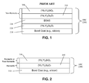
- FIG. 1 is an illustration of an example of a prior art EBC having non-hermetic rare earth silicate-based layers in combination with BSAS.
- the present disclosure provides a rare earth silicate-based hermetic layer.
- the rare earth silicate-based hermetic layer comprises a thermal sprayed coating comprising a rare earth silicate having a hermetic microstructure having a density of 85% or more of its theoretical density.
- the present disclosure provides an environmental barrier coating comprising: a bond coat layer comprising silicon; and at least one rare earth silicate-based hermetic layer deposited on the bond coat layer by thermal spraying.
- the rare earth silicate-based hermetic layer comprises a thermal sprayed coating comprising a rare earth silicate having a hermetic microstructure having a density of 85% or more of its theoretical density.
- the present disclosure provides an article having an environmental barrier coating, where the article comprises: a substrate comprising a ceramic matrix composite; and an environmental barrier coating deposited on a surface of the substrate.
- the environmental barrier coating of the article comprises: a bond coat layer comprising silicon; and at least one rare earth silicate-based hermetic layer deposited on the bond coat layer by thermal spraying, wherein said rare earth silicate-based hermetic layer comprises a thermal sprayed coating comprising a rare earth silicate having a hermetic microstructure having a density of 85% or more of its theoretical density.
- a non-hermetic layer is deposited between the bond coat layer and the at least one rare earth silicate-based hermetic layer of the environmental barrier coating of the article.
- a suitable non-hermetic layer for use in the environmental barrier coating of the article can include, without limitation, a non-hermetic layer comprising a rare earth silicate that can be, without limitation, (Yb x , Y 1-x ) 2 Si 2 O 7 where 0 ⁇ x ⁇ 1.
- the present disclosure provides a thermal spray feedstock for producing a rare earth silicate-based hermetic layer.
- the thermal spray feedstock comprises a suspension comprising a rare earth silicate and a sintering aid suspended in a liquid carrier, where the sintering aid comprises an oxide or a plurality of oxides, and where thermal spraying of the suspension is effective to yield a rare earth silicate-based hermetic layer comprising a rare earth silicate having a hermetic microstructure having a density of 85% or more of its theoretical density.
- the thermal spray feedstock further comprises a surfactant.
- the present disclosure provides a method for making a rare earth silicate-based hermetic layer.
- This method includes the following steps: providing a thermal spray feedstock according to the present disclosure; and subjecting the thermal spray feedstock to a thermal spraying process to produce a rare earth silicate-based hermetic layer comprising a rare earth silicate having a hermetic microstructure having a density of 85% or more of its theoretical density.
- the present disclosure provides a method for producing a substrate having an environmental barrier coating.
- This method includes the following steps: providing a substrate comprising a ceramic matrix composite; and applying an environmental barrier coating to the substrate.
- the environmental barrier coating includes: a bond coat layer comprising silicon; and at least one rare earth silicate-based hermetic layer deposited on the bond coat layer by thermal spraying.
- the rare earth silicate-based hermetic layer comprises a thermal sprayed coating comprising a rare earth silicate having a hermetic microstructure having a density of 85% or more of its theoretical density.
- a non-hermetic layer is deposited between the bond coat layer and the at least one rare earth silicate-based hermetic layer of the environmental barrier coating of the article.
- a suitable non-hermetic layer for use in the environmental barrier coating of the article can include, without limitation, a non-hermetic layer comprising a rare earth silicate that can be, without limitation, (Yb x , Y 1-x ) 2 Si 2 O 7 where 0 ⁇ x ⁇ 1.
- the present disclosure describes a chemical composition that allows an environmental barrier coating (EBC) to be thermally sprayed to a hermetic state.
- EBC environmental barrier coating
- the present disclosure provides for reducing the number of EBC layers necessary to protect a ceramic matrix composite (CMC), for example from five to three.
- CMC ceramic matrix composite
- the present disclosure involves the addition of iron oxide, aluminum oxide, or any other sintering aid for a rare earth (e.g., Yb, Y, Sc, Lu, etc.) silicate to the thermal spray feedstock material.
- a rare earth silicate e.g., Yb, Y, Sc, Lu, etc.
- These sintering aides reduce the sintering temperature of the rare earth silicate substantially, which allow the coating to sinter in-situ to a hermetic density (typically > 85% of the theoretical rare earth silicate density).
- sintering can also be carried out ex-situ.
- the present disclosure provides a means for lowering the sintering temperature of rare-earth silicate materials such as (Yb and/or Y) 2 Si 2 O 7 and (Yb and/or Y) 2 SiO 5 .
- rare-earth silicate materials such as (Yb and/or Y) 2 Si 2 O 7 and (Yb and/or Y) 2 SiO 5 .
- the present disclosure generally relates to a rare earth silicate-based hermetic layer, environmental barrier coatings comprising the rare earth silicate-based hermetic layer, articles having an environmental barrier coating as disclosed, thermal spray feedstocks for producing the rare earth silicate-based hermetic layer, methods of making the rare earth silicate-based hermetic layer, and methods of using the rare earth silicate-based hermetic layer.
- hermeticity is achieved after heat treatment of the thermal spray layer.
- heat treatment of the thermal spray layer can be conducted either in-situ or ex-situ.
- the present disclosure provides a rare earth silicate-based hermetic layer.
- the rare earth silicate-based hermetic layer comprises a thermal sprayed coating comprising a rare earth silicate having a hermetic microstructure having a density of 85% or more of its theoretical density.
- the rare earth silicate-based hermetic layer comprises a thermal sprayed coating comprising a rare earth silicate having a hermetic microstructure having a density of 90% or more of its theoretical density, 95% or more of its theoretical density, or 97% or more of its theoretical density.
- the hermetic microstructure of the rare earth silicate-based hermetic layer has a closed porosity.
- the closed porosity comprises a porosity by volume of less than about 15 percent.
- the closed porosity comprises a porosity by volume of less than about 10 percent, less than about 5 percent, or less than about 3 percent.
- the hermetic microstructure comprises a dense rare earth silicate phase and an optional glassy phase.
- the hermetic microstructure comprises a dense rare earth silicate phase and a glassy phase.
- the hermetic microstructure comprises a dense rare earth silicate phase without a glassy phase.
- the thermal sprayed coating has a thickness of between about 5 micrometers and about 1,200 micrometers. In various other embodiments, the thermal sprayed coating has a thickness range of between about 10-1,000 micrometers, 10-800 micrometers, 10-500 micrometers, 10-400 micrometers, 10-300 micrometers, 10-200 micrometers, 10-100 micrometers, 10-50 micrometers, and the like.
- the rare earth silicate according to the present disclosure comprises a rare earth element selected from the group consisting of ytterbium (Yb), yttrium (Y), scandium (Sc), lutetium (Lu), lanthanum (La), cerium (Ce), praseodymium (Pr), neodymium (Nd), samarium (Sm), dysprosium (Dy), holmium (Ho), erbium (Er), thulium (Tm), europium (Eu), gadolinium (Gd), terbium (Tb), promethium (Pm), and a mixture thereof.
- Yb ytterbium
- Y scandium
- Sc lutetium
- La lanthanum
- Ce cerium
- Pr praseodymium
- Nd neodymium
- Sm samarium
- Dy dysprosium
- Ho holmium
- Er erbium
- Tm
- the rare earth silicate can be (Yb x , Y 1-x ) 2 Si 2 O 7 where 0 ⁇ x ⁇ 1 or (Yb y -Y 1- y) 2 SiO 5 , where 0 ⁇ y ⁇ 1 or a mixture thereof.
- the rare earth silicate is (Yb 0.6 Y 0.4 ) 2 Si 2 O 7 .
- the rare earth silicate comprises from about 90 wt% to about 99.5 wt% of the thermal sprayed coating.
- the rare earth silicate-based hermetic layer comprises a first layer comprising a first rare earth silicate and a second layer comprising a second rare earth silicate, wherein the first rare earth silicate is (Yb x , Y 1-x ) 2 Si 2 O 7 where 0 ⁇ x ⁇ 1 and the second rare earth silicate is (Yb y -Y 1-y ) 2 SiO 5 , where 0 ⁇ y ⁇ 1.
- the first rare earth silicate is (Yb 0.6 Y 0.4 ) 2 Si 2 O 7 and the second rare earth silicate is Y 2 SiO 5 .
- the hermetic microstructure of the rare earth silicate can be formed by sintering the rare earth silicate in-situ with a sintering aid comprising an oxide or a plurality of oxides.
- suitable sintering aid can include, without limitation, metallic iron, Al 2 O 3 , Fe 3 O 4 , SiO 2 , Fe 2 O 3 , LiYO 2 , and the like.
- the plurality of sintering aid oxides comprises metallic iron, Al 2 O 3 , Fe 3 O 4 , and SiO 2 .
- the hermetic microstructure of the rare earth silicate can be formed by sintering the rare earth silicate ex-situ.
- the present disclosure provides an environmental barrier coating comprising: a bond coat layer comprising silicon; and at least one rare earth silicate-based hermetic layer deposited on the bond coat layer by thermal spraying.
- the rare earth silicate-based hermetic layer comprises a thermal sprayed coating comprising a rare earth silicate having a hermetic microstructure having a density of 85% or more of its theoretical density.
- the rare earth silicate-based hermetic layer comprises a thermal sprayed coating comprising a rare earth silicate having a hermetic microstructure having a density of 90% or more of its theoretical density, 95% or more of its theoretical density, or 97% or more of its theoretical density.
- the various embodiments of the rare earth silicate-based hermetic layer as disclosed herein also relate to the environmental barrier coating. Therefore, for example, the hermetic microstructure of the rare earth silicate-based hermetic layer of the environmental barrier coating comprises a closed porosity, where the closed porosity comprises a porosity by volume of less than about 15 percent. As provided herein, in various other embodiments, the closed porosity comprises a porosity by volume of less than about 10 percent, less than about 5 percent, or less than about 3 percent.
- the bond coat layer of the environmental barrier coating comprises a thickness of between about 1 micrometer and about 200 micrometers
- the at least one rare earth silicate-based hermetic layer comprises a thickness of between about 5 micrometers and about 1,200 micrometers.
- the bond coat layer can have a thickness ranging from about 1-150 micrometers, about 1-100 micrometers, about 1-75 micrometers, about 1-50 micrometers, about 1-25 micrometers, about 1-10 micrometers, and the like.
- the at least one rare earth silicate-based hermetic layer comprises a thickness range of between about 10-1,000 micrometers, 10-800 micrometers, 10-500 micrometers, 10-400 micrometers, 10-300 micrometers, 10-200 micrometers, 10-100 micrometers, 10-50 micrometers, and the like.
- the at least one rare earth silicate-based hermetic layer comprises a first layer comprising a first rare earth silicate and a second layer comprising a second rare earth silicate, with the first layer being deposited between the bond coat layer and the second layer.
- the first rare earth silicate is (Yb x , Y 1-x ) 2 Si 2 O 7 , where 0 ⁇ x ⁇ 1
- the second rare earth silicate is (Yb y -Y 1-y ) 2 SiO 5 , where 0 ⁇ y ⁇ 1.
- the first rare earth silicate is (Yb 0.6 Y 0.4 ) 2 Si 2 O 7 and the second rare earth silicate is Y 2 SiO 5 .
- a non-hermetic layer is deposited between the bond coat layer and the first layer.
- An example of a suitable non-hermetic layer for depositing between the bond coat layer and the first layer can include, without limitation, a non-hermetic layer comprising a rare earth silicate that can be, without limitation, (Yb x , Y 1-x ) 2 Si 2 O 7 where 0 ⁇ x ⁇ 1.
- FIG. 1 is a schematic cross sectional view of a prior art EBC having non-hermetic rare earth silicate-based layers.
- EBC 200 includes bond coat 210 (e.g., silicon), (Yb,Y) 2 Si 2 O 7 layer 220, BSAS layer 230, (Yb,Y) 2 Si 2 O 7 layer 240, and (Yb,Y) 2 SiO 5 layer 250.
- BSAS layer 230 provides a glassy hermetic layer.
- (Yb,Y) 2 Si 2 O 7 layer 220 must be inserted between silicon bond coat 210 and BSAS layer 230.
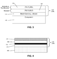
- EBC 300 of the present disclosure includes a bond coat 310 (e.g., silicon) having a hermetic (Yb,Y) 2 Si 2 O 7 layer 340 and a (Yb,Y) 2 SiO 5 layer 350 layered onto bond coat 310.
- bond coat 310 e.g., silicon
- (Yb,Y) 2 SiO 5 layer 350 may be either hermetic or non-hermetic.
- the present disclosure provides an article having an environmental barrier coating, where the article comprises: a substrate comprising a ceramic matrix composite; and an environmental barrier coating deposited on a surface of the substrate.
- the environmental barrier coating of the article comprises: a bond coat layer comprising silicon; and at least one rare earth silicate-based hermetic layer deposited on the bond coat layer by thermal spraying, where the rare earth silicate-based hermetic layer comprises a thermal sprayed coating comprising a rare earth silicate having a hermetic microstructure having a density of 85% or more of its theoretical density.
- the rare earth silicate-based hermetic layer comprises a thermal sprayed coating comprising a rare earth silicate having a hermetic microstructure having a density of 90% or more of its theoretical density, 95% or more of its theoretical density, or 97% or more of its theoretical density.
- a non-hermetic layer is deposited between the bond coat layer and the at least one rare earth silicate-based hermetic layer of the environmental barrier coating of the article.
- a suitable non-hermetic layer for use in the environmental barrier coating of the article can include, without limitation, a non-hermetic layer comprising a rare earth silicate that can be, without limitation, (Yb x , Y 1-x ) 2 Si 2 O 7 where 0 ⁇ x ⁇ 1.
- component 400 includes an environmental barrier coating 300 that comprises a bond coat 310 (e.g., silicon) having a rare earth silicate-based hermetic layer that comprises a hermetic (Yb,Y) 2 Si 2 O 7 layer 340 and a (Yb,Y) 2 SiO 5 layer 350 layered onto bond coat 310.
- bond coat 310 e.g., silicon
- Yb,Y hermetic
- (Yb,Y) 2 SiO 5 layer 350 may be either hermetic or non-hermetic.
- component 400 includes an environmental barrier coating 300 that comprises a bond coat 310 (e.g., silicon) having a rare earth silicate-based hermetic layer that comprises a hermetic (Yb,Y) 2 Si 2 O 7 layer 340 and a (Yb,Y) 2 SiO 5 layer 350 layered onto bond coat 310, and further with an optional non-hermetic layer 320 between bond coat 310 and hermetic (Yb,Y) 2 Si 2 O 7 layer 340.
- bond coat 310 e.g., silicon
- Yb,Y) 2 SiO 5 layer 350 layered onto bond coat 310, and further with an optional non-hermetic layer 320 between bond coat 310 and hermetic (Yb,Y) 2 Si 2 O 7 layer 340.
- (Yb,Y) 2 SiO 5 layer 350 may be either hermetic or non-hermetic.
- An example of a suitable optional non-hermetic layer 320 can include, without limitation, a non-hermetic layer comprising a rare earth silicate that can be, without limitation, (Yb x ,Y 1-x ) 2 Si 2 O 7 where 0 ⁇ x ⁇ 1.
- the articles of the present disclosure can include, without limitation, a turbine engine component selected from the group consisting of a combustor component, turbine blades, shrouds, nozzles, heat shields, and vanes.
- a turbine engine component selected from the group consisting of a combustor component, turbine blades, shrouds, nozzles, heat shields, and vanes.
- the present disclosure provides a thermal spray feedstock for producing a rare earth silicate-based hermetic layer.
- the thermal spray feedstock comprises a suspension comprising a rare earth silicate and a sintering aid suspended in a liquid carrier, where the sintering aid comprises an oxide or a plurality of oxides, and where thermal spraying of the suspension is effective to yield a rare earth silicate-based hermetic layer comprising a rare earth silicate having a hermetic microstructure having a density of 85% or more of its theoretical density.
- the rare earth silicate-based hermetic layer comprises a rare earth silicate having a hermetic microstructure having a density of 90% or more of its theoretical density, 95% or more of its theoretical density, or 97% or more of its theoretical density.
- suitable rare earth silicates for use in the rare earth silicate-based hermetic layer produced by the thermal spray feedstock can include, without limitation, a rare earth element selected from the group consisting of ytterbium (Yb), yttrium (Y), scandium (Sc), lutetium (Lu), lanthanum (La), cerium (Ce), praseodymium (Pr), neodymium (Nd), samarium (Sm), dysprosium (Dy), holmium (Ho), erbium (Er), thulium (Tm), europium (Eu), gadolinium (Gd), terbium (Tb), promethium (Pm), and a mixture thereof.
- a rare earth element selected from the group consisting of ytterbium (Yb), yttrium (Y), scandium (Sc), lutetium (Lu), lanthanum (La), cerium (Ce), praseodymium (Pr
- the rare earth silicate is (Yb x , Y 1-x ) 2 Si 2 O 7 where 0 ⁇ x ⁇ 1 or (Yb y -Y 1-y ) 2 SiO 5 where 0 ⁇ y ⁇ 1 or mixtures thereof.
- the rare earth silicate is (Yb 0.6 Y 0.4 ) 2 Si 2 O 7 .
- the suspension comprises from about 1 wt% to about 40 wt% of the rare earth silicate. In other embodiments of the thermal spray feedstock, the suspension comprises from about 3 wt% to about 30 wt% of the rare earth silicate. In other embodiments of the thermal spray feedstock, the suspension comprises from about 5 wt% to about 20 wt% of the rare earth silicate.
- the rare earth silicate is in a form of a particle having an outside diameter of between about 0.01 micrometers and about 15 micrometers. In other embodiments of the thermal spray feedstock, the rare earth silicate is in a form of a particle having an outside diameter of between about 0.1 micrometers and about 10 micrometers. In other embodiments of the thermal spray feedstock, the rare earth silicate is in a form of a particle having an outside diameter of between about 0.4 micrometers and about 8 micrometers.
- the suspension comprises less than about 5 wt% of the sintering aid.
- the sintering aid is selected from the group consisting of metallic iron, Al 2 O 3 , Fe 3 O 4 , SiO 2 , and Fe 2 O 3 .
- a suspension comprising the plurality of sintering aid oxides comprises from about 0 wt% to about 0.5 wt% of Al 2 O 3 , from about 0.5 wt% to about 2 wt% of Fe 3 O 4 , and from about 0 wt% to about 2 wt% of SiO 2 .
- the sintering aid oxide is in a form of a fine particle having an outside diameter of between about 5 nanometers and about 3 micrometers, between about 5 nanometers and about 100 nanometers, between about 30 nanometers and about 70 nanometers.
- the sintering aids are nanopowders and the rare earth silicates are micron-sized.
- the thermal spray feedstock comprises a liquid carrier.
- suitable liquid carriers can include, without limitation, alcohols, water, and mixtures thereof.
- the liquid carrier is an alcohol, and more specifically ethanol, although any other alcohols can be used.
- Other liquids can be used as the liquid carrier and generally evaporate in the process. While water and alcohols are the more common liquid carriers, the present disclosure covers the use of any suitable liquid carrier for the thermal spray feedstock.
- the thermal spray feedstock can further comprise a surfactant.
- Suitable surfactants can include, without limitation, polytheyleneimine, polyvinylpyrrolidone, salts of polymethacrylate, and other dispersants common to ceramic processing.
- the present disclosure provides a method for making a rare earth silicate-based hermetic layer.
- This method includes the following steps: providing a thermal spray feedstock according to the present disclosure; and subjecting the thermal spray feedstock to a thermal spraying process to produce a rare earth silicate-based hermetic layer comprising a rare earth silicate having a hermetic microstructure having a density of 85% or more of its theoretical density.
- the rare earth silicate-based hermetic layer comprises a rare earth silicate having a hermetic microstructure having a density of 90% or more of its theoretical density, 95% or more of its theoretical density, or 97% or more of its theoretical density.
- the present disclosure provides a method for producing a substrate having an environmental barrier coating.
- This method includes the following steps: providing a substrate comprising a ceramic matrix composite; and applying an environmental barrier coating to the substrate.
- the environmental barrier coating includes: a bond coat layer comprising silicon; and at least one rare earth silicate-based hermetic layer deposited on the bond coat layer by thermal spraying.
- the rare earth silicate-based hermetic layer comprises a thermal sprayed coating comprising a rare earth silicate having a hermetic microstructure having a density of 85% or more of its theoretical density.
- the rare earth silicate-based hermetic layer comprises a rare earth silicate having a hermetic microstructure having a density of 90% or more of its theoretical density, 95% or more of its theoretical density, or 97% or more of its theoretical density.
- the present disclosure describes a chemical composition that allows an environmental barrier coating (EBC) to be thermally sprayed to a hermetic state.
- EBC environmental barrier coating
- the present disclosure provides for reducing the number of EBC layers necessary to protect a ceramic matrix composite (CMC), for example from five to three.
- CMC ceramic matrix composite
- the present disclosure involves the addition of iron oxide, aluminum oxide, or any other sintering aid for a rare earth (e.g., Yb, Y, Sc, Lu, etc.) silicate to the thermal spray powder feed.
- a rare earth silicate e.g., Yb, Y, Sc, Lu, etc.
- sintering aides reduce the sintering temperature of the rare earth silicate substantially, which allow the coating to sinter in-situ to a hermetic density (typically > 85% of the theoretical rare earth silicate density).
- sintering can also be carried out ex-situ.
- the present disclosure provides a means for lowering the sintering temperature of rare-earth silicate materials such as (Yb and/or Y) 2 Si 2 O 7 and (Yb and/or Y) 2 SiO 5 .
- rare-earth silicate materials such as (Yb and/or Y) 2 Si 2 O 7 and (Yb and/or Y) 2 SiO 5 .
- sintering can be accomplished by heating a dried component at a rate of from about 1° C./min to about 15° C./min to a temperature of from about 1100° C. to about 1700° C. and holding the component at that temperature for from about 0 to about 24 hours. In other embodiments, sintering can be accomplished by heating the coated component at a rate of from about 5° C./min to about 15° C./min to a temperature of from about 1300° C. to about 1375° C. and holding the component at that temperature for from about 0 to about 24 hours.
- the bond coat layer may be applied by thermal spray processes, chemical vapor deposition processes, electron beam physical vapor deposition processes, dipping in molten silicon, sputtering processes, and other conventional application processes known to those skilled in the art.
- a liquid feedstock is fed to a thermal spray process.
- the liquid feedstock comprises: a liquid carrier (Ethanol); suspended (Yb,Y) 2 Si 2 O 7 particles; a surfactant (PEI); sintering aids (Al 2 O 3 , Fe 3 O 4 and SiO 2 ); and sintering aids are added to the suspension in the form of fine particles.
- the liquid feedstock is fed in the process using a peristaltic pump which carries it from a stirred vessel to the thermal spray process.
- the thermal spray process is either a plasma spray torch or a High Velocity Oxi-Fuel torch (HVOF).
- the thermal spray process parameters are adjusted so that upon interaction with the thermal spray process, the suspended particles are liberated from the liquid carrier, heated and accelerated toward a substrate. Further, the at least partially molten particles are deposited onto the substrate surface to form a coating.
- the main process parameters are gun power and stand-off distance between the torch and the substrate to be coated.
- the main process parameters are gas flow rates and composition, and stand-off distance between the torch and the substrate to be coated.
- FIG. 5 shows one embodiment of the constituents of the final coating.
- the resulting coating is hermetic and is composed of: dense (Yb,Y) 2 Si 2 O 7 phase; closed porosity; glassy phase; and other phase (e.g., maybe from from Yb, Y, Si, Al, Fe, O and mixtures thereof).
- One exemplary method for making a feedstock is set forth as follows: Starting powder: (Yb,Y) 2 Si 2 O 7 from St-Gobain (DV1099 - fines). Starting powder wet milled to size in denatured ethanol (Fisher A-407). Milled slurry diluted with denatured ethanol to achieve desired concentration. Addition of surfactant (PEI from Alfa Aesar) to stabilize suspension. Add ⁇ 0.07% PEI. Mix sintering aids in suspension: 1mol% Al 2 O 3 , from Alfa Aesar #44931; 2mol% Fe 3 O 4 from Sigma Aldrich #637106; and 1wt% SiO 2 , from Sigma Aldrich #381276. Sample feedstock materials are set forth in Table 1.
- Table 1 The solid concentration and particle size distribution of the (Yb,Y) 2 Si 2 O 7 particles in the sample feedstock materials are listed in Table 1.
- Table 1 Feedstock Material Feedstock ID Wt% D 50 ( ⁇ m) D 10 ( ⁇ m) D 90 ( ⁇ m) 1-A 10 0.98 0.55 2.00 1-B 5 0.99 0.51 2.48 2-A 20 1.97 0.65 5.05 2-B 5 2.09 0.66 5.04 2-C 10 1.85 0.63 4.46 2-D 10 1.96 0.65 5.00 NSI* 5 1.95 0.64 4.72 3-A 10 2.88 0.73 7.32 3-B 10 3.37 0.78 7.75 *This suspension does not have any sintering aids mixed in suspension.
- Exemplary spray conditions for use in the present disclosure are provided below and set forth in Table 2 and Table 3.
- Various materials and methods include the following: Plasma gun: Axial III from Northwest Mettech Corp., Vancouver, Canada; HVOF gun: GTV-770.000-AUS, Genie Products, Brevard, NC, USA; and Peristaltic feed pump: Watson Marlow, 520 Series EA, Model 520SN/REH.
- Table 2 Plasma Spray Conditions Spray condition ID Feedstock ID Power (kW) Stand-Off Distance (cm) P-1 1-B 51 7.6 P-2 2-B 79 6.4 P-3 3-A 78 6.4 P-4 2-D 79 6.4 Table 3: HVOF Spray Conditions Spray Condition ID Feedstock ID H2 flow Scfh (140 psi) O2 flow Scfh (170 psi) Air cap flow scfh (100 psi) Stand-off Distance (cm) H-1 1-A 65 35 28 10.2 H-2 2-A 65 35 28 12.7 H-3 3-B 65 35 28 12.7 H-4 2-C 65 35 28 12.7 H-5 NSI 65 35 28 12.7
- Exemplary heat treatment conditions for use in the present disclosure are provided below and set forth in Table 4. Samples were treated in an air furnace. Table 4: Plasma Spray Conditions Heat-treatment ID Starting temperature (°C) Final temperature (°C) Ramp rate (°C/min) Hold time at temperature (hours) Cooling HT-1 20 1344 5 10 Furnace cool HT-2 20 1315 5 10 Furnace cool HT-3 20 1315 5 50 Furnace cool
- Exemplary steam testing for hermeticity examples are provided below.
- a 2-hour cycle was conducted as follows: Start at room temperature ( ⁇ 20°C); Lower sample in hot zone (1315°C); Soak at 1315°C for -106 minutes; Raise sample out of hot zone (room temperature); and Soak at room temperature for 10 minutes (in the furnace, samples are at 1315°C; samples cool down to less than 100°C when they are soaked at room temperature for 10 minutes).
- Characterization Thickness of thermally grown oxide (TGO) layer on Si bond coat.
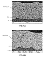
- FIG. 6A Sample H2-1344)
- FIG. 6B Sample H4-1315-50
- FIG. 6C Sample P2-1344
- FIG. 7A examples of non-hermetic coatings
- FIG. 7B examples of non-hermetic coatings
Landscapes
- Chemical & Material Sciences (AREA)
- Engineering & Computer Science (AREA)
- Materials Engineering (AREA)
- Organic Chemistry (AREA)
- Ceramic Engineering (AREA)
- Plasma & Fusion (AREA)
- Physics & Mathematics (AREA)
- Mechanical Engineering (AREA)
- Chemical Kinetics & Catalysis (AREA)
- Metallurgy (AREA)
- Structural Engineering (AREA)
- General Engineering & Computer Science (AREA)
- Inorganic Chemistry (AREA)
- Coating By Spraying Or Casting (AREA)
- Turbine Rotor Nozzle Sealing (AREA)
- Manufacturing & Machinery (AREA)
Abstract
Description
- Embodiments described herein generally relate to compositions for making environmental barrier coatings and environmental barrier coatings comprising the same. More particularly, embodiments described herein generally relate to environmental barrier coatings that include at least one rare earth silicate-based hermetic layer. Other embodiments are made and densified using at least one sintering aid.
- Higher operating temperatures for gas turbine engines are continuously being sought in order to improve their efficiency. However, as operating temperatures increase, the high temperature durability of the components of the engine must correspondingly increase. Significant advances in high temperature capabilities have been achieved through the formulation of iron, nickel, and cobalt-based superalloys. While superalloys have found wide use for components used throughout gas turbine engines, and especially in the higher temperature sections, alternative lighter-weight component materials have been proposed.
- Ceramic matrix composites (CMCs) are a class of materials that consist of a reinforcing material surrounded by a ceramic matrix phase. Such materials, along with certain monolithic ceramics (i.e. ceramic materials without a reinforcing material), are currently being used for higher temperature applications. These ceramic materials are lightweight compared to superalloys, yet can still provide strength and durability to the component made therefrom. Therefore, such materials are currently being considered for many gas turbine components used in higher temperature sections of gas turbine engines, such as airfoils (e.g. turbines, and vanes), combustors, shrouds and other like components, that would benefit from the lighter-weight and higher temperature capability these materials can offer.
- CMC and monolithic ceramic components can be coated with environmental barrier coatings (EBCs) to protect them from the harsh environment of high temperature engine sections. EBCs can provide a dense, hermetic seal against the corrosive gases in the hot combustion environment, which can rapidly oxidize silicon-containing CMCs and monolithic ceramics. Additionally, silicon oxide is not stable in high temperature steam, but is converted to volatile (gaseous) silicon hydroxide species. Thus, EBCs can help prevent dimensional changes in the ceramic component due to such oxidation and volatilization processes. Unfortunately, there can be some undesirable issues associated with standard, industrial coating processes such as plasma spray and vapor deposition (i.e. chemical vapor deposition, CVD, and electron beam physical vapor deposition, EBPVD) currently used to apply EBCs.
- A typical air plasma spray (APS) microstructure for a rare earth disilicate is porous in the deposited state and is not hermetic toward the gaseous species that cause volatilization of the ceramic matrix composite. Therefore, a glassy layer such as barium strontium alumino-silicate (BSAS) is sprayed to provide a hermetic layer toward these gaseous species. However, this glassy layer cannot contact a silicon source such as silicon or silica and thus an additional layer of rare earth silicate must be sprayed to separate the glassy layer from the silica source.
FIG. 1 is an illustration of an example of a prior art EBC having non-hermetic rare earth silicate-based layers in combination with BSAS. - Accordingly, there remains a need for environmental barrier coatings to protect CMCs from the high temperature steam environments present in gas turbine engines.
- The present system and techniques are directed to overcoming these and other deficiencies in the art.
- According to one aspect, the present disclosure provides a rare earth silicate-based hermetic layer. The rare earth silicate-based hermetic layer comprises a thermal sprayed coating comprising a rare earth silicate having a hermetic microstructure having a density of 85% or more of its theoretical density.
- According to another aspect, the present disclosure provides an environmental barrier coating comprising: a bond coat layer comprising silicon; and at least one rare earth silicate-based hermetic layer deposited on the bond coat layer by thermal spraying. The rare earth silicate-based hermetic layer comprises a thermal sprayed coating comprising a rare earth silicate having a hermetic microstructure having a density of 85% or more of its theoretical density.
- According to another aspect, the present disclosure provides an article having an environmental barrier coating, where the article comprises: a substrate comprising a ceramic matrix composite; and an environmental barrier coating deposited on a surface of the substrate. The environmental barrier coating of the article comprises: a bond coat layer comprising silicon; and at least one rare earth silicate-based hermetic layer deposited on the bond coat layer by thermal spraying, wherein said rare earth silicate-based hermetic layer comprises a thermal sprayed coating comprising a rare earth silicate having a hermetic microstructure having a density of 85% or more of its theoretical density. In certain embodiments, a non-hermetic layer is deposited between the bond coat layer and the at least one rare earth silicate-based hermetic layer of the environmental barrier coating of the article. An example of a suitable non-hermetic layer for use in the environmental barrier coating of the article can include, without limitation, a non-hermetic layer comprising a rare earth silicate that can be, without limitation, (Ybx, Y1-x)2Si2O7 where 0 ≤ x ≤ 1.
- According to another aspect, the present disclosure provides a thermal spray feedstock for producing a rare earth silicate-based hermetic layer. The thermal spray feedstock comprises a suspension comprising a rare earth silicate and a sintering aid suspended in a liquid carrier, where the sintering aid comprises an oxide or a plurality of oxides, and where thermal spraying of the suspension is effective to yield a rare earth silicate-based hermetic layer comprising a rare earth silicate having a hermetic microstructure having a density of 85% or more of its theoretical density. In one embodiment, the thermal spray feedstock further comprises a surfactant.
- According to another aspect, the present disclosure provides a method for making a rare earth silicate-based hermetic layer. This method includes the following steps: providing a thermal spray feedstock according to the present disclosure; and subjecting the thermal spray feedstock to a thermal spraying process to produce a rare earth silicate-based hermetic layer comprising a rare earth silicate having a hermetic microstructure having a density of 85% or more of its theoretical density.
- According to another aspect, the present disclosure provides a method for producing a substrate having an environmental barrier coating. This method includes the following steps: providing a substrate comprising a ceramic matrix composite; and applying an environmental barrier coating to the substrate. The environmental barrier coating includes: a bond coat layer comprising silicon; and at least one rare earth silicate-based hermetic layer deposited on the bond coat layer by thermal spraying. The rare earth silicate-based hermetic layer comprises a thermal sprayed coating comprising a rare earth silicate having a hermetic microstructure having a density of 85% or more of its theoretical density. In certain embodiments of this method, a non-hermetic layer is deposited between the bond coat layer and the at least one rare earth silicate-based hermetic layer of the environmental barrier coating of the article. An example of a suitable non-hermetic layer for use in the environmental barrier coating of the article can include, without limitation, a non-hermetic layer comprising a rare earth silicate that can be, without limitation, (Ybx, Y1-x)2Si2O7 where 0 ≤ x ≤ 1.
- As provided herein, the present disclosure describes a chemical composition that allows an environmental barrier coating (EBC) to be thermally sprayed to a hermetic state. The present disclosure provides for reducing the number of EBC layers necessary to protect a ceramic matrix composite (CMC), for example from five to three. In one embodiment, the present disclosure involves the addition of iron oxide, aluminum oxide, or any other sintering aid for a rare earth (e.g., Yb, Y, Sc, Lu, etc.) silicate to the thermal spray feedstock material. These sintering aides reduce the sintering temperature of the rare earth silicate substantially, which allow the coating to sinter in-situ to a hermetic density (typically > 85% of the theoretical rare earth silicate density). As provided herein, sintering can also be carried out ex-situ.
- As described herein, the present disclosure provides a means for lowering the sintering temperature of rare-earth silicate materials such as (Yb and/or Y)2Si2O7 and (Yb and/or Y)2SiO5. Thus, the thermal spray layer deposited with a sintering aid eliminates the need for the glassy layer and the separation layer.
- These and other objects, features, and advantages of the present methods, systems, and techniques will become apparent from the following detailed description of the various aspects of the present disclosure taken in conjunction with the accompanying drawings.
- While the specification concludes with claims particularly pointing out and distinctly claiming the invention, it is believed that the embodiments set forth herein will be better understood from the following description in conjunction with the accompanying figures, in which like reference numerals identify like elements.
-
FIG. 1 is a schematic cross sectional view of an environmental barrier coating in the prior art. As shown,environmental barrier coating 200 has bond coat 210 (e.g., silicon), non-hermetic (Yb,Y)2Si2O7 layer 220,BSAS layer 230, non-hermetic (Yb,Y)2Si2O7 layer 240, and non-hermetic (Yb,Y)2SiO5 layer 250. -
FIG. 2 is a schematic cross sectional view of one embodiment of an environmental barrier coating in accordance with the present disclosure. -
FIG. 3 is a schematic cross sectional view of one embodiment of an article having an environmental barrier coating in accordance with the present disclosure. -
FIG. 4 is a schematic cross sectional view of one embodiment of a component having an environmental barrier coating in accordance with the present disclosure. -
FIG. 5 is a micrograph of one embodiment of a thermal spray hermetic (Yb,Y)2Si2O7 layer in accordance with the present disclosure. -
FIGS. 6A-6C are micrographs of various embodiments of hermetic (Yb,Y)2Si2O7 layers in accordance with the present disclosure. The layers are shown after steam testing for hermeticity.FIG. 6A corresponds to Sample H2-1344.FIG. 6B corresponds to Sample H4-1315-50.FIG. 6C corresponds to Sample P2-1344. -
FIGS. 7A-7B are micrographs of various embodiments of non-hermetic (Yb,Y)2Si2O7 layers described in the present disclosure.FIG. 7A corresponds to Sample H5-1344 and was steam tested.FIG. 7B corresponds to Sample P3-1344 and was steam tested. - The present disclosure generally relates to a rare earth silicate-based hermetic layer, environmental barrier coatings comprising the rare earth silicate-based hermetic layer, articles having an environmental barrier coating as disclosed, thermal spray feedstocks for producing the rare earth silicate-based hermetic layer, methods of making the rare earth silicate-based hermetic layer, and methods of using the rare earth silicate-based hermetic layer. In general, hermeticity is achieved after heat treatment of the thermal spray layer. As used herein, heat treatment of the thermal spray layer can be conducted either in-situ or ex-situ.
- According to one aspect, the present disclosure provides a rare earth silicate-based hermetic layer. The rare earth silicate-based hermetic layer comprises a thermal sprayed coating comprising a rare earth silicate having a hermetic microstructure having a density of 85% or more of its theoretical density. In various other embodiments, the rare earth silicate-based hermetic layer comprises a thermal sprayed coating comprising a rare earth silicate having a hermetic microstructure having a density of 90% or more of its theoretical density, 95% or more of its theoretical density, or 97% or more of its theoretical density.
- As provided herein, in certain embodiments, the hermetic microstructure of the rare earth silicate-based hermetic layer has a closed porosity. In particular embodiments, the closed porosity comprises a porosity by volume of less than about 15 percent. In various other embodiments, the closed porosity comprises a porosity by volume of less than about 10 percent, less than about 5 percent, or less than about 3 percent. In certain embodiments, the hermetic microstructure comprises a dense rare earth silicate phase and an optional glassy phase. Thus, in one embodiment, the hermetic microstructure comprises a dense rare earth silicate phase and a glassy phase. In another embodiment, the hermetic microstructure comprises a dense rare earth silicate phase without a glassy phase.
- As provided herein, in certain embodiments, the thermal sprayed coating has a thickness of between about 5 micrometers and about 1,200 micrometers. In various other embodiments, the thermal sprayed coating has a thickness range of between about 10-1,000 micrometers, 10-800 micrometers, 10-500 micrometers, 10-400 micrometers, 10-300 micrometers, 10-200 micrometers, 10-100 micrometers, 10-50 micrometers, and the like.
- As provided herein, the rare earth silicate according to the present disclosure comprises a rare earth element selected from the group consisting of ytterbium (Yb), yttrium (Y), scandium (Sc), lutetium (Lu), lanthanum (La), cerium (Ce), praseodymium (Pr), neodymium (Nd), samarium (Sm), dysprosium (Dy), holmium (Ho), erbium (Er), thulium (Tm), europium (Eu), gadolinium (Gd), terbium (Tb), promethium (Pm), and a mixture thereof. In one embodiment, the rare earth silicate can be (Ybx, Y1-x)2Si2O7 where 0 ≤ x ≤ 1 or (Yby-Y1-y)2SiO5, where 0 ≤ y ≤ 1 or a mixture thereof. In a particular embodiment, the rare earth silicate is (Yb0.6Y0.4)2Si2O7. In various embodiments, the rare earth silicate comprises from about 90 wt% to about 99.5 wt% of the thermal sprayed coating.
- In one embodiment, the rare earth silicate-based hermetic layer comprises a first layer comprising a first rare earth silicate and a second layer comprising a second rare earth silicate, wherein the first rare earth silicate is (Ybx, Y1-x)2Si2O7 where 0 ≤ x ≤ 1 and the second rare earth silicate is (Yby-Y1-y)2SiO5, where 0 ≤ y ≤ 1. In a particular embodiment, the first rare earth silicate is (Yb0.6Y0.4)2Si2O7 and the second rare earth silicate is Y2SiO5.
- As provided herein, the hermetic microstructure of the rare earth silicate can be formed by sintering the rare earth silicate in-situ with a sintering aid comprising an oxide or a plurality of oxides. As used herein, suitable sintering aid can include, without limitation, metallic iron, Al2O3, Fe3O4, SiO2, Fe2O3, LiYO2, and the like. In particular embodiments, the plurality of sintering aid oxides comprises metallic iron, Al2O3, Fe3O4, and SiO2. In various embodiments, the hermetic microstructure of the rare earth silicate can be formed by sintering the rare earth silicate ex-situ.
- According to another aspect, the present disclosure provides an environmental barrier coating comprising: a bond coat layer comprising silicon; and at least one rare earth silicate-based hermetic layer deposited on the bond coat layer by thermal spraying. The rare earth silicate-based hermetic layer comprises a thermal sprayed coating comprising a rare earth silicate having a hermetic microstructure having a density of 85% or more of its theoretical density. As provided herein, in various other embodiments, the rare earth silicate-based hermetic layer comprises a thermal sprayed coating comprising a rare earth silicate having a hermetic microstructure having a density of 90% or more of its theoretical density, 95% or more of its theoretical density, or 97% or more of its theoretical density.
- The various embodiments of the rare earth silicate-based hermetic layer as disclosed herein also relate to the environmental barrier coating. Therefore, for example, the hermetic microstructure of the rare earth silicate-based hermetic layer of the environmental barrier coating comprises a closed porosity, where the closed porosity comprises a porosity by volume of less than about 15 percent. As provided herein, in various other embodiments, the closed porosity comprises a porosity by volume of less than about 10 percent, less than about 5 percent, or less than about 3 percent.
- As provided herein, in certain embodiments, the bond coat layer of the environmental barrier coating comprises a thickness of between about 1 micrometer and about 200 micrometers, and the at least one rare earth silicate-based hermetic layer comprises a thickness of between about 5 micrometers and about 1,200 micrometers. In various embodiments, the bond coat layer can have a thickness ranging from about 1-150 micrometers, about 1-100 micrometers, about 1-75 micrometers, about 1-50 micrometers, about 1-25 micrometers, about 1-10 micrometers, and the like. In various other embodiments, the at least one rare earth silicate-based hermetic layer comprises a thickness range of between about 10-1,000 micrometers, 10-800 micrometers, 10-500 micrometers, 10-400 micrometers, 10-300 micrometers, 10-200 micrometers, 10-100 micrometers, 10-50 micrometers, and the like.
- In one embodiment of the environmental barrier coating, the at least one rare earth silicate-based hermetic layer comprises a first layer comprising a first rare earth silicate and a second layer comprising a second rare earth silicate, with the first layer being deposited between the bond coat layer and the second layer. In one embodiment, the first rare earth silicate is (Ybx, Y1-x)2Si2O7, where 0 ≤ x ≤ 1 and the second rare earth silicate is (Yby-Y1-y)2SiO5, where 0 ≤ y ≤ 1. In a particular embodiment, the first rare earth silicate is (Yb0.6Y0.4)2Si2O7 and the second rare earth silicate is Y2SiO5. In certain embodiments, a non-hermetic layer is deposited between the bond coat layer and the first layer. An example of a suitable non-hermetic layer for depositing between the bond coat layer and the first layer can include, without limitation, a non-hermetic layer comprising a rare earth silicate that can be, without limitation, (Ybx, Y1-x)2Si2O7 where 0 ≤ x ≤ 1.
- As set forth herein above,
FIG. 1 is a schematic cross sectional view of a prior art EBC having non-hermetic rare earth silicate-based layers. As shown inFIG. 1 ,EBC 200 includes bond coat 210 (e.g., silicon), (Yb,Y)2Si2O7 layer 220,BSAS layer 230, (Yb,Y)2Si2O7 layer 240, and (Yb,Y)2SiO5 layer 250.BSAS layer 230 provides a glassy hermetic layer. However, becauseBSAS layer 230 cannot be allowed to come into contact withsilicon bond coat 210, (Yb,Y)2Si2O7 layer 220 must be inserted betweensilicon bond coat 210 andBSAS layer 230. Thus, the EBC shown inFIG. 1 requires additional layers that are not required by the EBC of the present disclosure. By way of contrast, as shown inFIG. 2 ,EBC 300 of the present disclosure includes a bond coat 310 (e.g., silicon) having a hermetic (Yb,Y)2Si2O7 layer 340 and a (Yb,Y)2SiO5 layer 350 layered ontobond coat 310. In various embodiments ofEBC 300 ofFIG. 2 , (Yb,Y)2SiO5 layer 350 may be either hermetic or non-hermetic. - According to another aspect, the present disclosure provides an article having an environmental barrier coating, where the article comprises: a substrate comprising a ceramic matrix composite; and an environmental barrier coating deposited on a surface of the substrate. The environmental barrier coating of the article comprises: a bond coat layer comprising silicon; and at least one rare earth silicate-based hermetic layer deposited on the bond coat layer by thermal spraying, where the rare earth silicate-based hermetic layer comprises a thermal sprayed coating comprising a rare earth silicate having a hermetic microstructure having a density of 85% or more of its theoretical density. As provided herein, in various other embodiments, the rare earth silicate-based hermetic layer comprises a thermal sprayed coating comprising a rare earth silicate having a hermetic microstructure having a density of 90% or more of its theoretical density, 95% or more of its theoretical density, or 97% or more of its theoretical density. In certain embodiments, a non-hermetic layer is deposited between the bond coat layer and the at least one rare earth silicate-based hermetic layer of the environmental barrier coating of the article. An example of a suitable non-hermetic layer for use in the environmental barrier coating of the article can include, without limitation, a non-hermetic layer comprising a rare earth silicate that can be, without limitation, (Ybx, Y1-x)2Si2O7 where 0 ≤ x ≤ 1.
- Referring to
FIG. 3 , there is shown a schematic cross sectional view of one embodiment of an article in accordance with the present disclosure. As shown,component 400 includes anenvironmental barrier coating 300 that comprises a bond coat 310 (e.g., silicon) having a rare earth silicate-based hermetic layer that comprises a hermetic (Yb,Y)2Si2O7 layer 340 and a (Yb,Y)2SiO5 layer 350 layered ontobond coat 310. In various embodiments ofEBC 300 ofFIG. 3 , (Yb,Y)2SiO5 layer 350 may be either hermetic or non-hermetic. - Referring to
FIG. 4 , there is shown a schematic cross sectional view of another embodiment of an article in accordance with the present disclosure. As shown,component 400 includes anenvironmental barrier coating 300 that comprises a bond coat 310 (e.g., silicon) having a rare earth silicate-based hermetic layer that comprises a hermetic (Yb,Y)2Si2O7 layer 340 and a (Yb,Y)2SiO5 layer 350 layered ontobond coat 310, and further with an optionalnon-hermetic layer 320 betweenbond coat 310 and hermetic (Yb,Y)2Si2O7 layer 340. In various embodiments ofEBC 300 ofFIG. 4 , (Yb,Y)2SiO5 layer 350 may be either hermetic or non-hermetic. An example of a suitable optionalnon-hermetic layer 320 can include, without limitation, a non-hermetic layer comprising a rare earth silicate that can be, without limitation, (Ybx,Y1-x)2Si2O7 where 0 ≤ x ≤ 1. - Various articles can include the environmental barrier coating of the present disclosure. For example, in various embodiments, the articles of the present disclosure can include, without limitation, a turbine engine component selected from the group consisting of a combustor component, turbine blades, shrouds, nozzles, heat shields, and vanes.
- According to another aspect, the present disclosure provides a thermal spray feedstock for producing a rare earth silicate-based hermetic layer. The thermal spray feedstock comprises a suspension comprising a rare earth silicate and a sintering aid suspended in a liquid carrier, where the sintering aid comprises an oxide or a plurality of oxides, and where thermal spraying of the suspension is effective to yield a rare earth silicate-based hermetic layer comprising a rare earth silicate having a hermetic microstructure having a density of 85% or more of its theoretical density. As provided herein, in various other embodiments, the rare earth silicate-based hermetic layer comprises a rare earth silicate having a hermetic microstructure having a density of 90% or more of its theoretical density, 95% or more of its theoretical density, or 97% or more of its theoretical density.
- The various characteristics and embodiments of the rare earth silicate-based hermetic layer as disclosed herein also relate to the thermal spray feedstock for producing a rare earth silicate-based hermetic layer. For example, suitable rare earth silicates for use in the rare earth silicate-based hermetic layer produced by the thermal spray feedstock can include, without limitation, a rare earth element selected from the group consisting of ytterbium (Yb), yttrium (Y), scandium (Sc), lutetium (Lu), lanthanum (La), cerium (Ce), praseodymium (Pr), neodymium (Nd), samarium (Sm), dysprosium (Dy), holmium (Ho), erbium (Er), thulium (Tm), europium (Eu), gadolinium (Gd), terbium (Tb), promethium (Pm), and a mixture thereof. In various embodiments, the rare earth silicate is (Ybx, Y1-x)2Si2O7 where 0 ≤ x ≤ 1 or (Yby-Y1-y)2SiO5 where 0 ≤ y ≤ 1 or mixtures thereof. In a particular embodiment, the rare earth silicate is (Yb0.6Y0.4)2Si2O7.
- In certain embodiments of the thermal spray feedstock, the suspension comprises from about 1 wt% to about 40 wt% of the rare earth silicate. In other embodiments of the thermal spray feedstock, the suspension comprises from about 3 wt% to about 30 wt% of the rare earth silicate. In other embodiments of the thermal spray feedstock, the suspension comprises from about 5 wt% to about 20 wt% of the rare earth silicate.
- In certain embodiments of the thermal spray feedstock, the rare earth silicate is in a form of a particle having an outside diameter of between about 0.01 micrometers and about 15 micrometers. In other embodiments of the thermal spray feedstock, the rare earth silicate is in a form of a particle having an outside diameter of between about 0.1 micrometers and about 10 micrometers. In other embodiments of the thermal spray feedstock, the rare earth silicate is in a form of a particle having an outside diameter of between about 0.4 micrometers and about 8 micrometers.
- In certain embodiments of the thermal spray feedstock, the suspension comprises less than about 5 wt% of the sintering aid.
- In certain embodiments of the thermal spray feedstock, the sintering aid is selected from the group consisting of metallic iron, Al2O3, Fe3O4, SiO2, and Fe2O3. In certain embodiments, a suspension comprising the plurality of sintering aid oxides comprises from about 0 wt% to about 0.5 wt% of Al2O3, from about 0.5 wt% to about 2 wt% of Fe3O4, and from about 0 wt% to about 2 wt% of SiO2.
- In certain embodiments, the sintering aid oxide is in a form of a fine particle having an outside diameter of between about 5 nanometers and about 3 micrometers, between about 5 nanometers and about 100 nanometers, between about 30 nanometers and about 70 nanometers. In particular embodiments, the sintering aids are nanopowders and the rare earth silicates are micron-sized.
- In certain embodiments the thermal spray feedstock comprises a liquid carrier. Suitable liquid carriers can include, without limitation, alcohols, water, and mixtures thereof. In a particular embodiment, the liquid carrier is an alcohol, and more specifically ethanol, although any other alcohols can be used. Other liquids can be used as the liquid carrier and generally evaporate in the process. While water and alcohols are the more common liquid carriers, the present disclosure covers the use of any suitable liquid carrier for the thermal spray feedstock.
- In certain embodiments, the thermal spray feedstock can further comprise a surfactant. Suitable surfactants can include, without limitation, polytheyleneimine, polyvinylpyrrolidone, salts of polymethacrylate, and other dispersants common to ceramic processing.
- According to another aspect, the present disclosure provides a method for making a rare earth silicate-based hermetic layer. This method includes the following steps: providing a thermal spray feedstock according to the present disclosure; and subjecting the thermal spray feedstock to a thermal spraying process to produce a rare earth silicate-based hermetic layer comprising a rare earth silicate having a hermetic microstructure having a density of 85% or more of its theoretical density. As provided herein, in various other embodiments, the rare earth silicate-based hermetic layer comprises a rare earth silicate having a hermetic microstructure having a density of 90% or more of its theoretical density, 95% or more of its theoretical density, or 97% or more of its theoretical density.
- According to another aspect, the present disclosure provides a method for producing a substrate having an environmental barrier coating. This method includes the following steps: providing a substrate comprising a ceramic matrix composite; and applying an environmental barrier coating to the substrate. The environmental barrier coating includes: a bond coat layer comprising silicon; and at least one rare earth silicate-based hermetic layer deposited on the bond coat layer by thermal spraying. The rare earth silicate-based hermetic layer comprises a thermal sprayed coating comprising a rare earth silicate having a hermetic microstructure having a density of 85% or more of its theoretical density. As provided herein, in various other embodiments, the rare earth silicate-based hermetic layer comprises a rare earth silicate having a hermetic microstructure having a density of 90% or more of its theoretical density, 95% or more of its theoretical density, or 97% or more of its theoretical density.
- As provided herein, the present disclosure describes a chemical composition that allows an environmental barrier coating (EBC) to be thermally sprayed to a hermetic state. The present disclosure provides for reducing the number of EBC layers necessary to protect a ceramic matrix composite (CMC), for example from five to three. In one embodiment, the present disclosure involves the addition of iron oxide, aluminum oxide, or any other sintering aid for a rare earth (e.g., Yb, Y, Sc, Lu, etc.) silicate to the thermal spray powder feed. These sintering aides reduce the sintering temperature of the rare earth silicate substantially, which allow the coating to sinter in-situ to a hermetic density (typically > 85% of the theoretical rare earth silicate density). As provided herein, sintering can also be carried out ex-situ.
- As described herein, the present disclosure provides a means for lowering the sintering temperature of rare-earth silicate materials such as (Yb and/or Y)2Si2O7 and (Yb and/or Y)2SiO5. Thus, the thermal spray layer deposited with a sintering aid eliminates the need for the glassy layer and the separation layer.
- In various embodiments, sintering can be accomplished by heating a dried component at a rate of from about 1° C./min to about 15° C./min to a temperature of from about 1100° C. to about 1700° C. and holding the component at that temperature for from about 0 to about 24 hours. In other embodiments, sintering can be accomplished by heating the coated component at a rate of from about 5° C./min to about 15° C./min to a temperature of from about 1300° C. to about 1375° C. and holding the component at that temperature for from about 0 to about 24 hours.
- In accordance with aspects of the present disclosure, the bond coat layer may be applied by thermal spray processes, chemical vapor deposition processes, electron beam physical vapor deposition processes, dipping in molten silicon, sputtering processes, and other conventional application processes known to those skilled in the art.
- The following examples are intended to illustrate particular embodiments, but are by no means intended to limit the scope of the present systems and techniques.
- Suspension Thermal Spray for Hermetic (Yb,Y)2Si2O7 Layer
- One exemplary method for making a suspension thermal spray for hermetic (Yb,Y)2Si2O7 layer is set forth below.
- A liquid feedstock is fed to a thermal spray process. The liquid feedstock comprises: a liquid carrier (Ethanol); suspended (Yb,Y)2Si2O7 particles; a surfactant (PEI); sintering aids (Al2O3, Fe3O4 and SiO2); and sintering aids are added to the suspension in the form of fine particles. The liquid feedstock is fed in the process using a peristaltic pump which carries it from a stirred vessel to the thermal spray process. The thermal spray process is either a plasma spray torch or a High Velocity Oxi-Fuel torch (HVOF).
- The thermal spray process parameters are adjusted so that upon interaction with the thermal spray process, the suspended particles are liberated from the liquid carrier, heated and accelerated toward a substrate. Further, the at least partially molten particles are deposited onto the substrate surface to form a coating. For plasma spray, the main process parameters are gun power and stand-off distance between the torch and the substrate to be coated. For HVOF, the main process parameters are gas flow rates and composition, and stand-off distance between the torch and the substrate to be coated.
- The coated substrate is heat-treated to sinter the microstructure.
FIG. 5 shows one embodiment of the constituents of the final coating. As shown inFIGS. 6A-6C , the resulting coating is hermetic and is composed of: dense (Yb,Y)2Si2O7 phase; closed porosity; glassy phase; and other phase (e.g., maybe from from Yb, Y, Si, Al, Fe, O and mixtures thereof). - One exemplary method for making a feedstock is set forth as follows: Starting powder: (Yb,Y)2Si2O7 from St-Gobain (DV1099 - fines). Starting powder wet milled to size in denatured ethanol (Fisher A-407). Milled slurry diluted with denatured ethanol to achieve desired concentration. Addition of surfactant (PEI from Alfa Aesar) to stabilize suspension. Add < 0.07% PEI. Mix sintering aids in suspension: 1mol% Al2O3, from Alfa Aesar #44931; 2mol% Fe3O4 from Sigma Aldrich #637106; and 1wt% SiO2, from Sigma Aldrich #381276. Sample feedstock materials are set forth in Table 1. The solid concentration and particle size distribution of the (Yb,Y)2Si2O7 particles in the sample feedstock materials are listed in Table 1.
Table 1: Feedstock Material Feedstock ID Wt% D50 (µm) D10 (µm) D90 (µm) 1- A 10 0.98 0.55 2.00 1-B 5 0.99 0.51 2.48 2-A 20 1.97 0.65 5.05 2-B 5 2.09 0.66 5.04 2- C 10 1.85 0.63 4.46 2- D 10 1.96 0.65 5.00 NSI* 5 1.95 0.64 4.72 3- A 10 2.88 0.73 7.32 3- B 10 3.37 0.78 7.75 *This suspension does not have any sintering aids mixed in suspension. - Exemplary spray conditions for use in the present disclosure are provided below and set forth in Table 2 and Table 3. Various materials and methods include the following: Plasma gun: Axial III from Northwest Mettech Corp., Vancouver, Canada; HVOF gun: GTV-770.000-AUS, Genie Products, Brevard, NC, USA; and Peristaltic feed pump: Watson Marlow, 520 Series EA, Model 520SN/REH.
Table 2: Plasma Spray Conditions Spray condition ID Feedstock ID Power (kW) Stand-Off Distance (cm) P-1 1-B 51 7.6 P-2 2-B 79 6.4 P-3 3-A 78 6.4 P-4 2-D 79 6.4 Table 3: HVOF Spray Conditions Spray Condition ID Feedstock ID H2 flow Scfh (140 psi) O2 flow Scfh (170 psi) Air cap flow scfh (100 psi) Stand-off Distance (cm) H-1 1-A 65 35 28 10.2 H-2 2-A 65 35 28 12.7 H-3 3-B 65 35 28 12.7 H-4 2-C 65 35 28 12.7 H-5 NSI 65 35 28 12.7 - Exemplary heat treatment conditions for use in the present disclosure are provided below and set forth in Table 4. Samples were treated in an air furnace.
Table 4: Plasma Spray Conditions Heat-treatment ID Starting temperature (°C) Final temperature (°C) Ramp rate (°C/min) Hold time at temperature (hours) Cooling HT-1 20 1344 5 10 Furnace cool HT-2 20 1315 5 10 Furnace cool HT-3 20 1315 5 50 Furnace cool - Exemplary steam testing for hermeticity examples are provided below. The samples included a (Yb,Y)2Si2O7 layer on an Si coated SiC button. Atmosphere: PH2O = 0.9 atmosphere; and PO2 = 0.1 atmosphere. 500 hours test and 250 cycles. A 2-hour cycle was conducted as follows: Start at room temperature (∼20°C); Lower sample in hot zone (1315°C); Soak at 1315°C for -106 minutes; Raise sample out of hot zone (room temperature); and Soak at room temperature for 10 minutes (in the furnace, samples are at 1315°C; samples cool down to less than 100°C when they are soaked at room temperature for 10 minutes). Characterization: Thickness of thermally grown oxide (TGO) layer on Si bond coat. Criteria for hermeticity: Hermetic layer when TGO ≤ ∼6 µm. Various conditions and aspects of the samples are provided in Table 5.
Table 5: Steam Tested Samples Sample ID Spray Condition ID Heat-Treatment ID TGO Thickness (std. deviation) (µm) Hermetic? P1-1344 P-1 HT-1 (1344°C, 10 hours) >20 No P2-1344 P-2 HT-1 (1344°C, 10 hours) 5.1 (2.2) Yes P3-1344 P-3 HT-1 (1344°C, 10 hours) 15.3 (6.0) No H1-1344 H-1 HT-1 (1344°C, 10 hours) >20 No H2-1344 H-2 HT-1 (1344°C, 10 hours) 4.4 (2.1) Yes H3-1344 H-3 HT-1 (1344°C, 10 hours) 4.7 (2.5) Yes P4-1315-10 P-4 HT-2 (1315°C, 10 hours) 17.0 (2.2) No H4-1315-10 H-4 HT-2 (1315°C, 10 hours) 16.7(8) No P4-1315-50 P-4 HT-3 (1315°C, 50 hours) 5.0(1.9) Yes H4-1315-50 H-4 HT-3 (1315°C, 50 hours) 6.1 (3.2) Yes H5-1344 H-5 HT-1 (1344°C, 10 hours) 6.8 (7.6) No - Examples of steam tested hermetic coatings are illustrated in
FIG. 6A (Sample H2-1344),FIG. 6B (Sample H4-1315-50), andFIG. 6C (Sample P2-1344). By way of comparison, examples of non-hermetic coatings are illustrated inFIG. 7A (Sample H5-1344), andFIG. 7B (Sample P3-1344), - Various aspects and embodiments of the present invention are defined by the following numbered clauses:
- 1. A rare earth silicate-based hermetic layer comprising:
- a thermal sprayed coating comprising a rare earth silicate having a hermetic microstructure having a density of 85% or more of its theoretical density.
- 2. The rare earth silicate-based hermetic layer according to clause 1, wherein the hermetic microstructure comprises a closed porosity, said closed porosity comprising a porosity by volume of less than about 15 percent.
- 3. The rare earth silicate-based hermetic layer according to clause 1 or clause 2, wherein the hermetic microstructure comprises a dense rare earth silicate phase and an optional glassy phase.
- 4. The rare earth silicate-based hermetic layer according to any preceding clause, wherein the thermal sprayed coating has a thickness of between about 5 micrometers and about 1,200 micrometers.
- 5. The rare earth silicate-based hermetic layer according to any preceding clause, wherein the rare earth silicate comprises a rare earth element selected from the group consisting of ytterbium (Yb), yttrium (Y), scandium (Sc), lutetium (Lu), lanthanum (La), cerium (Ce), praseodymium (Pr), neodymium (Nd), samarium (Sm), dysprosium (Dy), holmium (Ho), erbium (Er), thulium (Tm), europium (Eu), gadolinium (Gd), terbium (Tb), promethium (Pm), and a mixture thereof.
- 6. The rare earth silicate-based hermetic layer according to any preceding clause, wherein the rare earth silicate is selected from the group consisting of (Ybx, Y1-x)2Si2O7 where 0 ≤ x ≤ 1, (Yby-Y1-y)2SiO5, where 0 ≤ y ≤ 1 or a mixture thereof
- 7. The rare earth silicate-based hermetic layer according to any preceding clause wherein said rare earth silicate-based hermetic layer comprises a first layer comprising a first rare earth silicate and a second layer comprising a second rare earth silicate, wherein the first rare earth silicate is (Ybx, Y1-x)2Si2O7 where 0 ≤ x ≤ 1 and the second rare earth silicate is (Yby-Y1-y)2SiO5, where 0 ≤ y ≤ 1.
- 8. The rare earth silicate-based hermetic layer according to clause 7, wherein the first rare earth silicate is (Yb0.6Y0.4)2Si2O7 and the second rare earth silicate is Y2SiO5.
- 9. The rare earth silicate-based hermetic layer according to any preceding clause, wherein the rare earth silicate comprises from about 90 wt% to about 99.5 wt% of the thermal sprayed coating.
- 10. The rare earth silicate-based hermetic layer according to any preceding clause, wherein the hermetic microstructure of the rare earth silicate is formed by sintering the rare earth silicate in-situ or ex-situ with a sintering aid comprising an oxide or a plurality of oxides.
- 11. The rare earth silicate-based hermetic layer according to
clause 10, wherein the sintering aid is selected from the group consisting of metallic iron, Al2O3, Fe3O4, SiO2, Fe2O3, and LiYO2. - 12. The rare earth silicate-based hermetic layer according to
clause 10, wherein plurality of sintering aid oxides comprises metallic iron, Al2O3, Fe3O4, and SiO2. - 13. An environmental barrier coating comprising:
- a bond coat layer comprising silicon; and
- at least one rare earth silicate-based hermetic layer deposited on the bond coat layer by thermal spraying,
- wherein said rare earth silicate-based hermetic layer comprises a thermal sprayed coating comprising a rare earth silicate having a hermetic microstructure having a density of 85% or more of its theoretical density.
- 14. The environmental barrier coating according to clause 13, wherein the hermetic microstructure comprises a closed porosity, said closed porosity comprising a porosity by volume of less than about 15 percent.
- 15. The environmental barrier coating according to clause 13 or clause 14, wherein the bond coat layer comprises a thickness of between about 1 micrometer and about 200 micrometers, and the at least one rare earth silicate-based hermetic layer comprises a thickness of between about 5 micrometers and about 1,200 micrometers.
- 16. The environmental barrier coating according to any one of clauses 13 to 15, wherein said at least one rare earth silicate-based hermetic layer comprises a first layer comprising a first rare earth silicate and a second layer comprising a second rare earth silicate, said first layer being deposited between the bond coat layer and the second layer.
- 17. The environmental barrier coating according to clause 16, wherein the first rare earth silicate is (Ybx, Y1-x)2Si2O7 where 0 ≤ x ≤ 1 and the second rare earth silicate is (Yby-Y1-y)2SiO5, where 0 ≤ y ≤ 1.
- 18. The environmental barrier coating according to clause 16, wherein the first rare earth silicate is (Yb0.6Y0.4)2Si2O7 and the second rare earth silicate is Y2SiO5.
- 19. The environmental barrier coating according to any one of clauses 13 to 18 further comprising:
- a non-hermetic layer deposited between the bond coat layer and the at least one rare earth silicate-based hermetic layer.
- 20. An article having an environmental barrier coating, said article comprising:
- a substrate comprising a ceramic matrix composite; and
- an environmental barrier coating deposited on a surface of the substrate, said environmental barrier coating comprising:
- a bond coat layer comprising silicon; and
- at least one rare earth silicate-based hermetic layer according to clause 1 deposited on the bond coat layer.
- 21. The article according to clause 20 further comprising:
- a non-hermetic layer deposited between the bond coat layer and the at least one rare earth silicate-based hermetic layer.
- 22. The article according to clause 20 or clause 21, wherein the article comprises a turbine engine component selected from the group consisting of a combustor component, turbine blades, shrouds, nozzles, heat shields, and vanes.
- 23. A thermal spray feedstock for producing a rare earth silicate-based hermetic layer, said thermal spray feedstock comprising:
- a suspension comprising a rare earth silicate and a sintering aid suspended in a liquid carrier,
- wherein said sintering aid comprises an oxide or a plurality of oxides, and
- wherein thermal spraying of the suspension is effective to yield a rare earth silicate-based hermetic layer comprising a rare earth silicate having a hermetic microstructure having a density of 85% or more of its theoretical density.
- 24. The thermal spray feedstock according to clause 23, wherein the rare earth silicate comprises a rare earth element selected from the group consisting of ytterbium (Yb), yttrium (Y), scandium (Sc), lutetium (Lu), lanthanum (La), cerium (Ce), praseodymium (Pr), neodymium (Nd), samarium (Sm), dysprosium (Dy), holmium (Ho), erbium (Er), thulium (Tm), europium (Eu), gadolinium (Gd), terbium (Tb), promethium (Pm), and a mixture thereof.
- 25. The thermal spray feedstock according to clause 23 or
clause 24, wherein the rare earth silicate is selected from the group consisting of (Ybx, Y1-x)2Si2O7 where 0 ≤ x ≤ 1, (Yby-Y1-y)2SiO5, where 0 ≤ y ≤ 1 or a mixture thereof. - 26. The thermal spray feedstock according to any one of clauses 23 to 25, wherein the suspension comprises from about 1 wt% to about 40 wt% of the rare earth silicate.
- 27. The thermal spray feedstock according to any one of clauses 23 to 26, wherein the rare earth silicate is in a form of a particle having an outside diameter of between about 0.01 micrometers and about 15 micrometers.
- 28. The thermal spray feedstock according to any one of clauses 23 to 27, wherein the suspension comprises less than about 5 wt% of the sintering aid.
- 29. The thermal spray feedstock according to any one of clauses 23 to 28, wherein the sintering aid is selected from the group consisting of metallic iron, Al2O3, Fe3O4, SiO2, and Fe2O3.
- 30. The thermal spray feedstock according to any one of clauses 23 to 29, wherein suspension comprising the plurality of sintering aid oxides comprises from about 0 wt% to about 0.5 wt% of Al2O3, from about 0.5 wt% to about 2 wt% of Fe3O4, and from about 0 wt% to about 2 wt% of SiO2.
- 31. The thermal spray feedstock according to any one of clauses 23 to 30, wherein the sintering aid oxide is in a form of a fine particle having an outside diameter of between about 5 nanometers and about 3 micrometers, between about 5 nanometers and about 100 nanometers, between about 30 nanometers and about 70 nanometers.
- 32. The thermal spray feedstock according to any one of clauses 23 to 31, wherein the liquid carrier is selected from the group consisting of alcohols, water, and mixtures thereof.
- 33. The thermal spray feedstock according to any one of clauses 23 to 32 further comprising a surfactant.
- 34. The thermal spray feedstock according to clause 33, wherein the surfactant is selected from the group consisting of polytheyleneimine, polyvinylpyrrolidone, salts of polymethacrylate, and other dispersants common to ceramic processing.
- 35. A method for making a rare earth silicate-based hermetic layer, said method comprising:
- providing a thermal spray feedstock according to any one of clauses 23 to 34; and
- subjecting the thermal spray feedstock to a thermal spraying process to produce a rare earth silicate-based hermetic layer comprising a rare earth silicate having a hermetic microstructure having a density of 85% or more of its theoretical density
Claims (15)
- A rare earth silicate-based hermetic layer comprising:a thermal sprayed coating comprising a rare earth silicate having a hermetic microstructure having a density of 85% or more of its theoretical density.
- The rare earth silicate-based hermetic layer according to claim 1, wherein the hermetic microstructure comprises a closed porosity, said closed porosity comprising a porosity by volume of less than about 15 percent.
- The rare earth silicate-based hermetic layer according to claim 1 or claim 2, wherein the hermetic microstructure comprises a dense rare earth silicate phase and an optional glassy phase.
- The rare earth silicate-based hermetic layer according to any preceding claim, wherein the thermal sprayed coating has a thickness of between about 5 micrometers and about 1,200 micrometers.
- The rare earth silicate-based hermetic layer according to any preceding claim, wherein the rare earth silicate is selected from the group consisting of (Ybx, Y1-x)2Si2O7 where 0 ≤ x ≤ 1, (Yby-Y1-y)2SiO5, where 0 ≤ y ≤ 1 or a mixture thereof
- The rare earth silicate-based hermetic layer according to any one of claims 1 to 4, wherein said rare earth silicate-based hermetic layer comprises a first layer comprising a first rare earth silicate and a second layer comprising a second rare earth silicate, wherein the first rare earth silicate is (Ybx, Y1-x)2Si2O7 where 0 ≤ x ≤ 1 and the second rare earth silicate is (Yby-Y1-y)2SiO5, where 0 ≤ y ≤ 1.
- The rare earth silicate-based hermetic layer according to any preceding claim, wherein the rare earth silicate comprises from about 90 wt% to about 99.5 wt% of the thermal sprayed coating.
- An environmental barrier coating comprising:a bond coat layer comprising silicon; andat least one rare earth silicate-based hermetic layer deposited on the bond coat layer by thermal spraying,wherein said rare earth silicate-based hermetic layer comprises a thermal sprayed coating comprising a rare earth silicate having a hermetic microstructure having a density of 85% or more of its theoretical density.
- The environmental barrier coating according to claim 8, wherein the hermetic microstructure comprises a closed porosity, said closed porosity comprising a porosity by volume of less than about 15 percent.
- The environmental barrier coating according to claim 8 or claim 9, wherein the bond coat layer comprises a thickness of between about 1 micrometer and about 200 micrometers, and the at least one rare earth silicate-based hermetic layer comprises a thickness of between about 5 micrometers and about 1,200 micrometers.
- The environmental barrier coating according to any one of claims 8 to 10, wherein said at least one rare earth silicate-based hermetic layer comprises a first layer comprising a first rare earth silicate and a second layer comprising a second rare earth silicate, said first layer being deposited between the bond coat layer and the second layer.
- An article having an environmental barrier coating, said article comprising:a substrate comprising a ceramic matrix composite; andan environmental barrier coating deposited on a surface of the substrate, said environmental barrier coating comprising:a bond coat layer comprising silicon; andat least one rare earth silicate-based hermetic layer according to claim 1 deposited on the bond coat layer.
- The article according to claim 12 further comprising:a non-hermetic layer deposited between the bond coat layer and the at least one rare earth silicate-based hermetic layer.
- A thermal spray feedstock for producing a rare earth silicate-based hermetic layer, said thermal spray feedstock comprising:a suspension comprising a rare earth silicate and a sintering aid suspended in a liquid carrier,wherein said sintering aid comprises an oxide or a plurality of oxides, andwherein thermal spraying of the suspension is effective to yield a rare earth silicate-based hermetic layer comprising a rare earth silicate having a hermetic microstructure having a density of 85% or more of its theoretical density.
- A method for making a rare earth silicate-based hermetic layer, said method comprising:providing a thermal spray feedstock according to claim 14; andsubjecting the thermal spray feedstock to a thermal spraying process to produce a rare earth silicate-based hermetic layer comprising a rare earth silicate having a hermetic microstructure having a density of 85% or more of its theoretical density.
Applications Claiming Priority (1)
| Application Number | Priority Date | Filing Date | Title |
|---|---|---|---|
| US14/204,367 US9890089B2 (en) | 2014-03-11 | 2014-03-11 | Compositions and methods for thermal spraying a hermetic rare earth environmental barrier coating |
Publications (2)
| Publication Number | Publication Date |
|---|---|
| EP2918698A1 true EP2918698A1 (en) | 2015-09-16 |
| EP2918698B1 EP2918698B1 (en) | 2019-10-16 |
Family
ID=52627125
Family Applications (1)
| Application Number | Title | Priority Date | Filing Date |
|---|---|---|---|
| EP15158237.6A Active EP2918698B1 (en) | 2014-03-11 | 2015-03-09 | Compositions and methods for thermal spraying a hermetic rare earth environmental barrier coating |
Country Status (6)
| Country | Link |
|---|---|
| US (1) | US9890089B2 (en) |
| EP (1) | EP2918698B1 (en) |
| JP (1) | JP6771861B2 (en) |
| CN (1) | CN105002455A (en) |
| BR (1) | BR102015005327A2 (en) |
| CA (1) | CA2883157C (en) |
Cited By (20)
| Publication number | Priority date | Publication date | Assignee | Title |
|---|---|---|---|---|
| WO2017031163A1 (en) * | 2015-08-18 | 2017-02-23 | General Electric Company | Dense environmental barrier coating compositions |
| EP3199505A1 (en) * | 2016-01-29 | 2017-08-02 | Rolls-Royce Corporation | Plasma spray physical vapor deposition deposited environmental barrier coating including a layer that includes a rare earth silicate and closed porosity |
| EP3187617A3 (en) * | 2015-12-31 | 2017-08-16 | General Electric Company | Environmental barrier coatings and methods of deposition thereof |
| EP3421636A1 (en) * | 2017-06-26 | 2019-01-02 | Rolls-Royce Corporation | High density bond coat for ceramic or ceramic matrix composites |
| CN109143745A (en) * | 2017-06-27 | 2019-01-04 | 深圳市光峰光电技术有限公司 | Shine collector, luminaire and projection light source |
| EP3418420A3 (en) * | 2017-06-21 | 2019-02-20 | Rolls-Royce Corporation | Impurity barrier layer for ceramic matrix composite substrate |
| WO2019069023A1 (en) * | 2017-10-05 | 2019-04-11 | Safran | Component protected by an environmental barrier |
| US10941484B2 (en) | 2016-01-29 | 2021-03-09 | Rolls-Royce Corporation | Plasma spray physical vapor deposition deposited in multilayer, multi-microstructure environmental barrier coating |
| EP3925943A1 (en) * | 2020-06-19 | 2021-12-22 | Rolls-Royce Corporation | Cmas resistant environmental barrier coating system |
| WO2022003273A1 (en) * | 2020-07-02 | 2022-01-06 | Safran Ceramics | Method for manufacturing an environmental barrier |
| FR3112144A1 (en) * | 2020-07-02 | 2022-01-07 | Safran Ceramics | Manufacturing process of an environmental barrier |
| RU2773286C2 (en) * | 2017-10-05 | 2022-06-01 | Сафран | Part protected with surrounding barrier |
| EP4095115A1 (en) * | 2021-05-26 | 2022-11-30 | General Electric Company | Slurry processing for deposition of rare earth hafnium tantalate based barrier coatings |
| EP4095116A1 (en) * | 2021-05-26 | 2022-11-30 | General Electric Company | Suspension plasma spray composition and process for deposition of rare earth hafnium tantalate based coatings |
| US11542824B2 (en) | 2014-08-25 | 2023-01-03 | General Electric Company | Article for high temperature service |
| EP4286353A1 (en) * | 2022-06-03 | 2023-12-06 | RTX Corporation | Environmental barrier coating and method of making the same |
| US11976013B2 (en) | 2017-09-27 | 2024-05-07 | Rolls-Royce Corporation | Composite coating layer for ceramic matrix composite substrate |
| US12043550B2 (en) | 2020-06-19 | 2024-07-23 | Rolls-Royce Corporation | CMAS resistant thermal barrier coating system |
| EP4244198A4 (en) * | 2020-11-10 | 2025-04-30 | Oerlikon Metco (US) Inc. | SI-BASED COMPOSITE BONDER COATING CONTAINING CRISTOBALITE MODIFICATION AGENT FOR ENVIRONMENTAL BARRIER COATINGS |
| US12351522B2 (en) | 2018-12-21 | 2025-07-08 | Rolls-Royce Corporation | Thermal and/or environmental barrier coating system |
Families Citing this family (33)
| Publication number | Priority date | Publication date | Assignee | Title |
|---|---|---|---|---|
| US9869013B2 (en) | 2014-04-25 | 2018-01-16 | Applied Materials, Inc. | Ion assisted deposition top coat of rare-earth oxide |
| US9540497B2 (en) | 2015-01-05 | 2017-01-10 | General Electric Company | Silicon-based repair methods and composition |
| US11365159B2 (en) * | 2015-02-09 | 2022-06-21 | Mitsubishi Heavy Industries Aero Engines, Ltd. | Coated member and method of manufacturing the same |
| EP3243925B1 (en) * | 2015-02-09 | 2019-05-15 | Mitsubishi Heavy Industries Aero Engines, Ltd. | Coating material, coated member and method for producing coated member |
| FR3057580B1 (en) * | 2016-10-18 | 2023-12-29 | Commissariat Energie Atomique | METHOD FOR COATING A SURFACE OF A SOLID SUBSTRATE WITH A LAYER COMPRISING A CERAMIC COMPOUND, AND COATED SUBSTRATE THUS OBTAINED |
| WO2018128676A1 (en) * | 2017-01-04 | 2018-07-12 | General Electric Company | Slurry-based methods for forming a bond coat and articles formed by the methods |
| FR3061711B1 (en) * | 2017-01-06 | 2019-05-31 | Safran Ceramics | PART COMPRISING A SUBSTRATE AND AN ENVIRONMENTAL BARRIER |
| US10648348B2 (en) * | 2017-06-15 | 2020-05-12 | General Electric Company | Coated ceramic matrix composition component and a method for forming a coated ceramic matrix composition component |
| US20180363477A1 (en) * | 2017-06-15 | 2018-12-20 | General Electric Company | Coated ceramic matrix composite of metallic component and method for forming a component |
| US20190017177A1 (en) | 2017-07-17 | 2019-01-17 | Rolls-Royce Corporation | Thermal barrier coatings for components in high-temperature mechanical systems |
| US10871078B2 (en) | 2017-09-27 | 2020-12-22 | Rolls-Royce Corporation | Low porosity abradable coating |
| US10851656B2 (en) | 2017-09-27 | 2020-12-01 | Rolls-Royce Corporation | Multilayer environmental barrier coating |
| FR3077286B1 (en) * | 2018-01-31 | 2022-08-12 | Saint Gobain Ct Recherches | ENVIRONMENTAL BARRIER |
| US11401599B2 (en) * | 2018-06-18 | 2022-08-02 | Applied Materials, Inc. | Erosion resistant metal silicate coatings |
| US11555241B2 (en) * | 2018-07-03 | 2023-01-17 | Raytheon Technologies Corporation | Coating system having synthetic oxide layers |
| US12479766B2 (en) | 2018-08-30 | 2025-11-25 | University Of Virginia Patent Foundation | Functional barrier coating and related methods thereof |
| KR102155938B1 (en) * | 2018-09-28 | 2020-09-14 | 한국세라믹기술원 | Method of fabricating crystalline coating using suspension plasma spray and crystalline coating fabricated thereof |
| EP3640229B1 (en) | 2018-10-18 | 2023-04-05 | Rolls-Royce Corporation | Cmas-resistant barrier coatings |
| US20210005480A1 (en) * | 2019-07-01 | 2021-01-07 | Ramesh Divakar | Multi-zone silicon nitride wafer heater assembly having corrosion protective layer, and methods of making and using the same |
| EP3842563A1 (en) * | 2019-12-24 | 2021-06-30 | Rolls-Royce Corporation | Silica-rich barrier coatings |
| CN110983233A (en) * | 2019-12-25 | 2020-04-10 | 西安鑫垚陶瓷复合材料有限公司 | A kind of multi-layer structure rare earth silicate environmental barrier coating and preparation method thereof |
| FR3107905B1 (en) * | 2020-03-03 | 2022-01-28 | Safran Ceram | Process for coating a ceramic matrix composite material part with an environmental barrier |
| US12358845B2 (en) * | 2020-04-15 | 2025-07-15 | General Electric Company | Consumable coatings and methods of protecting a high temperature component from dust deposits |
| JP2022089069A (en) * | 2020-12-03 | 2022-06-15 | 国立大学法人東北大学 | Thermal spray material, thermal spray method using the same, and thermal spray coating |
| CN112645699B (en) * | 2020-12-24 | 2022-08-19 | 中国航发北京航空材料研究院 | Whisker and MAX phase toughened rare earth silicate material and preparation method thereof |
| CA3207121A1 (en) * | 2021-02-05 | 2022-08-11 | Oerlikon Metco (Us) Inc. | Oxidation barrier materials and process for ceramic matrix composites |
| US12227464B2 (en) | 2021-05-18 | 2025-02-18 | Rolls-Royce Corporation | CMAS-resistant environmental barrier coating system |
| CN113173797B (en) * | 2021-06-01 | 2021-12-07 | 湖南新华源科技有限公司 | Al (aluminum)2O3Base ceramic welding sealing component and preparation method thereof |
| US11674448B2 (en) * | 2021-07-16 | 2023-06-13 | Raytheon Technologies Corporation | Seal system having silicon layer and barrier layer |
| US12421175B2 (en) * | 2022-01-26 | 2025-09-23 | General Electric Company | Environmental barrier coatings |
| US12448336B2 (en) | 2022-02-07 | 2025-10-21 | General Electric Company | Bond coat including metal oxides and oxygen getters |
| EP4584423A1 (en) * | 2022-09-09 | 2025-07-16 | Oerlikon Metco (US) Inc. | Alumina-rich aluminosilicate diffusion barriers for multilayer environmental barrier coatings |
| FR3152535A1 (en) * | 2023-09-04 | 2025-03-07 | Safran Ceramics | Turbomachine blade with reinforced leading edge |
Citations (2)
| Publication number | Priority date | Publication date | Assignee | Title |
|---|---|---|---|---|
| EP2289863A2 (en) * | 2009-07-31 | 2011-03-02 | General Electric Company | Environmental barrier coatings for high temperature ceramic components |
| WO2014007901A2 (en) * | 2012-04-02 | 2014-01-09 | United Technologies Corporation | Hybrid thermal barrier coating |
Family Cites Families (38)
| Publication number | Priority date | Publication date | Assignee | Title |
|---|---|---|---|---|
| JPH04323358A (en) * | 1991-01-16 | 1992-11-12 | Sumitomo Metal Ind Ltd | Plasma spraying method |
| US6159553A (en) * | 1998-11-27 | 2000-12-12 | The United States Of America As Represented By The Secretary Of The Air Force | Thermal barrier coating for silicon nitride |
| DE19958474A1 (en) * | 1999-12-04 | 2001-06-21 | Bosch Gmbh Robert | Process for producing functional layers with a plasma beam source |
| JP2002249864A (en) * | 2000-04-18 | 2002-09-06 | Ngk Insulators Ltd | Halogen gas plasma resistant member and production method therefor |
| JP3994253B2 (en) * | 2000-07-24 | 2007-10-17 | 宇部興産株式会社 | Ceramic composite material |
| US6759151B1 (en) * | 2002-05-22 | 2004-07-06 | The United States Of America As Represented By The Administrator Of The National Aeronautics And Space Administration | Multilayer article characterized by low coefficient of thermal expansion outer layer |
| US7638178B2 (en) | 2004-11-05 | 2009-12-29 | Honeywell International Inc. | Protective coating for ceramic components |
| WO2006116844A1 (en) * | 2005-05-02 | 2006-11-09 | National Research Council Of Canada | Method and apparatus for fine particle liquid suspension feed for thermal spray system and coatings formed therefrom |
| US20070065672A1 (en) | 2005-09-19 | 2007-03-22 | United Technologies Corporation | Silicon based substrate with hafnium containing barrier layer |
| US7595114B2 (en) * | 2005-12-09 | 2009-09-29 | General Electric Company | Environmental barrier coating for a component and method for fabricating the same |
| US20080145643A1 (en) * | 2006-12-15 | 2008-06-19 | United Technologies Corporation | Thermal barrier coating |
| JP2008186660A (en) * | 2007-01-29 | 2008-08-14 | Kyocera Corp | Electrode structure and plasma generating apparatus using the same |
| JP5436761B2 (en) * | 2007-06-15 | 2014-03-05 | 川崎重工業株式会社 | Environmentally resistant coating structure of silicon carbide fiber reinforced ceramic composites |
| US7968217B2 (en) * | 2007-06-26 | 2011-06-28 | General Electric Company | Articles for high temperature service and methods for their manufacture |
| US20090162632A1 (en) * | 2007-12-19 | 2009-06-25 | Glen Harold Kirby | Barrier coatings comprising taggants and components comprising the same |
| US20090274850A1 (en) | 2008-05-01 | 2009-11-05 | United Technologies Corporation | Low cost non-line-of -sight protective coatings |
| JP2011524944A (en) * | 2008-05-29 | 2011-09-08 | ノースウエスト メテック コーポレイション | Method and apparatus for producing a coating from a liquid feedstock using axial feed |
| US8566353B2 (en) | 2008-06-03 | 2013-10-22 | Google Inc. | Web-based system for collaborative generation of interactive videos |
| US20100129673A1 (en) | 2008-11-25 | 2010-05-27 | Rolls-Royce Corporation | Reinforced oxide coatings |
| US8124252B2 (en) * | 2008-11-25 | 2012-02-28 | Rolls-Royce Corporation | Abradable layer including a rare earth silicate |
| US8658255B2 (en) * | 2008-12-19 | 2014-02-25 | General Electric Company | Methods for making environmental barrier coatings and ceramic components having CMAS mitigation capability |
| US20100154422A1 (en) | 2008-12-19 | 2010-06-24 | Glen Harold Kirby | Cmas mitigation compositions, environmental barrier coatings comprising the same, and ceramic components comprising the same |
| US8343589B2 (en) * | 2008-12-19 | 2013-01-01 | General Electric Company | Methods for making environmental barrier coatings and ceramic components having CMAS mitigation capability |
| US9624583B2 (en) | 2009-04-01 | 2017-04-18 | Rolls-Royce Corporation | Slurry-based coating techniques for smoothing surface imperfections |
| US9005717B2 (en) * | 2009-07-31 | 2015-04-14 | General Electric Company | Methods for making environmental barrier coatings using sintering aids |
| US8673400B2 (en) | 2009-07-31 | 2014-03-18 | General Electric Company | Methods of improving surface roughness of an environmental barrier coating and components comprising environmental barrier coatings having improved surface roughness |
| US20110027517A1 (en) | 2009-07-31 | 2011-02-03 | Glen Harold Kirby | Methods of improving surface roughness of an environmental barrier coating and components comprising environmental barrier coatings having improved surface roughness |
| EP2524069B1 (en) * | 2010-01-11 | 2018-03-07 | Rolls-Royce Corporation | Features for mitigating thermal or mechanical stress on an environmental barrier coating |
| US20110203281A1 (en) * | 2010-02-25 | 2011-08-25 | General Electric Company | Article for high temperature service |
| US20130136915A1 (en) * | 2010-04-30 | 2013-05-30 | Rolls-Royce Corporation | Durable environmental barrier coatings for ceramic substrates |
| WO2012027442A1 (en) * | 2010-08-27 | 2012-03-01 | Rolls-Royce Corporation | Rare earth silicate environmental barrier coatings |
| JP5737996B2 (en) * | 2011-02-22 | 2015-06-17 | 三菱日立パワーシステムズ株式会社 | Method for manufacturing thermal barrier coating, turbine member provided with thermal barrier coating, and gas turbine |
| US20140199163A1 (en) * | 2011-03-09 | 2014-07-17 | Rolls-Royce Corporation- | Abradable layer including a low thermal conductivity composition |
| WO2012129431A1 (en) * | 2011-03-23 | 2012-09-27 | Rolls-Royce Corporation | Bond layers for ceramic or ceramic matrix composite substrates |
| US20130157040A1 (en) * | 2011-12-14 | 2013-06-20 | Christopher A. Petorak | System and method for utilization of shrouded plasma spray or shrouded liquid suspension injection in suspension plasma spray processes |
| US20140037969A1 (en) * | 2012-08-03 | 2014-02-06 | General Electric Company | Hybrid Air Plasma Spray and Slurry Method of Environmental Barrier Deposition |
| WO2014137804A1 (en) * | 2013-03-05 | 2014-09-12 | Rolls-Royce Corporation | Long life low cost environmental barrier coating for ceramic matrix composites |
| US20140272197A1 (en) * | 2013-03-13 | 2014-09-18 | Rolls-Royce Corporation | Directed vapor deposition of environmental barrier coatings |
-
2014
- 2014-03-11 US US14/204,367 patent/US9890089B2/en active Active
-
2015
- 2015-02-26 CA CA2883157A patent/CA2883157C/en active Active
- 2015-03-06 JP JP2015044155A patent/JP6771861B2/en active Active
- 2015-03-09 EP EP15158237.6A patent/EP2918698B1/en active Active
- 2015-03-10 BR BR102015005327A patent/BR102015005327A2/en not_active Application Discontinuation
- 2015-03-11 CN CN201510106531.3A patent/CN105002455A/en active Pending
Patent Citations (2)
| Publication number | Priority date | Publication date | Assignee | Title |
|---|---|---|---|---|
| EP2289863A2 (en) * | 2009-07-31 | 2011-03-02 | General Electric Company | Environmental barrier coatings for high temperature ceramic components |
| WO2014007901A2 (en) * | 2012-04-02 | 2014-01-09 | United Technologies Corporation | Hybrid thermal barrier coating |
Non-Patent Citations (1)
| Title |
|---|
| LEE K N ET AL: "Rare earth silicate environmental barrier coatings for SiC/SiC composites and Si3N4 ceramics", JOURNAL OF THE EUROPEAN CERAMIC SOCIETY, vol. 25, no. 10, 21 January 2005 (2005-01-21), ELSEVIER SCIENCE PUBLISHERS, BARKING [GB], pages 1705 - 1715, XP027618629, ISSN: 0955-2219, [retrieved on 20050101], DOI: 10.1016/j.jeurceramsoc.2004.12.013 * |
Cited By (32)
| Publication number | Priority date | Publication date | Assignee | Title |
|---|---|---|---|---|
| US12196108B2 (en) | 2014-08-25 | 2025-01-14 | General Electric Company | Article for high temperature service |
| EP3186211B1 (en) * | 2014-08-25 | 2023-01-18 | General Electric Company | Article for high temperature service |
| US11542824B2 (en) | 2014-08-25 | 2023-01-03 | General Electric Company | Article for high temperature service |
| US11414356B2 (en) | 2015-08-18 | 2022-08-16 | General Electric Company | Dense environmental barrier coating compositions |
| WO2017031163A1 (en) * | 2015-08-18 | 2017-02-23 | General Electric Company | Dense environmental barrier coating compositions |
| EP3187617A3 (en) * | 2015-12-31 | 2017-08-16 | General Electric Company | Environmental barrier coatings and methods of deposition thereof |
| US10941484B2 (en) | 2016-01-29 | 2021-03-09 | Rolls-Royce Corporation | Plasma spray physical vapor deposition deposited in multilayer, multi-microstructure environmental barrier coating |
| EP3199505A1 (en) * | 2016-01-29 | 2017-08-02 | Rolls-Royce Corporation | Plasma spray physical vapor deposition deposited environmental barrier coating including a layer that includes a rare earth silicate and closed porosity |
| US12006567B2 (en) | 2016-01-29 | 2024-06-11 | Rolls-Royce Corporation | Plasma spray physical vapor deposition deposited in multilayer, multi-microstructure environmental barrier coating |
| US10851026B2 (en) | 2017-06-21 | 2020-12-01 | Rolls-Royce Corporation | Impurity barrier layer for ceramic matrix composite substrate |
| EP3418420A3 (en) * | 2017-06-21 | 2019-02-20 | Rolls-Royce Corporation | Impurity barrier layer for ceramic matrix composite substrate |
| US10858725B2 (en) | 2017-06-26 | 2020-12-08 | Rolls-Royce Corporation | High density bond coat for ceramic or ceramic matrix composites |
| EP3421636A1 (en) * | 2017-06-26 | 2019-01-02 | Rolls-Royce Corporation | High density bond coat for ceramic or ceramic matrix composites |
| CN109143745A (en) * | 2017-06-27 | 2019-01-04 | 深圳市光峰光电技术有限公司 | Shine collector, luminaire and projection light source |
| US11976013B2 (en) | 2017-09-27 | 2024-05-07 | Rolls-Royce Corporation | Composite coating layer for ceramic matrix composite substrate |
| RU2773286C2 (en) * | 2017-10-05 | 2022-06-01 | Сафран | Part protected with surrounding barrier |
| WO2019069023A1 (en) * | 2017-10-05 | 2019-04-11 | Safran | Component protected by an environmental barrier |
| US11465943B2 (en) | 2017-10-05 | 2022-10-11 | Safran | Component protected by an environmental barrier |
| FR3072091A1 (en) * | 2017-10-05 | 2019-04-12 | Safran | PIECE PROTECTED BY AN ENVIRONMENTAL BARRIER |
| US12351522B2 (en) | 2018-12-21 | 2025-07-08 | Rolls-Royce Corporation | Thermal and/or environmental barrier coating system |
| EP3925943A1 (en) * | 2020-06-19 | 2021-12-22 | Rolls-Royce Corporation | Cmas resistant environmental barrier coating system |
| US12018572B2 (en) | 2020-06-19 | 2024-06-25 | Rolls-Royce Corporation | CMAS resistant environmental barrier coating system |
| US12043550B2 (en) | 2020-06-19 | 2024-07-23 | Rolls-Royce Corporation | CMAS resistant thermal barrier coating system |
| FR3112144A1 (en) * | 2020-07-02 | 2022-01-07 | Safran Ceramics | Manufacturing process of an environmental barrier |
| CN115803306A (en) * | 2020-07-02 | 2023-03-14 | 赛峰航空陶瓷技术公司 | A method of manufacturing an environmental barrier |
| FR3112143A1 (en) * | 2020-07-02 | 2022-01-07 | Safran Ceramics | Manufacturing process of an environmental barrier |
| WO2022003273A1 (en) * | 2020-07-02 | 2022-01-06 | Safran Ceramics | Method for manufacturing an environmental barrier |
| FR3159386A1 (en) * | 2020-07-02 | 2025-08-22 | Safran Ceramics | PROCESS FOR MANUFACTURING AN ENVIRONMENTAL BARRIER |
| EP4244198A4 (en) * | 2020-11-10 | 2025-04-30 | Oerlikon Metco (US) Inc. | SI-BASED COMPOSITE BONDER COATING CONTAINING CRISTOBALITE MODIFICATION AGENT FOR ENVIRONMENTAL BARRIER COATINGS |
| EP4095116A1 (en) * | 2021-05-26 | 2022-11-30 | General Electric Company | Suspension plasma spray composition and process for deposition of rare earth hafnium tantalate based coatings |
| EP4095115A1 (en) * | 2021-05-26 | 2022-11-30 | General Electric Company | Slurry processing for deposition of rare earth hafnium tantalate based barrier coatings |
| EP4286353A1 (en) * | 2022-06-03 | 2023-12-06 | RTX Corporation | Environmental barrier coating and method of making the same |
Also Published As
| Publication number | Publication date |
|---|---|
| CA2883157A1 (en) | 2015-09-11 |
| BR102015005327A2 (en) | 2016-06-21 |
| CN105002455A (en) | 2015-10-28 |
| JP2015172243A (en) | 2015-10-01 |
| US20160108510A1 (en) | 2016-04-21 |
| US9890089B2 (en) | 2018-02-13 |
| EP2918698B1 (en) | 2019-10-16 |
| CA2883157C (en) | 2022-03-29 |
| JP6771861B2 (en) | 2020-10-21 |
Similar Documents
| Publication | Publication Date | Title |
|---|---|---|
| EP2918698B1 (en) | Compositions and methods for thermal spraying a hermetic rare earth environmental barrier coating | |
| US7595114B2 (en) | Environmental barrier coating for a component and method for fabricating the same | |
| EP1829847B1 (en) | Method for depositing a protective coating | |
| US9221720B2 (en) | Dense protective coatings, methods for their preparation and coated articles | |
| US20090297718A1 (en) | Methods of fabricating environmental barrier coatings for silicon based substrates | |
| US9212100B2 (en) | Environmental barrier coatings for high temperature ceramic components | |
| US9073793B2 (en) | Slurry compositions for making environmental barrier coatings and environmental barrier coatings comprising the same | |
| US9056802B2 (en) | Methods for making environmental barrier coatings using sintering aids | |
| EP1373684B1 (en) | Environmental and thermal barrier coating for ceramic components | |
| US11325869B1 (en) | Environmental barrier coatings for improved temperature capabilities and longevity | |
| CN106467967A (en) | Heat-resisting dust environmental barrier coating | |
| CN105036801A (en) | Carbon/carbon composite material surface high temperature oxidation resistant coating and preparation method thereof | |
| KR102464219B1 (en) | Composition for coating with reduced generation of contaminants and method for producing the same | |
| WO2023200720A1 (en) | Environmental barrier materials and coatings containing low melting temperature phases | |
| US11236023B2 (en) | Method of forming a protective coating on a surface of a ceramic substrate | |
| US20230339821A1 (en) | Si-based composite bond coat containing cristobalite modifier for environmental barrier coatings | |
| KR102197552B1 (en) | Non oxide substrate comprising densified top coating and method of forming thereof | |
| US20240109813A1 (en) | Oxidation barrier materials and process for ceramic matrix composites | |
| Vaßen et al. | coatings MDPI | |
| KR20250050960A (en) | Self-reinforcing environmental barrier coating |
Legal Events
| Date | Code | Title | Description |
|---|---|---|---|
| PUAI | Public reference made under article 153(3) epc to a published international application that has entered the european phase |
Free format text: ORIGINAL CODE: 0009012 |
|
| AK | Designated contracting states |
Kind code of ref document: A1 Designated state(s): AL AT BE BG CH CY CZ DE DK EE ES FI FR GB GR HR HU IE IS IT LI LT LU LV MC MK MT NL NO PL PT RO RS SE SI SK SM TR |
|
| AX | Request for extension of the european patent |
Extension state: BA ME |
|
| 17P | Request for examination filed |
Effective date: 20160316 |
|
| RBV | Designated contracting states (corrected) |
Designated state(s): AL AT BE BG CH CY CZ DE DK EE ES FI FR GB GR HR HU IE IS IT LI LT LU LV MC MK MT NL NO PL PT RO RS SE SI SK SM TR |
|
| STAA | Information on the status of an ep patent application or granted ep patent |
Free format text: STATUS: EXAMINATION IS IN PROGRESS |
|
| 17Q | First examination report despatched |
Effective date: 20180223 |
|
| GRAP | Despatch of communication of intention to grant a patent |
Free format text: ORIGINAL CODE: EPIDOSNIGR1 |
|
| STAA | Information on the status of an ep patent application or granted ep patent |
Free format text: STATUS: GRANT OF PATENT IS INTENDED |
|
| RIC1 | Information provided on ipc code assigned before grant |
Ipc: C04B 41/00 20060101ALI20190321BHEP Ipc: C04B 41/52 20060101ALI20190321BHEP Ipc: F01D 5/28 20060101ALI20190321BHEP Ipc: C23C 4/11 20160101ALI20190321BHEP Ipc: C23C 4/02 20060101AFI20190321BHEP Ipc: C23C 4/18 20060101ALI20190321BHEP Ipc: C23C 4/129 20160101ALI20190321BHEP Ipc: C23C 4/134 20160101ALI20190321BHEP |
|
| INTG | Intention to grant announced |
Effective date: 20190423 |
|
| GRAS | Grant fee paid |
Free format text: ORIGINAL CODE: EPIDOSNIGR3 |
|
| GRAA | (expected) grant |
Free format text: ORIGINAL CODE: 0009210 |
|
| STAA | Information on the status of an ep patent application or granted ep patent |
Free format text: STATUS: THE PATENT HAS BEEN GRANTED |
|
| AK | Designated contracting states |
Kind code of ref document: B1 Designated state(s): AL AT BE BG CH CY CZ DE DK EE ES FI FR GB GR HR HU IE IS IT LI LT LU LV MC MK MT NL NO PL PT RO RS SE SI SK SM TR |
|
| REG | Reference to a national code |
Ref country code: GB Ref legal event code: FG4D |
|
| REG | Reference to a national code |
Ref country code: CH Ref legal event code: EP |
|
| REG | Reference to a national code |
Ref country code: DE Ref legal event code: R096 Ref document number: 602015039776 Country of ref document: DE |
|
| REG | Reference to a national code |
Ref country code: IE Ref legal event code: FG4D |
|
| REG | Reference to a national code |
Ref country code: AT Ref legal event code: REF Ref document number: 1191322 Country of ref document: AT Kind code of ref document: T Effective date: 20191115 |
|
| REG | Reference to a national code |
Ref country code: NL Ref legal event code: MP Effective date: 20191016 |
|
| REG | Reference to a national code |
Ref country code: LT Ref legal event code: MG4D |
|
| REG | Reference to a national code |
Ref country code: AT Ref legal event code: MK05 Ref document number: 1191322 Country of ref document: AT Kind code of ref document: T Effective date: 20191016 |
|
| PG25 | Lapsed in a contracting state [announced via postgrant information from national office to epo] |
Ref country code: SE Free format text: LAPSE BECAUSE OF FAILURE TO SUBMIT A TRANSLATION OF THE DESCRIPTION OR TO PAY THE FEE WITHIN THE PRESCRIBED TIME-LIMIT Effective date: 20191016 Ref country code: AT Free format text: LAPSE BECAUSE OF FAILURE TO SUBMIT A TRANSLATION OF THE DESCRIPTION OR TO PAY THE FEE WITHIN THE PRESCRIBED TIME-LIMIT Effective date: 20191016 Ref country code: LV Free format text: LAPSE BECAUSE OF FAILURE TO SUBMIT A TRANSLATION OF THE DESCRIPTION OR TO PAY THE FEE WITHIN THE PRESCRIBED TIME-LIMIT Effective date: 20191016 Ref country code: FI Free format text: LAPSE BECAUSE OF FAILURE TO SUBMIT A TRANSLATION OF THE DESCRIPTION OR TO PAY THE FEE WITHIN THE PRESCRIBED TIME-LIMIT Effective date: 20191016 Ref country code: PT Free format text: LAPSE BECAUSE OF FAILURE TO SUBMIT A TRANSLATION OF THE DESCRIPTION OR TO PAY THE FEE WITHIN THE PRESCRIBED TIME-LIMIT Effective date: 20200217 Ref country code: BG Free format text: LAPSE BECAUSE OF FAILURE TO SUBMIT A TRANSLATION OF THE DESCRIPTION OR TO PAY THE FEE WITHIN THE PRESCRIBED TIME-LIMIT Effective date: 20200116 Ref country code: NO Free format text: LAPSE BECAUSE OF FAILURE TO SUBMIT A TRANSLATION OF THE DESCRIPTION OR TO PAY THE FEE WITHIN THE PRESCRIBED TIME-LIMIT Effective date: 20200116 Ref country code: PL Free format text: LAPSE BECAUSE OF FAILURE TO SUBMIT A TRANSLATION OF THE DESCRIPTION OR TO PAY THE FEE WITHIN THE PRESCRIBED TIME-LIMIT Effective date: 20191016 Ref country code: GR Free format text: LAPSE BECAUSE OF FAILURE TO SUBMIT A TRANSLATION OF THE DESCRIPTION OR TO PAY THE FEE WITHIN THE PRESCRIBED TIME-LIMIT Effective date: 20200117 Ref country code: NL Free format text: LAPSE BECAUSE OF FAILURE TO SUBMIT A TRANSLATION OF THE DESCRIPTION OR TO PAY THE FEE WITHIN THE PRESCRIBED TIME-LIMIT Effective date: 20191016 Ref country code: ES Free format text: LAPSE BECAUSE OF FAILURE TO SUBMIT A TRANSLATION OF THE DESCRIPTION OR TO PAY THE FEE WITHIN THE PRESCRIBED TIME-LIMIT Effective date: 20191016 Ref country code: LT Free format text: LAPSE BECAUSE OF FAILURE TO SUBMIT A TRANSLATION OF THE DESCRIPTION OR TO PAY THE FEE WITHIN THE PRESCRIBED TIME-LIMIT Effective date: 20191016 |
|
| PG25 | Lapsed in a contracting state [announced via postgrant information from national office to epo] |
Ref country code: HR Free format text: LAPSE BECAUSE OF FAILURE TO SUBMIT A TRANSLATION OF THE DESCRIPTION OR TO PAY THE FEE WITHIN THE PRESCRIBED TIME-LIMIT Effective date: 20191016 Ref country code: IS Free format text: LAPSE BECAUSE OF FAILURE TO SUBMIT A TRANSLATION OF THE DESCRIPTION OR TO PAY THE FEE WITHIN THE PRESCRIBED TIME-LIMIT Effective date: 20200224 Ref country code: RS Free format text: LAPSE BECAUSE OF FAILURE TO SUBMIT A TRANSLATION OF THE DESCRIPTION OR TO PAY THE FEE WITHIN THE PRESCRIBED TIME-LIMIT Effective date: 20191016 |
|
| PG25 | Lapsed in a contracting state [announced via postgrant information from national office to epo] |
Ref country code: AL Free format text: LAPSE BECAUSE OF FAILURE TO SUBMIT A TRANSLATION OF THE DESCRIPTION OR TO PAY THE FEE WITHIN THE PRESCRIBED TIME-LIMIT Effective date: 20191016 |
|
| REG | Reference to a national code |
Ref country code: DE Ref legal event code: R097 Ref document number: 602015039776 Country of ref document: DE |
|
| PG2D | Information on lapse in contracting state deleted |
Ref country code: IS |
|
| PG25 | Lapsed in a contracting state [announced via postgrant information from national office to epo] |
Ref country code: EE Free format text: LAPSE BECAUSE OF FAILURE TO SUBMIT A TRANSLATION OF THE DESCRIPTION OR TO PAY THE FEE WITHIN THE PRESCRIBED TIME-LIMIT Effective date: 20191016 Ref country code: CZ Free format text: LAPSE BECAUSE OF FAILURE TO SUBMIT A TRANSLATION OF THE DESCRIPTION OR TO PAY THE FEE WITHIN THE PRESCRIBED TIME-LIMIT Effective date: 20191016 Ref country code: RO Free format text: LAPSE BECAUSE OF FAILURE TO SUBMIT A TRANSLATION OF THE DESCRIPTION OR TO PAY THE FEE WITHIN THE PRESCRIBED TIME-LIMIT Effective date: 20191016 Ref country code: DK Free format text: LAPSE BECAUSE OF FAILURE TO SUBMIT A TRANSLATION OF THE DESCRIPTION OR TO PAY THE FEE WITHIN THE PRESCRIBED TIME-LIMIT Effective date: 20191016 Ref country code: IS Free format text: LAPSE BECAUSE OF FAILURE TO SUBMIT A TRANSLATION OF THE DESCRIPTION OR TO PAY THE FEE WITHIN THE PRESCRIBED TIME-LIMIT Effective date: 20200216 |
|
| PLBE | No opposition filed within time limit |
Free format text: ORIGINAL CODE: 0009261 |
|
| STAA | Information on the status of an ep patent application or granted ep patent |
Free format text: STATUS: NO OPPOSITION FILED WITHIN TIME LIMIT |
|
| PG25 | Lapsed in a contracting state [announced via postgrant information from national office to epo] |
Ref country code: SM Free format text: LAPSE BECAUSE OF FAILURE TO SUBMIT A TRANSLATION OF THE DESCRIPTION OR TO PAY THE FEE WITHIN THE PRESCRIBED TIME-LIMIT Effective date: 20191016 Ref country code: IT Free format text: LAPSE BECAUSE OF FAILURE TO SUBMIT A TRANSLATION OF THE DESCRIPTION OR TO PAY THE FEE WITHIN THE PRESCRIBED TIME-LIMIT Effective date: 20191016 Ref country code: SK Free format text: LAPSE BECAUSE OF FAILURE TO SUBMIT A TRANSLATION OF THE DESCRIPTION OR TO PAY THE FEE WITHIN THE PRESCRIBED TIME-LIMIT Effective date: 20191016 |
|
| 26N | No opposition filed |
Effective date: 20200717 |
|
| PG25 | Lapsed in a contracting state [announced via postgrant information from national office to epo] |
Ref country code: MC Free format text: LAPSE BECAUSE OF FAILURE TO SUBMIT A TRANSLATION OF THE DESCRIPTION OR TO PAY THE FEE WITHIN THE PRESCRIBED TIME-LIMIT Effective date: 20191016 |
|
| REG | Reference to a national code |
Ref country code: CH Ref legal event code: PL |
|
| PG25 | Lapsed in a contracting state [announced via postgrant information from national office to epo] |
Ref country code: SI Free format text: LAPSE BECAUSE OF FAILURE TO SUBMIT A TRANSLATION OF THE DESCRIPTION OR TO PAY THE FEE WITHIN THE PRESCRIBED TIME-LIMIT Effective date: 20191016 |
|
| REG | Reference to a national code |
Ref country code: BE Ref legal event code: MM Effective date: 20200331 |
|
| PG25 | Lapsed in a contracting state [announced via postgrant information from national office to epo] |
Ref country code: LU Free format text: LAPSE BECAUSE OF NON-PAYMENT OF DUE FEES Effective date: 20200309 |
|
| PG25 | Lapsed in a contracting state [announced via postgrant information from national office to epo] |
Ref country code: CH Free format text: LAPSE BECAUSE OF NON-PAYMENT OF DUE FEES Effective date: 20200331 Ref country code: IE Free format text: LAPSE BECAUSE OF NON-PAYMENT OF DUE FEES Effective date: 20200309 Ref country code: LI Free format text: LAPSE BECAUSE OF NON-PAYMENT OF DUE FEES Effective date: 20200331 |
|
| PG25 | Lapsed in a contracting state [announced via postgrant information from national office to epo] |
Ref country code: BE Free format text: LAPSE BECAUSE OF NON-PAYMENT OF DUE FEES Effective date: 20200331 |
|
| PG25 | Lapsed in a contracting state [announced via postgrant information from national office to epo] |
Ref country code: TR Free format text: LAPSE BECAUSE OF FAILURE TO SUBMIT A TRANSLATION OF THE DESCRIPTION OR TO PAY THE FEE WITHIN THE PRESCRIBED TIME-LIMIT Effective date: 20191016 Ref country code: MT Free format text: LAPSE BECAUSE OF FAILURE TO SUBMIT A TRANSLATION OF THE DESCRIPTION OR TO PAY THE FEE WITHIN THE PRESCRIBED TIME-LIMIT Effective date: 20191016 Ref country code: CY Free format text: LAPSE BECAUSE OF FAILURE TO SUBMIT A TRANSLATION OF THE DESCRIPTION OR TO PAY THE FEE WITHIN THE PRESCRIBED TIME-LIMIT Effective date: 20191016 |
|
| PG25 | Lapsed in a contracting state [announced via postgrant information from national office to epo] |
Ref country code: MK Free format text: LAPSE BECAUSE OF FAILURE TO SUBMIT A TRANSLATION OF THE DESCRIPTION OR TO PAY THE FEE WITHIN THE PRESCRIBED TIME-LIMIT Effective date: 20191016 |
|
| P01 | Opt-out of the competence of the unified patent court (upc) registered |
Effective date: 20230414 |
|
| PGFP | Annual fee paid to national office [announced via postgrant information from national office to epo] |
Ref country code: GB Payment date: 20260220 Year of fee payment: 12 |
|
| PGFP | Annual fee paid to national office [announced via postgrant information from national office to epo] |
Ref country code: DE Payment date: 20260219 Year of fee payment: 12 |
|
| PGFP | Annual fee paid to national office [announced via postgrant information from national office to epo] |
Ref country code: FR Payment date: 20260219 Year of fee payment: 12 |