EP2918537B1 - Vorrichtung zum Transport einer Vorrichtung entlang eines Turms - Google Patents
Vorrichtung zum Transport einer Vorrichtung entlang eines Turms Download PDFInfo
- Publication number
- EP2918537B1 EP2918537B1 EP15158314.3A EP15158314A EP2918537B1 EP 2918537 B1 EP2918537 B1 EP 2918537B1 EP 15158314 A EP15158314 A EP 15158314A EP 2918537 B1 EP2918537 B1 EP 2918537B1
- Authority
- EP
- European Patent Office
- Prior art keywords
- trolley
- rail
- shaped profile
- tower
- fixed
- Prior art date
- Legal status (The legal status is an assumption and is not a legal conclusion. Google has not performed a legal analysis and makes no representation as to the accuracy of the status listed.)
- Not-in-force
Links
Images


Classifications
-
- F—MECHANICAL ENGINEERING; LIGHTING; HEATING; WEAPONS; BLASTING
- F16—ENGINEERING ELEMENTS AND UNITS; GENERAL MEASURES FOR PRODUCING AND MAINTAINING EFFECTIVE FUNCTIONING OF MACHINES OR INSTALLATIONS; THERMAL INSULATION IN GENERAL
- F16M—FRAMES, CASINGS OR BEDS OF ENGINES, MACHINES OR APPARATUS, NOT SPECIFIC TO ENGINES, MACHINES OR APPARATUS PROVIDED FOR ELSEWHERE; STANDS; SUPPORTS
- F16M13/00—Other supports for positioning apparatus or articles; Means for steadying hand-held apparatus or articles
- F16M13/02—Other supports for positioning apparatus or articles; Means for steadying hand-held apparatus or articles for supporting on, or attaching to, an object, e.g. tree, gate, window-frame, cycle
- F16M13/022—Other supports for positioning apparatus or articles; Means for steadying hand-held apparatus or articles for supporting on, or attaching to, an object, e.g. tree, gate, window-frame, cycle repositionable
-
- B—PERFORMING OPERATIONS; TRANSPORTING
- B66—HOISTING; LIFTING; HAULING
- B66B—ELEVATORS; ESCALATORS OR MOVING WALKWAYS
- B66B7/00—Other common features of elevators
- B66B7/02—Guideways; Guides
- B66B7/022—Guideways; Guides with a special shape
-
- B—PERFORMING OPERATIONS; TRANSPORTING
- B66—HOISTING; LIFTING; HAULING
- B66B—ELEVATORS; ESCALATORS OR MOVING WALKWAYS
- B66B9/00—Kinds or types of lifts in, or associated with, buildings or other structures
- B66B9/16—Mobile or transportable lifts specially adapted to be shifted from one part of a building or other structure to another part or to another building or structure
- B66B9/187—Mobile or transportable lifts specially adapted to be shifted from one part of a building or other structure to another part or to another building or structure with a liftway specially adapted for temporary connection to a building or other structure
-
- F—MECHANICAL ENGINEERING; LIGHTING; HEATING; WEAPONS; BLASTING
- F16—ENGINEERING ELEMENTS AND UNITS; GENERAL MEASURES FOR PRODUCING AND MAINTAINING EFFECTIVE FUNCTIONING OF MACHINES OR INSTALLATIONS; THERMAL INSULATION IN GENERAL
- F16L—PIPES; JOINTS OR FITTINGS FOR PIPES; SUPPORTS FOR PIPES, CABLES OR PROTECTIVE TUBING; MEANS FOR THERMAL INSULATION IN GENERAL
- F16L3/00—Supports for pipes, cables or protective tubing, e.g. hangers, holders, clamps, cleats, clips, brackets
- F16L3/01—Supports for pipes, cables or protective tubing, e.g. hangers, holders, clamps, cleats, clips, brackets for supporting or guiding the pipes, cables or protective tubing, between relatively movable points, e.g. movable channels
Definitions
- the present finding refers to an apparatus for transporting a device along a tower, according to the preamble of claim 1.
- the present apparatus is intended to be advantageously installed on towers (e.g. on flare stacks of petrochemical plants, on smokestacks, on pylons, etc.) in order to transport devices, such as light-emitting devices, smoke detection devices, devices for igniting the flame of a flare stack, etc.
- the present apparatus is intended to be employed for transporting the aforesaid devices onto the top of the tower and for bringing such devices to the ground, without requiring an operator to be on the top of the tower itself.
- an ignition device (termed “pilot light”) is positioned which continuously produces a flame adapted to burn the gases that are conveyed into the smokestack.
- light-emitting devices are usually positioned in order to indicate the presence of the smokestack to aircraft, such as airplanes and helicopters.
- Diagnostic devices are also installed on the top of the smokestack, such as smoke detectors.
- the smokestack of the plant must always be active in order to ensure the disposal of the gases and ensure the necessary safety conditions.
- apparatuses for transporting devices along smokestacks have been known for some time; such apparatuses comprise a trolley bearing the device mounted thereon and actuatable to slide on a vertical rail placed along the entire height extension of the smokestack.
- the trolley can be actuated for transporting the device to the top smokestack (where the device is intended to operate) and to bring it back to the ground after having executed the maintenance or repair operations without requiring the presence of operators on the top of the smokestack.
- an apparatus for transporting an ignition device (pilot light) onto the top of a smokestack of a refinery, which comprises a pair of rails, made of iron or steel, fixed to the smokestack and a trolley (bearing the pilot light mounted thereon) provided with multiple small wheels slidably engaged with the corresponding aforesaid rails.
- the apparatus comprises a pulley for moving the trolley provided with a pulley, fixed to the top of the smokestack, and with a rope wound around the pulley and having one end fixed to the trolley and the other end connected to an actuation winch arranged at the base of the smokestack itself.
- the pilot light comprises a nozzle, intended to be positioned above the discharge mouth of the top of the smokestack and adapted to deliver a flame for burning the gases expelled from the mouth of the smokestack itself.
- the pilot light is supplied by a flexible gas supply cable, which has one end connected to the aforesaid nozzle and the other end connected to a gas supply source placed on the ground.
- the pilot light comprises an ignition device, e.g. via electric arc, placed at the nozzle and power supplied by an electrical cable connected to an electrical power supply and control unit placed on the ground.
- an ignition device e.g. via electric arc
- the supply cable for the gas and the electrical cable for the pilot light have length substantially equal to the height of the smokestack (hence for example even 100 meters) and are unwound along the entire smokestack when the ignition device is brought by the trolley onto the top of the smokestack itself.
- the main drawback of the apparatus of known type briefly described above is due to the fact that the cable of the gas and the electrical cable of the pilot light are subjected to weathering agents, such as in particular strong wind gusts, which strongly shake the cables, in particular pushing them to impact against the smokestack or the rails of the apparatus, therefore facilitating the breakage of the cables themselves.
- a further drawback is due to the fact that, when the trolley is brought onto the top of the smokestack, the entire weight of the pilot light and the trolley itself is supported by the rope of the movement pulley, which is therefore subjected to considerable stress that facilitates the breakage thereof.
- the rope of the pulley is subjected to the weathering agents (wind, rain, etc.) that easily lead to the wear and damage thereof.
- a further drawback of the above-described apparatus of known type consists of the fact that it requires high attainment costs, since it is necessary to manufacture iron or steel rails of considerable length (substantially equal to the height of the smokestack).
- the patent GB 1247571 describes an apparatus for transporting an elevator cage along a tower; such apparatus comprises a rail fixed to the tower and a trolley slidably constrained to the rail and bearing the elevator cage fixed thereto.
- the rail comprises multiple tubular profiles arranged in succession (one after the other), within which the trolley is susceptible to slide in order to raise and lower the cage along the tower.
- the apparatus described in the patent GB 1247571 is not suitable for transporting devices provided with power cables (such as ignition devices, light-emitting devices, etc.) since, in particular, it does not at all resolve the problem of damage and breakage of the power cables.
- power cables such as ignition devices, light-emitting devices, etc.
- the main object of the present invention is therefore to overcome the drawbacks manifested by the solutions of known type, by providing an apparatus for transporting a device along a tower that allows protecting the power cables of the devices to be transported.
- Further object of the present invention is to provide an apparatus for transporting a device along a tower that allows protecting the drive and actuation ropes of the apparatus itself.
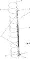
- reference number 1 indicates overall the apparatus for transporting a device along a tower, subject of the present finding.
- the present apparatus 1 is intended to be advantageously installed on towers 2 with very high height (which for example can even reach 100 meters height), such as flare stacks of petrochemical plants, smokestacks of power production plants, pylons, etc., and in general on high structures whose top is not easily reachable by operators.
- the present apparatus 1 is intended to be employed for transporting devices 3 (such as light-emitting devices, smoke detection devices, flame ignition devices, etc.) onto the top of the tower 2 and for bringing such devices 3 back to the ground, without an operator having to be on the top of the tower 2 itself.
- devices 3 such as light-emitting devices, smoke detection devices, flame ignition devices, etc.
- the present apparatus 1 is employed for transporting, to the top of the tower 2, a light-signaling device adapted to signal the presence of the tower 2 to aircraft such as airplanes and helicopters.
- the present apparatus 1 is employed for transporting a flame ignition device (in the technical jargon of the field termed "pilot light") onto the top of the tower 2, for example constituted by the flare stack of a refinery.
- a flame ignition device in the technical jargon of the field termed "pilot light”
- the present apparatus 1 can be used for transporting to the top of a tower 2 any one device 3, such as smoke detection devices, surveillance devices, etc.
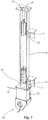
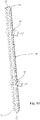
- the apparatus 1 comprises a rail 4 which is extended according to a guide direction X (in particular substantially rectilinear and vertical) between a lower end 5 thereof and an upper end 6 thereof.
- the rail 4 is provided with fixing means 7 (described in detail hereinbelow) by means of which it is susceptible to be fixed to the tower 2, with the upper end 6 of the rail 4 placed at the top of the tower 2 itself.
- the upper end 6 of the rail 4 is positioned below the top of the tower 2, preferably spaced from such top e.g. by about 3-5 meters.
- the rail 4 is substantially extended along the entire height of the tower 2 and has the lower end 5 thereof placed at the base of the tower 2 itself in order to allow bringing the device 3 back to the ground (as explained hereinbelow).
- the rail 4 is arranged along a final upper section of the tower 2, e.g. the final 15-20 meters from the top of the tower 2, being extended for example starting from the height of the tower 2 where the final operator-accessible positions are arranged.
- the lower end 5 of the rail 4 is arranged at the aforesaid operator-accessible positions.
- the apparatus 1 comprises a trolley 8 slidably constrained to the rail 4 and adapted to support the device 3 to be transported along the tower 2.
- the device 3 to be transported is provided with one or more power cables 9 which allow the operation of the device 3 itself.
- the power cable 9 of the latter is constituted for example by at least one electrical cable in order to provide the electrical energy necessary for turning on the light sources (for example constituted by LEDs) of the device itself.
- the electrical cable in particular is provided with a first end electrically connected to the light sources of the device and with a second end connected to an electrical energy source.
- the power cables 9 of the latter comprise for example a cable for providing the gas for feeding the flame of the ignition device; such cable is connected, at one end, to the device itself and, at the other end, to a combustible gas source on the ground.
- the power cables 9 of the ignition device comprise an electrical cable for power supplying and controlling electrical components of the device itself, such as an electric arc ignition component, connected to an electrical power supply and control unit placed on the ground.
- Each power cable 9 of the devices 3 is made of flexible material in order to allow winding the cable on the ground (e.g. around a corresponding winding roller) when the device 3 is brought to the ground, and for unwinding the cable 9 substantially along the entire height of the tower 2 when the device 3 is brought to the top of the tower 2 itself.
- the apparatus 1 also comprises movement means 10 mechanically connected to the trolley 8 and actuatable for moving the latter to slide along the rail 4 between a raised position, in which the trolley 8 is placed at the upper end 6 of the rail 4 in order to arrange the device 3 at the top of the tower 2 (where the device 3 is intended to operate), and a lowered position, in which the trolley 8 is placed at the lower end 5 of the rail 4 in order to bring the device 3 to the ground or to an access position (for example in order to execute maintenance or repair operations).
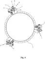
- Multiple apparatuses 1 are advantageously installable on the tower 2, each apparatus provided with a corresponding rail 4 and corresponding trolley 8 in order to transport a corresponding device 3, as illustrated for example in the embodiment of figure 4 .
- the rail 4 of the apparatus 1 comprises at least one hollow shaped profile 11 with elongated form, which is longitudinally extended according to the guide direction X between a lower edge 12 thereof, which delimits a first opening 12', and an upper edge 13 thereof, which delimits a second opening 13'.
- Each shaped profile 11 of the rail 4 is provided with an external surface 14 thereof and with an internal surface 15 thereof.
- the latter defines a guide seat 16 (being extended between the aforesaid openings 12', 13') in which the trolley 8 is slidably housed and in which the power cable 9 of the device 3 mounted on the trolley 8 itself is susceptible to pass.
- the rail 4 advantageously comprises multiple aforesaid shaped profiles 11 fixed to the tower 2 and arranged aligned with each other in succession along the guide direction X of the rail 4 itself.
- each shaped profile 11 is positioned with its upper edge 13 slightly spaced from the lower edge 12 of the subsequent shaped profile 11, e.g. by about 10 mm, in order to compensate for the length variations of each profile 11 due to the thermal expansion.
- each shaped profile 11 is connected to the subsequent profile by means of one or more alignment pins (not illustrated), inserted in corresponding holes obtained at the edges 12, 13 of the shaped profiles 11 in a manner so as to maintain the latter aligned with each other according to the guide direction X.
- the shaped profiles 11 provided with aforesaid guide seat 16 according to the present invention allow, when the trolley 8 is in the raised position, substantially housing at their interior the entire power cable 9 of the device 3 to be transported and, therefore, protecting the power cable 9 from external weathering agents (such as wind, rain, etc.) which would easily lead to wear and breakage.
- each shaped profile 11 is made of metal material, preferably aluminum, and is preferably obtained via extrusion.
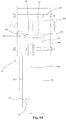
- the shaped profile 11 placed at the top of the tower 2 is made of steel in order to ensure that the heat developed by the combustion of the gases expelled by the smokestack does not at all deteriorate the integrity of such shaped profile 11.
- the shaped profile 11 at the upper end 6 of the rail 4 is positioned tilted with respect to the guide direction X, with the upper edge 13 of the shaped profile 11 closer to the tower 2 with respect to the lower edge 12, in a manner so as to bring the device 3 (constituted in such second embodiment by a pilot light) in proximity to the upper mouth of the tower 2, where the gases to be burned exit.
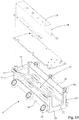
- the trolley 8 of the present apparatus 1 comprises a framework 17 preferably bearing a plurality of wheels 18 mounted thereon that are slidably engaged with the internal surface 15 of the shaped profiles 11 of the rail 4.
- the framework 17 of the trolley 8 is provided with at least one housing seat 19 adapted to contain, at its interior, at least one section of the power cable 9 of the device 3 mounted on the trolley 8 and in particular the end section of the cable 9 connected to the device 3 itself.
- the framework 17 of the trolley 8 is extended according to the guide direction X between a lower end part 20 thereof and an upper end part 21 thereof, respectively provided with a lower opening 22 and an upper opening 23 for the passage of the power cable 9 in the housing seat 19.
- the trolley 8 of the apparatus 1 comprises a support bracket 24 fixed to the framework 17 of the trolley 8 and adapted to bear, fixed thereon, the corresponding device 3 to be transported.
- the aforesaid support bracket 24 is provided with a connection portion 25 fixed to the framework 17 of the trolley 8 (e.g. by means of fixing screws, not illustrated), and with a projecting portion 26 (to which the device 3 is fixed) being extended outside the guide seat 16 of the shaped profiles 11 through a longitudinal slit 27 obtained on each shaped profile 11, in a manner so as to support the device 3 positioned outside the guide seat 16 of the profiles 11 themselves.
- the aforesaid longitudinal slit 27 is extended in a through manner between the lower edge 12 and the upper edge 13 of the corresponding shaped profile 11 according to the guide direction X of the rail 4, in a manner so as to allow the passage of the support bracket 24 of the trolley 8 during the sliding thereof between the lowered position and the raised position.
- the shaped profile 11 placed at the lower end 5 of the rail 4 is provided, on the lower edge 12 thereof, with a first end stop portion 28 placed as a lower closure of the corresponding longitudinal slit 27 and adapted to receive in abutment the support bracket 24 of the trolley 8 when the latter is brought into the lowered position.
- each shaped profile 11 placed at the upper end 6 of the rail 4 is advantageously provided, on the upper edge 13 thereof, with a second end stop portion 29 placed as an upper closure of the corresponding longitudinal slit 27 and adapted to receive in abutment the support bracket 24 of the trolley 8 when the latter is brought into the raised position.
- each shaped profile 11 of the rail 4 has substantially quadrangular cross section and is provided with a front wall 30, on which the aforesaid longitudinal slit 27 is obtained, with a rear wall 31 substantially facing the front wall 30, and with a first and a second lateral wall 32, 33 placed to connect the front 30 and rear 31 walls.
- the fixing means 7 of the rail 4, adapted to fix the latter to the tower 2 comprise a first connection portion 34 fixed to the external surface 14 of the rear wall 31 of each shaped profile 11, and a second connection portion 35 fixed to the external surface 14 of the first lateral wall 32 of the shaped profile 11 itself.
- Each shaped profile 11 of the rail 4 is selectively fixed to the tower 2 by means of the first connection portion 34 (as illustrated in the embodiment of figures 1-3 ) or by means of the second connection portion 35 (as illustrated in the embodiment of figures 4-5 ) in a manner so as to arrange the device 3 supported by the trolley 8 respectively on the opposite side of the tower 2 (with respect to the position of the rail 4) or alongside the tower 2 itself.
- the shaped profiles 11 of the rail 4 are fixed to the tower 2 by means of their first connection portions 34, in a manner such that their front walls 30, at which the trolley 8 supports the device 3, are directed in an opposite sense with respect to the tower 2 to ensure that the device 3 (advantageously constituted by the light signaling device) is more clearly visible to aircraft.
- the shaped profiles 11 of the rail 4 are fixed to the tower 2 (constituted by a smokestack) by means of their second connection portions 35, in a manner such that their front walls 30 (and thus the device 3 supported by the trolley 8) are arranged alongside the tower 2.
- the device 3 is arranged adjacent to the mouth of the smokestack in order to facilitate the ignition of the gases expelled by the latter.
- each connection portion 34, 35 of the shaped profiles 11 of the rail is provided with a longitudinal junction seat 34', 35' in which an anchorage plate 36 is selectively fixed, preferably via welding, which is in turn fixed, preferably by means of bolting, to an attachment bracket 37 anchored to the tower 2.
- each shaped profile 11 has substantially polygonal section (in particular substantially rectangular section) and delimits four internal corners 38 of the corresponding guide seat 16 in which the trolley 8 is susceptible to slide.
- the framework 17 of the trolley 8 has substantially parallelepiped form and is provided with at least four corners 39, along which corresponding rows of wheels 18 are arranged that are slidably engaged on the internal surface 15 of the shaped profile 11 at the respective internal corners 38 of the guide seat 16.
- the framework 17 of the trolley 8 comprises four angular plates 40, defining the corresponding corners 39, and connected with each other by the aforesaid lower end 20 and upper end 21 parts of the framework 17.
- each angular plate is oriented according to the diagonal of the cross section of the trolley and bears, mounted thereon, the corresponding row of small wheels arranged aligned with each other according to the guide direction of the rail.
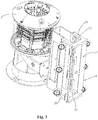
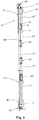
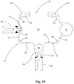
- the movement means 10 (which actuate the trolley 8 to slide along the rail 4 between its lowered position and raised position) comprise a pulley 41, which is provided with an actuation device 42 arranged at the lower end 5 of the rail 4, with a transmission pulley 43 fixed at the upper end 6 of the rail 4, and with a drive rope 44 supported on the transmission pulley 43.
- the drive rope 44 of the pulley 41 is provided with a first end 45 fixed to the actuation device 42 and with a second end 46 fixed to the trolley 8.
- the actuation device 42 can be actuated by an operator in order to move the drive rope 44, for the purpose of making the trolley 8 slide along the rail 4.
- the actuation device 42 of the pulley 41 advantageously comprises a winch provided with a winding drum, to which the first end 45 of the drive rope 44 is connected.
- the drum of the winch can be actuated by means of a motor or manually (e.g. through a crank) to rotate in order to unwind or wind the drive rope 44 so as to respectively lower or raise the trolley 8.
- each shaped profile 11 of the rail 4 is provided with a first passage seat 47, which is extended according to the guide direction X in a through manner between the lower edge 12 and the upper edge 13 of the corresponding shaped profile 11, and houses therein the first section 44' of the drive rope 44 (which is extended between the actuation device 42 and the transmission pulley 43) in a manner so as to protect such first section 44' of the drive rope 44.
- the first passage seat 47 of each shaped profile 11 is situated outside the guide seat 16 in which the trolley 8 is susceptible to slide.
- the first passage seat 47 is positioned on the second lateral wall 33 of the corresponding shaped profile 11, which in particular is positioned on the side opposite that of the first lateral wall 32, on which the second connection portion 35 of the fixing means 7 of the rail 4 is positioned.
- the second section 44" of the drive rope 44 is housed inside the guide seat 16 of the shaped profiles 11 of the rail 4, in a manner so as to protect such second section 44" from weathering agents.
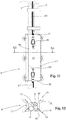
- the aforesaid coupling device 48 comprises a support body 49, integral with the rail 4 of the apparatus 1, and a lever 50 pivoted, by means of a first pin 54, to such support body 49 and provided with a hook-shaped retention end 51 and adapted to be engaged with the trolley 8 when the latter is brought into the raised position.
- the coupling device 48 comprises an actuation rope 52 being extended parallel to the guide direction X of the rail 4 between an (upper) third end 53' thereof, constrained to the lever 50, and a (lower) fourth end 53" thereof positioned at the lower end 5 of the rail 4 and advantageously constrained to a release lever 70 on which an operator can operate in order to rotate the lever 50 in a manner so as to release the retention end 51 of the latter from the trolley 8 (as described hereinbelow).
- the lever 50 of the coupling device 48 can be actuated to rotate around its first pin 54 between a coupling position, in which the retention end 51 of the lever 50 is susceptible to interfere with the trolley 8 in order to be engaged with the framework 17 thereof, and a release position, in which the retention end 51 of the lever 50 is rotated away from the trolley 8 in order to be uncoupled therefrom.
- the framework 17 of the trolley 8 comprises a grip portion 55 susceptible of being engaged with the retention end 51 of the lever 50 of the coupling device 48 and preferably placed at the upper end part 21 of the framework 17 of the trolley 8, in particular to partially delimit the upper opening 23 of the trolley 8 itself.
- the support body 49 of the coupling device 48 is fixed to the upper end 6 of the rail 4 and preferably comprises a cover casing, inside which the lever 50 is partially housed.
- transmission pulley 43 of the pulley 41 of the movement means 10 is housed.
- the lever 50 of the coupling device 48 comprises a first arm 56 provided with the aforesaid retention end 51 and being extended with such retention end 51 within the shaped profile 11 of the rail 4 in order to be engaged with the trolley 8 when the latter is brought into the raised position.
- the lever 50 is provided with a second arm 57, arranged tilted with respect to the first 56, preferably by about 90°, and at whose free end 57' the third end 53 of the actuation rope 52 of the coupling device 48 is constrained.
- the second arm 57 of the lever 50 is provided with a through hole through which the drive rope 44 of the pulley 41 passes, in a manner such that such second arm 57 does not block the movement of the drive rope 44 itself.
- the coupling device 48 comprises a spring 58, in particular helical, constrained at a first end thereof to the free end 57' of the second arm 57 of the lever 50 and, at a second end thereof, to the support body 49, and adapted to pull the lever 50 in order to rotate it into the coupling position.
- a spring 58 in particular helical, constrained at a first end thereof to the free end 57' of the second arm 57 of the lever 50 and, at a second end thereof, to the support body 49, and adapted to pull the lever 50 in order to rotate it into the coupling position.
- the spring 58 is hung with its second end on a support rod 59 fixed to the support body 49 of the coupling device 48 and positioned above the second arm 57 of the lever 50.
- the retention end 51 of the first arm 56 of the lever 50 is provided with a tapered surface 51', against which the grip portion 55 of the trolley 8 is susceptible to abut when the latter is brought into the raised position.
- the release lever 70 of the coupling device 48 (to which the lower fourth end 53" of the actuation rope 52 is constrained) is pivoted, by means of a second pin 71, to a support frame 72 advantageously fixed to the lower end 5 of the rail 4 and preferably arranged between such lower end 5 and the actuation device 42 of the pulley 41 of the apparatus 1.
- the support frame 72 comprises a fully hollow box-like body that is open at the top and bottom in order to allow the passage of the drive rope 44 of the pulley 41 connected to the underlying actuation device 42 of the pulley 41 itself.
- the release lever 70 is partially extended within the box-like body of the support frame 72 and is provided with one constrained end 73, hinged by means of the second pin 71 to the support frame 72, and with an opposite grip end 74 being extended outside the box-like body of the frame 72 through a passage opening 75 obtained on a lateral wall of the box-like body itself.
- the fourth end 53" of the actuation rope 52 is fixed to a section of the release lever 70 arranged between the constrained end 73 and the grip end 74 and preferably positioned inside the box-like body of the support frame 72.
- each shaped profile 11 of the rail 4 is provided with a second passage seat 60, which is extended according to the guide direction X in a through manner between the lower edge 12 and the upper edge 13 of the corresponding shaped profile 11 and houses therein the actuation rope 52 of the aforesaid coupling device 48.
- the actuation rope 52 is protected from the weathering agents with consequent reduction of the factors of wear and damage of the rope 52 itself.
- the second passage seat 60 of each shaped profile 11 is obtained on the rear wall 31 of the shaped profile 11 itself.
- the apparatus comprises at least one dimensional constraining element 61 wound around the external surface 14 of the corresponding shaped profile 11 of the rail 4, in order to limit the deformation of the transverse shape of the shaped profile 11 itself.
- each dimensional constraining element 61 is provided with an internal perimeter edge 62 substantially counter-shaped with respect to the cross section of the external surface 14 of the corresponding shaped profile 11, and placed substantially adjacent to such external surface 14 in order to prevent expansions via deformation of the shaped profile 11.
- each constraining element 61 is extended around the corresponding shaped profile 11 with a substantially C-shaped form, and is provided with a lateral opening 63 placed across from the longitudinal slit 27 of the corresponding shaped profile 11 in order to allow the passage of the support bracket 24 of the trolley 8.
- each constraining element 61 comprises a metal plate, positioned on a plane substantially orthogonal to the guide direction X of the rail 4 and preferably made of aluminum.
- each constraining element 61 is provided with at least one shaped appendage 64 inserted in a retention relation in a corresponding shaped seat 65 obtained on the external surface 14 of the corresponding shaped profile 11.
- each constraining element 61 is provided with two aforesaid shaped appendages 64, placed at the edges of the lateral opening 63, and inserted in two corresponding shaped seats 65 placed in proximity to the edges of the longitudinal slit 27 of the corresponding shaped profile 11.
- each constraining element 61 by means of its shaped appendages 64, prevents the narrowing of the transverse shape of the corresponding shaped profile 11, substantially preventing the edges of the longitudinal slit 27 of the shaped profile 11 from approaching each other.
- each shaped profile 11 multiple constraining elements 61 are mounted (e.g. two) that are spaced from each other along the longitudinal extension of the shaped profile 11 itself.
- each constraining element 61 is fixed, preferably via bolting, to the corresponding connection bracket 37 by means of which the shaped profile 11 is fixed to the tower 2.
- the shaped profiles 11 of the apparatus 1 according to the present invention allow obtaining the rail 4 by means of profiles made of aluminum, preferably extruded, allowing considerable production cost savings with respect to the rails made of iron or steel of the apparatuses of known type, commented on above.
- the constraining elements 61 confer to the shaped profiles 11 a suitable dimensional stability, and more generally a mechanical resistance to deformations, especially due to thermal expansion, ensuring the regular sliding of the trolley 8 in the guide seat 16 of the shaped profiles 11.
- the present apparatus 1 comprises multiple auxiliary trolleys 66 arranged in succession one after the other in the guide seat 16 of the shaped profiles 11 of the rail 4 and positioned below the aforesaid trolley 8 that bears, mounted thereon, the device 3 to be transported along the tower 2.
- Such auxiliary trolleys 66 are connected to each other by means of a corresponding connection rope 67.
- the first auxiliary trolley 66' of the succession (placed higher) is connected to the trolley 8 on which the device 3 is mounted, by means of a corresponding head connection rope 67'.
- the framework 17 of the trolley 8 is provided with a first coupling appendage 68 to which the second end 46 of the drive rope 44 of the pulley 41 is fixed, and with a second coupling appendage 69 to which the head connection rope 67' is fixed.
- the aforesaid coupling appendages 68, 69 are projectingly extended within the housing seat 19 of the framework 17 of the trolley 8, and are fixed, in particular integrally, with the corresponding angular plates 40 of the framework 17 itself.
- the auxiliary trolleys 66, 66' of the apparatus have structural characteristics that are substantially identical to those of the trolley 8 on which the device 3 is mounted.
- Each auxiliary trolley 66, 66' is provided with a corresponding auxiliary housing seat, which advantageously is substantially equivalent to the housing seat 19 of the trolley 8, and is traversed by the power cable 9 of the device 3 mounted on the trolley 8, in a manner such to limit the oscillations of the power cable 9 itself, thus preventing strong impact against the tubular profiles and thus preventing damage of the same power cable.
- the auxiliary trolleys 66, 66' do not bear any device mounted thereon; rather, they only perform the aforesaid function of guiding the power cable 9 of the device 3 mounted on the trolley 8.
- the invention thus conceived therefore attains the pre-established objects.
Landscapes
- Engineering & Computer Science (AREA)
- Structural Engineering (AREA)
- General Engineering & Computer Science (AREA)
- Civil Engineering (AREA)
- Mechanical Engineering (AREA)
- Transportation (AREA)
- Automation & Control Theory (AREA)
- Carriers, Traveling Bodies, And Overhead Traveling Cranes (AREA)
Claims (10)
- Vorrichtung (1) zum Transport einer Vorrichtung entlang eines Turms, die Folgendes umfasst:- mindestens eine Schiene (4), die entlang einer im Wesentlichen geradlinigen Führungsrichtung (X) zwischen einem unteren Ende (5) und einem oberen Ende (6) verläuft und mit Befestigungselementen (7) ausgestattet ist, mittels derer die genannte Schiene (4) an einem Turm (2) befestigt werden kann, wobei das obere Ende (6) auf der Oberseite des genannten Turms (2) positioniert ist;- wenigstens einen gleitend mit der genannten Schiene (4) verbundenen Schlitten (8), der geeignet ist, eine zu transportierende Vorrichtung (3) zu tragen, die mit mindestens einem Versorgungskabel (9) ausgestattet ist;- mechanisch an dem genannten Schlitten (8) befestigte Bewegungselemente (10), die betätigt werden können, um den genannten Schlitten (8) gleitend entlang der genannten Schiene (4) zwischen einer gesenkten Position, in der der genannte Schlitten (8) auf dem unteren Ende (5) der genannten Schiene (4) positioniert ist, und einer angehobenen Position, in der der genannte Schlitten (8) auf dem oberen Ende (6) der genannten Schiene (4) positioniert ist, zu bewegen, um die genannte Vorrichtung (3) auf der Oberseite des genannten Turms (2) anzuordnen;wobei die genannte Schiene (4) mindestens ein hohles Formprofil (11) mit länglicher Form umfasst, das längs entlang der genannten Führungsrichtung (X) zwischen einem unteren Rand (12) und einem oberen Rand (13) verläuft und mit einer Außenfläche (14) und einer Innenfläche (15) ausgestattet ist, die einen Führungssitz (16) definiert, in den der genannte Schlitten (8) gleitend eingesetzt ist und in dem das Versorgungskabel (9) der genannten Vorrichtung (3) verlaufen kann; wobei der genannte Schlitten (8) eine mit einem vorstehenden Teil (26) ausgestattete Halterung (24) umfasst, an der die genannte Vorrichtung (3) befestigt werden kann; wobei der genannte vorstehende Teil (26) sich an der Außenseite des Führungssitzes (16) des genannten Formprofils (11) über einen auf dem genannten Formprofil (11) befindlichen und parallel zu der genannten Führungsrichtung (X) verlaufenden Längsschlitz (27) erstreckt;
bei der die genannten Bewegungselemente (10) mindestens einen mit einer auf dem unteren Ende (5) der genannten Schiene (4) angeordneten Betätigungsvorrichtung (42), einer auf dem oberen Ende (6) der genannten Schiene (4) befestigten Umlenkscheibe (43) und einem auf der genannten Umlenkscheibe (43) aufliegenden Zugseil (44) und mit einem ersten an der genannten Betätigungsvorrichtung (42) befestigten Ende (45) und einem zweiten an dem genannten Schlitten (8) befestigten Ende (46) ausgestatteten Flaschenzug (41) umfassen; wobei das genannte Zugseil (44) mit einem ersten, parallel zu der genannten Führungsrichtung (X) zwischen der genannten Betätigungsvorrichtung (42) und der genannten Umlenkscheibe (43) verlaufenden Abschnitt (44') und einem zweiten, parallel zu der genannten Führungsrichtung (X) zwischen der genannten Umlenkscheibe (43) und dem genannten Schlitten (8) verlaufenden Abschnitt ausgestattet ist; wobei die genannte Vorrichtung (1) dadurch gekennzeichnet ist, dass das Formprofil (11) der genannten Schiene (4) mit mindestens einem durchgehend zwischen dem unteren Rand (12) und dem oberen Rand (13) des genannten Formprofils (11) entlang der Führungsrichtung (X) verlaufenden ersten Durchgangssitz (47) ausgestattet ist, in dessen Innerem der erste Abschnitt (44') des genannten Zugseils (44) untergebracht ist. - Vorrichtung (1) nach Anspruch 1, dadurch gekennzeichnet, dass der genannte Schlitten (8) einen mit mindestens einem Unterbringungssitz (19) ausgestatteten Rahmen (17) umfasst, der geeignet ist, in seinem Inneren mindestens einen Abschnitt des Versorgungskabels (9) der genannten Vorrichtung (3) zu enthalten.
- Vorrichtung (1) nach einem beliebigen der vorangegangenen Ansprüche, dadurch gekennzeichnet, dass sie mindestens eine auf dem oberen Ende (6) der genannten Schiene (4) angeordnete Befestigungsvorrichtung (48) umfasst, die betätigt werden kann, um sich mit dem genannten Schlitten (8) in der genannten angehobenen Position zu verbinden.
- Vorrichtung (1) nach Anspruch 3, dadurch gekennzeichnet dass die genannte Befestigungsvorrichtung (48) einen an der genannten Schiene (4) befestigten Trägerkörper (49), einen an dem genannten Trägerkörper (49) verschraubten und mit einem hakenförmigen Rückhalteende (51) ausgestatteten Hebel (50), der geeignet ist, sich mit dem genannten Schlitten (8) zu verbinden, und ein parallel zu der genannten Führungsrichtung (X) verlaufendes und mit einem dritten, an dem genannten Hebel (50) befestigten Ende (53') und einem vierten, auf dem unteren Ende (5) der genannten Schiene (4) positionierten Ende ausgestattetes Betätigungsseil (52) umfasst; wobei das genannte Formprofil (11) mit einem zweiten durchgehend zwischen dem unteren Rand (12) und dem oberen Rand (13) des genannten Formprofils (11) entlang der Führungsrichtung (X) verlaufenden Durchgangssitz (60) ausgestattet ist, in dessen Innerem das Betätigungsseil (52) der genannten Befestigungsvorrichtung (48) untergebracht ist.
- Vorrichtung (1) nach einem beliebigen der vorangegangenen Ansprüche, dadurch gekennzeichnet, dass das Formprofil (11) der genannten Schiene (4) mit einer vorderen Wand (30), auf der sich der genannte Längsschlitz (27) befindet, mit einer im Wesentlichen der genannten vorderen Wand (30) gegenüberliegenden Rückwand (31) und mit einer ersten und einer zweiten Seitenwand (32, 33) ausgestattet ist, die der Verbindung der genannten vorderen Wand (30) und Rückwand (31) dienen;
wobei die Befestigungselemente (7) der genannten Schiene (4) einen ersten, an der Außenfläche (14) der Rückwand (31) des genannten Formprofils (11) angebrachten Befestigungsabschnitt (34) und einen zweiten, an der Außenfläche (14) der ersten Seitenwand (32) des genannten Formprofils (11) angebrachten Befestigungsabschnitt (35) umfassen. - Vorrichtung (1) nach einem beliebigen der vorangegangenen Ansprüche, dadurch gekennzeichnet, dass sie mindestens ein Element zur dimensionalen Bindung (61) um die Außenfläche (14) des genannten Formprofils (11) herum umfassen.
- Vorrichtung (1) nach Anspruch 6, dadurch gekennzeichnet, dass das genannte Bindungselement (61) mit einem inneren, im Wesentlichen im Verhältnis zum Querschnitt der Außenfläche (14) des genannten Formprofils (11) ein Gegenprofil bildenden und im Wesentlichen an die genannte Außenfläche (14) angrenzenden umlaufenden Rand (62) ausgestattet ist.
- Vorrichtung (1) nach Anspruch 7, dadurch gekennzeichnet, dass der innere umlaufende Rand (62) des genannten Bindungselements (61) mit mindestens einem, in einem Rückhalteverhältnis in einen entsprechenden, auf der Außenfläche (14) des genannten Formprofils (11) befindlichen Profilsitz (65) eingesetzten Zusatzprofil (64) ausgestattet ist.
- Vorrichtung (1) nach einem beliebigen der vorangegangenen Ansprüche, dadurch gekennzeichnet, dass sie mehrere Hilfsschlitten (66) umfasst, die der Reihe nach einer nach dem anderen in dem Führungssitz (16) des genannten mindestens einen Formprofils (11) angeordnet, unter dem genannten Schlitten (8) positioniert und einer mit dem nächsten mit Hilfe eines entsprechenden Verbindungsseils (67) verbunden sind; wobei die genannten Hilfsschlitten (66) einen ersten, mit dem genannten Schlitten (8) mit einem entsprechenden Kopfverbindungsseil (67') verbundenen Hilfsschlitten (66') umfassen.
- Vorrichtung (1) nach Anspruch 9, dadurch gekennzeichnet, dass jeder genannte Hilfsschlitten (66, 66') mit einem entsprechenden Hilfsunterbringungssitz ausgestattet ist, der geeignet ist, von dem Versorgungskabel (9) der genannten Vorrichtung (3) überquert zu werden.
Applications Claiming Priority (1)
| Application Number | Priority Date | Filing Date | Title |
|---|---|---|---|
| ITPD20140056 | 2014-03-10 |
Publications (2)
| Publication Number | Publication Date |
|---|---|
| EP2918537A1 EP2918537A1 (de) | 2015-09-16 |
| EP2918537B1 true EP2918537B1 (de) | 2017-09-27 |
Family
ID=50897794
Family Applications (1)
| Application Number | Title | Priority Date | Filing Date |
|---|---|---|---|
| EP15158314.3A Not-in-force EP2918537B1 (de) | 2014-03-10 | 2015-03-09 | Vorrichtung zum Transport einer Vorrichtung entlang eines Turms |
Country Status (3)
| Country | Link |
|---|---|
| US (1) | US9664337B2 (de) |
| EP (1) | EP2918537B1 (de) |
| CA (1) | CA2884213C (de) |
Families Citing this family (9)
| Publication number | Priority date | Publication date | Assignee | Title |
|---|---|---|---|---|
| NL2011863C2 (en) * | 2013-11-29 | 2015-06-01 | Linear Adjustment Dev Ltd | Driving device for a support column. |
| US10323623B2 (en) | 2016-10-25 | 2019-06-18 | General Electric Company | System and method for transporting or storing wind turbine tower sections |
| CN106402616B (zh) * | 2016-11-21 | 2019-01-29 | 宁波吉利汽车研究开发有限公司 | 车辆碰撞试验用摄像采集装置 |
| CA3039357A1 (en) * | 2018-04-11 | 2019-10-11 | C&E Group S.R.L. | Apparatus for the transport of a device along a construction |
| AU2019410394B2 (en) * | 2018-12-20 | 2023-06-15 | Inventio Ag | Lift rail |
| CN110881255B (zh) * | 2019-10-14 | 2022-04-29 | 国网信息通信产业集团有限公司北京分公司 | 一种多站融合设备的防护装置 |
| CN113358318B (zh) * | 2021-07-02 | 2022-05-17 | 中国空气动力研究与发展中心低速空气动力研究所 | 一种线缆碰撞检测方法、装置、设备及存储介质 |
| KR102437787B1 (ko) * | 2022-04-11 | 2022-08-29 | 동양검사기술주식회사 | Co-60 선원을 이용한 핫셀 차폐벽의 차폐성능 검사장치 |
| CN115254504A (zh) * | 2022-08-18 | 2022-11-01 | 中国大唐集团科学技术研究院有限公司中南电力试验研究院 | 一种风电塔筒喷漆维护机构 |
Family Cites Families (12)
| Publication number | Priority date | Publication date | Assignee | Title |
|---|---|---|---|---|
| US3517774A (en) | 1968-01-17 | 1970-06-30 | Roy E Meyer | Tower elevator |
| US3908801A (en) * | 1974-03-13 | 1975-09-30 | Vertical Transport Company | Vertical hoist assembly |
| GB2025363B (en) * | 1978-03-20 | 1982-12-22 | Qualter Hall & Co Ltd | Drop back catch assembly |
| CA1212618A (en) * | 1982-10-07 | 1986-10-14 | Roderick J. Macdonald | Flare stack ignitor |
| CA2054810C (en) * | 1991-11-01 | 1997-10-14 | Tornado Flare Systems (Canada) Inc. | Stack igniter |
| US5429496A (en) * | 1993-07-20 | 1995-07-04 | National Tank Company | Portable flare boom capable of being easily raised and lowered to change the flaring assembly |
| US5803726A (en) * | 1996-10-04 | 1998-09-08 | Bacon; David W. | Retractable, electric arc-ignited gas pilot for igniting flare stacks |
| CA2189095C (en) * | 1996-10-29 | 2004-10-19 | Gilles Roy | Fall prevention system for top mount antenna |
| US20080310948A1 (en) * | 2007-06-15 | 2008-12-18 | Margaret Platt Borgen | Material moving device and method |
| DK2195488T3 (da) * | 2007-09-11 | 2013-05-27 | Highstep Systems Ag | Forbindelse mellem føringsskinner |
| ES2360779B1 (es) * | 2009-11-20 | 2012-04-19 | Gamesa Innovation & Technology S.L | Aerogenerador con dispositivos internos de transporte. |
| US20120183381A1 (en) * | 2011-01-18 | 2012-07-19 | William Gordon | Cargo Lift System |
-
2015
- 2015-03-09 EP EP15158314.3A patent/EP2918537B1/de not_active Not-in-force
- 2015-03-09 CA CA2884213A patent/CA2884213C/en active Active
- 2015-03-09 US US14/641,440 patent/US9664337B2/en active Active
Non-Patent Citations (1)
| Title |
|---|
| None * |
Also Published As
| Publication number | Publication date |
|---|---|
| CA2884213A1 (en) | 2015-09-10 |
| EP2918537A1 (de) | 2015-09-16 |
| US20150252943A1 (en) | 2015-09-10 |
| CA2884213C (en) | 2022-10-04 |
| US9664337B2 (en) | 2017-05-30 |
Similar Documents
| Publication | Publication Date | Title |
|---|---|---|
| EP2918537B1 (de) | Vorrichtung zum Transport einer Vorrichtung entlang eines Turms | |
| AU2016204677B2 (en) | Lifting apparatus for highly mounted equipment | |
| US20150246792A1 (en) | Elevator car with a maintenance window | |
| US9580283B2 (en) | Method and system for installation and removal of ballast | |
| KR20100027279A (ko) | 휴대용 착탈식작동기 | |
| CN102918207A (zh) | 具有直升机起降坪的风力机 | |
| US20180002147A1 (en) | Solar array lifter and method | |
| US20140374679A1 (en) | Cable installation apparatus for mounting on a flanged structure | |
| CN101525102A (zh) | 用于在升降机中限制水平运动的系统 | |
| CN107938725B (zh) | 一种地下综合管廊巡检机器人升降平台及其控制方法 | |
| WO2016175339A1 (ko) | 풍력발전기의 유지보수용 작업대 | |
| KR101846788B1 (ko) | 발전용 보일러 수냉벽 긴급 보수용 조립식 곤도라 시스템 및 사용방법 | |
| KR101028631B1 (ko) | 이동식 교량점검장치 | |
| KR20120121976A (ko) | 신호등 승강장치 | |
| KR20170135756A (ko) | 승강로 하부피트에 설치되어지는 안전장치 | |
| KR20230119997A (ko) | 공중 헬기의 안전 착륙 시스템 | |
| CN106760882A (zh) | 升降系统 | |
| KR20150137132A (ko) | 풍력발전기의 나셀의 내부 기계 교체 및 보수 시스템 | |
| KR101451093B1 (ko) | 리니어 가이드 장치를 이용한 교량 등 설치대 | |
| ITPD20140020U1 (it) | Apparato per il trasporto di un dispositivo lungo una torre | |
| JP2011112052A (ja) | ナセル及び機器を備えた集合体 | |
| US10961083B2 (en) | Apparatus for the transport of a device along a construction | |
| GB2044221A (en) | Arrangement for maintenance of equipment at the top of a tower | |
| KR200478137Y1 (ko) | 풍력타워 설치용 가이드 | |
| KR102243951B1 (ko) | 가공송전선 안전거리 이격가능 지지기구 |
Legal Events
| Date | Code | Title | Description |
|---|---|---|---|
| PUAI | Public reference made under article 153(3) epc to a published international application that has entered the european phase |
Free format text: ORIGINAL CODE: 0009012 |
|
| AK | Designated contracting states |
Kind code of ref document: A1 Designated state(s): AL AT BE BG CH CY CZ DE DK EE ES FI FR GB GR HR HU IE IS IT LI LT LU LV MC MK MT NL NO PL PT RO RS SE SI SK SM TR |
|
| AX | Request for extension of the european patent |
Extension state: BA ME |
|
| 17P | Request for examination filed |
Effective date: 20160315 |
|
| RBV | Designated contracting states (corrected) |
Designated state(s): AL AT BE BG CH CY CZ DE DK EE ES FI FR GB GR HR HU IE IS IT LI LT LU LV MC MK MT NL NO PL PT RO RS SE SI SK SM TR |
|
| GRAP | Despatch of communication of intention to grant a patent |
Free format text: ORIGINAL CODE: EPIDOSNIGR1 |
|
| INTG | Intention to grant announced |
Effective date: 20170418 |
|
| GRAS | Grant fee paid |
Free format text: ORIGINAL CODE: EPIDOSNIGR3 |
|
| GRAA | (expected) grant |
Free format text: ORIGINAL CODE: 0009210 |
|
| AK | Designated contracting states |
Kind code of ref document: B1 Designated state(s): AL AT BE BG CH CY CZ DE DK EE ES FI FR GB GR HR HU IE IS IT LI LT LU LV MC MK MT NL NO PL PT RO RS SE SI SK SM TR |
|
| REG | Reference to a national code |
Ref country code: GB Ref legal event code: FG4D |
|
| REG | Reference to a national code |
Ref country code: CH Ref legal event code: EP |
|
| REG | Reference to a national code |
Ref country code: AT Ref legal event code: REF Ref document number: 931730 Country of ref document: AT Kind code of ref document: T Effective date: 20171015 |
|
| REG | Reference to a national code |
Ref country code: IE Ref legal event code: FG4D |
|
| REG | Reference to a national code |
Ref country code: DE Ref legal event code: R096 Ref document number: 602015004936 Country of ref document: DE |
|
| PG25 | Lapsed in a contracting state [announced via postgrant information from national office to epo] |
Ref country code: LT Free format text: LAPSE BECAUSE OF FAILURE TO SUBMIT A TRANSLATION OF THE DESCRIPTION OR TO PAY THE FEE WITHIN THE PRESCRIBED TIME-LIMIT Effective date: 20170927 Ref country code: HR Free format text: LAPSE BECAUSE OF FAILURE TO SUBMIT A TRANSLATION OF THE DESCRIPTION OR TO PAY THE FEE WITHIN THE PRESCRIBED TIME-LIMIT Effective date: 20170927 Ref country code: SE Free format text: LAPSE BECAUSE OF FAILURE TO SUBMIT A TRANSLATION OF THE DESCRIPTION OR TO PAY THE FEE WITHIN THE PRESCRIBED TIME-LIMIT Effective date: 20170927 Ref country code: NO Free format text: LAPSE BECAUSE OF FAILURE TO SUBMIT A TRANSLATION OF THE DESCRIPTION OR TO PAY THE FEE WITHIN THE PRESCRIBED TIME-LIMIT Effective date: 20171227 Ref country code: FI Free format text: LAPSE BECAUSE OF FAILURE TO SUBMIT A TRANSLATION OF THE DESCRIPTION OR TO PAY THE FEE WITHIN THE PRESCRIBED TIME-LIMIT Effective date: 20170927 |
|
| REG | Reference to a national code |
Ref country code: NL Ref legal event code: MP Effective date: 20170927 |
|
| REG | Reference to a national code |
Ref country code: LT Ref legal event code: MG4D |
|
| REG | Reference to a national code |
Ref country code: AT Ref legal event code: MK05 Ref document number: 931730 Country of ref document: AT Kind code of ref document: T Effective date: 20170927 |
|
| PG25 | Lapsed in a contracting state [announced via postgrant information from national office to epo] |
Ref country code: BG Free format text: LAPSE BECAUSE OF FAILURE TO SUBMIT A TRANSLATION OF THE DESCRIPTION OR TO PAY THE FEE WITHIN THE PRESCRIBED TIME-LIMIT Effective date: 20171227 Ref country code: LV Free format text: LAPSE BECAUSE OF FAILURE TO SUBMIT A TRANSLATION OF THE DESCRIPTION OR TO PAY THE FEE WITHIN THE PRESCRIBED TIME-LIMIT Effective date: 20170927 Ref country code: GR Free format text: LAPSE BECAUSE OF FAILURE TO SUBMIT A TRANSLATION OF THE DESCRIPTION OR TO PAY THE FEE WITHIN THE PRESCRIBED TIME-LIMIT Effective date: 20171228 Ref country code: RS Free format text: LAPSE BECAUSE OF FAILURE TO SUBMIT A TRANSLATION OF THE DESCRIPTION OR TO PAY THE FEE WITHIN THE PRESCRIBED TIME-LIMIT Effective date: 20170927 |
|
| REG | Reference to a national code |
Ref country code: FR Ref legal event code: PLFP Year of fee payment: 4 |
|
| PG25 | Lapsed in a contracting state [announced via postgrant information from national office to epo] |
Ref country code: NL Free format text: LAPSE BECAUSE OF FAILURE TO SUBMIT A TRANSLATION OF THE DESCRIPTION OR TO PAY THE FEE WITHIN THE PRESCRIBED TIME-LIMIT Effective date: 20170927 |
|
| PG25 | Lapsed in a contracting state [announced via postgrant information from national office to epo] |
Ref country code: RO Free format text: LAPSE BECAUSE OF FAILURE TO SUBMIT A TRANSLATION OF THE DESCRIPTION OR TO PAY THE FEE WITHIN THE PRESCRIBED TIME-LIMIT Effective date: 20170927 Ref country code: CZ Free format text: LAPSE BECAUSE OF FAILURE TO SUBMIT A TRANSLATION OF THE DESCRIPTION OR TO PAY THE FEE WITHIN THE PRESCRIBED TIME-LIMIT Effective date: 20170927 Ref country code: ES Free format text: LAPSE BECAUSE OF FAILURE TO SUBMIT A TRANSLATION OF THE DESCRIPTION OR TO PAY THE FEE WITHIN THE PRESCRIBED TIME-LIMIT Effective date: 20170927 |
|
| PG25 | Lapsed in a contracting state [announced via postgrant information from national office to epo] |
Ref country code: EE Free format text: LAPSE BECAUSE OF FAILURE TO SUBMIT A TRANSLATION OF THE DESCRIPTION OR TO PAY THE FEE WITHIN THE PRESCRIBED TIME-LIMIT Effective date: 20170927 Ref country code: SM Free format text: LAPSE BECAUSE OF FAILURE TO SUBMIT A TRANSLATION OF THE DESCRIPTION OR TO PAY THE FEE WITHIN THE PRESCRIBED TIME-LIMIT Effective date: 20170927 Ref country code: IS Free format text: LAPSE BECAUSE OF FAILURE TO SUBMIT A TRANSLATION OF THE DESCRIPTION OR TO PAY THE FEE WITHIN THE PRESCRIBED TIME-LIMIT Effective date: 20180127 Ref country code: AT Free format text: LAPSE BECAUSE OF FAILURE TO SUBMIT A TRANSLATION OF THE DESCRIPTION OR TO PAY THE FEE WITHIN THE PRESCRIBED TIME-LIMIT Effective date: 20170927 Ref country code: SK Free format text: LAPSE BECAUSE OF FAILURE TO SUBMIT A TRANSLATION OF THE DESCRIPTION OR TO PAY THE FEE WITHIN THE PRESCRIBED TIME-LIMIT Effective date: 20170927 |
|
| REG | Reference to a national code |
Ref country code: DE Ref legal event code: R097 Ref document number: 602015004936 Country of ref document: DE |
|
| PG25 | Lapsed in a contracting state [announced via postgrant information from national office to epo] |
Ref country code: DK Free format text: LAPSE BECAUSE OF FAILURE TO SUBMIT A TRANSLATION OF THE DESCRIPTION OR TO PAY THE FEE WITHIN THE PRESCRIBED TIME-LIMIT Effective date: 20170927 |
|
| PLBE | No opposition filed within time limit |
Free format text: ORIGINAL CODE: 0009261 |
|
| STAA | Information on the status of an ep patent application or granted ep patent |
Free format text: STATUS: NO OPPOSITION FILED WITHIN TIME LIMIT |
|
| PG25 | Lapsed in a contracting state [announced via postgrant information from national office to epo] |
Ref country code: PL Free format text: LAPSE BECAUSE OF FAILURE TO SUBMIT A TRANSLATION OF THE DESCRIPTION OR TO PAY THE FEE WITHIN THE PRESCRIBED TIME-LIMIT Effective date: 20170927 |
|
| 26N | No opposition filed |
Effective date: 20180628 |
|
| REG | Reference to a national code |
Ref country code: CH Ref legal event code: PL |
|
| PG25 | Lapsed in a contracting state [announced via postgrant information from national office to epo] |
Ref country code: SI Free format text: LAPSE BECAUSE OF FAILURE TO SUBMIT A TRANSLATION OF THE DESCRIPTION OR TO PAY THE FEE WITHIN THE PRESCRIBED TIME-LIMIT Effective date: 20170927 Ref country code: MC Free format text: LAPSE BECAUSE OF FAILURE TO SUBMIT A TRANSLATION OF THE DESCRIPTION OR TO PAY THE FEE WITHIN THE PRESCRIBED TIME-LIMIT Effective date: 20170927 |
|
| REG | Reference to a national code |
Ref country code: BE Ref legal event code: MM Effective date: 20180331 |
|
| REG | Reference to a national code |
Ref country code: IE Ref legal event code: MM4A |
|
| PG25 | Lapsed in a contracting state [announced via postgrant information from national office to epo] |
Ref country code: LU Free format text: LAPSE BECAUSE OF NON-PAYMENT OF DUE FEES Effective date: 20180309 |
|
| PG25 | Lapsed in a contracting state [announced via postgrant information from national office to epo] |
Ref country code: IE Free format text: LAPSE BECAUSE OF NON-PAYMENT OF DUE FEES Effective date: 20180309 |
|
| PG25 | Lapsed in a contracting state [announced via postgrant information from national office to epo] |
Ref country code: BE Free format text: LAPSE BECAUSE OF NON-PAYMENT OF DUE FEES Effective date: 20180331 Ref country code: LI Free format text: LAPSE BECAUSE OF NON-PAYMENT OF DUE FEES Effective date: 20180331 Ref country code: CH Free format text: LAPSE BECAUSE OF NON-PAYMENT OF DUE FEES Effective date: 20180331 |
|
| PG25 | Lapsed in a contracting state [announced via postgrant information from national office to epo] |
Ref country code: MT Free format text: LAPSE BECAUSE OF NON-PAYMENT OF DUE FEES Effective date: 20180309 |
|
| PG25 | Lapsed in a contracting state [announced via postgrant information from national office to epo] |
Ref country code: TR Free format text: LAPSE BECAUSE OF FAILURE TO SUBMIT A TRANSLATION OF THE DESCRIPTION OR TO PAY THE FEE WITHIN THE PRESCRIBED TIME-LIMIT Effective date: 20170927 |
|
| PG25 | Lapsed in a contracting state [announced via postgrant information from national office to epo] |
Ref country code: PT Free format text: LAPSE BECAUSE OF FAILURE TO SUBMIT A TRANSLATION OF THE DESCRIPTION OR TO PAY THE FEE WITHIN THE PRESCRIBED TIME-LIMIT Effective date: 20170927 |
|
| PG25 | Lapsed in a contracting state [announced via postgrant information from national office to epo] |
Ref country code: MK Free format text: LAPSE BECAUSE OF NON-PAYMENT OF DUE FEES Effective date: 20170927 Ref country code: CY Free format text: LAPSE BECAUSE OF FAILURE TO SUBMIT A TRANSLATION OF THE DESCRIPTION OR TO PAY THE FEE WITHIN THE PRESCRIBED TIME-LIMIT Effective date: 20170927 Ref country code: HU Free format text: LAPSE BECAUSE OF FAILURE TO SUBMIT A TRANSLATION OF THE DESCRIPTION OR TO PAY THE FEE WITHIN THE PRESCRIBED TIME-LIMIT; INVALID AB INITIO Effective date: 20150309 |
|
| PG25 | Lapsed in a contracting state [announced via postgrant information from national office to epo] |
Ref country code: AL Free format text: LAPSE BECAUSE OF FAILURE TO SUBMIT A TRANSLATION OF THE DESCRIPTION OR TO PAY THE FEE WITHIN THE PRESCRIBED TIME-LIMIT Effective date: 20170927 |
|
| PGFP | Annual fee paid to national office [announced via postgrant information from national office to epo] |
Ref country code: FR Payment date: 20230324 Year of fee payment: 9 |
|
| PGFP | Annual fee paid to national office [announced via postgrant information from national office to epo] |
Ref country code: DE Payment date: 20230321 Year of fee payment: 9 |
|
| P01 | Opt-out of the competence of the unified patent court (upc) registered |
Effective date: 20230307 |
|
| PGFP | Annual fee paid to national office [announced via postgrant information from national office to epo] |
Ref country code: GB Payment date: 20240320 Year of fee payment: 10 |
|
| PGFP | Annual fee paid to national office [announced via postgrant information from national office to epo] |
Ref country code: IT Payment date: 20240327 Year of fee payment: 10 |
|
| REG | Reference to a national code |
Ref country code: DE Ref legal event code: R119 Ref document number: 602015004936 Country of ref document: DE |
|
| PG25 | Lapsed in a contracting state [announced via postgrant information from national office to epo] |
Ref country code: DE Free format text: LAPSE BECAUSE OF NON-PAYMENT OF DUE FEES Effective date: 20241001 |
|
| PG25 | Lapsed in a contracting state [announced via postgrant information from national office to epo] |
Ref country code: FR Free format text: LAPSE BECAUSE OF NON-PAYMENT OF DUE FEES Effective date: 20240331 |
|
| PG25 | Lapsed in a contracting state [announced via postgrant information from national office to epo] |
Ref country code: FR Free format text: LAPSE BECAUSE OF NON-PAYMENT OF DUE FEES Effective date: 20240331 Ref country code: DE Free format text: LAPSE BECAUSE OF NON-PAYMENT OF DUE FEES Effective date: 20241001 |
|
| GBPC | Gb: european patent ceased through non-payment of renewal fee |
Effective date: 20250309 |
|
| PG25 | Lapsed in a contracting state [announced via postgrant information from national office to epo] |
Ref country code: GB Free format text: LAPSE BECAUSE OF NON-PAYMENT OF DUE FEES Effective date: 20250309 |
|
| PG25 | Lapsed in a contracting state [announced via postgrant information from national office to epo] |
Ref country code: IT Free format text: LAPSE BECAUSE OF NON-PAYMENT OF DUE FEES Effective date: 20250309 |