EP2918343A2 - Ihc, tissue slide fluid exchange disposable and system - Google Patents
Ihc, tissue slide fluid exchange disposable and system Download PDFInfo
- Publication number
- EP2918343A2 EP2918343A2 EP15158134.5A EP15158134A EP2918343A2 EP 2918343 A2 EP2918343 A2 EP 2918343A2 EP 15158134 A EP15158134 A EP 15158134A EP 2918343 A2 EP2918343 A2 EP 2918343A2
- Authority
- EP
- European Patent Office
- Prior art keywords
- sample
- slide
- holder
- port
- substrate
- Prior art date
- Legal status (The legal status is an assumption and is not a legal conclusion. Google has not performed a legal analysis and makes no representation as to the accuracy of the status listed.)
- Granted
Links
- 239000012530 fluid Substances 0.000 title claims abstract description 102
- 238000004891 communication Methods 0.000 claims abstract description 38
- 238000011084 recovery Methods 0.000 claims abstract description 34
- 238000002347 injection Methods 0.000 claims abstract description 27
- 239000007924 injection Substances 0.000 claims abstract description 27
- 238000000034 method Methods 0.000 claims abstract description 11
- 239000000758 substrate Substances 0.000 claims description 52
- 239000012528 membrane Substances 0.000 claims description 17
- 239000000853 adhesive Substances 0.000 claims description 13
- 230000001070 adhesive effect Effects 0.000 claims description 13
- 238000007789 sealing Methods 0.000 claims description 8
- 238000011010 flushing procedure Methods 0.000 abstract description 9
- 238000003364 immunohistochemistry Methods 0.000 abstract description 6
- 238000003556 assay Methods 0.000 abstract description 5
- 238000002791 soaking Methods 0.000 abstract description 3
- 238000011049 filling Methods 0.000 abstract description 2
- 238000012800 visualization Methods 0.000 abstract description 2
- 239000000243 solution Substances 0.000 description 17
- 238000005406 washing Methods 0.000 description 15
- 238000011534 incubation Methods 0.000 description 13
- 229920001296 polysiloxane Polymers 0.000 description 9
- 230000006835 compression Effects 0.000 description 7
- 238000007906 compression Methods 0.000 description 7
- 239000002981 blocking agent Substances 0.000 description 5
- 230000000903 blocking effect Effects 0.000 description 5
- 239000003522 acrylic cement Substances 0.000 description 4
- 239000011521 glass Substances 0.000 description 4
- -1 polyethylene Polymers 0.000 description 4
- 229920002725 thermoplastic elastomer Polymers 0.000 description 4
- 239000004793 Polystyrene Substances 0.000 description 3
- 239000003153 chemical reaction reagent Substances 0.000 description 3
- 239000006260 foam Substances 0.000 description 3
- 229920002223 polystyrene Polymers 0.000 description 3
- 238000011160 research Methods 0.000 description 3
- 238000003860 storage Methods 0.000 description 3
- 238000012546 transfer Methods 0.000 description 3
- MYRTYDVEIRVNKP-UHFFFAOYSA-N 1,2-Divinylbenzene Chemical compound C=CC1=CC=CC=C1C=C MYRTYDVEIRVNKP-UHFFFAOYSA-N 0.000 description 2
- 239000004696 Poly ether ether ketone Substances 0.000 description 2
- 239000004698 Polyethylene Substances 0.000 description 2
- XUIMIQQOPSSXEZ-UHFFFAOYSA-N Silicon Chemical compound [Si] XUIMIQQOPSSXEZ-UHFFFAOYSA-N 0.000 description 2
- PPBRXRYQALVLMV-UHFFFAOYSA-N Styrene Chemical compound C=CC1=CC=CC=C1 PPBRXRYQALVLMV-UHFFFAOYSA-N 0.000 description 2
- NIXOWILDQLNWCW-UHFFFAOYSA-N acrylic acid group Chemical group C(C=C)(=O)O NIXOWILDQLNWCW-UHFFFAOYSA-N 0.000 description 2
- 238000000799 fluorescence microscopy Methods 0.000 description 2
- 238000011068 loading method Methods 0.000 description 2
- 239000000463 material Substances 0.000 description 2
- 229920002492 poly(sulfone) Polymers 0.000 description 2
- 229920000515 polycarbonate Polymers 0.000 description 2
- 239000004417 polycarbonate Substances 0.000 description 2
- 229920002530 polyetherether ketone Polymers 0.000 description 2
- 239000005020 polyethylene terephthalate Substances 0.000 description 2
- 229920000139 polyethylene terephthalate Polymers 0.000 description 2
- 229920001343 polytetrafluoroethylene Polymers 0.000 description 2
- 229920002981 polyvinylidene fluoride Polymers 0.000 description 2
- 102000004169 proteins and genes Human genes 0.000 description 2
- 108090000623 proteins and genes Proteins 0.000 description 2
- 229910052710 silicon Inorganic materials 0.000 description 2
- 239000010703 silicon Substances 0.000 description 2
- 239000004953 Aliphatic polyamide Substances 0.000 description 1
- 239000004642 Polyimide Substances 0.000 description 1
- 239000004743 Polypropylene Substances 0.000 description 1
- 230000004913 activation Effects 0.000 description 1
- 239000012790 adhesive layer Substances 0.000 description 1
- 229920003231 aliphatic polyamide Polymers 0.000 description 1
- 230000009830 antibody antigen interaction Effects 0.000 description 1
- 239000000427 antigen Substances 0.000 description 1
- 102000036639 antigens Human genes 0.000 description 1
- 108091007433 antigens Proteins 0.000 description 1
- 238000013459 approach Methods 0.000 description 1
- 239000004760 aramid Substances 0.000 description 1
- 229920003235 aromatic polyamide Polymers 0.000 description 1
- 125000003118 aryl group Chemical group 0.000 description 1
- 238000005452 bending Methods 0.000 description 1
- 239000000090 biomarker Substances 0.000 description 1
- 239000000919 ceramic Substances 0.000 description 1
- 238000010835 comparative analysis Methods 0.000 description 1
- 150000001875 compounds Chemical class 0.000 description 1
- 238000011109 contamination Methods 0.000 description 1
- 229920001577 copolymer Polymers 0.000 description 1
- 238000010586 diagram Methods 0.000 description 1
- 238000009826 distribution Methods 0.000 description 1
- 238000001035 drying Methods 0.000 description 1
- 230000003670 easy-to-clean Effects 0.000 description 1
- 239000000834 fixative Substances 0.000 description 1
- 150000004676 glycans Chemical class 0.000 description 1
- 230000036571 hydration Effects 0.000 description 1
- 238000006703 hydration reaction Methods 0.000 description 1
- 229920001477 hydrophilic polymer Polymers 0.000 description 1
- 238000002955 isolation Methods 0.000 description 1
- 239000003446 ligand Substances 0.000 description 1
- 230000004807 localization Effects 0.000 description 1
- 238000004519 manufacturing process Methods 0.000 description 1
- 229910052751 metal Inorganic materials 0.000 description 1
- 239000002184 metal Substances 0.000 description 1
- 229910044991 metal oxide Inorganic materials 0.000 description 1
- 150000004706 metal oxides Chemical class 0.000 description 1
- 150000002739 metals Chemical class 0.000 description 1
- 238000002493 microarray Methods 0.000 description 1
- 230000003287 optical effect Effects 0.000 description 1
- 238000012634 optical imaging Methods 0.000 description 1
- 238000011170 pharmaceutical development Methods 0.000 description 1
- 229920002401 polyacrylamide Polymers 0.000 description 1
- 229920000058 polyacrylate Polymers 0.000 description 1
- 229920000728 polyester Polymers 0.000 description 1
- 229920006393 polyether sulfone Polymers 0.000 description 1
- 229920000573 polyethylene Polymers 0.000 description 1
- 229920005644 polyethylene terephthalate glycol copolymer Polymers 0.000 description 1
- 229920001721 polyimide Polymers 0.000 description 1
- 229920000642 polymer Polymers 0.000 description 1
- 229920000193 polymethacrylate Polymers 0.000 description 1
- 229920000098 polyolefin Polymers 0.000 description 1
- 229920001155 polypropylene Polymers 0.000 description 1
- 229920001282 polysaccharide Polymers 0.000 description 1
- 239000005017 polysaccharide Substances 0.000 description 1
- 239000011148 porous material Substances 0.000 description 1
- 238000007665 sagging Methods 0.000 description 1
- 238000010186 staining Methods 0.000 description 1
- 229920001059 synthetic polymer Polymers 0.000 description 1
- 238000003856 thermoforming Methods 0.000 description 1
- 229920001169 thermoplastic Polymers 0.000 description 1
- 229920000785 ultra high molecular weight polyethylene Polymers 0.000 description 1
- 229920002554 vinyl polymer Polymers 0.000 description 1
- 238000003466 welding Methods 0.000 description 1
Images


Classifications
-
- G—PHYSICS
- G01—MEASURING; TESTING
- G01N—INVESTIGATING OR ANALYSING MATERIALS BY DETERMINING THEIR CHEMICAL OR PHYSICAL PROPERTIES
- G01N1/00—Sampling; Preparing specimens for investigation
- G01N1/28—Preparing specimens for investigation including physical details of (bio-)chemical methods covered elsewhere, e.g. G01N33/50, C12Q
- G01N1/30—Staining; Impregnating ; Fixation; Dehydration; Multistep processes for preparing samples of tissue, cell or nucleic acid material and the like for analysis
- G01N1/31—Apparatus therefor
- G01N1/312—Apparatus therefor for samples mounted on planar substrates
-
- G—PHYSICS
- G01—MEASURING; TESTING
- G01N—INVESTIGATING OR ANALYSING MATERIALS BY DETERMINING THEIR CHEMICAL OR PHYSICAL PROPERTIES
- G01N33/00—Investigating or analysing materials by specific methods not covered by groups G01N1/00 - G01N31/00
- G01N33/48—Biological material, e.g. blood, urine; Haemocytometers
- G01N33/50—Chemical analysis of biological material, e.g. blood, urine; Testing involving biospecific ligand binding methods; Immunological testing
- G01N33/53—Immunoassay; Biospecific binding assay; Materials therefor
- G01N33/5302—Apparatus specially adapted for immunological test procedures
-
- B—PERFORMING OPERATIONS; TRANSPORTING
- B01—PHYSICAL OR CHEMICAL PROCESSES OR APPARATUS IN GENERAL
- B01L—CHEMICAL OR PHYSICAL LABORATORY APPARATUS FOR GENERAL USE
- B01L3/00—Containers or dishes for laboratory use, e.g. laboratory glassware; Droppers
- B01L3/50—Containers for the purpose of retaining a material to be analysed, e.g. test tubes
- B01L3/502—Containers for the purpose of retaining a material to be analysed, e.g. test tubes with fluid transport, e.g. in multi-compartment structures
- B01L3/5027—Containers for the purpose of retaining a material to be analysed, e.g. test tubes with fluid transport, e.g. in multi-compartment structures by integrated microfluidic structures, i.e. dimensions of channels and chambers are such that surface tension forces are important, e.g. lab-on-a-chip
- B01L3/502715—Containers for the purpose of retaining a material to be analysed, e.g. test tubes with fluid transport, e.g. in multi-compartment structures by integrated microfluidic structures, i.e. dimensions of channels and chambers are such that surface tension forces are important, e.g. lab-on-a-chip characterised by interfacing components, e.g. fluidic, electrical, optical or mechanical interfaces
-
- B—PERFORMING OPERATIONS; TRANSPORTING
- B01—PHYSICAL OR CHEMICAL PROCESSES OR APPARATUS IN GENERAL
- B01L—CHEMICAL OR PHYSICAL LABORATORY APPARATUS FOR GENERAL USE
- B01L3/00—Containers or dishes for laboratory use, e.g. laboratory glassware; Droppers
- B01L3/50—Containers for the purpose of retaining a material to be analysed, e.g. test tubes
- B01L3/508—Containers for the purpose of retaining a material to be analysed, e.g. test tubes rigid containers not provided for above
- B01L3/5085—Containers for the purpose of retaining a material to be analysed, e.g. test tubes rigid containers not provided for above for multiple samples, e.g. microtitration plates
- B01L3/50853—Containers for the purpose of retaining a material to be analysed, e.g. test tubes rigid containers not provided for above for multiple samples, e.g. microtitration plates with covers or lids
-
- B—PERFORMING OPERATIONS; TRANSPORTING
- B01—PHYSICAL OR CHEMICAL PROCESSES OR APPARATUS IN GENERAL
- B01L—CHEMICAL OR PHYSICAL LABORATORY APPARATUS FOR GENERAL USE
- B01L9/00—Supporting devices; Holding devices
- B01L9/52—Supports specially adapted for flat sample carriers, e.g. for plates, slides, chips
-
- B—PERFORMING OPERATIONS; TRANSPORTING
- B01—PHYSICAL OR CHEMICAL PROCESSES OR APPARATUS IN GENERAL
- B01L—CHEMICAL OR PHYSICAL LABORATORY APPARATUS FOR GENERAL USE
- B01L2200/00—Solutions for specific problems relating to chemical or physical laboratory apparatus
- B01L2200/02—Adapting objects or devices to another
- B01L2200/026—Fluid interfacing between devices or objects, e.g. connectors, inlet details
-
- B—PERFORMING OPERATIONS; TRANSPORTING
- B01—PHYSICAL OR CHEMICAL PROCESSES OR APPARATUS IN GENERAL
- B01L—CHEMICAL OR PHYSICAL LABORATORY APPARATUS FOR GENERAL USE
- B01L2300/00—Additional constructional details
- B01L2300/04—Closures and closing means
- B01L2300/041—Connecting closures to device or container
- B01L2300/043—Hinged closures
-
- B—PERFORMING OPERATIONS; TRANSPORTING
- B01—PHYSICAL OR CHEMICAL PROCESSES OR APPARATUS IN GENERAL
- B01L—CHEMICAL OR PHYSICAL LABORATORY APPARATUS FOR GENERAL USE
- B01L2300/00—Additional constructional details
- B01L2300/04—Closures and closing means
- B01L2300/046—Function or devices integrated in the closure
- B01L2300/047—Additional chamber, reservoir
-
- B—PERFORMING OPERATIONS; TRANSPORTING
- B01—PHYSICAL OR CHEMICAL PROCESSES OR APPARATUS IN GENERAL
- B01L—CHEMICAL OR PHYSICAL LABORATORY APPARATUS FOR GENERAL USE
- B01L2300/00—Additional constructional details
- B01L2300/08—Geometry, shape and general structure
- B01L2300/0809—Geometry, shape and general structure rectangular shaped
- B01L2300/0822—Slides
-
- B—PERFORMING OPERATIONS; TRANSPORTING
- B01—PHYSICAL OR CHEMICAL PROCESSES OR APPARATUS IN GENERAL
- B01L—CHEMICAL OR PHYSICAL LABORATORY APPARATUS FOR GENERAL USE
- B01L2300/00—Additional constructional details
- B01L2300/08—Geometry, shape and general structure
- B01L2300/0861—Configuration of multiple channels and/or chambers in a single devices
- B01L2300/0877—Flow chambers
Definitions
- Immunohistochemistry refers to the process of detecting antigens (e.g., proteins) in cells of a tissue section by exploiting specific antibody-antigen interactions using labeled antibodies or other ligands. IHC is also widely used in basic research to understand the distribution and localization of biomarkers and differentially expressed proteins in different parts of a biological tissue. Applications include diagnostics, pharmaceutical development and research.
- antigens e.g., proteins
- samples can be prepared on individual slides, or multiple samples can be arranged on a single slide for comparative analysis, such as with tissue microarrays.
- IHC slides can be processed and stained, and then viewed by either light or fluorescence microscopy.
- the main output of the tissue staining is for optical or fluorescence imaging as well as archival and storage of stained tissue.
- the apparatus includes a slide holder assembly fixture, a slide holder, a slide holder frame, and a slide holder frame assembly adapted to be placed in communication with a driving force such as vacuum to draw fluid through the slide holder.
- the slide holder includes an injection/recovery port that allows consistent fluid (e.g., antibody, linker, reporter and chromogen) delivery and recovery, while minimizing the introduction of air bubbles, thus reducing error and allowing about >75% fluid (e.g., antibody) recovery, and in certain embodiments, >95% recovery.
- the slide holder includes a reservoir that allows for filling, soaking, rinsing, flushing, uniform antibody coverage of the tissue and reduces handling time, space, and errors.
- the slide orientation in the slide holder allows for visualization of label information and tissue to confirm adequate antibody coverage.
- the multi-port frame allows multiple assays to be carried out concurrently (e.g., 1 - 12 slides can be processed per frame assembly).
- the slide holder frame is removable from a vacuum manifold and allows for easy transport from the vacuum manifold to an incubator/refrigerator and back.
- FIG. 1 there is shown a slide 10 having a sample 11 thereon, such as a tissue sample.
- a sample 11 such as a tissue sample.
- the slide 10 is a conventional sample holder and can be planar and made of glass, for example.
- sample or slide holder assembly fixture 20 which receives slide 10 in mounting engagement.
- the sample 11 is oriented on the topside of the slide 10, and when placed into position, resides within a predetermined sample target region (arrow A) of the slide holder assembly fixture 20.
- one or more level indicators 12 are positioned in the sample target region, which assist the operator in positioning of sample in a manner that ensures sample coverage even in a half-filled sample chamber, thus using a minimal amount of primary antibody.
- the slide holder assembly fixture 20 is an elongated member having a generally flat top surface 21, an end wall 22, and an opposite end wall 23.
- the end wall 22 extends vertically above the surface 21 a higher distance than the end wall 23.
- the length between the inwardly facing surfaces of the end walls 22 and 23 is slightly longer than the length of slide 10, so that slide 10 fits between the end walls 22, 23 as shown in FIG. 2 .
- Short side walls 24, 25, as well as alignment fins 26, 27, are arranged on the perimeter of the surface 21 and extend vertically upwardly from the surface 21, and also serve to contain the slide in position on the surface 21 of the slide holder assembly fixture 20. Alignment fins 26, 27 also serve as alignment members for positioning the slide holder 30, as discussed in greater detail below.
- each cut out 28 is shaped as a partial truncated cone, with its inwardly deepest cut portion positioned at the surface 21, tapering outwardly towards the side perimeter as the cut approaches the bottom of the fixture 20.
- the cut outs 28 are configured to receive respective compression clips 43 of slide holder 30, as discussed in greater detail below.
- slide holder 30 is a single use device and includes a reservoir 31 and a sample chamber 33 in fluid communication with the reservoir 31 via narrow slit 32 at the bottom of the reservoir 31 that communicates with a reservoir channel 34 opening into the sample chamber 33.
- the reservoir 31 is configured to hold up to 20 ml of fluid volume.
- the slide holder 30 may be made of polycarbonate, polystyrene, polyethylene or derivatives (e.g., PETG, PET, PE, PETE), polypropylene or acrylic.
- the sample chamber 33 includes a gasket 35, such as a dispensed silicon gasket, as seen in FIG. 5A .
- the gasket 35 also could be overmolded, such as overmolded thermoplastic elastomer (TPE), overmolded silicone, diecut silicone, diecut double stick foam, thick diecut acrylic adhesive, etc.
- the gasket 35 includes a region that delimits an injection/recovery port fluid channel 36.
- the injection/recovery port fluid channel 36 is in fluid communication with an injection/recovery port channel port 37, that in turn is in fluid communication with injection/recovery port 38 configured to receive an injecting device such as a pipette 39.
- the injection/recovery port fluid channel 36 opens into sample chamber 33 at outlet opening 40, best seen in FIG. 5C .
- slide holder 30 includes a drain port 41 that drains fluid from the chamber 33 to drain 42.
- slide holder 30 includes spaced slide compression clips 43, each of which is received by and engaged in a respective cut out 28 of the slide holder assembly fixture 20.
- the compression clips 43 terminate in a free end 44 and include ramp notches 45 ( FIG. 4 ) that provide flexibility to the compression clips 43.
- the slide holder 30 is positioned above the slide as shown in FIG. 2 , and is pressed down onto the slide holder assembly fixture 20, aligning with the alignment fins 26, 27, the side walls 24, 25 and the end wall 22 ( FIG. 3 ).
- the ramp notches 45 that deflect the slide compression clips 43 allow for optimum engagement in the cut outs 28.
- the sample 11 supported on the slide 10 is positioned in the sample chamber 33 of the slide holder 30.
- Suitable fluids can be introduced into the sample chamber 33, such as via pipette 39 or by the reservoir 31.
- the tip of pipette 39 can be inserted into the injection/recovery port 38 as best seen in FIGS. 6 and 7 . Fluid from the pipette 39 flows into the injection/recovery port fluid channel 36, outlet opening 40 and into sample chamber 33 where it contacts the sample.
- FIG. 8 the arrows depict the flow of fluid, such as antibodies, linkers, reporters, and chromogens which can be introduced into the injection/recovery port 38 via pipette 39, for example.
- the fluid travels down the injection/recovery port fluid channel 36, out outlet opening 40, and into the sample chamber 33 where it fills the chamber from the bottom up, thus reducing potential bubbles that could cause inconsistent coverage of the sample supported on the slide 10.
- FIG. 9 depicts the flow of fluid during removal or recovery of the fluid from the sample chamber.
- the injection/recovery port 38 is used as a retrieval port by using the pipette 39 to suck out fluid from the sample chamber to recover > 75% of the fluid. In certain embodiments, as much as 95% recovery is achieved. High recovery can be important, particularly where the fluid comprises precious or custom antibodies.
- assembly 200 which includes manifold base 100, sample or slide holder frame 102, and cover 101.
- the manifold base 100 is in communication with a driving force (not shown), such as a vacuum, to drive fluid through one or more slide holders 30 mounted on a slide holder frame 102 positioned on the manifold base 100, which can serve as a wash basin for multiple rinses, washes, etc. of the sample.
- a driving force such as a vacuum
- one or more covers 101 can be positioned over the one or more slide holders 30 to prevent light from affecting any fluorescent signal chemistries involved in the assay and eliminating potential contamination of samples.
- the manifold base 100 can accommodate one or more slide holder frames 102. Each slide holder frame (102) can hold, for example, 1 - 12 slide holders 30 in communication with the driving force.
- the slide holder frame 102 can be removable from the manifold base 100.
- cover 101 can include a pinch handle 112 to assist in lifting cover 101 off the slide holder frame 102.
- the cover 101 can include a task tracker 103 to track which step in the protocol is in process, which is useful when multiple slide holder frames 102 are being used simultaneously, or are residing in an incubation chamber or refrigerator.
- the task tracker 103 is a movable dial (with respect to the cover surface) with one or more stationary markings that point to other markings on the cover 101.
- the cover 101 may also have a plurality of spaced stacking indents 104 each configured to receive a respective leg 114 ( FIG. 11 ) of another slide holder frame 102 to enable stacking for economy of space such as may be necessary when placed in an incubation chamber.
- the slide holder frame 102 includes a plurality of ports 105 ( FIG. 12 ), each configured to receive a respective slide holder 30.
- the ports can be numbered as shown for facilitating the tracking of each individual assay.
- each slide holder frame 102 is configured to hold up to 12 slide holders 30 along with 12 port plugs 106, although those skilled in the art will appreciate that fewer or more could be used. If a port 105 is not occupied by a slide holder 30, a port plug 106 can be installed to retain vacuum in the system. When ports 105 are in use (e.g., are occupied by a slide holder 30), the plug 106 for that port 105 can be stored in a convenient storage aperture 148 next to the installed slide holder 30.
- the slide holder frame 102 can include a well 107 for storage of the slide holder assembly fixture 20. Activation of the driving force such as vacuum allows for simultaneous fluid flushing of multiple slide holders 30 positioned in the slide holder frame 102.
- FIG. 11 illustrates certain embodiments of the slide holder 30 positioned in the slide holder frame 102.
- spaced tabs 48 on the bottom of the slide holder 30 are received by corresponding slots 149 in the slide holder frame 102.
- the drain 42 penetrates into port 105 and is sealed by port seal 108.
- a valve 110 such as a duckbill valve, is positioned in the port 105 and prevents fluid from exiting the slide holder chamber 33 until the valve is overcome by the application of vacuum to the port 105.
- blocking, rinsing and washing steps are achieved by loading up the reservoir 31 such as with a repeating pipette, squirt bottle or any dispensing device.
- a solution is loaded and flows into the sample chamber 33 and is allowed to soak the sample.
- the vacuum is activated and the solution flows over the sample and out the drain 42, rinsing off any residual blocker, antibodies, linkers, reporters, chromogens or hemotoxilins, for example.
- slide 10 supporting tissue sample 11 is placed in the slide holder assembly fixture 20 with the tissue side facing upwardly.
- the slide 10 is placed to ensure that the region containing the tissue is within the target area so as to not interfere with the gasket seal of the slide holder 30, as aided by indicators 12.
- the slide holder 30 is then aligned onto the slide holder assembly fixture 20 and pressed firmly onto the slide 10 until the compression clips 43 engage in the respective cut-outs 28.
- This assembly is next plugged into a desired port inserted into the slide holder frame 102 on the base 100.
- the sample port position can be recorded if needed. Any unused ports in the frame 102 are plugged with a port plug 106 as necessary.
- the plane of the slide is thus perpendicular to the plane of the surface of the slide holder frame 102; it is positioned in a horizontal/vertical plane to allow view of sample and slide information, and minimize fluid chamber volume.
- the desired solution is introduced into the reservoir 31 such as to hydrate or wash the tissue sample, for a desired time period. Vacuum can then be applied to the base to wash and flush the solution from the slide holder.
- Blocking can be carried out by loading the desired concentration of a blocking agent into the injection/recovery port 38 or the reservoir 31 of the sample chamber 33. Enough blocking solutions should be loaded to cover the sample 11 in the sample chamber 33.
- the slide holder frame is covered with cover 101, and the task tracker 103 can be set to the appropriate task, such as the "blocker" indication.
- the covered frame 102 may then be incubated, such as at room temperature, in an incubator, or in a refrigerator for the desired time.
- the blocking agent can be flushed by returning the frame 102 to the base 100, removing the cover, and applying vacuum, and any necessary wash steps carried out by introducing wash solution to the reservoir 31, allowing the sample 11 to soak (if needed) in the wash solution for the desired time, and then flushing by applying vacuum.
- a plurality of such wash steps can be employed if desired.
- Primary antibody of the desired concentration can be introduced into the injection/recovery port 38 in an amount sufficient to cover the sample 11. If an incubation step is desired, the frame 102 is covered with cover 101, and the task tracker set to the appropriate indication, such as "primary". The covered frame 102 may then be incubated, such as at room temperature, in an incubator, or in a refrigerator, for the desired time.
- the frame 102 is placed back on the base 100, the cover removed, and flushed using vacuum.
- primary antibody can be recovered by extracting it from sample chamber 33 via port 38, such as with a pipette. Any desired wash steps carried out by introducing wash solution to the reservoir 31, allowing the sample 11 to soak (if needed) in the wash solution for the desired time, and then flushing by applying vacuum. A plurality of such wash steps can be employed if desired.
- Linker or secondary antibody of the desired concentration can be introduced into the injection/recovery port 38 in an amount sufficient to cover the sample 11. If an incubation step is desired, the frame 102 is covered with cover 101, and the task tracker set to the appropriate indication, such as "linker". The covered frame 102 may then be incubated, such as at room temperature, in an incubator, or in a refrigerator for the desired time.
- any desired wash steps may be carried out by removing the cover, introducing wash solution to the reservoir 31, allowing the sample 11 to soak (if needed) in the wash solution for the desired time, and then flushing by applying vacuum. A plurality of such wash steps can be employed if desired.
- Reporter or tertiary antibody of the desired concentration can be introduced into the injection/recovery port 38 in an amount sufficient to cover the sample 11. If an incubation step is desired, the frame 102 is covered with cover 101, and the task tracker set to the appropriate indication, such as "reporter". The covered frame 102 may then be incubated, such as at room temperature, in an incubator, or in a refrigerator for the desired time.
- any desired wash steps may be carried out by removing the cover, introducing wash solution to the reservoir 31, allowing the sample 11 to soak (if needed) in the wash solution for the desired time, and then flushing by applying vacuum. A plurality of such wash steps can be employed if desired.
- Chromogen can be introduced into the injection/recovery port 38 in an amount sufficient to cover the sample 11. If an incubation step is desired, the frame 102 is covered with cover 101, and the task tracker set to the appropriate indication, such as "chromogen". The covered frame 102 may then be incubated, such as at room temperature, in an incubator, or in a refrigerator for the desired time.
- any desired wash steps can be carried out by removing the cover, introducing wash solution to the reservoir 31, allowing the sample 11 to soak (if needed) in the wash solution for the desired time, and then flushing by applying vacuum. A plurality of such wash steps can be employed if desired.
- a final wash can be carried out before the slide holders are removed from the slide holder frame 102. Removal of the slide 10 from the slide holder 30 can be carried out by bending away the bottom two compression clips 43 such as by inserting them into slots 66 in the slide holder assembly fixture 20 ( FIG. 13 ), thereby releasing the slide 10. The slide holder 30 can be discarded.
- FIG. 14 illustrates another embodiment of a slide 10'.
- the slide 10' can be a molded or a diecut slide with a porous membrane 201 attached to it.
- the membrane can be attached to the slide by any suitable means, such as by heat sealing, ultrasonic welding, or with a suitable adhesive, such as silicone-based adhesive or an acrylic adhesive.
- a suitable adhesive such as silicone-based adhesive or an acrylic adhesive.
- a wide variety of membranes made from a wide variety of materials may be used in the embodiments described herein. Examples of such materials include polysaccharides, synthetic and semi-synthetic polymers, metals, metal oxides, ceramics, glass, and combinations thereof.
- Exemplary polymers that can be used to manufacture the membranes include, but are not limited to, substituted or unsubstituted polyacrylamides, polystyrenes, polymethacrylamides, polyimides, polyacrylates, polycarbonates, polymethacrylates, polyvinyl hydrophilic polymers, polystyrenes, polysulfones, polyethersulfones, copolymers or styrene and divinylbenzene, aromatic polysulfones, polytetrafluoroethylenes (PTFE), perfluorinated thermoplastic polymers, polyolefins, aromatic polyamides, aliphatic polyamides, ultrahigh molecular weight polyethylenes, polyvinylidene difluoride (PVDF), polyetheretherketones (PEEK), polyesters, and combinations thereof.
- Exemplary commercially available membranes are Durapore® and Millipore Express® and Millipore Express PLUS® available from EMD Millipore Corp. (Billerica,
- Sample sections 301 such as tissue sections are mounted to the membrane 201.
- the membrane 201 acts as a sample support, allowing blocking and antibody fluids, for example, to interact with the sample, but also allows for fluid transfer through the membrane 201 during rinsing and washing steps, for example.
- each slide 10' can be positioned directly into a corresponding slide well 302 in a vacuum manifold slide frame 205.
- the vacuum manifold slide frame 205 may have one or more slide wells 302.
- each slide well 302 has a gasket 401 such as a silicone or foam sealing gasket 401 to seal each slide 10' in a respective slide well 302.
- the underdrain includes molded drain slots, holes, sintered porous material, etc. that support the membrane due to membrane sagging.
- the underdrain is easy to clean but moldable and provides a vacuum driven draining from below.
- FIGS. 16A-16C illustrate an alternative embodiment of a slide holder 30'.
- slide holder 30' is a single use device and includes a reservoir 31' and drain ports 41', 41" that respectively drain fluid from each chamber into drains 42', 42".
- slide holder 30' includes multiple sample chambers 33' and 33" (two shown), each in fluid communication with the reservoir 31' via narrow slit 32' at the bottom of the reservoir 31'.
- the chambers 33' and 33" are opposed to one another and coextensive, but are in fluid isolation from one another so that each sample in a respective chamber is acted on independently of the other.
- each sample chamber 33', 33" includes a respective gasket 35', 35", such as a dispensed silicon gasket, as seen in FIGS. 16B and 16C .
- the gaskets 35', 35" also could be overmolded, such as overmolded thermoplastic elastomer (TPE), overmolded silicone, diecut silicone, diecut double stick foam, thick diecut acrylic adhesive, etc.
- TPE thermoplastic elastomer
- Each gasket 35', 35" includes a region that delimits a respective injection/recovery port fluid channel 36', 36".
- Each injection/recovery port fluid channel 36', 36" is in fluid communication with a respective injection/recovery port channel port 37', 37", which in turn is in fluid communication with a respective injection/recovery port 38', 38" configured to receive an injecting device such as a pipette.
- Each injection/recovery port fluid channel 36', 36" opens into a respective sample chamber 33', 33" at respective outlet openings 40', 40".
- the slides 10', 10" are attached to the slide holder 30' in a manner similar to the above embodiment where only one slide and sample chamber is present.
- Suitable fluids can be introduced into the sample chamber 33', such as via pipette or by the reservoir 31'.
- the tips of respective pipettes can be inserted into the injection/recovery ports 38', 38". Fluid from each pipette flows into the respective injection/recovery port fluid channel 36', 36", respective outlet openings 40', 40" and into respective sample chambers 33', 33", where it contacts the samples.
- FIGS. 17A-17C illustrate a horizontal embodiment where a tissue mounted substrate 10 such as a standard glass slide is constrained within a thermoformed slide holder flow cell 600 and sealed with a suitable adhesive 601, such as a semi-permanent fluid-proof adhesive, such as an acrylic or silicone-based adhesive.
- the thermoformed slide holder flow cell 600 has a plurality of standoffs 602 positioned in each of the four corners to allow a slight gap on the sides and underneath the slide 10 to allow for drainage.
- the flow cell 600 includes an open top member 622 that is hingedly connected to slide holder member 623.
- the hinge is a "living hinge" formed during the thermoforming process.
- the top member 622 is in the open position shown in FIG.
- FIG. 17A to load the slide into the flow cell 600, and is then pivoted into a closed position as shown in FIG. 17C .
- Various reagents such as blocking agents, antibodies and stains can be placed onto the tissue on the slide 10, and rinse and soak solutions can be introduced from the reservoir opening on the top 622 ( FIG. 17C ).
- FIGS. 18A-18C illustrate an embodiment of a manifold suitable for use with the thermoformed slide holder flow cell 600 shown in FIG. 17A .
- vacuum manifold frame 620 includes a plurality of slide holder wells 632. Each well 632 is configured to receive a respective slide holder flow cell 600.
- each well 632 includes a drain port 624, which receives the drain 603 of the slide holder flow cell 600 in sealing relation (627).
- a drain channel 626 is formed in the manifold frame 620 in communication with the drain port 624.
- a valve such as a duckbill valve, may be positioned in the port 624 and prevents fluid from exiting until the valve is overcome by the application of vacuum.
- FIG. 19 illustrates an embodiment where the adhesive 640 on the underside of the thermoformed slide holder flow cell 600 seals directly to the slide 10 surface.
- a small slit 645 in the adhesive 640 acts as a drain port. Soaking and rinsing fluids are introduced using the reservoir opening 630, allowing the flushing of compounds off the tissue section via vacuum on a vacuum manifold.
- FIGS. 20A-20C illustrate a thermoform vertical embodiment.
- a standard tissue mounted glass slide 10 is constrained within a thermoformed slide holder flow cell 200, sealed with a semi-permanent fluid-proof adhesive 260, such as a silicone-based adhesive or acrylic adhesive.
- the thermoform has standoffs 400 in all four corners to allow a slight gap on the tissue side of the slide 10.
- a plurality of spaced longitudinal ribs 411 can be provided to provide added rigidity to the flow cell 200, and to provide a gap allowing proper drainage upon application of a driving force.
- the thermoform 200 creates a gap in front of the tissue that allows reagents such as blocking agents, antibodies, stains, etc.
- the thermoform is formed from a first member 401 pivotally connected to a second member 402 by a hinge 403 to allow for quick assembly.
- the hinge 403 is shown along the longitudinal axis of the flow cell, in certain embodiments the hinge could be oriented at the base of the flow cell.
- the tip of a pipette 39 may introduce fluids such as antibodies and wash fluids, into the reservoir 203, the reservoir 203 being in fluid communication with the tissue chamber 204 that includes a known region for the fluids.
- the flow cell 200 is shown positioned in a vacuum manifold sealing assembly.
- the vacuum manifold 100' includes one or more flow cell receiving wells 149' that can include silicone tubing 320, 321 or the like.
- the flat thermoform slips between two tubes 320, 321, creating a seal around the thermoform assembly. When a driving force such as vacuum is applied, fluid drains out of the capillary drain 500 in the adhesive layer created by the sandwich of the thermoform and the adhesive, as illustrated by the dotted arrow 510 in FIGS. 21 and 22 .
Landscapes
- Health & Medical Sciences (AREA)
- Chemical & Material Sciences (AREA)
- Clinical Laboratory Science (AREA)
- Chemical Kinetics & Catalysis (AREA)
- General Health & Medical Sciences (AREA)
- Analytical Chemistry (AREA)
- Hematology (AREA)
- Life Sciences & Earth Sciences (AREA)
- Immunology (AREA)
- Engineering & Computer Science (AREA)
- Biomedical Technology (AREA)
- Molecular Biology (AREA)
- Dispersion Chemistry (AREA)
- Biochemistry (AREA)
- Pathology (AREA)
- Physics & Mathematics (AREA)
- General Physics & Mathematics (AREA)
- Urology & Nephrology (AREA)
- Food Science & Technology (AREA)
- Microbiology (AREA)
- Cell Biology (AREA)
- Medicinal Chemistry (AREA)
- Biotechnology (AREA)
- Sampling And Sample Adjustment (AREA)
- Investigating Or Analysing Biological Materials (AREA)
- Automatic Analysis And Handling Materials Therefor (AREA)
- Apparatus Associated With Microorganisms And Enzymes (AREA)
Abstract
Description
- This application claims priority of
U.S. Provisional Application Serial Nos: 61/951,135 filed March 11, 2014 62/039,082 filed August 19, 2014 - Immunohistochemistry (IHC) refers to the process of detecting antigens (e.g., proteins) in cells of a tissue section by exploiting specific antibody-antigen interactions using labeled antibodies or other ligands. IHC is also widely used in basic research to understand the distribution and localization of biomarkers and differentially expressed proteins in different parts of a biological tissue. Applications include diagnostics, pharmaceutical development and research.
- For example, samples can be prepared on individual slides, or multiple samples can be arranged on a single slide for comparative analysis, such as with tissue microarrays. IHC slides can be processed and stained, and then viewed by either light or fluorescence microscopy. The main output of the tissue staining is for optical or fluorescence imaging as well as archival and storage of stained tissue.
- Currently there are high and moderate volume automated systems available for IHC. Manual systems are available for the occasional research, which are labor intensive and require many pipetting and dip/soak washing steps. These steps include slide mounted tissue washing, blocking, primary, secondary and tertiary antibody introduction, covered incubation, as well as multiple washes and rinses in between each step. This complex, lengthy handling process is prone to errors, which can ultimately compromise the result.
- It would be desirable to provide a system that eliminates drawbacks of the conventional systems, allowing, for example, consistent fluid delivery to the sample, recovery of precious reagents, minimum slide handling (no transfer of slides between different baths) and carrying out of multiple concurrent assays.
- Drawbacks of the prior art have been overcome by the embodiments disclosed herein, which in certain aspects relate to a vacuum source connected to a flow cell sandwiched onto a sample mounted slide. The cell keeps the tissue from drying out, and allows fluids (e.g., blocking agents, antibodies, wash and rinses, etc.) to be introduced and placed into contact with the sample as well as flushed out of the chamber. In certain embodiments, the apparatus includes a slide holder assembly fixture, a slide holder, a slide holder frame, and a slide holder frame assembly adapted to be placed in communication with a driving force such as vacuum to draw fluid through the slide holder.
- In certain embodiments, the slide holder includes an injection/recovery port that allows consistent fluid (e.g., antibody, linker, reporter and chromogen) delivery and recovery, while minimizing the introduction of air bubbles, thus reducing error and allowing about >75% fluid (e.g., antibody) recovery, and in certain embodiments, >95% recovery. In certain embodiments, the slide holder includes a reservoir that allows for filling, soaking, rinsing, flushing, uniform antibody coverage of the tissue and reduces handling time, space, and errors. In certain embodiments, the slide orientation in the slide holder allows for visualization of label information and tissue to confirm adequate antibody coverage. The multi-port frame allows multiple assays to be carried out concurrently (e.g., 1 - 12 slides can be processed per frame assembly). The slide holder frame is removable from a vacuum manifold and allows for easy transport from the vacuum manifold to an incubator/refrigerator and back.
- For example, the following constitute embodiments of the invention:
- Embodiment 1: A sample holder, comprising a fluid reservoir in communication with a sample chamber; a first port in fluid communication with said sample chamber via a fluid channel; a second port in fluid communication with said sample chamber; and a plurality of spaced clips configured to receive a sample substrate, wherein when said sample substrate is engaged in said sample holder, sample supported by said sample substrate is in said sample chamber.
- Embodiment 2: The sample holder of embodiment 1, wherein said fluid channel is defined by a gasket.
- Embodiment 3: The sample holder of embodiment 1, wherein said first port is configured to receive a pipette.
- Embodiment 4: The sample holder of embodiment 1, wherein said sample substrate comprises a slide.
- Embodiment 5: The sample holder of embodiment 1, wherein said first port is an injection or recovery port, and said second port is a drain port.
- Embodiment 6: A method of attaching a sample substrate to a sample holder, comprising providing a sample holder having a fluid reservoir in communication with a sample chamber, a first port in fluid communication with said sample chamber via a fluid channel, a second port in fluid communication with said sample chamber, and a plurality of spaced clips configured to receive a sample substrate; providing a sample substrate having a sample thereon; providing a sample substrate assembly fixture having one or more perimeter walls for containing said sample substrate; engaging said sample substrate in said sample substrate assembly fixture; engaging said sample substrate assembly fixture such that said sample on said sample substrate is positioned in said sample chamber.
- Embodiment 7: The method of embodiment 6, wherein said sample substrate comprises a slide.
- Embodiment 8: The method of embodiment 6, further comprising providing fluid level indicators on said sample substrate assembly fixture to assist in placement of said sample on said sample substrate.
- Embodiment 9: A sample holder frame comprising a surface having a plurality of ports, each port configured to receive a respective sample holder having a sample chamber, a fluid reservoir in communication with said sample chamber, a first port in fluid communication with said sample chamber via a fluid channel, and a second port in fluid communication with said sample chamber; wherein when a sample holder is positioned in a respective port, the drain of said sample holder penetrates into said respective port.
- Embodiment 10: The sample holder frame of embodiment 9, wherein a valve is associated with each said port.
- Embodiment 11: The sample holder frame of embodiment 9, wherein said sample holder comprises a sample substrate, and wherein when said sample holder is positioned in a port, the plane of said sample substrate is perpendicular to the plane of said surface of said sample holder frame.
- Embodiment 12: The sample holder frame of embodiment 9, further comprising a task tracker.
- Embodiment 13: A sample holder, comprising a fluid reservoir in communication with first and second sample chambers; a first port in fluid communication with said first sample chamber via a first fluid channel; a second port in fluid communication with said first sample chamber; a third port in fluid communication with said second sample chamber via a second fluid channel; a first plurality of spaced clips configured to receive a first sample substrate, wherein when said first sample substrate is engaged in said sample holder, sample supported by said first sample substrate is in said first sample chamber; and a second plurality of spaced clips configured to receive a second sample substrate, wherein when said second sample substrate is engaged in said sample holder, sample supported by said second sample substrate is in said second sample chamber.
- Embodiment 14: The sample holder of embodiment 13, wherein said first fluid channel is defined by a first gasket, and said second fluid channel is defined by a second gasket.
- Embodiment 15: The sample holder of embodiment 13, wherein said first port is configured to receive a pipette.
- Embodiment 16: The sample holder of embodiment 13, wherein said first and second sample substrates each comprises a slide.
- Embodiment 17: The sample holder of embodiment 13, wherein said first port is an injection or recovery port, and said second port is a drain port.
- Embodiment 18: A flow cell comprising an open top member hingedly connected to slide holder member, said open top member pivoting between an open position allowing access to load a slide into said slide holder member, and a closed position, and an adhesive sealing said top member to said slide holder member when said slide is positioned on said slide holder member.
- Embodiment 19: An assembly comprising the flow cell of embodiment 18 and a vacuum manifold having a well for receiving said flow cell in sealing relation.
- Embodiment 20: A slide having an attached membrane, said slide being positioned directly in a slide well of a vacuum manifold.
-
-
FIG. 1 is an exploded view, in perspective, of a slide holder assembly fixture and slide in accordance with certain embodiments; -
FIG. 2 is an exploded view, in perspective, of a slide holder assembly fixture with a mounted slide, and a slide holder, in accordance with certain embodiments; -
FIG. 3 is a perspective top view of a slide holder mounted on a slide holder assembly fixture, in accordance with certain embodiments; -
FIG. 4 is a perspective view side view of a slide holder mounted on a slide holder assembly fixture, in accordance with certain embodiments; -
FIG. 5A is a front view of a slide holder in accordance with certain embodiments; -
FIG. 5B is a side view of the slide holder ofFIG. 5A in accordance with certain embodiments; -
FIG. 5C is an enlarged perspective view of a portion of the gasket in the slide holder in accordance with certain embodiments; -
FIG. 6 is a first perspective view of a portion of the slide holder ofFIG. 5A in accordance with certain embodiments; -
FIG. 7 is a second perspective view of a portion of the slide holder ofFIG. 5A in accordance with certain embodiments; -
FIG. 8 is a front view of the slide holder ofFIG. 5 showing the direction of fluid flow into the slide holder chamber in accordance with certain embodiments; -
FIG. 9 is a front view of the slide holder ofFIG. 5 showing the direction of fluid flow out of the slide holder chamber in accordance with certain embodiments; -
FIG. 10 is a perspective view of a slide holder frame and cover holding slide holders in accordance with certain embodiments; -
FIG. 11 is a cross-sectional view of a slide holder positioned in a slide holder frame in accordance with certain embodiments; -
FIG. 12 is a perspective view of a slide holder frame in accordance with certain embodiments; -
FIG. 13 is a perspective view of a slide holder and slide holder assembly fixture showing a slide release feature in accordance with certain embodiments; -
FIG. 14 is a perspective view of a slide having a membrane attached thereto in accordance with certain embodiments; -
FIG. 15A is an exploded perspective view of the slide ofFIG. 14 and a vacuum manifold having slide wells, in accordance with certain embodiments; -
FIG. 15B is a perspective view, in cross-section, of slide wells of a vacuum manifold, in accordance with certain embodiments; -
FIG. 15C is an exploded cross-sectional view of a slide and slide wells of a vacuum manifold, in accordance with certain embodiments; -
FIG. 16A is a front view of a slide holder in accordance with certain embodiments; -
FIG. 16B is a first perspective view, in cross-section, of a slide holder in accordance with certain embodiments; -
FIG. 16C is a second perspective view, in cross-section, of a slide holder in accordance with certain embodiments; -
FIG. 16D is top view of a slide holder in accordance with certain embodiments; -
FIG. 17A is an exploded perspective view of a slide and slide holder flow cell assembly in accordance with certain embodiments; -
FIG. 17B is a perspective view of the slide mounted to a slide holder flow assembly in accordance with certain embodiments; -
FIG. 17C is a bottom perspective view of the assembly ofFIG. 17B ; -
FIG. 18A is an exploded perspective view, in cross-section, of a manifold frame and slide holder flow cell in accordance with certain embodiments; -
FIG. 18B is a perspective view, in cross-section, of the manifold frame and slide holder flow cell ofFIG. 18A with the flow cell in place, in accordance with certain embodiments; -
FIG. 18C is a side view, in cross-section, of the assembly ofFIG. 18B ; -
FIG. 19 is an exploded view of a slide holder flow cell and slide in accordance with certain embodiments; -
FIG. 20A is a perspective exploded view of a flow cell and slide in accordance with another embodiment; -
FIG. 20B is a perspective view of the flow cell ofFIG. 20A with a slide in place, in accordance with certain embodiments; -
FIG. 20C is a perspective view of the flow cell ofFIG. 20A in an assembled condition, in accordance with certain embodiments; -
FIG. 21 is a schematic diagram of the flow cell ofFIG. 20A shown positioned in a vacuum manifold in accordance with certain embodiments; and -
FIG. 22 is a schematic view of the lower region of the flow cell ofFIG. 20A shown positioned in a vacuum manifold in accordance with certain embodiments. - Turning first to
FIG. 1 , there is shown aslide 10 having a sample 11 thereon, such as a tissue sample. Typically the tissue sample has already gone through a fixative process before it is placed on theslide 10. Theslide 10 is a conventional sample holder and can be planar and made of glass, for example. Also shown is sample or slideholder assembly fixture 20, which receivesslide 10 in mounting engagement. In certain embodiments, the sample 11 is oriented on the topside of theslide 10, and when placed into position, resides within a predetermined sample target region (arrow A) of the slideholder assembly fixture 20. In certain embodiments, one or more level indicators 12 (three shown) are positioned in the sample target region, which assist the operator in positioning of sample in a manner that ensures sample coverage even in a half-filled sample chamber, thus using a minimal amount of primary antibody. - In certain embodiments, the slide
holder assembly fixture 20 is an elongated member having a generally flat top surface 21, anend wall 22, and anopposite end wall 23. In certain embodiments, theend wall 22 extends vertically above the surface 21 a higher distance than theend wall 23. The length between the inwardly facing surfaces of theend walls slide 10, so thatslide 10 fits between theend walls FIG. 2 .Short side walls alignment fins holder assembly fixture 20.Alignment fins slide holder 30, as discussed in greater detail below. In certain embodiments, spaced cut outs 28 (four shown) are formed in the surface 21 of thefixture 20. In certain embodiments, each cut out 28 is shaped as a partial truncated cone, with its inwardly deepest cut portion positioned at the surface 21, tapering outwardly towards the side perimeter as the cut approaches the bottom of thefixture 20. Thecut outs 28 are configured to receive respective compression clips 43 ofslide holder 30, as discussed in greater detail below. - In certain embodiments,
slide holder 30 is a single use device and includes areservoir 31 and asample chamber 33 in fluid communication with thereservoir 31 vianarrow slit 32 at the bottom of thereservoir 31 that communicates with areservoir channel 34 opening into thesample chamber 33. In certain embodiments, thereservoir 31 is configured to hold up to 20 ml of fluid volume. In certain embodiments, theslide holder 30 may be made of polycarbonate, polystyrene, polyethylene or derivatives (e.g., PETG, PET, PE, PETE), polypropylene or acrylic. In certain embodiments, thesample chamber 33 includes agasket 35, such as a dispensed silicon gasket, as seen inFIG. 5A . In certain embodiments, thegasket 35 also could be overmolded, such as overmolded thermoplastic elastomer (TPE), overmolded silicone, diecut silicone, diecut double stick foam, thick diecut acrylic adhesive, etc. Thegasket 35 includes a region that delimits an injection/recoveryport fluid channel 36. The injection/recoveryport fluid channel 36 is in fluid communication with an injection/recoveryport channel port 37, that in turn is in fluid communication with injection/recovery port 38 configured to receive an injecting device such as apipette 39. The injection/recoveryport fluid channel 36 opens intosample chamber 33 atoutlet opening 40, best seen inFIG. 5C . - In certain embodiments,
slide holder 30 includes adrain port 41 that drains fluid from thechamber 33 to drain 42. In certain embodiments,slide holder 30 includes spaced slide compression clips 43, each of which is received by and engaged in a respective cut out 28 of the slideholder assembly fixture 20. In certain embodiments, the compression clips 43 terminate in afree end 44 and include ramp notches 45 (FIG. 4 ) that provide flexibility to the compression clips 43. - In certain embodiments, to attach the
slide 10 to theslide holder 30, theslide holder 30 is positioned above the slide as shown inFIG. 2 , and is pressed down onto the slideholder assembly fixture 20, aligning with thealignment fins side walls FIG. 3 ). Theramp notches 45 that deflect the slide compression clips 43 allow for optimum engagement in thecut outs 28. In this assembled state, the sample 11 supported on theslide 10 is positioned in thesample chamber 33 of theslide holder 30. Suitable fluids can be introduced into thesample chamber 33, such as viapipette 39 or by thereservoir 31. For example, the tip ofpipette 39 can be inserted into the injection/recovery port 38 as best seen inFIGS. 6 and 7 . Fluid from thepipette 39 flows into the injection/recoveryport fluid channel 36, outlet opening 40 and intosample chamber 33 where it contacts the sample. - Turning now to
FIG. 8 , the arrows depict the flow of fluid, such as antibodies, linkers, reporters, and chromogens which can be introduced into the injection/recovery port 38 viapipette 39, for example. The fluid travels down the injection/recoveryport fluid channel 36, outoutlet opening 40, and into thesample chamber 33 where it fills the chamber from the bottom up, thus reducing potential bubbles that could cause inconsistent coverage of the sample supported on theslide 10. -
FIG. 9 depicts the flow of fluid during removal or recovery of the fluid from the sample chamber. Here, the injection/recovery port 38 is used as a retrieval port by using thepipette 39 to suck out fluid from the sample chamber to recover > 75% of the fluid. In certain embodiments, as much as 95% recovery is achieved. High recovery can be important, particularly where the fluid comprises precious or custom antibodies. - Turning now to
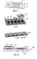
FIGS. 10 and11 , asassembly 200 is shown, which includesmanifold base 100, sample orslide holder frame 102, and cover 101. In certain embodiments, themanifold base 100 is in communication with a driving force (not shown), such as a vacuum, to drive fluid through one ormore slide holders 30 mounted on aslide holder frame 102 positioned on themanifold base 100, which can serve as a wash basin for multiple rinses, washes, etc. of the sample. In certain embodiments, one ormore covers 101 can be positioned over the one ormore slide holders 30 to prevent light from affecting any fluorescent signal chemistries involved in the assay and eliminating potential contamination of samples. In certain embodiments, themanifold base 100 can accommodate one or more slide holder frames 102. Each slide holder frame (102) can hold, for example, 1 - 12slide holders 30 in communication with the driving force. Theslide holder frame 102 can be removable from themanifold base 100. - In certain embodiments, cover 101 can include a
pinch handle 112 to assist in liftingcover 101 off theslide holder frame 102. In certain embodiments, thecover 101 can include atask tracker 103 to track which step in the protocol is in process, which is useful when multiple slide holder frames 102 are being used simultaneously, or are residing in an incubation chamber or refrigerator. In certain embodiments, thetask tracker 103 is a movable dial (with respect to the cover surface) with one or more stationary markings that point to other markings on thecover 101. In certain embodiments, thecover 101 may also have a plurality of spaced stackingindents 104 each configured to receive a respective leg 114 (FIG. 11 ) of anotherslide holder frame 102 to enable stacking for economy of space such as may be necessary when placed in an incubation chamber. - In certain embodiments, the
slide holder frame 102 includes a plurality of ports 105 (FIG. 12 ), each configured to receive arespective slide holder 30. The ports can be numbered as shown for facilitating the tracking of each individual assay. In the embodiment shown, eachslide holder frame 102 is configured to hold up to 12slide holders 30 along with 12 port plugs 106, although those skilled in the art will appreciate that fewer or more could be used. If aport 105 is not occupied by aslide holder 30, aport plug 106 can be installed to retain vacuum in the system. Whenports 105 are in use (e.g., are occupied by a slide holder 30), theplug 106 for thatport 105 can be stored in aconvenient storage aperture 148 next to the installedslide holder 30. In certain embodiments, theslide holder frame 102 can include a well 107 for storage of the slideholder assembly fixture 20. Activation of the driving force such as vacuum allows for simultaneous fluid flushing ofmultiple slide holders 30 positioned in theslide holder frame 102. -
FIG. 11 illustrates certain embodiments of theslide holder 30 positioned in theslide holder frame 102. In accordance with certain embodiments, spacedtabs 48 on the bottom of theslide holder 30 are received by correspondingslots 149 in theslide holder frame 102. Whenslide holder 30 is so positioned in theslide holder frame 102, thedrain 42 penetrates intoport 105 and is sealed byport seal 108. Avalve 110, such as a duckbill valve, is positioned in theport 105 and prevents fluid from exiting theslide holder chamber 33 until the valve is overcome by the application of vacuum to theport 105. - In certain embodiments, blocking, rinsing and washing steps are achieved by loading up the
reservoir 31 such as with a repeating pipette, squirt bottle or any dispensing device. A solution is loaded and flows into thesample chamber 33 and is allowed to soak the sample. The vacuum is activated and the solution flows over the sample and out thedrain 42, rinsing off any residual blocker, antibodies, linkers, reporters, chromogens or hemotoxilins, for example. - In certain embodiments, slide 10 supporting tissue sample 11 is placed in the slide
holder assembly fixture 20 with the tissue side facing upwardly. Theslide 10 is placed to ensure that the region containing the tissue is within the target area so as to not interfere with the gasket seal of theslide holder 30, as aided byindicators 12. Theslide holder 30 is then aligned onto the slideholder assembly fixture 20 and pressed firmly onto theslide 10 until the compression clips 43 engage in the respective cut-outs 28. - This assembly is next plugged into a desired port inserted into the
slide holder frame 102 on thebase 100. The sample port position can be recorded if needed. Any unused ports in theframe 102 are plugged with aport plug 106 as necessary. In certain embodiments, the plane of the slide is thus perpendicular to the plane of the surface of theslide holder frame 102; it is positioned in a horizontal/vertical plane to allow view of sample and slide information, and minimize fluid chamber volume. - If hydration or washing is necessary, the desired solution is introduced into the
reservoir 31 such as to hydrate or wash the tissue sample, for a desired time period. Vacuum can then be applied to the base to wash and flush the solution from the slide holder. - Blocking can be carried out by loading the desired concentration of a blocking agent into the injection/
recovery port 38 or thereservoir 31 of thesample chamber 33. Enough blocking solutions should be loaded to cover the sample 11 in thesample chamber 33. - Once all of the slide holders are filled, and if incubation is needed, the slide holder frame is covered with
cover 101, and thetask tracker 103 can be set to the appropriate task, such as the "blocker" indication. The coveredframe 102 may then be incubated, such as at room temperature, in an incubator, or in a refrigerator for the desired time. - After incubation, the blocking agent can be flushed by returning the
frame 102 to thebase 100, removing the cover, and applying vacuum, and any necessary wash steps carried out by introducing wash solution to thereservoir 31, allowing the sample 11 to soak (if needed) in the wash solution for the desired time, and then flushing by applying vacuum. A plurality of such wash steps can be employed if desired. - Primary antibody of the desired concentration can be introduced into the injection/
recovery port 38 in an amount sufficient to cover the sample 11. If an incubation step is desired, theframe 102 is covered withcover 101, and the task tracker set to the appropriate indication, such as "primary". The coveredframe 102 may then be incubated, such as at room temperature, in an incubator, or in a refrigerator, for the desired time. - After incubation, the
frame 102 is placed back on thebase 100, the cover removed, and flushed using vacuum. Alternatively, primary antibody can be recovered by extracting it fromsample chamber 33 viaport 38, such as with a pipette. Any desired wash steps carried out by introducing wash solution to thereservoir 31, allowing the sample 11 to soak (if needed) in the wash solution for the desired time, and then flushing by applying vacuum. A plurality of such wash steps can be employed if desired. - Linker or secondary antibody of the desired concentration can be introduced into the injection/
recovery port 38 in an amount sufficient to cover the sample 11. If an incubation step is desired, theframe 102 is covered withcover 101, and the task tracker set to the appropriate indication, such as "linker". The coveredframe 102 may then be incubated, such as at room temperature, in an incubator, or in a refrigerator for the desired time. - After incubation, the
frame 102 is placed back on thebase 100. Any desired wash steps may be carried out by removing the cover, introducing wash solution to thereservoir 31, allowing the sample 11 to soak (if needed) in the wash solution for the desired time, and then flushing by applying vacuum. A plurality of such wash steps can be employed if desired. - Reporter or tertiary antibody of the desired concentration can be introduced into the injection/
recovery port 38 in an amount sufficient to cover the sample 11. If an incubation step is desired, theframe 102 is covered withcover 101, and the task tracker set to the appropriate indication, such as "reporter". The coveredframe 102 may then be incubated, such as at room temperature, in an incubator, or in a refrigerator for the desired time. - After incubation, the
frame 102 is placed back on thebase 100. Any desired wash steps may be carried out by removing the cover, introducing wash solution to thereservoir 31, allowing the sample 11 to soak (if needed) in the wash solution for the desired time, and then flushing by applying vacuum. A plurality of such wash steps can be employed if desired. - Chromogen can be introduced into the injection/
recovery port 38 in an amount sufficient to cover the sample 11. If an incubation step is desired, theframe 102 is covered withcover 101, and the task tracker set to the appropriate indication, such as "chromogen". The coveredframe 102 may then be incubated, such as at room temperature, in an incubator, or in a refrigerator for the desired time. - After incubation, the
frame 102 is placed back on thebase 100. Any desired wash steps can be carried out by removing the cover, introducing wash solution to thereservoir 31, allowing the sample 11 to soak (if needed) in the wash solution for the desired time, and then flushing by applying vacuum. A plurality of such wash steps can be employed if desired. - Upon completion of the chromogen step, a final wash can be carried out before the slide holders are removed from the
slide holder frame 102. Removal of theslide 10 from theslide holder 30 can be carried out by bending away the bottom twocompression clips 43 such as by inserting them intoslots 66 in the slide holder assembly fixture 20 (FIG. 13 ), thereby releasing theslide 10. Theslide holder 30 can be discarded. -
FIG. 14 illustrates another embodiment of a slide 10'. In the embodiment shown, the slide 10' can be a molded or a diecut slide with aporous membrane 201 attached to it. The membrane can be attached to the slide by any suitable means, such as by heat sealing, ultrasonic welding, or with a suitable adhesive, such as silicone-based adhesive or an acrylic adhesive. A wide variety of membranes made from a wide variety of materials may be used in the embodiments described herein. Examples of such materials include polysaccharides, synthetic and semi-synthetic polymers, metals, metal oxides, ceramics, glass, and combinations thereof. Exemplary polymers that can be used to manufacture the membranes that may be used include, but are not limited to, substituted or unsubstituted polyacrylamides, polystyrenes, polymethacrylamides, polyimides, polyacrylates, polycarbonates, polymethacrylates, polyvinyl hydrophilic polymers, polystyrenes, polysulfones, polyethersulfones, copolymers or styrene and divinylbenzene, aromatic polysulfones, polytetrafluoroethylenes (PTFE), perfluorinated thermoplastic polymers, polyolefins, aromatic polyamides, aliphatic polyamides, ultrahigh molecular weight polyethylenes, polyvinylidene difluoride (PVDF), polyetheretherketones (PEEK), polyesters, and combinations thereof. Exemplary commercially available membranes are Durapore® and Millipore Express® and Millipore Express PLUS® available from EMD Millipore Corp. (Billerica, MA). Preferably the membranes are microporous membranes. -
Sample sections 301 such as tissue sections are mounted to themembrane 201. Themembrane 201 acts as a sample support, allowing blocking and antibody fluids, for example, to interact with the sample, but also allows for fluid transfer through themembrane 201 during rinsing and washing steps, for example. - As shown in
FIGS. 15A, 15B and 15C , each slide 10' can be positioned directly into a corresponding slide well 302 in a vacuummanifold slide frame 205. The vacuummanifold slide frame 205 may have one ormore slide wells 302. In certain embodiments, each slide well 302 has agasket 401 such as a silicone orfoam sealing gasket 401 to seal each slide 10' in a respective slide well 302. Upon application of vacuum as the driving force, fluid transfers through themembrane 301 and through aporous surface underdrain 501 beneath (in the direction of fluid flow) themembrane 201. In certain embodiments, the underdrain includes molded drain slots, holes, sintered porous material, etc. that support the membrane due to membrane sagging. Preferably the underdrain is easy to clean but moldable and provides a vacuum driven draining from below. -
FIGS. 16A-16C illustrate an alternative embodiment of a slide holder 30'. Likeslide holder 30, slide holder 30' is a single use device and includes a reservoir 31' and drainports 41', 41" that respectively drain fluid from each chamber intodrains 42', 42". Unlikeslide holder 30, slide holder 30' includesmultiple sample chambers 33' and 33" (two shown), each in fluid communication with the reservoir 31' via narrow slit 32' at the bottom of the reservoir 31'. In certain embodiments, thechambers 33' and 33" are opposed to one another and coextensive, but are in fluid isolation from one another so that each sample in a respective chamber is acted on independently of the other. In certain embodiments, eachsample chamber 33', 33" includes arespective gasket 35', 35", such as a dispensed silicon gasket, as seen inFIGS. 16B and 16C . In certain embodiments, thegaskets 35', 35" also could be overmolded, such as overmolded thermoplastic elastomer (TPE), overmolded silicone, diecut silicone, diecut double stick foam, thick diecut acrylic adhesive, etc. Eachgasket 35', 35" includes a region that delimits a respective injection/recoveryport fluid channel 36', 36". Each injection/recoveryport fluid channel 36', 36" is in fluid communication with a respective injection/recoveryport channel port 37', 37", which in turn is in fluid communication with a respective injection/recovery port 38', 38" configured to receive an injecting device such as a pipette. Each injection/recoveryport fluid channel 36', 36" opens into arespective sample chamber 33', 33" atrespective outlet openings 40', 40". - In certain embodiments, the
slides 10', 10" are attached to the slide holder 30' in a manner similar to the above embodiment where only one slide and sample chamber is present. Suitable fluids can be introduced into the sample chamber 33', such as via pipette or by the reservoir 31'. For example, the tips of respective pipettes can be inserted into the injection/recovery ports 38', 38". Fluid from each pipette flows into the respective injection/recoveryport fluid channel 36', 36",respective outlet openings 40', 40" and intorespective sample chambers 33', 33", where it contacts the samples. -
FIGS. 17A-17C illustrate a horizontal embodiment where a tissue mountedsubstrate 10 such as a standard glass slide is constrained within a thermoformed slideholder flow cell 600 and sealed with asuitable adhesive 601, such as a semi-permanent fluid-proof adhesive, such as an acrylic or silicone-based adhesive. In certain embodiments, the thermoformed slideholder flow cell 600 has a plurality ofstandoffs 602 positioned in each of the four corners to allow a slight gap on the sides and underneath theslide 10 to allow for drainage. Theflow cell 600 includes an opentop member 622 that is hingedly connected to slideholder member 623. In certain embodiments, the hinge is a "living hinge" formed during the thermoforming process. Thetop member 622 is in the open position shown inFIG. 17A to load the slide into theflow cell 600, and is then pivoted into a closed position as shown inFIG. 17C . Various reagents, such as blocking agents, antibodies and stains can be placed onto the tissue on theslide 10, and rinse and soak solutions can be introduced from the reservoir opening on the top 622 (FIG. 17C ). -
FIGS. 18A-18C illustrate an embodiment of a manifold suitable for use with the thermoformed slideholder flow cell 600 shown inFIG. 17A . In certain embodiments,vacuum manifold frame 620 includes a plurality ofslide holder wells 632. Each well 632 is configured to receive a respective slideholder flow cell 600. In certain embodiments, each well 632 includes adrain port 624, which receives thedrain 603 of the slideholder flow cell 600 in sealing relation (627). In certain embodiments, adrain channel 626 is formed in themanifold frame 620 in communication with thedrain port 624. Upon the introduction of a driving force such as vacuum, fluid is flushed from the slide through themultiple bypasses 605, and down through thedrain 603 and then through thedrain channel 626. A valve, such as a duckbill valve, may be positioned in theport 624 and prevents fluid from exiting until the valve is overcome by the application of vacuum. -
FIG. 19 illustrates an embodiment where the adhesive 640 on the underside of the thermoformed slideholder flow cell 600 seals directly to theslide 10 surface. Asmall slit 645 in the adhesive 640 acts as a drain port. Soaking and rinsing fluids are introduced using thereservoir opening 630, allowing the flushing of compounds off the tissue section via vacuum on a vacuum manifold. -
FIGS. 20A-20C illustrate a thermoform vertical embodiment. A standard tissue mountedglass slide 10 is constrained within a thermoformed slideholder flow cell 200, sealed with a semi-permanent fluid-proof adhesive 260, such as a silicone-based adhesive or acrylic adhesive. In certain embodiments, the thermoform hasstandoffs 400 in all four corners to allow a slight gap on the tissue side of theslide 10. A plurality of spacedlongitudinal ribs 411 can be provided to provide added rigidity to theflow cell 200, and to provide a gap allowing proper drainage upon application of a driving force. When assembled, thethermoform 200 creates a gap in front of the tissue that allows reagents such as blocking agents, antibodies, stains, etc. to be in contact with the tissue, although rinse and soak solutions, for example, can be introduced from thereservoir 203 opening on the top. When a driving force such as vacuum is applied, the fluid is flushed from the slide through the capillary drain (e.g., a small slit) 500 in the adhesive, and down through a drain. In certain embodiments, the thermoform is formed from afirst member 401 pivotally connected to asecond member 402 by ahinge 403 to allow for quick assembly. Although in the embodiment shown thehinge 403 is shown along the longitudinal axis of the flow cell, in certain embodiments the hinge could be oriented at the base of the flow cell. - As shown in
FIGS. 21 and22 , the tip of apipette 39 may introduce fluids such as antibodies and wash fluids, into thereservoir 203, thereservoir 203 being in fluid communication with thetissue chamber 204 that includes a known region for the fluids. Theflow cell 200 is shown positioned in a vacuum manifold sealing assembly. In certain embodiments, the vacuum manifold 100' includes one or more flow cell receiving wells 149' that can includesilicone tubing tubes capillary drain 500 in the adhesive layer created by the sandwich of the thermoform and the adhesive, as illustrated by the dottedarrow 510 inFIGS. 21 and22 .
Claims (18)
- A sample holder, comprising:a fluid reservoir in communication with a sample chamber;a first port in fluid communication with said sample chamber via a fluid channel;a second port in fluid communication with said sample chamber; anda plurality of spaced clips configured to receive a sample substrate, wherein when said sample substrate is engaged in said sample holder, sample supported by said sample substrate is in said sample chamber.
- The sample holder of claim 1, wherein said fluid channel is defined by a gasket.
- The sample holder of claim 1, wherein said first port is configured to receive a pipette.
- The sample holder of claim 1, wherein said sample substrate comprises a slide.
- The sample holder of claim 1, wherein said first port is an injection or recovery port, and said second port is a drain port.
- A method of attaching a sample substrate to a sample holder, comprising:providing a sample holder having a fluid reservoir in communication with a sample chamber, a first port in fluid communication with said sample chamber via a fluid channel, a second port in fluid communication with said sample chamber, and a plurality of spaced clips configured to receive a sample substrate;providing a sample substrate having a sample thereon;providing a sample substrate assembly fixture having one or more perimeter walls for containing said sample substrate;engaging said sample substrate in said sample substrate assembly fixture;engaging said sample substrate assembly fixture such that said sample on said sample substrate is positioned in said sample chamber.
- The method of claim 6, wherein said sample substrate comprises a slide.
- The method of claim 6, further comprising providing fluid level indicators on said sample substrate assembly fixture to assist in placement of said sample on said sample substrate.
- A sample holder frame comprising a surface having a plurality of ports, each port configured to receive a respective sample holder having a sample chamber, a fluid reservoir in communication with said sample chamber, a first port in fluid communication with said sample chamber via a fluid channel, and a second port in fluid communication with said sample chamber; wherein when a sample holder is positioned in a respective port, the drain of said sample holder penetrates into said respective port.
- The sample holder frame of claim 9, wherein a valve is associated with each said port.
- The sample holder frame of claim 9, wherein said sample holder comprises a sample substrate, and wherein when said sample holder is positioned in a port, the plane of said sample substrate is perpendicular to the plane of said surface of said sample holder frame.
- The sample holder frame of claim 9, further comprising a task tracker.
- The sample holder of any of claims 1 to 5, wherein:the sample chamber with which the fluid reservoir is in communication is a first sample chamber and the fluid reservoir is further in communication with a second sample chamber;the fluid channel via which the first port is in fluid communication with said first sample chamber is a first fluid channel;the plurality of spaced clips configured to receive a sample substrate is a first plurality of spaced clips configured to receive a first sample substrate, wherein when said first sample substrate is engaged in said sample holder, sample supported by said first sample substrate is in said first sample chamber; andwherein the sample holder further comprises:a third port in fluid communication with said second sample chamber via a second fluid channel; anda second plurality of spaced clips configured to receive a second sample substrate, wherein when said second sample substrate is engaged in said sample holder, sample supported by said second sample substrate is in said second sample chamber.
- The sample holder of claim 13, wherein said first fluid channel is defined by a first gasket, and said second fluid channel is defined by a second gasket.
- The sample holder of claim 13, wherein said first and second sample substrates each comprises a slide.
- A flow cell comprising an open top member hingedly connected to slide holder member, said open top member pivoting between an open position allowing access to load a slide into said slide holder member, and a closed position, and an adhesive sealing said top member to said slide holder member when said slide is positioned on said slide holder member.
- An assembly comprising the flow cell of claim 16 and a vacuum manifold having a well for receiving said flow cell in sealing relation.
- A slide having an attached membrane, said slide being positioned directly in a slide well of a vacuum manifold.
Applications Claiming Priority (2)
| Application Number | Priority Date | Filing Date | Title |
|---|---|---|---|
| US201461951135P | 2014-03-11 | 2014-03-11 | |
| US201462039082P | 2014-08-19 | 2014-08-19 |
Publications (3)
| Publication Number | Publication Date |
|---|---|
| EP2918343A2 true EP2918343A2 (en) | 2015-09-16 |
| EP2918343A3 EP2918343A3 (en) | 2016-03-02 |
| EP2918343B1 EP2918343B1 (en) | 2023-09-13 |
Family
ID=52684013
Family Applications (1)
| Application Number | Title | Priority Date | Filing Date |
|---|---|---|---|
| EP15158134.5A Active EP2918343B1 (en) | 2014-03-11 | 2015-03-09 | Disposable IHC sample holder with fluid exchange, system and method for use. |
Country Status (6)
| Country | Link |
|---|---|
| US (1) | US10634590B2 (en) |
| EP (1) | EP2918343B1 (en) |
| JP (3) | JP6258242B2 (en) |
| CN (2) | CN104965071B (en) |
| ES (1) | ES2959532T3 (en) |
| SG (1) | SG10201501126YA (en) |
Cited By (4)
| Publication number | Priority date | Publication date | Assignee | Title |
|---|---|---|---|---|
| CN109292268A (en) * | 2018-12-03 | 2019-02-01 | 兰州大学 | A kind of pathology department sample infuser device and its application method |
| US10596574B2 (en) | 2015-04-24 | 2020-03-24 | Euroimmun Medizinische Labordiagnostika Ag | Incubation tray |
| WO2020131070A1 (en) * | 2018-12-20 | 2020-06-25 | Tecan Trading Ag | Method of treating a sample |
| EP3799106A1 (en) * | 2019-09-30 | 2021-03-31 | Jeol Ltd. | Sample attachment device |
Families Citing this family (6)
| Publication number | Priority date | Publication date | Assignee | Title |
|---|---|---|---|---|
| DK3372313T3 (en) * | 2017-03-07 | 2020-08-24 | Dreampath Diagnostics | TRAY FOR STORING SAMPLE PLATES, CABINET FOR STORING SAME AND DEVICE FOR IDENTIFYING SAID PLATES |
| USD945010S1 (en) * | 2018-03-15 | 2022-03-01 | Leica Biosystems Nussloch Gmbh | Holder for coverslips or specimen slides |
| KR20210104648A (en) * | 2018-12-20 | 2021-08-25 | 라이카 바이오시스템즈 멜버른 피티와이 엘티디 | slide output module |
| EP3841386A4 (en) * | 2018-12-20 | 2021-10-20 | Leica Biosystems Melbourne Pty Ltd | A slide tray assembly |
| US11061045B2 (en) | 2019-03-12 | 2021-07-13 | Picodya Technologies Ltd. | Sample analysis system and method |
| CN211235173U (en) * | 2019-11-26 | 2020-08-11 | 莱卡生物系统努斯洛赫有限责任公司 | Tissue treatment equipment |
Family Cites Families (59)
| Publication number | Priority date | Publication date | Assignee | Title |
|---|---|---|---|---|
| US5002736A (en) | 1987-03-31 | 1991-03-26 | Fisher Scientific Co. | Microscope slide and slide assembly |
| GB8722902D0 (en) | 1987-09-30 | 1987-11-04 | Shandon Southern Prod | Tissue &c processing |
| JPH01126474U (en) | 1988-02-22 | 1989-08-29 | ||
| US4873126A (en) | 1988-08-15 | 1989-10-10 | Becton, Dickinson And Company | System and process for spotting reagents on porous supports |
| WO1991013335A1 (en) | 1990-03-02 | 1991-09-05 | Ventana Medical Systems | Automated biological reaction apparatus |
| US5192503A (en) | 1990-05-23 | 1993-03-09 | Mcgrath Charles M | Probe clip in situ assay apparatus |
| DE69527585T2 (en) * | 1994-06-08 | 2003-04-03 | Affymetrix Inc | Method and device for packaging chips |
| EP0729021A1 (en) | 1995-02-25 | 1996-08-28 | Roche Diagnostics GmbH | Device for treating samples on microscope slides |
| GB9506312D0 (en) * | 1995-03-28 | 1995-05-17 | Medical Res Council | Improvements in or relating to sample processing |
| AUPN923596A0 (en) | 1996-04-12 | 1996-05-09 | Australian Biomedical Corporation Limited | Method and apparatus for treatment of human or animal cell samples |
| GB9710773D0 (en) | 1997-05-23 | 1997-07-23 | Life Sciences Int Europe | Cytofunnel arrangement |
| CA2315809C (en) * | 1997-12-23 | 2014-06-03 | Dako A/S | Cartridge device for processing a sample mounted on a surface of a support member |
| US6096271A (en) | 1998-02-27 | 2000-08-01 | Cytologix Corporation | Random access slide stainer with liquid waste segregation |
| US6183693B1 (en) | 1998-02-27 | 2001-02-06 | Cytologix Corporation | Random access slide stainer with independent slide heating regulation |
| US6673620B1 (en) | 1999-04-20 | 2004-01-06 | Cytologix Corporation | Fluid exchange in a chamber on a microscope slide |
| CA2374423C (en) | 1999-05-28 | 2013-04-09 | Cepheid | Apparatus and method for analyzing a liquid sample |
| DE19941905C2 (en) | 1999-09-02 | 2002-06-06 | Max Planck Gesellschaft | Sample chamber for the liquid treatment of biological samples |
| US6358473B1 (en) | 1999-10-05 | 2002-03-19 | Albert Coello | Microscope slide heater |
| DE10002920A1 (en) * | 2000-01-19 | 2001-07-26 | Epigenomics Ag | Device for contacting biological material immobilized on surface with solution of second biological material, especially hybridization of DNA samples, comprises a cavity receiving solution with cover which has seal around its edges |
| EP1284823A1 (en) | 2000-03-16 | 2003-02-26 | Biogenex Laboratories | Automated specimen processing apparatus with fluid detection |
| CA2453323A1 (en) | 2001-07-18 | 2003-01-30 | Irm, Llc | High throughput incubation devices |
| DE10144989B4 (en) | 2001-09-12 | 2007-11-08 | Leica Microsystems Nussloch Gmbh | System for dyeing and covering slides |
| EP1494808B1 (en) | 2002-04-15 | 2013-07-03 | Ventana Medical Systems, Inc. | Automated high volume slide staining system |
| AUPS311402A0 (en) | 2002-06-20 | 2002-07-18 | Vision Biosystems Limited | A method and apparatus for providing a reaction chamber |
| DK2322938T3 (en) | 2002-09-26 | 2013-04-08 | Biopath Automation Llc | Apparatus and method for automatic handling and embedding of tissue samples |
| EP1545775B1 (en) | 2002-09-26 | 2010-06-16 | BioPath Automation, L.L.C. | Cassette and embedding assembly, staging devices, and methods for handling tissue samples |
| GB0301047D0 (en) | 2003-01-16 | 2003-02-19 | Thermo Shandon Ltd | A centrifugation device |
| US20050074890A1 (en) | 2003-05-19 | 2005-04-07 | Ventana Medical Systems, Inc. | Electrophoretic in situ tissue staining |
| US7767152B2 (en) | 2003-08-11 | 2010-08-03 | Sakura Finetek U.S.A., Inc. | Reagent container and slide reaction retaining tray, and method of operation |
| US7744817B2 (en) * | 2003-08-11 | 2010-06-29 | Sakura Finetek U.S.A., Inc. | Manifold assembly |
| AU2004271210A1 (en) | 2003-09-09 | 2005-03-17 | Biogenex Laboratories | Sample processing system |
| US7682833B2 (en) | 2003-09-10 | 2010-03-23 | Abbott Point Of Care Inc. | Immunoassay device with improved sample closure |
| CN1898022B (en) | 2003-10-17 | 2011-04-06 | 比欧帕斯自动化公司 | Cassette for handling and holding tissue samples during processing, embedding and microtome procedures, and methods therefor |
| JP4949038B2 (en) | 2003-12-01 | 2012-06-06 | ダコ デンマーク アクティーゼルスカブ | Methods and compositions for immunohistochemical detection |
| EP1697719B1 (en) | 2003-12-23 | 2018-09-19 | Ventana Medical Systems, Inc. | Method and apparatus for efficient thin film fluid processing of flat surfaces |
| EP1771730B1 (en) | 2004-07-23 | 2014-08-20 | Ventana Medical Systems, Inc. | Method and apparatus for applying fluids to a biological sample |
| CA2623241A1 (en) | 2005-04-21 | 2006-11-02 | Celerus Diagnostics, Inc. | Parallel processing fluidic method and apparatus for automated rapid immunohistochemistry |
| WO2006127852A2 (en) | 2005-05-24 | 2006-11-30 | Angros Lee H | In situ heat induced antigen recovery and staining apparatus and method |
| US8652421B2 (en) | 2005-11-03 | 2014-02-18 | Emd Millipore Corporation | Immunoassay product and process |
| US20080081368A1 (en) | 2006-10-03 | 2008-04-03 | Anne Marie Bailey | Method and apparatus that increases efficiency and reproducibility in immunohistochemistry and immunocytochemistry |
| WO2009014769A1 (en) | 2007-07-26 | 2009-01-29 | Nypro Inc. | Methods and apparatus for supporting a vacuum filtration device |
| US8231012B2 (en) | 2007-07-26 | 2012-07-31 | Roush Life Sciences, Llc | Filtrate storage system |
| ES2837748T3 (en) | 2007-10-23 | 2021-07-01 | Becton Dickinson Co | Multi-chamber tissue containment system for molecular and histological diagnosis |
| ES2553190T3 (en) | 2007-12-10 | 2015-12-04 | Dako Denmark A/S | Tissue processing apparatus |
| WO2009085842A1 (en) | 2007-12-21 | 2009-07-09 | Ventana Medical Systems, Inc. | Relative-translational liquid application and removal |
| US8169006B2 (en) | 2008-11-29 | 2012-05-01 | Electronics And Telecommunications Research Institute | Bio-sensor chip for detecting target material |
| WO2010077975A1 (en) | 2008-12-17 | 2010-07-08 | Ventana Medical Systems, Inc. | Apparatus for sealing slide bottom |
| WO2010075568A2 (en) | 2008-12-24 | 2010-07-01 | Life Technologies Corporation | Biological analysis systems, devices and methods |
| WO2011002779A2 (en) | 2009-06-30 | 2011-01-06 | Ventana Medical Systems, Inc. | Methods and apparatuses for applying and removing fluids for processing biological samples |
| US8524507B2 (en) | 2009-08-19 | 2013-09-03 | The Cleveland Clinic Foundation | Method for detecting a target molecule in a biological sample |
| US8877485B2 (en) | 2009-12-09 | 2014-11-04 | Dako Denmark A/S | Apparatus and method for processing biological samples |
| US8765476B2 (en) | 2009-12-22 | 2014-07-01 | Biocare Medical, Llc | Methods and systems for efficient automatic slide staining in immunohistochemistry sample processing |
| JP5491228B2 (en) * | 2010-02-16 | 2014-05-14 | 御木本製薬株式会社 | Staining solution and staining method |
| DK2625502T3 (en) | 2010-10-06 | 2018-12-17 | Biocare Medical Llc | Method and system for efficient processing of biological samples |
| US9157838B2 (en) | 2010-12-23 | 2015-10-13 | Emd Millipore Corporation | Chromatography apparatus and method |
| US9272279B2 (en) | 2011-05-11 | 2016-03-01 | Emd Millipore Corporation | Immunoassay product and process |
| DE102011110250B4 (en) | 2011-05-13 | 2019-05-16 | Leica Biosystems Nussloch Gmbh | Gripping device for transporting racks |
| US8932543B2 (en) | 2011-09-21 | 2015-01-13 | Sakura Finetek U.S.A., Inc. | Automated staining system and reaction chamber |
| EP2802417B1 (en) | 2012-01-09 | 2019-05-15 | Micronics, Inc. | Microfluidic reactor system |
-
2015
- 2015-02-10 US US14/618,007 patent/US10634590B2/en active Active
- 2015-02-13 SG SG10201501126YA patent/SG10201501126YA/en unknown
- 2015-03-09 ES ES15158134T patent/ES2959532T3/en active Active
- 2015-03-09 EP EP15158134.5A patent/EP2918343B1/en active Active
- 2015-03-10 JP JP2015047269A patent/JP6258242B2/en active Active
- 2015-03-11 CN CN201510105679.5A patent/CN104965071B/en active Active
- 2015-03-11 CN CN201710347684.6A patent/CN107356738B/en active Active
-
2017
- 2017-12-04 JP JP2017232934A patent/JP6599962B2/en active Active
-
2019
- 2019-10-03 JP JP2019183209A patent/JP6891243B2/en active Active
Non-Patent Citations (1)
| Title |
|---|
| None |
Cited By (4)
| Publication number | Priority date | Publication date | Assignee | Title |
|---|---|---|---|---|
| US10596574B2 (en) | 2015-04-24 | 2020-03-24 | Euroimmun Medizinische Labordiagnostika Ag | Incubation tray |
| CN109292268A (en) * | 2018-12-03 | 2019-02-01 | 兰州大学 | A kind of pathology department sample infuser device and its application method |
| WO2020131070A1 (en) * | 2018-12-20 | 2020-06-25 | Tecan Trading Ag | Method of treating a sample |
| EP3799106A1 (en) * | 2019-09-30 | 2021-03-31 | Jeol Ltd. | Sample attachment device |
Also Published As
| Publication number | Publication date |
|---|---|
| JP2015172578A (en) | 2015-10-01 |
| CN107356738A (en) | 2017-11-17 |
| EP2918343B1 (en) | 2023-09-13 |
| US10634590B2 (en) | 2020-04-28 |
| US20150260621A1 (en) | 2015-09-17 |
| SG10201501126YA (en) | 2015-10-29 |
| ES2959532T3 (en) | 2024-02-26 |
| JP6891243B2 (en) | 2021-06-18 |
| CN104965071B (en) | 2017-05-10 |
| EP2918343A3 (en) | 2016-03-02 |
| CN104965071A (en) | 2015-10-07 |
| CN107356738B (en) | 2019-07-05 |
| JP2018054630A (en) | 2018-04-05 |
| JP6258242B2 (en) | 2018-01-10 |
| JP2020020806A (en) | 2020-02-06 |
| JP6599962B2 (en) | 2019-10-30 |
Similar Documents
| Publication | Publication Date | Title |
|---|---|---|
| US10634590B2 (en) | IHC, tissue slide fluid exchange disposable and system | |
| JP6666313B2 (en) | Connectors for pneumatic devices in microfluidic systems | |
| EP1487580B1 (en) | Hybridization device | |
| EP2794107B1 (en) | Sequential lateral flow capillary device for analyte determination | |
| EP1171761B8 (en) | Fluid exchange in a chamber on a microscope slide | |
| JP2007163465A (en) | Product for immunoassay, and process therefor | |
| AU2003217261A1 (en) | Hybridization device and method | |
| US20200298241A1 (en) | Slide chamber | |
| US20040001779A1 (en) | Biochip holder and method of collecting fluid | |
| JP6723541B2 (en) | Imaging microfluidic flow cell assembly and method of use thereof | |
| CA2454915C (en) | Fixtures for use in parallel processing bio-chips | |
| CN110252432B (en) | Culture tank and culture tray with multiple culture tanks | |
| WO2015175189A1 (en) | Microfluidic flow cell assemblies and method of use | |
| EP3377223A1 (en) | Cover with micro-container interface for covering a microfluidic gap | |
| JP2004264301A (en) | Apparatus for immunologically labelling cross section of thin tissue and method for using it | |
| US20160082437A1 (en) | Cover with micro-container interface for covering a microfluidic gap | |
| WO2021259497A1 (en) | Microfluidic chip and pumping device | |
| AU2007202887A1 (en) | Hybridization device and method |
Legal Events
| Date | Code | Title | Description |
|---|---|---|---|
| PUAI | Public reference made under article 153(3) epc to a published international application that has entered the european phase |
Free format text: ORIGINAL CODE: 0009012 |
|
| AK | Designated contracting states |
Kind code of ref document: A2 Designated state(s): AL AT BE BG CH CY CZ DE DK EE ES FI FR GB GR HR HU IE IS IT LI LT LU LV MC MK MT NL NO PL PT RO RS SE SI SK SM TR |
|
| AX | Request for extension of the european patent |
Extension state: BA ME |
|
| PUAL | Search report despatched |
Free format text: ORIGINAL CODE: 0009013 |
|
| AK | Designated contracting states |
Kind code of ref document: A3 Designated state(s): AL AT BE BG CH CY CZ DE DK EE ES FI FR GB GR HR HU IE IS IT LI LT LU LV MC MK MT NL NO PL PT RO RS SE SI SK SM TR |
|
| AX | Request for extension of the european patent |
Extension state: BA ME |
|
| RIC1 | Information provided on ipc code assigned before grant |
Ipc: B01L 3/00 20060101AFI20160122BHEP Ipc: G01N 1/31 20060101ALI20160122BHEP Ipc: B01L 9/00 20060101ALI20160122BHEP |
|
| 17P | Request for examination filed |
Effective date: 20160902 |
|
| RBV | Designated contracting states (corrected) |
Designated state(s): AL AT BE BG CH CY CZ DE DK EE ES FI FR GB GR HR HU IE IS IT LI LT LU LV MC MK MT NL NO PL PT RO RS SE SI SK SM TR |
|
| STAA | Information on the status of an ep patent application or granted ep patent |
Free format text: STATUS: REQUEST FOR EXAMINATION WAS MADE |
|
| R17P | Request for examination filed (corrected) |
Effective date: 20160902 |
|
| STAA | Information on the status of an ep patent application or granted ep patent |
Free format text: STATUS: EXAMINATION IS IN PROGRESS |
|
| 17Q | First examination report despatched |
Effective date: 20170919 |
|
| RAP1 | Party data changed (applicant data changed or rights of an application transferred) |
Owner name: EMD MILLIPORE CORPORATION |
|
| STAA | Information on the status of an ep patent application or granted ep patent |
Free format text: STATUS: EXAMINATION IS IN PROGRESS |
|
| STAA | Information on the status of an ep patent application or granted ep patent |
Free format text: STATUS: EXAMINATION IS IN PROGRESS |
|
| GRAP | Despatch of communication of intention to grant a patent |
Free format text: ORIGINAL CODE: EPIDOSNIGR1 |
|
| STAA | Information on the status of an ep patent application or granted ep patent |
Free format text: STATUS: GRANT OF PATENT IS INTENDED |
|
| INTG | Intention to grant announced |
Effective date: 20230317 |
|
| GRAS | Grant fee paid |
Free format text: ORIGINAL CODE: EPIDOSNIGR3 |
|
| P01 | Opt-out of the competence of the unified patent court (upc) registered |
Effective date: 20230602 |
|
| GRAA | (expected) grant |
Free format text: ORIGINAL CODE: 0009210 |
|
| STAA | Information on the status of an ep patent application or granted ep patent |
Free format text: STATUS: THE PATENT HAS BEEN GRANTED |
|
| RIN1 | Information on inventor provided before grant (corrected) |
Inventor name: EMERICK, MARC Inventor name: GUTIERREZ, SARA D. Inventor name: KELLARD, LIBBY Inventor name: AMARA, RYAN A. Inventor name: DOYLE, JOHN Inventor name: SYDLOWSKI, PAUL Inventor name: SCOTT, CHRIS |
|
| RIN1 | Information on inventor provided before grant (corrected) |
Inventor name: GUTIERREZ, SARA D. Inventor name: KELLARD, LIBBY Inventor name: AMARA, RYAN A. Inventor name: DOYLE, JOHN Inventor name: SYDLOWSKI, PAUL Inventor name: SCOTT, CHRIS Inventor name: EMERICK, MARC |
|
| AK | Designated contracting states |
Kind code of ref document: B1 Designated state(s): AL AT BE BG CH CY CZ DE DK EE ES FI FR GB GR HR HU IE IS IT LI LT LU LV MC MK MT NL NO PL PT RO RS SE SI SK SM TR |
|
| REG | Reference to a national code |
Ref country code: GB Ref legal event code: FG4D |
|
| REG | Reference to a national code |
Ref country code: CH Ref legal event code: EP |
|
| REG | Reference to a national code |
Ref country code: DE Ref legal event code: R096 Ref document number: 602015085663 Country of ref document: DE |
|
| REG | Reference to a national code |
Ref country code: NL Ref legal event code: FP Ref country code: IE Ref legal event code: FG4D |
|
| REG | Reference to a national code |
Ref country code: LT Ref legal event code: MG9D |
|
| PG25 | Lapsed in a contracting state [announced via postgrant information from national office to epo] |
Ref country code: GR Free format text: LAPSE BECAUSE OF FAILURE TO SUBMIT A TRANSLATION OF THE DESCRIPTION OR TO PAY THE FEE WITHIN THE PRESCRIBED TIME-LIMIT Effective date: 20231214 |
|
| PG25 | Lapsed in a contracting state [announced via postgrant information from national office to epo] |
Ref country code: SE Free format text: LAPSE BECAUSE OF FAILURE TO SUBMIT A TRANSLATION OF THE DESCRIPTION OR TO PAY THE FEE WITHIN THE PRESCRIBED TIME-LIMIT Effective date: 20230913 Ref country code: RS Free format text: LAPSE BECAUSE OF FAILURE TO SUBMIT A TRANSLATION OF THE DESCRIPTION OR TO PAY THE FEE WITHIN THE PRESCRIBED TIME-LIMIT Effective date: 20230913 Ref country code: NO Free format text: LAPSE BECAUSE OF FAILURE TO SUBMIT A TRANSLATION OF THE DESCRIPTION OR TO PAY THE FEE WITHIN THE PRESCRIBED TIME-LIMIT Effective date: 20231213 Ref country code: LV Free format text: LAPSE BECAUSE OF FAILURE TO SUBMIT A TRANSLATION OF THE DESCRIPTION OR TO PAY THE FEE WITHIN THE PRESCRIBED TIME-LIMIT Effective date: 20230913 Ref country code: LT Free format text: LAPSE BECAUSE OF FAILURE TO SUBMIT A TRANSLATION OF THE DESCRIPTION OR TO PAY THE FEE WITHIN THE PRESCRIBED TIME-LIMIT Effective date: 20230913 Ref country code: HR Free format text: LAPSE BECAUSE OF FAILURE TO SUBMIT A TRANSLATION OF THE DESCRIPTION OR TO PAY THE FEE WITHIN THE PRESCRIBED TIME-LIMIT Effective date: 20230913 Ref country code: GR Free format text: LAPSE BECAUSE OF FAILURE TO SUBMIT A TRANSLATION OF THE DESCRIPTION OR TO PAY THE FEE WITHIN THE PRESCRIBED TIME-LIMIT Effective date: 20231214 Ref country code: FI Free format text: LAPSE BECAUSE OF FAILURE TO SUBMIT A TRANSLATION OF THE DESCRIPTION OR TO PAY THE FEE WITHIN THE PRESCRIBED TIME-LIMIT Effective date: 20230913 |
|
| REG | Reference to a national code |
Ref country code: AT Ref legal event code: MK05 Ref document number: 1610717 Country of ref document: AT Kind code of ref document: T Effective date: 20230913 |
|
| REG | Reference to a national code |
Ref country code: ES Ref legal event code: FG2A Ref document number: 2959532 Country of ref document: ES Kind code of ref document: T3 Effective date: 20240226 |
|
| PGFP | Annual fee paid to national office [announced via postgrant information from national office to epo] |
Ref country code: NL Payment date: 20240108 Year of fee payment: 10 |
|
| PG25 | Lapsed in a contracting state [announced via postgrant information from national office to epo] |
Ref country code: IS Free format text: LAPSE BECAUSE OF FAILURE TO SUBMIT A TRANSLATION OF THE DESCRIPTION OR TO PAY THE FEE WITHIN THE PRESCRIBED TIME-LIMIT Effective date: 20240113 |
|
| PG25 | Lapsed in a contracting state [announced via postgrant information from national office to epo] |
Ref country code: AT Free format text: LAPSE BECAUSE OF FAILURE TO SUBMIT A TRANSLATION OF THE DESCRIPTION OR TO PAY THE FEE WITHIN THE PRESCRIBED TIME-LIMIT Effective date: 20230913 |