EP2918155A2 - Method and control unit for adjusting the operating width of a plough - Google Patents
Method and control unit for adjusting the operating width of a plough Download PDFInfo
- Publication number
- EP2918155A2 EP2918155A2 EP15401007.8A EP15401007A EP2918155A2 EP 2918155 A2 EP2918155 A2 EP 2918155A2 EP 15401007 A EP15401007 A EP 15401007A EP 2918155 A2 EP2918155 A2 EP 2918155A2
- Authority
- EP
- European Patent Office
- Prior art keywords
- plow
- section
- distance
- determined
- central point
- Prior art date
- Legal status (The legal status is an assumption and is not a legal conclusion. Google has not performed a legal analysis and makes no representation as to the accuracy of the status listed.)
- Granted
Links
- 238000000034 method Methods 0.000 title claims abstract description 41
- 238000004364 calculation method Methods 0.000 claims description 18
- 238000003780 insertion Methods 0.000 claims description 2
- 230000037431 insertion Effects 0.000 claims description 2
- 238000012545 processing Methods 0.000 description 7
- 239000013598 vector Substances 0.000 description 5
- 238000012937 correction Methods 0.000 description 4
- 238000013439 planning Methods 0.000 description 4
- 238000004422 calculation algorithm Methods 0.000 description 3
- 238000004590 computer program Methods 0.000 description 2
- 238000012913 prioritisation Methods 0.000 description 2
- 239000002689 soil Substances 0.000 description 2
- 238000007726 management method Methods 0.000 description 1
- 238000012544 monitoring process Methods 0.000 description 1
- 238000005457 optimization Methods 0.000 description 1
- 238000003971 tillage Methods 0.000 description 1
Images


Classifications
-
- A—HUMAN NECESSITIES
- A01—AGRICULTURE; FORESTRY; ANIMAL HUSBANDRY; HUNTING; TRAPPING; FISHING
- A01B—SOIL WORKING IN AGRICULTURE OR FORESTRY; PARTS, DETAILS, OR ACCESSORIES OF AGRICULTURAL MACHINES OR IMPLEMENTS, IN GENERAL
- A01B3/00—Ploughs with fixed plough-shares
- A01B3/24—Tractor-drawn ploughs
-
- A—HUMAN NECESSITIES
- A01—AGRICULTURE; FORESTRY; ANIMAL HUSBANDRY; HUNTING; TRAPPING; FISHING
- A01B—SOIL WORKING IN AGRICULTURE OR FORESTRY; PARTS, DETAILS, OR ACCESSORIES OF AGRICULTURAL MACHINES OR IMPLEMENTS, IN GENERAL
- A01B3/00—Ploughs with fixed plough-shares
- A01B3/36—Ploughs mounted on tractors
-
- A—HUMAN NECESSITIES
- A01—AGRICULTURE; FORESTRY; ANIMAL HUSBANDRY; HUNTING; TRAPPING; FISHING
- A01B—SOIL WORKING IN AGRICULTURE OR FORESTRY; PARTS, DETAILS, OR ACCESSORIES OF AGRICULTURAL MACHINES OR IMPLEMENTS, IN GENERAL
- A01B69/00—Steering of agricultural machines or implements; Guiding agricultural machines or implements on a desired track
- A01B69/001—Steering by means of optical assistance, e.g. television cameras
-
- A—HUMAN NECESSITIES
- A01—AGRICULTURE; FORESTRY; ANIMAL HUSBANDRY; HUNTING; TRAPPING; FISHING
- A01B—SOIL WORKING IN AGRICULTURE OR FORESTRY; PARTS, DETAILS, OR ACCESSORIES OF AGRICULTURAL MACHINES OR IMPLEMENTS, IN GENERAL
- A01B69/00—Steering of agricultural machines or implements; Guiding agricultural machines or implements on a desired track
- A01B69/003—Steering or guiding of machines or implements pushed or pulled by or mounted on agricultural vehicles such as tractors, e.g. by lateral shifting of the towing connection
Definitions
- the invention relates to a method for adjusting a working width of a plow having the features of the preamble of claim 1 and a control unit for a plow having the features of the preamble of claim 15.
- a route planning system for agricultural machinery is known, with the basis of an external geometry of a field, a route is created and this is adapted dynamically when editing based on GPS signals.
- the route is generated with calculation algorithms on the basis of optimization criteria, work and field-specific data and displayed to the user on a display unit.
- a disadvantage of such methods is that computation-intensive algorithms are necessary for determining the route, which can lead to frequent removal and insertion of the plow when used with a plow.
- the object of the present invention is therefore to provide a method for adjusting the working width of a plow, which allows a more efficient field processing.
- This object is achieved in a method for adjusting the working width of a plow having the features of the preamble of claim 1 with the features of the characterizing part, according to which the field is divided into at least a section with two straight section boundaries that a central point as the intersection of the section boundaries or whose imaginary extensions are determined to be a distance between the plow position and one of the section boundaries along a circular arc around the central point is calculated and determined by means of the distance, the working width of the plow and / or adjusted.
- the method allows a particularly efficient processing of the field even with complicated field geometries and a calculation of the working width of the plow with little computational effort.
- the plow may be arranged on an agricultural tractor, in particular on a tractor.
- the plow may be designed for soil tillage.
- the plow may comprise several plowshares, which are rotatable and / or pivotable for adjusting the working width.
- the ploughshare may include a chisel, a coulter and / or a mouldboard. It is also conceivable that the plow is formed with plate-shaped discs. Furthermore, the plow may be formed according to any known plow shape in which the working width is adjustable.
- the positioning system can be designed as a satellite positioning system, in particular as a GPS system.
- the location system may include an antenna that receives a satellite signal.
- the locating system and / or the antenna can be arranged on the agricultural tractor or on the plow itself. With an arrangement of the locating system on the agricultural tractor, the plow position can be calculated via the distance between the plow and the locating system. Also conceivable is any other location system that allows locating the agricultural tractor and / or the plow in the field.
- the field can be polygonal.
- the field can be subdivided into triangular and / or polygonal sections by means of a triangulation method.
- At least one of the sections may be trapezoidal.
- the two straight section boundaries may be the mutually inclined sides of the trapezoid.
- the two straight section boundaries may be at an angle to each other. It is also conceivable that the two straight section boundaries are parallel to each other and the central point is at infinity.
- Thiought extensions may mean that the straight section boundaries are extended beyond the section in the same direction until both extensions meet at the point of intersection.
- the distance between the plow position and the section boundary may be calculable via the distance between the plow position and the center point as well as the angle of the section boundary and a straight line through the plow position and the center point. It is also conceivable that the distance along the circular arc is calculated approximately over a straight distance between the plow position and the section boundary.
- the working width of the plow may be the width on which the plow along a furrow of the soil is worked.
- the working width can be adjustable between a maximum and a minimum working width.
- a maximum and / or a minimum number of grooves between the two end points can be determined.
- Two endpoints can correspond with each other if they delimit the same side of a quadrilateral.
- the two section boundaries can span a quadrilateral, with two corresponding endpoints forming one narrow and one wide side. In other words, the two section boundaries may be two opposite sides of a quadrangle.
- the maximum number of furrows can be calculated by dividing the length of the narrow side by the minimum working width of the plow.
- the minimum furrow number can be calculated by dividing the length of the wide side by the maximum working width.
- the maximum and the minimum number of furrows can be the upper limit or the Lower limit of furrows that are plowable in this section due to the adjustability of the plow.
- the working width of the plow can be determined by the number of furrows to be plowed within the distance between the plow position and the section boundary. This makes it particularly easy to determine the working width. For example, this distance can be divided by the number of furrows to be plowed.
- the number of furrows to be plowed can be reduced by one.
- the furrow number to be plowed at the section boundary is automatically determined after turning.
- the field may be bypassed prior to subdivision into sections for determining field boundaries. This makes it particularly easy to capture the field geometry using the location system. To determine the field boundaries, the plow position can be detected with the positioning system at fixed time intervals. It is also conceivable that the field boundaries are retrieved from a database or map service.
- the field can be subdivided into a main section with two main section boundaries running parallel to one another and at least one edge section with two edge sections bordering each other at an angle. As a result, the field can be divided into a particularly large area by the plow furrows are parallel.
- a prioritized central point can be selected automatically and / or manually. As a result, it can be determined without much computation which central point is to be used for calculating the working width. This may mean that, depending on the plow position, a certain section with its associated central point is prioritized.
- Section boundary can be determined and by comparing the first, second and third distance can be determined whether the central point of the section is the prioritized central point. This can be determined with little computational effort, which is the prioritized central point. If the first distance is greater than the third distance, another central point may be prioritized and / or if the first distance is less than the second distance, another central point may be prioritized.
- the working width may be determined and / or adjusted at regular time intervals or continuously.
- the regular time interval may be in a range of 0.1 - 10 seconds, in particular in a range of 0.2 - 1 second.
- the calculation of the working width can be corrected on the basis of the obstacle diameter and / or the obstacle geometry and shape.
- obstacles within the field boundary preferably marked by an identification mask such as a variable in size, shape and expression variable and / or variable and the shape of the obstacle corresponding polygon and / or their position and size are determined and / or determined. This makes it possible to automatically reduce the working width in case of an obstacle in order to obtain the furthest possible furrows around the obstacle.
- an optimal steering position can be calculated. This assists the user of the plow in steering the agricultural tractor.
- the plow an agricultural tractor for pulling the plow, a packer and / or other agricultural equipment associated with the plow, can be automatically controlled by the method. This assists the user in plowing and he can focus on monitoring the machines.
- the packer can do one Include a variety of tires and / or roller elements, which are pulled behind the plow to press the ground.
- a user can view the working width, a steering angle, an operating signal for lifting and / or inserting the plow, operating signals for disengaging and / or latching a packer, operating signals for the plow, operating signals for an agricultural tractor for pulling the plow, and / or via an indicator. or to operate other agricultural implements associated with the plow.
- said functions and devices, using TIM can also be used automatically and / or controlled or executed.
- the display allows the user to be particularly easily supported in operating the machines.
- control unit for a plow ready with an interface for detecting a plow position by means of a location system, characterized in that the control unit for performing the method according to at least one of claims 1-14 is formed.
- control unit is designed to carry out the method according to at least one of claims 1-14, the working width can be determined without much computational effort and the field can be processed very evenly.
- control unit may have the features previously described with respect to claims 1-14, individually or in any combination.
- the control unit may be arranged on the plow or on the agricultural tractor.
- the control unit may comprise a microprocessor on which the method according to at least one of claims 1-14 is executed as a computer program.
- the computer program may include instructions according to the method.
- Fig. 1 shows an embodiment of the method 100 for adjusting the working width of a plow as a flowchart.
- the geometry of the field is detected and used to calculate the sections and the central points.
- the further steps 104-109 run at fixed time intervals of, for example, 0.5 seconds during plowing, whereby the working width of the plow to be set is calculated per time interval from the current plow position.
- step 101 the field boundaries are determined.
- the tractor with or without plow travels the field along the field boundaries, whereby GPS positions are continuously determined by a positioning system. This results in position points along the field boundaries, which can then be completed to a polygon. Furthermore, multiple position points along a line to a single straight line with two end points are simplified. The result is a closed polygon representing the field boundaries. It is also conceivable that the field boundaries are retrieved from a database or from a map service.
- step 101 additional obstacles within the field boundary, preferably marked by an identification mask by means of, for example, a variable polygon and / or their position and size can be determined and / or determined.
- the obstacle polygon forms exact and / or approximate as a defined geometric shape the obstacle and consequently its geometrical properties.
- the calculation of the working width can be corrected on the basis of the obstacle diameter and / or the obstacle geometry and shape. In this way, an optimal steering position and cutting width can be determined and / or adapted to bypass an obstacle and to assist the user.
- step 102 the field is now divided into sections. If the field has a particularly simple, quadrangular shape, then only one section is sufficient. However, if the field has a more complicated field boundary, it is divided into a plurality of polygonal sections by means of a triangulation algorithm. Furthermore, it is possible that the user manually divides the field on a display unit and / or manually shifts common boundaries of adjacent sections. This makes it possible for the user to adapt the division of the field to his personal wishes or empirical values.
- the central point is now determined in step 103.
- first two section boundaries are determined for each section, which are opposite each other.
- the narrow and the wider sides between the two section boundaries are determined.
- the two straight section boundaries of all sections are selected in a preferred direction so that the grooves of adjacent sections run as parallel as possible to one another.
- the central points are determined as a section of the two straight section boundaries or their imaginary extensions for each section. The result is a central point for each section.
- the maximum and minimum number of furrows are determined for each section. To calculate the maximum number of furrows, divide the previously determined narrow side by the minimum working width of the plow. Furthermore, to calculate the minimum furrow number, the length of the previously determined wide side is determined by the maximum working width of the plow divided. It is now known in which area the furrow number in the section can be selected. Subsequently, the total number of furrows to be plowed in each section is determined automatically or by manual intervention of the user.
- the plow can set in motion, the furrow of the plow or its imaginary extension runs through the center point of the selected section.
- the current plow position is determined by means of a GPS satellite navigation system. Since the antenna of the GPS system is located on the tractor, a distance vector is added to the determined GPS position for determining the plow position.
- step 105 a central point is prioritized for several sections. This is done according to the method as described below Fig. 4 described in more detail. It is also conceivable that the section is determined in which the plow is currently located.
- step 106 the distance of the plow position to the section boundary is calculated.
- the one of the two section boundaries is selected to which the plow has not yet edited the field.
- a first unit direction vector along the section boundary is calculated.
- a second unit direction vector is calculated by the plow position and the center point.
- the angle between the two vectors is determined in a third calculation step.
- the distance between the plow position and the center point is calculated as the radius of the arc sought, and in a final calculation step, the distance between the plow position and the section boundary is calculated over the previously calculated angle and the radius of the arc.
- the working width is calculated directly in step 109 as follows: When the first furrow is approached, the total number of furrows to be plowed (as determined previously in step 103) is used as the number of furrows to be plowed. The working width results from Division of the previously determined distance between the plow position and the section boundary by the number of furrows to be plowed. Each time the maneuver is turned, the number of furrows to be plowed is reduced by one.
- step 108 when bypassing an obstacle, a correction calculation based on the obstacle diameter is performed.
- An example of such a correction calculation will be described below with reference to FIG Fig. 5 described in more detail.
- the steps 104-109 are repeatedly repeated at fixed time intervals while traveling within one section.
- the field 3 is here trapezoidal with the corners 45 - 48 formed. This results in two section boundaries 41 and 43, which extend in the extension through the central point Z and enclose the angle ⁇ with each other. Furthermore, it can be seen that the trapezoidal field 3 has a narrow side 42 and a broad side 44, which respectively connect the corresponding end points 45, 46 and 47, 48. These are used to calculate the minimum and maximum number of furrows.
- the plow 1 is currently at a position P. This was determined with a satellite-based positioning system (GPS system). According to steps 106-109 of the method described above 100, the distance D along the circular arc B around the central point Z is calculated, and the working width A is calculated by means of the furrow number still to be plowed (towards the section boundary 41).
- GPS system satellite-based positioning system
- Fig. 3 shows a further embodiment, in which the field 3 has a complex polygon shape. It can be seen that the field 3 has the four sections 4, 5, 6 and 7, which are each formed as a quadrangle. On the field 3 is the plow (not shown here) at the plow position P. In order to plow a particularly large area parallel, the main section 5 is rectangular with two mutually parallel main section boundaries 51 and 53 selected. On a display unit, it is possible for the user to set the two main section boundaries 51 and 53 as needed (in the Fig. 3 to the left and right).
- the section 4 is formed as an edge section and has two mutually angled edge section boundaries 41 and 43.
- the edge portion boundary 41 coincides with the main portion boundary 53.
- the edge portion 4 is defined by the vertices 45-48 as a quadrilateral.
- the two straight section boundaries 41 and 43 extend in their extension through the first central point Z 1 .
- the narrow sides 42 and the broad side 44 can be seen, over which the total number of furrows to be plowed in the section 4 is calculated.
- the working width and the furrows in the edge portion 4 are determined in the same way as previously with respect to Fig. 1 and 2 described.
- the central point Z 2 of the section 6 is determined by the extension of the section boundaries 61 and 63 as an intersection. Furthermore, the central point Z 3 of the section 7 as the intersection of the extended Section boundaries 71 and 73 determined.
- the section boundaries 63 and 73 coincide with the main section boundary 51, respectively.
- the first distance d 1 of the plow position P to the central point Z 1 is calculated. Subsequently, the first distance d 1 is compared with the third distance d 3 . If the first distance d 1 is greater than the third distance d 3 , another central point is selected. Also, another central point is selected if the first distance d 1 is smaller than the second distance d 2 . This calculation also applies to sections 6 and 7. If no central point can be prioritized with this calculation, then the plow is either outside the field or within the main section 5 with a uniform working width.
- the working width calculation is then performed according to steps 106 - 109 in FIG Fig. 1 carried out.
- Fig. 5 is a further embodiment of the method in the bypass of an obstacle 9 shown in a plan view. It can be seen that the section 5 is rectangular and has two section boundaries 51, 53 as well as the narrow and the wide side 52, 54. In this particular case, the narrow side 52 is the same length as the wide side 54.
- the furrows 81 and 82 are guided around the obstacle 9, the working width of the plow at position P being adjusted with a correction calculation.
- a compensation number is calculated, which represents the number of furrows needed after the obstacle avoidance to completely retrace the lane completely. Furthermore, with this compensation number continuously the working width can be corrected in the obstacle drive.
- the compensation number is calculated as follows: First, a minimum distance is calculated by reducing the length of the narrowest side 52 about the obstacle diameter C.
- the compensation number is calculated, which indicates the number of required furrows which is necessary in the event of an obstacle avoidance for the purpose of reestablishing a straight furrow.
- a control unit having an interface for detecting the plow position P by means of the locating system and which is designed to carry out the method 100 according to at least one of claims 1-14.
Abstract
Verfahren (100) zur Einstellung einer Arbeitsbreite (A) eines Pflugs (1), wobei die Pflugposition (P) auf einem Feld (3) mit einem Ortungssystem erfasst wird, dadurch gekennzeichnet, dass das Feld (3) in wenigstens einen Abschnitt (4) mit zwei geraden Abschnittsgrenzen (41, 43) unterteilt wird, dass ein Zentralpunkt (Z) als Schnittpunkt der Abschnittsgrenzen (41, 43) oder deren gedachten Verlängerungen ermittelt wird, dass eine Distanz (D) zwischen der Pflugposition (P) und einer der Abschnittsgrenzen (41) entlang eines Kreisbogens (B) um den Zentralpunkt (Z) berechnet wird, und mittels der Distanz (D) die Arbeitsbreite (A) des Pflugs (1) bestimmt und/oder eingestellt wird.

Description
Die Erfindung betrifft ein Verfahren zur Einstellung einer Arbeitsbreite eines Pflugs mit den Merkmalen des Oberbegriffs von Anspruch 1 und eine Steuerungseinheit für einen Pflug mit den Merkmalen des Oberbegriffs von Anspruch 15.The invention relates to a method for adjusting a working width of a plow having the features of the preamble of
Beispielsweise ist aus der
Weiterhin ist aus der
Nachteilig bei derartigen Verfahren ist, dass zur Bestimmung der Fahrtroute rechenaufwändige Algorithmen notwendig sind, die beim Einsatz mit einem Pflug zu einem häufigen Aus- und Einsetzen des Pflugs führen können.A disadvantage of such methods is that computation-intensive algorithms are necessary for determining the route, which can lead to frequent removal and insertion of the plow when used with a plow.
Aufgabe der vorliegenden Erfindung ist es daher, ein Verfahren zur Einstellung der Arbeitsbreite eines Pflugs bereitzustellen, das eine effizientere Feldbearbeitung erlaubt.The object of the present invention is therefore to provide a method for adjusting the working width of a plow, which allows a more efficient field processing.
Diese Aufgabe wird bei einem Verfahren zur Einstellung der Arbeitsbreite eines Pflugs mit den Merkmalen des Oberbegriffs von Anspruch 1 mit den Merkmalen des kennzeichnenden Teils gelöst, gemäß dem das Feld in wenigstens einen Abschnitt mit zwei geraden Abschnittsgrenzen unterteilt wird, dass ein Zentralpunkt als Schnittpunkt der Abschnittsgrenzen oder deren gedachten Verlängerungen ermittelt wird, dass eine Distanz zwischen der Pflugposition und einer der Abschnittsgrenzen entlang eines Kreisbogens um den Zentralpunkt berechnet wird und mittels der Distanz die Arbeitsbreite des Pflugs bestimmt und/oder eingestellt wird.This object is achieved in a method for adjusting the working width of a plow having the features of the preamble of
Dadurch, dass das Feld in den wenigstens einen Abschnitt mit zwei geraden Abschnittsgrenzen unterteilt wird und der Zentralpunkt als Schnittpunkt dieser Abschnittsgrenzen ermittelt wird, wird eine besonders einfache geometrische Unterteilung des Feldes in einzelne Abschnitte erzielt. Dadurch, dass der Zentralpunkt ermittelt wird, ist es ohne hohen Rechenaufwand möglich, die Distanz zwischen der Pflugposition und der Abschnittsgrenze entlang des Kreisbogens und den Zentralpunkt zu berechnen und darüber die Arbeitsbreite des Pflugs zu bestimmen und/oder einzustellen.By dividing the field into the at least one section with two straight section boundaries and determining the central point as the intersection of these section boundaries, a particularly simple geometric subdivision of the field into individual sections is achieved. The fact that the central point is determined, it is possible without much computational effort to calculate the distance between the plow position and the section boundary along the arc and the center point and determine the working width of the plow and / or set.
Dadurch erlaubt das Verfahren auch bei komplizierten Feldgeometrien eine besonders effiziente Bearbeitung des Feldes sowie eine Berechnung der Arbeitsbreite des Pflugs mit geringem Rechenaufwand.As a result, the method allows a particularly efficient processing of the field even with complicated field geometries and a calculation of the working width of the plow with little computational effort.
Der Pflug kann an einer landwirtschaftlichen Zugmaschine, insbesondere an einem Traktor, angeordnet sein. Der Pflug kann zur bodenwendenden Bodenbearbeitung ausgebildet sein. Der Pflug kann mehrere Pflugschare umfassen, die zur Einstellung der Arbeitsbreite dreh- und/oder schwenkbar sind. Die Pflugschare können einen Meißel, ein Schar- und/oder ein Streichblech umfassen. Ebenso ist denkbar, dass der Pflug mit tellerförmigen Scheiben ausgebildet ist. Weiterhin kann der Pflug gemäß jeder bereits bekannten Pflugform ausgebildet sein, bei der die Arbeitsbreite einstellbar ist.The plow may be arranged on an agricultural tractor, in particular on a tractor. The plow may be designed for soil tillage. The plow may comprise several plowshares, which are rotatable and / or pivotable for adjusting the working width. The ploughshare may include a chisel, a coulter and / or a mouldboard. It is also conceivable that the plow is formed with plate-shaped discs. Furthermore, the plow may be formed according to any known plow shape in which the working width is adjustable.
Das Ortungssystem kann als Satellitenortungssystem ausgebildet sein, insbesondere als GPS-System. Das Ortungssystem kann eine Antenne umfassen, mit dem ein Satellitensignal empfangen wird. Das Ortungssystem und/oder die Antenne können an der landwirtschaftlichen Zugmaschine oder an dem Pflug selbst angeordnet sein. Bei einer Anordnung des Ortungssystems an der landwirtschaftlichen Zugmaschine kann über den Abstand zwischen dem Pflug und dem Ortungssystem die Pflugposition berechnet werden. Denkbar ist auch jedes andere Ortungssystem, dass eine Ortung der landwirtschaftlichen Zugmaschine und/oder des Pflugs auf dem Feld erlaubt.The positioning system can be designed as a satellite positioning system, in particular as a GPS system. The location system may include an antenna that receives a satellite signal. The locating system and / or the antenna can be arranged on the agricultural tractor or on the plow itself. With an arrangement of the locating system on the agricultural tractor, the plow position can be calculated via the distance between the plow and the locating system. Also conceivable is any other location system that allows locating the agricultural tractor and / or the plow in the field.
Das Feld kann polygonförmig sein. Das Feld kann mittels eines Triangulationsverfahrens in dreieckige und/oder vieleckige Abschnitte unterteilt werden. Wenigstens einer der Abschnitte kann trapezförmig sein. Die zwei geraden Abschnittsgrenzen können die zueinander schrägen Seiten des Trapezes sein. Die zwei geraden Abschnittsgrenzen können unter einem Winkel zueinander verlaufen. Ebenso ist denkbar, dass die zwei geraden Abschnittsgrenzen parallel zueinander sind und der Zentralpunkt im Unendlichen liegt. "Gedachte Verlängerungen" kann bedeuten, dass die geraden Abschnittsgrenzen über den Abschnitt hinaus in gleicher Richtung verlängert werden, bis sich beide Verlängerungen am Schnittpunkt treffen.The field can be polygonal. The field can be subdivided into triangular and / or polygonal sections by means of a triangulation method. At least one of the sections may be trapezoidal. The two straight section boundaries may be the mutually inclined sides of the trapezoid. The two straight section boundaries may be at an angle to each other. It is also conceivable that the two straight section boundaries are parallel to each other and the central point is at infinity. "Thought extensions" may mean that the straight section boundaries are extended beyond the section in the same direction until both extensions meet at the point of intersection.
Die Distanz wischen der Pflugposition und der Abschnittsgrenze kann über den Abstand zwischen der Pflugposition und dem Zentralpunkt sowie über den Winkel der Abschnittsgrenze und einer Geraden durch die Pflugposition und den Zentralpunkt berechenbar sein. Ebenso ist denkbar, dass die Distanz entlang des Kreisbogens über eine gerade Strecke zwischen der Pflugposition und der Abschnittsgrenze näherungsweise berechnet wird.The distance between the plow position and the section boundary may be calculable via the distance between the plow position and the center point as well as the angle of the section boundary and a straight line through the plow position and the center point. It is also conceivable that the distance along the circular arc is calculated approximately over a straight distance between the plow position and the section boundary.
Die Arbeitsbreite des Pflugs kann die Breite sein, auf der mit dem Pflug entlang einer Furche der Boden bearbeitet wird. Die Arbeitsbreite kann zwischen einer maximalen und einer minimalen Arbeitsbreite einstellbar sein.The working width of the plow may be the width on which the plow along a furrow of the soil is worked. The working width can be adjustable between a maximum and a minimum working width.
Über die Distanz zweier korrespondierender Endpunkte der zwei Abschnittsgrenzen können eine maximale und/oder eine minimale Furchenzahl zwischen den beiden Endpunkten bestimmt werden. Zwei Endpunkte können miteinander korrespondieren, wenn sie dieselbe Seite eines Vierecks begrenzen. Die zwei Abschnittsgrenzen können ein Viereck aufspannen, wobei jeweils zwei korrespondierende Endpunkte eine schmale und eine breite Seite bilden. Anders ausgedrückt können die zwei Abschnittsgrenzen zwei gegenüberliegende Seiten eines Vierecks sein. Die maximale Furchenzahl kann dadurch berechnet werden, dass die Länge der schmalen Seite durch die minimale Arbeitsbreite des Pflugs dividiert wird. Die minimale Furchenzahl kann dadurch berechnet werden, dass die Länge der breiten Seite durch die maximale Arbeitsbreite dividiert wird. Die maximale und die minimale Furchenzahl können die Obergrenze- bzw. die Untergrenze von Furchen sein, die in diesem Abschnitt durch die Verstellbarkeit des Pflugs pflügbar sind.By way of the distance between two corresponding end points of the two section boundaries, a maximum and / or a minimum number of grooves between the two end points can be determined. Two endpoints can correspond with each other if they delimit the same side of a quadrilateral. The two section boundaries can span a quadrilateral, with two corresponding endpoints forming one narrow and one wide side. In other words, the two section boundaries may be two opposite sides of a quadrangle. The maximum number of furrows can be calculated by dividing the length of the narrow side by the minimum working width of the plow. The minimum furrow number can be calculated by dividing the length of the wide side by the maximum working width. The maximum and the minimum number of furrows can be the upper limit or the Lower limit of furrows that are plowable in this section due to the adjustability of the plow.
Die Arbeitsbreite des Pflugs kann über die innerhalb der Distanz zwischen der Pflugposition und der Abschnittsgrenze zu pflügende Furchenzahl bestimmt werden. Dadurch kann besonders einfach die Arbeitsbreite ermittelt werden. Beispielsweise kann hierzu diese Distanz durch die zu pflügende Furchenzahl dividiert werden.The working width of the plow can be determined by the number of furrows to be plowed within the distance between the plow position and the section boundary. This makes it particularly easy to determine the working width. For example, this distance can be divided by the number of furrows to be plowed.
Beim Wenden des Pflugs kann die zu pflügende Furchenzahl um 1 vermindert werden. Hierdurch wird nach dem Wenden automatisch die noch zu pflügende Furchenzahl zu der Abschnittsgrenze ermittelt.When turning the plow, the number of furrows to be plowed can be reduced by one. As a result, the furrow number to be plowed at the section boundary is automatically determined after turning.
Das Feld kann vor der Unterteilung in Abschnitte zur Ermittlung von Feldgrenzen umfahren werden. Dadurch ist es besonders einfach möglich, die Feldgeometrie mittels des Ortungssystems zu erfassen. Zur Ermittlung der Feldgrenzen kann mit dem Ortungssystem in festen Zeitintervallen die Pflugposition erfasst werden. Denkbar ist auch, dass die Feldgrenzen aus einer Datenbank oder einem Kartendienst abgerufen werden.The field may be bypassed prior to subdivision into sections for determining field boundaries. This makes it particularly easy to capture the field geometry using the location system. To determine the field boundaries, the plow position can be detected with the positioning system at fixed time intervals. It is also conceivable that the field boundaries are retrieved from a database or map service.
Das Feld kann in einen Hauptabschnitt mit zwei zueinander parallel verlaufenden Hauptabschnittsgrenzen und wenigstens einen Randabschnitt mit zwei zueinander unter einem Winkel stehenden Randabschnittsgrenzen unterteilt werden. Dadurch kann das Feld in einen besonders großen Bereich unterteilt werden, indem die Pflugfurchen parallel verlaufen.The field can be subdivided into a main section with two main section boundaries running parallel to one another and at least one edge section with two edge sections bordering each other at an angle. As a result, the field can be divided into a particularly large area by the plow furrows are parallel.
Bei mehreren Zentralpunkten kann abhängig von der Pflugposition ein priorisierter Zentralpunkt automatisch und/oder manuell ausgewählt werden. Dadurch kann ohne großen Rechenaufwand bestimmt werden, welcher Zentralpunkt zur Berechnung der Arbeitsbreite heranzuziehen ist. Dies kann bedeuten, dass abhängig von der Pflugposition ein bestimmter Abschnitt mit seinem zugehörigen Zentralpunkt priorisiert wird.With several central points, depending on the plow position, a prioritized central point can be selected automatically and / or manually. As a result, it can be determined without much computation which central point is to be used for calculating the working width. This may mean that, depending on the plow position, a certain section with its associated central point is prioritized.
Für mehrere Abschnitte kann jeweils eine erste Distanz des Zentralpunkts zur Pflugposition, eine zweite Distanz zu einem naheliegenden Ende einer der Abschnittsgrenzen und eine dritte Distanz zu einem entfernten Ende der gleichen Abschnittsgrenze ermittelt werden und über einen Vergleich der ersten, zweiten und dritten Distanz kann bestimmt werden, ob der Zentralpunkt des Abschnitts der priorisierte Zentralpunkt ist. Dadurch kann mit geringem Rechenaufwand bestimmt werden, welcher der priorisierte Zentralpunkt ist. Wenn die erste Distanz größer als die dritte Distanz ist, kann ein anderer Zentralpunkt priorisiert werden und/oder wenn die erste Distanz kleiner als die zweite Distanz ist, kann ein anderer Zentralpunkt priorisiert werden.For each of a plurality of sections, a first distance of the center point to the plow position, a second distance to a proximate end of one of the section boundaries, and a third distance to a far end of the same may be provided Section boundary can be determined and by comparing the first, second and third distance can be determined whether the central point of the section is the prioritized central point. This can be determined with little computational effort, which is the prioritized central point. If the first distance is greater than the third distance, another central point may be prioritized and / or if the first distance is less than the second distance, another central point may be prioritized.
Innerhalb des Abschnitts können alle Furchen des Pflugs oder deren gedachte Verlängerungen derart bestimmt werden, dass sie gerade durch den Zentralpunkt verlaufen. Dadurch wird der Abschnitt besonders gleichmäßig gepflügt.Within the section, all furrows of the plow or their imaginary extensions can be determined so that they run straight through the central point. This plows the section particularly evenly.
Bei der Fahrt des Pflugs entlang der Furchen kann die Arbeitsbreite in regelmäßigen Zeitintervallen oder kontinuierlich bestimmt und/oder eingestellt werden. Das regelmäßige Zeitintervall kann in einem Bereich von 0,1 - 10 Sekunden, insbesondere in einem Bereich von 0,2 - 1 Sekunde sein.When the plow is traveling along the furrows, the working width may be determined and / or adjusted at regular time intervals or continuously. The regular time interval may be in a range of 0.1 - 10 seconds, in particular in a range of 0.2 - 1 second.
Zur Umfahrung eines Hindernisses kann die Berechnung der Arbeitsbreite auf Basis des Hindernisdurchmessers und/oder der Hindernisgeometrie und Ausprägung korrigiert werden. Hierzu können Hindernisse innerhalb der Feldgrenze, bevorzugt durch eine Kennzeichnungsmaske wie beispielweise ein in Größe, Form und Ausprägung variables und/oder veränderbares und der Form des Hindernisses entsprechenden Polygon markiert und/oder deren Position und Größe festgelegt und/oder bestimmt werden. Dadurch ist es möglich, bei einem Hindernis die Arbeitsbreite automatisch zu reduzieren, um möglichst gleichmäßige Furchen um das Hindernis herum zu erhalten.To bypass an obstacle, the calculation of the working width can be corrected on the basis of the obstacle diameter and / or the obstacle geometry and shape. For this purpose, obstacles within the field boundary, preferably marked by an identification mask such as a variable in size, shape and expression variable and / or variable and the shape of the obstacle corresponding polygon and / or their position and size are determined and / or determined. This makes it possible to automatically reduce the working width in case of an obstacle in order to obtain the furthest possible furrows around the obstacle.
Zur Umfahrung eines Hindernisses kann eine optimale Lenkposition berechnet werden. Dadurch wird der Benutzer des Pflugs bei der Lenkung der landwirtschaftlichen Zugmaschine unterstützt.To avoid an obstacle, an optimal steering position can be calculated. This assists the user of the plow in steering the agricultural tractor.
Der Pflug, eine landwirtschaftliche Zugmaschine zum Ziehen des Pflugs, ein Packer und/oder andere landwirtschaftliche Geräte, die mit dem Pflug in Verbindung stehen, können automatisch mit dem Verfahren gesteuert werden. Dadurch wird der Benutzer besonders gut beim Pflügen unterstützt und er kann sich auf die Überwachung der Maschinen konzentrieren. Der Packer kann eine Vielzahl von Reifen und/oder Walzenelementen umfassen, die hinter dem Pflug hergezogen werden um den Boden anzudrücken.The plow, an agricultural tractor for pulling the plow, a packer and / or other agricultural equipment associated with the plow, can be automatically controlled by the method. This assists the user in plowing and he can focus on monitoring the machines. The packer can do one Include a variety of tires and / or roller elements, which are pulled behind the plow to press the ground.
Einem Benutzer kann über eine Anzeige die Arbeitsbreite, ein Lenkwinkel, ein Bediensignal zum Ausheben und/oder Einsetzen des Pflugs, Bediensignale zum Aus- und/oder Einklinken eines Packers, Bediensignale für den Pflug, Bediensignale für eine landwirtschaftliche Zugmaschine zum Ziehen des Pflugs und/oder zur Bedienung anderer landwirtschaftlicher Geräte, die mit dem Pflug in Verbindung stehen, angezeigt werden. Weiterhin können die genannten Funktionen und Geräte, unter Anwendung von TIM (Tractor Implement Management) auch automatisch genutzt und/oder angesteuert bzw. ausgeführt werden. Durch die Anzeige kann der Benutzer besonders einfach bei der Bedienung der Maschinen unterstützt werden.A user can view the working width, a steering angle, an operating signal for lifting and / or inserting the plow, operating signals for disengaging and / or latching a packer, operating signals for the plow, operating signals for an agricultural tractor for pulling the plow, and / or via an indicator. or to operate other agricultural implements associated with the plow. Furthermore, said functions and devices, using TIM (Tractor Implement Management) can also be used automatically and / or controlled or executed. The display allows the user to be particularly easily supported in operating the machines.
Weiterhin stellt die Erfindung mit dem Anspruch 15 eine Steuerungseinheit für einen Pflug bereit, mit einer Schnittstelle zur Erfassung einer Pflugposition mittels eines Ortungssystems, dadurch gekennzeichnet, dass die Steuerungseinheit zur Durchführung des Verfahrens nach wenigstens einem der Ansprüche 1 - 14 ausgebildet ist.Furthermore, the invention with the claim 15, a control unit for a plow ready, with an interface for detecting a plow position by means of a location system, characterized in that the control unit for performing the method according to at least one of claims 1-14 is formed.
Dadurch, dass die Steuerungseinheit zur Durchführung des Verfahrens nach wenigstens einem der Ansprüche 1 - 14 ausgebildet ist, kann die Arbeitsbreite ohne hohen Rechenaufwand bestimmt werden und das Feld kann besonders gleichmäßig bearbeitet werden.The fact that the control unit is designed to carry out the method according to at least one of claims 1-14, the working width can be determined without much computational effort and the field can be processed very evenly.
Die Steuerungseinheit kann die zuvor in Bezug auf die Ansprüche 1 - 14 beschriebenen Merkmale, einzeln oder in beliebigen Kombinationen, aufweisen.The control unit may have the features previously described with respect to claims 1-14, individually or in any combination.
Die Steuerungseinheit kann an dem Pflug oder an der landwirtschaftlichen Zugmaschine angeordnet sein. Die Steuerungseinheit kann einen Mikroprozessor umfassen, auf dem das Verfahren nach wenigstens einem der Ansprüche 1 - 14 als Computerprogramm ausgeführt wird. Das Computerprogramm kann Instruktionen gemäß dem Verfahren umfassen.The control unit may be arranged on the plow or on the agricultural tractor. The control unit may comprise a microprocessor on which the method according to at least one of claims 1-14 is executed as a computer program. The computer program may include instructions according to the method.
Weitere Merkmale und Vorteile der Erfindung werden nachfolgend anhand der beispielhaften Figuren erläutert. Dabei zeigt:
- Fig. 1
- eine Ausführungsform des Verfahrens zur Einstellung der Arbeitsbreite eines Pflugs als Flussdiagramm;
- Fig. 2
- ein weiteres Ausführungsbeispiel des Verfahrens bei der Bearbeitung eines trapezförmigen Feldes in einer Draufsicht;
- Fig. 3
- ein weiteres Ausführungsbeispiel des Verfahrens bei der Bearbeitung eines polygonförmigen Feldes in einer Draufsicht;
- Fig. 4
- eine Detailansicht der
Fig. 3 zur Erläuterung der Zentralpunktpriorisierung; und - Fig. 5
- ein weiteres Ausführungsbeispiel des Verfahrens bei der Umfahrung eines Hindernisses in einer Draufsicht.
- Fig. 1
- an embodiment of the method for adjusting the working width of a plow as a flowchart;
- Fig. 2
- a further embodiment of the method in the processing of a trapezoidal field in a plan view;
- Fig. 3
- a further embodiment of the method in the processing of a polygonal field in a plan view;
- Fig. 4
- a detailed view of the
Fig. 3 to explain the central point prioritization; and - Fig. 5
- a further embodiment of the method in the bypass of an obstacle in a plan view.
Zu sehen ist, dass zunächst im Schritt 101 die Feldgrenzen ermittelt werden. Hierzu umfährt der Traktor mit oder ohne Pflug das Feld entlang der Feldgrenzen, wobei fortlaufend von einem Ortungssystem GPS-Positionen ermittelt werden. Dadurch ergeben sich Positionspunkte entlang der Feldgrenzen, die dann zu einem Polygon vervollständigt werden können. Weiterhin werden mehrere Positionspunkte entlang einer Linie zu einer einzelnen Geraden mit zwei Endpunkten vereinfacht. Als Ergebnis erhält man ein geschlossenes Polygon, das die Feldgrenzen repräsentiert. Denkbar ist auch, dass die Feldgrenzen aus einer Datenbank oder von einem Kartendienst abgerufen werden.It can be seen that first in
Weiterhin können im Schritt 101 zusätzlich Hindernisse innerhalb der Feldgrenze, bevorzugt durch eine Kennzeichnungsmaske mittels beispielweise eines variablen Polygons markiert und/oder deren Position und Größe festgelegt und/oder bestimmt werden. Das Hindernispolygon bildet hierbei exakt und/oder annähern als definierte geometrische Form das Hindernis und folglich dessen geometrische Eigenschaften ab. Hierdurch ergibt sich ein erweitertes Feldpolygon mit kenntlich gemachten Hindernispolygonen variabler und/oder veränderbarer Ausprägung, Form und Größe, welche im Laufe der Fahrt bzw. der Bearbeitung des Feldes berücksichtigt werden können. Zur Umfahrung eines Hindernisses kann die Berechnung der Arbeitsbreite auf Basis des Hindernisdurchmessers und/oder der Hindernisgeometrie und Ausprägung korrigiert werden. Auf diese Weise kann zur Umfahrung eines Hindernisses und zur Unterstützung des Anwenders eine optimale Lenkposition und Schnittbreite ermittelt und/oder angepasst werden.Furthermore, in
Im Schritt 102 wird das Feld nun in Abschnitte unterteilt. Falls das Feld eine besonders einfache, viereckige Form aufweist, so genügt lediglich ein Abschnitt. Falls das Feld jedoch eine kompliziertere Feldgrenze hat, so wird es mittels eines Triangulationsalgorithmus in eine Vielzahl von vieleckigen Abschnitten aufgeteilt. Weiterhin ist es möglich, dass der Benutzer an einer Anzeigeeinheit das Feld manuell unterteilt und/oder gemeinsame Grenzen benachbarter Abschnitte manuell verschiebt. Dadurch ist es möglich, dass der Benutzer die Aufteilung des Feldes seinen persönlichen Wünschen oder Erfahrungswerten anpasst.In
Für jeden Abschnitt wird nun im Schritt 103 der Zentralpunkt ermittelt. Dazu werden zunächst für jeden Abschnitt zwei gerade Abschnittsgrenzen ermittelt, die einander gegenüberliegen. Darüber hinaus werden die schmale und die breitere Seite zwischen den beiden Abschnittsgrenzen ermittelt. Vorzugsweise werden dabei die zwei geraden Abschnittsgrenzen aller Abschnitte in eine Vorzugsrichtung ausgewählt, damit die Furchen benachbarter Abschnitte möglichst parallel zueinander verlaufen. Anschließend werden nun die Zentralpunkte als Schnitt der beiden geraden Abschnittsgrenzen oder deren gedachten Verlängerungen für jeden Abschnitt ermittelt. Als Ergebnis erhält man für jeden Abschnitt einen Zentralpunkt.For each section, the central point is now determined in
Darüber hinaus werden für jeden Abschnitt die maximale und die minimale Furchenzahl bestimmt. Zur Berechnung der maximalen Furchenzahl wird die zuvor bestimmte schmale Seite durch die minimale Arbeitsbreite des Pflugs dividiert. Weiterhin wird zur Berechnung der minimalen Furchenzahl die Länge der zuvor bestimmten breiten Seite durch die maximale Arbeitsbreite des Pflugs dividiert. Dadurch ist nun bekannt, im welchen Bereich die Furchenzahl in dem Abschnitt gewählt werden kann. Anschließend wird automatisch oder durch manuellen Eingriff des Benutzers die insgesamt zu pflügende Furchenzahl im jeweiligen Abschnitt bestimmt.In addition, the maximum and minimum number of furrows are determined for each section. To calculate the maximum number of furrows, divide the previously determined narrow side by the minimum working width of the plow. Furthermore, to calculate the minimum furrow number, the length of the previously determined wide side is determined by the maximum working width of the plow divided. It is now known in which area the furrow number in the section can be selected. Subsequently, the total number of furrows to be plowed in each section is determined automatically or by manual intervention of the user.
Anschließend kann sich der Pflug in Bewegung setzen, wobei die Furche des Pflugs bzw. deren gedachte Verlängerung durch den Zentralpunkt des gewählten Abschnitts verläuft.Subsequently, the plow can set in motion, the furrow of the plow or its imaginary extension runs through the center point of the selected section.
Während der Fahrt wird zunächst in einem ersten Schritt 104 die aktuelle Pflugposition mittels eines GPS-Satellitennavigationssystems ermittelt. Da sich die Antenne des GPS-Systems an der Zugmaschine befindet, wird zur Ermittlung der Pflugposition ein Abstandsvektor zu der ermittelten GPS-Position addiert.During the journey, first in a
Daraufhin wird im Schritt 105 bei mehreren Abschnitten ein Zentralpunkt priorisiert. Dies erfolgt nach dem Verfahren wie nachfolgend in Bezug auf
Im Schritt 106 wird die Distanz der Pflugposition zur Abschnittsgrenze berechnet. Hierbei wird diejenige der zwei Abschnittsgrenzen ausgewählt, zu der hin der Pflug das Feld noch nicht bearbeitet hat. In einem ersten Berechnungsschritt wird ein erster Einheitsrichtungsvektor entlang der Abschnittsgrenze berechnet. In einem zweiten Berechnungsschritt wird ein zweiter Einheitsrichtungsvektor durch die Pflugposition und den Zentralpunkt berechnet. Über das Skalarprodukt beider Richtungsvektoren wird in einem dritten Berechnungsschritt der Winkel zwischen beiden Vektoren ermittelt. Als Radius des gesuchten Kreisbogens wird in einem nachfolgenden Berechnungsschritt der Abstand zwischen der Pflugposition und Zentralpunkt berechnet und in einem letzten Berechnungsschritt wird die Distanz zwischen der Pflugposition und der Abschnittsgrenze über den zuvor berechneten Winkel und den Radius des Kreisbogens berechnet.In
Falls nun im Schritt 107 kein Hindernis umfahren wird, so wird direkt die Arbeitsbreite im Schritt 109 wie folgt berechnet: Bei der Anfahrt der ersten Furche wird als zu pflügende Furchenzahl die insgesamt zu pflügende Furchenzahl (wie zuvor in Schritt 103 bestimmt) herangezogen. Die Arbeitsbreite ergibt sich durch Division der zuvor ermittelten Distanz zwischen der Pflugposition und der Abschnittsgrenze durch die zu pflügende Furchenzahl. Bei jedem Wendemanöver wird die zu pflügende Furchenzahl um 1 vermindert.If no obstacle is bypassed in
Weiterhin wird im Schritt 108 bei der Umfahrung eines Hindernisses eine Korrekturrechnung auf Basis des Hindernisdurchmessers durchgeführt. Ein Beispiel für eine derartige Korrekturrechnung wird nachfolgend in Bezug auf
Das in Bezug auf die
- In der
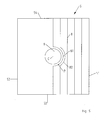
Fig. 2 ist ein weiteres Ausführungsbeispiel desVerfahrens 100 bei der Bearbeitung eines trapezförmigen Feldes 3 in einer Draufsicht dargestellt. Zu sehen ist, dass derPflug 1von dem Traktor 2 entlang der Richtung R aufdem Feld 3 gezogen wird, das lediglich einen einzigen Abschnitt 4 umfasst. Dabei verläuft die Richtung R bzw. dieFurchen 8 in ihrer Verlängerung durch den Zentralpunkt Z. Während des Pflügens wird nun laufend die Distanz D entlang des Kreisbogens B um den Zentralpunkt Z zu der Abschnittsgrenze 41 berechnet und dadurch die Arbeitsbreite A fortlaufend bestimmt. Dadurch ist es nicht notwendig, eine aufwändige Routenplanung durchzuführen, da die Berechnung wenig rechenaufwändig ist und fortlaufend während der Bearbeitung des Feldes 3 erfolgen kann.
- In the
Fig. 2 is a further embodiment of themethod 100 in the processing of atrapezoidal field 3 shown in a plan view. It can be seen that theplow 1 is pulled by thetractor 2 along the direction R on thefield 3, which comprises only asingle section 4. In the course of plowing, the distance D along the circular arc B around the central point Z to thesection boundary 41 is continuously calculated, thereby determining the working width A continuously. As a result, it is not necessary to carry out a complicated route planning, since the calculation is less computationally intensive and can take place continuously during the processing offield 3.
Das Feld 3 ist hier trapezförmig mit den Ecken 45 - 48 ausgebildet. Dadurch ergeben sich zwei Abschnittsgrenzen 41 und 43, die in der Verlängerung durch den Zentralpunkt Z verlaufen und den Winkel β miteinander einschließen. Weiterhin ist zu sehen, dass das trapezförmige Feld 3 eine schmale Seite 42 und eine breite Seite 44 aufweist, die jeweils die korrespondierenden Endpunkte 45, 46 bzw. 47, 48 verbinden. Diese werden zur Berechnung der minimalen und maximalen Furchenzahl herangezogen.The
Weiterhin ist zu sehen, dass sich der Pflug 1 gerade an einer Position P befindet. Diese wurde mit einem satellitengestützten Ortungssystem (GPS-System) bestimmt. Gemäß den Schritten 106 - 109 des zuvor beschriebenen Verfahrens 100 wird die Distanz D entlang des Kreisbogens B um den Zentralpunkt Z berechnet und die Arbeitsbreite A mittels der noch zu pflügenden Furchenzahl (zur Abschnittsgrenze 41 hin) berechnet.Furthermore, it can be seen that the
Mit diesem besonders einfachen Verfahren ist es möglich, die Arbeitsbreite A und die Fahrtrichtung R durch den Zentralpunkt Z zu bestimmen und es ist möglich, das Feld 3 ohne großen Aufwand für eine Routenplanung besonders gleichmäßig zu bearbeiten.With this particularly simple method, it is possible to determine the working width A and the direction of travel R through the central point Z and it is possible to work the
In
Weiterhin ist zu sehen, dass der Abschnitt 4 als Randabschnitt ausgebildet ist und zwei zueinander unter einem Winkel verlaufende Randabschnittsgrenzen 41 und 43 aufweist. Hierbei fällt die Randabschnittsgrenze 41 mit der Hauptabschnittsgrenze 53 zusammen. Darüber hinaus ist zu sehen, dass der Randabschnitt 4 durch die Eckpunkte 45 - 48 als Viereck definiert ist. Die beiden geraden Abschnittsgrenzen 41 und 43 verlaufen in ihrer Verlängerung durch den ersten Zentralpunkt Z1. Weiterhin sind die schmalen Seiten 42 und die breite Seite 44 zu sehen, über die die insgesamt zu pflügende Furchenzahl in dem Abschnitt 4 berechnet wird. Die Arbeitsbreite und die Furchen im Randabschnitt 4 werden genauso bestimmt, wie zuvor in Bezug auf
Weiterhin sind die beiden Randabschnitte 6 und 7 zu sehen, wobei die zugehörigen Zentralpunkte Z2 und Z3 innerhalb des Feldes 3 liegen.Furthermore, the two
Der Zentralpunkt Z2 des Abschnitts 6 wird durch die Verlängerung der Abschnittsgrenzen 61 und 63 als Schnittpunkt bestimmt. Weiterhin wird der Zentralpunkt Z3 des Abschnitts 7 als Schnittpunkt der verlängerten Abschnittsgrenzen 71 und 73 bestimmt. Hierbei fallen die Abschnittsgrenzen 63 und 73 jeweils mit der Hauptabschnittsgrenze 51 zusammen.The central point Z 2 of the
Bei der Fahrt auf dem Feld 3 wird fortlaufend die Position P des Pflugs durch ein Satellitenortungssystem bestimmt. Die Priorisierung des Zentralpunkts Z1, Z2 oder Z3 erfolgt dabei wie nachfolgend in Bezug auf die
- Für jeden der
Abschnitte den naheliegenden Endpunkt 45 die zweite Distanz d2 zum Zentralpunkt Z1 berechnet. Weiterhin wird fürden entfernten Endpunkt 48 die dritte Distanz d3 zum Zentralpunkt Z1 berechnet.
- For each of the
sections obvious end point 45, the second distance d 2 to the central point Z 1 is calculated. Furthermore, for theremote end point 48, the third distance d 3 to the central point Z 1 is calculated.
Nach der Ermittlung der aktuellen Pflugposition P mit dem Ortungssystem wird die erste Distanz d1 der Pflugposition P zum Zentralpunkt Z1 berechnet. Anschließend wird die erste Distanz d1 mit der dritten Distanz d3 verglichen. Ist die erste Distanz d1 größer als die dritte Distanz d3 so wird ein anderer Zentralpunkt gewählt. Ebenfalls wird ein anderer Zentralpunkt gewählt, falls die erste Distanz d1 kleiner als die zweite Distanz d2 ist. Diese Berechnung erfolgt auch für die Abschnitte 6 und 7. Falls kein Zentralpunkt mit dieser Berechnung priorisiert werden kann, so befindet sich der Pflug entweder außerhalb des Feldes oder innerhalb des Hauptabschnitts 5 mit einer gleichmäßigen Arbeitsbreite.After determining the current plow position P with the locating system, the first distance d 1 of the plow position P to the central point Z 1 is calculated. Subsequently, the first distance d 1 is compared with the third distance d 3 . If the first distance d 1 is greater than the third distance d 3 , another central point is selected. Also, another central point is selected if the first distance d 1 is smaller than the second distance d 2 . This calculation also applies to
Für den priorisierten Zentralpunkt, beispielsweise für Z1 wird dann die Arbeitsbreitenberechnung entsprechend der Schritte 106 - 109 in
In
Bei der Umfahrung des Hindernisses 9 mit dem Durchmesser C werden die Furchen 81 und 82 um das Hindernis 9 herumgeführt, wobei die Arbeitsbreite des Pflugs an der Position P mit einer Korrekturrechnung angepasst wird.As the
Bei der Korrekturrechnung wird, wie nachfolgend genauer beschrieben, eine Ausgleichszahl berechnet, die die Anzahl der Furchen darstellt, welche nach der Hindernisumfahrung zum erneuten vollständigen Geradeziehen der Fahrspur benötigt werden. Weiterhin kann mit dieser Ausgleichszahl fortlaufend die Arbeitsbreite bei der Hindernisumfahrt korrigiert werden.In the correction calculation, as described in more detail below, a compensation number is calculated, which represents the number of furrows needed after the obstacle avoidance to completely retrace the lane completely. Furthermore, with this compensation number continuously the working width can be corrected in the obstacle drive.
Die Ausgleichszahl wird wie folgt berechnet: Zunächst wird ein minimaler Abstand dadurch berechnet, dass die Länge der schmalsten Seite 52 um den Hindernisdurchmesser C vermindert wird.The compensation number is calculated as follows: First, a minimum distance is calculated by reducing the length of the
Durch die Differenz der Länge der breiten Seite 54 und dem zuvor berechneten minimalen Abstand ergibt sich dann eine Abstandsdifferenz.The difference between the length of the
Anschließend wird mittels einer Division der Abstandsdifferenz durch den Verstellbereich der Arbeitsbreite des Pflugs die Ausgleichszahl berechnet, welche die Anzahl benötigter Furchen angibt welche bei einer Hindernisumfahrung zum Wiedererreichen einer geraden Furche notwendig ist.Subsequently, by means of a division of the distance difference by the adjustment range of the working width of the plow, the compensation number is calculated, which indicates the number of required furrows which is necessary in the event of an obstacle avoidance for the purpose of reestablishing a straight furrow.
Hierdurch ist es besonders einfach im Bereich des Hindernisses 9 die Arbeitsbreite des Pflugs an der Position P zu berechnen.This makes it particularly easy to calculate the working width of the plow at the position P in the area of the
Weiterhin umfasst der zuvor in Bezug auf die Ausführungsbeispiele der
Es versteht sich, dass in den zuvor beschriebenen Ausführungsbeispielen genannte Merkmale nicht auf diese speziellen Kombinationen beschränkt sind und auch in beliebigen anderen Kombinationen möglich sind.It is understood that in the embodiments described above mentioned features are not limited to these specific combinations and are also possible in any other combinations.
Claims (15)
dadurch gekennzeichnet, dass
das Feld (3) in wenigstens einen Abschnitt (4) mit zwei geraden Abschnittsgrenzen (41, 43) unterteilt wird,
dass ein Zentralpunkt (Z) als Schnittpunkt der Abschnittsgrenzen (41, 43) oder deren gedachten Verlängerungen ermittelt wird,
dass eine Distanz (D) zwischen der Pflugposition (P) und einer der Abschnittsgrenzen (41) entlang eines Kreisbogens (B) um den Zentralpunkt (Z) berechnet wird, und
mittels der Distanz (D) die Arbeitsbreite (A) des Pflugs (1) bestimmt und/oder eingestellt wird.Method (100) for setting a working width (A) of a plow (1), wherein the plow position (P) is detected on a field (3) with a locating system,
characterized in that
dividing the field (3) into at least one section (4) with two straight section boundaries (41, 43),
a central point (Z) is determined as the intersection of the section boundaries (41, 43) or their imaginary extensions,
that a distance (D) between the plow position (P) and one of the section boundaries (41) along a circular arc (B) about the central point (Z) is calculated, and
by means of the distance (D) the working width (A) of the plow (1) is determined and / or adjusted.
Applications Claiming Priority (1)
| Application Number | Priority Date | Filing Date | Title |
|---|---|---|---|
| DE102014102030.8A DE102014102030A1 (en) | 2014-02-18 | 2014-02-18 | Method and control unit for setting a working width of a plow |
Publications (3)
| Publication Number | Publication Date |
|---|---|
| EP2918155A2 true EP2918155A2 (en) | 2015-09-16 |
| EP2918155A3 EP2918155A3 (en) | 2015-11-18 |
| EP2918155B1 EP2918155B1 (en) | 2019-05-29 |
Family
ID=52633201
Family Applications (1)
| Application Number | Title | Priority Date | Filing Date |
|---|---|---|---|
| EP15401007.8A Active EP2918155B1 (en) | 2014-02-18 | 2015-02-17 | Method and control unit for adjusting the operating width of a plough |
Country Status (2)
| Country | Link |
|---|---|
| EP (1) | EP2918155B1 (en) |
| DE (1) | DE102014102030A1 (en) |
Cited By (2)
| Publication number | Priority date | Publication date | Assignee | Title |
|---|---|---|---|---|
| DE102017105773A1 (en) | 2017-03-17 | 2018-09-20 | Lemken Gmbh & Co. Kg | Method for planning the processing of an agricultural field |
| EP4118943A1 (en) * | 2021-07-15 | 2023-01-18 | CLAAS E-Systems GmbH | Method for planning a field processing route of an agricultural working machine |
Families Citing this family (2)
| Publication number | Priority date | Publication date | Assignee | Title |
|---|---|---|---|---|
| DE102021132869A1 (en) | 2021-12-14 | 2023-06-15 | Amazonen-Werke H. Dreyer SE & Co. KG | Method of determining correction settings for an agricultural plow |
| DE102022107924A1 (en) | 2022-04-04 | 2023-10-05 | Amazonen-Werke H. Dreyer SE & Co. KG | Method for operating an agricultural machine system and agricultural machine system for processing an agricultural area |
Citations (2)
| Publication number | Priority date | Publication date | Assignee | Title |
|---|---|---|---|---|
| DE102004027242A1 (en) | 2004-06-03 | 2005-12-22 | Claas Selbstfahrende Erntemaschinen Gmbh | Route planning system for agricultural machines |
| EP2446725B1 (en) | 2010-10-26 | 2013-07-31 | Deere & Company | Method and System for Determining a Planned Path of a Vehicle |
Family Cites Families (2)
| Publication number | Priority date | Publication date | Assignee | Title |
|---|---|---|---|---|
| US7689356B2 (en) * | 2006-10-27 | 2010-03-30 | Cnh America Llc | Method and apparatus for creating curved swath patterns for farm machinery |
| US7706948B2 (en) * | 2007-03-02 | 2010-04-27 | Cnh America Llc | Method for creating spiral swaths for irregular field boundaries |
-
2014
- 2014-02-18 DE DE102014102030.8A patent/DE102014102030A1/en not_active Withdrawn
-
2015
- 2015-02-17 EP EP15401007.8A patent/EP2918155B1/en active Active
Patent Citations (2)
| Publication number | Priority date | Publication date | Assignee | Title |
|---|---|---|---|---|
| DE102004027242A1 (en) | 2004-06-03 | 2005-12-22 | Claas Selbstfahrende Erntemaschinen Gmbh | Route planning system for agricultural machines |
| EP2446725B1 (en) | 2010-10-26 | 2013-07-31 | Deere & Company | Method and System for Determining a Planned Path of a Vehicle |
Cited By (3)
| Publication number | Priority date | Publication date | Assignee | Title |
|---|---|---|---|---|
| DE102017105773A1 (en) | 2017-03-17 | 2018-09-20 | Lemken Gmbh & Co. Kg | Method for planning the processing of an agricultural field |
| WO2018166561A1 (en) | 2017-03-17 | 2018-09-20 | Lemken Gmbh & Co Kg | Method for planning the working of an agricultural field |
| EP4118943A1 (en) * | 2021-07-15 | 2023-01-18 | CLAAS E-Systems GmbH | Method for planning a field processing route of an agricultural working machine |
Also Published As
| Publication number | Publication date |
|---|---|
| DE102014102030A1 (en) | 2015-08-20 |
| EP2918155A3 (en) | 2015-11-18 |
| EP2918155B1 (en) | 2019-05-29 |
Similar Documents
| Publication | Publication Date | Title |
|---|---|---|
| EP2918155B1 (en) | Method and control unit for adjusting the operating width of a plough | |
| EP2221702B1 (en) | Method for creating reference lanes for agricultural vehicles | |
| DE102017103141A1 (en) | Agricultural machine system and method for planning lanes for processing an agricultural area | |
| DE102016121523A1 (en) | Method for predicatively generating data for controlling a route and an operating sequence for agricultural vehicles and machines | |
| EP2267566A2 (en) | Method and system for route planning | |
| EP3595427B1 (en) | Method for planning the working of an agricultural field | |
| DE102004027242A1 (en) | Route planning system for agricultural machines | |
| DE102006015203A1 (en) | Method for controlling agricultural machine systems | |
| EP2918157B2 (en) | Agricultural machine with part width control | |
| EP3537863A1 (en) | Method for predictively generating data for controlling a travel path and an operating sequence for agricultural vehicles and machines | |
| DE102014108075A1 (en) | Method for subdividing an output field into subfields | |
| EP3732945B1 (en) | Technique for creating an off-road profile with an agricultural machine | |
| DE102017103139A1 (en) | Method for determining lanes on an agricultural area | |
| DE2947724C2 (en) | Plow for cultivating the earth | |
| DE544439C (en) | Device for connecting agricultural equipment or working machines to a tractor | |
| EP4052550A1 (en) | Gradient compensation device for viticulture | |
| EP3014969B1 (en) | Method for controlling an agricultural distribution machine on an agricultural area | |
| EP3403496B1 (en) | Method for the determination of the required application rate for agricultural material | |
| DE102016223189A1 (en) | Method for calculating characteristic geometry and / or manipulated variables of a three-point linkage | |
| EP1527670A2 (en) | Method for controlling a mowing device mounted on a vehicle | |
| EP4118943A1 (en) | Method for planning a field processing route of an agricultural working machine | |
| EP3311639A1 (en) | Method for calculating characteristic geometry and/or the actuating variables of a three point hydraulic lift | |
| DE102022107924A1 (en) | Method for operating an agricultural machine system and agricultural machine system for processing an agricultural area | |
| DE102017103144A1 (en) | Method and device for classifying boundary sections of an agricultural area | |
| DE102017103140A1 (en) | Method and device for defining a reference axis on an agricultural surface |
Legal Events
| Date | Code | Title | Description |
|---|---|---|---|
| PUAI | Public reference made under article 153(3) epc to a published international application that has entered the european phase |
Free format text: ORIGINAL CODE: 0009012 |
|
| AK | Designated contracting states |
Kind code of ref document: A2 Designated state(s): AL AT BE BG CH CY CZ DE DK EE ES FI FR GB GR HR HU IE IS IT LI LT LU LV MC MK MT NL NO PL PT RO RS SE SI SK SM TR |
|
| AX | Request for extension of the european patent |
Extension state: BA ME |
|
| PUAL | Search report despatched |
Free format text: ORIGINAL CODE: 0009013 |
|
| AK | Designated contracting states |
Kind code of ref document: A3 Designated state(s): AL AT BE BG CH CY CZ DE DK EE ES FI FR GB GR HR HU IE IS IT LI LT LU LV MC MK MT NL NO PL PT RO RS SE SI SK SM TR |
|
| AX | Request for extension of the european patent |
Extension state: BA ME |
|
| RIC1 | Information provided on ipc code assigned before grant |
Ipc: A01B 3/24 20060101AFI20151012BHEP Ipc: A01B 3/36 20060101ALI20151012BHEP Ipc: A01B 69/00 20060101ALI20151012BHEP |
|
| RIN1 | Information on inventor provided before grant (corrected) |
Inventor name: FROESCHLE, HEIKE |
|
| 17P | Request for examination filed |
Effective date: 20160517 |
|
| RBV | Designated contracting states (corrected) |
Designated state(s): AL AT BE BG CH CY CZ DE DK EE ES FI FR GB GR HR HU IE IS IT LI LT LU LV MC MK MT NL NO PL PT RO RS SE SI SK SM TR |
|
| GRAP | Despatch of communication of intention to grant a patent |
Free format text: ORIGINAL CODE: EPIDOSNIGR1 |
|
| STAA | Information on the status of an ep patent application or granted ep patent |
Free format text: STATUS: GRANT OF PATENT IS INTENDED |
|
| INTG | Intention to grant announced |
Effective date: 20190218 |
|
| GRAS | Grant fee paid |
Free format text: ORIGINAL CODE: EPIDOSNIGR3 |
|
| GRAA | (expected) grant |
Free format text: ORIGINAL CODE: 0009210 |
|
| STAA | Information on the status of an ep patent application or granted ep patent |
Free format text: STATUS: THE PATENT HAS BEEN GRANTED |
|
| AK | Designated contracting states |
Kind code of ref document: B1 Designated state(s): AL AT BE BG CH CY CZ DE DK EE ES FI FR GB GR HR HU IE IS IT LI LT LU LV MC MK MT NL NO PL PT RO RS SE SI SK SM TR |
|
| REG | Reference to a national code |
Ref country code: GB Ref legal event code: FG4D Free format text: NOT ENGLISH |
|
| REG | Reference to a national code |
Ref country code: CH Ref legal event code: EP |
|
| REG | Reference to a national code |
Ref country code: AT Ref legal event code: REF Ref document number: 1137688 Country of ref document: AT Kind code of ref document: T Effective date: 20190615 |
|
| REG | Reference to a national code |
Ref country code: DE Ref legal event code: R096 Ref document number: 502015009181 Country of ref document: DE |
|
| REG | Reference to a national code |
Ref country code: IE Ref legal event code: FG4D Free format text: LANGUAGE OF EP DOCUMENT: GERMAN |
|
| REG | Reference to a national code |
Ref country code: NO Ref legal event code: T2 Effective date: 20190529 |
|
| REG | Reference to a national code |
Ref country code: NL Ref legal event code: MP Effective date: 20190529 |
|
| REG | Reference to a national code |
Ref country code: LT Ref legal event code: MG4D |
|
| PG25 | Lapsed in a contracting state [announced via postgrant information from national office to epo] |
Ref country code: SE Free format text: LAPSE BECAUSE OF FAILURE TO SUBMIT A TRANSLATION OF THE DESCRIPTION OR TO PAY THE FEE WITHIN THE PRESCRIBED TIME-LIMIT Effective date: 20190529 Ref country code: ES Free format text: LAPSE BECAUSE OF FAILURE TO SUBMIT A TRANSLATION OF THE DESCRIPTION OR TO PAY THE FEE WITHIN THE PRESCRIBED TIME-LIMIT Effective date: 20190529 Ref country code: PT Free format text: LAPSE BECAUSE OF FAILURE TO SUBMIT A TRANSLATION OF THE DESCRIPTION OR TO PAY THE FEE WITHIN THE PRESCRIBED TIME-LIMIT Effective date: 20190930 Ref country code: LT Free format text: LAPSE BECAUSE OF FAILURE TO SUBMIT A TRANSLATION OF THE DESCRIPTION OR TO PAY THE FEE WITHIN THE PRESCRIBED TIME-LIMIT Effective date: 20190529 Ref country code: FI Free format text: LAPSE BECAUSE OF FAILURE TO SUBMIT A TRANSLATION OF THE DESCRIPTION OR TO PAY THE FEE WITHIN THE PRESCRIBED TIME-LIMIT Effective date: 20190529 Ref country code: AL Free format text: LAPSE BECAUSE OF FAILURE TO SUBMIT A TRANSLATION OF THE DESCRIPTION OR TO PAY THE FEE WITHIN THE PRESCRIBED TIME-LIMIT Effective date: 20190529 Ref country code: HR Free format text: LAPSE BECAUSE OF FAILURE TO SUBMIT A TRANSLATION OF THE DESCRIPTION OR TO PAY THE FEE WITHIN THE PRESCRIBED TIME-LIMIT Effective date: 20190529 |
|
| PG25 | Lapsed in a contracting state [announced via postgrant information from national office to epo] |
Ref country code: GR Free format text: LAPSE BECAUSE OF FAILURE TO SUBMIT A TRANSLATION OF THE DESCRIPTION OR TO PAY THE FEE WITHIN THE PRESCRIBED TIME-LIMIT Effective date: 20190830 Ref country code: LV Free format text: LAPSE BECAUSE OF FAILURE TO SUBMIT A TRANSLATION OF THE DESCRIPTION OR TO PAY THE FEE WITHIN THE PRESCRIBED TIME-LIMIT Effective date: 20190529 Ref country code: BG Free format text: LAPSE BECAUSE OF FAILURE TO SUBMIT A TRANSLATION OF THE DESCRIPTION OR TO PAY THE FEE WITHIN THE PRESCRIBED TIME-LIMIT Effective date: 20190829 Ref country code: RS Free format text: LAPSE BECAUSE OF FAILURE TO SUBMIT A TRANSLATION OF THE DESCRIPTION OR TO PAY THE FEE WITHIN THE PRESCRIBED TIME-LIMIT Effective date: 20190529 |
|
| PG25 | Lapsed in a contracting state [announced via postgrant information from national office to epo] |
Ref country code: DK Free format text: LAPSE BECAUSE OF FAILURE TO SUBMIT A TRANSLATION OF THE DESCRIPTION OR TO PAY THE FEE WITHIN THE PRESCRIBED TIME-LIMIT Effective date: 20190529 Ref country code: NL Free format text: LAPSE BECAUSE OF FAILURE TO SUBMIT A TRANSLATION OF THE DESCRIPTION OR TO PAY THE FEE WITHIN THE PRESCRIBED TIME-LIMIT Effective date: 20190529 Ref country code: EE Free format text: LAPSE BECAUSE OF FAILURE TO SUBMIT A TRANSLATION OF THE DESCRIPTION OR TO PAY THE FEE WITHIN THE PRESCRIBED TIME-LIMIT Effective date: 20190529 Ref country code: CZ Free format text: LAPSE BECAUSE OF FAILURE TO SUBMIT A TRANSLATION OF THE DESCRIPTION OR TO PAY THE FEE WITHIN THE PRESCRIBED TIME-LIMIT Effective date: 20190529 Ref country code: RO Free format text: LAPSE BECAUSE OF FAILURE TO SUBMIT A TRANSLATION OF THE DESCRIPTION OR TO PAY THE FEE WITHIN THE PRESCRIBED TIME-LIMIT Effective date: 20190529 Ref country code: SK Free format text: LAPSE BECAUSE OF FAILURE TO SUBMIT A TRANSLATION OF THE DESCRIPTION OR TO PAY THE FEE WITHIN THE PRESCRIBED TIME-LIMIT Effective date: 20190529 |
|
| PG25 | Lapsed in a contracting state [announced via postgrant information from national office to epo] |
Ref country code: SM Free format text: LAPSE BECAUSE OF FAILURE TO SUBMIT A TRANSLATION OF THE DESCRIPTION OR TO PAY THE FEE WITHIN THE PRESCRIBED TIME-LIMIT Effective date: 20190529 Ref country code: IT Free format text: LAPSE BECAUSE OF FAILURE TO SUBMIT A TRANSLATION OF THE DESCRIPTION OR TO PAY THE FEE WITHIN THE PRESCRIBED TIME-LIMIT Effective date: 20190529 |
|
| REG | Reference to a national code |
Ref country code: DE Ref legal event code: R097 Ref document number: 502015009181 Country of ref document: DE |
|
| PG25 | Lapsed in a contracting state [announced via postgrant information from national office to epo] |
Ref country code: TR Free format text: LAPSE BECAUSE OF FAILURE TO SUBMIT A TRANSLATION OF THE DESCRIPTION OR TO PAY THE FEE WITHIN THE PRESCRIBED TIME-LIMIT Effective date: 20190529 |
|
| PLBE | No opposition filed within time limit |
Free format text: ORIGINAL CODE: 0009261 |
|
| STAA | Information on the status of an ep patent application or granted ep patent |
Free format text: STATUS: NO OPPOSITION FILED WITHIN TIME LIMIT |
|
| PG25 | Lapsed in a contracting state [announced via postgrant information from national office to epo] |
Ref country code: PL Free format text: LAPSE BECAUSE OF FAILURE TO SUBMIT A TRANSLATION OF THE DESCRIPTION OR TO PAY THE FEE WITHIN THE PRESCRIBED TIME-LIMIT Effective date: 20190529 |
|
| 26N | No opposition filed |
Effective date: 20200303 |
|
| PG25 | Lapsed in a contracting state [announced via postgrant information from national office to epo] |
Ref country code: SI Free format text: LAPSE BECAUSE OF FAILURE TO SUBMIT A TRANSLATION OF THE DESCRIPTION OR TO PAY THE FEE WITHIN THE PRESCRIBED TIME-LIMIT Effective date: 20190529 |
|
| REG | Reference to a national code |
Ref country code: CH Ref legal event code: PL |
|
| GBPC | Gb: european patent ceased through non-payment of renewal fee |
Effective date: 20200217 |
|
| REG | Reference to a national code |
Ref country code: BE Ref legal event code: MM Effective date: 20200229 |
|
| PG25 | Lapsed in a contracting state [announced via postgrant information from national office to epo] |
Ref country code: MC Free format text: LAPSE BECAUSE OF FAILURE TO SUBMIT A TRANSLATION OF THE DESCRIPTION OR TO PAY THE FEE WITHIN THE PRESCRIBED TIME-LIMIT Effective date: 20190529 Ref country code: LU Free format text: LAPSE BECAUSE OF NON-PAYMENT OF DUE FEES Effective date: 20200217 |
|
| PG25 | Lapsed in a contracting state [announced via postgrant information from national office to epo] |
Ref country code: CH Free format text: LAPSE BECAUSE OF NON-PAYMENT OF DUE FEES Effective date: 20200229 Ref country code: LI Free format text: LAPSE BECAUSE OF NON-PAYMENT OF DUE FEES Effective date: 20200229 |
|
| PG25 | Lapsed in a contracting state [announced via postgrant information from national office to epo] |
Ref country code: IE Free format text: LAPSE BECAUSE OF NON-PAYMENT OF DUE FEES Effective date: 20200217 Ref country code: GB Free format text: LAPSE BECAUSE OF NON-PAYMENT OF DUE FEES Effective date: 20200217 |
|
| PG25 | Lapsed in a contracting state [announced via postgrant information from national office to epo] |
Ref country code: BE Free format text: LAPSE BECAUSE OF NON-PAYMENT OF DUE FEES Effective date: 20200229 |
|
| REG | Reference to a national code |
Ref country code: DE Ref legal event code: R081 Ref document number: 502015009181 Country of ref document: DE Owner name: AMAZONEN-WERKE H. DREYER SE & CO. KG, DE Free format text: FORMER OWNER: AMAZONEN-WERKE H. DREYER GMBH & CO. KG, 49205 HASBERGEN, DE |
|
| PG25 | Lapsed in a contracting state [announced via postgrant information from national office to epo] |
Ref country code: MT Free format text: LAPSE BECAUSE OF FAILURE TO SUBMIT A TRANSLATION OF THE DESCRIPTION OR TO PAY THE FEE WITHIN THE PRESCRIBED TIME-LIMIT Effective date: 20190529 Ref country code: CY Free format text: LAPSE BECAUSE OF FAILURE TO SUBMIT A TRANSLATION OF THE DESCRIPTION OR TO PAY THE FEE WITHIN THE PRESCRIBED TIME-LIMIT Effective date: 20190529 |
|
| PG25 | Lapsed in a contracting state [announced via postgrant information from national office to epo] |
Ref country code: MK Free format text: LAPSE BECAUSE OF FAILURE TO SUBMIT A TRANSLATION OF THE DESCRIPTION OR TO PAY THE FEE WITHIN THE PRESCRIBED TIME-LIMIT Effective date: 20190529 Ref country code: IS Free format text: LAPSE BECAUSE OF FAILURE TO SUBMIT A TRANSLATION OF THE DESCRIPTION OR TO PAY THE FEE WITHIN THE PRESCRIBED TIME-LIMIT Effective date: 20190929 |
|
| PGFP | Annual fee paid to national office [announced via postgrant information from national office to epo] |
Ref country code: NO Payment date: 20230208 Year of fee payment: 9 Ref country code: AT Payment date: 20230125 Year of fee payment: 9 |
|
| PGFP | Annual fee paid to national office [announced via postgrant information from national office to epo] |
Ref country code: DE Payment date: 20221220 Year of fee payment: 9 |
|
| P01 | Opt-out of the competence of the unified patent court (upc) registered |
Effective date: 20230523 |
|
| PGFP | Annual fee paid to national office [announced via postgrant information from national office to epo] |
Ref country code: FR Payment date: 20231212 Year of fee payment: 10 |