EP2917741B1 - Analysis device for in vitro diagnostics - Google Patents
Analysis device for in vitro diagnostics Download PDFInfo
- Publication number
- EP2917741B1 EP2917741B1 EP13801630.8A EP13801630A EP2917741B1 EP 2917741 B1 EP2917741 B1 EP 2917741B1 EP 13801630 A EP13801630 A EP 13801630A EP 2917741 B1 EP2917741 B1 EP 2917741B1
- Authority
- EP
- European Patent Office
- Prior art keywords
- rack
- preparation
- rotor
- loading
- module
- Prior art date
- Legal status (The legal status is an assumption and is not a legal conclusion. Google has not performed a legal analysis and makes no representation as to the accuracy of the status listed.)
- Active
Links
- 238000004458 analytical method Methods 0.000 title claims description 83
- 238000000338 in vitro Methods 0.000 title claims description 7
- 238000002360 preparation method Methods 0.000 claims description 100
- 238000011068 loading method Methods 0.000 claims description 79
- 238000005070 sampling Methods 0.000 claims description 74
- 239000007788 liquid Substances 0.000 claims description 30
- 238000013519 translation Methods 0.000 claims description 15
- 239000003153 chemical reaction reagent Substances 0.000 claims description 5
- 238000007789 sealing Methods 0.000 claims description 5
- 238000003745 diagnosis Methods 0.000 claims description 2
- 238000003756 stirring Methods 0.000 description 22
- 238000005259 measurement Methods 0.000 description 18
- 238000013019 agitation Methods 0.000 description 13
- 238000001514 detection method Methods 0.000 description 9
- 238000006073 displacement reaction Methods 0.000 description 7
- 230000010355 oscillation Effects 0.000 description 7
- 239000013060 biological fluid Substances 0.000 description 6
- 238000012550 audit Methods 0.000 description 5
- 238000003780 insertion Methods 0.000 description 5
- 230000037431 insertion Effects 0.000 description 5
- 230000015271 coagulation Effects 0.000 description 4
- 238000005345 coagulation Methods 0.000 description 4
- 238000010790 dilution Methods 0.000 description 4
- 239000012895 dilution Substances 0.000 description 4
- 229920003229 poly(methyl methacrylate) Polymers 0.000 description 4
- 239000004926 polymethyl methacrylate Substances 0.000 description 4
- 238000003860 storage Methods 0.000 description 4
- 210000004369 blood Anatomy 0.000 description 3
- 239000008280 blood Substances 0.000 description 3
- 230000000295 complement effect Effects 0.000 description 3
- 238000002156 mixing Methods 0.000 description 3
- 239000000203 mixture Substances 0.000 description 3
- 230000003287 optical effect Effects 0.000 description 3
- 238000012360 testing method Methods 0.000 description 3
- 238000009534 blood test Methods 0.000 description 2
- 238000004891 communication Methods 0.000 description 2
- 238000000605 extraction Methods 0.000 description 2
- 238000004020 luminiscence type Methods 0.000 description 2
- 238000004519 manufacturing process Methods 0.000 description 2
- 229920003023 plastic Polymers 0.000 description 2
- 230000001105 regulatory effect Effects 0.000 description 2
- 239000003154 D dimer Substances 0.000 description 1
- 102000001554 Hemoglobins Human genes 0.000 description 1
- 108010054147 Hemoglobins Proteins 0.000 description 1
- 230000033228 biological regulation Effects 0.000 description 1
- 230000015572 biosynthetic process Effects 0.000 description 1
- 238000004159 blood analysis Methods 0.000 description 1
- 238000004820 blood count Methods 0.000 description 1
- 210000001772 blood platelet Anatomy 0.000 description 1
- 210000004027 cell Anatomy 0.000 description 1
- 238000009826 distribution Methods 0.000 description 1
- 210000003743 erythrocyte Anatomy 0.000 description 1
- 108010052295 fibrin fragment D Proteins 0.000 description 1
- 238000000684 flow cytometry Methods 0.000 description 1
- 238000010438 heat treatment Methods 0.000 description 1
- 230000002489 hematologic effect Effects 0.000 description 1
- 230000023597 hemostasis Effects 0.000 description 1
- 239000008240 homogeneous mixture Substances 0.000 description 1
- 210000000265 leukocyte Anatomy 0.000 description 1
- 239000000463 material Substances 0.000 description 1
- 238000000034 method Methods 0.000 description 1
- 238000005375 photometry Methods 0.000 description 1
- 238000004062 sedimentation Methods 0.000 description 1
- 239000000243 solution Substances 0.000 description 1
- 238000012546 transfer Methods 0.000 description 1
- 238000012800 visualization Methods 0.000 description 1
Images


Classifications
-
- G—PHYSICS
- G01—MEASURING; TESTING
- G01N—INVESTIGATING OR ANALYSING MATERIALS BY DETERMINING THEIR CHEMICAL OR PHYSICAL PROPERTIES
- G01N35/00—Automatic analysis not limited to methods or materials provided for in any single one of groups G01N1/00 - G01N33/00; Handling materials therefor
- G01N35/02—Automatic analysis not limited to methods or materials provided for in any single one of groups G01N1/00 - G01N33/00; Handling materials therefor using a plurality of sample containers moved by a conveyor system past one or more treatment or analysis stations
- G01N35/04—Details of the conveyor system
-
- G—PHYSICS
- G01—MEASURING; TESTING
- G01N—INVESTIGATING OR ANALYSING MATERIALS BY DETERMINING THEIR CHEMICAL OR PHYSICAL PROPERTIES
- G01N35/00—Automatic analysis not limited to methods or materials provided for in any single one of groups G01N1/00 - G01N33/00; Handling materials therefor
- G01N35/02—Automatic analysis not limited to methods or materials provided for in any single one of groups G01N1/00 - G01N33/00; Handling materials therefor using a plurality of sample containers moved by a conveyor system past one or more treatment or analysis stations
- G01N35/026—Automatic analysis not limited to methods or materials provided for in any single one of groups G01N1/00 - G01N33/00; Handling materials therefor using a plurality of sample containers moved by a conveyor system past one or more treatment or analysis stations having blocks or racks of reaction cells or cuvettes
-
- G—PHYSICS
- G01—MEASURING; TESTING
- G01N—INVESTIGATING OR ANALYSING MATERIALS BY DETERMINING THEIR CHEMICAL OR PHYSICAL PROPERTIES
- G01N35/00—Automatic analysis not limited to methods or materials provided for in any single one of groups G01N1/00 - G01N33/00; Handling materials therefor
- G01N2035/00465—Separating and mixing arrangements
- G01N2035/00524—Mixing by agitating sample carrier
-
- G—PHYSICS
- G01—MEASURING; TESTING
- G01N—INVESTIGATING OR ANALYSING MATERIALS BY DETERMINING THEIR CHEMICAL OR PHYSICAL PROPERTIES
- G01N35/00—Automatic analysis not limited to methods or materials provided for in any single one of groups G01N1/00 - G01N33/00; Handling materials therefor
- G01N35/02—Automatic analysis not limited to methods or materials provided for in any single one of groups G01N1/00 - G01N33/00; Handling materials therefor using a plurality of sample containers moved by a conveyor system past one or more treatment or analysis stations
- G01N35/04—Details of the conveyor system
- G01N2035/0401—Sample carriers, cuvettes or reaction vessels
- G01N2035/0403—Sample carriers with closing or sealing means
-
- G—PHYSICS
- G01—MEASURING; TESTING
- G01N—INVESTIGATING OR ANALYSING MATERIALS BY DETERMINING THEIR CHEMICAL OR PHYSICAL PROPERTIES
- G01N35/00—Automatic analysis not limited to methods or materials provided for in any single one of groups G01N1/00 - G01N33/00; Handling materials therefor
- G01N35/02—Automatic analysis not limited to methods or materials provided for in any single one of groups G01N1/00 - G01N33/00; Handling materials therefor using a plurality of sample containers moved by a conveyor system past one or more treatment or analysis stations
- G01N35/04—Details of the conveyor system
- G01N2035/0401—Sample carriers, cuvettes or reaction vessels
- G01N2035/0412—Block or rack elements with a single row of samples
- G01N2035/0415—Block or rack elements with a single row of samples moving in two dimensions in a horizontal plane
-
- G—PHYSICS
- G01—MEASURING; TESTING
- G01N—INVESTIGATING OR ANALYSING MATERIALS BY DETERMINING THEIR CHEMICAL OR PHYSICAL PROPERTIES
- G01N35/00—Automatic analysis not limited to methods or materials provided for in any single one of groups G01N1/00 - G01N33/00; Handling materials therefor
- G01N35/02—Automatic analysis not limited to methods or materials provided for in any single one of groups G01N1/00 - G01N33/00; Handling materials therefor using a plurality of sample containers moved by a conveyor system past one or more treatment or analysis stations
- G01N35/04—Details of the conveyor system
- G01N2035/0439—Rotary sample carriers, i.e. carousels
- G01N2035/0444—Rotary sample carriers, i.e. carousels for cuvettes or reaction vessels
-
- G—PHYSICS
- G01—MEASURING; TESTING
- G01N—INVESTIGATING OR ANALYSING MATERIALS BY DETERMINING THEIR CHEMICAL OR PHYSICAL PROPERTIES
- G01N35/00—Automatic analysis not limited to methods or materials provided for in any single one of groups G01N1/00 - G01N33/00; Handling materials therefor
- G01N35/02—Automatic analysis not limited to methods or materials provided for in any single one of groups G01N1/00 - G01N33/00; Handling materials therefor using a plurality of sample containers moved by a conveyor system past one or more treatment or analysis stations
- G01N35/04—Details of the conveyor system
- G01N2035/046—General conveyor features
- G01N2035/0465—Loading or unloading the conveyor
Definitions
- the present invention relates to an analysis device for in vitro diagnostics, and more particularly to a whole blood analysis device.
- the loading module comprises a storage element provided to allow a stack of racks oriented substantially horizontally, and extraction means arranged to extract the racks out of the storage element in the direction of the stirring module.
- the extraction means are more particularly arranged to move each rack in translation in a horizontal direction and parallel to the plane of said rack.
- the stirring module comprises displacement and tilting means arranged so as to move a rack from a position of introduction into the stirring module in which said rack extends substantially horizontally to a position of withdrawal of said module agitation wherein said rack extends substantially vertically.
- the analysis device described in the document FR 2 907 905 has a complex structure and high manufacturing costs.
- the present invention aims to remedy these drawbacks.
- the technical problem underlying the invention therefore consists in providing an analysis device for in vitro diagnostics which is of simple and economical structure, while ensuring a high analysis rate.
- the present invention relates to an analysis device for in vitro diagnostics, according to claim 1.
- Such a configuration of the stirring module and of the loading and unloading modules makes it possible to ensure a movement of the racks between the loading and unloading positions using simple movement means, which improves reliability and reduces costs. manufacturing costs of the analysis device according to the invention.
- such a configuration of the loading and unloading modules makes it possible to ensure automatic loading and unloading of the racks in and out of the analysis device according to the invention, for example by arranging the loading and unloading conveyors in look at the loading and unloading modules respectively. These arrangements make it possible to ensure high analysis rates.
- the analysis device can be used to perform in particular hematology analyzes, Blood Formula Count (BFS) analyzes, cytology analyzes, flow cytometry analyzes, analyzes. hematology, coagulation haemostasis analyzes, or to prepare slides for automatic microscopic observation of cells and to determine the rate of sedimentation, etc.
- BFS Blood Formula Count
- the stirring module is arranged such that the at least one rack extends substantially in the same plane in the first and second intermediate positions.
- the stirring module is arranged such that the at least one rack extends substantially vertically in the first and second intermediate positions.
- the first and second intermediate positions correspond respectively to positions of insertion and withdrawal of a rack in and out of the stirring module.
- the first and second intermediate positions are respectively arranged at one of the ends of the loading and unloading modules.
- the loading and unloading modules are arranged such that the first and second directions of movement are substantially perpendicular to the plane of the at least one rack.
- the loading and unloading modules are arranged to hold the at least one substantially vertical rack, and more particularly the containers received in said rack, during its movements in the first and second directions of movement.
- the stirring module is arranged to maintain the at least one substantially vertical rack, and more particularly the receptacles received in said rack, during its movements between the first and second intermediate positions.
- the first and second directions of movement are substantially parallel.
- the loading and unloading modules comprise for example respectively a first and a second conveyor.
- the first and second conveyors are advantageously belt or belt conveyors.
- the guidance direction is substantially perpendicular to the first and second directions of movement.
- the guidance direction and the first and second directions of movement are substantially horizontal under conditions of use.
- the guide means are arranged at the ends of the loading and unloading modules.
- the guide means are arranged to guide laterally in translation the at least one rack between the first and second intermediate positions in the direction of guidance.
- the stirring module and the loading and unloading modules define a generally U-shaped rack transport path.
- the rack transport path is substantially horizontal under conditions of 'use.
- the pivot axis of the guide means is substantially parallel to the guide direction.
- the pivot axis of the guide means is substantially horizontal under conditions of use.
- the guide means comprise a rack support delimiting a housing in which the at least one rack is able to slide in the guiding direction, the support of rack being mounted to pivot about the pivot axis.
- the housing delimited by the rack support is designed to simultaneously accommodate a plurality of racks.
- the rack support comprises a rack introduction portion and a rack removal portion, the translational drive means being arranged to translate the at least one received rack. in the housing of the rack holder between the rack introduction portion and the rack removal portion.
- the rack support extends substantially perpendicularly to the loading and unloading modules.
- the rack support is mounted to pivot about the pivot axis between at least a first angular position in which a rack is adapted to be inserted into or withdrawn from the rack support and a second angular position angularly offset from the first angular position, the pivot axis of the rack support being disposed below the housing of the rack support when the rack support is in its first angular position.
- the rack support extends substantially vertically in its first angular position.
- the rack support comprises a guide surface arranged to cooperate with the base of a rack during the sliding of said rack in the housing of the rack support, the pivot axis of the support rack being disposed below the guide surface when the rack support is in its first angular position.
- the rack support comprises at least a first guide wall arranged to cooperate with a side wall of a rack during the sliding of said rack in the housing of the rack support, and a wall of retainer arranged to cooperate with closure elements of receptacles received in said rack so as to retain the receptacles in said rack during the pivoting of the rack support.
- the rack support further comprises a second guide wall arranged to cooperate with a lower surface of a rack during the sliding of said rack in the housing of the rack support.
- the retaining wall is also arranged to cooperate with the closure elements of the receptacles received in said rack during the sliding of said rack in the housing of the rack support.
- the retaining wall comprises a passage orifice intended for the passage of a sampling needle.
- the pivoting means are arranged to pivot the guide means around the pivot axis according to an angular displacement of between 0 and 160 °, and for example between 0 and approximately 120 °. °.
- the rack support is inclined at an angle of approximately 120 ° relative to the vertical when it is in its second angular position.
- the sampling module is placed near the agitation module.
- the translational drive means are arranged to immobilize the at least one rack in at least one sampling position arranged between the first and second intermediate positions, the sampling module being arranged to taking a sample of biological fluid in at least one container received in said rack when said rack is immobilized in the at least one sampling position.
- the translational drive means are arranged to immobilize the at least one rack in a plurality of sampling positions arranged between the first and second intermediate positions, each sampling position corresponding to a position of said rack in which the module sampling device is arranged to take a sample of biological fluid in one of the containers received in said rack.
- the translational drive means are arranged to immobilize said rack in N distinct sampling positions.
- the translational drive means comprise at least one fork intended to cooperate with a rack received in the housing of the rack support, a guide rail extending parallel to the guidance direction. and on which the fork is slidably mounted, an endless belt, such as a toothed endless belt, connected to the fork, and a drive motor arranged to drive the endless belt.
- the stirring module is arranged to immobilize the guide means in a transfer position in which the at least one rack is able to be guided in translation between the first and second intermediate positions.
- the pivoting means comprise a drive motor, such as a stepping motor, coupled, for example by means of an endless belt, such as a belt. endless notched, to a pulley integral in rotation with the rack support and axis coincident with the pivot axis of the rack support.
- a drive motor such as a stepping motor
- an endless belt such as a belt. endless notched
- the analysis device comprises detection means arranged to detect the insertion of a rack in the housing of the rack support, and control means connected to the detection means and arranged to initiate pivoting of the rack support when the detecting means has detected the insertion of a rack into the housing of the rack support.
- the pivoting means are arranged to pivotally drive the guide means according to a rocking movement about the pivot axis.
- the pivoting means are for example arranged to generate at least twelve rockings per minute of the guide means around the pivot axis, preferably with pauses between the rockings so that the air bubble present in each receptacle received in the rack can travel the entire height of the container, and thus cause optimal mixing of the sample.
- the pivoting means are arranged to allow tilting of the rack between a position in which the rack is oriented upward and a position in which the rack is oriented downward, and more particularly between a position in which the containers received in the rack are oriented towards the up and a position in which the containers received in the rack face down.
- the loading rotor is removable.
- each housing provided on the loading rotor opens into the upper face of the loading rotor.
- At least two housings provided on the loading rotor have different dimensions. These arrangements allow the mounting of containers of different dimensions on the loading rotor.
- Each preparation bowl may for example extend in a plane substantially perpendicular to a diameter of the preparation rotor.
- the medium of each preparation cuvette passes through a diameter of the preparation rotor.
- the preparation cuvettes are distributed over the periphery of the preparation rotor, and preferably regularly distributed over the periphery of the preparation rotor.
- At least one preparation bowl has a rounded bottom, the concavity of which faces upwards.
- the preparation rotor is transparent.
- the preparation rotor is made of transparent plastic, such as polymethyl methacrylate (PMMA).
- PMMA polymethyl methacrylate
- the rotary drive means associated with the preparation rotor are advantageously arranged to drive the preparation rotor in rotation in a first direction and in a second direction opposite to the first direction.
- the rotary drive means associated with the preparation rotor are for example arranged to drive the preparation rotor alternately in rotation in the first and second directions, for example at an oscillation frequency corresponding to the natural oscillation frequency of the liquid. contained in the preparation cuvette (s).
- the means for driving in rotation associated with the preparation rotor comprise a stepping motor.
- the preparation and measurement module comprises regulating means arranged to regulate the temperature of the preparation cuvettes to a determined level.
- the preparation and measurement module comprises at least one measurement and / or analysis station arranged around the preparation rotor.
- the at least one measurement and / or analysis station is, for example, a spectrophotometric reading module, a fluorescence reading module, a luminescence reading module, a coagulation measurement module.
- the preparation rotor comprises a rotating body on which the preparation cuvettes are removably mounted.
- the analysis device comprises a supply station arranged to supply the rotary body with preparation cuvettes.
- the preparation rotor comprises a rotating body on which the preparation cuvettes are formed.
- the at least one rack comprises windows allowing optical reading of identification codes carried by the receptacles received on said rack.
- the sampling module comprises a sampling head equipped with a sampling needle, first displacement means arranged to move the sampling head in translation in a direction which is substantially horizontal and perpendicular to the guiding direction, and second displacement means arranged to move the sampling head in a substantially vertical direction.
- the sampling needle has a tip capable of piercing the closure elements of the receptacles received in the at least one rack.
- the sampling module comprises at least one rinsing well capable of receiving and rinsing the sampling needle from the sampling head.
- the loading and unloading modules comprise first and second guide means arranged to cooperate with complementary guide means provided on the at least one rack.
- the first and second guide means comprise for example respectively a first and a second guide rails able to cooperate with the complementary guide means provided on the at least one rack, and more particularly on the base of said rack.
- the loading and unloading modules each have a storage capacity of at least fifteen racks.
- each rack comprises a plurality of housings substantially aligned in the plane of said rack and intended to receive one of the corresponding containers.
- each housing comprises an introduction opening opening out to the outside of the rack and shaped to allow the introduction of the corresponding container into said housing.
- Each container is preferably removably mounted in the corresponding rack.
- each housing has a substantially circular section.
- each container is mounted to rotate freely in the corresponding housing.
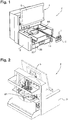
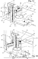
- the figure 1 represents an analysis device 2 for in vitro diagnosis, and more particularly for carrying out blood tests, such as whole blood tests.
- the analysis device 2 comprises a frame 3, a communication and display interface 4 mounted on the frame 3, and on-board electronics (not shown in the figures) housed in the frame 3.
- the communication and display interface 4 comprises for example a touch screen 5 connected to a PC type computer.
- the PC type computer is more particularly designed to record analysis requests loaded manually by an operator using a touch screen 5 or originating from a central unit of an analysis laboratory, to send requests for analysis. analysis with on-board electronics, to recover measured data, process them using specific algorithms, and make the results available to the operator.
- the analysis device 2 comprises a plurality of racks 6, also called racks or cassettes, each intended to receive a plurality of containers 7 equipped with sealing elements 8 and containing samples of biological liquid to be analyzed, such as blood samples.
- the containers 7 are sample tubes.
- Each rack 6 has a general parallelepipedal shape and comprises a plurality of housings 9, preferably cylindrical, aligned in the extension plane of said rack 6.
- the housings 9 are open upwards in order to allow easy introduction and removal of the containers. 7 in and out of the housings 9.
- each housing 9 is shaped so that the corresponding container 7 is mounted to rotate freely in said housing 9.
- Each rack 6 also comprises a first series of windows 11 allowing optical reading of identification codes carried by the receptacles 7, and a second series of windows 12 enabling visualization of the contents of said receptacles 7.
- each rack 6 further comprises a transverse notch 13, the function of which will be explained below.
- each rack 6 is designed to receive five containers 7. However, each rack 6 could be designed to receive less or more than five containers 7.
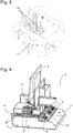
- the analysis device 2 further comprises a loading module 14 arranged to move each rack 6 loaded in the loading module 14 between a loading position P1 (see figure 5 ) and a first intermediate position P2 (see figure 10 ) in a first direction of movement D1 horizontal and perpendicular to the extension plane of said rack 6.
- the loading module 14 comprises a guide rail 15 extending parallel to the first direction of movement D1 and arranged to cooperate with the transverse notch 13 of each rack 6 loaded in the loading module 14 so as to guide said translation in translation. rack during its movements between the loading position P1 and the first intermediate position P2.
- the guide rail 15 has a dovetail section and the transverse notch 13 of each rack 6 has a complementary shape.
- the loading module 14 further comprises a conveyor 16 comprising two conveyor belts 17 each equipped with a plurality of drive fingers 18 (shown on the figure. figure 9 ) arranged to cooperate with the base of each rack 6 loaded in the loading module 14 so as to drive said rack in translation between the loading position P1 and the first intermediate position P2.
- the two conveyor belts 17 are driven by a motor 19 mounted on the frame 3 and more particularly shown in the figure. figure 11 .
- the analysis device 2 also comprises a stirring module 21 comprising a rack support 22 arranged to guide in translation at least one rack between the first intermediate position P2 and a second intermediate position P3 in a horizontal and perpendicular guiding direction D2. to the first direction of travel D1.
- the rack support 22 delimits a housing 23 into which is able to be inserted, preferably completely, at least one rack 6, and for example up to three racks 6 simultaneously.
- the rack support 22 comprises at least a first guide wall 24 arranged to cooperate with a side wall of a rack 6 introduced into the housing 23, a second guide wall 25 arranged to cooperate with the closure elements 8 of the containers. 7 received in the rack, and a third guide wall 26 arranged to cooperate with a lower surface of the rack 6.
- the second guide wall 25 is more particularly arranged to cooperate with the closure elements 8 of the receptacles 7 received in the rack 6 so as to retain the containers 7 in the rack 6 during the pivoting of the rack support 22, and thus also forms a retaining wall.
- the second guide wall 25 further comprises a passage orifice 25a intended for the passage of a sampling needle.
- the rack support 22 is mounted to pivot with respect to the frame 3 about a horizontal pivot axis A and parallel to the guiding direction D2.
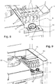
- the stirring module 21 also comprises pivoting means arranged to pivotally drive the rack support 22 about the pivot axis A between a first angular position in which the rack support 22 extends vertically (see figure 5 ) and a second angular position (see figure 6 ) wherein the rack support 22 is inclined relative to the vertical.
- the pivoting means are more particularly arranged to pivot the rack support 22 around the pivot axis A according to an angular displacement of between 0 and 160 °, and for example between 0 and approximately 120 °.
- the pivoting means are arranged to allow a tilting of a rack 6 loaded in the stirring module 21 between a position in which the containers 7 received in the rack 6 are oriented upward and a position in which the containers 7 received in the rack 6 are oriented downward.
- the pivoting means are arranged to pivot the rack support 22 according to a rocking movement around the pivot axis A.
- the pivot means are for example arranged to generate at least twelve rockings per minute of the rack support 22 around the pivot axis A, preferably with pauses between the swings so that the air bubble present in each container 7 received in a rack 6 loaded in the stirring module 21 can travel the entire height of the container 7, and thus cause optimal mixing of the sample contained in the container.
- the pivoting means comprise a stepping motor 27 (see figure 12 ) whose output shaft is coupled, for example by means of an endless belt 28, such as a toothed endless belt, to a pulley 29 integral in rotation with the carrier support 22 and of coincident axis with the pivot axis A.
- an endless belt 28 such as a toothed endless belt
- the stirring module 21 further comprises translational drive means arranged to drive in translation a rack 6 loaded in the stirring module 21 between the first and second intermediate positions P2, P3 in the guiding direction D2.
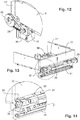
- the translational drive means comprise (see figures 13 and 14 ) in particular a guide rail 31 mounted on the frame 3 and extending parallel to the guide direction D2, and a fork 32 slidably mounted on the guide rail 31 and intended to cooperate with a rack 6 received in the housing 23 of the rack support 22.
- the fork 32 comprises in particular two parallel branches 33 spaced with respect to each other by a distance corresponding substantially to the length of a rack 6, and intended to extend through a lumen of passage 34 provided on the rack support 22.
- the translational drive means also comprise an endless belt 35, such as a toothed endless belt, connected to the fork 32, and a drive motor 36 (see figure 12 ) whose output shaft is provided with a pinion, preferably toothed, designed to drive the endless belt 35.
- an endless belt 35 such as a toothed endless belt
- a drive motor 36 see figure 12
- pinion preferably toothed
- the fork is provided with optical detection means arranged to detect the insertion of a rack 6 in the housing 23 of the rack support 22, and the analysis device 2 is provided with control means connected to the detection means and arranged to initiate the pivoting of the rack support 22 when the detection means have detected the insertion of a rack 6 in the housing 23.
- the rack support 22 and the translational drive means are preferably arranged to keep each rack 6 substantially vertical during its movements in the guiding direction D2.
- the analysis device 2 further comprises an unloading module 37 arranged to move a rack 6 between the second intermediate position P3 and an unloading position P4 in a second direction of movement D3 horizontal and perpendicular to the extension plane of said rack 6
- the second direction of movement D3 is advantageously parallel to the first direction of movement D1 and perpendicular to the guide direction D2.
- the unloading module 37 is substantially identical to the loading module 14.
- the unloading module 37 also comprises a guide rail 38 extending parallel to the second direction of movement D2 and arranged to cooperate with the transverse notch 13 of each rack 6 loaded in the unloading module 37 so as to guide said rack in translation during its movements between the second intermediate position P3 and the unloading position P4.
- the unloading module 37 further comprises a conveyor 39 comprising two conveyor belts 41 each equipped with a plurality of drive fingers.
- the two conveyor belts 41 are driven by a motor 42 mounted on the frame 3 and more particularly shown in the figure. figure 11 .
- the stirring 21, loading 14 and unloading 37 modules define a substantially horizontal carrier transport path in the general shape of a U.
- Such a configuration of the loading and unloading modules 14, 37 ensures loading and unloading. automatic unloading of the racks 6 in and out of the analysis device 2, for example by arranging loading conveyors and unloading respectively facing the loading and unloading modules 14, 37.
- the translational drive means are also arranged to vertically immobilize each rack received in the stirring module 21 in a plurality of sampling positions arranged between the first and second intermediate positions P2, P3, and more particularly in as many positions collection only receptacles 7 received in said rack 6.
- the analysis device 2 further comprises a sampling module 43 disposed near the agitation module 21 (see the figures 16 to 18 ).
- the sampling module 43 is arranged to take samples of biological fluid in the containers 7 received in each rack 6 loaded in the stirring module 21.
- the sampling module 43 is arranged to take a sample of biological fluid in one of the containers received in said rack 6.
- the sampling module 43 comprises in particular a sampling support 44, and a sampling head 45 mounted on the sampling support 44 and equipped with a sampling needle 46, the sampling needle 46 having a tip capable of piercing the elements. sealing 8 of the containers 7 received in each rack 6.
- the sampling module 43 further comprises first displacement means arranged to move the sampling head 44 in translation in a horizontal direction and perpendicular to the guiding direction D2, and second displacement means arranged to move the sampling head 44 in a vertical direction.
- the sampling module 43 further comprises a rinsing well 54 capable of receiving and rinsing the sampling needle 46 from the sampling head 45.
- the sampling module 43 could also include level detection means.
- level detection means make it possible, on the one hand, to avoid systematically plunging the sampling needle almost to the bottom of the receptacles, as do most hematology analyzers, which contaminates almost the entire length of the vessel. sampling needle, and on the other hand to be able to pipette reactive products into the vials with precision.
- the level detection means may for example comprise a capacitive detection system.
- the analysis device 2 comprises a loading rotor 55 arranged between the loading and unloading modules 14, 37 and having a substantially vertical axis of rotation.
- the loading rotor 55 comprises a plurality of housings 56 capable of receiving receptacles 57 containing samples of biological fluid to be analyzed or reactive products.
- Each housing 56 provided on the loading rotor 55 opens into the upper face of the loading rotor 55 in order to allow easy introduction and removal of the containers 57 in and out of the loading rotor 55.
- the loading rotor comprises housings 56 having different dimensions in order to allow the mounting of containers 57 of different dimensions on the loading rotor 55.
- the analysis device 2 also comprises means for driving in rotation associated with the loading rotor 55 and arranged to rotate the loading rotor 55 about its axis of rotation.
- the rotational drive means associated with the loading rotor 55 comprise for example a drive motor 58, such as a stepping motor, visible on the figure. figure 11 .
- the sampling module 43 is arranged to take, using the sampling head 45, samples or reactive products in the containers 57 received in the loading rotor 55.
- the loading rotor 55 makes it possible to load manually and at any time into the analysis device, receptacles 57 containing samples to be analyzed and which must be shaken manually beforehand, and / or bottles of reagent products.
- the analysis device 2 further comprises a preparation and measurement module 59 arranged inside the frame 3.
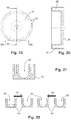
- the preparation and measurement module 59 comprises in particular a preparation rotor 61 with a substantially vertical axis of rotation. As shown more particularly on figures 19 to 22 , the preparation rotor 61 comprises a plurality of preparation bowls 62 regularly distributed over the periphery of the preparation rotor 61.
- the sampling module 43 is arranged to supply the preparation cuvettes 62 with biological liquid samples or with reactive products using the sampling head 45.
- the position of the sampling head 45 during feeding of the preparation cuvettes 62 is aligned with the positions of the sampling head 45 respectively when taking liquid from a container 57 received in the loading rotor 55, when taking samples from a container 7 received in a rack 6, and when rinsing the sampling needle 46.
- Each preparation bowl 62 advantageously extends in a plane perpendicular to a diameter of the preparation rotor 61 and the middle of each preparation bowl 62 passes through the corresponding diameter of the preparation rotor 61.
- the preparation rotor 61 comprises a rotating body on which the preparation cuvettes 62 are formed.
- the preparation rotor 61 could comprise a rotating body on which the preparation cuvettes are removably mounted.
- the analysis device 2 would include a supply station arranged to supply the rotary body with preparation cuvettes.
- each preparation bowl 62 has a rounded bottom whose concavity is turned upwards.
- the preparation and measurement module 59 further comprises rotational drive means associated with the preparation rotor 61. These rotational drive means are advantageously arranged to drive the preparation rotor 61 in rotation around its axis of rotation. alternately in a first direction and in a second direction opposite to the first direction, for example at an oscillation frequency corresponding to the natural oscillation frequency of the liquid contained in the preparation bowls 62.
- the means for driving in rotation associated with the preparation rotor 61 comprise a stepping motor 63 more particularly visible on the figure. figure 17 .
- the preparation and measurement module 59 may advantageously comprise regulation means arranged to regulate the temperature of the preparation cuvettes 62 to a determined level.
- the regulating means may comprise in particular a thermally conductive metallic plate 64 arranged under the preparation rotor 61 and heating means arranged to heat the thermally conductive metallic plate 64.
- the preparation rotor 61 is for example made of transparent plastic, such as polymethyl methacrylate (PMMA). These arrangements make it possible to perform various measurements through the material of the preparation rotor 61, such as photometric measurements.
- PMMA polymethyl methacrylate
- the analysis device advantageously comprises at least one measuring station arranged around the preparation rotor 61, such as a photometric measuring station suitable for measuring in particular the hemoglobin level in the sample to be analyzed, or the level of D-dimer or CRP in the sample to be analyzed.
- a photometric measuring station suitable for measuring in particular the hemoglobin level in the sample to be analyzed, or the level of D-dimer or CRP in the sample to be analyzed.
- the analysis device 2 could furthermore also comprise a spectrophotometric reading module, a fluorescence reading module, a luminescence reading module or even a coagulation measurement module arranged around the preparation rotor 61.
- the analysis device 2 may further include one or more cytometric measuring heads 65 which make it possible to perform all the hematology measurements relating to the blood count with precision.
- the analysis device 2 could for example comprise a first cytometric measuring head 65 for carrying out measurements of red blood cells or platelets, and a second cytometric measuring head 65 for carrying out measurements of white blood cells. These arrangements make it possible to carry out measurements in parallel, and therefore to increase the rate of analysis of the analysis device 2 according to the invention.
- the analysis device 2 also comprises a flat container 66 arranged under the loading and unloading modules 14, 37, and intended to contain isotonic dilution liquid acting as system liquid.
- the flat can 66 is advantageously provided with a rubber stopper pierced automatically at the end of the stroke by a suitable piercing member, which both makes the system liquid available to the analysis device 2, but also allows the open air.
- the system liquid will be heated by known devices.
- the container intended to receive used liquid is not shown in the figures.
- the operation of the analysis device 2 is as follows.
- Racks 6 provided with receptacles 7 containing samples of biological liquid to be analyzed are loaded manually or automatically into the loading module 14. These racks 6 are successively brought to the rack support 22 with a view to their agitation using the agitation module 21.
- each rack 6 is then moved to a first sampling position.
- the sampling head 45 of the sampling module 43 is then moved such that the sampling needle 46 passes through the passage opening 25a provided on the second guide wall 25 and takes a predetermined volume of biological fluid sample at analyze in a first container 7 received in the rack 6 immobilized in the first sampling position.
- the second guide wall 25 which cooperates with the closure element 8 of the first container 7, maintains the first container 7 in the housing 23 of the rack support 22.
- sampling head 45 of the sampling module 43 is then moved such that the sampling needle 46 introduces the predetermined volume of sample into a preparation cuvette 62 of the preparation rotor 61. Then, system liquid withdrawn from it. flat can 66 is introduced, using an appropriate feed station, into said preparation cuvette 62 in order to carry out a first dilution of the biological liquid to be analyzed.
- the preparation rotor is rotated around its axis of rotation alternately in a first direction S1 and in a second direction S2 opposite to the first direction S1, according to an oscillation frequency corresponding substantially to the natural oscillation frequency of the mixture contained in the preparation bowl 62.
- Such reciprocating rotational movements of the preparation rotor 61 generate movements of the liquids contained in the preparation bowl 62 as shown on the figure. figure 22 and ensure optimum mixing of these liquids, due to the arrangement of the preparation cuvettes 62 relative to the axis of rotation of the preparation rotor and the shape of the preparation cuvettes 62. It should be noted that the walls sides of the preparation basins are high enough to avoid liquid overflows during these oscillations.
- the mixture obtained is aspirated by the sampling needle 46 and dispensed into an empty preparation cuvette 62, for example to carry out a second dilution.
- the preparation rotor is driven in rotation in order to position the preparation cuvette 62 containing the mixture to be analyzed in front of a distribution station for the Lyse reagents to obtain the solutions ready for carrying out tests. haematological measurements.
- the various preparation cuvettes 62 are rinsed using an appropriate rinsing station if they are irremovable, or they are replaced by other preparation cuvettes if they are disposable, with a view to the analysis of another receptacle 7 received in the rack 6 in the sampling position.
- the translational drive means move the corresponding rack 6 into a second sampling position, so as to allow the taking of a sample in a second receptacle 7 housed in said rack 6 and perform, using the sampling module 43, and the analysis of this sample. These steps are repeated so as to allow the analysis of the samples contained in the various containers 7 received in the rack 6.
- the rack 6 When the samples contained in the various receptacles 7 housed in the disposed rack 6 have been analyzed, the rack 6 is moved to the second intermediate position P3 with a view to its unloading using the unloading module 37. However, if necessary, the rack 6 can be returned to a sampling position by reversing the direction of operation of the drive motors 36, 42 in order to carry out a new analysis of a sample contained in one of the containers housed in said rack 6.
- the analysis device 2 makes it possible to carry out specific or urgent analyzes using the loading rotor 55 by placing therein receptacles 57 containing samples of biological liquid to be analyzed or specific reactive products.
- the loading rotor 55 is rotated to dispose the desired container 57 in a predetermined position (see figure 16 ) allowing a sampling of the liquid contained in the latter using the sampling needle 46, this liquid then being introduced into a preparation bowl 62 of the preparation rotor 61.
Description
La présente invention concerne un dispositif d'analyse pour diagnostic in vitro, et plus particulièrement un dispositif d'analyse sur sang total.The present invention relates to an analysis device for in vitro diagnostics, and more particularly to a whole blood analysis device.
Le document
- une pluralité de portoirs destinés à recevoir des récipients équipés d'éléments d'obturation et contenants des échantillons de liquide biologique à analyser,
- un module de chargement agencé pour déplacer chaque portoir entre une position de chargement et une première position intermédiaire,
- un module d'agitation agencé pour déplacer chaque portoir entre la première position intermédiaire et une deuxième position intermédiaire et pour agiter ledit portoir,
- un module de déchargement agencé pour déplacer chaque portoir entre la deuxième position intermédiaire et une position de déchargement, et
- un module de prélèvement agencé pour prélever des échantillons de liquide biologique dans les récipients reçus dans l'au moins un portoir.
- a plurality of racks intended to receive receptacles equipped with sealing elements and containing samples of biological liquid to be analyzed,
- a loading module arranged to move each rack between a loading position and a first intermediate position,
- an agitation module arranged to move each rack between the first intermediate position and a second intermediate position and to agitate said rack,
- an unloading module arranged to move each rack between the second intermediate position and an unloading position, and
- a sampling module designed to take samples of biological liquid from the containers received in the at least one rack.
Selon le document
Un tel positionnement à plat des portoirs dans l'élément de stockage nécessite un chargement manuel des portoirs dans ce dernier, ce qui implique d'une part des manipulations fastidieuses pour un opérateur, et d'autre une faible cadence d'analyse.Such a flat positioning of the racks in the storage element requires manual loading of the racks into the latter, which involves, on the one hand, tedious operations for an operator, and on the other hand, a low analysis rate.
De plus, selon le document
De par cette configuration des modules de chargement, de déchargement et d'agitation, le dispositif d'analyse décrit dans le document
Un état de l'art pertinent se trouve également dans la divulgation du document
La présente invention vise à remédier à ces inconvénients.The present invention aims to remedy these drawbacks.
Le problème technique à la base de l'invention consiste donc à fournir un dispositif d'analyse pour diagnostic in vitro qui soit de structure simple et économique, tout en assurant une cadence d'analyse élevée.The technical problem underlying the invention therefore consists in providing an analysis device for in vitro diagnostics which is of simple and economical structure, while ensuring a high analysis rate.
A cet effet, la présente invention concerne un dispositif d'analyse pour diagnostic in vitro, selon la revendication 1.To this end, the present invention relates to an analysis device for in vitro diagnostics, according to
Une telle configuration du module d'agitation et des modules de chargement et de déchargement permet d'assurer un déplacement des portoirs entre les positions de chargement et de déchargement à l'aide de moyens de déplacement simples, ce qui améliore la fiabilité et diminue les coûts de fabrication du dispositif d'analyse selon l'invention.Such a configuration of the stirring module and of the loading and unloading modules makes it possible to ensure a movement of the racks between the loading and unloading positions using simple movement means, which improves reliability and reduces costs. manufacturing costs of the analysis device according to the invention.
En outre, une telle configuration des modules de chargement et de déchargement permet d'assurer un chargement et un déchargement automatiques des portoirs dans et hors du dispositif d'analyse selon l'invention, par exemple en disposant des convoyeurs de chargement et de déchargement en regard respectivement des modules de chargement et de déchargement. Ces dispositions permettent d'assurer des cadences d'analyse élevées.In addition, such a configuration of the loading and unloading modules makes it possible to ensure automatic loading and unloading of the racks in and out of the analysis device according to the invention, for example by arranging the loading and unloading conveyors in look at the loading and unloading modules respectively. These arrangements make it possible to ensure high analysis rates.
Il convient de noter que le dispositif d'analyse selon l'invention peut être utilisé pour effectuer notamment des analyses d'hématologie, des analyses de Numération Formule Sanguine (NFS), des analyses de cytologie, des analyses de cytométrie en flux, des analyses d'immuno-hématologie, des analyses de coagulation hémostase, ou encore pour préparer des lames pour observation automatique par microscope de cellules et pour déterminer la vitesse de sédimentation, etc.It should be noted that the analysis device according to the invention can be used to perform in particular hematology analyzes, Blood Formula Count (BFS) analyzes, cytology analyzes, flow cytometry analyzes, analyzes. hematology, coagulation haemostasis analyzes, or to prepare slides for automatic microscopic observation of cells and to determine the rate of sedimentation, etc.
Selon un mode de réalisation de l'invention, le module d'agitation est agencé de telle sorte que l'au moins un portoir s'étend sensiblement dans un même plan dans les première et deuxième positions intermédiaires.According to one embodiment of the invention, the stirring module is arranged such that the at least one rack extends substantially in the same plane in the first and second intermediate positions.
Selon un mode de réalisation de l'invention, le module d'agitation est agencé de telle sorte que l'au moins un portoir s'étend sensiblement verticalement dans les première et deuxième positions intermédiaires.According to one embodiment of the invention, the stirring module is arranged such that the at least one rack extends substantially vertically in the first and second intermediate positions.
De façon avantageuse, les première et deuxième positions intermédiaires correspondent respectivement à des positions d'insertion et de retrait d'un portoir dans et hors du module d'agitation.Advantageously, the first and second intermediate positions correspond respectively to positions of insertion and withdrawal of a rack in and out of the stirring module.
Avantageusement, les première et deuxième positions intermédiaires sont respectivement disposées à l'une des extrémités des modules de chargement et de déchargement.Advantageously, the first and second intermediate positions are respectively arranged at one of the ends of the loading and unloading modules.
Selon un mode de réalisation de l'invention, les modules de chargement et de déchargement sont agencés de telle sorte que les première et deuxième directions de déplacement sont sensiblement perpendiculaires au plan de l'au moins un portoir.According to one embodiment of the invention, the loading and unloading modules are arranged such that the first and second directions of movement are substantially perpendicular to the plane of the at least one rack.
Selon une caractéristique de l'invention, les modules de chargement et de déchargement sont agencés pour maintenir l'au moins un portoir sensiblement vertical, et plus particulièrement les récipients reçus dans ledit portoir, lors de ses déplacements selon les première et deuxième directions de déplacement.According to one characteristic of the invention, the loading and unloading modules are arranged to hold the at least one substantially vertical rack, and more particularly the containers received in said rack, during its movements in the first and second directions of movement.
Selon un mode de réalisation de l'invention, le module d'agitation est agencé pour maintenir l'au moins un portoir sensiblement vertical, et plus particulièrement les récipients reçus dans ledit portoir, lors de ses déplacements entre les première et deuxième positions intermédiaires.According to one embodiment of the invention, the stirring module is arranged to maintain the at least one substantially vertical rack, and more particularly the receptacles received in said rack, during its movements between the first and second intermediate positions.
Selon un mode de réalisation de l'invention, les première et deuxième directions de déplacement sont sensiblement parallèles.According to one embodiment of the invention, the first and second directions of movement are substantially parallel.
Les modules de chargement et de déchargement comportent par exemple respectivement un premier et un deuxième convoyeurs. Les premier et deuxième convoyeurs sont avantageusement des convoyeurs à courroie ou à bande.The loading and unloading modules comprise for example respectively a first and a second conveyor. The first and second conveyors are advantageously belt or belt conveyors.
Selon un mode de réalisation de l'invention, la direction de guidage est sensiblement perpendiculaire aux première et deuxième directions de déplacement.According to one embodiment of the invention, the guidance direction is substantially perpendicular to the first and second directions of movement.
Selon un mode de réalisation de l'invention, la direction de guidage et les première et deuxième directions de déplacement sont sensiblement horizontales en conditions d'utilisation.According to one embodiment of the invention, the guidance direction and the first and second directions of movement are substantially horizontal under conditions of use.
Selon un mode de réalisation de l'invention, les moyens de guidage sont disposés aux extrémités des modules de chargement et de déchargement.According to one embodiment of the invention, the guide means are arranged at the ends of the loading and unloading modules.
Selon un mode de réalisation de l'invention, les moyens de guidage sont agencés pour guider latéralement en translation l'au moins un portoir entre les première et deuxième positions intermédiaires selon la direction de guidageAccording to one embodiment of the invention, the guide means are arranged to guide laterally in translation the at least one rack between the first and second intermediate positions in the direction of guidance.
Selon un mode de réalisation de l'invention, le module d'agitation et les modules de chargement et de déchargement définissent un chemin de transport de portoir en forme générale de U. Avantageusement, le chemin de transport de portoir est sensiblement horizontal en conditions d'utilisation.According to one embodiment of the invention, the stirring module and the loading and unloading modules define a generally U-shaped rack transport path. Advantageously, the rack transport path is substantially horizontal under conditions of 'use.
Avantageusement, l'axe de pivotement des moyens de guidage est sensiblement parallèle à la direction de guidage. De façon avantageuse, l'axe de pivotement des moyens de guidage est sensiblement horizontal en conditions d'utilisation.Advantageously, the pivot axis of the guide means is substantially parallel to the guide direction. Advantageously, the pivot axis of the guide means is substantially horizontal under conditions of use.
Selon un mode de réalisation de l'invention, les moyens de guidage comportent un support de portoir délimitant un logement dans lequel est apte à coulisser l'au moins un portoir selon la direction de guidage, le support de portoir étant monté pivotant autour de l'axe de pivotement. De façon avantageuse, le logement délimité par le support de portoir est agencé pour loger simultanément une pluralité de portoirs.According to one embodiment of the invention, the guide means comprise a rack support delimiting a housing in which the at least one rack is able to slide in the guiding direction, the support of rack being mounted to pivot about the pivot axis. Advantageously, the housing delimited by the rack support is designed to simultaneously accommodate a plurality of racks.
Selon un mode de réalisation de l'invention, le support de portoir comporte une portion d'introduction de portoir et une portion de retrait de portoir, les moyens d'entraînement en translation étant agencés pour entraîner en translation l'au moins un portoir reçu dans le logement du support de portoir entre la portion d'introduction de portoir et la portion de retrait de portoir.According to one embodiment of the invention, the rack support comprises a rack introduction portion and a rack removal portion, the translational drive means being arranged to translate the at least one received rack. in the housing of the rack holder between the rack introduction portion and the rack removal portion.
Avantageusement, le support de portoir s'étend sensiblement perpendiculairement aux modules de chargement et de déchargement.Advantageously, the rack support extends substantially perpendicularly to the loading and unloading modules.
Selon un mode de réalisation de l'invention, le support de portoir est monté pivotant autour de l'axe de pivotement entre au moins une première position angulaire dans laquelle un portoir est apte à être insérer dans ou retirer hors du support de portoir et une deuxième position angulaire décalée angulairement de la première position angulaire, l'axe de pivotement du support de portoir étant disposé en dessous du logement du support de portoir lorsque le support de portoir est dans sa première position angulaire. Ces dispositions permettent d'assurer une agitation simple et efficace des récipients contenus dans un portoir disposé dans le module d'agitation.According to one embodiment of the invention, the rack support is mounted to pivot about the pivot axis between at least a first angular position in which a rack is adapted to be inserted into or withdrawn from the rack support and a second angular position angularly offset from the first angular position, the pivot axis of the rack support being disposed below the housing of the rack support when the rack support is in its first angular position. These arrangements make it possible to ensure simple and effective agitation of the containers contained in a rack placed in the agitation module.
Avantageusement, le support de portoir s'étend sensiblement verticalement dans sa première position angulaire.Advantageously, the rack support extends substantially vertically in its first angular position.
Selon un mode de réalisation de l'invention, le support de portoir comporte une surface de guidage agencée pour coopérer avec l'embase d'un portoir lors du coulissement dudit portoir dans le logement du support de portoir, l'axe de pivotement du support de portoir étant disposé en dessous de la surface de guidage lorsque le support de portoir est dans sa première position angulaire.According to one embodiment of the invention, the rack support comprises a guide surface arranged to cooperate with the base of a rack during the sliding of said rack in the housing of the rack support, the pivot axis of the support rack being disposed below the guide surface when the rack support is in its first angular position.
Selon un mode de réalisation de l'invention, le support de portoir comporte au moins une première paroi de guidage agencée pour coopérer avec une paroi latérale d'un portoir lors du coulissement dudit portoir dans le logement du support de portoir, et une paroi de retenue agencée pour coopérer avec des éléments d'obturation de récipients reçus dans ledit portoir de manière à retenir les récipients dans ledit portoir lors du pivotement du support de portoir. Une telle configuration du support de portoir assure un guidage optimal des portoirs entre les première et deuxième positions intermédiaires, tout en permettant l'utilisation de portoirs simples et peu onéreux.According to one embodiment of the invention, the rack support comprises at least a first guide wall arranged to cooperate with a side wall of a rack during the sliding of said rack in the housing of the rack support, and a wall of retainer arranged to cooperate with closure elements of receptacles received in said rack so as to retain the receptacles in said rack during the pivoting of the rack support. Such a configuration of the rack support ensures optimal guidance of the racks between the first and second intermediate positions, while allowing the use of simple and inexpensive racks.
Selon un mode de réalisation de l'invention, le support de portoir comporte en outre une deuxième paroi de guidage agencée pour coopérer avec une surface inférieure d'un portoir lors du coulissement dudit portoir dans le logement du support de portoir.According to one embodiment of the invention, the rack support further comprises a second guide wall arranged to cooperate with a lower surface of a rack during the sliding of said rack in the housing of the rack support.
Selon un mode de réalisation de l'invention, la paroi de retenue est également agencée pour coopérer avec les éléments d'obturation des récipients reçus dans ledit portoir lors du coulissement dudit portoir dans le logement du support de portoir.According to one embodiment of the invention, the retaining wall is also arranged to cooperate with the closure elements of the receptacles received in said rack during the sliding of said rack in the housing of the rack support.
Selon un mode de réalisation de l'invention, la paroi de retenue comporte un orifice de passage destiné au passage d'une aiguille de prélèvement.According to one embodiment of the invention, the retaining wall comprises a passage orifice intended for the passage of a sampling needle.
Selon un mode de réalisation de l'invention, les moyens de pivotement sont agencés pour entraîner en pivotement les moyens de guidage autour de l'axe de pivotement selon un débattement angulaire compris entre 0 et 160°, et par exemple entre 0 et environ 120°.According to one embodiment of the invention, the pivoting means are arranged to pivot the guide means around the pivot axis according to an angular displacement of between 0 and 160 °, and for example between 0 and approximately 120 °. °.
Avantageusement, le support de portoir est incliné d'un angle d'environ 120° par rapport à la verticale lorsqu'il est dans sa deuxième position angulaire.Advantageously, the rack support is inclined at an angle of approximately 120 ° relative to the vertical when it is in its second angular position.
Selon un mode de réalisation de l'invention, le module de prélèvement est disposé à proximité du module d'agitation.According to one embodiment of the invention, the sampling module is placed near the agitation module.
Selon un mode de réalisation de l'invention, les moyens d'entraînement en translation sont agencés pour immobiliser l'au moins un portoir dans au moins une position de prélèvement disposée entre les première et deuxième positions intermédiaires, le module de prélèvement étant agencé pour prélever un échantillon de liquide biologique dans au moins un récipient reçu dans ledit portoir lorsque ledit portoir est immobilisé dans l'au moins une position de prélèvement.According to one embodiment of the invention, the translational drive means are arranged to immobilize the at least one rack in at least one sampling position arranged between the first and second intermediate positions, the sampling module being arranged to taking a sample of biological fluid in at least one container received in said rack when said rack is immobilized in the at least one sampling position.
De préférence, les moyens d'entraînement en translation sont agencés pour immobiliser l'au moins un portoir dans une pluralité de positions de prélèvement disposées entre les première et deuxième positions intermédiaires, chaque position de prélèvement correspondant à une position dudit portoir dans laquelle le module de prélèvement est agencé pour prélever un échantillon de liquide biologique dans l'un des récipients reçus dans ledit portoir. Par exemple, lorsque N récipients sont reçus dans le portoir, les moyens d'entraînement en translation sont agencés pour immobiliser ledit portoir dans N positions de prélèvement distinctes.Preferably, the translational drive means are arranged to immobilize the at least one rack in a plurality of sampling positions arranged between the first and second intermediate positions, each sampling position corresponding to a position of said rack in which the module sampling device is arranged to take a sample of biological fluid in one of the containers received in said rack. For example, when N containers are received in the rack, the translational drive means are arranged to immobilize said rack in N distinct sampling positions.
Selon un mode de réalisation de l'invention, les moyens d'entraînement en translation comportent au moins une fourche destinée à coopérer avec un portoir reçu dans le logement du support de portoir, un rail de guidage s'étendant parallèlement à la direction de guidage et sur lequel est montée coulissante la fourche, une courroie sans fin, telle qu'une courroie sans fin crantée, reliée à la fourche, et un moteur d'entraînement agencé pour entraîner la courroie sans fin.According to one embodiment of the invention, the translational drive means comprise at least one fork intended to cooperate with a rack received in the housing of the rack support, a guide rail extending parallel to the guidance direction. and on which the fork is slidably mounted, an endless belt, such as a toothed endless belt, connected to the fork, and a drive motor arranged to drive the endless belt.
Selon un mode de réalisation de l'invention, le module d'agitation est agencé pour immobiliser les moyens de guidage dans une position de transfert dans laquelle l'au moins un portoir est apte à être guider en translation entre les première et deuxième positions intermédiaires.According to one embodiment of the invention, the stirring module is arranged to immobilize the guide means in a transfer position in which the at least one rack is able to be guided in translation between the first and second intermediate positions. .
Selon un mode de réalisation de l'invention, les moyens de pivotement comportent un moteur d'entraînement, tel qu'un moteur pas à pas, couplé, par exemple par l'intermédiaire d'une courroie sans fin, telle qu'une courroie sans fin crantée, à une poulie solidaire en rotation du support de portoir et d'axe confondu avec l'axe de pivotement du support de portoir.According to one embodiment of the invention, the pivoting means comprise a drive motor, such as a stepping motor, coupled, for example by means of an endless belt, such as a belt. endless notched, to a pulley integral in rotation with the rack support and axis coincident with the pivot axis of the rack support.
Selon un mode de réalisation de l'invention, le dispositif d'analyse comporte des moyens de détection agencés pour détecter l'insertion d'un portoir dans le logement du support de portoir, et des moyens de commande reliés aux moyens de détection et agencés pour initier le pivotement du support de portoir lorsque les moyens de détection ont détectés l'insertion d'un portoir dans le logement du support de portoir.According to one embodiment of the invention, the analysis device comprises detection means arranged to detect the insertion of a rack in the housing of the rack support, and control means connected to the detection means and arranged to initiate pivoting of the rack support when the detecting means has detected the insertion of a rack into the housing of the rack support.
Selon un mode de réalisation de l'invention, les moyens de pivotement sont agencés pour entraîner en pivotement les moyens de guidage selon un mouvement de balancement autour de l'axe de pivotement. Les moyens de pivotement sont par exemple agencés pour générer au moins douze balancements par minutes des moyens de guidage autour de l'axe de pivotement, avec de préférence des pauses entre les balancements de telle sorte que la bulle d'air présente dans chaque récipient reçu dans le portoir puisse parcourir tout la hauteur du récipient, et ainsi provoquer un mélange optimal de l'échantillon.According to one embodiment of the invention, the pivoting means are arranged to pivotally drive the guide means according to a rocking movement about the pivot axis. The pivoting means are for example arranged to generate at least twelve rockings per minute of the guide means around the pivot axis, preferably with pauses between the rockings so that the air bubble present in each receptacle received in the rack can travel the entire height of the container, and thus cause optimal mixing of the sample.
Selon un mode de réalisation de l'invention, les moyens de pivotement sont agencés pour permettre un basculement du portoir entre une position dans laquelle le portoir est orienté vers le haut et une position dans laquelle le portoir est orienté vers le bas, et plus particulièrement entre une position dans laquelle les récipients reçus dans le portoir sont orientés vers le haut et une position dans laquelle les récipients reçus dans le portoir sont orientés vers le bas.According to one embodiment of the invention, the pivoting means are arranged to allow tilting of the rack between a position in which the rack is oriented upward and a position in which the rack is oriented downward, and more particularly between a position in which the containers received in the rack are oriented towards the up and a position in which the containers received in the rack face down.
Selon l'invention, le dispositif d'analyse comprend :
- un rotor de chargement disposé entre les modules de chargement et de déchargement et d'axe de rotation sensiblement vertical, le rotor de chargement comprenant une pluralité de logements aptes à recevoir des récipients contenant des échantillons de liquide biologique à analyser ou des produits réactifs, le module de prélèvement étant agencé pour prélever des échantillons ou des produits réactifs dans les récipients reçus dans le rotor de chargement, et
- des moyens d'entraînement en rotation associés au rotor de chargement et agencés pour entraîner en rotation le rotor de chargement autour de son axe de rotation.
- a loading rotor arranged between the loading and unloading modules and having a substantially vertical axis of rotation, the loading rotor comprising a plurality of housings able to receive containers containing samples of biological liquid to be analyzed or reactive products, the sampling module being arranged to take samples or reactive products from the containers received in the loading rotor, and
- rotational drive means associated with the loading rotor and arranged to drive the loading rotor in rotation about its axis of rotation.
Selon un mode de réalisation de l'invention, le rotor de chargement est amovible.According to one embodiment of the invention, the loading rotor is removable.
Selon un mode de réalisation de l'invention, chaque logement prévu sur le rotor de chargement débouche dans la face supérieure du rotor de chargement.According to one embodiment of the invention, each housing provided on the loading rotor opens into the upper face of the loading rotor.
Selon un mode de réalisation de l'invention, au moins deux logements prévus sur le rotor de chargement présentent des dimensions différentes. Ces dispositions permettent le montage de récipients de différentes dimensions sur le rotor de chargement.According to one embodiment of the invention, at least two housings provided on the loading rotor have different dimensions. These arrangements allow the mounting of containers of different dimensions on the loading rotor.
Selon l'invention, le dispositif d'analyse comprend un module de préparation et de mesure comportant :
- un rotor de préparation d'axe de rotation sensiblement vertical, le rotor de préparation comprenant une pluralité de cuvettes de préparation, le module de prélèvement étant agencé pour alimenter les cuvettes de préparation en échantillons de liquide biologique ou en produits réactifs préalablement prélevés, et
- des moyens d'entraînement en rotation associés au rotor de préparation et agencés pour entraîner en rotation le rotor de préparation autour de son axe de rotation.
- a preparation rotor with a substantially vertical axis of rotation, the preparation rotor comprising a plurality of preparation cuvettes, the sampling module being arranged to supply the preparation cuvettes with samples of biological liquid or with reactive products previously taken, and
- rotary drive means associated with the preparation rotor and arranged to drive the preparation rotor in rotation about its axis of rotation.
Chaque cuvette de préparation peut par exemple s'étendre dans un plan sensiblement perpendiculaire à un diamètre du rotor de préparation.Each preparation bowl may for example extend in a plane substantially perpendicular to a diameter of the preparation rotor.
Selon un mode de réalisation de l'invention, le milieu de chaque cuvette de préparation passe par un diamètre du rotor de préparation.According to one embodiment of the invention, the medium of each preparation cuvette passes through a diameter of the preparation rotor.
Selon un mode de réalisation de l'invention, les cuvettes de préparation sont réparties sur la périphérie du rotor de préparation, et de préférence régulièrement réparties sur la périphérie du rotor de préparation.According to one embodiment of the invention, the preparation cuvettes are distributed over the periphery of the preparation rotor, and preferably regularly distributed over the periphery of the preparation rotor.
Avantageusement, au moins une cuvette de préparation présente un fond arrondi dont la concavité est tournée vers le haut.Advantageously, at least one preparation bowl has a rounded bottom, the concavity of which faces upwards.
Selon un mode de réalisation de l'invention, le rotor de préparation est transparent. Par exemple, le rotor de préparation est réalisé en matière plastique transparente, telle que du polyméthacrylate de méthyle (PMMA).According to one embodiment of the invention, the preparation rotor is transparent. For example, the preparation rotor is made of transparent plastic, such as polymethyl methacrylate (PMMA).
Les moyens d'entraînement en rotation associés au rotor de préparation sont avantageusement agencés pour entraîner en rotation le rotor de préparation dans un premier sens et dans un deuxième sens opposé au premier sens. Les moyens d'entraînement en rotation associés au rotor de préparation sont par exemple agencés pour entraîner alternativement en rotation le rotor de préparation dans les premier et deuxième sens, par exemple à une fréquence d'oscillation correspondant à la fréquence d'oscillation naturelle du liquide contenu dans la ou les cuvettes de préparation.The rotary drive means associated with the preparation rotor are advantageously arranged to drive the preparation rotor in rotation in a first direction and in a second direction opposite to the first direction. The rotary drive means associated with the preparation rotor are for example arranged to drive the preparation rotor alternately in rotation in the first and second directions, for example at an oscillation frequency corresponding to the natural oscillation frequency of the liquid. contained in the preparation cuvette (s).
Selon un mode de réalisation de l'invention, les moyens d'entraînement en rotation associés au rotor de préparation comportent un moteur pas à pas.According to one embodiment of the invention, the means for driving in rotation associated with the preparation rotor comprise a stepping motor.
Selon un mode de réalisation de l'invention, le module de préparation et de mesure comprend des moyens de régulation agencés pour réguler la température des cuvettes de préparation à un niveau déterminé.According to one embodiment of the invention, the preparation and measurement module comprises regulating means arranged to regulate the temperature of the preparation cuvettes to a determined level.
Selon un mode de réalisation de l'invention, le module de préparation et de mesure comporte au moins un poste de mesures et/ou d'analyses disposé autour du rotor de préparation. L'au moins un poste mesures et/ou d'analyses est par exemple un module de lecture spectrophotométrique, un module de lecture par fluorescence, un module de lecture par luminescence, un module de mesure de coagulation.According to one embodiment of the invention, the preparation and measurement module comprises at least one measurement and / or analysis station arranged around the preparation rotor. The at least one measurement and / or analysis station is, for example, a spectrophotometric reading module, a fluorescence reading module, a luminescence reading module, a coagulation measurement module.
Selon un mode de réalisation de l'invention, le rotor de préparation comporte un corps rotatif sur lequel sont montées de manière amovible les cuvettes de préparation. Selon un mode de réalisation de l'invention, le dispositif d'analyse comporte un poste d'alimentation agencé pour alimenter le corps rotatif en cuvettes de préparation. Ces dispositions permettent notamment la réalisation de tests de coagulation sur sang total à l'aide du rotor de préparation. En effet, de tels tests impliquent la formation d'un caillot dans la cuvette de préparation difficilement lavable, et ne sont donc pas réalisables avec un rotor de préparation pourvu de cuvettes de préparation inamovibles.According to one embodiment of the invention, the preparation rotor comprises a rotating body on which the preparation cuvettes are removably mounted. According to one embodiment of the invention, the analysis device comprises a supply station arranged to supply the rotary body with preparation cuvettes. These arrangements allow in particular the performance of coagulation tests on whole blood using the rotor. of preparation. Indeed, such tests involve the formation of a clot in the difficult to wash preparation cuvette, and therefore cannot be carried out with a preparation rotor provided with irremovable preparation cuvettes.
Selon un mode de réalisation de l'invention, le rotor de préparation comporte un corps rotatif sur lequel sont ménagées les cuvettes de préparation.According to one embodiment of the invention, the preparation rotor comprises a rotating body on which the preparation cuvettes are formed.
Selon un mode de réalisation de l'invention, l'au moins un portoir comprend des fenêtres permettant une lecture optique de codes d'identification portés par les récipients reçus sur ledit portoir.According to one embodiment of the invention, the at least one rack comprises windows allowing optical reading of identification codes carried by the receptacles received on said rack.
Selon un mode de réalisation de l'invention, le module de prélèvement comporte une tête de prélèvement équipée d'une aiguille de prélèvement, des premiers moyens de déplacement agencés pour déplacer la tête de prélèvement en translation suivant une direction sensiblement horizontale et perpendiculaire à la direction de guidage, et des seconds moyens de déplacement agencés pour déplacer tête de prélèvement suivant une direction sensiblement verticale.According to one embodiment of the invention, the sampling module comprises a sampling head equipped with a sampling needle, first displacement means arranged to move the sampling head in translation in a direction which is substantially horizontal and perpendicular to the guiding direction, and second displacement means arranged to move the sampling head in a substantially vertical direction.
Avantageusement, l'aiguille de prélèvement présente une pointe apte à percer les éléments d'obturation des récipients reçus dans l'au moins un portoir.Advantageously, the sampling needle has a tip capable of piercing the closure elements of the receptacles received in the at least one rack.
Selon un mode de réalisation de l'invention, le module de prélèvement comporte au moins un puits de rinçage apte à recevoir et rincer l'aiguille de prélèvement de la tête de prélèvement.According to one embodiment of the invention, the sampling module comprises at least one rinsing well capable of receiving and rinsing the sampling needle from the sampling head.
Selon un mode de réalisation de l'invention, les modules de chargement et de déchargement comportent des premiers et deuxièmes moyens de guidage agencés pour coopérer avec des moyens de guidage complémentaires prévus sur l'au moins un portoir. Les premiers et deuxièmes moyens de guidage comportent par exemple respectivement un première et un deuxième rails de guidage aptes à coopérer avec les moyens de guidage complémentaires prévus sur l'au moins un portoir, et plus particulièrement sur l'embase dudit portoir.According to one embodiment of the invention, the loading and unloading modules comprise first and second guide means arranged to cooperate with complementary guide means provided on the at least one rack. The first and second guide means comprise for example respectively a first and a second guide rails able to cooperate with the complementary guide means provided on the at least one rack, and more particularly on the base of said rack.
Selon un mode de réalisation de l'invention, les modules de chargement et de déchargement ont chacun une capacité de stockage d'au moins quinze portoirs.According to one embodiment of the invention, the loading and unloading modules each have a storage capacity of at least fifteen racks.
Selon un mode de réalisation de l'invention, chaque portoir comporte une pluralité de logements sensiblement alignés dans le plan dudit portoir et destinés à recevoir l'un des récipients correspondants. De façon avantageuse, chaque logement comprend une ouverture d'introduction débouchant à l'extérieur du portoir et conformée pour permettre l'introduction du récipient correspondant dans ledit logement. Chaque récipient est de préférence monté de manière amovible dans le portoir correspondant. Selon un mode de réalisation de l'invention, chaque logement présente une section sensiblement circulaire. De façon avantageuse, chaque récipient est monté libre en rotation dans le logement correspondant.According to one embodiment of the invention, each rack comprises a plurality of housings substantially aligned in the plane of said rack and intended to receive one of the corresponding containers. In a way advantageously, each housing comprises an introduction opening opening out to the outside of the rack and shaped to allow the introduction of the corresponding container into said housing. Each container is preferably removably mounted in the corresponding rack. According to one embodiment of the invention, each housing has a substantially circular section. Advantageously, each container is mounted to rotate freely in the corresponding housing.
De toute façon l'invention sera bien comprise à l'aide de la description qui suit en référence au dessin schématique annexé représentant, à titre d'exemple non limitatif, une forme d'exécution de ce dispositif d'analyse.
-
Figure 1 est une vue en perspective frontale d'un dispositif d'analyse selon l'invention. -
Figure 2 est une vue partielle en perspective arrière du dispositif d'analyse de lafigure 1 . -
Figure 3 est une vue à l'échelle agrandie d'un détail de lafigure 2 . -
Figure 4 est une vue partielle en perspective de côté du dispositif d'analyse de lafigure 1 . -
Figures 5 à 7 sont des vues partielles en perspective et de côté du dispositif d'analyse de lafigure 1 montrant plus particulièrement un rotor de chargement et des modules de chargement, de déchargement et d'agitation appartenant audit dispositif d'analyse. -
Figures 8 et 9 sont des vues partielles en perspective du dispositif d'analyse de lafigure 1 montrant plus particulièrement le module de chargement appartenant audit dispositif d'analyse. -
Figure 10 est une vue partielle de dessus du dispositif d'analyse de lafigure 1 montrant plus particulièrement le parcours des portoirs entre une position de chargement et une position de déchargement. -
Figure 11 est une vue partielle en perspective du dispositif d'analyse de lafigure 1 montrant plus particulièrement le module d'agitation appartenant audit dispositif d'analyse. -
Figure 12 est une vue à l'échelle agrandie d'un détail de lafigure 11 . -
Figure 13 est une vue partielle en perspective du dispositif d'analyse de lafigure 1 montrant plus particulièrement des moyens d'entraînement en translation appartenant audit dispositif d'analyse. -
Figure 14 est une vue à l'échelle agrandie d'un détail de lafigure 13 . -
Figures 15 à 18 sont des vues partielles en perspective du dispositif d'analyse de lafigure 1 montrant différentes positions de la tête de prélèvement d'un module de prélèvement appartenant audit dispositif d'analyse. -
Figure 19 est une vue de dessus d'un rotor de préparation appartenant au dispositif d'analyse de lafigure 1 . -
Figures 20 sont des vues en coupe respectivement selon les lignes XX-XX et XXI-XXI de laet 21figure 19 . -
Figure 22 est une vue schématique montrant le mouvement du liquide dans une cuvette de préparation du rotor de préparation lorsque que le rotor de préparation est animé de mouvements alternatifs de faible amplitude.
-
Figure 1 is a front perspective view of an analysis device according to the invention. -
Figure 2 is a partial rear perspective view of the device for analyzingfigure 1 . -
Figure 3 is an enlarged view of a detail of thefigure 2 . -
Figure 4 is a partial perspective side view of the device for analyzingfigure 1 . -
Figures 5 to 7 are partial perspective and side views of the device for analyzing thefigure 1 showing more particularly a loading rotor and loading, unloading and agitation modules belonging to said analysis device. -
Figures 8 and 9 are partial perspective views of the system for analyzing thefigure 1 showing more particularly the loading module belonging to said analysis device. -
Figure 10 is a partial top view of the device for analyzingfigure 1 showing more particularly the path of the racks between a loading position and an unloading position. -
Figure 11 is a partial perspective view of the device for analyzingfigure 1 showing more particularly the agitation module belonging to said analysis device. -
Figure 12 is an enlarged view of a detail of thefigure 11 . -
Figure 13 is a partial perspective view of the device for analyzingfigure 1 showing more particularly translation drive means belonging to said analysis device. -
Figure 14 is an enlarged view of a detail of thefigure 13 . -
Figures 15 to 18 are partial perspective views of the system for analyzing thefigure 1 showing different positions of the sampling head of a sampling module belonging to said analysis device. -
Figure 19 is a top view of a preparation rotor belonging to the device for analyzing thefigure 1 . -
Figures 20 and 21 are sectional views respectively along lines XX-XX and XXI-XXI of thefigure 19 . -
Figure 22 is a schematic view showing the movement of the liquid in a preparation bowl of the preparation rotor when the preparation rotor is driven by reciprocating movements of low amplitude.
La description ci-après est donnée à titre d'exemple d'un mode de réalisation de l'invention et n'a pas de caractère limitatif.The description below is given by way of example of an embodiment of the invention and is not limiting in nature.
La
Le dispositif d'analyse 2 comprend un châssis 3, une interface de communication et de visualisation 4 montée sur le châssis 3, et une électronique embarquée (non représentée sur les figures) logée dans le châssis 3.The
L'interface de communication et de visualisation 4 comporte par exemple un écran tactile 5 relié à un ordinateur de type PC. L'ordinateur de type PC est plus particulièrement agencé pour enregistrer des demandes d'analyses chargées manuellement par un opérateur à l'aide de écran tactile 5 ou provenance d'une unité centrale d'un laboratoire d'analyse, pour envoyer des requêtes d'analyse à l'électronique embarquée, pour récupérer des données mesurées, les traiter grâce à des algorithmes spécifiques, et mettre les résultats à disposition de l'opérateur.The communication and display interface 4 comprises for example a
Comme montré plus particulièrement sur les
Chaque portoir 6 présente une forme générale parallélépipédique et comporte une pluralité de logements 9, de préférence cylindriques, alignés dans le plan d'extension dudit portoir 6. Les logements 9 sont ouverts vers le haut afin de permettre une introduction et un retrait aisés des récipients 7 dans et hors des logements 9. De préférence, chaque logement 9 est conformé de telle sorte que le récipient 7 correspondant est monté libre en rotation dans ledit logement 9.Each
Chaque portoir 6 comprend également une première série de fenêtres 11 permettant une lecture optique de codes d'identification portés par les récipients 7, et une deuxième série de fenêtres 12 permettant une visualisation du contenu desdites récipients 7.Each
L'embase de chaque portoir 6 comprend en outre une encoche transversale 13 dont la fonction sera explicitée ci-après.The base of each
Comme montré sur la
Le dispositif d'analyse 2 comprend en outre un module de chargement 14 agencé pour déplacer chaque portoir 6 chargé dans le module de chargement 14 entre une position de chargement P1 (voir la
Le module de chargement 14 comprend un rail de guidage 15 s'étendant parallèlement à la première direction de déplacement D1 et agencé pour coopérer avec l'encoche transversale 13 de chaque portoir 6 chargé dans le module de chargement 14 de manière à guider en translation ledit portoir lors de ses déplacements entre la position de chargement P1 et la première position intermédiaire P2. Avantageusement, le rail de guidage 15 présente une section en queue d'aronde et l'encoche transversale 13 de chaque portoir 6 présente une forme complémentaire.The
Le module de chargement 14 comprend de plus un convoyeur 16 comprenant deux courroies de convoyage 17 équipée chacune d'une pluralité de doigts d'entraînement 18 (montrés sur la
Les deux courroies de convoyage 17 sont entraînées par un moteur 19 monté sur le châssis 3 et plus particulièrement représenté sur la
Le dispositif d'analyse 2 comprend également un module d'agitation 21 comprenant un support de portoir 22 agencé pour guider en translation au moins un portoir entre la première position intermédiaire P2 et une deuxième position intermédiaire P3 selon une direction de guidage D2 horizontale et perpendiculaire à la première direction de déplacement D1.The
Le support de portoir 22 délimite un logement 23 dans lequel est apte à être introduit, de préférence intégralement, au moins un portoir 6, et par exemple jusqu'à trois portoirs 6 simultanément.The
Le support de portoir 22 comporte au moins une première paroi de guidage 24 agencée pour coopérer avec une paroi latérale d'un portoir 6 introduit dans le logement 23, une deuxième paroi de guidage 25 agencée pour coopérer avec les éléments d'obturation 8 des récipients 7 reçus dans le portoir, et une troisième paroi de guidage 26 agencée pour coopérer avec une surface inférieure du portoir 6. La deuxième paroi de guidage 25 est plus particulièrement agencée pour coopérer avec les éléments d'obturation 8 des récipients 7 reçus dans le portoir 6 de manière à retenir les récipients 7 dans le portoir 6 lors du pivotement du support de portoir 22, et forme ainsi également une paroi de retenue. La deuxième paroi de guidage 25 comporte en outre un orifice de passage 25a destiné au passage d'une aiguille de prélèvement.The
Le support de portoir 22 est monté pivotant par rapport au châssis 3 autour d'un axe de pivotement A horizontal et parallèle à la direction de guidage D2.The
Le module d'agitation 21 comprend également des moyens de pivotement agencés pour entraîner en pivotement le support de portoir 22 autour de l'axe de pivotement A entre une première position angulaire dans laquelle le support de portoir 22 s'étend verticalement (voir la
Les moyens de pivotement sont agencés pour entraîner en pivotement le support de portoir 22 selon un mouvement de balancement autour de l'axe de pivotement A. Les moyens de pivotement sont par exemple agencés pour générer au moins douze balancements par minutes du support de portoir 22 autour de l'axe de pivotement A, avec de préférence des pauses entre les balancements de telle sorte que la bulle d'air présente dans chaque récipient 7 reçu dans un portoir 6 chargé dans le module d'agitation 21 puisse parcourir tout la hauteur du récipient 7, et ainsi provoquer un mélange optimal de l'échantillon contenu dans le récipient.The pivoting means are arranged to pivot the
Selon le mode de réalisation représenté aux figures, les moyens de pivotement comportent un moteur pas à pas 27 (voir la
Le module d'agitation 21 comprend de plus des moyens d'entraînement en translation agencés pour entraîner en translation un portoir 6 chargé dans le module d'agitation 21 entre les première et deuxième positions intermédiaires P2, P3 selon la direction de guidage D2.The stirring
Selon le mode de réalisation représenté aux figures, les moyens d'entraînement en translation comportent (voir les
Les moyens d'entraînement en translation comportent également une courroie sans fin 35, telle qu'une courroie sans fin crantée, reliée à la fourche 32, et un moteur d'entraînement 36 (voir la
Selon un mode de réalisation de l'invention, la fourche est pourvue de moyens de détection optique agencés pour détecter l'insertion d'un portoir 6 dans le logement 23 du support de portoir 22, et le dispositif d'analyse 2 est pourvu de moyens de commande reliés aux moyens de détection et agencés pour initier le pivotement du support de portoir 22 lorsque les moyens de détection ont détectés l'insertion d'un portoir 6 dans le logement 23.According to one embodiment of the invention, the fork is provided with optical detection means arranged to detect the insertion of a
Le support de portoir 22 et les moyens d'entraînement en translation sont de préférence agencés pour maintenir chaque portoir 6 sensiblement vertical lors de ses déplacements selon la direction de guidage D2.The
Le dispositif d'analyse 2 comprend en outre un module de déchargement 37 agencé pour déplacer un portoir 6 entre la deuxième position intermédiaire P3 et une position de déchargement P4 selon une deuxième direction de déplacement D3 horizontale et perpendiculaire au plan d'extension dudit portoir 6. La deuxième direction de déplacement D3 est avantageusement parallèle à la première direction de déplacement D1 et perpendiculaire à la direction de guidage D2.The
Le module de déchargement 37 est sensiblement identique au module de chargement 14. Ainsi, le module de déchargement 37 comporte également un rail de guidage 38 s'étendant parallèlement à la deuxième direction de déplacement D2 et agencé pour coopérer avec l'encoche transversale 13 de chaque portoir 6 chargé dans le module de déchargement 37 de manière à guider en translation ledit portoir lors de ses déplacements entre la deuxième position intermédiaire P3 et la position de déchargement P4. Le module de déchargement 37 comporte en outre un convoyeur 39 comprenant deux courroies de convoyage 41 équipée chacune d'une pluralité de doigts d'entraînement. Les deux courroies de convoyage 41 sont entraînées par un moteur 42 monté sur le châssis 3 et plus particulièrement représenté sur la
Comme montré sur la
Les moyens d'entraînement en translation sont en outre agencés pour immobiliser verticalement chaque portoir reçu dans le module d'agitation 21 dans une pluralité de positions de prélèvement disposées entre les première et deuxième positions intermédiaires P2, P3, et plus particulièrement dans autant de positions de prélèvement que de récipients 7 reçus dans ledit portoir 6.The translational drive means are also arranged to vertically immobilize each rack received in the stirring
Le dispositif d'analyse 2 comprend de plus un module de prélèvement 43 disposé à proximité du module d'agitation 21 (voir les
Le module de prélèvement 43 comporte notamment un support de prélèvement 44, et une tête de prélèvement 45 montée sur le support de prélèvement 44 et équipée d'une aiguille de prélèvement 46, l'aiguille de prélèvement 46 présentant une pointe apte à percer les éléments d'obturation 8 des récipients 7 reçus dans chaque portoir 6. Le module de prélèvement 43 comporte en outre des premiers moyens de déplacement agencés pour déplacer la tête de prélèvement 44 en translation suivant une direction horizontale et perpendiculaire à la direction de guidage D2, et des seconds moyens de déplacement agencés pour déplacer tête de prélèvement 44 suivant une direction verticale.The
Comme montré sur la
- un rail de guidage 47 monté sur le châssis et s'étendant horizontalement et perpendiculairement à la direction de guidage D2, le support de prélèvement 44 étant monté coulissant sur le rail de guidage 47,
- une courroie sans
fin 48, de préférence crantée, reliée au support de prélèvement 44 et agencée pour entraîner en coulissement ce dernier le long du rail de guidage 47, et - un moteur d'entraînement 49 dont l'arbre de sortie est pourvu d'un pignon, de préférence cranté, agencé pour entraîner la courroie sans
fin 48.
- a
guide rail 47 mounted on the frame and extending horizontally and perpendicular to the guide direction D2, thesampling support 44 being slidably mounted on theguide rail 47, - an
endless belt 48, preferably notched, connected to thesampling support 44 and arranged to cause the latter to slide along theguide rail 47, and - a
drive motor 49 whose output shaft is provided with a pinion, preferably notched, arranged to drive theendless belt 48.
Comme montré également sur la
- un rail de guidage 51 monté sur le support de prélèvement 44 et s'étendant verticalement, la tête de prélèvement 45 étant montée coulissante sur le rail de guidage 51,
- une courroie sans
fin 52, de préférence crantée, reliée à la tête de prélèvement 45 et agencée pour entraîner en coulissement cette dernière le long du rail de guidage 51, et - un moteur d'entraînement 53 dont l'arbre de sortie est pourvu d'un pignon, de préférence cranté, agencé pour entraîner la courroie sans
fin 52.
- a
guide rail 51 mounted on thesampling support 44 and extending vertically, thesampling head 45 being slidably mounted on theguide rail 51, - an
endless belt 52, preferably notched, connected to the pickinghead 45 and arranged to slide the latter along theguide rail 51, and - a
drive motor 53, the output shaft of which is provided with a pinion, preferably toothed, arranged to drive theendless belt 52.
Le module de prélèvement 43 comporte de plus un puits de rinçage 54 apte à recevoir et rincer l'aiguille de prélèvement 46 de la tête de prélèvement 45.The
Avantageusement, le module de prélèvement 43 pourrait en outre comprendre des moyens de détection de niveau. De tels moyens de détection permettent d'une part d'éviter de plonger systématiquement l'aiguille de prélèvement presqu'au fond des récipients comme le font la plupart des analyseurs d'hématologie, ce qui contamine la quasi-totalité de la longueur de l'aiguille de prélèvement, et d'autre part de pouvoir pipeter des produits réactifs dans les flacons avec précision. Les moyens de détection de niveau peuvent par exemple comporter un système de détection capacitif.Advantageously, the
Comme montré plus particulièrement sur les
Le dispositif d'analyse 2 comprend également des moyens d'entraînement en rotation associés au rotor de chargement 55 et agencés pour entraîner en rotation le rotor de chargement 55 autour de son axe de rotation. Les moyens d'entraînement en rotation associés au rotor de chargement 55 comportent par exemple un moteur d'entraînement 58, tel qu'un moteur pas à pas, visible sur la
Comme montré sur la
Le rotor de chargement 55 permet de charger manuellement et à tout moment dans le dispositif d'analyse, des récipients 57 contenant des échantillons à analyser et qui devront être agités manuellement au préalable, et/ou des flacons de produits réactifs.The
Comme montré plus particulièrement sur les
Le module de préparation et de mesure 59 comporte notamment un rotor de préparation 61 d'axe de rotation sensiblement vertical. Comme montré plus particulièrement sur les
Comme montré sur la
Chaque cuvette de préparation 62 s'étend avantageusement dans un plan perpendiculaire à un diamètre du rotor de préparation 61 et le milieu de chaque cuvette de préparation 62 passe par le diamètre correspondant du rotor de préparation 61.Each
Selon le mode de réalisation représenté aux figures, le rotor de préparation 61 comporte un corps rotatif sur lequel sont ménagées les cuvettes de préparation 62. Cependant, selon une variante de réalisation non représentée sur les figures, le rotor de préparation 61 pourrait comporter un corps rotatif sur lequel sont montées de manière amovible les cuvettes de préparation. Selon une telle variante de réalisation, le dispositif d'analyse 2 comporterait un poste d'alimentation agencé pour alimenter le corps rotatif en cuvettes de préparation.According to the embodiment shown in the figures, the
Comme montré sur les
Le module de préparation et de mesure 59 comporte en outre des moyens d'entraînement en rotation associés au rotor de préparation 61. Ces moyens d'entraînement en rotation sont avantageusement agencés pour entraîner en rotation le rotor de préparation 61 autour de son axe de rotation alternativement dans un premier sens et dans un deuxième sens opposé au premier sens, par exemple à une fréquence d'oscillation correspondant à la fréquence d'oscillation naturelle du liquide contenu dans les cuvettes de préparation 62.The preparation and
Selon le mode de réalisation représenté aux figures, les moyens d'entraînement en rotation associés au rotor de préparation 61 comportent un moteur pas à pas 63 plus particulièrement visible sur la
Le module de préparation et de mesure 59 peut comporter avantageusement des moyens de régulation agencés pour réguler la température des cuvettes de préparation 62 à un niveau déterminé. Comme montré sur la
Le rotor de préparation 61 est par exemple réalisé en matière plastique transparente, telle que du polyméthacrylate de méthyle (PMMA). Ces dispositions permettent d'effectuer différentes mesures à travers la matière du rotor de préparation 61, telles que des mesures de photométrie.The
Ainsi, le dispositif d'analyse comprend avantageusement au moins un poste de mesure disposé autour du rotor de préparation 61, telle qu'un poste de mesure photométrique adapté pour mesurer notamment le taux d'hémoglobine dans l'échantillon à analyser, ou encore le taux de D-dimères ou de CRP dans l'échantillon à analyser.Thus, the analysis device advantageously comprises at least one measuring station arranged around the
Le dispositif d'analyse 2 pourrait en outre comprendre également un module de lecture spectrophotométrique, un module de lecture par fluorescence, un module de lecture par luminescence ou encore un module de mesure de coagulation disposés autour du rotor de préparation 61.The
Comme montré sur la
Il doit être noté que dispositif d'analyse 2 comporte également un bidon plat 66 disposé sous les modules de chargement et de déchargement 14, 37, et destiné à contenir du liquide isotonique de dilution faisant office de liquide système. Le bidon plat 66 est avantageusement pourvu d'un bouchon en caoutchouc percé automatiquement en fin de course par un organe de perçage approprié, ce qui met à la fois le liquide système à disposition du dispositif d'analyse 2, mais aussi permet la mise à l'air libre. Avantageusement, le liquide système sera chauffé par des dispositifs connus. Le bidon destiné à accueillir de liquide usagé n'est pas représenté sur les figures.It should be noted that the
Le fonctionnement du dispositif d'analyse 2 est le suivant.The operation of the
Des portoirs 6 pourvus de récipients 7 contenant des échantillons de liquide biologique à analyser sont chargés manuellement ou automatique dans le module de chargement 14. Ces portoirs 6 sont successivement amenés jusqu'au support de portoir 22 en vue de leur agitation à l'aide du module d'agitation 21.
Après agitation, chaque portoir 6 est ensuite déplacé dans une première position de prélèvement. La tête de prélèvement 45 du module de prélèvement 43 est alors déplacée de telle sorte que l'aiguille de prélèvement 46 traverse l'orifice de passage 25a prévu sur la deuxième paroi de guidage 25 et prélève un volume prédéterminé d'échantillon de liquide biologique à analyser dans un premier récipient 7 reçu dans le portoir 6 immobilisé dans la première position de prélèvement. Lors du retrait de l'aiguille de prélèvement 46 hors du premier récipient 7, la deuxième paroi de guidage 25, qui coopère avec l'élément d'obturation 8 du premier récipient 7, maintient le premier récipient 7 dans le logement 23 du support de portoir 22.After stirring, each
La tête de prélèvement 45 du module de prélèvement 43 est ensuite déplacée de telle sorte que l'aiguille de prélèvement 46 introduise le volume prédéterminé d'échantillon dans une cuvette de préparation 62 du rotor de préparation 61. Puis, du liquide système prélevé à partir du bidon plat 66 est introduit, à l'aide d'un poste d'alimentation approprié, dans ladite cuvette de préparation 62 afin de réaliser une première dilution du liquide biologique à analyser.The
Afin d'assurer un mélange homogène du liquide système et du liquide biologique à analyser, le rotor de préparation est mis en rotation autour de son axe de rotation alternativement dans un premier sens S1 et dans un deuxième sens S2 opposé au premier sens S1, selon une fréquence d'oscillation correspondant sensiblement à la fréquence d'oscillation naturelle du mélange contenu dans la cuvette de préparation 62.In order to ensure a homogeneous mixture of the system liquid and the biological liquid to be analyzed, the preparation rotor is rotated around its axis of rotation alternately in a first direction S1 and in a second direction S2 opposite to the first direction S1, according to an oscillation frequency corresponding substantially to the natural oscillation frequency of the mixture contained in the
De tels mouvements alternatifs de rotation du rotor de préparation 61 engendrent des mouvements des liquides contenus dans la cuvette de préparation 62 tels que montrés sur la
Si nécessaire, le mélange obtenu est aspiré par l'aiguille de prélèvement 46 et distribué dans une cuvette de préparation 62 vide, par exemple pour réaliser une deuxième dilution. Quand l'étape de dilution est achevée, le rotor de préparation est entraîné en rotation afin de positionner la cuvette de préparation 62 contenant le mélange à analyser en regard d'un poste de distribution des réactifs de Lyse pour obtenir les solutions prêtes pour effectuer des mesures hématologiques.If necessary, the mixture obtained is aspirated by the
Lorsque les différentes mesures à effectuer sur l'échantillon concerné sont effectuées, les différentes cuvettes de préparation 62 sont rincées à l'aide d'un poste de rinçage approprié si elles sont inamovibles, ou elles sont remplacées par d'autres cuvettes de préparation si elles sont jetables, en vue de l'analyse d'un autre récipient 7 reçu dans le portoir 6 en position de prélèvement.When the various measurements to be carried out on the sample concerned are carried out, the
Lorsque l'échantillon contenu dans le premier récipient 7 précité a été analysé, les moyens d'entraînement en translation déplacent le portoir 6 correspondant dans une deuxième position de prélèvement, de manière à permettre le prélèvement d'un échantillon dans un deuxième récipient 7 logé dans ledit portoir 6 et d'effectuer à l'aide du module de prélèvement 43, et l'analyse de cet échantillon. Ces étapes sont répétées de manière à permettre l'analyse des échantillons contenus dans les différents récipients 7 reçus dans le portoir 6.When the sample contained in the aforementioned
Lorsque les échantillons contenus dans les différents récipients 7 logés dans le portoir 6 disposé ont été analysés, le portoir 6 est déplacé dans la deuxième position intermédiaire P3 en vue de son déchargement à l'aide du module de déchargement 37. Cependant, si nécessaire, le portoir 6 peut être ramené dans une position de prélèvement en inversant le sens de fonctionnement des moteurs d'entraînement 36, 42 afin d'effectuer une nouvelle analyse d'un échantillon contenu dans l'un des récipients logés dans ledit portoir 6.When the samples contained in the
Par ailleurs, le dispositif d'analyse 2 permet de réaliser des analyses spécifiques ou urgentes à l'aide du rotor de chargement 55 en y plaçant des récipients 57 contenant des échantillons de liquide biologique à analyser ou des produits réactifs spécifiques. Dans un tel cas, le rotor de chargement 55 est entraîné en rotation pour disposer le récipient 57 souhaité dans une position prédéterminée (voir la
Claims (10)
- An analysis device (2) for in vitro diagnosis, comprising:- at least one rack (6) intended to receive a plurality of containers (7) equipped with sealing elements (8) and containing samples of biological liquid to be analyzed,- a loading module (14) arranged to move the at least one rack (6) between a loading position (P1) and a first intermediate position (P2) along a first movement direction (D1) transverse to the plane of the at least one rack,- a shaking module (21) arranged to move the at least one rack (6) between the first intermediate position (P2) and a second intermediate position (P3) and to shake the at least one rack (6), the shaking module being arranged such that the at least one rack extends substantially along a same orientation in the first and second intermediate positions, the shaking module (21) including:- guiding means arranged to guide in translation the at least one rack (6) between the first and second intermediate positions along a guiding direction (D2),- translational driving means arranged to drive in translation the at least one rack (6) between the first and second intermediate positions along said guiding direction, and- an unloading module (37) arranged to move the at least one rack (6) between the second intermediate position (P3) and an unloading position (P4) along a second movement direction (D3) transverse to the plane of the at least one rack, and- a sampling module (43) arranged to take samples of biological liquid in the containers (7) received in the at least one rack (6),characterized in that the shaking module (21) further including pivoting means arranged to pivotally drive the guiding means around a pivot axis (A), and in that the analysis device further comprising:∘ a loading rotor (55) disposed between the loading and unloading modules (14, 37) and of a substantially vertical axis of rotation, and rotation driving means associated with the loading rotor (55) and arranged to drive in rotation the loading rotor around its axis of rotation, the loading rotor (55) comprising a plurality of housings (56) able to receive containers (57) containing samples of biological liquid to be analyzed or reagent products, the sampling module (43) being arranged to take samples or reagent products in the containers (57) received in the loading rotor (55),
and/or∘ a preparation and measuring module including:- a preparation rotor (61) of a substantially vertical axis of rotation, the preparation rotor (61) comprising a plurality of preparation cuvettes (62), the sampling module (43) being arranged to supply the preparation cuvettes (62) with samples of biological liquid or reagent products previously taken, and- rotation driving means associated with the preparation rotor (61) and arranged to drive in rotation the preparation rotor around its axis of rotation. - The analysis device according to claim 1, wherein the loading and unloading modules (14, 37) are arranged to maintain the at least one rack (6) substantially vertical during its movements along the first and second movement directions.
- The analysis device according to claim 1 or 2, wherein the shaking module (21) is arranged to maintain the at least one rack (6) substantially vertical during its movements between the first and second intermediate positions.
- The analysis device according to any of claims 1 to 3, wherein the shaking module (21) and the loading and unloading modules (14, 37) define a generally U-shaped rack transport path.
- The analysis device according to any of claims 1 to 4, wherein the loading and unloading modules (14, 37) include respectively a first and a second conveyors (16, 39).
- The analysis device according to any of claims 1 to 5, wherein the guiding means include a rack support (22) delimiting a housing (23) wherein the at least one rack (6) is able to slide along the guiding direction, the rack support being pivotally mounted around the pivot axis (A).
- The analysis device according to claim 6, wherein the rack support (22) includes at least a first guiding wall (24) arranged to cooperate with a lateral wall of a rack (6) during the sliding of said rack in the housing (23) of the rack support, and a retaining wall (25) arranged to cooperate with sealing elements (8) of containers (7) received in said rack (6) so as to retain the containers (7) in said rack (6) during the pivoting of the rack support (22).
- The analysis device according to any of claims 1 to 7, wherein each preparation cuvette (62) extends in a plane substantially perpendicular to a diameter of the preparation rotor (61).
- The analysis device according to any of claims 1 to 8, wherein at least one preparation cuvette (62) has a rounded bottom, the concavity of which is turned upwards.
- The analysis device according to any of claims 1 to 9, wherein the rotation driving means associated with the preparation rotor (61) are arranged to drive in rotation the preparation rotor in a first direction (51) and in a second direction (S2) opposite to the first direction.
Applications Claiming Priority (2)
| Application Number | Priority Date | Filing Date | Title |
|---|---|---|---|
| FR1260661A FR2998057B1 (en) | 2012-11-09 | 2012-11-09 | IN VITRO DIAGNOSTIC ANALYSIS DEVICE |
| PCT/FR2013/052597 WO2014072616A1 (en) | 2012-11-09 | 2013-10-30 | Analysis device for in vitro diagnostics |
Publications (2)
| Publication Number | Publication Date |
|---|---|
| EP2917741A1 EP2917741A1 (en) | 2015-09-16 |
| EP2917741B1 true EP2917741B1 (en) | 2020-11-18 |
Family
ID=47624355
Family Applications (1)
| Application Number | Title | Priority Date | Filing Date |
|---|---|---|---|
| EP13801630.8A Active EP2917741B1 (en) | 2012-11-09 | 2013-10-30 | Analysis device for in vitro diagnostics |
Country Status (15)
| Country | Link |
|---|---|
| US (1) | US9989546B2 (en) |
| EP (1) | EP2917741B1 (en) |
| JP (1) | JP6231118B2 (en) |
| KR (1) | KR102145922B1 (en) |
| CN (2) | CN104823057A (en) |
| AU (1) | AU2013343374B2 (en) |
| BR (1) | BR112015010593B1 (en) |
| CA (1) | CA2889536C (en) |
| ES (1) | ES2848214T3 (en) |
| FR (1) | FR2998057B1 (en) |
| IN (1) | IN2015DN03240A (en) |
| MX (1) | MX347635B (en) |
| RU (1) | RU2645771C2 (en) |
| WO (1) | WO2014072616A1 (en) |
| ZA (1) | ZA201503138B (en) |
Families Citing this family (8)
| Publication number | Priority date | Publication date | Assignee | Title |
|---|---|---|---|---|
| FR3022998B1 (en) | 2014-06-30 | 2016-07-15 | Alain Rousseau Techniques & Innovations Arteion | SYSTEM AND ASSEMBLY FOR FLOW CYTOMETRY, ANALYSIS DEVICE COMPRISING SUCH A CYTOMETRY ASSEMBLY AND ASSEMBLY COMPRISING SUCH A CYTOMETRY SYSTEM |
| EP3314269A4 (en) | 2015-06-26 | 2019-01-23 | Abbott Laboratories | Reaction vessel exchanger device for a diagnostic analyzer |
| FR3047082B1 (en) | 2016-01-25 | 2018-02-16 | Arteion | SUPPLY CONVEYING SYSTEM FOR CONTAINERS OF BIOLOGICAL LIQUID SAMPLES, AND AUTOMATIC ANALYSIS SYSTEM COMPRISING SUCH A CONVEYING SYSTEM |
| FR3054560B1 (en) | 2016-07-28 | 2018-08-17 | Horiba Abx Sas | STIRRING AND SAMPLING DEVICE FOR SAMPLES OF BIOLOGICAL FLUIDS |
| AU2018237575B2 (en) * | 2017-03-24 | 2023-08-31 | Gen-Probe Incorporated | System for mixing contents of containers and related methods of use |
| CN107703108A (en) * | 2017-06-29 | 2018-02-16 | 迈克医疗电子有限公司 | Sample testing apparatus and in-vitro diagnosis equipment |
| CN107677843A (en) * | 2017-09-26 | 2018-02-09 | 迈克医疗电子有限公司 | Reagent container locking device |
| FR3089303B1 (en) * | 2018-11-30 | 2022-09-30 | Erba Diagnostics Ltd | Sample transport unit for diagnostic automaton |
Family Cites Families (23)
| Publication number | Priority date | Publication date | Assignee | Title |
|---|---|---|---|---|
| US4609017A (en) * | 1983-10-13 | 1986-09-02 | Coulter Electronics, Inc. | Method and apparatus for transporting carriers of sealed sample tubes and mixing the samples |
| US5207986A (en) * | 1990-03-30 | 1993-05-04 | Shimadzu Corporation | Automatic analyzer |
| FR2692358B1 (en) * | 1992-06-11 | 1995-08-04 | Abx Sa | DEVICE FOR TRANSFERRING, STIRRING AND COLLECTING SAMPLES OF BLOOD PRODUCTS IN TUBES GROUPED INTO CASSETTES, ESPECIALLY FOR HEMATOLOGICAL ANALYZERS. |
| US5856194A (en) * | 1996-09-19 | 1999-01-05 | Abbott Laboratories | Method for determination of item of interest in a sample |
| FR2754599B1 (en) * | 1996-10-15 | 1998-12-04 | Merck Clevenot Laboratoires | AUTOMATIC IMMUNOLOGICAL ASSAY APPARATUS |
| US6649128B1 (en) * | 1998-09-23 | 2003-11-18 | Randox Laboratories Ltd | Assay device processing instrument |
| FR2812088B1 (en) * | 2000-07-21 | 2003-01-24 | Abx Sa | DEVICE FOR PROCESSING SAMPLES OF BLOOD PRODUCTS |
| JP2003004751A (en) * | 2001-06-15 | 2003-01-08 | Sysmex Corp | Sample stirrer and sample analysis apparatus using the same |
| US6815691B1 (en) * | 2003-05-06 | 2004-11-09 | The Titan Corporation | Compact self-shielded irradiation system and method |
| KR20050019620A (en) * | 2003-08-20 | 2005-03-03 | 삼성전자주식회사 | Micro diffraction system and method of analyzing sample using the same |
| WO2005093434A1 (en) * | 2004-03-05 | 2005-10-06 | Beckman Coulter, Inc. | Magnetic specimen-transport system for automated clinical instrument |
| US7850914B2 (en) * | 2004-03-05 | 2010-12-14 | Beckman Coulter, Inc. | Specimen-transport module for a multi-instrument clinical workcell |
| FR2867860B1 (en) * | 2004-03-16 | 2006-07-14 | Abx Sa | DEVICE FOR SUPPLYING BLOOD TUBE ANALYZERS ON BLOOD |
| JP4221349B2 (en) * | 2004-09-17 | 2009-02-12 | 株式会社日立ハイテクノロジーズ | Automatic analyzer |
| CN1932514A (en) * | 2006-09-30 | 2007-03-21 | 江西特康科技有限公司 | Haematocyte analyzer feeding mode and automatic feeding device |
| FR2907905B1 (en) * | 2006-10-30 | 2009-04-03 | C2 Diagnostics Sa | "APPARATUS AND METHOD FOR HANDLING TUBES, IN PARTICULAR AUTOMATIC BLOOD ANALYSIS APPARATUS" |
| JP2008128662A (en) * | 2006-11-16 | 2008-06-05 | Olympus Corp | Analyzer |
| CN101376087A (en) | 2007-08-30 | 2009-03-04 | 张奉琦 | Alternating motion type device for mixing selected raw materials |
| DK2523000T3 (en) * | 2008-12-23 | 2014-10-20 | Casyso Ag C A | Cartridge apparatus for a measurement system for measuring the viscoelastic properties of a liquid sample, associated measuring system and associated method |
| JP5517467B2 (en) * | 2009-02-20 | 2014-06-11 | 株式会社日立ハイテクノロジーズ | Automatic analyzer |
| WO2010132829A2 (en) * | 2009-05-15 | 2010-11-18 | Biomerieux, Inc | Combined detection instrument for culture specimen containers and instrument for identification and/or characterization of a microbial agent in a sample |
| EP2253958B1 (en) | 2009-05-18 | 2013-04-17 | F. Hoffmann-La Roche AG | Centrifugal force based microfluidic system and method for the automated analysis of samples |
| CN103364577B (en) * | 2012-03-29 | 2014-11-26 | 深圳市开立科技有限公司 | Feeding and sampling device for hematology analyzer |
-
2012
- 2012-11-09 FR FR1260661A patent/FR2998057B1/en not_active Expired - Fee Related
-
2013
- 2013-10-30 EP EP13801630.8A patent/EP2917741B1/en active Active
- 2013-10-30 CA CA2889536A patent/CA2889536C/en active Active
- 2013-10-30 MX MX2015005769A patent/MX347635B/en active IP Right Grant
- 2013-10-30 WO PCT/FR2013/052597 patent/WO2014072616A1/en active Application Filing
- 2013-10-30 CN CN201380057188.7A patent/CN104823057A/en active Pending
- 2013-10-30 KR KR1020157013028A patent/KR102145922B1/en active IP Right Grant
- 2013-10-30 RU RU2015121124A patent/RU2645771C2/en active
- 2013-10-30 ES ES13801630T patent/ES2848214T3/en active Active
- 2013-10-30 JP JP2015541210A patent/JP6231118B2/en active Active
- 2013-10-30 BR BR112015010593-9A patent/BR112015010593B1/en active IP Right Grant
- 2013-10-30 US US14/442,067 patent/US9989546B2/en active Active
- 2013-10-30 CN CN201810492070.1A patent/CN108761112B/en active Active
- 2013-10-30 AU AU2013343374A patent/AU2013343374B2/en active Active
-
2015
- 2015-04-17 IN IN3240DEN2015 patent/IN2015DN03240A/en unknown
- 2015-05-07 ZA ZA2015/03138A patent/ZA201503138B/en unknown
Non-Patent Citations (1)
| Title |
|---|
| None * |
Also Published As
| Publication number | Publication date |
|---|---|
| BR112015010593A2 (en) | 2018-04-24 |
| CA2889536A1 (en) | 2014-05-15 |
| IN2015DN03240A (en) | 2015-10-02 |
| CN108761112B (en) | 2022-01-18 |
| KR102145922B1 (en) | 2020-08-19 |
| CN104823057A (en) | 2015-08-05 |
| MX347635B (en) | 2017-05-03 |
| JP2015534089A (en) | 2015-11-26 |
| CN108761112A (en) | 2018-11-06 |
| FR2998057A1 (en) | 2014-05-16 |
| AU2013343374A1 (en) | 2015-06-18 |
| EP2917741A1 (en) | 2015-09-16 |
| FR2998057B1 (en) | 2016-12-30 |
| RU2645771C2 (en) | 2018-02-28 |
| MX2015005769A (en) | 2015-11-16 |
| KR20150082325A (en) | 2015-07-15 |
| WO2014072616A1 (en) | 2014-05-15 |
| BR112015010593B1 (en) | 2020-03-10 |
| ES2848214T3 (en) | 2021-08-05 |
| US20150285829A1 (en) | 2015-10-08 |
| AU2013343374B2 (en) | 2017-04-27 |
| JP6231118B2 (en) | 2017-11-15 |
| ZA201503138B (en) | 2016-01-27 |
| CA2889536C (en) | 2020-07-21 |
| RU2015121124A (en) | 2017-01-10 |
| US9989546B2 (en) | 2018-06-05 |
Similar Documents
| Publication | Publication Date | Title |
|---|---|---|
| EP2917741B1 (en) | Analysis device for in vitro diagnostics | |
| CA2639147C (en) | Unit cuvette for analysing a biological fluid, automatic device for in vitro analysis | |
| EP1913403B1 (en) | Multidisciplinary automatic analyser for in vitro diagnosis | |
| EP1303761B1 (en) | Sample analysis apparatus | |
| EP0107580B1 (en) | Device for the detection and quantification of agglutinates | |
| CA2474073C (en) | Device for automatic analysis of a liquid sample | |
| CA2536540A1 (en) | Hematological analyzer on whole blood with stirring device | |
| EP3423840B1 (en) | Automatic analysing system for in vitro diagnostics | |
| EP0271398B1 (en) | Device and container to detect and quantify agglutinates | |
| FR2855612A1 (en) | METHOD FOR PLACING A CONTAINER CONTAINING A LIQUID IN A LIQUID COLLECTION DEVICE AND COLLECTION DEVICE FOR IMPLEMENTING THE PROCESS | |
| FR3048775A1 (en) | SYSTEM AND METHOD FOR AUTOMATIC MIXING OF SOLUTIONS | |
| FR2671629A1 (en) | Device for analysis of a liquid sample |
Legal Events
| Date | Code | Title | Description |
|---|---|---|---|
| PUAI | Public reference made under article 153(3) epc to a published international application that has entered the european phase |
Free format text: ORIGINAL CODE: 0009012 |
|
| 17P | Request for examination filed |
Effective date: 20150507 |
|
| AK | Designated contracting states |
Kind code of ref document: A1 Designated state(s): AL AT BE BG CH CY CZ DE DK EE ES FI FR GB GR HR HU IE IS IT LI LT LU LV MC MK MT NL NO PL PT RO RS SE SI SK SM TR |
|
| AX | Request for extension of the european patent |
Extension state: BA ME |
|
| DAX | Request for extension of the european patent (deleted) | ||
| RAP1 | Party data changed (applicant data changed or rights of an application transferred) |
Owner name: ARTEION |
|
| RIC1 | Information provided on ipc code assigned before grant |
Ipc: G01N 35/00 20060101ALN20200430BHEP Ipc: G01N 35/04 20060101AFI20200430BHEP |
|
| GRAP | Despatch of communication of intention to grant a patent |
Free format text: ORIGINAL CODE: EPIDOSNIGR1 |
|
| STAA | Information on the status of an ep patent application or granted ep patent |
Free format text: STATUS: GRANT OF PATENT IS INTENDED |
|
| INTG | Intention to grant announced |
Effective date: 20200610 |
|
| GRAS | Grant fee paid |
Free format text: ORIGINAL CODE: EPIDOSNIGR3 |
|
| GRAA | (expected) grant |
Free format text: ORIGINAL CODE: 0009210 |
|
| STAA | Information on the status of an ep patent application or granted ep patent |
Free format text: STATUS: THE PATENT HAS BEEN GRANTED |
|
| AK | Designated contracting states |
Kind code of ref document: B1 Designated state(s): AL AT BE BG CH CY CZ DE DK EE ES FI FR GB GR HR HU IE IS IT LI LT LU LV MC MK MT NL NO PL PT RO RS SE SI SK SM TR |
|
| REG | Reference to a national code |
Ref country code: GB Ref legal event code: FG4D Free format text: NOT ENGLISH |
|
| REG | Reference to a national code |
Ref country code: CH Ref legal event code: EP |
|
| REG | Reference to a national code |
Ref country code: IE Ref legal event code: FG4D Free format text: LANGUAGE OF EP DOCUMENT: FRENCH |
|
| REG | Reference to a national code |
Ref country code: DE Ref legal event code: R096 Ref document number: 602013074157 Country of ref document: DE |
|
| REG | Reference to a national code |
Ref country code: AT Ref legal event code: REF Ref document number: 1336336 Country of ref document: AT Kind code of ref document: T Effective date: 20201215 |
|
| REG | Reference to a national code |
Ref country code: CH Ref legal event code: NV Representative=s name: CABINET GERMAIN AND MAUREAU, CH |
|
| REG | Reference to a national code |
Ref country code: NL Ref legal event code: FP |
|
| REG | Reference to a national code |
Ref country code: SE Ref legal event code: TRGR |
|
| REG | Reference to a national code |
Ref country code: AT Ref legal event code: MK05 Ref document number: 1336336 Country of ref document: AT Kind code of ref document: T Effective date: 20201118 |
|
| PG25 | Lapsed in a contracting state [announced via postgrant information from national office to epo] |
Ref country code: FI Free format text: LAPSE BECAUSE OF FAILURE TO SUBMIT A TRANSLATION OF THE DESCRIPTION OR TO PAY THE FEE WITHIN THE PRESCRIBED TIME-LIMIT Effective date: 20201118 Ref country code: RS Free format text: LAPSE BECAUSE OF FAILURE TO SUBMIT A TRANSLATION OF THE DESCRIPTION OR TO PAY THE FEE WITHIN THE PRESCRIBED TIME-LIMIT Effective date: 20201118 Ref country code: NO Free format text: LAPSE BECAUSE OF FAILURE TO SUBMIT A TRANSLATION OF THE DESCRIPTION OR TO PAY THE FEE WITHIN THE PRESCRIBED TIME-LIMIT Effective date: 20210218 Ref country code: PT Free format text: LAPSE BECAUSE OF FAILURE TO SUBMIT A TRANSLATION OF THE DESCRIPTION OR TO PAY THE FEE WITHIN THE PRESCRIBED TIME-LIMIT Effective date: 20210318 Ref country code: GR Free format text: LAPSE BECAUSE OF FAILURE TO SUBMIT A TRANSLATION OF THE DESCRIPTION OR TO PAY THE FEE WITHIN THE PRESCRIBED TIME-LIMIT Effective date: 20210219 |
|
| PG25 | Lapsed in a contracting state [announced via postgrant information from national office to epo] |
Ref country code: IS Free format text: LAPSE BECAUSE OF FAILURE TO SUBMIT A TRANSLATION OF THE DESCRIPTION OR TO PAY THE FEE WITHIN THE PRESCRIBED TIME-LIMIT Effective date: 20210318 Ref country code: PL Free format text: LAPSE BECAUSE OF FAILURE TO SUBMIT A TRANSLATION OF THE DESCRIPTION OR TO PAY THE FEE WITHIN THE PRESCRIBED TIME-LIMIT Effective date: 20201118 Ref country code: LV Free format text: LAPSE BECAUSE OF FAILURE TO SUBMIT A TRANSLATION OF THE DESCRIPTION OR TO PAY THE FEE WITHIN THE PRESCRIBED TIME-LIMIT Effective date: 20201118 Ref country code: AT Free format text: LAPSE BECAUSE OF FAILURE TO SUBMIT A TRANSLATION OF THE DESCRIPTION OR TO PAY THE FEE WITHIN THE PRESCRIBED TIME-LIMIT Effective date: 20201118 Ref country code: BG Free format text: LAPSE BECAUSE OF FAILURE TO SUBMIT A TRANSLATION OF THE DESCRIPTION OR TO PAY THE FEE WITHIN THE PRESCRIBED TIME-LIMIT Effective date: 20210218 |
|
| REG | Reference to a national code |
Ref country code: LT Ref legal event code: MG9D |
|
| PG25 | Lapsed in a contracting state [announced via postgrant information from national office to epo] |
Ref country code: HR Free format text: LAPSE BECAUSE OF FAILURE TO SUBMIT A TRANSLATION OF THE DESCRIPTION OR TO PAY THE FEE WITHIN THE PRESCRIBED TIME-LIMIT Effective date: 20201118 |
|
| PG25 | Lapsed in a contracting state [announced via postgrant information from national office to epo] |
Ref country code: SK Free format text: LAPSE BECAUSE OF FAILURE TO SUBMIT A TRANSLATION OF THE DESCRIPTION OR TO PAY THE FEE WITHIN THE PRESCRIBED TIME-LIMIT Effective date: 20201118 Ref country code: RO Free format text: LAPSE BECAUSE OF FAILURE TO SUBMIT A TRANSLATION OF THE DESCRIPTION OR TO PAY THE FEE WITHIN THE PRESCRIBED TIME-LIMIT Effective date: 20201118 Ref country code: LT Free format text: LAPSE BECAUSE OF FAILURE TO SUBMIT A TRANSLATION OF THE DESCRIPTION OR TO PAY THE FEE WITHIN THE PRESCRIBED TIME-LIMIT Effective date: 20201118 Ref country code: SM Free format text: LAPSE BECAUSE OF FAILURE TO SUBMIT A TRANSLATION OF THE DESCRIPTION OR TO PAY THE FEE WITHIN THE PRESCRIBED TIME-LIMIT Effective date: 20201118 Ref country code: EE Free format text: LAPSE BECAUSE OF FAILURE TO SUBMIT A TRANSLATION OF THE DESCRIPTION OR TO PAY THE FEE WITHIN THE PRESCRIBED TIME-LIMIT Effective date: 20201118 Ref country code: CZ Free format text: LAPSE BECAUSE OF FAILURE TO SUBMIT A TRANSLATION OF THE DESCRIPTION OR TO PAY THE FEE WITHIN THE PRESCRIBED TIME-LIMIT Effective date: 20201118 |
|
| REG | Reference to a national code |
Ref country code: ES Ref legal event code: FG2A Ref document number: 2848214 Country of ref document: ES Kind code of ref document: T3 Effective date: 20210805 |
|
| REG | Reference to a national code |
Ref country code: DE Ref legal event code: R097 Ref document number: 602013074157 Country of ref document: DE |
|
| PG25 | Lapsed in a contracting state [announced via postgrant information from national office to epo] |
Ref country code: DK Free format text: LAPSE BECAUSE OF FAILURE TO SUBMIT A TRANSLATION OF THE DESCRIPTION OR TO PAY THE FEE WITHIN THE PRESCRIBED TIME-LIMIT Effective date: 20201118 |
|
| PLBE | No opposition filed within time limit |
Free format text: ORIGINAL CODE: 0009261 |
|
| STAA | Information on the status of an ep patent application or granted ep patent |
Free format text: STATUS: NO OPPOSITION FILED WITHIN TIME LIMIT |
|
| 26N | No opposition filed |
Effective date: 20210819 |
|
| PG25 | Lapsed in a contracting state [announced via postgrant information from national office to epo] |
Ref country code: AL Free format text: LAPSE BECAUSE OF FAILURE TO SUBMIT A TRANSLATION OF THE DESCRIPTION OR TO PAY THE FEE WITHIN THE PRESCRIBED TIME-LIMIT Effective date: 20201118 |
|
| PG25 | Lapsed in a contracting state [announced via postgrant information from national office to epo] |
Ref country code: SI Free format text: LAPSE BECAUSE OF FAILURE TO SUBMIT A TRANSLATION OF THE DESCRIPTION OR TO PAY THE FEE WITHIN THE PRESCRIBED TIME-LIMIT Effective date: 20201118 |
|
| PG25 | Lapsed in a contracting state [announced via postgrant information from national office to epo] |
Ref country code: IS Free format text: LAPSE BECAUSE OF FAILURE TO SUBMIT A TRANSLATION OF THE DESCRIPTION OR TO PAY THE FEE WITHIN THE PRESCRIBED TIME-LIMIT Effective date: 20210318 |
|
| PG25 | Lapsed in a contracting state [announced via postgrant information from national office to epo] |
Ref country code: MC Free format text: LAPSE BECAUSE OF FAILURE TO SUBMIT A TRANSLATION OF THE DESCRIPTION OR TO PAY THE FEE WITHIN THE PRESCRIBED TIME-LIMIT Effective date: 20201118 |
|
| PG25 | Lapsed in a contracting state [announced via postgrant information from national office to epo] |
Ref country code: LU Free format text: LAPSE BECAUSE OF NON-PAYMENT OF DUE FEES Effective date: 20211030 |
|
| PG25 | Lapsed in a contracting state [announced via postgrant information from national office to epo] |
Ref country code: IE Free format text: LAPSE BECAUSE OF NON-PAYMENT OF DUE FEES Effective date: 20211030 |
|
| PGFP | Annual fee paid to national office [announced via postgrant information from national office to epo] |
Ref country code: BE Payment date: 20221017 Year of fee payment: 10 |
|
| PG25 | Lapsed in a contracting state [announced via postgrant information from national office to epo] |
Ref country code: HU Free format text: LAPSE BECAUSE OF FAILURE TO SUBMIT A TRANSLATION OF THE DESCRIPTION OR TO PAY THE FEE WITHIN THE PRESCRIBED TIME-LIMIT; INVALID AB INITIO Effective date: 20131030 |
|
| PG25 | Lapsed in a contracting state [announced via postgrant information from national office to epo] |
Ref country code: CY Free format text: LAPSE BECAUSE OF FAILURE TO SUBMIT A TRANSLATION OF THE DESCRIPTION OR TO PAY THE FEE WITHIN THE PRESCRIBED TIME-LIMIT Effective date: 20201118 |
|
| P01 | Opt-out of the competence of the unified patent court (upc) registered |
Effective date: 20230525 |
|
| PGFP | Annual fee paid to national office [announced via postgrant information from national office to epo] |
Ref country code: NL Payment date: 20230829 Year of fee payment: 11 |
|
| PGFP | Annual fee paid to national office [announced via postgrant information from national office to epo] |
Ref country code: GB Payment date: 20230830 Year of fee payment: 11 |
|
| PGFP | Annual fee paid to national office [announced via postgrant information from national office to epo] |
Ref country code: FR Payment date: 20230830 Year of fee payment: 11 |
|
| PGFP | Annual fee paid to national office [announced via postgrant information from national office to epo] |
Ref country code: ES Payment date: 20231114 Year of fee payment: 11 |
|
| PGFP | Annual fee paid to national office [announced via postgrant information from national office to epo] |
Ref country code: TR Payment date: 20231011 Year of fee payment: 11 Ref country code: SE Payment date: 20231017 Year of fee payment: 11 Ref country code: IT Payment date: 20231010 Year of fee payment: 11 Ref country code: DE Payment date: 20230829 Year of fee payment: 11 Ref country code: CH Payment date: 20231102 Year of fee payment: 11 |
|
| PGFP | Annual fee paid to national office [announced via postgrant information from national office to epo] |
Ref country code: BE Payment date: 20231016 Year of fee payment: 11 |