EP2917636B1 - Farbmischungsoptik mit mehreren leds/chips - Google Patents
Farbmischungsoptik mit mehreren leds/chips Download PDFInfo
- Publication number
- EP2917636B1 EP2917636B1 EP13798442.3A EP13798442A EP2917636B1 EP 2917636 B1 EP2917636 B1 EP 2917636B1 EP 13798442 A EP13798442 A EP 13798442A EP 2917636 B1 EP2917636 B1 EP 2917636B1
- Authority
- EP
- European Patent Office
- Prior art keywords
- light
- optic
- reflector
- lateral
- reflective surface
- Prior art date
- Legal status (The legal status is an assumption and is not a legal conclusion. Google has not performed a legal analysis and makes no representation as to the accuracy of the status listed.)
- Active
Links
- 230000003287 optical effect Effects 0.000 claims description 33
- 230000002093 peripheral effect Effects 0.000 claims description 25
- 239000003086 colorant Substances 0.000 claims description 4
- 230000008878 coupling Effects 0.000 claims 1
- 238000010168 coupling process Methods 0.000 claims 1
- 238000005859 coupling reaction Methods 0.000 claims 1
- 239000000463 material Substances 0.000 description 9
- 238000000034 method Methods 0.000 description 5
- 239000011248 coating agent Substances 0.000 description 2
- 238000000576 coating method Methods 0.000 description 2
- 230000000694 effects Effects 0.000 description 2
- 238000004519 manufacturing process Methods 0.000 description 2
- 230000010355 oscillation Effects 0.000 description 2
- 238000007493 shaping process Methods 0.000 description 2
- 230000001154 acute effect Effects 0.000 description 1
- 238000003491 array Methods 0.000 description 1
- 230000005540 biological transmission Effects 0.000 description 1
- 230000001427 coherent effect Effects 0.000 description 1
- 239000011521 glass Substances 0.000 description 1
- 238000005286 illumination Methods 0.000 description 1
- 238000003384 imaging method Methods 0.000 description 1
- 238000001746 injection moulding Methods 0.000 description 1
- 239000002184 metal Substances 0.000 description 1
- 238000001465 metallisation Methods 0.000 description 1
- 239000000203 mixture Substances 0.000 description 1
- 238000012986 modification Methods 0.000 description 1
- 230000004048 modification Effects 0.000 description 1
- 239000004033 plastic Substances 0.000 description 1
- 229920003023 plastic Polymers 0.000 description 1
- 229920003229 poly(methyl methacrylate) Polymers 0.000 description 1
- 239000004417 polycarbonate Substances 0.000 description 1
- 229920000515 polycarbonate Polymers 0.000 description 1
- 239000004926 polymethyl methacrylate Substances 0.000 description 1
- 229910052710 silicon Inorganic materials 0.000 description 1
- 239000010703 silicon Substances 0.000 description 1
Images


Classifications
-
- G—PHYSICS
- G02—OPTICS
- G02B—OPTICAL ELEMENTS, SYSTEMS OR APPARATUS
- G02B6/00—Light guides; Structural details of arrangements comprising light guides and other optical elements, e.g. couplings
- G02B6/0001—Light guides; Structural details of arrangements comprising light guides and other optical elements, e.g. couplings specially adapted for lighting devices or systems
- G02B6/0005—Light guides; Structural details of arrangements comprising light guides and other optical elements, e.g. couplings specially adapted for lighting devices or systems the light guides being of the fibre type
- G02B6/0008—Light guides; Structural details of arrangements comprising light guides and other optical elements, e.g. couplings specially adapted for lighting devices or systems the light guides being of the fibre type the light being emitted at the end of the fibre
-
- F—MECHANICAL ENGINEERING; LIGHTING; HEATING; WEAPONS; BLASTING
- F21—LIGHTING
- F21K—NON-ELECTRIC LIGHT SOURCES USING LUMINESCENCE; LIGHT SOURCES USING ELECTROCHEMILUMINESCENCE; LIGHT SOURCES USING CHARGES OF COMBUSTIBLE MATERIAL; LIGHT SOURCES USING SEMICONDUCTOR DEVICES AS LIGHT-GENERATING ELEMENTS; LIGHT SOURCES NOT OTHERWISE PROVIDED FOR
- F21K9/00—Light sources using semiconductor devices as light-generating elements, e.g. using light-emitting diodes [LED] or lasers
- F21K9/60—Optical arrangements integrated in the light source, e.g. for improving the colour rendering index or the light extraction
- F21K9/61—Optical arrangements integrated in the light source, e.g. for improving the colour rendering index or the light extraction using light guides
-
- F—MECHANICAL ENGINEERING; LIGHTING; HEATING; WEAPONS; BLASTING
- F21—LIGHTING
- F21V—FUNCTIONAL FEATURES OR DETAILS OF LIGHTING DEVICES OR SYSTEMS THEREOF; STRUCTURAL COMBINATIONS OF LIGHTING DEVICES WITH OTHER ARTICLES, NOT OTHERWISE PROVIDED FOR
- F21V7/00—Reflectors for light sources
- F21V7/0025—Combination of two or more reflectors for a single light source
- F21V7/0033—Combination of two or more reflectors for a single light source with successive reflections from one reflector to the next or following
-
- F—MECHANICAL ENGINEERING; LIGHTING; HEATING; WEAPONS; BLASTING
- F21—LIGHTING
- F21V—FUNCTIONAL FEATURES OR DETAILS OF LIGHTING DEVICES OR SYSTEMS THEREOF; STRUCTURAL COMBINATIONS OF LIGHTING DEVICES WITH OTHER ARTICLES, NOT OTHERWISE PROVIDED FOR
- F21V7/00—Reflectors for light sources
- F21V7/0091—Reflectors for light sources using total internal reflection
-
- G—PHYSICS
- G02—OPTICS
- G02B—OPTICAL ELEMENTS, SYSTEMS OR APPARATUS
- G02B6/00—Light guides; Structural details of arrangements comprising light guides and other optical elements, e.g. couplings
- G02B6/0001—Light guides; Structural details of arrangements comprising light guides and other optical elements, e.g. couplings specially adapted for lighting devices or systems
- G02B6/0011—Light guides; Structural details of arrangements comprising light guides and other optical elements, e.g. couplings specially adapted for lighting devices or systems the light guides being planar or of plate-like form
- G02B6/0013—Means for improving the coupling-in of light from the light source into the light guide
- G02B6/0015—Means for improving the coupling-in of light from the light source into the light guide provided on the surface of the light guide or in the bulk of it
- G02B6/0018—Redirecting means on the surface of the light guide
Definitions
- the present teachings relate generally to optics, lenses and lighting systems and methods, and particularly to such optics, lenses and lighting systems and methods for light mixing and/or color mixing.
- Lenses and lighting systems for light sources can be utilized in a wide variety of applications. Many lighting applications call for the ability to mix light emitted from a single light source, e.g., to obtain a desired light intensity profile and/or reduce source imaging. Further, in some applications, it is desirable to mix light emitted from multiple sources, e.g., sources producing light of different wavelengths (i.e., colors). It is, however, difficult to produce uniformly mixed light. Many conventional light-mixing systems provide textured surfaces to spread the light from a light source. The efficiency and capabilities of such systems are limited and their illumination characteristics are typically sub-par. Examples of known arrangements can be found in US2006/0164839 , WO9909349 , US6015200 , EP1416220 , WO2012036541 and EP2363738 .
- the present teachings generally disclose optics and optical systems in which a light pipe is employed for mixing light received from one or more light sources and a combination of a central reflector (herein also referred to in some cases as a fold mirror) and a peripheral reflector is employed for redirecting and shaping the mixed light to form a beam (e.g., a collimated beam) for illuminating a target of interest. While in some embodiments, the reflective surfaces of central and the peripheral reflectors rely on total internal reflection for redirecting incident light, in other embodiments one or more of these reflective surfaces are formed by selective metallization of one or more surfaces of the optic.
- the optics and the optical systems of the invention can be used to mix light emitted by one or more arrays of multicolor light emitting diodes (LEDs) or LED chips to create uniform or nearly uniform light of any color (e.g., white) while achieving narrow beam angles (e.g., FWHM at less than about 15 degrees).
- the optics and the optical systems of the invention can be molded from a single piece of plastic, and can be readily tailored to fit a specific LED or LED array and/or mechanical constrains of a specific lighting application.
- the optics and the optical systems of the invention can provide a variety of output beams.
- an output surface of an optic according to the present teachings can comprise a plurality of microlenses, which allow tuning the shape of the output beam.
- the invention is defined inn claim 1.
- the present invention provides an optic, which comprises a light pipe extending from a proximal end to a distal end about an optical axis, said light pipe being adapted to receive at its proximal end at least a portion of light emitted by a light source.
- the optic further comprises a central reflector optically coupled to said distal end of the light pipe for receiving at least a portion of the light transmitted through the light pipe and for reflecting said received light.
- a peripheral reflector is optically coupled to said central reflector for receiving at least a portion of said reflected light.
- the optic further comprises an output surface through which light exits the optic.
- the peripheral reflector is configured to redirect at least a portion of the light received from the central reflector to said output surface for exiting the optic.
- the central reflector is configured to reflect at least a portion of the light received from the light pipe via total internal reflection (TIR). In other embodiments, the central reflector is configured to reflect at least a portion of the light received from the light pipe via specular reflection. Further, in some embodiments, the central reflector is configured to reflect the light received from the light pipe via a combination of TIR and specular reflection.
- TIR total internal reflection
- specular reflection the central reflector is configured to reflect the light received from the light pipe via a combination of TIR and specular reflection.
- the lateral reflector comprises a lateral surface, which is configured to receive at least a portion of the light reflected by the central reflector and to redirect the received light to the output surface for exiting the optic.
- the lateral surface is configured to redirect the received light along a direction that is substantially parallel to said optical axis. While in some embodiments the lateral surface is configured to reflect the light incident thereon via TIR, in other embodiments the lateral surface is configured to reflect the incident light via specular reflection or a combination of TIR and specular reflection.
- the lateral surface further includes another reflective surface that is disposed at an angle (typically an acute angle) relative to said lateral surface.
- This additional reflective surface is configured to receive another portion of light reflected by the central reflector and to redirect the received light via reflection, e.g., via TIR, specular reflection or a combination of TIR and specular reflection, to any of said lateral surface and said output surface.
- this additional reflective surface is a substantially flat surface that is positioned substantially perpendicular to the optical axis. The light redirected by this additional reflective surface to the lateral surface can be reflected by the lateral surface toward the output surface for exiting the optic. The light that is reflected by this additional reflective surface directly toward the output surface propagates in a direction substantially parallel to the optical axis to the output surface.
- the central reflector of the optic comprises a reflective surface that reflects the light incident thereon via TIR, specular reflection or both.
- This reflective surface is in the form of an inverted conical surface whose apex is disposed on the optical axis.
- this reflective surface can comprise a plurality of surface undulations (e.g., surface oscillations). The surface undulations can further mix the light received from the light pipe.
- the output surface of the optic comprises a textured surface to cause further mixing of the light rays as they exit the optic. In some embodiments, the output surface of the optic comprises a plurality of microlenses to cause further mixing of the light rays as they exit the optic.
- the optic can be employed to mix and redirect light emitted by a plurality of different light sources.
- Some examples of such light sources comprise, without limitation, a single light emitting diode (LED), a plurality of discrete LEDs, one or more multi-LED chips, among others.
- the optic is formed as a single unitary piece, in other embodiments, the optic can be formed of separated pieces that are assembled together to provide the above functionality.
- an optical system which comprises a light source, and an optic that is coupled to said light source for receiving light therefrom and to redirect the received light, e.g., as a collimated beam.
- the optic can comprise a light pipe extending from a proximal end to a distal end about an optical axis, said light pipe being adapted to receive at its proximal end at least a portion of light emitted by a light source, a central reflector optically coupled to said distal end of the light pipe for receiving at least a portion of the light transmitted through the light pipe and for reflecting said received light, a peripheral reflector optically coupled to said central reflector for receiving at least a portion of said reflected light, and an output surface.
- the peripheral reflector is configured to redirect at least a portion of the light received from the central reflector to said output surface for exiting the optic.
- an optic which comprises a light pipe having an input surface for receiving light from a light source and an output surface through which light exits the light pipe.
- An optical component is optically coupled to said output surface of the light pipe to receive at least a portion of the light exiting the light pipe, said optical component comprising an input surface through which at least a portion of the light exiting the light pipe enters the optical component, a central reflector configured to receive at least a portion of the light entering the optical component and to reflect at least a portion of the received light, a peripheral reflector optically coupled to said central reflector for receiving at least a portion of said reflected light, and an output surface.
- the peripheral reflector is configured to redirect at least a portion of the light received from the central reflector to said output surface.
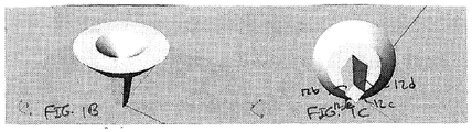
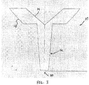
- FIGS 1 A, 1B, and 1C schematically depict an optic 10 according to an embodiment of the invention, which includes a light pipe 12, a central reflector 14 and a peripheral reflector 18.
- the light pipe 12 extends between a proximal end (PE) to a distal end (DE) about an optical axis (OA).
- the light pipe 12 can have a variety of different cross-sectional shapes.
- the light pipe 12 has a polygonal cross-sectional shape (in a plane perpendicular to the optical axis (OA)), such as, square, rectangle, hexagonal, etc.
- the cross-sectional area of the light pipe at its distal end can be greater than the cross-sectional area at its proximal end.
- the light pipe exhibits a progressively increasing cross-sectional area from its proximal end to its distal end.
- the cross-sectional area of the light pipe can be constant from its proximal end to its distal end.
- the light pipe is adapted to receive at its proximal end, via an input surface 12a, light from one or more light sources 20 that are optically coupled thereto.
- the light source 20 can be a single light emitting diode (LED), a plurality of discrete light emitting diodes, a multi-LED chip, among others.
- LED light emitting diode
- the light source 20 can be a single light emitting diode (LED), a plurality of discrete light emitting diodes, a multi-LED chip, among others.
- the light pipe is configured, in a manner known in the art, so that the light rays incident on its lateral surfaces undergo total internal reflection (TIR).
- TIR total internal reflection
- the refractive index of the material forming the light pipe and the shapes of the lateral surfaces of the light pipe are chosen such that many, and preferably all, of the light rays incident on those surfaces, as they propagate along the light pipe, would undergo TIR.
- the lateral surfaces can be metalized to allow specular reflection of the incident light rays.
- the reflection of the light rays incident on the lateral surfaces of the light pipe can be achieved via a combination of specular and total internal reflection.
- the multiple reflection of the light rays by lateral surfaces of the light pipe causes the mixing of those rays.
- Such mixing of the light rays can be advantageous in a variety of lighting applications. For example, in certain applications in which a single light source is employed, such mixing of the light rays can improve intensity homogeneity in a plane perpendicular to the direction of propagation. In certain applications in which light sources of different colors are employed, such mixing of the light rays can provide enhanced color mixing.
- the central reflector 14 is optically coupled to the distal end of the light pipe to receive at least a portion of the light transmitted through the light pipe.
- the central reflector 14 is in the form of an inverted conical reflective surface 14a whose apex 14b is disposed on the optical axis (OA).
- the reflective surface 14a is configured, in a manner known in the art, to reflect via TIR the light rays incident thereon via transmission through the light pipe 12.
- the refractive index of the material forming the optic as well as the shape and configuration of the reflective surface 14b, e.g., the opening angle ⁇ , can be selected such that the incident light rays, or at least a substantial portion thereof (e.g., at least about 80% or 90%), would reflect via TIR by the reflective surface 14a.
- the reflective surface 14a can include a metallic coating to effect specular reflection of the incident light rays.
- the reflective surface 14a redirects the incident light rays to the peripheral reflector 18, which includes a peripheral reflective surface 18a that is configured to receive a portion of the light reflected by the reflective surface 14a and another reflective surface 18b positioned at an angle relative to the peripheral reflective surface 18a, which is configured to receive another portion of the light reflected by the reflective surface 14a.
- the reflective surface 18b is a substantially flat surface that is positioned perpendicularly relative to the optical axis (OA).
- the reflective surfaces 18a and 18b redirect the incident light rays, via reflection, to an output surface 22 through which the light rays exit the optic.
- the reflective surface 14a is also herein referred to in some cases as a fold mirror as a way of indicating that it redirects the light rays leaving the light pipe away from their propagation direction as they exit the light pipe).
- the optic 12 can be configured such that a substantial portion of light exiting the output surface 22 exhibits a narrow beam angle.
- the surfaces 18a and 18b can be configured to redirect a substantial portion of the incident light rays towards the output surfaces 22 in a direction that is substantially parallel to the optical axis. In this manner, the peripheral reflector 18 can collimate the light received from the central reflector 14 for exiting the optic through the output surface 22.
- the optic 12 can be configured such that the light exiting each output surface 22 can exhibit FWHM at less than about 15 degrees, less than about 10 degrees, or less than about 5 degrees.
- the reflective surfaces 18a and 18b are configured to reflect the incident light, or at least a substantial portion thereof (e.g., more than about 80%, or 90%), via TIR.
- a thin metal coating (not shown) can cover at least a portion of the surfaces 18a and 18b to effect specular reflection of the light rays at those surfaces.
- the output surface 22 is substantially flat.
- the output surface can be textured and/or include a plurality of microlenses, e.g., to cause additional mixing of the light rays as they exit the optic therethrough.
- FIG. 2 schematically depicts such an embodiment in which the output surface 22 comprises a plurality of microlenses 24.
- the microlenses can improve color mixing. Further, the microlenses can be employed to achieve greater output beam angles or create an elliptical output beam.
- the optic 10 can receive light at its proximal end from the light source 20.
- the received light is transmitted through the light pipe 12 and is reflected by the central reflector 14 to the peripheral reflector 18, which in turn redirects the light as a collimated set of rays toward the output surface 22 for exiting the optic.
- the light pipe 12 homogenizes the light output of the source 20, e.g., an LED array, while the central reflector 14 and the peripheral collimating reflector 18 form the beam shape.
- the central reflector 14 and peripheral reflector 18 can be configured such that the light exiting each output surface 22 can exhibit FWHM at less than about 15 degrees, less than about 10 degrees, or less than about 5 degrees.
- the optic 10 can be made in a variety of different sizes, shapes and aspect ratios, e.g., based on a particular lighting application for which the optic is intended.
- the sizes of the input and the output surfaces 12a and 22, the length of the light pipe, the lengths and the diameters of the central and the peripheral reflectors as well as the profiles of their reflective surfaces can be adjusted, e.g., based on an application for which the optic is intended.
- the ratio of the length (L) of the light pipe relative to the diameter (D input ) of the its input surface can be in a range of about 3:1 to about 1:1.
- the ratio of the diameter (D output ) of the output surface 22 of the optic relative to D input can be selected, e.g., at least partially based on the desired level of collimation of the light rays exiting the optic. For example, in some embodiments in which a collimation characterized by a divergence of less than about 10 degrees is desired, the ratio of D output relative to D input can be in a range of about 10:1 to about 20:1.
- the optic 10 is fabricated as a single integral unit.
- materials and manufacturing techniques can be employed to form the optic 10.
- suitable materials include, without limitation, PMMA, polycarbonate, glass, silicon, and any optically clear material.
- suitable manufacturing techniques include, without limitation, injection molding. While in many embodiments different parts of the optic are formed of the same material, in other embodiments different materials may be used to form different parts of the optic. For example, one material can be employed to form the light pipe while another material is used to form the remainder of the optic.
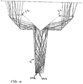
- FIG. 4 schematically depicts that the optic 10 can be employed with multiple light sources (in this embodiments two light sources 24a and 24b) to mix the light emitted by those sources and direct the mixed light as a substantially collimated beam out of the optic.
- the light sources 24a and 24b generate light of different colors.
- the passage of the light rays emitted by the sources 24a and 24b through the light pipe 12 causes their mixing (in this illustration, the light rays associated with one source are shown by solid lines while the light rays associated with the other source are shown by broken lines).
- the central and the peripheral reflectors redirect the mixed light transmitted through the light pipe out of the optic, via the output surface 22, as a substantially collimated beam. In this manner, the optic 10 can be utilized for color mixing applications, among others.
- the central reflector of the optic 10 discussed above can have an undulating reflective surface.
- such an optic 10' can include a central oscillating reflective surface 12'a (the remainder of the optic in this example is identical to the optic 10 discussed above).
- the oscillations of the reflective surface 12' can cause further mixing of the light rays reflected thereby.
- additional mixing of the light rays can improve color mixing in lighting applications.
- FIG. 6 schematically depicts an optic 100 (herein also referred to as an optical system) that includes two optical components 102 and 104 that are optically coupled to one another.
- the optical component 102 is a light pipe that extends about an optical axis (OA) from a proximal end (PE) to a distal end (DE).
- the light pipe is configured to receive light from one or more light sources at its input surface 102a and to transmit the received light to its output surface 102b.
- the light pipe 102 exhibits a progressively increasing cross-sectional area from its input surface to its output surface (in another embodiment, the light pipe can have a substantially constant cross-sectional area).
- the optical component 104 receives, via a central portion 106a of its surface 106, the light exiting the light pipe (at least a portion of this light).
- a central reflective surface 108 which is in the form of an inverted conical surface, directs a portion of the light incident thereon, via reflection, to a lateral reflective surface 110, and another portion of the incident light to a peripheral portion 106b of the surface 106.
- the lateral reflective surface 110 reflects the light incident thereon, via TIR, specular reflection or a combination of the two, to an output surface 112 for exiting the optic.
- a portion of the light reflected by the peripheral portion 106b e.g., via TIR, specular reflection or both
- reaches the output surface 112 directly and another portion of such reflected light reaches the output surface 112 via reflection at the lateral reflective surface 110.
- the output surface 102(b) of the light pipe can comprise a textured surface and/or a plurality of micro lenses.
- the central portion 106a of the surface 106 of the optical element 104 and/or the output surface 112 thereof can comprise a textured surface and/or a plurality of microlenses. As noted above, this can improve mixing of the light rays. The improvement in light mixing can be advantageous in a variety of applications, such as color mixing. By way of example, FIG.
- FIG. 7 schematically depicts an optic 100' according to such an embodiment in which an output surface 102'b of the light pipe, a central portion 106'a of the optical element 104' and an output surface 112' of the optic comprise, respectively, a plurality of microlenses 114, 116, 118.
Landscapes
- Engineering & Computer Science (AREA)
- Physics & Mathematics (AREA)
- General Engineering & Computer Science (AREA)
- Optics & Photonics (AREA)
- General Physics & Mathematics (AREA)
- Microelectronics & Electronic Packaging (AREA)
- Planar Illumination Modules (AREA)
Claims (15)
- Optik (10, 100), umfassend:einen Lichtleiter (12, 102), der sich von einem proximalen Ende (PE) zu einem distalen Ende (DE) um eine optische Achse (OA) erstreckt, wobei der Lichtleiter (12, 102) dazu ausgebildet ist, an seinem proximalen Ende (PE) wenigstens einen Teil des von einer Lichtquelle (20) emittierten Lichtes zu empfangen und eine polygonale Querschnittsform aufzuweisen, um wenigstens einen Teil des empfangenen Lichtes zu mischen, wenn sich das Licht von dem proximalen Ende zu dem distalen Ende fortpflanzt,einen Zentralreflektor (14) mit einer reflektierenden Oberfläche (14a) mit einer invertierten konischen Form und optisch mit dem distalen Ende (DE) des Lichtleiters (12, 102) gekoppelt, um wenigstens einen Teil des durch den Lichtleiter (12, 102) gelangten Lichtes zu empfangen und das empfangene Licht zu reflektieren,einen Randreflektor (18), der optisch mit dem Zentralreflektor (14) zum Empfangen wenigstens eines Teils des reflektierten Lichtes gekoppelt ist,gekennzeichnet durcheine Ausgangsoberfläche (22), undwobei der Randreflektor (18) dazu ausgebildet ist, wenigstens einen Teil des von dem Zentralreflektor (14) empfangenen Lichtes zu der Ausgangsoberfläche (22) umzulenken, und zwar für einen Austritt aus der Optik,und wobei der Randreflektor (18) eine seitliche reflektive Oberfläche (18a) und eine zusätzliche reflektive Oberfläche (18b) umfasst, die mit Bezug zu der seitlichen reflektiven Oberfläche (18a) in einem Winkel angeordnet ist, so dass wenigstens ein Teil des von dem Zentralreflektor (14) reflektierten Lichtes durch die zusätzliche reflektive Oberfläche (18b) zu der seitlichen reflektiven Oberfläche (18a) umgelenkt wird, um von der seitlichen reflektiven Oberfläche (18a) hin zu der Ausgangsoberfläche (22) für einen Austritt aus der Optik reflektiert zu werden.
- Optik nach Anspruch 1, wobei die reflektierende Oberfläche (14a) des Zentralreflektors (14) eine Mehrzahl von Welligkeiten aufweist.
- Optik nach Anspruch 1, wobei der Zentralreflektor (14) dazu ausgebildet ist, wenigstens einen Teil des von dem Lichtleiter (12, 102) empfangenen Lichtes über totale innere Reflexion (TIR) zu reflektieren.
- Optik nach Anspruch 1, wobei die seitliche Oberfläche dazu ausgebildet ist, wenigstens einen Teil des von dem Zentralreflektor reflektierten Lichts zu empfangen und das empfangene Licht für einen Austritt aus der Optik zu der Ausgangsoberfläche umzuleiten.
- Optik nach Anspruch 4, wobei die seitliche Oberfläche (18a) des Randreflektors (18) dazu ausgebildet ist, das empfangene Licht über TIR zu der Ausgangsoberfläche (22) umzuleiten.
- Optik nach Anspruch 5, wobei die seitliche Oberfläche (18a) des Randreflektors (18) dazu ausgebildet ist, das empfangene Licht entlang einer Richtung im Wesentlichen parallel zu der optischen Achse (OA) umzuleiten.
- Optik nach Anspruch 4, wobei die zusätzliche Oberfläche, welche relativ zu der seitlichen Oberfläche in einem Winkel angeordnet ist, derart angeordnet ist, um einen anderen Teil des Lichtes, der von dem Zentralreflektor reflektiert worden ist, zu empfangen, um den Teil des Lichtes zu der Ausgangsoberfläche umzuleiten.
- Optik nach Anspruch 7, wobei die zusätzliche reflektive Oberfläche (18b), die mit Bezug auf die seitliche Oberfläche (18a) in einem Winkel angeordnet ist, dazu ausgebildet ist, wenigstens einen Teil des empfangenen Lichtes über TIR umzulenken.
- Optik nach Anspruch 7, wobei die zusätzliche reflektive Oberfläche (18b), welche mit Bezug auf die seitliche Oberfläche (18a) in einem Winkel angeordnet ist, im Wesentlichen senkrecht zu der optischen Achse (OA) ist.
- Optik nach Anspruch 4, wobei die Ausgangsoberfläche (22) eine Mehrzahl von Mikrolinsen umfasst.
- Optik nach Anspruch 4, wobei wenigstens ein Teil der Ausgangsoberfläche (22) texturiert ist.
- Optik nach Anspruch 1, wobei die Optik als ein einzelnes einheitliches Stück ausgebildet ist.
- Optik nach Anspruch 1, wobei die Optik aus separaten Stücken gebildet ist, welche optisch miteinander gekoppelt sind.
- Optik nach Anspruch 1, wobei die Lichtquelle (20) eine einzelne LED, eine Mehrzahl von LEDs oder einen oder mehrere Multi-LED-Chips umfasst.
- Optik nach Anspruch 1, wobei die Lichtquelle (20) zwei oder mehrere LEDs umfasst, die zum Ausstrahlen von Licht mit unterschiedlichen Farben ausgebildet sind.
Applications Claiming Priority (2)
| Application Number | Priority Date | Filing Date | Title |
|---|---|---|---|
| US201261724130P | 2012-11-08 | 2012-11-08 | |
| PCT/US2013/069184 WO2014074842A1 (en) | 2012-11-08 | 2013-11-08 | Multi-led/multi-chip color mixing optics |
Publications (2)
| Publication Number | Publication Date |
|---|---|
| EP2917636A1 EP2917636A1 (de) | 2015-09-16 |
| EP2917636B1 true EP2917636B1 (de) | 2017-05-17 |
Family
ID=49679612
Family Applications (1)
| Application Number | Title | Priority Date | Filing Date |
|---|---|---|---|
| EP13798442.3A Active EP2917636B1 (de) | 2012-11-08 | 2013-11-08 | Farbmischungsoptik mit mehreren leds/chips |
Country Status (3)
| Country | Link |
|---|---|
| US (2) | US9746596B2 (de) |
| EP (1) | EP2917636B1 (de) |
| WO (1) | WO2014074842A1 (de) |
Families Citing this family (14)
| Publication number | Priority date | Publication date | Assignee | Title |
|---|---|---|---|---|
| US9746596B2 (en) | 2012-11-08 | 2017-08-29 | Fraen Corporation | Multi-LED/multi-chip color mixing optics |
| US10422944B2 (en) * | 2013-01-30 | 2019-09-24 | Ideal Industries Lighting Llc | Multi-stage optical waveguide for a luminaire |
| FR3023902B1 (fr) * | 2014-07-16 | 2019-06-14 | Valeo Systemes Thermiques | Dispositif lumineux |
| US9933122B2 (en) * | 2014-09-30 | 2018-04-03 | Koehler-Bright Star LLC | Lighting device with central and peripheral illumination |
| WO2016073937A1 (en) | 2014-11-07 | 2016-05-12 | Quarkstar Llc | Troffer luminaire |
| WO2016094666A1 (en) * | 2014-12-10 | 2016-06-16 | Fraen Corporation | Mirror for solar-sky pipe collector |
| DE102015101413B4 (de) | 2015-01-30 | 2020-03-26 | Fraunhofer-Gesellschaft zur Förderung der angewandten Forschung e.V. | Leuchtmittel mit veränderbarer Emission und Verfahren zum gesteuerten Verändern des Farbeindrucks einer Lichtquelle |
| US9638392B2 (en) | 2015-09-25 | 2017-05-02 | Osram Sylvania Inc. | Lamp optic for use in LED-based lamp |
| DE102016204181A1 (de) * | 2016-03-15 | 2017-09-21 | Osram Gmbh | Retrofit-Lampe und Fahrzeugscheinwerfer mit Retrofit-Lampe |
| WO2019022972A1 (en) * | 2017-07-28 | 2019-01-31 | Fraen Corporation | MULTI-LED / MULTI-CHIP COLOR MIXING OPTICAL |
| CN109479554B (zh) * | 2017-09-08 | 2021-10-12 | 松下知识产权经营株式会社 | 植物栽培装置 |
| US11162663B2 (en) | 2018-10-02 | 2021-11-02 | Electronic Theatre Controls, Inc. | Lighting fixture |
| JP6690845B1 (ja) | 2019-03-26 | 2020-04-28 | Necプラットフォームズ株式会社 | Led光源機構、電話機およびled光源形成方法 |
| US10845030B1 (en) | 2020-02-26 | 2020-11-24 | Electronic Theatre Controls, Inc. | Lighting fixture with internal shutter blade |
Family Cites Families (21)
| Publication number | Priority date | Publication date | Assignee | Title |
|---|---|---|---|---|
| JPH08321918A (ja) * | 1995-03-22 | 1996-12-03 | Canon Inc | 導光体、該導光体を有する照明装置及び該照明装置を有する情報処理装置 |
| DE19547861A1 (de) * | 1995-12-21 | 1997-06-26 | Reitter & Schefenacker Gmbh | Rückleuchte für Fahrzeuge, vorzugsweise Kraftfahrzeuge |
| BR9811170A (pt) * | 1997-08-12 | 2000-07-25 | Decoma Int Inc | Conjunto de lente bi-reflexiva e conjunto emissor de luz para utilização em um veìculo |
| DE19739173A1 (de) * | 1997-09-06 | 1999-03-11 | Hella Kg Hueck & Co | Signalleuchte für Fahrzeuge |
| FR2846400B1 (fr) | 2002-10-28 | 2005-10-07 | Valeo Vision | Feu de signalisation comportant un dispositif de recuperation et de repartition du flux lumineux vers un reflecteur annulaire |
| TWI282017B (en) * | 2004-05-28 | 2007-06-01 | Epistar Corp | Planar light device |
| US8704149B2 (en) * | 2004-09-24 | 2014-04-22 | Epistar Corporation | Optoelectronic device assembly having auxiliary energy receiver |
| DE102005003367B4 (de) * | 2005-01-24 | 2009-05-07 | Odelo Gmbh | Leuchteinheit mit Lichtteiler |
| US7489453B2 (en) * | 2005-11-15 | 2009-02-10 | Visteon Global Technologies, Inc. | Side emitting near field lens |
| CN101346583B (zh) * | 2005-12-27 | 2011-11-23 | 昭和电工株式会社 | 光导部件、平坦光源装置和显示装置 |
| WO2008080165A2 (en) | 2006-12-22 | 2008-07-03 | Lighting Science Group Corporation | Multi-primary led collimation optic assemblies |
| CN101359122B (zh) * | 2007-08-03 | 2011-05-04 | 清华大学 | 背光模组 |
| US8256931B2 (en) | 2008-07-24 | 2012-09-04 | Seward George H | Achromatic homogenizer and collimator for LEDs |
| JP5540018B2 (ja) | 2009-02-03 | 2014-07-02 | フレーン・コーポレーシヨン | 光混合光学装置および光混合系 |
| CZ309346B6 (cs) * | 2010-11-01 | 2022-09-14 | Varroc Lighting Systems, s.r.o. | Světlovodný modul se seřiditelným osvětlením povrchu obrysu |
| JP5553643B2 (ja) * | 2010-02-24 | 2014-07-16 | スタンレー電気株式会社 | 車両用灯具 |
| US8956032B2 (en) | 2010-09-17 | 2015-02-17 | Invisua Holding B.V. | LED lighting system comprising an optical system suitable for providing a light beam |
| US20130258699A1 (en) * | 2012-02-06 | 2013-10-03 | Lumenetix, Inc. | System and method for mixing light emitted from an array having different color light emitting diodes |
| US9146016B2 (en) | 2012-03-29 | 2015-09-29 | Fraen Corporation | Tiling of multiple polygons for micro-lens array |
| WO2013166376A1 (en) * | 2012-05-04 | 2013-11-07 | Excelitas Technologies Corp. | Color temperature tunable led-based lamp module |
| US9746596B2 (en) | 2012-11-08 | 2017-08-29 | Fraen Corporation | Multi-LED/multi-chip color mixing optics |
-
2013
- 2013-11-08 US US14/441,691 patent/US9746596B2/en active Active
- 2013-11-08 WO PCT/US2013/069184 patent/WO2014074842A1/en active Application Filing
- 2013-11-08 EP EP13798442.3A patent/EP2917636B1/de active Active
-
2017
- 2017-07-28 US US15/663,504 patent/US10429565B2/en active Active
Also Published As
| Publication number | Publication date |
|---|---|
| US9746596B2 (en) | 2017-08-29 |
| US20150285980A1 (en) | 2015-10-08 |
| EP2917636A1 (de) | 2015-09-16 |
| US20170357046A1 (en) | 2017-12-14 |
| WO2014074842A1 (en) | 2014-05-15 |
| US10429565B2 (en) | 2019-10-01 |
Similar Documents
| Publication | Publication Date | Title |
|---|---|---|
| US10429565B2 (en) | Multi-LED/multi-chip color mixing optics | |
| US10203446B2 (en) | Light guide illumination device with light divergence modifier | |
| EP2334980B1 (de) | Kompaktes optisches system und linsen zur erzeugung von gleichförmigem kollimiertem licht | |
| US8231256B1 (en) | Light fixture comprising a multi-functional non-imaging optical component | |
| US10180521B2 (en) | Luminaire for emitting directional and nondirectional light | |
| EP2656123B1 (de) | Optischer lichtmischer zur bereitstellung eines homogenen und gleichmässigen lichtstrahls | |
| US20100046219A1 (en) | Light guide and light-output device | |
| US10520663B2 (en) | Illumination system based on active and passive illumination devices | |
| US8376575B1 (en) | Light emitting diode optical system and related methods | |
| US9803808B2 (en) | Optic holder with integrated light premixer | |
| US11553566B2 (en) | Luminaire for emitting directional and non-directional light | |
| US20190094443A1 (en) | Multi-LED/Multi-Chip Color Mixing Optics | |
| US11899219B2 (en) | Low-profile color-mixing lightpipe | |
| US11867365B2 (en) | Luminaire for emitting directional and non-directional light |
Legal Events
| Date | Code | Title | Description |
|---|---|---|---|
| PUAI | Public reference made under article 153(3) epc to a published international application that has entered the european phase |
Free format text: ORIGINAL CODE: 0009012 |
|
| 17P | Request for examination filed |
Effective date: 20150605 |
|
| AK | Designated contracting states |
Kind code of ref document: A1 Designated state(s): AL AT BE BG CH CY CZ DE DK EE ES FI FR GB GR HR HU IE IS IT LI LT LU LV MC MK MT NL NO PL PT RO RS SE SI SK SM TR |
|
| AX | Request for extension of the european patent |
Extension state: BA ME |
|
| DAX | Request for extension of the european patent (deleted) | ||
| RIN1 | Information on inventor provided before grant (corrected) |
Inventor name: PRESTON, JAMES Inventor name: ZOLLERS, MICHAEL Inventor name: HOUSAND, BRIEN J. |
|
| GRAP | Despatch of communication of intention to grant a patent |
Free format text: ORIGINAL CODE: EPIDOSNIGR1 |
|
| INTG | Intention to grant announced |
Effective date: 20161208 |
|
| GRAS | Grant fee paid |
Free format text: ORIGINAL CODE: EPIDOSNIGR3 |
|
| GRAA | (expected) grant |
Free format text: ORIGINAL CODE: 0009210 |
|
| AK | Designated contracting states |
Kind code of ref document: B1 Designated state(s): AL AT BE BG CH CY CZ DE DK EE ES FI FR GB GR HR HU IE IS IT LI LT LU LV MC MK MT NL NO PL PT RO RS SE SI SK SM TR |
|
| REG | Reference to a national code |
Ref country code: GB Ref legal event code: FG4D |
|
| REG | Reference to a national code |
Ref country code: CH Ref legal event code: EP |
|
| REG | Reference to a national code |
Ref country code: IE Ref legal event code: FG4D |
|
| REG | Reference to a national code |
Ref country code: AT Ref legal event code: REF Ref document number: 894804 Country of ref document: AT Kind code of ref document: T Effective date: 20170615 |
|
| REG | Reference to a national code |
Ref country code: DE Ref legal event code: R096 Ref document number: 602013021358 Country of ref document: DE |
|
| REG | Reference to a national code |
Ref country code: NL Ref legal event code: MP Effective date: 20170517 |
|
| REG | Reference to a national code |
Ref country code: LT Ref legal event code: MG4D |
|
| REG | Reference to a national code |
Ref country code: AT Ref legal event code: MK05 Ref document number: 894804 Country of ref document: AT Kind code of ref document: T Effective date: 20170517 |
|
| PG25 | Lapsed in a contracting state [announced via postgrant information from national office to epo] |
Ref country code: GR Free format text: LAPSE BECAUSE OF FAILURE TO SUBMIT A TRANSLATION OF THE DESCRIPTION OR TO PAY THE FEE WITHIN THE PRESCRIBED TIME-LIMIT Effective date: 20170818 Ref country code: AT Free format text: LAPSE BECAUSE OF FAILURE TO SUBMIT A TRANSLATION OF THE DESCRIPTION OR TO PAY THE FEE WITHIN THE PRESCRIBED TIME-LIMIT Effective date: 20170517 Ref country code: LT Free format text: LAPSE BECAUSE OF FAILURE TO SUBMIT A TRANSLATION OF THE DESCRIPTION OR TO PAY THE FEE WITHIN THE PRESCRIBED TIME-LIMIT Effective date: 20170517 Ref country code: ES Free format text: LAPSE BECAUSE OF FAILURE TO SUBMIT A TRANSLATION OF THE DESCRIPTION OR TO PAY THE FEE WITHIN THE PRESCRIBED TIME-LIMIT Effective date: 20170517 Ref country code: NO Free format text: LAPSE BECAUSE OF FAILURE TO SUBMIT A TRANSLATION OF THE DESCRIPTION OR TO PAY THE FEE WITHIN THE PRESCRIBED TIME-LIMIT Effective date: 20170817 Ref country code: HR Free format text: LAPSE BECAUSE OF FAILURE TO SUBMIT A TRANSLATION OF THE DESCRIPTION OR TO PAY THE FEE WITHIN THE PRESCRIBED TIME-LIMIT Effective date: 20170517 |
|
| REG | Reference to a national code |
Ref country code: FR Ref legal event code: PLFP Year of fee payment: 5 |
|
| PG25 | Lapsed in a contracting state [announced via postgrant information from national office to epo] |
Ref country code: RS Free format text: LAPSE BECAUSE OF FAILURE TO SUBMIT A TRANSLATION OF THE DESCRIPTION OR TO PAY THE FEE WITHIN THE PRESCRIBED TIME-LIMIT Effective date: 20170517 Ref country code: LV Free format text: LAPSE BECAUSE OF FAILURE TO SUBMIT A TRANSLATION OF THE DESCRIPTION OR TO PAY THE FEE WITHIN THE PRESCRIBED TIME-LIMIT Effective date: 20170517 Ref country code: NL Free format text: LAPSE BECAUSE OF FAILURE TO SUBMIT A TRANSLATION OF THE DESCRIPTION OR TO PAY THE FEE WITHIN THE PRESCRIBED TIME-LIMIT Effective date: 20170517 Ref country code: IS Free format text: LAPSE BECAUSE OF FAILURE TO SUBMIT A TRANSLATION OF THE DESCRIPTION OR TO PAY THE FEE WITHIN THE PRESCRIBED TIME-LIMIT Effective date: 20170917 Ref country code: PL Free format text: LAPSE BECAUSE OF FAILURE TO SUBMIT A TRANSLATION OF THE DESCRIPTION OR TO PAY THE FEE WITHIN THE PRESCRIBED TIME-LIMIT Effective date: 20170517 Ref country code: SE Free format text: LAPSE BECAUSE OF FAILURE TO SUBMIT A TRANSLATION OF THE DESCRIPTION OR TO PAY THE FEE WITHIN THE PRESCRIBED TIME-LIMIT Effective date: 20170517 Ref country code: BG Free format text: LAPSE BECAUSE OF FAILURE TO SUBMIT A TRANSLATION OF THE DESCRIPTION OR TO PAY THE FEE WITHIN THE PRESCRIBED TIME-LIMIT Effective date: 20170817 |
|
| PG25 | Lapsed in a contracting state [announced via postgrant information from national office to epo] |
Ref country code: CZ Free format text: LAPSE BECAUSE OF FAILURE TO SUBMIT A TRANSLATION OF THE DESCRIPTION OR TO PAY THE FEE WITHIN THE PRESCRIBED TIME-LIMIT Effective date: 20170517 Ref country code: SK Free format text: LAPSE BECAUSE OF FAILURE TO SUBMIT A TRANSLATION OF THE DESCRIPTION OR TO PAY THE FEE WITHIN THE PRESCRIBED TIME-LIMIT Effective date: 20170517 Ref country code: EE Free format text: LAPSE BECAUSE OF FAILURE TO SUBMIT A TRANSLATION OF THE DESCRIPTION OR TO PAY THE FEE WITHIN THE PRESCRIBED TIME-LIMIT Effective date: 20170517 Ref country code: RO Free format text: LAPSE BECAUSE OF FAILURE TO SUBMIT A TRANSLATION OF THE DESCRIPTION OR TO PAY THE FEE WITHIN THE PRESCRIBED TIME-LIMIT Effective date: 20170517 Ref country code: DK Free format text: LAPSE BECAUSE OF FAILURE TO SUBMIT A TRANSLATION OF THE DESCRIPTION OR TO PAY THE FEE WITHIN THE PRESCRIBED TIME-LIMIT Effective date: 20170517 |
|
| REG | Reference to a national code |
Ref country code: DE Ref legal event code: R097 Ref document number: 602013021358 Country of ref document: DE |
|
| PG25 | Lapsed in a contracting state [announced via postgrant information from national office to epo] |
Ref country code: SM Free format text: LAPSE BECAUSE OF FAILURE TO SUBMIT A TRANSLATION OF THE DESCRIPTION OR TO PAY THE FEE WITHIN THE PRESCRIBED TIME-LIMIT Effective date: 20170517 |
|
| PLBE | No opposition filed within time limit |
Free format text: ORIGINAL CODE: 0009261 |
|
| STAA | Information on the status of an ep patent application or granted ep patent |
Free format text: STATUS: NO OPPOSITION FILED WITHIN TIME LIMIT |
|
| 26N | No opposition filed |
Effective date: 20180220 |
|
| PG25 | Lapsed in a contracting state [announced via postgrant information from national office to epo] |
Ref country code: SI Free format text: LAPSE BECAUSE OF FAILURE TO SUBMIT A TRANSLATION OF THE DESCRIPTION OR TO PAY THE FEE WITHIN THE PRESCRIBED TIME-LIMIT Effective date: 20170517 |
|
| PG25 | Lapsed in a contracting state [announced via postgrant information from national office to epo] |
Ref country code: MC Free format text: LAPSE BECAUSE OF FAILURE TO SUBMIT A TRANSLATION OF THE DESCRIPTION OR TO PAY THE FEE WITHIN THE PRESCRIBED TIME-LIMIT Effective date: 20170517 |
|
| PG25 | Lapsed in a contracting state [announced via postgrant information from national office to epo] |
Ref country code: LI Free format text: LAPSE BECAUSE OF NON-PAYMENT OF DUE FEES Effective date: 20171130 Ref country code: CH Free format text: LAPSE BECAUSE OF NON-PAYMENT OF DUE FEES Effective date: 20171130 |
|
| PG25 | Lapsed in a contracting state [announced via postgrant information from national office to epo] |
Ref country code: LU Free format text: LAPSE BECAUSE OF NON-PAYMENT OF DUE FEES Effective date: 20171108 |
|
| REG | Reference to a national code |
Ref country code: BE Ref legal event code: MM Effective date: 20171130 |
|
| REG | Reference to a national code |
Ref country code: IE Ref legal event code: MM4A |
|
| PG25 | Lapsed in a contracting state [announced via postgrant information from national office to epo] |
Ref country code: MT Free format text: LAPSE BECAUSE OF NON-PAYMENT OF DUE FEES Effective date: 20171108 |
|
| PG25 | Lapsed in a contracting state [announced via postgrant information from national office to epo] |
Ref country code: IE Free format text: LAPSE BECAUSE OF NON-PAYMENT OF DUE FEES Effective date: 20171108 |
|
| PG25 | Lapsed in a contracting state [announced via postgrant information from national office to epo] |
Ref country code: BE Free format text: LAPSE BECAUSE OF NON-PAYMENT OF DUE FEES Effective date: 20171130 |
|
| PGFP | Annual fee paid to national office [announced via postgrant information from national office to epo] |
Ref country code: DE Payment date: 20181128 Year of fee payment: 6 Ref country code: FI Payment date: 20181128 Year of fee payment: 6 |
|
| PGFP | Annual fee paid to national office [announced via postgrant information from national office to epo] |
Ref country code: CH Payment date: 20181219 Year of fee payment: 6 Ref country code: FR Payment date: 20181127 Year of fee payment: 6 |
|
| PG25 | Lapsed in a contracting state [announced via postgrant information from national office to epo] |
Ref country code: HU Free format text: LAPSE BECAUSE OF FAILURE TO SUBMIT A TRANSLATION OF THE DESCRIPTION OR TO PAY THE FEE WITHIN THE PRESCRIBED TIME-LIMIT; INVALID AB INITIO Effective date: 20131108 |
|
| PG25 | Lapsed in a contracting state [announced via postgrant information from national office to epo] |
Ref country code: CY Free format text: LAPSE BECAUSE OF FAILURE TO SUBMIT A TRANSLATION OF THE DESCRIPTION OR TO PAY THE FEE WITHIN THE PRESCRIBED TIME-LIMIT Effective date: 20170517 |
|
| PG25 | Lapsed in a contracting state [announced via postgrant information from national office to epo] |
Ref country code: MK Free format text: LAPSE BECAUSE OF FAILURE TO SUBMIT A TRANSLATION OF THE DESCRIPTION OR TO PAY THE FEE WITHIN THE PRESCRIBED TIME-LIMIT Effective date: 20170517 |
|
| PG25 | Lapsed in a contracting state [announced via postgrant information from national office to epo] |
Ref country code: TR Free format text: LAPSE BECAUSE OF FAILURE TO SUBMIT A TRANSLATION OF THE DESCRIPTION OR TO PAY THE FEE WITHIN THE PRESCRIBED TIME-LIMIT Effective date: 20170517 |
|
| PG25 | Lapsed in a contracting state [announced via postgrant information from national office to epo] |
Ref country code: PT Free format text: LAPSE BECAUSE OF FAILURE TO SUBMIT A TRANSLATION OF THE DESCRIPTION OR TO PAY THE FEE WITHIN THE PRESCRIBED TIME-LIMIT Effective date: 20170517 |
|
| REG | Reference to a national code |
Ref country code: DE Ref legal event code: R119 Ref document number: 602013021358 Country of ref document: DE |
|
| REG | Reference to a national code |
Ref country code: FI Ref legal event code: MAE |
|
| PG25 | Lapsed in a contracting state [announced via postgrant information from national office to epo] |
Ref country code: FI Free format text: LAPSE BECAUSE OF NON-PAYMENT OF DUE FEES Effective date: 20191108 Ref country code: AL Free format text: LAPSE BECAUSE OF FAILURE TO SUBMIT A TRANSLATION OF THE DESCRIPTION OR TO PAY THE FEE WITHIN THE PRESCRIBED TIME-LIMIT Effective date: 20170517 |
|
| GBPC | Gb: european patent ceased through non-payment of renewal fee |
Effective date: 20191108 |
|
| PG25 | Lapsed in a contracting state [announced via postgrant information from national office to epo] |
Ref country code: FR Free format text: LAPSE BECAUSE OF NON-PAYMENT OF DUE FEES Effective date: 20191130 Ref country code: GB Free format text: LAPSE BECAUSE OF NON-PAYMENT OF DUE FEES Effective date: 20191108 Ref country code: DE Free format text: LAPSE BECAUSE OF NON-PAYMENT OF DUE FEES Effective date: 20200603 |
|
| PGFP | Annual fee paid to national office [announced via postgrant information from national office to epo] |
Ref country code: IT Payment date: 20231122 Year of fee payment: 11 |