EP2917481B1 - Elektromagnetische telemetrievorrichtung für bohrlöcher - Google Patents
Elektromagnetische telemetrievorrichtung für bohrlöcher Download PDFInfo
- Publication number
- EP2917481B1 EP2917481B1 EP13854109.9A EP13854109A EP2917481B1 EP 2917481 B1 EP2917481 B1 EP 2917481B1 EP 13854109 A EP13854109 A EP 13854109A EP 2917481 B1 EP2917481 B1 EP 2917481B1
- Authority
- EP
- European Patent Office
- Prior art keywords
- electrically
- probe
- gap sub
- insulating layer
- bore
- Prior art date
- Legal status (The legal status is an assumption and is not a legal conclusion. Google has not performed a legal analysis and makes no representation as to the accuracy of the status listed.)
- Active
Links
Images



Classifications
-
- E—FIXED CONSTRUCTIONS
- E21—EARTH OR ROCK DRILLING; MINING
- E21B—EARTH OR ROCK DRILLING; OBTAINING OIL, GAS, WATER, SOLUBLE OR MELTABLE MATERIALS OR A SLURRY OF MINERALS FROM WELLS
- E21B17/00—Drilling rods or pipes; Flexible drill strings; Kellies; Drill collars; Sucker rods; Cables; Casings; Tubings
- E21B17/003—Drilling rods or pipes; Flexible drill strings; Kellies; Drill collars; Sucker rods; Cables; Casings; Tubings with electrically conducting or insulating means
-
- E—FIXED CONSTRUCTIONS
- E21—EARTH OR ROCK DRILLING; MINING
- E21B—EARTH OR ROCK DRILLING; OBTAINING OIL, GAS, WATER, SOLUBLE OR MELTABLE MATERIALS OR A SLURRY OF MINERALS FROM WELLS
- E21B47/00—Survey of boreholes or wells
- E21B47/01—Devices for supporting measuring instruments on drill bits, pipes, rods or wirelines; Protecting measuring instruments in boreholes against heat, shock, pressure or the like
-
- E—FIXED CONSTRUCTIONS
- E21—EARTH OR ROCK DRILLING; MINING
- E21B—EARTH OR ROCK DRILLING; OBTAINING OIL, GAS, WATER, SOLUBLE OR MELTABLE MATERIALS OR A SLURRY OF MINERALS FROM WELLS
- E21B47/00—Survey of boreholes or wells
- E21B47/12—Means for transmitting measuring-signals or control signals from the well to the surface, or from the surface to the well, e.g. for logging while drilling
- E21B47/13—Means for transmitting measuring-signals or control signals from the well to the surface, or from the surface to the well, e.g. for logging while drilling by electromagnetic energy, e.g. radio frequency
Definitions
- the present invention relates to a probe for subsurface drilling and a corresponding subsurface drilling method.
- US 2005/0167098 discloses a gap collar for an electromagnetic communication unit of a downhole tool positioned in a wellbore.
- the downhole tool communicates with a surface unit via an electromagnetic field generated by the electromagnetic communication unit.
- the gap collar includes a first collar having a first end connector and a second collar having a second end connector matingly connectable to the first end connector.
- the gap collar further includes a non-conductive insulation coating disposed on the first and/or second end connectors, and a non-conductive insulation molding positioned about an inner and/or outer surface of the collars.
- the insulation molding molding ly conforms to the shape collars.
- the connectors are provided with mated threads modified to receive the insulation coating. Measurements taken by the downhole tool may be stored in memory, and transmitted to the surface unit via the electromagnetic field.
- This application relates lo subsurface drilling, specifically to apparatus for telemetry of information from downhole locations.
- Embodiments are applicable to drilling wells for recovering hydrocarbons.
- Recovering hydrocarbons from subterranean zones relies on the process of drilling wellbores.
- Drilling fluid usually in the form of a drilling "mud" is typically pumped through die drill string. The drilling fluid cools and lubricates the drill bit and also carries cuttings back to the surface. Drilling fluid may also be used to help control bottom hole pressure to inhibit hydrocarbon influx from the formation into the wellbore and potential blow out at surface.
- Bottom hole assembly is the name given to the equipment at the terminal and of a drill string.
- a BHA may comprise elements such as:
- Telemetry information can be invaluable for efficient drilling operations.
- telemetry information may be used by a drill rig crew to make decisions about controlling and steering the drill bit to optimize the drilling speed and trajectory based on numerous factors, including legal boundaries, locations of existing wells, formation properties, hydrocarbon size and location, etc.
- a crew may make intentional deviations from the planned path as necessary based on information gathered from downhole sensors and transmitted to the surface by telemetry during the drilling process. The ability to obtain real time data allows for relatively more economical and more efficient drilling operations.
- Various techniques have been used to transmit information from a location in a bore hole to the surface. These include transmitting information by generating vibrations in fluid in the bore hole (e.g. acoustic telemetry or mud pulse telemetry) and transmitting information by way of electromagnetic signals that propagate at least in part through the earth (EM telemetry).
- EM telemetry electromagnetic signals that propagate at least in part through the earth
- Other telemetry systems use hardwired drill pipe or fibre optic cable to carry data to the surface.
- a typical arrangement for electromagnetic telemetry uses parts of the drill string as an antenna.
- the drill string may be divided into two conductive sections by including an insulating joint or connector (a "gap sub") in the drill string.
- the gap sub is typically placed within a bottom hole assembly such that metallic drill pipe in the drill string above the BHA serves as one antenna element and metallic sections in the BHA serve as another antenna element.
- Electromagnetic telemetry signals can then be transmitted by applying electrical signals between the two antenna elements.
- the signals typically comprise very low frequency AC signals applied in a manner that codes information for transmission to the surface.
- the electromagnetic signals may be detected at the surface, for example by measuring electrical potential differences between the drill string and one or more ground rods.
- a challenge with EM telemetry is that the generated signals are significantly attenuated as they propagate to the surface. Further, the electrical power available to generate EM signals may be provided by batteries or another power source that has limited capacity. Therefore, it is desirable to provide a system in which EM signals are generated efficiently.
- the gap sub is an important factor in an EM telemetry system.
- the gap sub must provide electrical isolation between two parts of the drill string as well as withstand the extreme mechanical loading induced during drilling and the high differential pressures that occur between the center and exterior of the drill pipe.
- Drill string components are typically made from high strength, ductile metal alloys in order to handle the loading without failure.
- Most electrically-insulating materials suitable for electrically isolating different parts of a gap sub are weaker than metals (e.g. rubber, plastic, epoxy) or quite brittle (ceramics). This makes it difficult to design a gap sub that is both configured to provide efficient transmission of EM telemetry signals and has the mechanical properties required of a link in the drill string.
- the invention has several aspects.
- One aspect provides EM telemetry apparatus for downhole applications.
- Another aspect provides methods for subsurface drilling.
- the present invention provides a probe for use in subsurface drilling as defined in independent claim 1.
- the probe comprises an elongated metallic housing.
- the housing encloses electronics, including a telemetry signal generator.
- the housing comprises first and second electrical contacts spaced apart longitudinally on the outside of the housing and an electrically-insulating gap comprising an electrically-insulating material providing electrical isolation between first and second parts of the metallic housing.
- the gap is located between the first and second electrical contacts.
- the probe also comprises an electrically-insulating layer on an outside surface of the metallic housing.
- the electrically insulating layer at least partially covers the electrically-insulating gap and extends continuously to cover an outside surface of the metallic housing on at least one side of the gap. In some embodiments the covering extends for a distance of at least 1 meter.
- the probe is combined with a gap sub.
- the gap sub (which may comprise one component or a plurality of separable components comprises an electrically- conducting uphole part comprising an uphole coupling for coupling into a drill string, an electrically-conducting downhole pan comprising a downhole coupling for coupling into the drill string, a bore extending through the gap sub from the uphole coupling to the downhole coupling and an electrically-insulating gap portion electrically isolating the uphole part of the gap sub from the downhole part of the gap sub.
- the 10 probe is located within the bore of the gap sub and die first electrical contact is in electrical contact with the uphole part of the gap sub and the second electrical contact is in electrical contact with the downhole part of the gap sub.
- a method according to the invention provides a subsurface drilling method performed using a drill string comprising a gap sub and an electronics package located in a bore of the gap sub as defined in independent claim 16.
- the electronics package comprises electrical contacts that are in electrical contact with electrically-conductive parts of the gap sub.
- the method comprises passing a drilling fluid down a bore of the drill string and, at the location of the electronics package, channeling the drilling fluid into a channel that is electrically insulated from both the electrically conductive parts of the gap sub and electrically conductive parts of the housing of the electronics package.
- FIG 1 shows schematically an example drilling operation.
- a drill rig 10 drives a drill string 12 which includes sections of drill pipe that extend to a drill bit 14.
- the illustrated drill rig 10 includes a derrick 10A, a rig floor 10B and draw works 10C for supporting the drill string.
- Drill bit 14 is larger in diameter than the drill string above the drill bit.
- An annular region 15 surrounding the drill string is typically filled with drilling fluid. The drilling fluid is pumped through a bore in the drill string to the drill bit and returns to the surface through annular region 15 carrying cuttings from the drilling operation.
- a casing 16 may be made in the well bore.
- a blow out preventer 17 is supported at a top end of the casing.
- the drill rig illustrated in Figure 1 is an example only. The methods and apparatus described herein are not specific to any particular type of drill rig.
- Drill string 12 includes a gap sub 20.
- An EM signal generator 18 located inside the drill string (for example in an electronics probe contained within the bore of the drill string) is electrically connected across the electrically-insulating gap of the gap sub 20.
- the signals from the EM signal generator result in electrical currents 19A and electric fields 19B that are detectable at the surface.
- a signal receiver 13 is connected by signal cables 13A to measure potential differences between electrical grounding stakes 13B and the top end of drill string 12.
- a display 11 may be connected to display data received by the signal receiver 13.
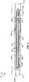
- FIG. 2 shows an example arrangement of a gap sub 20.
- Gap sub 20 has an electrically-conducting uphole portion 20A and an electrically conducting downhole portion 20B separated by gap 20C filled with an electrically-insulating material.
- Couplings 21 for coupling to adjacent elements of the drill string are provided at the uphole and downhole ends of gap sub 20.
- An electronics package 22 comprising an EM telemetry signal generator (not shown in Figure 2 ) is supported in a bore 20D of gap sub 20.
- Electronics package 22 has a metal housing 23 comprising first and second parts 23A and 23B that are electrically insulated from one another by an electrically-insulating gap 23C.
- First and second electrodes 24A and 24B are connected to the telemetry signal generator and are respectively in contact with the uphole portion 20A and the downhole portion 20B of gap sub 20.
- Electrode 24A may be, but is not necessarily, in electrical contact with first part 23A of the housing of electronics package 22.
- Electrode 24B may be, but is not necessarily in electrical contact with second part 23B of the housing of electronics package 22.
- An electrically-insulating layer 25 at least partially covers electrically-insulating gap 23C of electronics package 22. Electrically insulating layer 25 extends over the outside surface of electronics package 22 and continuously covers the outside surface of conductive housing 23 of electronics package 22 for a distance beyond electrically-insulating gap 23C on one or both sides of electrically-insulating gap 23C. In some embodiments the length of continuous coverage of electrically-insulating layer 25 is at least 1 meter and preferably at least 1 1 ⁇ 2 meters or 2 meters. In some example embodiments the length of continuous coverage of electrically-insulating layer 25 is 3 to 4 meters.
- electrically-insulating layer 25 continuously covers at least 60% or 70% or 80% of that portion of the outside surface of electronics package 22 that lies between electrodes 24A and 24B. In some embodiments electrically insulating layer 25 continuously covers substantially all of that portion of the outside surface of electronics package 22 that lies between electrodes 24A and 24B. Here, 'substantially all' means at least 95%.
- electrically-insulating layer 25 comprises a coating applied to electronics package 22, a sleeve or tube extending around electronics package 22, or the like.
- the material of layer 25 may be any electrically insulating material suitable for exposure to downhole conditions. Some non-limiting examples are suitable thermoplastics, epoxies, ceramics, elastomeric polymers, and rubber.
- Layer 25 may comprise a coating that is applied to, or bonded to electronics package 22 or a pre-formed component (formed e.g. by extrusion, injection molding, or the like which is subsequently attached to, affixed around, or supported around electronics package 22.
- the material of layer 25 should be capable of withstanding downhole conditions without degradation.
- the ideal material can withstand temperature of up to at least 150C (preferably 175C or 200C or more), is chemically resistant or inert to any drilling fluid to which it will be exposed, does not absorb fluid to any significant degree and resists erosion by drilling fluid.
- An example of a suitable material is PET (polyethylene terephthalate) or PEEK (polyether ether ketone).
- a second electrically-insulating layer 26 is provided between electronics package 22 and the inner surfaces of the electrically-conducting uphole and/or downhole parts 20A and 20B of gap sub 20.
- Electrically insulating layer 26 extends to at least partially cover the inner side of electrically-insulating gap 20C and extends continuously to cover electrically-conductive parts of the bore wall on at least one side of electrically-insulating gap 20C.
- electrically insulating layer 26 continuously covers a part of the bore wall that includes the inner side of electrically-insulating gap 20C and extends continuously to cover parts of both uphole and downhole parts 20A and 20B of gap sub 20.
- electrically insulating layer 26 comprises a coating applied to the inside of gap sub 20, a sleeve or tube extending around the inside of gap sub 20, or the like.
- the material of layer 26 may be any electrically insulating material suitable for exposure to downhole conditions.
- Some non-limiting examples are suitable thermoplastics, epoxies, ceramics, elastomeric polymers, and rubber.
- Layer 26 may comprise a coating that is applied to, formed on or bonded to the inner wall of gap sub 20 or a pre-formed component (formed e.g. by extrusion, injection molding, or the like) which is subsequently attached to, affixed around, supported around the inside of the bore of gap sub 20.
- a suitable material is PET (polyethylene terephthalate) or PEEK (polyether ether ketone).
- the inventors have determined that low impedance paths within the bore of a gap sub can provide a significant source of inefficiency in the transmission of EM telemetry signals.
- the provision of electrically insulating layer 25, especially in combination with the provision of electrically insulating layer 26 has been found to dramatically reduce losses arising from conduction currents within the bore of the gap sub.
- electrically-insulating layers 25 and 26 lining electrically-conductive surfaces within bore 27, the shortest path through the fluid in bore 27 electrically connecting parts 20A and 20B of gap sub 20 is at least the length of the shorter one of electrically-insulating layers 25 and 26.
- Figures 3A to 3D illustrate possible electrical conduction paths through which current originating from electrodes 24A and 24B could pass. It can be seen that all of these possible electrical conduction paths are blocked by at least one of electrically-insulating layer 25, electrically-insulating layer 26, electrically-insulating gap 23C, and electrically-insulating gap 20C.
- insulating layers 25 and 26 should be sufficient to raise the impedance of the conductive paths through the bore fluid to a desired degree. Providing electrically insulating layers 25 and 26 that are at least approximately 2 meters (6 feet) long has been shown to reduce power lost as a result of current flowing inside the borehole by 90% or more in some cases.
- insulating layers 25 and 26 are at least 1 meter in length (although they could be shorter in some embodiments). In some embodiments insulating layer 26 extends for a length that is at least 75% of the length of electrically insulating layer 25. In preferred embodiments, electrically insulating layer 26 is at least as long as electrically insulating layer 25. In some embodiments, electrically insulating layer 26 covers substantially the entire inside of that portion of the bore of gap sub 20 lying between electrodes 24A and 24B.
- FIG 4 illustrates schematically an equivalent electrical circuit for the telemetry signal generator and gap sub 20 (neglecting capacitive and inductive effects).
- Resistor R IN represents the available current paths within the bore 20D of the gap sub 20 and resistor R OUT represents the available current paths external to the gap sub 20.
- Dual non-conductive layers 25 and 26 provide an effectively large internal isolation path (a large value for R IN ) thus increasing the electrical efficiency of the gap sub 20 EM telemetry by providing an internal resistance (R IN ) between antenna elements of the gap sub 20 that is large compared to the resistance of the external gap (R OUT ).
- Another advantage of providing non-conductive layers on both the inner surface of gap sub 20 and the outer surface of electronics package 22 is that layers 25 and 26 prevent conductive outer surfaces of electronics package 22 from making electrical contact with inner surfaces of gap sub 20 as might possibly occur in cases where the electronics package and gap sub are subjected to high shocks and/or vibration. Such contact could damage a telemetry signal generator (e.g. by shorting its output) and/or interfere with telemetry of downhole information.
- a centralizer may optionally be provided to maintain electronics package 22 central in bore 20D of gap sub 20.
- Various centralizer designs are used. Any suitable centralizer may be used.
- one or both of layers 25 and 26 is integrated with a centralizer.
- centralizing members such as longitudinally-extending ridges or bumps or other protrusions may be provided on one or both of layers 25 and 26 to maintain electronics package 22 centered in the bore of gap sub 20.
- the centralizing members may comprise a resilient elastomeric or vibration dampening material such as rubber or a suitable plastic, for example.
- Providing electrically-insulating layers 25 and/or 26 also allows the minimum spacing between the inner surfaces of electrically conducting parts 20A and 20B of gap sub 20 and the outer surface of the housing 23 of electronics package 22 to be reduced significantly without causing losses due to conduction through the fluid within the bore of gap sub 20 to increase significantly. This is particularly significant where the drilling fluids being used are of a type that provides relatively low electrical impedance. Water-based drilling fluids tend to have lower electrical impedance.
- Providing electrically-insulating layers 25 and/or 26 also allows the width of gap 20C inside the bore of gap sub 20 and the width of gap 23C to be reduced. Reducing the widths of gaps 20C and/or 23C can result in more robust apparatus since most available electrically-insulating materials suitable for gaps 23C and 20C are less robust than the materials (most typically metals) used for other parts of gap sub 20 and housing 23.
- Electrically-insulating layers 25 and 26A also alleviate any need to align gap 20C of gap sub 20 with gap 23C of electronics package 22.
- gap 20C is longitudinally spaced apart from Gap 23C.
- the provision of electrically-insulating layers 25 and 26 allows the longitudinal position of electronics package 22 to be adjusted without causing problems that might otherwise arise from the misalignment of gaps 20C and 23C.
- the location of gap 23C on electronics package 22 may be selected for optimum mechanical properties and/or for optimum placement of electronics systems and components within electronics package 22 when it is unnecessary for gap 23C to be aligned longitudinally with gap 20C..
- electrically conducting parts 20A and 20B of gap sub 20 are formed to provide parts that extend radially inwardly to provide support to electronics package 22.
- the radially-inwardly extending parts may be integrally formed with parts 20A and 20B of the same metal.
- Figure 5 illustrates an example apparatus 50 comprising a gap sub 20 that is formed to provide radially-inwardly extending parts in the form of rounded lobes 52 that extend longitudinally within bore 20D of gap sub 20.
- Lobes 52 may extend for substantially the full length of electronics package 22.
- Lobes 52 may be formed, for example, by hobbing.
- Figure 5A shows an example embodiment wherein an electrically insulating layer 25 is provided on the outside of electronics package 22.
- Another electrically insulating layer 26A is preferably but optionally provided on the inside of the bore of gap sub 20 covering lobes 52.
- lobes 52 are dimensioned such that electronics package 22 is firmly held within their inwardly-facing tips.
- Electrically-insulating layers 25 and/or 26A may be of materials that provide mechanical damping as well as electrical insulation. Mechanically coupling electronics package 22 to gap sub 20 continuously along its length can substantially reduce flexing and vibration of electronics package 22 caused by lateral accelerations of the drill string, flow of drilling fluid, or the like.
- Apparatus as described herein may be applied in a wide range of subsurface drilling applications.
- the apparatus may be applied to provide telemetry in logging while drilling ('LWD') and/or measuring while drilling ('MWD') applications.
- Providing apparatus as described herein in which electrical current flow between different antenna elements within the bore of a drill string is significantly diminished reduces the load on a telemetry signal generator. This in turn may permit the same telemetry signal generator to operate with a reduced power output and/or to provide a higher-voltage signal to the antenna elements, thereby facilitating one or more of extended battery life, reduced power consumption, improved telemetry signal strength at the surface and reduced telemetry error rate.
- Extended battery life in downhole applications is very significant since battery replacement or recharging may require withdrawal of the electronics package from the hole. This can be time consuming and labor intensive. Thus, increased battery life can result in a longer run length during drilling operations with fewer service intervals needed.
- Another aspect of the invention provides a subsurface drilling method.
- the method is performed using a drill string comprising a gap sub and an electronics package located in a bore of the gap sub.
- the electronics package has electrical contacts that are in electrical contact with electrically-conductive parts of the gap sub.
- the method involves passing a drilling fluid down a bore of the drill string and, at the location of the electronics package, channeling the drilling fluid into a channel that is electrically insulated from both the electrically conductive parts of the gap sub and electrically conductive parts of the housing of the electronics package.
- the channel is an annular channel that surrounds that portion of the electronics package between the electrodes. This is not mandatory, however.
- gap sub be a single component.
- a gap sub comprises a plurality of components that can be assembled together into the drill string to provide electrical insulation between two parts of the drill string.
- a probe may extend fully or partially through one, two, three, or more coupled-together sections of the drill string.
- electronic systems which may include a telemetry signal generator are provided in a package located in a cavity formed in a wall of a drill collar or gap sub. Such embodiments may not have a separate probe mounted in a bore of the drill collar or gap sub. Electrical connections between an EM telemetry signal generator housed in a wall of a drill string section and uphole and downhole portions 20A and 20B of the gap sub may be made by way of conductors embedded in the wall of the gap sub.
- Figure 6 shows schematically an example embodiment in which an electronics package 60 is located in a cavity 61 in a wall of a gap sub 20.
- efficiency of EM telemetry may be improved by providing an electrically-insulating layer 26 that at least partially covers the inside of electrically-insulating gap 20C and extends to continuously cover parts of one or both of the inner surfaces of the electrically-conducting uphole and downhole parts 20A and 20B of gap sub 20 that are adjacent to electrically-insulating gap 20C.
- the electrically-insulating layer 26 covers at least one of the interfaces 62 between electrically-insulating gap 20C and uphole and downhole parts 20A and 20B.
- a component e.g. a circuit, module, assembly, device, drill string component, drill rig system etc.
- reference to that component should be interpreted as including as equivalents of that component any component which performs the function of the described component (i.e., that is functionally equivalent), including components which are not structurally equivalent to the disclosed structure which performs the function in the illustrated exemplary embodiments of the invention.
Landscapes
- Engineering & Computer Science (AREA)
- Geology (AREA)
- Physics & Mathematics (AREA)
- Life Sciences & Earth Sciences (AREA)
- Mining & Mineral Resources (AREA)
- General Life Sciences & Earth Sciences (AREA)
- Fluid Mechanics (AREA)
- Environmental & Geological Engineering (AREA)
- Geochemistry & Mineralogy (AREA)
- Geophysics (AREA)
- Remote Sensing (AREA)
- Mechanical Engineering (AREA)
- Electromagnetism (AREA)
- Earth Drilling (AREA)
- Geophysics And Detection Of Objects (AREA)
- Near-Field Transmission Systems (AREA)
- Arrangements For Transmission Of Measured Signals (AREA)
Claims (17)
- Sonde für subterrestrisches Bohren, umfassend:ein längliches metallisches Gehäuse (23), das Elektronik umschließt, die einen Signalgenerator, bevorzugt einen elektromagnetischen telemetrischen Signalgenerator, umfasst, wobei das längliche Gehäuse (23) erste und zweite elektrische Kontakte (24A, 24B) umfasst, die in Längsrichtung auf einer Außenseite des Gehäuses (23) voneinander beabstandet sind, und einen elektrisch isolierenden Spalt (23C) umfasst, der ein elektrisch isolierendes Material enthält, das eine elektrische Isolierung zwischen ersten und zweiten Teilen (23A, 23B) des metallischen Gehäuses (23) herstellt, wobei der Spalt (23C) sich zwischen den ersten und zweiten elektrischen Kontakten (24A, 24B) befindet, wobei der Signalgenerator in elektrischem Kontakt mit den ersten und zweiten elektrischen Kontakten (24A, 24B) steht, undwobei die ersten und zweiten elektrischen Kontakte (24A, 24B) an gegenüberliegenden Enden des länglichen metallischen Gehäuses (23) angeordnet sind; und,eine erste elektrisch isolierende Schicht (25) auf einer Außenfläche des metallischen Gehäuses (23), wobei die erste elektrisch isolierende Schicht (25) durchgehend im Wesentlichen den gesamten Abschnitt der Außenfläche des metallischen Gehäuses (23) zwischen den ersten und zweiten elektrischen Kontakten (24A, 24B) bedeckt.
- Sonde nach Anspruch 1, wobei die erste elektrisch isolierende Schicht (25) die Außenfläche des metallischen Gehäuses (23) durchgehend über eine Distanz von mindestens 1 Meter, bevorzugt über eine Distanz von mindestens 2 Metern bedeckt.
- Sonde nach einem der Ansprüche 1 oder 2, wobei der erste elektrische Kontakt (24A) mit dem ersten Teil (23A) des metallischen Gehäuses (23) in elektrischem Kontakt steht und/oder der zweite elektrische Kontakt (24B) mit dem zweiten Teil (23B) des metallischen Gehäuses (23) in elektrischem Kontakt.
- Sonde nach einem der Ansprüche 1 bis 3, wobei die erste elektrisch isolierende Schicht (25) ein Material enthält, das aus folgender Gruppe ausgewählt ist: Thermoplastkunststoff, Epoxide, Keramikwerkstoffe, elastische Polymere und Kautschuk.
- Sonde nach einem der Ansprüche 1 bis 4, wobei die erste elektrisch isolierende Schicht (25) eine Beschichtung umfasst, die auf eine Außenfläche der Sonde oder einer vorgeformten Komponente, die um die Außenfläche der Sonde herum in Eingriff genommen ist, aufgebracht ist, wobei die vorgeformte Komponente bevorzugt eine vorgeformte röhrenförmige Hülse ist.
- Sonde nach einem der Ansprüche 1 bis 5, wobei die erste elektrisch isolierende Schicht (25) in einen Zentralisierer integriert ist.
- Sonde nach einem der Ansprüche 1 bis 6, wobei in Längsrichtung sich erstreckende Wülste oder Kontakthöcker auf einer Außenfläche der ersten elektrisch isolierenden Schicht (25) angeordnet sind.
- Sondenkombination, welche die Sonde nach einem der Ansprüche 1 bis 7 in Kombination mit einer Spaltüberbrückung (20) umfasst, wobei die Spaltüberbrückung (20) Folgendes umfasst: einen elektrisch leitenden lochaufwärtigen Teil (20A), der eine lochaufwärtige Kopplung (21) zum Koppeln in einen Bohrstrang umfasst, einen elektrisch leitenden lochabwärtigen Teil (20B), der eine lochabwärtige Kopplung (21) zum Koppeln in den Bohrstrang umfasst, eine Bohrung (20D), die sich durch die Spaltüberbrückung (20) von der lochaufwärtigen Kopplung (21) zu der lochabwärtigen Kopplung (21) erstreckt, und einen elektrisch isolierenden Spaltabschnitt (20C), der den lochaufwärtigen Teil (20A) der Spaltüberbrückung (20) von dem lochabwärtigen Teil (20B) der Spaltüberbrückung (20) elektrisch isoliert, wobei die Sonde innerhalb der Bohrung (20D) der Spaltüberbrückung (20) angeordnet ist und der erste elektrische Kontakt (24A) in elektrischem Kontakt mit dem lochaufwärtigen Teil (24A) der Spaltüberbrückung (20) steht und der zweite elektrische Kontakt (24B) in elektrischem Kontakt mit dem lochabwärtigen Teil (20B) der Spaltüberbrückung (20) steht, wobei der elektrisch isolierende Spalt (23C) der Sonde in Längsrichtung von dem elektrisch isolierenden Spaltabschnitt (20C) der Spaltüberbrückung (20) beabstandet ist.
- Sondenkombination nach Anspruch 8, die eine zweite elektrisch isolierende Schicht (26) umfasst, die sich innerhalb der Bohrung (20D) der Spaltüberbrückung (20) um die Sonde herum erstreckt, wobei die ersten und zweiten elektrisch isolierenden Schichten (25, 26) beide mindestens 2 Meter lang sind, und wobei die zweite elektrisch isolierende Schicht (26) mindestens 75 % so lang ist wie die erste elektrisch isolierende Schicht (25).
- Sondenkombination nach Anspruch 9, wobei die zweite elektrisch isolierende Schicht (26) im Wesentlichen den gesamten Abschnitt einer Wand der Bohrung (20D) der Spaltüberbrückung (20) bedeckt, der zwischen den ersten und zweiten elektrischen Kontakten (24A, 24B) liegt, und/oder wobei die zweite elektrisch isolierende Schicht (26) eine innere Wand der Bohrung (20D) der Spaltüberbrückung (20) auskleidet.
- Sondenkombination nach einem der Ansprüche 9 oder 10, wobei die zweite elektrisch isolierende Schicht (26) eine Beschichtung umfasst, die auf die innere Wand der Bohrung (20D) der Spaltüberbrückung (20) oder eine röhrenförmige Hülse, die um die innere Wand der Bohrung (24D) der Spaltüberbrückung (20) in Eingriff genommen ist, aufgebracht wird.
- Sondenkombination nach einem der Ansprüche 9 oder 10, die des Weiteren eine Schwerstange umfasst, die mit einem lochabwärtigen Ende der Spaltüberbrückung gekoppelt ist, wobei die zweite elektrisch isolierende Schicht (26) eine innere Wand einer Bohrung der Schwerstange auskleidet, wobei die zweite elektrisch isolierende Schicht (26) eine Beschichtung umfasst, die auf die innere Wand der Bohrung der Schwerstange oder eine vorgeformte Komponente, die um die innere Wand der Bohrung der Schwerstange in Eingriff genommen ist, aufgebracht ist.
- Sondenkombination nach einem der Ansprüche 9 oder 10, wobei die zweite elektrisch isolierende Schicht (26) eine röhrenförmige Hülse umfasst, die mit in Längsrichtung sich erstreckenden Lappen ausgebildet ist, welche die erste elektrisch isolierende Schicht (25) auf der Außenfläche des metallischen Gehäuses (23) berühren, und wobei bevorzugt mindestens eine der ersten elektrisch isolierenden Schicht (25) und der zweiten elektrisch isolierenden Schicht (26) ein Material enthält, das eine mechanische Dämpfung bewirkt.
- Sondenkombination nach einem der Ansprüche 8 bis 13, wobei die Spaltüberbrückung (20) sich einwärts erstreckende Teile umfasst, die auf einer Innenseite der Bohrung (20D) einwärts vorstehen, wobei die sich einwärts erstreckenden Teile in Längsrichtung sich erstreckende Wülste umfassen, und/oder wobei die Wülste gerundete Lappen und/oder Metallwülste umfassen, die integral mit einem oder beiden der lochaufwärtigen und lochabwärtigen Teile (20A, 20B) der Spaltüberbrückung (20) ausgebildet sind, und wobei die sich einwärts erstreckenden Teile sich bevorzugt so erstrecken, dass sie die Sonde aus mehreren verschiedenen Umfangsrichtungen stützen.
- Sondenkombination nach einem der Ansprüche 8 bis 11, die eine Schwerstange umfasst, die mit einem lochabwärtigen Ende der Spaltüberbrückung gekoppelt ist, wobei die Schwerstange eine Bohrung und sich einwärts erstreckende Teile umfasst, die auf einer Innenseite der Bohrung der Schwerstange einwärts vorstehen, wobei sich die Sonde in die Schwerstange hinein erstreckt.
- Subterrestrisches Bohrverfahren, das unter Verwendung eines Bohrstrangs ausgeführt wird, der die Sonde nach einem der Ansprüche 1 bis 7 umfasst, die eine Spaltüberbrückung (20) umfasst, und wobei sich die Sonde in einer Bohrung (20D) der Spaltüberbrückung (20) befindet, wobei die ersten und zweiten elektrischen Kontakte (24A, 24B) der Sonde in elektrischem Kontakt mit elektrisch leitenden Teilen (20A, 20B) der Spaltüberbrückung (20) stehen, wobei das Verfahren Folgendes umfasst:Leiten einer Bohrflüssigkeit abwärts entlang einer Bohrung des Bohrstrangs; undan der Stelle des Elektronik-Package, Kanalisieren der Bohrflüssigkeit in einen Kanal, der sich zwischen den ersten und zweiten elektrischen Kontakten (24A, 24B) erstreckt und elektrisch sowohl von den elektrisch leitenden Teilen (20A, 20B) der Spaltüberbrückung (20) als auch von Teilen (23A, 23B) des metallischen Gehäuses (23) der Sonde isoliert ist, wobei sich der Kanal im Wesentlichen von dem ersten elektrischen Kontakt (24A) zu dem zweiten elektrischen Kontakt (24B) erstreckt, wobei der Kanal bevorzugt einen ringförmigen Querschnitt aufweist und/oder mindestens jenen Abschnitt der Sonde zwischen den elektrischen Kontakten (24A, 24B) umgibt.
- Verfahren nach Anspruch 16, das umfasst, die Bohrflüssigkeit in dem Kanal über eine Distanz von mindestens 1 Meter, bevorzugt über eine Distanz von mindestens 1,5 Metern, und/oder über eine Distanz von mindestens 65 % einer Distanz zwischen den ersten und zweiten elektrischen Kontakten (24A, 24B), zu transportieren.
Applications Claiming Priority (2)
| Application Number | Priority Date | Filing Date | Title |
|---|---|---|---|
| US201261723286P | 2012-11-06 | 2012-11-06 | |
| PCT/CA2013/050850 WO2014071520A1 (en) | 2012-11-06 | 2013-11-06 | Downhole electromagnetic telemetry apparatus |
Publications (3)
| Publication Number | Publication Date |
|---|---|
| EP2917481A1 EP2917481A1 (de) | 2015-09-16 |
| EP2917481A4 EP2917481A4 (de) | 2016-11-30 |
| EP2917481B1 true EP2917481B1 (de) | 2018-02-21 |
Family
ID=50683876
Family Applications (1)
| Application Number | Title | Priority Date | Filing Date |
|---|---|---|---|
| EP13854109.9A Active EP2917481B1 (de) | 2012-11-06 | 2013-11-06 | Elektromagnetische telemetrievorrichtung für bohrlöcher |
Country Status (7)
| Country | Link |
|---|---|
| US (1) | US20150285062A1 (de) |
| EP (1) | EP2917481B1 (de) |
| CN (1) | CN104919137B (de) |
| CA (1) | CA2890603C (de) |
| EA (2) | EA028582B1 (de) |
| NO (1) | NO2970497T3 (de) |
| WO (1) | WO2014071520A1 (de) |
Families Citing this family (15)
| Publication number | Priority date | Publication date | Assignee | Title |
|---|---|---|---|---|
| US20150315906A1 (en) * | 2012-12-28 | 2015-11-05 | Halliburton Energy Services Inc. | Downhole Electromagnetic Telemetry System Utilizing Electrically Insulating Material and Related Methods |
| US9863239B2 (en) | 2014-06-19 | 2018-01-09 | Evolution Engineering Inc. | Selecting transmission frequency based on formation properties |
| GB2546217B (en) | 2014-12-18 | 2020-10-14 | Halliburton Energy Services Inc | High-efficiency downhole wireless communication |
| DE112014007027T5 (de) | 2014-12-29 | 2017-07-20 | Halliburton Energy Services, Inc. | Elektromagnetisch gekoppelte Bandlücken-Transceiver |
| US10641081B2 (en) | 2015-02-24 | 2020-05-05 | Evolution Engineering Inc. | Device and method for retaining probe exterior wear sleeve |
| US11015440B2 (en) * | 2015-04-16 | 2021-05-25 | Halliburton Energy Services, Inc. | Stabilizer with fin-mounted electrode for providing signals to drill string antenna |
| CA2931556C (en) | 2015-05-27 | 2023-09-26 | Evolution Engineering Inc. | Electromagnetic telemetry system with compensation for drilling fluid characteristics |
| CN107546487B (zh) * | 2016-06-29 | 2020-12-11 | 中国石油化工股份有限公司 | 一种高强度绝缘天线耦合组件 |
| US11035975B2 (en) * | 2016-12-21 | 2021-06-15 | Halliburton Energy Services, Inc. | Use of gap subs behind a coil antenna in electromagnetic induction tools |
| CN106593317B (zh) * | 2017-02-23 | 2019-02-01 | 中国地质大学(武汉) | 一种绝缘内管及其制作方法 |
| US10519762B2 (en) | 2017-06-20 | 2019-12-31 | Baker Hughes, A Ge Company, Llc | Lateral support for downhole electronics |
| MX391496B (es) * | 2018-10-15 | 2025-03-21 | Ozzies Entpr Llc | Herramienta de mapeo de pozo de sondeo y metodos de mapeo de pozos de sondeo |
| GB2599064B (en) * | 2020-04-16 | 2023-05-31 | Schlumberger Technology Bv | Systems and methods for downhole communication |
| WO2025015377A1 (en) * | 2023-07-20 | 2025-01-23 | QTEQ IQ Pty Ltd | Improved systems, methods and apparatus for downhole monitoring of production conditions using em telemetry |
| US12590535B1 (en) | 2025-03-07 | 2026-03-31 | Schlumberger Technology Corporation | Wellbore communication system |
Family Cites Families (12)
| Publication number | Priority date | Publication date | Assignee | Title |
|---|---|---|---|---|
| US2650067A (en) * | 1948-12-13 | 1953-08-25 | Philip W Martin | Apparatus for logging wells while drilling |
| US7080699B2 (en) * | 2004-01-29 | 2006-07-25 | Schlumberger Technology Corporation | Wellbore communication system |
| CN100513742C (zh) * | 2004-02-16 | 2009-07-15 | 中国石油集团钻井工程技术研究院 | 一种随钻测量的电磁遥测方法及系统 |
| US8020634B2 (en) * | 2005-10-05 | 2011-09-20 | Schlumberger Technology Corporation | Method and apparatus for supporting a downhole component in a downhole drilling tool |
| US7477162B2 (en) * | 2005-10-11 | 2009-01-13 | Schlumberger Technology Corporation | Wireless electromagnetic telemetry system and method for bottomhole assembly |
| US20070235224A1 (en) * | 2006-04-05 | 2007-10-11 | Diamond Back - Quantum Drilling Motors, L.L.C. | Drill pipe with vibration dampening liner |
| US7605715B2 (en) * | 2006-07-10 | 2009-10-20 | Schlumberger Technology Corporation | Electromagnetic wellbore telemetry system for tubular strings |
| US7782060B2 (en) * | 2006-12-28 | 2010-08-24 | Schlumberger Technology Corporation | Integrated electrode resistivity and EM telemetry tool |
| CA2746377A1 (en) * | 2008-12-10 | 2010-06-17 | Schlumberger Canada Limited | Method and apparatus for directional well logging |
| US8162044B2 (en) * | 2009-01-02 | 2012-04-24 | Joachim Sihler | Systems and methods for providing electrical transmission in downhole tools |
| WO2014071522A1 (en) * | 2012-11-06 | 2014-05-15 | Evolution Engineering Inc. | Drill collar with integrated probe centralizer |
| EA032390B1 (ru) * | 2012-11-06 | 2019-05-31 | Эволюшн Инжиниринг Инк. | Скважинный прибор и способ для его использования |
-
2013
- 2013-11-06 US US14/441,127 patent/US20150285062A1/en not_active Abandoned
- 2013-11-06 WO PCT/CA2013/050850 patent/WO2014071520A1/en not_active Ceased
- 2013-11-06 EP EP13854109.9A patent/EP2917481B1/de active Active
- 2013-11-06 CN CN201380058061.7A patent/CN104919137B/zh active Active
- 2013-11-06 EA EA201590897A patent/EA028582B1/ru not_active IP Right Cessation
- 2013-11-06 EA EA201791477A patent/EA201791477A1/ru unknown
- 2013-11-06 CA CA2890603A patent/CA2890603C/en active Active
-
2014
- 2014-03-14 NO NO14729504A patent/NO2970497T3/no unknown
Non-Patent Citations (1)
| Title |
|---|
| None * |
Also Published As
| Publication number | Publication date |
|---|---|
| CA2890603C (en) | 2018-12-04 |
| EP2917481A4 (de) | 2016-11-30 |
| WO2014071520A1 (en) | 2014-05-15 |
| CN104919137A8 (zh) | 2017-12-08 |
| CA2890603A1 (en) | 2014-05-15 |
| EA201590897A1 (ru) | 2015-08-31 |
| CN104919137A (zh) | 2015-09-16 |
| EA201590897A8 (ru) | 2015-11-30 |
| EA201791477A1 (ru) | 2018-03-30 |
| CN104919137B (zh) | 2018-05-08 |
| US20150285062A1 (en) | 2015-10-08 |
| EP2917481A1 (de) | 2015-09-16 |
| EA028582B1 (ru) | 2017-12-29 |
| NO2970497T3 (de) | 2018-03-24 |
Similar Documents
| Publication | Publication Date | Title |
|---|---|---|
| EP2917481B1 (de) | Elektromagnetische telemetrievorrichtung für bohrlöcher | |
| EP3431704B1 (de) | Zentrierer für bohrlochsonden | |
| WO2009086637A1 (en) | Electromagnetic telemetry assembly with protected antenna | |
| US11411298B2 (en) | Lower electrode extension for sub-surface electromagnetic telemetry system | |
| US10352111B2 (en) | Drill collar with integrated probe centralizer | |
| AU2008357715A1 (en) | Method and system of transmitting electromagnetic waves from a wellbore | |
| US10385683B1 (en) | Deepset receiver for drilling application | |
| CA2946172C (en) | Downhole electronics carrier | |
| US9932776B2 (en) | Pinned electromagnetic telemetry gap sub assembly | |
| CA2951155C (en) | Mud motor with integrated mwd system | |
| CA2946447C (en) | Drill string sections with interchangeable couplings |
Legal Events
| Date | Code | Title | Description |
|---|---|---|---|
| PUAI | Public reference made under article 153(3) epc to a published international application that has entered the european phase |
Free format text: ORIGINAL CODE: 0009012 |
|
| 17P | Request for examination filed |
Effective date: 20150608 |
|
| AK | Designated contracting states |
Kind code of ref document: A1 Designated state(s): AL AT BE BG CH CY CZ DE DK EE ES FI FR GB GR HR HU IE IS IT LI LT LU LV MC MK MT NL NO PL PT RO RS SE SI SK SM TR |
|
| AX | Request for extension of the european patent |
Extension state: BA ME |
|
| RIN1 | Information on inventor provided before grant (corrected) |
Inventor name: LIU, JILI (JERRY) Inventor name: KAZEMI, MOJTABA Inventor name: DERKACZ, PATRICK R. Inventor name: LOGAN, AARON W. Inventor name: SWITZER, DAVID A. Inventor name: LOGAN, JUSTIN C. |
|
| RIN1 | Information on inventor provided before grant (corrected) |
Inventor name: KAZEMI MIRAKI, MOJTABA Inventor name: LOGAN, AARON W. Inventor name: DERKACZ, PATRICK R. Inventor name: LOGAN, JUSTIN C. Inventor name: LIU, JILI (JERRY) Inventor name: SWITZER, DAVID A. |
|
| DAX | Request for extension of the european patent (deleted) | ||
| RA4 | Supplementary search report drawn up and despatched (corrected) |
Effective date: 20161031 |
|
| RIC1 | Information provided on ipc code assigned before grant |
Ipc: E21B 7/00 20060101ALI20161025BHEP Ipc: E21B 47/01 20120101AFI20161025BHEP Ipc: E21B 17/00 20060101ALI20161025BHEP Ipc: E21B 47/13 20120101ALI20161025BHEP |
|
| GRAP | Despatch of communication of intention to grant a patent |
Free format text: ORIGINAL CODE: EPIDOSNIGR1 |
|
| STAA | Information on the status of an ep patent application or granted ep patent |
Free format text: STATUS: GRANT OF PATENT IS INTENDED |
|
| INTG | Intention to grant announced |
Effective date: 20170920 |
|
| GRAS | Grant fee paid |
Free format text: ORIGINAL CODE: EPIDOSNIGR3 |
|
| GRAA | (expected) grant |
Free format text: ORIGINAL CODE: 0009210 |
|
| STAA | Information on the status of an ep patent application or granted ep patent |
Free format text: STATUS: THE PATENT HAS BEEN GRANTED |
|
| AK | Designated contracting states |
Kind code of ref document: B1 Designated state(s): AL AT BE BG CH CY CZ DE DK EE ES FI FR GB GR HR HU IE IS IT LI LT LU LV MC MK MT NL NO PL PT RO RS SE SI SK SM TR |
|
| REG | Reference to a national code |
Ref country code: GB Ref legal event code: FG4D |
|
| REG | Reference to a national code |
Ref country code: CH Ref legal event code: EP |
|
| REG | Reference to a national code |
Ref country code: AT Ref legal event code: REF Ref document number: 971934 Country of ref document: AT Kind code of ref document: T Effective date: 20180315 |
|
| REG | Reference to a national code |
Ref country code: IE Ref legal event code: FG4D |
|
| REG | Reference to a national code |
Ref country code: DE Ref legal event code: R096 Ref document number: 602013033518 Country of ref document: DE |
|
| REG | Reference to a national code |
Ref country code: NL Ref legal event code: MP Effective date: 20180221 |
|
| REG | Reference to a national code |
Ref country code: LT Ref legal event code: MG4D |
|
| REG | Reference to a national code |
Ref country code: AT Ref legal event code: MK05 Ref document number: 971934 Country of ref document: AT Kind code of ref document: T Effective date: 20180221 |
|
| REG | Reference to a national code |
Ref country code: NO Ref legal event code: T2 Effective date: 20180221 |
|
| PG25 | Lapsed in a contracting state [announced via postgrant information from national office to epo] |
Ref country code: ES Free format text: LAPSE BECAUSE OF FAILURE TO SUBMIT A TRANSLATION OF THE DESCRIPTION OR TO PAY THE FEE WITHIN THE PRESCRIBED TIME-LIMIT Effective date: 20180221 Ref country code: HR Free format text: LAPSE BECAUSE OF FAILURE TO SUBMIT A TRANSLATION OF THE DESCRIPTION OR TO PAY THE FEE WITHIN THE PRESCRIBED TIME-LIMIT Effective date: 20180221 Ref country code: FI Free format text: LAPSE BECAUSE OF FAILURE TO SUBMIT A TRANSLATION OF THE DESCRIPTION OR TO PAY THE FEE WITHIN THE PRESCRIBED TIME-LIMIT Effective date: 20180221 Ref country code: LT Free format text: LAPSE BECAUSE OF FAILURE TO SUBMIT A TRANSLATION OF THE DESCRIPTION OR TO PAY THE FEE WITHIN THE PRESCRIBED TIME-LIMIT Effective date: 20180221 Ref country code: CY Free format text: LAPSE BECAUSE OF FAILURE TO SUBMIT A TRANSLATION OF THE DESCRIPTION OR TO PAY THE FEE WITHIN THE PRESCRIBED TIME-LIMIT Effective date: 20180221 Ref country code: NL Free format text: LAPSE BECAUSE OF FAILURE TO SUBMIT A TRANSLATION OF THE DESCRIPTION OR TO PAY THE FEE WITHIN THE PRESCRIBED TIME-LIMIT Effective date: 20180221 |
|
| PG25 | Lapsed in a contracting state [announced via postgrant information from national office to epo] |
Ref country code: SE Free format text: LAPSE BECAUSE OF FAILURE TO SUBMIT A TRANSLATION OF THE DESCRIPTION OR TO PAY THE FEE WITHIN THE PRESCRIBED TIME-LIMIT Effective date: 20180221 Ref country code: LV Free format text: LAPSE BECAUSE OF FAILURE TO SUBMIT A TRANSLATION OF THE DESCRIPTION OR TO PAY THE FEE WITHIN THE PRESCRIBED TIME-LIMIT Effective date: 20180221 Ref country code: RS Free format text: LAPSE BECAUSE OF FAILURE TO SUBMIT A TRANSLATION OF THE DESCRIPTION OR TO PAY THE FEE WITHIN THE PRESCRIBED TIME-LIMIT Effective date: 20180221 Ref country code: GR Free format text: LAPSE BECAUSE OF FAILURE TO SUBMIT A TRANSLATION OF THE DESCRIPTION OR TO PAY THE FEE WITHIN THE PRESCRIBED TIME-LIMIT Effective date: 20180522 Ref country code: BG Free format text: LAPSE BECAUSE OF FAILURE TO SUBMIT A TRANSLATION OF THE DESCRIPTION OR TO PAY THE FEE WITHIN THE PRESCRIBED TIME-LIMIT Effective date: 20180521 Ref country code: AT Free format text: LAPSE BECAUSE OF FAILURE TO SUBMIT A TRANSLATION OF THE DESCRIPTION OR TO PAY THE FEE WITHIN THE PRESCRIBED TIME-LIMIT Effective date: 20180221 |
|
| PG25 | Lapsed in a contracting state [announced via postgrant information from national office to epo] |
Ref country code: RO Free format text: LAPSE BECAUSE OF FAILURE TO SUBMIT A TRANSLATION OF THE DESCRIPTION OR TO PAY THE FEE WITHIN THE PRESCRIBED TIME-LIMIT Effective date: 20180221 Ref country code: EE Free format text: LAPSE BECAUSE OF FAILURE TO SUBMIT A TRANSLATION OF THE DESCRIPTION OR TO PAY THE FEE WITHIN THE PRESCRIBED TIME-LIMIT Effective date: 20180221 Ref country code: IT Free format text: LAPSE BECAUSE OF FAILURE TO SUBMIT A TRANSLATION OF THE DESCRIPTION OR TO PAY THE FEE WITHIN THE PRESCRIBED TIME-LIMIT Effective date: 20180221 Ref country code: AL Free format text: LAPSE BECAUSE OF FAILURE TO SUBMIT A TRANSLATION OF THE DESCRIPTION OR TO PAY THE FEE WITHIN THE PRESCRIBED TIME-LIMIT Effective date: 20180221 Ref country code: PL Free format text: LAPSE BECAUSE OF FAILURE TO SUBMIT A TRANSLATION OF THE DESCRIPTION OR TO PAY THE FEE WITHIN THE PRESCRIBED TIME-LIMIT Effective date: 20180221 |
|
| REG | Reference to a national code |
Ref country code: DE Ref legal event code: R097 Ref document number: 602013033518 Country of ref document: DE |
|
| PG25 | Lapsed in a contracting state [announced via postgrant information from national office to epo] |
Ref country code: DK Free format text: LAPSE BECAUSE OF FAILURE TO SUBMIT A TRANSLATION OF THE DESCRIPTION OR TO PAY THE FEE WITHIN THE PRESCRIBED TIME-LIMIT Effective date: 20180221 Ref country code: SK Free format text: LAPSE BECAUSE OF FAILURE TO SUBMIT A TRANSLATION OF THE DESCRIPTION OR TO PAY THE FEE WITHIN THE PRESCRIBED TIME-LIMIT Effective date: 20180221 Ref country code: CZ Free format text: LAPSE BECAUSE OF FAILURE TO SUBMIT A TRANSLATION OF THE DESCRIPTION OR TO PAY THE FEE WITHIN THE PRESCRIBED TIME-LIMIT Effective date: 20180221 Ref country code: SM Free format text: LAPSE BECAUSE OF FAILURE TO SUBMIT A TRANSLATION OF THE DESCRIPTION OR TO PAY THE FEE WITHIN THE PRESCRIBED TIME-LIMIT Effective date: 20180221 |
|
| PLBE | No opposition filed within time limit |
Free format text: ORIGINAL CODE: 0009261 |
|
| STAA | Information on the status of an ep patent application or granted ep patent |
Free format text: STATUS: NO OPPOSITION FILED WITHIN TIME LIMIT |
|
| 26N | No opposition filed |
Effective date: 20181122 |
|
| PG25 | Lapsed in a contracting state [announced via postgrant information from national office to epo] |
Ref country code: SI Free format text: LAPSE BECAUSE OF FAILURE TO SUBMIT A TRANSLATION OF THE DESCRIPTION OR TO PAY THE FEE WITHIN THE PRESCRIBED TIME-LIMIT Effective date: 20180221 |
|
| REG | Reference to a national code |
Ref country code: CH Ref legal event code: PL |
|
| PG25 | Lapsed in a contracting state [announced via postgrant information from national office to epo] |
Ref country code: MC Free format text: LAPSE BECAUSE OF FAILURE TO SUBMIT A TRANSLATION OF THE DESCRIPTION OR TO PAY THE FEE WITHIN THE PRESCRIBED TIME-LIMIT Effective date: 20180221 Ref country code: LU Free format text: LAPSE BECAUSE OF NON-PAYMENT OF DUE FEES Effective date: 20181106 |
|
| REG | Reference to a national code |
Ref country code: BE Ref legal event code: MM Effective date: 20181130 |
|
| REG | Reference to a national code |
Ref country code: IE Ref legal event code: MM4A |
|
| PG25 | Lapsed in a contracting state [announced via postgrant information from national office to epo] |
Ref country code: LI Free format text: LAPSE BECAUSE OF NON-PAYMENT OF DUE FEES Effective date: 20181130 Ref country code: CH Free format text: LAPSE BECAUSE OF NON-PAYMENT OF DUE FEES Effective date: 20181130 |
|
| PG25 | Lapsed in a contracting state [announced via postgrant information from national office to epo] |
Ref country code: FR Free format text: LAPSE BECAUSE OF NON-PAYMENT OF DUE FEES Effective date: 20181130 Ref country code: IE Free format text: LAPSE BECAUSE OF NON-PAYMENT OF DUE FEES Effective date: 20181106 |
|
| PG25 | Lapsed in a contracting state [announced via postgrant information from national office to epo] |
Ref country code: BE Free format text: LAPSE BECAUSE OF NON-PAYMENT OF DUE FEES Effective date: 20181130 |
|
| PG25 | Lapsed in a contracting state [announced via postgrant information from national office to epo] |
Ref country code: MT Free format text: LAPSE BECAUSE OF NON-PAYMENT OF DUE FEES Effective date: 20181106 |
|
| PG25 | Lapsed in a contracting state [announced via postgrant information from national office to epo] |
Ref country code: TR Free format text: LAPSE BECAUSE OF FAILURE TO SUBMIT A TRANSLATION OF THE DESCRIPTION OR TO PAY THE FEE WITHIN THE PRESCRIBED TIME-LIMIT Effective date: 20180221 |
|
| PG25 | Lapsed in a contracting state [announced via postgrant information from national office to epo] |
Ref country code: PT Free format text: LAPSE BECAUSE OF FAILURE TO SUBMIT A TRANSLATION OF THE DESCRIPTION OR TO PAY THE FEE WITHIN THE PRESCRIBED TIME-LIMIT Effective date: 20180221 |
|
| PG25 | Lapsed in a contracting state [announced via postgrant information from national office to epo] |
Ref country code: MK Free format text: LAPSE BECAUSE OF NON-PAYMENT OF DUE FEES Effective date: 20180221 Ref country code: HU Free format text: LAPSE BECAUSE OF FAILURE TO SUBMIT A TRANSLATION OF THE DESCRIPTION OR TO PAY THE FEE WITHIN THE PRESCRIBED TIME-LIMIT; INVALID AB INITIO Effective date: 20131106 |
|
| PG25 | Lapsed in a contracting state [announced via postgrant information from national office to epo] |
Ref country code: IS Free format text: LAPSE BECAUSE OF FAILURE TO SUBMIT A TRANSLATION OF THE DESCRIPTION OR TO PAY THE FEE WITHIN THE PRESCRIBED TIME-LIMIT Effective date: 20180621 |
|
| P01 | Opt-out of the competence of the unified patent court (upc) registered |
Effective date: 20230526 |
|
| PGFP | Annual fee paid to national office [announced via postgrant information from national office to epo] |
Ref country code: DE Payment date: 20251022 Year of fee payment: 13 |
|
| PGFP | Annual fee paid to national office [announced via postgrant information from national office to epo] |
Ref country code: GB Payment date: 20251023 Year of fee payment: 13 |
|
| PGFP | Annual fee paid to national office [announced via postgrant information from national office to epo] |
Ref country code: NO Payment date: 20251024 Year of fee payment: 13 |