EP2917444B1 - Freigabemechanismus für motorisierte jalousieanordnung im notfall - Google Patents
Freigabemechanismus für motorisierte jalousieanordnung im notfall Download PDFInfo
- Publication number
- EP2917444B1 EP2917444B1 EP13846418.5A EP13846418A EP2917444B1 EP 2917444 B1 EP2917444 B1 EP 2917444B1 EP 13846418 A EP13846418 A EP 13846418A EP 2917444 B1 EP2917444 B1 EP 2917444B1
- Authority
- EP
- European Patent Office
- Prior art keywords
- shade
- motor
- cable
- actuator
- release mechanism
- Prior art date
- Legal status (The legal status is an assumption and is not a legal conclusion. Google has not performed a legal analysis and makes no representation as to the accuracy of the status listed.)
- Not-in-force
Links
Images


Classifications
-
- E—FIXED CONSTRUCTIONS
- E06—DOORS, WINDOWS, SHUTTERS, OR ROLLER BLINDS IN GENERAL; LADDERS
- E06B—FIXED OR MOVABLE CLOSURES FOR OPENINGS IN BUILDINGS, VEHICLES, FENCES OR LIKE ENCLOSURES IN GENERAL, e.g. DOORS, WINDOWS, BLINDS, GATES
- E06B9/00—Screening or protective devices for wall or similar openings, with or without operating or securing mechanisms; Closures of similar construction
- E06B9/24—Screens or other constructions affording protection against light, especially against sunshine; Similar screens for privacy or appearance; Slat blinds
- E06B9/26—Lamellar or like blinds, e.g. venetian blinds
- E06B9/262—Lamellar or like blinds, e.g. venetian blinds with flexibly-interconnected horizontal or vertical strips; Concertina blinds, i.e. upwardly folding flexible screens
-
- E—FIXED CONSTRUCTIONS
- E06—DOORS, WINDOWS, SHUTTERS, OR ROLLER BLINDS IN GENERAL; LADDERS
- E06B—FIXED OR MOVABLE CLOSURES FOR OPENINGS IN BUILDINGS, VEHICLES, FENCES OR LIKE ENCLOSURES IN GENERAL, e.g. DOORS, WINDOWS, BLINDS, GATES
- E06B9/00—Screening or protective devices for wall or similar openings, with or without operating or securing mechanisms; Closures of similar construction
- E06B9/24—Screens or other constructions affording protection against light, especially against sunshine; Similar screens for privacy or appearance; Slat blinds
- E06B9/26—Lamellar or like blinds, e.g. venetian blinds
- E06B9/28—Lamellar or like blinds, e.g. venetian blinds with horizontal lamellae, e.g. non-liftable
- E06B9/30—Lamellar or like blinds, e.g. venetian blinds with horizontal lamellae, e.g. non-liftable liftable
- E06B9/32—Operating, guiding, or securing devices therefor
- E06B9/322—Details of operating devices, e.g. pulleys, brakes, spring drums, drives
-
- B—PERFORMING OPERATIONS; TRANSPORTING
- B64—AIRCRAFT; AVIATION; COSMONAUTICS
- B64C—AEROPLANES; HELICOPTERS
- B64C1/00—Fuselages; Constructional features common to fuselages, wings, stabilising surfaces or the like
- B64C1/14—Windows; Doors; Hatch covers or access panels; Surrounding frame structures; Canopies; Windscreens accessories therefor, e.g. pressure sensors, water deflectors, hinges, seals, handles, latches, windscreen wipers
- B64C1/1476—Canopies; Windscreens or similar transparent elements
- B64C1/1484—Windows
-
- E—FIXED CONSTRUCTIONS
- E05—LOCKS; KEYS; WINDOW OR DOOR FITTINGS; SAFES
- E05F—DEVICES FOR MOVING WINGS INTO OPEN OR CLOSED POSITION; CHECKS FOR WINGS; WING FITTINGS NOT OTHERWISE PROVIDED FOR, CONCERNED WITH THE FUNCTIONING OF THE WING
- E05F15/00—Power-operated mechanisms for wings
- E05F15/60—Power-operated mechanisms for wings using electrical actuators
- E05F15/603—Power-operated mechanisms for wings using electrical actuators using rotary electromotors
-
- E—FIXED CONSTRUCTIONS
- E06—DOORS, WINDOWS, SHUTTERS, OR ROLLER BLINDS IN GENERAL; LADDERS
- E06B—FIXED OR MOVABLE CLOSURES FOR OPENINGS IN BUILDINGS, VEHICLES, FENCES OR LIKE ENCLOSURES IN GENERAL, e.g. DOORS, WINDOWS, BLINDS, GATES
- E06B9/00—Screening or protective devices for wall or similar openings, with or without operating or securing mechanisms; Closures of similar construction
- E06B9/24—Screens or other constructions affording protection against light, especially against sunshine; Similar screens for privacy or appearance; Slat blinds
- E06B9/26—Lamellar or like blinds, e.g. venetian blinds
- E06B9/38—Other details
- E06B9/386—Details of lamellae
-
- E—FIXED CONSTRUCTIONS
- E06—DOORS, WINDOWS, SHUTTERS, OR ROLLER BLINDS IN GENERAL; LADDERS
- E06B—FIXED OR MOVABLE CLOSURES FOR OPENINGS IN BUILDINGS, VEHICLES, FENCES OR LIKE ENCLOSURES IN GENERAL, e.g. DOORS, WINDOWS, BLINDS, GATES
- E06B9/00—Screening or protective devices for wall or similar openings, with or without operating or securing mechanisms; Closures of similar construction
- E06B9/56—Operating, guiding or securing devices or arrangements for roll-type closures; Spring drums; Tape drums; Counterweighting arrangements therefor
- E06B9/58—Guiding devices
-
- E—FIXED CONSTRUCTIONS
- E06—DOORS, WINDOWS, SHUTTERS, OR ROLLER BLINDS IN GENERAL; LADDERS
- E06B—FIXED OR MOVABLE CLOSURES FOR OPENINGS IN BUILDINGS, VEHICLES, FENCES OR LIKE ENCLOSURES IN GENERAL, e.g. DOORS, WINDOWS, BLINDS, GATES
- E06B9/00—Screening or protective devices for wall or similar openings, with or without operating or securing mechanisms; Closures of similar construction
- E06B9/56—Operating, guiding or securing devices or arrangements for roll-type closures; Spring drums; Tape drums; Counterweighting arrangements therefor
- E06B9/68—Operating devices or mechanisms, e.g. with electric drive
- E06B9/74—Operating devices or mechanisms, e.g. with electric drive adapted for selective electrical or manual operation
-
- E—FIXED CONSTRUCTIONS
- E06—DOORS, WINDOWS, SHUTTERS, OR ROLLER BLINDS IN GENERAL; LADDERS
- E06B—FIXED OR MOVABLE CLOSURES FOR OPENINGS IN BUILDINGS, VEHICLES, FENCES OR LIKE ENCLOSURES IN GENERAL, e.g. DOORS, WINDOWS, BLINDS, GATES
- E06B9/00—Screening or protective devices for wall or similar openings, with or without operating or securing mechanisms; Closures of similar construction
- E06B9/24—Screens or other constructions affording protection against light, especially against sunshine; Similar screens for privacy or appearance; Slat blinds
- E06B2009/2482—Special shape
-
- E—FIXED CONSTRUCTIONS
- E06—DOORS, WINDOWS, SHUTTERS, OR ROLLER BLINDS IN GENERAL; LADDERS
- E06B—FIXED OR MOVABLE CLOSURES FOR OPENINGS IN BUILDINGS, VEHICLES, FENCES OR LIKE ENCLOSURES IN GENERAL, e.g. DOORS, WINDOWS, BLINDS, GATES
- E06B9/00—Screening or protective devices for wall or similar openings, with or without operating or securing mechanisms; Closures of similar construction
- E06B9/24—Screens or other constructions affording protection against light, especially against sunshine; Similar screens for privacy or appearance; Slat blinds
- E06B9/26—Lamellar or like blinds, e.g. venetian blinds
- E06B9/262—Lamellar or like blinds, e.g. venetian blinds with flexibly-interconnected horizontal or vertical strips; Concertina blinds, i.e. upwardly folding flexible screens
- E06B2009/2627—Cellular screens, e.g. box or honeycomb-like
-
- E—FIXED CONSTRUCTIONS
- E06—DOORS, WINDOWS, SHUTTERS, OR ROLLER BLINDS IN GENERAL; LADDERS
- E06B—FIXED OR MOVABLE CLOSURES FOR OPENINGS IN BUILDINGS, VEHICLES, FENCES OR LIKE ENCLOSURES IN GENERAL, e.g. DOORS, WINDOWS, BLINDS, GATES
- E06B9/00—Screening or protective devices for wall or similar openings, with or without operating or securing mechanisms; Closures of similar construction
- E06B9/24—Screens or other constructions affording protection against light, especially against sunshine; Similar screens for privacy or appearance; Slat blinds
- E06B9/26—Lamellar or like blinds, e.g. venetian blinds
- E06B9/28—Lamellar or like blinds, e.g. venetian blinds with horizontal lamellae, e.g. non-liftable
- E06B9/30—Lamellar or like blinds, e.g. venetian blinds with horizontal lamellae, e.g. non-liftable liftable
- E06B9/32—Operating, guiding, or securing devices therefor
- E06B9/326—Details of cords, e.g. buckles, drawing knobs
- E06B2009/3265—Emergency release to prevent strangulation or excessive load
-
- E—FIXED CONSTRUCTIONS
- E06—DOORS, WINDOWS, SHUTTERS, OR ROLLER BLINDS IN GENERAL; LADDERS
- E06B—FIXED OR MOVABLE CLOSURES FOR OPENINGS IN BUILDINGS, VEHICLES, FENCES OR LIKE ENCLOSURES IN GENERAL, e.g. DOORS, WINDOWS, BLINDS, GATES
- E06B9/00—Screening or protective devices for wall or similar openings, with or without operating or securing mechanisms; Closures of similar construction
- E06B9/56—Operating, guiding or securing devices or arrangements for roll-type closures; Spring drums; Tape drums; Counterweighting arrangements therefor
- E06B9/58—Guiding devices
- E06B2009/583—Cords or cables
-
- E—FIXED CONSTRUCTIONS
- E06—DOORS, WINDOWS, SHUTTERS, OR ROLLER BLINDS IN GENERAL; LADDERS
- E06B—FIXED OR MOVABLE CLOSURES FOR OPENINGS IN BUILDINGS, VEHICLES, FENCES OR LIKE ENCLOSURES IN GENERAL, e.g. DOORS, WINDOWS, BLINDS, GATES
- E06B9/00—Screening or protective devices for wall or similar openings, with or without operating or securing mechanisms; Closures of similar construction
- E06B9/56—Operating, guiding or securing devices or arrangements for roll-type closures; Spring drums; Tape drums; Counterweighting arrangements therefor
- E06B9/68—Operating devices or mechanisms, e.g. with electric drive
- E06B2009/6809—Control
Definitions
- the present invention is directed to manually operated window shade assemblies adapted in particular for use in windows of airplanes, that are readily assembled and installed, and which provide convenient and reliable operation. More particularly, the present invention is directed to a manual override mechanism for a motorized window shade actuator wherein manipulation of the override mechanism causes release of a motor and allows manual movement of a window shade to an open position.
- the motorized window shade assembly disclosed in U.S. Patent No. 6,186,211 was a major improvement over other mechanisms known at that time and is highly effective in reducing the number of components required, increasing reliability, and meeting the rigid requirements associated with the use aboard aircraft.
- the shade assembly disclosed in the aforementioned patent includes a pane behind which the shade material, i.e. the shade fabric, is mounted such that direct user contact with the shade material is prevented.
- the window shade assembly utilizes actuators controlled by electric motors which receive operating power from an aircraft power bus, as is known in the art, to raise and lower the shade fabric. Further improvements of window shade mechanisms are disclosed in U.S. Patent Application Publication No. 2011-0108208 (Serial No. 12/943,569 ).
- the shade fabric of motorized airplane window shades of the type disclosed in U.S. Patent No. 6,186,211 be moveable to its open position in certain circumstances, such as during plane landing, or in the event of an emergency.
- shade actuators such as motors
- shades can be raised in their normal operating manner by selecting the "up” or "open” button.
- shade operating power may cease, thereby rendering motorized shades - where access to the shade fabric does not exist - inoperable. In such an emergency condition, the shade fabric will be unable to be moved to its open position.
- U.S. Patent No. 6,230,784 and WO 2012/097211 each disclose a manually operated override release mechanism according to the preamble of claim 1.
- One object of the present invention is to provide a manually operated emergency override mechanism for a motorized window shade assembly having a passenger-accessible pull cord, for raising a window shade.
- a further object of the present invention is to provide a passenger-usable emergency override mechanism for a motorized window shade, wherein activation of the emergency override mechanism decouples the shade fabric from operating motors and allows the shade fabric to be manually raised by the passenger through continued manipulation of the override mechanism.
- a still further object of the present invention is to provide a passenger-usable emergency override mechanism for a motorized window shade assembly wherein release of the emergency override mechanism after use causes recoupling of operating motors to maintain the shade fabric in its then-raised position and to allow for the resumption of motorized shade operation when operating power is restored to the motorized shade assembly.
- the above objects are solved by the features of claim 1.
- Preferred embodiments are given in the dependent claims. These and other objects are attained in accordance with one aspect of the present invention directed to an emergency override mechanism for raising a fully closed, or partially closed, shade fabric of a motorized shade assembly.
- the emergency override mechanism provides a passenger-accessible pull cord positioned proximate the window shade assembly, with the pull cord having a first end, engageable with a leading edge of the shade fabric, namely the edge proximate a bottom edge of a cutout or hole in which the shade assembly is mounted, and a second end which is capable of being grasped by a passenger.
- the emergency override mechanism is arranged such that when tension is applied to the pull cord, one or more motors which under normal operating conditions raise, lower and maintain the shade fabric in its then-horizontal position, are decoupled from the shade assembly to allow the raising of the shade fabric through continued pulling of the pull cord. Releasing the pull cord causes a re-coupling of the motors to maintain the raised shade fabric in its position and to allow continued motor operation once power is restored to the shade assembly.
- a manually operated override release mechanism for use with a motorized widow shade assembly having a shade fabric with a leading edge, the shade fabric being disposed behind a pane and movable between an opened position and a closed position upon operation of a motor.
- the override release mechanism has an actuator movable between a first position and a second position and biased in the first position.
- the actuator has a first side secured to one end of a cable, and a second side. The other end of the cable is connected to the motor.
- the actuator causes the motor to decouple from the motorized window shade assembly when tension is applied to the cable by the actuator.
- the motor is in an operating position when the actuator is in the first position and is in a decoupled position when the actuator is in the second position.
- a tether is attached at one end to the shade fabric proximate the leading edge.
- the tether is slidably engaged with the actuator and has a free end accessible by a user.
- tension is applied to the free end of the tether, such as by a user pulling the tether, the force from the act of pulling urges the actuator to the second position and causes decoupling of the motor from the motorized window shade assembly to allow for manual operation of the shade fabric through puling of the tether.
- the pulling force ceases, such as when the tether is released, the motor recouples to the motorized window shade assembly to allow for motorized operation of the shade fabric.
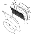
- window assembly 1 has a cutout 3 and window shades 5 and 7 which are positioned so that they can be deployed to block passage of at least some light through cutout 3.
- window shades 5 and 7 are made of any known type of pleated material conventionally used for shades which can be compressed relatively tightly, to a height of less than one-half inch, for example, so that it occupies a minimal amount of space at the top of the window in order to provide an unimpeded view and to allow light to pass completely unobstructed through cutout 3.
- Shade 5 is made of a translucent material that lets some light through.
- Shade 7 is made of an opaque material that lets little or no light through. Each shade can be extended to any desired position.
- shade 5 is first movable to any desired position, such as the partially extended position shown in FIG. 1 .
- Shade 7 remains fully compressed as shade 5 is extended.
- shade 7 can be moved to any desired position. In this way, the passenger has practically an infinite choice of how much light to admit through the window.
- window 1 can be any type of window set in any environment, the present invention is disclosed with particular applicability to an aircraft window.
- an aircraft window is typically contoured to fit the curvature of the particular aircraft body into which it will be installed.
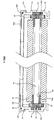
- Window 1 has an inner pane 9 and an outer pane 11.
- a motorized drive mechanism 15 (see FIGS. 4 , 5 and 9 ) is provided for operating window shades 5 and 7.
- Mechanism 15 is placed in shell 17 and is kept in place by a panel 19 which is attached to the shell.
- Inner pane 9 is secured by retainer 21 which is snap-fit into a slot (not shown) in panel 19.
- Outer pane 11 is secured by retainer 23 which is snap-fit onto a flange of shell 17.
- shades 5 and 7 are positioned within the interior space of the window between panes 9 and 11.
- Shades 5 and 7 and some associated drive mechanism components are shown in FIGs. 8 and 10 .
- the shades are shown in their fully compressed form.
- a rail 25 which is comprised of a top cap 27, a bottom cap 29, and a channel 31.
- Caps 27 and 29 are configured so that they can be snap-fit onto channel 31 to secure them in place.
- Cap 27 is slipped through the bottom pleat of shade 5, and then snap-fit onto channel 31. This way the pleat is attached to rail 25.
- Cap 29 is decorative and is used to finish off the appearance of the window shade rail aesthetically.
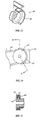
- An axle, or shaft, 33 is configured to be inserted into the through-hole in channel 31. As best shown in FIG. 3 , the ends of axle 33 protrude from channel 31 so that they can carry gears 35 and 37. Gear 35, while positioned inside carrier 36, slides onto the end of axle 33 that has flat 39 on it. As the end of axle 33 passes through opening 34 in boss 34a (see FIGS. 3 , 5 , 7 and 10 ) of carrier 36 to reach gear 35, carrier 36 is simultaneously mounted onto axle 33 along with gear 35. Gear 35 has a corresponding flat 41 so that it is locked to rotate together with the axle. Similarly, gear 37, while positioned inside carrier 38, is lockably mounted onto the other end of axle 33 so as to be rotatable therewith.
- gear 37 is a driven gear
- gear 35 is a passive gear.
- gear 37 As gear 37 is driven, its movement will cooperate with rack 43 in shell 17 (described in detail below with respect to FIGS. 6 and 7 ) to move rail 25 up and down to compress and expand shade 5.
- passive gear 35 Since passive gear 35 is coupled to driven gear 37 by axle 33, the two gears will turn together to produce smooth motion of rail 25 along the window without any twisting of the rail or binding of the gears on the rack that might otherwise occur.
- rail 45 is comprised of a top cap 47, a bottom cap 49, and channel 51.
- Caps 47 and 49 are configured so that they can be snap-fit onto channel 51 to secure them in place.
- Cap 47 is slipped through the bottom pleat of shade 7, and then it is snap-fit onto housing 51. This way the pleat is attached to rail 45.
- Cap 49 is slipped through the top pleat of shade 5, and then it is snap-fit onto channel 51 such that shade 5 is suspended between rails 25 and 45.
- Axle 53 is configured to be inserted into the through-hole in channel 51.
- the ends of axle 53 protrude from channel 51 so that they can carry gears 55 and 57.
- Gear 55 while positioned inside carrier 56, slides onto the end of axle 53 that has flat 59 on it.
- Gear 55 has a corresponding flat 61 so that both are locked to rotate together.
- gear 57 while positioned inside carrier 58, is lockably mounted onto the other end of axle 53 so as to be rotatable therewith.
- gear 55 is a driven gear
- gear 57 is a passive gear.
- gear 55 is driven, its movement will cooperate with rack 43 in shell 17 to move rail 45 up and down to compress and expand shades 5 and 7. Since passive gear 57 is coupled to driven gear 55 by axle 53, the two gears will turn together to produce the same smooth motion of rail 45 achieved for rail 25.
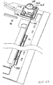
- FIG. 3 clearly shows cable 63 accommodated within channel 75 of carrier 36.
- Cable 63 continues down from carrier 36 to tensioning assembly 67 (see FIG. 5 ) and then loops back up on the other side of retainer 77 to pulley 65.
- Retainer 77 is at the sides of shell 17 (see FIG. 4 ), as described in further detail below.
- the juxtaposition of cable 63 and retainer 77 is best seen in FIG. 3 which shows cable 63 sitting in the recess formed by retainer 77 and cap 160 (see FIG. 4 ).
- FIG. 3 shows cable 63 sitting in the recess formed by retainer 77 and cap 160 (see FIG. 4 ).
- a similar arrangement is shown on the other side of the shade for cable 63a, retainer 77a and cap 160a.
- Axles 33 and 53 are made of pultruded carbon fiber. Caps 27, 29, 47 and 49 are made of plastic, and they can all be identical to each other.
- FIG. 5 a motorized drive mechanism 15 along with shades 5 and 7 are shown.
- Rail 25 is shown along with carriers 36 and 38 mounted to the ends of axle 33 housed within rail 25.
- rail 45 is shown with carriers 56 and 58 mounted to the ends of axle 53 housed within rail 45.
- Passing through carriers 36 and 58 is a loop of a Synchromesh cable 63 that cooperates with motor driven pulley 65 as part of a synchromesh cable drive.
- Synchromesh cable 63 has a straight center section made of a core bundle of braided stainless steel wires encased in a nylon jacket.
- Wound spirally around the nylon jacket is another section made of a core bundle of braided stainless steel wires encased in a polyurethane jacket.
- the spirally wound cable section fits within and engages specially sized and configured helical grooves in the pulley, so that rotation of the pulley produces linear motion of the cable.
- Cable 63 is stretched between the motor driven pulley 65 and cable tensioning assembly 67 (discussed in detail below with respect to FIGS. 11 and 12 ).
- a cable guard 105 (described below in detail in connection with FIGS. 13-15 ) is mounted adjoining cable 63 and pulley 65.
- Motor 69 turns pulley 65. Since cable 63 is meshed with the grooves in pulley 65, rotation of pulley 65 produces corresponding linear motion of cable 63.
- Carrier 56 is a driven carrier because it is fixed to and driven by cable 63.
- carrier 56 has a hole 71 in its end wall 73. (A good view of hole 71 is shown in FIG. 3 with respect to driven carrier 38). This hole 71 goes completely through carrier 38 to a similar opening (not shown) in the opposite end wall. Cable 63 is inserted through one of these openings and exits through the other one to pass completely through carrier 38. Cable 63 is affixed to carrier 56 by a set screw (not shown) inserted into tapped hole 74 (see carrier 38 in FIG. 3 ). Cable 63 then continues to carrier 36 which is a passive carrier because it is not affixed to cable 63. Instead, carrier 36 has an elongated channel 75 passing completely therethrough from one end to the other. Cable 63 runs freely through channel 75. Channel 75 can be curved, as is visible in FIG. 10 , for example, to match the arc followed by cable 63.
- motor 69 is used to extend and compress shade 7.
- motor 69 drives pulley 65.
- rotation of pulley 65 generates linear motion of cable 63.
- carrier 56 is attached to cable 63, they both move together.
- carrier 56 moves, and because its associated gear 55 is in mesh with rack 43, the gear 55 will turn along with axle 53.
- Rotation of axle 53 will cause rotation of gear 57 at the opposite end of the axle.
- gear 57 is in mesh with rack 43, both ends of rail 45 will move synchronously and smoothly to position the shade as desired.
- motor 69 drives only shade 7 and not shade 5.
- cable 63a is stretched between the motor driven pulley 65a and cable tensioning assembly.
- Motor 69a turns pulley 65a. Since cable 63a is meshed with the grooves in pulley 65a, rotation of pulley 65a produces corresponding linear motion of cable 63a.
- Cable 63a is affixed to driven carrier 38. Cable 63a then continues to passive carrier 58 which has the same structure as passive carrier 36. Passive carrier 58 is not affixed to cable 63a. Cable 63a runs freely through carrier 58.
- motor 69a is used to extend and compress shade 5.
- motor 69a is controlled to turn in a particular direction, depending on whether extension or compression of shade 5 is desired, and for a specific number of turns, depending on how much movement of shade 5 is desired, it drives pulley 65a.
- rotation of pulley 65a generates linear motion of cable 63a. Since carrier 38 is attached to cable 63a, they both move together. As carrier 38 moves, and because its associated gear 37 is in mesh with rack 43, the gear 37 will turn along with axle 33. Rotation of axle 33 will cause rotation of gear 35 at the opposite end of the axle. Since gear 35 is in mesh with rack 43, both ends of rail 25 will move synchronously and smoothly to position the shade as desired.
- motor 69a drives only shade 5 and not shade 7.
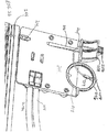
- Motors 69 and 69a receive power from a power source (not shown) in the aircraft transitioning into the window assembly through connector 101 mounted in shell 17. Wires 99 transition from connector body 101 to electronic control circuit 103 in the form of a printed circuit board mounted on shell 17.
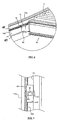
- the motorized drive mechanism 15 is secured within window assembly 1 by retainers 77 and 77a (which are mirror images of each other) at the side edges of shell 17, as shown in FIG. 4 .
- FIGS. 6 and 7 illustrate the retainers in greater detail.
- Retainer 77a has a slot 79 notched into its side. Slot 79 is defined by front wall 81 and rear wall 83.
- Rack 43 is embedded into the front wall 81 to face slot 79.
- Carrier 38 rides within slot 79 and gear 37 meshes with rack 43.
- Cable 63a is also visible in these drawings, as is boss 34a with its opening 34 to receive axle 33.
- FIGS. 11 and 12 show that cable tensioning assembly 67 includes pulleys 85 and 86 rotatably mounted on plate 87 which is pivotably mounted on pillow block 91.
- the pivot point 94 permits rotation of plate 87 relative to pillow block 91.
- a set point adjusting screw 93 is inserted into a threaded opening 92 in plate 87. Screw 93 can slide within slot 95 in block 91 if it is not tightened. Its position within the slot can be fixed by tightening the screw.
- cable 63 is looped around pulleys 65, 85 and 86. As plate 87 is pivoted around pivot point 94, the tension on cable 63 can be adjusted. When the desired tension is reached, screw 93 is tightened to keep plate 89 in that position.
- FIGS. 13-15 show details of cable guard 105. It has a curved surface 107 that is concentric with the pulley 65. Pulley 65 sits within the curvature of surface 107. The slight clearance between them is sized so that, as is apparent from FIGS. 14 and 15 , cable 63 is trapped between pulley 65 and surface 107. This prevents cable 63 from jumping off pulley 65 as the motor 69 applies various forces to the cable.
- There are left and right versions of cable guard 105 which are mirror images of each other.
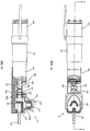
- Window assembly 1 also includes a manual override assembly 111 shown in FIGS. 16 and 17 . This feature is provided so that the window shades can be operated even under conditions when electrical power is lost.
- Motor 69 has a hex-shaped drive shaft 113.
- Drive shaft 113 is mounted in the housing comprised of lower housing 114a and upper housing 114b.
- Drive shaft 113 turns output shaft 115 via manual override assembly 111.
- Output shaft 115 has its pulley driving end drivingly coupled to pulley 65.
- the other end of output shaft 115 is also hex-shaped.
- Coupler 123 is slidably mounted on the hex-shaped ends of shafts 113 and 115 which adjoin each other.
- Spring 125 is under compression between shoulder 127 on the coupler and shoulder 129 on the bottom housing. Thus, spring 125 biases coupler 123 into its coupling position. In this position of coupler 123, rotation of motor drive shaft 113 will be transmitted to pulley 65 via shaft 115.
- the manual override assembly 111 includes a vertical shaft 117 with a bevel gear 119 at its end which is in mesh with bevel gear 121 on output shaft 115.
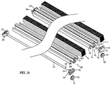
- the top of shaft 117 has an opening 150 (see FIG. 18 ) that is shaped to receive a tool (not shown) that can be inserted and then used to manually turn shaft 117.
- bevel gear 119 As shaft 117 and, along with it, bevel gear 119 are turned, bevel gear 121 can turn shaft 115.
- motor 69 As long as shafts 113 and 115 are coupled to each other, manual rotation of shaft 115 is prevented by motor 69. To avoid this hindrance, a slidable cover 131 is provided.
- flared sides 152 of cover 131 slide on rails 154 and the upper surface 155 of upper housing 114b. As can be appreciated from FIG. 18 , the straight bottom edge 156 of flared side 152 engages under rail 154, while the top 158 rides on surface 155.
- Cover 131 has a bottom skirt 133 that has a half-opening 135 through which shaft 115 passes.
- the wall of skirt 133 that defines opening 135 bears against coupler 123.
- cover 131 is in its static, rest position as spring 125 presses coupler to the right, and coupler 123 likewise presses the skirt to the right.
- Cover 131 has an upwardly extending wall 137 that can serve as a finger catch. Cover 131 can be moved manually to the left by hooking a finger against wall 137 and pushing against the force exerted by spring 125. This uncovers opening 150 in shaft 117 so that the turning tool can be inserted into it. With the tool in the opening, the cover 131 is prevented from returning to its rest position under the influence of spring 125. Thus, cover 131 stays in its displaced position until the turning tool is removed.
- skirt 133 forces coupler 123 to slide off output shaft 115, thereby de-coupling shafts 113 and 115 from each other. This frees output shaft 115 to turn under turning forces applied by shaft 117 and gears 119, 121 without interference from motor 69.
- motors 69 and 69a are each provided with an electromagnetic brake 165 that is activated by the electronic control when the shade reaches its desired position.
- the motors are also provided with gearhead 170.
- Motors 69 and 69a are available from Faulhaber as Part No. 2232V0085.
- the electromagnetic brake 165 is available from Inertia Dynamics LLC as Part No. M1701-0005.
- the gearhead is available from Faulhaber as Part No. 104250.
- Motors 69 and 69a can be replaced by a manual drive arrangement. It could be similar to the manual override assembly 111 as disclosed herein that would function as a permanent drive rather than as an override. However, other manually driven arrangements could also be applied to turn pulley 65 and move cable 63 so as to create linear motion for extending and compressing the shades.
- the manual override assembly 111 discussed above and depicted in FIGs. 16 and 17 requires use of a tool to activate the release mechanism. Such a requirement does not easily provide for passenger activation of the release mechanism to raise the shade material to its open position.
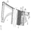
- a shade assembly having an emergency override release (“EOR") mechanism 200 which is readily usable by a passenger is shown.
- the EOR mechanism includes a mounting plate 201 which is affixed to a left frame member 232. It will be appreciated that the mounting plate can, alternatively, be affixed to a right frame member 234 and that either option is a matter of design choice.
- the mounting plate 201 includes features such as guides and seats, as explained below, and is preferably formed of a plastic material through injection molding.
- the mounting plate 201 has a first surface or passenger side 202, i.e., a side facing a passenger who will use the EOR mechanism, and a second, opposite side 204, which is positioned facing an airplane panel.
- a pair of motor release cables 210, 210a - one for each motor 69, 69a, respectively - is provided for disengaging the motor from the pulleys 65 and allowing for manual lifting of the shade material 5, 7. Because both shades are attached to each other in the manner described above, the EOR will raise whichever shade is extended at the time of EOR operation. For simplicity, the EOR is described as operating on shade 5.
- Each motor release cable is telescopically positioned in a release cable sheath 208, 208a. As shown in FIGs.
- each sheath is affixed to a cable seat 206, 206a, and a second end is affixed to a motor release cable seat 240, 240a positioned by each respective motor assembly 69, 69a.
- Each motor release cable 210, 210a is disposed in its respective sheath 208, 208a and is anchored at a first end to a mounting plate 201, and at a second end to a cable anchor 242, 242a at each motor assembly.
- a purpose of the cable sheaths is to provide a cover for, and smooth and sliding movement of, the cables disposed therein. As will be explained below, applying tension to the cables 210, 210a causes decoupling of the motors and allows for manual operation of the shades.
- the second side 204 of mounting plate 201 includes the cable seats 206, 206a.
- An actuator member 260 is positioned in slideable arrangement with the mounting plate by confining the member 260 to an anchor 262 configured as overhang edges affixed to the second side 204.
- An actuator member 260 is configured as a block portion having at one end (the left side with reference to FIG. 24 ), a pair of anchor regions 264, 264a at which an end of each cable 210, 210a is affixed.
- each anchor region is configured as a through-hole for receiving a post or screw (not shown) about which each cable end is secured.
- the opposite side of the actuator member 260 is configured as an actuating arm 266 having a through-hole 268 through which a tether, preferably in the form of a pull cord 244, extends.
- the mounting plate 201 further includes a plurality of posts 209 for receiving fastening screws (not shown) to secure the plate to a shade assembly panel.
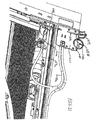
- the mounting plate further includes a guide channel 212 and a feed channel 214 for accommodating an end of the pull cord 244.
- one end of the pull cord is fed through the feed channel 214 and along the guide channel 212 where the pull cord extends along a guide ramp 254 and through the guide door 256.
- the end of the pull cord is formed as a loop 258 which is attached to a pull ring 246 as shown.
- a clamp 259 is provided to secure the pull cord loop 258 to the pull ring 246.
- a ring seat 248 is molded in mounting plate 201 and is dimensioned, relative to the pull ring, to provide a snap-fit therebetween.
- the pull ring 246 is positioned to provide passenger access thereto in order to employ the EOR mechanism.
- the remaining portion of the pull cord extends along and behind an edge of the shade 5 and terminates at a shade clip 250 and, in particular, at a clip extension 252 connected to the shade clip 250.
- the end 247 of the cord may be secured to the clip extension 252 in any manner, such as by feeding the end through a hole in an angled portion of the clip extension and forming a knot, or by an adhesive.
- the clip and clip extension may be formed as a single component part, or as separate parts connected together in any known manner. Moreover, those parts may be formed of plastic, or of a metal, such as aluminum.
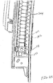
- tensioning assembly 67a as shown in FIG. 26 includes a seal 243 which is compressible by shade clip 250 when the shades are closed.
- the seal is made of an opaque material, preferably rubber, which extends along the edge of the shade cassette housing to prevent light from entering a narrow space that would otherwise exist between the bottom edge of the shade and the bottom edge of the housing when the shade is closed.
- FIGs. 27A and 27B an alternative motor and mounting arrangement to what is depicted in FIGs. 16 and 17 is shown.
- the motor 69a seats between a spring seat 226 and a motor mount 227.
- An output shaft of the motor is connected to a crown gear 228b which mates with a crown gear 228a which, in turn, is connected to the shade assembly for allowing raising and lowering of the shades under motor power during normal operation.
- the motor is biased by compression spring 225 to ensure engagement between crown gears 228a and 228b.
- motor release cable sheath 208a containing cable 210a is connected to cable anchor 242a.
- the motor When the cable 210a is in its rest state, the motor is positioned as shown in FIG. 27A such that the crown gears 228a and 228b are engaged with each other. However, when cable 210a is moved in a direction indicated by arrow "X" in FIG. 27B , the cable anchor causes motor 69a to compress spring 225 and unseat the crown gears from each other. This decouples the motor from the shade assembly and allows the shades to be manually raised in a manner described below.
- the spring clip and extension are disposed at a bottom of the shade track (see Fig. 23 ). It is pointed out that the initial position of the spring clip is independent of any vertical position of the shade 5.
- the actuator member Upon release of the pull cord, the actuator member will return to its original position as shown in FIG. 24 , and the motors will re-engage the crown gears (e.g., crown gear 228a) for normal operation. However, the shade clip will remain in its raised position, a length of the pull cord will be disposed outside of the window shade assembly, and the pull ring 246 will remain unseated from the ring seat 248.
- the EOR mechanism can be re-set to its initial position by simply operating the "down" switch on the shade assembly whereby, as the shade carrier moves downward, the carrier will contact and move the shade clip to its initial position, whereupon the pull cord will be fed back into the channel. Thereafter, the pull ring can be reinserted into the ring seat.
- the EOR mechanism can be used to decouple the motors and allow for manual raising of the shade.
- the EOR can be reset by simply operating the "down" switch as explained above. It is intended, however, that the EOR mechanism will only be used during an operating power failure condition.
Claims (7)
- Manuell betätigter Freigabeüberbrückungsmechanismus (200) für eine motorisierte Rollvorhangbaugruppe (1), die einen Vorhangstoff (5, 7) mit einem vorderen Rand aufweist, wobei der Vorhangstoff (5, 7) hinter einer Scheibe (9, 11) angeordnet ist und zwischen einer geöffneten Position und einer geschlossenen Position auf Betätigung eines Motors (69, 69a) hin bewegbar ist, dadurch gekennzeichnet, dass
der Freigabeüberbrückungsmechanismus (200) aufweist:eine Befestigungsplatte (201);einen Aktuator (260), der gleitbar mit der Befestigungsplatte (201) zum Vorsehen einer Bewegung des Aktuators (260) mit Bezug auf die Befestigungsplatte (201) zwischen einer ersten Position und einer zweiten Position gesichert und in die erste Position vorgespannt ist, wobei der Aktuator (260) eine erste Seite aufweist, die an einem Ende eines Kabels (210, 210a) gesichert ist, und eine zweite Seite aufweist, die ein Durchgangsloch (268) darin ausgebildet aufweist, ein anderes Ende des Kabels (210, 210a) mit dem Motor (69, 69a) verbindbar ist, das Kabel (210, 210a) eine Zugkraft auf den Aktuator (260) zum Vorspannen des Aktuators (260) in die erste Position aufbringt, wodurch der Motor (69, 69a) sich in einer Betriebsposition befindet, wenn der Aktuator (260) in der ersten Position ist, und der Motor in einer entkoppelten Position ist, wenn der Aktuator (260) in der zweiten Position ist; undeinen Gurt (244), der sich durch das Durchgangsloch (268) des Aktuators (260) erstreckt und an einem Ende mit dem Vorhangstoff (5, 7) nahe dem vorderen Rand anbringbar ist, wobei der Gurt (244) gleitbar mit dem Aktuator (260) in Eingriff ist und ein freies Ende (258) aufweist, das einem Bediener zugänglich ist,wobei, wenn das andere Ende des Kabels (210, 210a) mit dem Motor (69, 69a) verbunden ist, das Aufbringen einer Zugkraft auf das freie Ende (258) des Gurts (244) den Aktuator (260) in die zweite Position zwingt und ein Entkoppeln des Motors (69, 69a) von der motorisierten Rollvorhangbaugruppe (1) bewirkt zum Ermöglichen eines manuellen Anhebens des Vorhangstoffes (5, 7) durch Ziehen des Gurts (244) und das Reduzieren der Zugkraft an dem freien Ende (258) des Gurts (244) ein Koppeln des Motors (69, 69a) mit der motorisierten Rollvorhangbaugruppe (1) bewirkt zum Ermöglichen eines motorisierten Betriebs des Vorhangstoffes (5, 7). - Manuell betätigter Freigabeüberbrückungsmechanismus (200) nach Anspruch 1, wobei die Befestigungsplatte (201) einen Anker (262) zum Aufrechterhalten eines gleitbaren Eingriffs des Aktuators (260) in die Befestigungsplatte (201) aufweist.
- Manuell betätigter Freigabeüberbrückungsmechanismus (200) nach Anspruch 1 oder 2, ferner enthaltend eine Feder (225), wobei die Feder (225) derart ausgebildet ist, dass sie den Motor (69, 69a) in eine Eingriffsposition vorspannt, und derart ausgebildet ist, dass sie den Motor (69, 69a) durch eine Kompression der Feder (225) während des Ziehens des freien Endes (258) des Gurts (244) entkoppelt.
- Manuell betätigter Freigabeüberbrückungsmechanismus (200) nach einem der Ansprüche 1 bis 3, ferner enthaltend einen Zugring (246), der mit dem freien Ende des Gurts (244) verbunden ist, und wobei die Befestigungsplatte (201) einen Ringsitz (248) aufweist, in dem der Zugring (246) während eines Nichtgebrauchs des Freigabeüberbrückungsmechanismus (200) verstaut ist.
- Manuell betätigter Freigabeüberbrückungsmechanismus (200) nach einem der vorhergehenden Ansprüche, wobei der Gurt (244) eine Zugschnur aufweist.
- Manuell betätigter Freigabeüberbrückungsmechanismus (200) nach Anspruch 5, wobei eine Länge der Zugschnur sich von der Rollvorhangbaugruppe (1) auf ein erneutes Koppeln des Motors (69, 69a) mit der Rollvorhangbaugruppe (1) hin erstreckt, und wobei die Länge der Zugschnur in die Rollvorhangbaugruppe (1) durch Betätigung des Motors (69, 69a) zurückgezogen wird.
- Manuell betätigter Freigabeüberbrückungsmechanismus (200) nach einem der vorhergehenden Ansprüche, wobei der Vorhangstoff ein Paar von Vorhangstoffen aufweist, wobei jeder Stoff von einem entsprechenden einen aus einem Paar von Motoren gesteuert wird, wobei das Aufbringen einer Zugkraft auf den Gurt das Paar von Motoren entkoppelt und beide Vorhangstoffe anhebt, und wobei das Reduzieren der Zugkraft ein erneutes Koppeln des Paars von Motoren bewirkt.
Applications Claiming Priority (2)
| Application Number | Priority Date | Filing Date | Title |
|---|---|---|---|
| US201261714098P | 2012-10-15 | 2012-10-15 | |
| PCT/US2013/065018 WO2014062662A1 (en) | 2012-10-15 | 2013-10-15 | Emergency override release mechanism for motorized window shade assembly |
Publications (3)
| Publication Number | Publication Date |
|---|---|
| EP2917444A1 EP2917444A1 (de) | 2015-09-16 |
| EP2917444A4 EP2917444A4 (de) | 2016-08-03 |
| EP2917444B1 true EP2917444B1 (de) | 2018-01-17 |
Family
ID=50488691
Family Applications (1)
| Application Number | Title | Priority Date | Filing Date |
|---|---|---|---|
| EP13846418.5A Not-in-force EP2917444B1 (de) | 2012-10-15 | 2013-10-15 | Freigabemechanismus für motorisierte jalousieanordnung im notfall |
Country Status (6)
| Country | Link |
|---|---|
| US (1) | US9677329B2 (de) |
| EP (1) | EP2917444B1 (de) |
| CN (1) | CN105556048B (de) |
| BR (1) | BR112015008486A2 (de) |
| CA (1) | CA2888482A1 (de) |
| WO (1) | WO2014062662A1 (de) |
Families Citing this family (6)
| Publication number | Priority date | Publication date | Assignee | Title |
|---|---|---|---|---|
| USD734060S1 (en) * | 2013-04-01 | 2015-07-14 | Hunter Douglas Inc. | Cellular shade component |
| CA2870983A1 (en) * | 2014-11-06 | 2016-05-06 | Etapa Window Fashions Inc | Motor retrofitted on roll-up blind cords |
| US10731411B2 (en) * | 2016-10-19 | 2020-08-04 | Hunter Douglas, Inc. | End caps for architectural coverings |
| US10459476B2 (en) * | 2016-12-22 | 2019-10-29 | Aktiebolaget Skf | Actuator manual override device |
| US11059560B2 (en) * | 2018-09-19 | 2021-07-13 | The Boeing Company | Window assembly for use in a vehicle |
| JP7185222B2 (ja) * | 2018-10-22 | 2022-12-07 | 株式会社総合車両製作所 | 遮光装置 |
Family Cites Families (8)
| Publication number | Priority date | Publication date | Assignee | Title |
|---|---|---|---|---|
| US3561520A (en) | 1969-07-14 | 1971-02-09 | Robert A Gill | Drapery actuator |
| US6230784B1 (en) * | 1997-09-25 | 2001-05-15 | Msa Aircraft Products Ltd. | Electrically operated aircraft window with a sliding take-up spool |
| US6186211B1 (en) * | 1999-02-22 | 2001-02-13 | Aerospace Technologies Group, Inc. | Window assembly with a motorized window shade mechanism |
| DE20203221U1 (de) * | 2001-03-05 | 2002-05-16 | Hoermann Kg Antriebstechnik | Störfalltrennvorrichtung zum Trennen eines Torantriebes von einem Tor sowie damit versehenes Tor |
| US7690414B2 (en) * | 2006-12-26 | 2010-04-06 | Aerospace Technologies Group, Inc. | Motorized window shade |
| US8220521B2 (en) * | 2008-11-22 | 2012-07-17 | Diehl Aircabin Gmbh | Device for darkening a cabin window |
| US9045215B2 (en) * | 2009-11-11 | 2015-06-02 | Aerospace Technologies Group, Inc. | Window assembly with a motorized window shade mechanism |
| EP2665395A4 (de) * | 2011-01-13 | 2015-10-14 | Aerospace Technologies Group Inc | Verbesserter motorisierter fensterladenmechanismus |
-
2013
- 2013-10-15 CN CN201380059120.2A patent/CN105556048B/zh not_active Expired - Fee Related
- 2013-10-15 US US14/436,011 patent/US9677329B2/en not_active Expired - Fee Related
- 2013-10-15 EP EP13846418.5A patent/EP2917444B1/de not_active Not-in-force
- 2013-10-15 WO PCT/US2013/065018 patent/WO2014062662A1/en active Application Filing
- 2013-10-15 BR BR112015008486A patent/BR112015008486A2/pt not_active IP Right Cessation
- 2013-10-15 CA CA2888482A patent/CA2888482A1/en not_active Abandoned
Non-Patent Citations (1)
| Title |
|---|
| None * |
Also Published As
| Publication number | Publication date |
|---|---|
| EP2917444A4 (de) | 2016-08-03 |
| EP2917444A1 (de) | 2015-09-16 |
| CN105556048B (zh) | 2018-02-02 |
| CA2888482A1 (en) | 2014-04-24 |
| BR112015008486A2 (pt) | 2017-07-04 |
| CN105556048A (zh) | 2016-05-04 |
| US9677329B2 (en) | 2017-06-13 |
| WO2014062662A1 (en) | 2014-04-24 |
| US20150267465A1 (en) | 2015-09-24 |
Similar Documents
| Publication | Publication Date | Title |
|---|---|---|
| EP2917444B1 (de) | Freigabemechanismus für motorisierte jalousieanordnung im notfall | |
| US9045215B2 (en) | Window assembly with a motorized window shade mechanism | |
| US7537039B2 (en) | Window blind driven by a window lifter | |
| US6481486B1 (en) | Modular aircraft window with a dual shade | |
| US5784833A (en) | Silding window with motor-driven regulator | |
| US7992928B2 (en) | Vehicle roof structure | |
| JP4247751B2 (ja) | サンシェード装置 | |
| US6230784B1 (en) | Electrically operated aircraft window with a sliding take-up spool | |
| US20080034667A1 (en) | Manual window blind with automatic retraction | |
| US20070023152A1 (en) | Roller blind with smooth pusher elements | |
| US20140048219A1 (en) | Motorized window shade mechanism | |
| US10669764B2 (en) | Rail module with cable conduits for window regulator systems | |
| US11866981B2 (en) | Actuation system | |
| US8690225B2 (en) | Actuation mechanism for a sliding door of a motor vehicle | |
| US20180178634A1 (en) | Shading device for a motor vehicle window | |
| CN110525354B (zh) | 一种汽车内饰件 | |
| US20060000565A1 (en) | Device for opening and closing a curtain, notably in order to automate the phases of opening and closing of the curtain | |
| US20030005640A1 (en) | Motor vehicle door drive mechanism, with corresponding door, carriage and vehicle | |
| JP5167650B2 (ja) | 車両用サンシェード装置 | |
| WO2013040054A1 (en) | Window shade assembly with manual actuator mechanism | |
| CA3197576A1 (en) | Panel device | |
| WO2021137790A1 (en) | An openable and closable frame mechanism in the horizontal axis |
Legal Events
| Date | Code | Title | Description |
|---|---|---|---|
| PUAI | Public reference made under article 153(3) epc to a published international application that has entered the european phase |
Free format text: ORIGINAL CODE: 0009012 |
|
| 17P | Request for examination filed |
Effective date: 20150415 |
|
| AK | Designated contracting states |
Kind code of ref document: A1 Designated state(s): AL AT BE BG CH CY CZ DE DK EE ES FI FR GB GR HR HU IE IS IT LI LT LU LV MC MK MT NL NO PL PT RO RS SE SI SK SM TR |
|
| AX | Request for extension of the european patent |
Extension state: BA ME |
|
| DAX | Request for extension of the european patent (deleted) | ||
| RA4 | Supplementary search report drawn up and despatched (corrected) |
Effective date: 20160701 |
|
| RIC1 | Information provided on ipc code assigned before grant |
Ipc: E06B 9/74 20060101AFI20160627BHEP Ipc: B64C 1/14 20060101ALI20160627BHEP Ipc: E06B 9/262 20060101ALN20160627BHEP |
|
| 17Q | First examination report despatched |
Effective date: 20170504 |
|
| REG | Reference to a national code |
Ref country code: DE Ref legal event code: R079 Ref document number: 602013032422 Country of ref document: DE Free format text: PREVIOUS MAIN CLASS: E06B0009680000 Ipc: E06B0009740000 |
|
| GRAP | Despatch of communication of intention to grant a patent |
Free format text: ORIGINAL CODE: EPIDOSNIGR1 |
|
| RIC1 | Information provided on ipc code assigned before grant |
Ipc: B64C 1/14 20060101ALI20170727BHEP Ipc: E06B 9/262 20060101ALN20170727BHEP Ipc: E06B 9/322 20060101ALI20170727BHEP Ipc: E06B 9/24 20060101ALI20170727BHEP Ipc: E06B 9/74 20060101AFI20170727BHEP |
|
| INTG | Intention to grant announced |
Effective date: 20170822 |
|
| GRAS | Grant fee paid |
Free format text: ORIGINAL CODE: EPIDOSNIGR3 |
|
| GRAA | (expected) grant |
Free format text: ORIGINAL CODE: 0009210 |
|
| AK | Designated contracting states |
Kind code of ref document: B1 Designated state(s): AL AT BE BG CH CY CZ DE DK EE ES FI FR GB GR HR HU IE IS IT LI LT LU LV MC MK MT NL NO PL PT RO RS SE SI SK SM TR |
|
| REG | Reference to a national code |
Ref country code: GB Ref legal event code: FG4D |
|
| REG | Reference to a national code |
Ref country code: CH Ref legal event code: EP |
|
| REG | Reference to a national code |
Ref country code: IE Ref legal event code: FG4D |
|
| REG | Reference to a national code |
Ref country code: AT Ref legal event code: REF Ref document number: 964550 Country of ref document: AT Kind code of ref document: T Effective date: 20180215 |
|
| REG | Reference to a national code |
Ref country code: DE Ref legal event code: R096 Ref document number: 602013032422 Country of ref document: DE |
|
| REG | Reference to a national code |
Ref country code: SE Ref legal event code: TRGR |
|
| REG | Reference to a national code |
Ref country code: NL Ref legal event code: MP Effective date: 20180117 |
|
| REG | Reference to a national code |
Ref country code: LT Ref legal event code: MG4D |
|
| REG | Reference to a national code |
Ref country code: AT Ref legal event code: MK05 Ref document number: 964550 Country of ref document: AT Kind code of ref document: T Effective date: 20180117 |
|
| PG25 | Lapsed in a contracting state [announced via postgrant information from national office to epo] |
Ref country code: NL Free format text: LAPSE BECAUSE OF FAILURE TO SUBMIT A TRANSLATION OF THE DESCRIPTION OR TO PAY THE FEE WITHIN THE PRESCRIBED TIME-LIMIT Effective date: 20180117 |
|
| PG25 | Lapsed in a contracting state [announced via postgrant information from national office to epo] |
Ref country code: NO Free format text: LAPSE BECAUSE OF FAILURE TO SUBMIT A TRANSLATION OF THE DESCRIPTION OR TO PAY THE FEE WITHIN THE PRESCRIBED TIME-LIMIT Effective date: 20180417 Ref country code: CY Free format text: LAPSE BECAUSE OF FAILURE TO SUBMIT A TRANSLATION OF THE DESCRIPTION OR TO PAY THE FEE WITHIN THE PRESCRIBED TIME-LIMIT Effective date: 20180117 Ref country code: LT Free format text: LAPSE BECAUSE OF FAILURE TO SUBMIT A TRANSLATION OF THE DESCRIPTION OR TO PAY THE FEE WITHIN THE PRESCRIBED TIME-LIMIT Effective date: 20180117 Ref country code: ES Free format text: LAPSE BECAUSE OF FAILURE TO SUBMIT A TRANSLATION OF THE DESCRIPTION OR TO PAY THE FEE WITHIN THE PRESCRIBED TIME-LIMIT Effective date: 20180117 Ref country code: HR Free format text: LAPSE BECAUSE OF FAILURE TO SUBMIT A TRANSLATION OF THE DESCRIPTION OR TO PAY THE FEE WITHIN THE PRESCRIBED TIME-LIMIT Effective date: 20180117 Ref country code: FI Free format text: LAPSE BECAUSE OF FAILURE TO SUBMIT A TRANSLATION OF THE DESCRIPTION OR TO PAY THE FEE WITHIN THE PRESCRIBED TIME-LIMIT Effective date: 20180117 |
|
| PG25 | Lapsed in a contracting state [announced via postgrant information from national office to epo] |
Ref country code: GR Free format text: LAPSE BECAUSE OF FAILURE TO SUBMIT A TRANSLATION OF THE DESCRIPTION OR TO PAY THE FEE WITHIN THE PRESCRIBED TIME-LIMIT Effective date: 20180418 Ref country code: BG Free format text: LAPSE BECAUSE OF FAILURE TO SUBMIT A TRANSLATION OF THE DESCRIPTION OR TO PAY THE FEE WITHIN THE PRESCRIBED TIME-LIMIT Effective date: 20180417 Ref country code: PL Free format text: LAPSE BECAUSE OF FAILURE TO SUBMIT A TRANSLATION OF THE DESCRIPTION OR TO PAY THE FEE WITHIN THE PRESCRIBED TIME-LIMIT Effective date: 20180117 Ref country code: AT Free format text: LAPSE BECAUSE OF FAILURE TO SUBMIT A TRANSLATION OF THE DESCRIPTION OR TO PAY THE FEE WITHIN THE PRESCRIBED TIME-LIMIT Effective date: 20180117 Ref country code: RS Free format text: LAPSE BECAUSE OF FAILURE TO SUBMIT A TRANSLATION OF THE DESCRIPTION OR TO PAY THE FEE WITHIN THE PRESCRIBED TIME-LIMIT Effective date: 20180117 Ref country code: IS Free format text: LAPSE BECAUSE OF FAILURE TO SUBMIT A TRANSLATION OF THE DESCRIPTION OR TO PAY THE FEE WITHIN THE PRESCRIBED TIME-LIMIT Effective date: 20180517 Ref country code: LV Free format text: LAPSE BECAUSE OF FAILURE TO SUBMIT A TRANSLATION OF THE DESCRIPTION OR TO PAY THE FEE WITHIN THE PRESCRIBED TIME-LIMIT Effective date: 20180117 |
|
| REG | Reference to a national code |
Ref country code: DE Ref legal event code: R097 Ref document number: 602013032422 Country of ref document: DE |
|
| PG25 | Lapsed in a contracting state [announced via postgrant information from national office to epo] |
Ref country code: AL Free format text: LAPSE BECAUSE OF FAILURE TO SUBMIT A TRANSLATION OF THE DESCRIPTION OR TO PAY THE FEE WITHIN THE PRESCRIBED TIME-LIMIT Effective date: 20180117 Ref country code: RO Free format text: LAPSE BECAUSE OF FAILURE TO SUBMIT A TRANSLATION OF THE DESCRIPTION OR TO PAY THE FEE WITHIN THE PRESCRIBED TIME-LIMIT Effective date: 20180117 Ref country code: EE Free format text: LAPSE BECAUSE OF FAILURE TO SUBMIT A TRANSLATION OF THE DESCRIPTION OR TO PAY THE FEE WITHIN THE PRESCRIBED TIME-LIMIT Effective date: 20180117 |
|
| PLBE | No opposition filed within time limit |
Free format text: ORIGINAL CODE: 0009261 |
|
| STAA | Information on the status of an ep patent application or granted ep patent |
Free format text: STATUS: NO OPPOSITION FILED WITHIN TIME LIMIT |
|
| PG25 | Lapsed in a contracting state [announced via postgrant information from national office to epo] |
Ref country code: CZ Free format text: LAPSE BECAUSE OF FAILURE TO SUBMIT A TRANSLATION OF THE DESCRIPTION OR TO PAY THE FEE WITHIN THE PRESCRIBED TIME-LIMIT Effective date: 20180117 Ref country code: SM Free format text: LAPSE BECAUSE OF FAILURE TO SUBMIT A TRANSLATION OF THE DESCRIPTION OR TO PAY THE FEE WITHIN THE PRESCRIBED TIME-LIMIT Effective date: 20180117 Ref country code: DK Free format text: LAPSE BECAUSE OF FAILURE TO SUBMIT A TRANSLATION OF THE DESCRIPTION OR TO PAY THE FEE WITHIN THE PRESCRIBED TIME-LIMIT Effective date: 20180117 Ref country code: SK Free format text: LAPSE BECAUSE OF FAILURE TO SUBMIT A TRANSLATION OF THE DESCRIPTION OR TO PAY THE FEE WITHIN THE PRESCRIBED TIME-LIMIT Effective date: 20180117 |
|
| 26N | No opposition filed |
Effective date: 20181018 |
|
| PG25 | Lapsed in a contracting state [announced via postgrant information from national office to epo] |
Ref country code: SI Free format text: LAPSE BECAUSE OF FAILURE TO SUBMIT A TRANSLATION OF THE DESCRIPTION OR TO PAY THE FEE WITHIN THE PRESCRIBED TIME-LIMIT Effective date: 20180117 |
|
| REG | Reference to a national code |
Ref country code: DE Ref legal event code: R119 Ref document number: 602013032422 Country of ref document: DE |
|
| REG | Reference to a national code |
Ref country code: SE Ref legal event code: EUG |
|
| REG | Reference to a national code |
Ref country code: CH Ref legal event code: PL |
|
| GBPC | Gb: european patent ceased through non-payment of renewal fee |
Effective date: 20181015 |
|
| REG | Reference to a national code |
Ref country code: BE Ref legal event code: MM Effective date: 20181031 |
|
| PG25 | Lapsed in a contracting state [announced via postgrant information from national office to epo] |
Ref country code: MC Free format text: LAPSE BECAUSE OF FAILURE TO SUBMIT A TRANSLATION OF THE DESCRIPTION OR TO PAY THE FEE WITHIN THE PRESCRIBED TIME-LIMIT Effective date: 20180117 Ref country code: LU Free format text: LAPSE BECAUSE OF NON-PAYMENT OF DUE FEES Effective date: 20181015 |
|
| REG | Reference to a national code |
Ref country code: IE Ref legal event code: MM4A |
|
| PG25 | Lapsed in a contracting state [announced via postgrant information from national office to epo] |
Ref country code: DE Free format text: LAPSE BECAUSE OF NON-PAYMENT OF DUE FEES Effective date: 20190501 Ref country code: SE Free format text: LAPSE BECAUSE OF NON-PAYMENT OF DUE FEES Effective date: 20181016 |
|
| PG25 | Lapsed in a contracting state [announced via postgrant information from national office to epo] |
Ref country code: FR Free format text: LAPSE BECAUSE OF NON-PAYMENT OF DUE FEES Effective date: 20181031 Ref country code: CH Free format text: LAPSE BECAUSE OF NON-PAYMENT OF DUE FEES Effective date: 20181031 Ref country code: LI Free format text: LAPSE BECAUSE OF NON-PAYMENT OF DUE FEES Effective date: 20181031 Ref country code: BE Free format text: LAPSE BECAUSE OF NON-PAYMENT OF DUE FEES Effective date: 20181031 |
|
| PG25 | Lapsed in a contracting state [announced via postgrant information from national office to epo] |
Ref country code: IE Free format text: LAPSE BECAUSE OF NON-PAYMENT OF DUE FEES Effective date: 20181015 Ref country code: GB Free format text: LAPSE BECAUSE OF NON-PAYMENT OF DUE FEES Effective date: 20181015 Ref country code: IT Free format text: LAPSE BECAUSE OF NON-PAYMENT OF DUE FEES Effective date: 20181015 |
|
| PG25 | Lapsed in a contracting state [announced via postgrant information from national office to epo] |
Ref country code: MT Free format text: LAPSE BECAUSE OF NON-PAYMENT OF DUE FEES Effective date: 20181015 |
|
| PG25 | Lapsed in a contracting state [announced via postgrant information from national office to epo] |
Ref country code: TR Free format text: LAPSE BECAUSE OF FAILURE TO SUBMIT A TRANSLATION OF THE DESCRIPTION OR TO PAY THE FEE WITHIN THE PRESCRIBED TIME-LIMIT Effective date: 20180117 |
|
| PG25 | Lapsed in a contracting state [announced via postgrant information from national office to epo] |
Ref country code: PT Free format text: LAPSE BECAUSE OF FAILURE TO SUBMIT A TRANSLATION OF THE DESCRIPTION OR TO PAY THE FEE WITHIN THE PRESCRIBED TIME-LIMIT Effective date: 20180117 |
|
| PG25 | Lapsed in a contracting state [announced via postgrant information from national office to epo] |
Ref country code: HU Free format text: LAPSE BECAUSE OF FAILURE TO SUBMIT A TRANSLATION OF THE DESCRIPTION OR TO PAY THE FEE WITHIN THE PRESCRIBED TIME-LIMIT; INVALID AB INITIO Effective date: 20131015 Ref country code: MK Free format text: LAPSE BECAUSE OF NON-PAYMENT OF DUE FEES Effective date: 20180117 |