EP2916035A1 - Timing belt for suction feeder - Google Patents
Timing belt for suction feeder Download PDFInfo
- Publication number
- EP2916035A1 EP2916035A1 EP13851269.4A EP13851269A EP2916035A1 EP 2916035 A1 EP2916035 A1 EP 2916035A1 EP 13851269 A EP13851269 A EP 13851269A EP 2916035 A1 EP2916035 A1 EP 2916035A1
- Authority
- EP
- European Patent Office
- Prior art keywords
- fabric
- timing belt
- belt
- tooth
- rubber
- Prior art date
- Legal status (The legal status is an assumption and is not a legal conclusion. Google has not performed a legal analysis and makes no representation as to the accuracy of the status listed.)
- Granted
Links
Images




Classifications
-
- B—PERFORMING OPERATIONS; TRANSPORTING
- B65—CONVEYING; PACKING; STORING; HANDLING THIN OR FILAMENTARY MATERIAL
- B65G—TRANSPORT OR STORAGE DEVICES, e.g. CONVEYORS FOR LOADING OR TIPPING, SHOP CONVEYOR SYSTEMS OR PNEUMATIC TUBE CONVEYORS
- B65G15/00—Conveyors having endless load-conveying surfaces, i.e. belts and like continuous members, to which tractive effort is transmitted by means other than endless driving elements of similar configuration
- B65G15/30—Belts or like endless load-carriers
- B65G15/32—Belts or like endless load-carriers made of rubber or plastics
- B65G15/42—Belts or like endless load-carriers made of rubber or plastics having ribs, ridges, or other surface projections
-
- B—PERFORMING OPERATIONS; TRANSPORTING
- B65—CONVEYING; PACKING; STORING; HANDLING THIN OR FILAMENTARY MATERIAL
- B65G—TRANSPORT OR STORAGE DEVICES, e.g. CONVEYORS FOR LOADING OR TIPPING, SHOP CONVEYOR SYSTEMS OR PNEUMATIC TUBE CONVEYORS
- B65G15/00—Conveyors having endless load-conveying surfaces, i.e. belts and like continuous members, to which tractive effort is transmitted by means other than endless driving elements of similar configuration
- B65G15/30—Belts or like endless load-carriers
- B65G15/58—Belts or like endless load-carriers with means for holding or retaining the loads in fixed position, e.g. magnetic
-
- F—MECHANICAL ENGINEERING; LIGHTING; HEATING; WEAPONS; BLASTING
- F16—ENGINEERING ELEMENTS AND UNITS; GENERAL MEASURES FOR PRODUCING AND MAINTAINING EFFECTIVE FUNCTIONING OF MACHINES OR INSTALLATIONS; THERMAL INSULATION IN GENERAL
- F16G—BELTS, CABLES, OR ROPES, PREDOMINANTLY USED FOR DRIVING PURPOSES; CHAINS; FITTINGS PREDOMINANTLY USED THEREFOR
- F16G1/00—Driving-belts
- F16G1/06—Driving-belts made of rubber
- F16G1/08—Driving-belts made of rubber with reinforcement bonded by the rubber
- F16G1/10—Driving-belts made of rubber with reinforcement bonded by the rubber with textile reinforcement
-
- F—MECHANICAL ENGINEERING; LIGHTING; HEATING; WEAPONS; BLASTING
- F16—ENGINEERING ELEMENTS AND UNITS; GENERAL MEASURES FOR PRODUCING AND MAINTAINING EFFECTIVE FUNCTIONING OF MACHINES OR INSTALLATIONS; THERMAL INSULATION IN GENERAL
- F16G—BELTS, CABLES, OR ROPES, PREDOMINANTLY USED FOR DRIVING PURPOSES; CHAINS; FITTINGS PREDOMINANTLY USED THEREFOR
- F16G1/00—Driving-belts
- F16G1/28—Driving-belts with a contact surface of special shape, e.g. toothed
-
- B—PERFORMING OPERATIONS; TRANSPORTING
- B65—CONVEYING; PACKING; STORING; HANDLING THIN OR FILAMENTARY MATERIAL
- B65G—TRANSPORT OR STORAGE DEVICES, e.g. CONVEYORS FOR LOADING OR TIPPING, SHOP CONVEYOR SYSTEMS OR PNEUMATIC TUBE CONVEYORS
- B65G15/00—Conveyors having endless load-conveying surfaces, i.e. belts and like continuous members, to which tractive effort is transmitted by means other than endless driving elements of similar configuration
- B65G15/30—Belts or like endless load-carriers
- B65G15/32—Belts or like endless load-carriers made of rubber or plastics
- B65G15/34—Belts or like endless load-carriers made of rubber or plastics with reinforcing layers, e.g. of fabric
-
- B—PERFORMING OPERATIONS; TRANSPORTING
- B65—CONVEYING; PACKING; STORING; HANDLING THIN OR FILAMENTARY MATERIAL
- B65G—TRANSPORT OR STORAGE DEVICES, e.g. CONVEYORS FOR LOADING OR TIPPING, SHOP CONVEYOR SYSTEMS OR PNEUMATIC TUBE CONVEYORS
- B65G21/00—Supporting or protective framework or housings for endless load-carriers or traction elements of belt or chain conveyors
- B65G21/20—Means incorporated in, or attached to, framework or housings for guiding load-carriers, traction elements or loads supported on moving surfaces
- B65G21/2027—Suction retaining means
Definitions
- the present invention relates to a packaging machine for supplying contents to a pillow-shaped film pouch, and more particularly, relates to a timing belt for a suction feeder, used for conveying film which is shaped in a cylindrical form.
- such a packaging machine is constructed in such a manner that a cylindrical film pouch can be conveyed while maintaining its cylindrically inflated state so that contents such as cakes can be filled therein.
- a pair of timing belts is disposed along the conveying direction of the cylindrical film pouch, and these timing belts are formed with suction holes so that a negative pressure is applied in order to suck and inflate the cylindrical film pouch.
- a timing belt provided with suction holes one disclosed in Patent Document 1 is known, in which the suction holes are formed in a flat area of the central portion of the timing belt, in which belt teeth are not formed, for example.
- PATENT DOCUMENT 1 Unexamined Utility Model Publication No. (HEI) 7-38021
- a method for forming the flat area at the central portion of the timing belt in order to form the suction holes, usually, a method is adopted, in which belt teeth of the central portion are shaved off. However, due to such a machining, a layer such as rubber, urethane, or cords is exposed in the flat area.
- a surface on which belt teeth are formed is not only engaged with a drive pulley, but also slidingly contacted with a suction chamber for sucking the cylindrical film pouch toward the belt.
- the object of the invention is to provide a timing belt for a suction feeder, in which wear debris is not generated and sliding resistance is suppressed as much as possible to prevent the generation of heat, so that the load of the power source can be reduced.
- the suction feeder timing belt has a feature which comprises a planar conveying surface; a driving surface positioned opposite to the conveying surface, with the driving surface having a flat surface extending in the longitudinal direction of the timing belt at the center portion in the lateral direction of the timing belt, and the driving surface having belt teeth formed at a constant interval in the longitudinal direction on both of the outer sides of the center portion; and a fabric covering the whole of the driving surface, with the fabric being stretchable in both the longitudinal and lateral directions of the timing belt.
- a cord is embedded in tooth rubber forming the driving surface, and an intermediate rubber layer is provided between the fabric and the cord. Due to the intermediate rubber layer, flatness of the flat surface is ensured in spite of the provision of the cords.
- the fabric is a woven fabric, for example.
- the stretch ratio of the fabric is greater than or equal to 35% in the longitudinal direction, for example, and the stretch ratio of the fabric is greater than or equal to 10% in the lateral direction, for example.
- the stretch ratio of the fabric is greater than or equal to 80% in the longitudinal direction, and the stretch ratio of the fabric is greater than or equal to 50% in the lateral direction.
- the fabric covers the flat surface, a tooth bottom portion formed between two adjacent belt teeth, a tip portion of the belt tooth, a tooth side portion formed between the tip portion and the tooth bottom portion, and a tooth end portion positioned on the flat-surface side of the belt tooth.
- the flat surface is configured with suction holes, which are drilled at a predetermined interval in the longitudinal direction and penetrate through the conveying surface. This is for applying a negative pressure onto an outer surface of the cylindrical film pouch conveyed by the timing belt.
- the suction feeder timing belt of the present invention wear debris is not generated and sliding resistance is suppressed as much as possible to prevent the generation of heat when being used in a packaging machine which feeds a packaging film pouch. Further, not only can the load of the power source be reduced, but also a stable negative pressure is always generated. Furthermore, since the fabric has elasticity both in the longitudinal direction and the lateral direction of the timing belt, adhesiveness of the fabric with respect to the tooth rubber is improved, by which the fabric is prevented from separating in an early stage, and is prevented from being imperfectly molded.
- Fig. 1 shows a general construction of a packaging machine, which uses the timing belt.
- This packaging machine is configured such that, while forming sheet-shaped film F into a cylinder, contents A such as cakes are supplied to the film pouch F.
- contents A such as cakes are supplied to the film pouch F.
- the lower end B of the cylindrically formed film pouch F is sealed, and under this condition, the contents A are supplied into the cylindrically formed film pouch F.
- the upper portion C of the cylindrically formed film pouch F, in which the contents A are filled, is sealed and cut at the lower portion of the packaging machine, and the pillow-shaped film pouch D is conveyed to the next process.
- Endless timing belts 13 and 14 are provided on the both sides of the guide member 11.
- the timing belts 13 and 14 face the guide member 11 with enough space in between to pass the film F.
- the timing belt 13 is wound around pulleys 15 and 16, and the timing belt 14 is wound around pulleys 17 and 18.
- the pulleys 16 and 18 rotate in the directions of the arrows P and Q. Namely, the timing belt 13 and 14 rotate such that the sides of the guide member 11 move downward in the drawing.
- a suction chamber 21 is provided between the pulleys 15 and 16, and is in contact with a flat surface of the inner surface (driving surface) of the timing belt 13.
- a suction chamber 22 is provided between the pulleys 17 and 18, and is in contact with the inner surface of the timing belt 14.
- the suction chambers 13 and 14 are connected to a negative pressure source (not shown).
- the timing belts 13 and 14 are formed with suction holes (not shown), so that a negative pressure occurring in the suction chambers 21 and 22 is applied to the film F through the suction holes.
- the film F is sheet-shaped above the hopper 12, and is deformed into a cylinder covering the outer surface of the guide member 11 by a forming machine (not shown). Edge portions of the film F, along the axis of the guide member 11, are adhered to each other, and the lower end B is sealed. In this process, the cylindrical shape of the film F is kept due to the negative pressure supplied by the suction chambers 21 and 22.
- the cylindrical film F is conveyed downward by the timing belts 13 and 14, and at the same time, the contents A supplied through the hopper 12 are accumulated in the lower part of the film F.
- the upper end C is sealed and cut at the position of the broken line E.
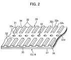
- Fig. 2 shows an inner surface or a driving surface 30 of the timing belts 13 and 14.
- a flat surface 31 is formed extending in the longitudinal direction of the timing belts 13 and 14 at the center portion in the lateral direction of the timing belts 13 and 14.
- Belt teeth 32 are formed at a constant interval in the longitudinal direction of the timing belt on both of the outer sides of the center portion.
- the flat surface 31 is configured with suction holes 33.
- the suction holes 33 are drilled at a predetermined interval in the longitudinal direction and penetrate through the conveying surface 37, which is opposite to the driving surface 30.
- a tip portion 32a of the belt teeth 32 is an approximately flat surface, and a tooth bottom portion 34 formed between the two adjacent belt teeth 32 is a flat surface slightly greater than the tip portion 32a.
- Tooth side portions 32b and 32c positioned between the tip portion 32a and the tooth bottom portion 34 are inclined.
- a tooth end portion 32d positioned at the flat surface 31 side of the belt tooth 32 is vertical to the flat surface 31 (see Fig. 6 ).
- the whole of the driving surface 30 is covered with a fabric 36.
- the fabric 36 covers the flat surface 31, the tooth bottom portion 34, the tip portion 32a of the belt teeth 32, the tooth side portions 32b and 32c, and the tooth end portion 32d.
- outer side surfaces 35 of the timing belts 13 and 14 and cylindrical inner wall 33a of the suction holes 33 are not covered with the fabric 36, leaving the rubber exposed in those areas.
- Fig. 3 is a plan view of the timing belts 13 and 14 as seen from the conveying surface 37 side.
- Fig. 4 is a side view of the timing belts 13 and 14.
- Fig. 5 is a bottom view of the timing belts 13 and 14 viewed from the driving surface side.
- the conveying surface 37 is flat, an elliptical recess 38 is formed around the suction hole 33, so that the surrounding portion is slightly indented in the conveying surface 37.
- the suction hole 33 is circular, and is positioned at the center of the recess 38.
- the tooth rubber 41 forming the driving surface 30 of the timing belts 13 and 14 is NBR rubber, in which the hardness is 74JIS-A, for example.
- a backing rubber 42 forming the conveying surface 37 is soft NBR rubber, in which the hardness is 61JIS-A, for example.
- the timing belt may be formed only with tooth rubber, so that one surface of the tooth rubber can be a driving surface, and the other surface of the tooth rubber can be a conveying surface.
- the fabric 36 is woven fabric or knitted fabric, which is stretchable in both the longitudinal and lateral directions of the timing belts. Glass cords 44 composed of E-glass are provided in the tooth rubber 41, and an intermediate rubber layer 45 is provided between the fabric 36 and the glass cords 44.
- the fabric 36 is a woven fabric
- various kinds of woven fabric including plain weave, twill weave or satin weave can be utilized.
- warp and weft forming the woven fabric when both of the warp and the weft are stretchable, the fabric 36 is disposed on the driving surface 30 of the timing belts 13 and 14 such that one of the warp or the weft is aligned in the lateral direction of the timing belts 13 and 14 while the other is aligned in the longitudinal direction.
- the fabric 36 is disposed on the driving surface 30 of the timing belts 13 and 14 such that one of the warp or the weft is aligned in the bias direction with respect to the lateral direction of the timing belts 13 and 14 while the other is aligned in the bias direction with respect to the longitudinal direction of the timing belts 13 and 14.
- the stretch ratio is different in the lateral direction and the longitudinal direction of the timing belts 13 and 14.
- a trapezoidal tooth profile timing belt of Types XL, L, H and so on is often utilized.
- the stretch ratio of the fabric 36, in which tensile force of 4.0kgf per 1-inch width acts on the timing belts 13 and 14 in the lateral direction is preferably greater than or equal to 10%, and more preferably greater than or equal to 50%.
- the stretch ratio of the fabric 36, in which tensile force of 4.0kgf per 1-inch width acts on the timing belts 13 and 14 in the longitudinal direction is preferably greater than or equal to 35%, and more preferably greater than or equal to 80%.
- the stretch ratio of the fabric 36 in which tensile force of 4.0kgf per 1-inch width acts on the timing belts 13 and 14 in the lateral direction, is greater than or equal to 10%, and the stretch ratio of the fabric 36, in which tensile force of 4.0kgf per 1-inch width acts on the timing belts 13 and 14 in the longitudinal direction, is greater than or equal to 35%, the minimum necessary elasticity for forming the belt teeth 32 when manufacturing the belt is obtained, and the flatness of the flat surface 31 is ensured.
- the stretch ratio of the fabric in which tensile force of 4.0kgf per 1-inch width acts on the timing belts 13 and 14 in the lateral direction, is greater than or equal to 50%
- the stretch ratio of the fabric 36 in which tensile force of 4.0kgf per 1-inch width acts on the timing belts 13 and 14 in the longitudinal direction, is greater than or equal to 80%
- the necessary and sufficient elasticity for forming the belt teeth 32 when manufacturing the belt is obtained, and the flatness of the flat surface 31 is further improved, by which the serviceable life of the timing belt for a suction feeder is prolonged.
- a timing belt having such a stretch ratio can be used as a trapezoidaltooth profile timing belt of Types XH, XXH, and so on.
- the stretch ratio of the fabric in the lateral direction of the timing belts 13 and 14 is less than 10%, a part of fabric 36, which covers the tooth end portion 32d of the belt teeth 32 and the tip portion 32a close to the tooth end portion 32d, cannot be formed sufficiently along the shape of the metal mold when manufacturing the belt. If the stretch ratio of the fabric in the longitudinal direction of the timing belts 13 and 14 is less than 35%, a part of fabric 36, which covers the tooth side portions 32b and 32c of the belt teeth 32 and the tip portion 32a close to the tooth side portions 32b and 32c, cannot be formed sufficiently along the shape of the metal mold when manufacturing the belt.
- one of the warp or the weft is wooly yarn of nylon
- another is urethane elastic yarn, which is configured by winding nylon yarn around urethane core yarn.
- both of the warp and the weft may be configured using wooly yarn of nylon.
- both of the warp and the weft may be configured by textured yarn obtained using crimping, Taslan process (trade mark), interlacing process, covering process, or a combination thereof.
- the fabric may be bias-cut so that the fabric can be stretchable in both the longitudinal and lateral directions of the timing belt. Note that the fabric can be reinforced by impregnating RFL process liquid, rubber cement, and so on, in the fabric.
- a weft-knitted fabric and a warp-knitted fabric can be used.
- a weft-knitted fabric various kinds of weft-knitted fabric, including a flat-knitted fabric, a rib-stitched fabric, an interlock-knitted fabric, a purl-stitched fabric, and so on, can be used.
- a warp-knitted fabric a Tricot-knitted fabric, a Russel-knitted fabric, a Milanese-knitted fabric, and so on, can be used.
- the stretchable property of these knitted fabrics is the same as those of the woven fabric described above.
- the intermediate rubber layer 45 can be formed by pressing a rubber sheet onto the fabric 36 to adhere them, or can be formed by coating the fabric 36 with a rubber layer.
- the intermediate rubber layer 45 can be configured by winding a rubber sheet around the fabric 36.
- the thickness of the intermediate rubber layer 45 is preferably greater than 0.2mm.
- the tooth rubber 41, the backing rubber 42, and the intermediate rubber layer 45 can be made using various kinds of rubber in accordance with their purposes, and may be the same kind of rubber or different kinds of rubbers.
- the different kinds of rubber that can be used include NBR rubber, HNBR rubber, CR rubber, urethane rubber, fluoro rubber, natural rubber, CSM rubber, EPDM rubber, EPM rubber, SBR rubber, BR rubber, and so on.
- the glass cords 44 are overcoat-processed with RFL/rubber cement solution, so that adhesiveness to the tooth rubber 41 is enhanced.
- the glass cords 44 are positioned close to the tooth bottom portion 34 and the flat surface 31, where the glass cords 44 are covered with the fabric 36. Since the suction holes 33 are formed, there are no cords 44 at the portions corresponding to the suction holes 33. However, a portion of the flat surface 31 between adjacent suction holes 33 is reinforced by the fabric 36, and thereby, the strength of the portion is sufficiently ensured.
- the cords 44 are not limited to E-glass, instead various kinds of glass fiber such as U-glass can be used. Further, the cords 44 can be configured by aramid fiber, or carbon.
- the timing belt of the present embodiment An operation of the timing belt of the present embodiment will be described below.
- the film F is moved, while maintaining its cylindrical shape, by the timing belts 13 and 14.
- the timing belts 13 and 14 are moved by the pulleys 15-18 engaging with the belt teeth 32, and the flat surface 31 is slidingly contacted with the suction chambers 21 and 22.
- wear debris since the whole of the driving surface is covered with the fabric 36, wear debris is not generated in spite of the sliding contact of the flat surface with the suction chambers 21 and 22. Further, since the sliding resistance on the flat surface 31 is minimized, the load of the driving source of the timing belts 13 and 14 becomes small, and the power consumption is restrained.
- the intermediate rubber layer 45 since the intermediate rubber layer 45 is provided, unevenness, which is caused by the shape of the cords 44, is not generated in the flat surface 31, so that the flatness of the flat surface 31 is ensured. Therefore, contact of the flat surface 31 with the suction chambers 21 and 22 is improved, so that the negative pressure (suction pressure) caused by the negative pressure source connected to the suction chambers 21 and 22 is not decreased, and thus, the stable negative pressure is always generated and transmitted to the film F (see Fig. 1 ).
- the shape of the driving surface 30, which the fabric 34 covers, is complicated, and the timing belts 13 and 14 have the flat surface 31 along the longitudinal direction at the central portion, while the belt teeth 32 are formed at a constant interval at both sides of the flat surface 31.
- the fabric 36 is stretchable in both the longitudinal and lateral directions of the timing belts 13 and 14. Therefore, the fabric 36 is tightly adhered on the whole surface of the belt teeth 32, and roundness does not occur at corners between the tip portion 32a and the tooth side portions 32b, 32c, a corner between the tip portion 32a and the tooth end portion 32d, a corner between the tip portion 32a and the tooth bottom portion 34, and a corner between the tooth end portion 32d and the flat surface 31. Namely, the adhesiveness of the fabric to the tooth rubber is improved, the fabric does not separate from the rubber, and is prevented from causing imperfect molding.
- the backing rubber 42 has preferably a large coefficient of friction for feeding the film F, and is preferably made of material having good abrasion resistance properties. And the surface of the backing rubber 42 has preferably a low surface roughness in order to obtain a large friction force while ensuring the contact area with the film F. Accordingly, the conveying surface 37 is grinded in a manufacturing process to become as close to a mirror surface as possible.
- a metal mold body 50 is cylindrical, and is configured on an outer surface with a number of recessed portions 51 extending in the axial direction and three annular surfaces 52 extending in the circular direction.
- a rectangular flat portion 53 is formed between the two adjacent recessed portions 51.
- the recessed portions 51 correspond to the belt teeth 32, and the rectangular flat portion 53 corresponds to the tooth bottom portion 34.
- the annular surface 52 corresponds to the flat surface 31.
- the annular surface 52 and the rectangular flat portion 53 are coincident with the cylindrical outer surface, and the recessed portion 51 is indented from the outer surface by the height of the belt tooth 32.
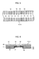
- the metal mold body 50 can be disassembled into four parts as shown in Fig. 8 .
- the metal mold body 50 is disassembled into a pair of large curved members 61 and 62, and a pair of small curved members 63 and 64. Both end surfaces 61a and 61b of the large curved member 61 is in tight contact with end surfaces 63a and 64a of the small curved members 63 and 64, and both end surfaces 62a and 62b of the other large curved member 62 is in tight contact with the other end surfaces 63b and 64b of the small curved members 63 and 64.
- Both the end surfaces 61a and 61b of the large curved member 61 are coincident with a flat plane parallel to the axis of the cylindrical metal mold body 50.
- both the end surfaces 62a and 62b of the large curved member 62 are coincident with a flat plane parallel to the axis of the cylindrical metal mold body 50.
- These flat planes are parallel to each other. Namely, the metal mold body 50 can be disassembled into four parts with the two parallel planes.
- the upper end of the metal mold body 50 is integrally fixed by a fixing member 65, and the lower end of the metal mold body 50 is integrally fixed by a fixing member 66.
- the fixing member 65 is an annular member having the same diameter as the metal mold body 50, and attached to the upper end of the metal mold body 50 by screws 67.
- the fixing member 66 is attached to the lower end of the metal mold body 50 by screws 68.
- the timing belt In the manufacturing process of the timing belt, in a state in which the metal mold body 50 is assembled through the fixing members 65 and 66, a fabric formed into a bag is put over an outer surface of the metal mold body 50, around which a rubber sheet (intermediate rubber layer) is wound. Then, a cord is wound around the rubber sheet, and further, material of the tooth rubber is wound over it. An intermediate fabric is wound around them, and after material of backing rubber is wound, a cylindrical bag rubber sheet is put over them.
- the metal mold body 50 is put into a vulcanizer, where the metal mold body 50 is heated and pressed. Due to this, the rubber is cured, and the metal mold body 50 is then taken from the vulcanizer.
- the fixing members 65 and 66 are removed from the metal mold body 50.
- the small curved members 63 and 64 are then displaced inward and removed, the large curved members 61 and 62 are moved inward, and a belt slab in which teeth and so on are formed, is separated from the metal mold body 50 and extracted.
- the belt slab is cut at a predetermined interval, so that endless timing belts are obtained.
- the metal mold body 50 is disassembled into four parts, but the disassembling structure of the metal mold body 50 is not limited to this. Namely, any structure, by which the belt slab can be extracted can be used, and the number of disassembling parts is unlimited. For example, the number of large curved members may be two, and the number of small curved members may be one.
- timing belts for a suction feeder were manufactured.
- Example 1 is shown in Fig. 9(a) , in which the tooth rubber 41 is laminated on the backing rubber 42, and the cords 44 are embedded in the tooth rubber 41.
- the flat surface 31 is formed at the center of the cross section, and the belt teeth 32 are formed on both sides.
- the surface of the tooth rubber 41 is covered with the fabric 36 as a whole.
- the fabric 36 is a special fabric having stretchable properties in both the longitudinal and lateral directions of the timing belt, similar to the embodiment described above.
- the details of each part of the timing belt of Example 1 are shown in Table 1 of Fig. 12 .
- Example 2 is shown in Fig. 9(b) , in which the intermediate rubber layer 45 of thickness 0.2mm is provided between the tooth rubber 41 and the fabric 36.
- the structures except for the intermediate rubber layer 45 are identical to those of Example 1. Namely, in Example 2, since the intermediate rubber layer 45 is provided, the flatness of the flat surface 31 is high compared to Example 1 where unevenness caused by the existence of the cords 44 can be seen on the flat surface 31, as shown in Fig. 9(a) . Note that the details of each part of the timing belt of Example 2 are shown in Table 1.
- Comparative example 1 is shown in Fig. 9(c) , in which a tooth rubber 72 is laminated on a backing rubber 71, and cords 73 are embedded in the tooth rubber 72.
- the backing rubber 71 and the tooth rubber are formed by castableurethane.
- a flat surface 74 is formed at the center of the cross section, and the belt teeth 75 are formed on both sides.
- the driving surface is not provided with a fabric, but is configured with the tooth rubber 72.
- Table 1 The details of each part of the timing belt of Comparative example 1 are shown in Table 1.
- Comparative example 2 is shown in Fig. 9(d) , in which a surface of the belt teeth 75 is covered with a fabric 76, and the tooth rubber 72 and a part of each cord 73 are exposed on the flat surface 74 due to a grinding process for the tooth surface.
- the backing rubber 71 and the tooth rubber 72 are NBR rubber, similarly to Examples 1 and 2.
- the fabric 76 is a normal fabric, which has a sufficient stretchable property in the longitudinal direction of the timing belt, but has little stretchable property in the lateral direction.
- Comparative example 3 has generally the same structure as Example 1, but the structure of the fabric 76 is different. Namely, in Comparative example 3, the fabric 76 is a normal fabric, which has a sufficient stretchable property in the longitudinal direction of the timing belt, but has little stretchable property in the lateral direction, similar to Comparative example 2. As shown in Fig. 9(e) , the belt tooth 75 has an imperfect molding, in which roundness occurs at a corner between the tip portion 75a and the tooth end portion 75d, and a corner between the tooth end portion 75d and the flat surface 74. Further, in the flat surface 74, the adhesiveness of the fabric to the tooth rubber is reduced, and unevenness caused by the cords 73 can be seen.
- timing belts were mounted on a test machine to conduct a suction test, by which a negative pressure generated in the suction chamber was measured.
- Fig. 10 shows a test machine used in the dustemission/heat-generation test.
- This test machine has two pulleys 81 and 82, between which a suction chamber 83 is disposed.
- a timing belt of the example or the comparative example was wound around the pulleys 81 and 82, and rotated while a negative pressure was generated on the flat surface of the timing belt by the suction chamber 83.
- the circumference length of the timing belt was 762mm, and the width was 38.1mm, but the suction hole 33 was not formed, different from the embodiment.
- the shape of the belt tooth was Type L, the pitch was 9.525mm, the tooth height was 1.91mm, and the number of teeth was 80. In the pulleys 81 and 82, the number of teeth was 24, and the number of rotations was 500 rpm.
- the set value (gauge pressure) of the suction pressure at the negative pressure source of the suction chamber 83 was -60kPa, and the length of the suction chamber 83 (i.e., dimension of the timing belt in the longitudinal direction) was 180mm.
- the timing belt was continuously run for one hour while the suction holes 84 of the suction chamber 83 were in contact with the flat surface of the timing belt to absorb the timing belt with the above-described set suction pressure, the temperature of the suction chamber 83 was measured, and the timing belt was then continuously run for 48 hours so that the dust emission conditions around the timing belt and the pulleys could be observed. This test result will be described later.
- Fig. 11 shows a test machine which was utilized for the sliding resistance test. While the structures of the pulleys 81 and 82 and the suction chamber 83 were the same as those of the dust-emission/heat-generation test, suction holes were formed at the center of the flat surface of the timing belt in the sliding resistance test. The suction holes were formed with a 19.05mm pitch along the longitudinal direction of the timing belt, and the diameter of the suction holes was 4mm. A film 85 was provided on the side of the back surface of the timing belt (the conveying surface 37 in the embodiment), and a force necessary for starting the film 85 to move together with the timing belt was measured. The other test conditions were the same as those of the dust-emission/heat-generation test.
- Table 2 shown in Fig. 13 indicates results of the dust-emission/heat-generation test, the sliding resistance test, the suction test, and the formability of the timing belt.
- the formability of the belt teeth was satisfactory.
- the timing belt of Example 1 had unevenness with the same pitch as that of the cords on the flat surface, because of a load (i.e., winding tension) applied to the fabric by the cord during winding of the cord.
- the timing belt of Example 2 did not have unevenness on the flat surface due to the provision of the intermediate rubber layer.
- the formability of the belt tooth was satisfactory, the flatness of the flat surface was good, and the suction property showed a similar result as that of Example 2.
- urethane in which the coefficient of friction of the flat surface was high, was directly slidingly in contact with the suction holes of the suction chamber, heat was generated by friction, and sliding resistance was large. Namely, the temperature after running continuously for one hour was 65°C, which was too high, and the sliding resistance was 2550g (25.0N). Further, abrasion (or dust) could be seen, and thus, it was understood that the timing belt was not practical.
- the timing belt of Comparative example 2 had satisfactory formability of the belt teeth, a part of the cord was exposed on the flat surface due to the grinding process of the tooth surface, and burr was generated on the flat surface. Due to this, the negative pressure generated in the suction chamber was -58kPa, which was mostly satisfactory, but the negative pressure was largely dispersed and not stable. Namely, although the temperature after running continuously for one hour was 50°C, the sliding resistance was 1500g (14.7N), which was rather large, and further, abrasion (or dust) could be seen, and thus, it was understood that the timing belt was not practical.
- the belt teeth were rounded, and the formability was poor. Further, the timing belt had unevenness with the same pitch as that of the cords on the flat surface, and the unevenness was large. Due to this, the negative pressure generated in the suction chamber was -50kPa, which was largely dispersed and not stable, and the practicability was poor. Note that the temperature after running continuously for one hour was 41°C, and the sliding resistance was 1000g (9.8N); both the temperature and the sliding resistance were satisfactory, and abrasion (or dust) could not be seen.
Landscapes
- Engineering & Computer Science (AREA)
- Mechanical Engineering (AREA)
- General Engineering & Computer Science (AREA)
- Textile Engineering (AREA)
- Belt Conveyors (AREA)
- Delivering By Means Of Belts And Rollers (AREA)
- Folding Of Thin Sheet-Like Materials, Special Discharging Devices, And Others (AREA)
- Advancing Webs (AREA)
Abstract
Description
- The present invention relates to a packaging machine for supplying contents to a pillow-shaped film pouch, and more particularly, relates to a timing belt for a suction feeder, used for conveying film which is shaped in a cylindrical form.
- Conventionally, such a packaging machine is constructed in such a manner that a cylindrical film pouch can be conveyed while maintaining its cylindrically inflated state so that contents such as cakes can be filled therein. In order to perform such a conveying process, a pair of timing belts is disposed along the conveying direction of the cylindrical film pouch, and these timing belts are formed with suction holes so that a negative pressure is applied in order to suck and inflate the cylindrical film pouch. As a timing belt provided with suction holes, one disclosed in
Patent Document 1 is known, in which the suction holes are formed in a flat area of the central portion of the timing belt, in which belt teeth are not formed, for example. - PATENT DOCUMENT 1: Unexamined Utility Model Publication No. (HEI)
7-38021 - For forming the flat area at the central portion of the timing belt in order to form the suction holes, usually, a method is adopted, in which belt teeth of the central portion are shaved off. However, due to such a machining, a layer such as rubber, urethane, or cords is exposed in the flat area. In a timing belt, a surface on which belt teeth are formed is not only engaged with a drive pulley, but also slidingly contacted with a suction chamber for sucking the cylindrical film pouch toward the belt. Therefore, in the flat area in which the rubber and so on is exposed, not only does a problem occur in which wear debris capable of contaminating the packing machine is generated due to the friction with the suction chamber while running of the timing belt, but another problem also occurs in which sliding resistance becomes large enough to generate heat, and a load of a motor, which is a power source, becomes high to increase the electrical consumption.
- The object of the invention is to provide a timing belt for a suction feeder, in which wear debris is not generated and sliding resistance is suppressed as much as possible to prevent the generation of heat, so that the load of the power source can be reduced.
- The suction feeder timing belt according to the present invention has a feature which comprises a planar conveying surface; a driving surface positioned opposite to the conveying surface, with the driving surface having a flat surface extending in the longitudinal direction of the timing belt at the center portion in the lateral direction of the timing belt, and the driving surface having belt teeth formed at a constant interval in the longitudinal direction on both of the outer sides of the center portion; and a fabric covering the whole of the driving surface, with the fabric being stretchable in both the longitudinal and lateral directions of the timing belt.
- Preferably, a cord is embedded in tooth rubber forming the driving surface, and an intermediate rubber layer is provided between the fabric and the cord. Due to the intermediate rubber layer, flatness of the flat surface is ensured in spite of the provision of the cords.
- The fabric is a woven fabric, for example. The stretch ratio of the fabric is greater than or equal to 35% in the longitudinal direction, for example, and the stretch ratio of the fabric is greater than or equal to 10% in the lateral direction, for example. Preferably, the stretch ratio of the fabric is greater than or equal to 80% in the longitudinal direction, and the stretch ratio of the fabric is greater than or equal to 50% in the lateral direction.
- Preferably, the fabric covers the flat surface, a tooth bottom portion formed between two adjacent belt teeth, a tip portion of the belt tooth, a tooth side portion formed between the tip portion and the tooth bottom portion, and a tooth end portion positioned on the flat-surface side of the belt tooth.
- The flat surface is configured with suction holes, which are drilled at a predetermined interval in the longitudinal direction and penetrate through the conveying surface. This is for applying a negative pressure onto an outer surface of the cylindrical film pouch conveyed by the timing belt.
- According to the suction feeder timing belt of the present invention, wear debris is not generated and sliding resistance is suppressed as much as possible to prevent the generation of heat when being used in a packaging machine which feeds a packaging film pouch. Further, not only can the load of the power source be reduced, but also a stable negative pressure is always generated. Furthermore, since the fabric has elasticity both in the longitudinal direction and the lateral direction of the timing belt, adhesiveness of the fabric with respect to the tooth rubber is improved, by which the fabric is prevented from separating in an early stage, and is prevented from being imperfectly molded.
-
-
Fig. 1 is a view illustrating a general construction of a packaging machine, which uses the suction feeder timing belt, which is an embodiment of the present invention. -
Fig. 2 is a perspective view illustrating a driving surface of the timing belt. -
Fig. 3 is a plan view of the timing belt viewed from the conveying surface side. -
Fig. 4 is a side view of the timing belt. -
Fig. 5 is a bottom view of the timing belt viewed from the driving surface side. -
Fig. 6 is a cross-sectional view on VI-VI line ofFig. 4 . -
Fig. 7 is a perspective view illustrating a mold. -
Fig. 8 is a plan view illustrating a disassembled state of a mold body. -
Fig. 9 is a cross-sectional view illustrating an example and a comparative example of the timing belt. -
Fig. 10 is a schematic view illustrating a test machine which performs a dust-emission/heat-generation test. -
Fig. 11 is a schematic view illustrating a test machine which performs a sliding resistance test. -
Fig. 12 is a table indicating specifications of the timing belt in the example and the comparative example. -
Fig. 13 is a table indicating an experiment result using the example and the comparative example. -
- 30: driving surface
- 31: flat surface
- 32: belt teeth
- 36: fabric
- 37: conveying surface
- 41: tooth rubber
- 42: backing rubber
- 45: intermediate rubber layer
- In the following, a timing belt for a suction feeder, which is an embodiment of the present invention, will be described with reference to the drawings.
-
Fig. 1 shows a general construction of a packaging machine, which uses the timing belt. This packaging machine is configured such that, while forming sheet-shaped film F into a cylinder, contents A such as cakes are supplied to the film pouch F. The lower end B of the cylindrically formed film pouch F is sealed, and under this condition, the contents A are supplied into the cylindrically formed film pouch F. The upper portion C of the cylindrically formed film pouch F, in which the contents A are filled, is sealed and cut at the lower portion of the packaging machine, and the pillow-shaped film pouch D is conveyed to the next process. - A
cylindrical guide member 11, extending in vertical direction, is disposed at the center of the packaging machine, and a truncatedconical hopper 12 diverging upper side is provided at the upper end of theguide member 11.Endless timing belts guide member 11. Thetiming belts guide member 11 with enough space in between to pass the film F. Thetiming belt 13 is wound aroundpulleys timing belt 14 is wound aroundpulleys pulleys timing belt guide member 11 move downward in the drawing. - A
suction chamber 21 is provided between thepulleys timing belt 13. Similarly, asuction chamber 22 is provided between thepulleys timing belt 14. Thesuction chambers timing belts suction chambers - The film F is sheet-shaped above the
hopper 12, and is deformed into a cylinder covering the outer surface of theguide member 11 by a forming machine (not shown). Edge portions of the film F, along the axis of theguide member 11, are adhered to each other, and the lower end B is sealed. In this process, the cylindrical shape of the film F is kept due to the negative pressure supplied by thesuction chambers timing belts hopper 12 are accumulated in the lower part of the film F. When the film F filled with the contents A moves below theguide member 11, the upper end C is sealed and cut at the position of the broken line E. -
Fig. 2 shows an inner surface or a drivingsurface 30 of thetiming belts flat surface 31 is formed extending in the longitudinal direction of thetiming belts timing belts teeth 32 are formed at a constant interval in the longitudinal direction of the timing belt on both of the outer sides of the center portion. Theflat surface 31 is configured with suction holes 33. The suction holes 33 are drilled at a predetermined interval in the longitudinal direction and penetrate through the conveyingsurface 37, which is opposite to the drivingsurface 30. Atip portion 32a of thebelt teeth 32 is an approximately flat surface, and atooth bottom portion 34 formed between the twoadjacent belt teeth 32 is a flat surface slightly greater than thetip portion 32a.Tooth side portions tip portion 32a and thetooth bottom portion 34 are inclined. On the other hand, atooth end portion 32d positioned at theflat surface 31 side of thebelt tooth 32 is vertical to the flat surface 31 (seeFig. 6 ). - The whole of the driving
surface 30 is covered with afabric 36. Namely, in the drivingsurface 30, thefabric 36 covers theflat surface 31, thetooth bottom portion 34, thetip portion 32a of thebelt teeth 32, thetooth side portions tooth end portion 32d. In other words, outer side surfaces 35 of thetiming belts inner wall 33a of the suction holes 33 are not covered with thefabric 36, leaving the rubber exposed in those areas. -
Fig. 3 is a plan view of thetiming belts surface 37 side.Fig. 4 is a side view of thetiming belts Fig. 5 is a bottom view of thetiming belts surface 37 is flat, anelliptical recess 38 is formed around thesuction hole 33, so that the surrounding portion is slightly indented in the conveyingsurface 37. Thesuction hole 33 is circular, and is positioned at the center of therecess 38. - With reference to
Figs. 2 and6 , the layered structure of thetiming belts tooth rubber 41 forming the drivingsurface 30 of thetiming belts rubber 42 forming the conveyingsurface 37 is soft NBR rubber, in which the hardness is 61JIS-A, for example. However, depending upon the application, the timing belt may be formed only with tooth rubber, so that one surface of the tooth rubber can be a driving surface, and the other surface of the tooth rubber can be a conveying surface. Thefabric 36 is woven fabric or knitted fabric, which is stretchable in both the longitudinal and lateral directions of the timing belts.Glass cords 44 composed of E-glass are provided in thetooth rubber 41, and anintermediate rubber layer 45 is provided between thefabric 36 and theglass cords 44. - When the
fabric 36 is a woven fabric, various kinds of woven fabric including plain weave, twill weave or satin weave can be utilized. Regarding warp and weft forming the woven fabric, when both of the warp and the weft are stretchable, thefabric 36 is disposed on the drivingsurface 30 of thetiming belts timing belts fabric 36 is disposed on the drivingsurface 30 of thetiming belts timing belts timing belts - In the
fabric 36, the stretch ratio is different in the lateral direction and the longitudinal direction of thetiming belts fabric 36, in which tensile force of 4.0kgf per 1-inch width acts on thetiming belts fabric 36, in which tensile force of 4.0kgf per 1-inch width acts on thetiming belts - If the stretch ratio of the
fabric 36, in which tensile force of 4.0kgf per 1-inch width acts on thetiming belts fabric 36, in which tensile force of 4.0kgf per 1-inch width acts on thetiming belts belt teeth 32 when manufacturing the belt is obtained, and the flatness of theflat surface 31 is ensured. - If the stretch ratio of the fabric, in which tensile force of 4.0kgf per 1-inch width acts on the
timing belts fabric 36, in which tensile force of 4.0kgf per 1-inch width acts on thetiming belts belt teeth 32 when manufacturing the belt is obtained, and the flatness of theflat surface 31 is further improved, by which the serviceable life of the timing belt for a suction feeder is prolonged. Further, a timing belt having such a stretch ratio can be used as a trapezoidaltooth profile timing belt of Types XH, XXH, and so on. - Conversely, if the stretch ratio of the fabric in the lateral direction of the
timing belts fabric 36, which covers thetooth end portion 32d of thebelt teeth 32 and thetip portion 32a close to thetooth end portion 32d, cannot be formed sufficiently along the shape of the metal mold when manufacturing the belt. If the stretch ratio of the fabric in the longitudinal direction of thetiming belts fabric 36, which covers thetooth side portions belt teeth 32 and thetip portion 32a close to thetooth side portions belt teeth 32, and poor quality, in which thetooth rubber 41 passes through thefabric 36 and exudes onto a surface of thebelt teeth 32, will occur. Further, if thefabric 36 covering theflat surface 31 and thetooth bottom portion 34 is drawn in a belt-lateral direction or a belt-longitudinal direction when manufacturing the belt, the adhesive property of thefabric 36 with respect to thetooth rubber 41 can be lowered, so that thefabric 36 becomes separated from thetooth rubber 41 at an early stage of usage of the belt, or the flatness of theflat surface 31 deteriorates. - As an example of a structure of woven fabric, one of the warp or the weft is wooly yarn of nylon, another is urethane elastic yarn, which is configured by winding nylon yarn around urethane core yarn. As the other example, both of the warp and the weft may be configured using wooly yarn of nylon. Further, both of the warp and the weft may be configured by textured yarn obtained using crimping, Taslan process (trade mark), interlacing process, covering process, or a combination thereof. In case of fabric using filament yarn for one of the warp or the weft, the fabric may be bias-cut so that the fabric can be stretchable in both the longitudinal and lateral directions of the timing belt. Note that the fabric can be reinforced by impregnating RFL process liquid, rubber cement, and so on, in the fabric.
- When the
fabric 36 is a knit fabric, a weft-knitted fabric and a warp-knitted fabric can be used. As a weft-knitted fabric, various kinds of weft-knitted fabric, including a flat-knitted fabric, a rib-stitched fabric, an interlock-knitted fabric, a purl-stitched fabric, and so on, can be used. On the other hand, as a warp-knitted fabric, a Tricot-knitted fabric, a Russel-knitted fabric, a Milanese-knitted fabric, and so on, can be used. The stretchable property of these knitted fabrics is the same as those of the woven fabric described above. - The
intermediate rubber layer 45 can be formed by pressing a rubber sheet onto thefabric 36 to adhere them, or can be formed by coating thefabric 36 with a rubber layer. As another example, theintermediate rubber layer 45 can be configured by winding a rubber sheet around thefabric 36. In any case, the thickness of theintermediate rubber layer 45 is preferably greater than 0.2mm. According to such a structure, when manufacturing the belt, a load (i.e., winding tension) applied to the fabric surface, which occurs by winding a cord around a jacket attached to the metal mold, can be absorbed by the intermediate rubber layer. Due to this, the load directly acting on the fabric from the cord can be reduced, so that the flatness of the flat surface is improved. - The
tooth rubber 41, the backingrubber 42, and theintermediate rubber layer 45 can be made using various kinds of rubber in accordance with their purposes, and may be the same kind of rubber or different kinds of rubbers. The different kinds of rubber that can be used include NBR rubber, HNBR rubber, CR rubber, urethane rubber, fluoro rubber, natural rubber, CSM rubber, EPDM rubber, EPM rubber, SBR rubber, BR rubber, and so on. - The
glass cords 44 are overcoat-processed with RFL/rubber cement solution, so that adhesiveness to thetooth rubber 41 is enhanced. Theglass cords 44 are positioned close to thetooth bottom portion 34 and theflat surface 31, where theglass cords 44 are covered with thefabric 36. Since the suction holes 33 are formed, there are nocords 44 at the portions corresponding to the suction holes 33. However, a portion of theflat surface 31 between adjacent suction holes 33 is reinforced by thefabric 36, and thereby, the strength of the portion is sufficiently ensured. Note that thecords 44 are not limited to E-glass, instead various kinds of glass fiber such as U-glass can be used. Further, thecords 44 can be configured by aramid fiber, or carbon. - An operation of the timing belt of the present embodiment will be described below. In the feeding process of the film F, the film F is moved, while maintaining its cylindrical shape, by the
timing belts timing belts belt teeth 32, and theflat surface 31 is slidingly contacted with thesuction chambers fabric 36, wear debris is not generated in spite of the sliding contact of the flat surface with thesuction chambers flat surface 31 is minimized, the load of the driving source of thetiming belts - Further, in the embodiment, since the
intermediate rubber layer 45 is provided, unevenness, which is caused by the shape of thecords 44, is not generated in theflat surface 31, so that the flatness of theflat surface 31 is ensured. Therefore, contact of theflat surface 31 with thesuction chambers suction chambers Fig. 1 ). - The shape of the driving
surface 30, which thefabric 34 covers, is complicated, and thetiming belts flat surface 31 along the longitudinal direction at the central portion, while thebelt teeth 32 are formed at a constant interval at both sides of theflat surface 31. As described above, thefabric 36 is stretchable in both the longitudinal and lateral directions of thetiming belts fabric 36 is tightly adhered on the whole surface of thebelt teeth 32, and roundness does not occur at corners between thetip portion 32a and thetooth side portions tip portion 32a and thetooth end portion 32d, a corner between thetip portion 32a and thetooth bottom portion 34, and a corner between thetooth end portion 32d and theflat surface 31. Namely, the adhesiveness of the fabric to the tooth rubber is improved, the fabric does not separate from the rubber, and is prevented from causing imperfect molding. - The backing
rubber 42 has preferably a large coefficient of friction for feeding the film F, and is preferably made of material having good abrasion resistance properties. And the surface of the backingrubber 42 has preferably a low surface roughness in order to obtain a large friction force while ensuring the contact area with the film F. Accordingly, the conveyingsurface 37 is grinded in a manufacturing process to become as close to a mirror surface as possible. - With reference to
Figs. 2 ,7 , and8 , a structure of the metal mold for manufacturing the timing belt is described below. - A
metal mold body 50 is cylindrical, and is configured on an outer surface with a number of recessedportions 51 extending in the axial direction and threeannular surfaces 52 extending in the circular direction. A rectangularflat portion 53 is formed between the two adjacent recessedportions 51. The recessedportions 51 correspond to thebelt teeth 32, and the rectangularflat portion 53 corresponds to thetooth bottom portion 34. Theannular surface 52 corresponds to theflat surface 31. Theannular surface 52 and the rectangularflat portion 53 are coincident with the cylindrical outer surface, and the recessedportion 51 is indented from the outer surface by the height of thebelt tooth 32. - In the embodiment, the
metal mold body 50 can be disassembled into four parts as shown inFig. 8 . Namely, themetal mold body 50 is disassembled into a pair of largecurved members curved members end surfaces curved member 61 is in tight contact withend surfaces curved members end surfaces curved member 62 is in tight contact with the other end surfaces 63b and 64b of the smallcurved members curved member 61 are coincident with a flat plane parallel to the axis of the cylindricalmetal mold body 50. Similarly, both the end surfaces 62a and 62b of the largecurved member 62 are coincident with a flat plane parallel to the axis of the cylindricalmetal mold body 50. These flat planes are parallel to each other. Namely, themetal mold body 50 can be disassembled into four parts with the two parallel planes. - In a state in which the large
curved members curved members metal mold body 50 is integrally fixed by a fixingmember 65, and the lower end of themetal mold body 50 is integrally fixed by a fixingmember 66. The fixingmember 65 is an annular member having the same diameter as themetal mold body 50, and attached to the upper end of themetal mold body 50 byscrews 67. Similarly, the fixingmember 66 is attached to the lower end of themetal mold body 50 byscrews 68. - In the manufacturing process of the timing belt, in a state in which the
metal mold body 50 is assembled through the fixingmembers metal mold body 50, around which a rubber sheet (intermediate rubber layer) is wound. Then, a cord is wound around the rubber sheet, and further, material of the tooth rubber is wound over it. An intermediate fabric is wound around them, and after material of backing rubber is wound, a cylindrical bag rubber sheet is put over them. In this state, themetal mold body 50 is put into a vulcanizer, where themetal mold body 50 is heated and pressed. Due to this, the rubber is cured, and themetal mold body 50 is then taken from the vulcanizer. - After cooling the
metal mold body 50, the fixingmembers metal mold body 50. The smallcurved members curved members metal mold body 50 and extracted. The belt slab is cut at a predetermined interval, so that endless timing belts are obtained. - Note that, in the example shown in
Figs. 7 and8 , themetal mold body 50 is disassembled into four parts, but the disassembling structure of themetal mold body 50 is not limited to this. Namely, any structure, by which the belt slab can be extracted can be used, and the number of disassembling parts is unlimited. For example, the number of large curved members may be two, and the number of small curved members may be one. - As Examples and Comparative examples, timing belts for a suction feeder were manufactured. Example 1 is shown in
Fig. 9(a) , in which thetooth rubber 41 is laminated on thebacking rubber 42, and thecords 44 are embedded in thetooth rubber 41. In thetooth rubber 41, theflat surface 31 is formed at the center of the cross section, and thebelt teeth 32 are formed on both sides. The surface of thetooth rubber 41 is covered with thefabric 36 as a whole. Thefabric 36 is a special fabric having stretchable properties in both the longitudinal and lateral directions of the timing belt, similar to the embodiment described above. The details of each part of the timing belt of Example 1 are shown in Table 1 ofFig. 12 . - Example 2 is shown in
Fig. 9(b) , in which theintermediate rubber layer 45 of thickness 0.2mm is provided between thetooth rubber 41 and thefabric 36. The structures except for theintermediate rubber layer 45 are identical to those of Example 1. Namely, in Example 2, since theintermediate rubber layer 45 is provided, the flatness of theflat surface 31 is high compared to Example 1 where unevenness caused by the existence of thecords 44 can be seen on theflat surface 31, as shown inFig. 9(a) . Note that the details of each part of the timing belt of Example 2 are shown in Table 1. - Comparative example 1 is shown in
Fig. 9(c) , in which atooth rubber 72 is laminated on abacking rubber 71, andcords 73 are embedded in thetooth rubber 72. The backingrubber 71 and the tooth rubber are formed by castableurethane. In thetooth rubber 72, aflat surface 74 is formed at the center of the cross section, and thebelt teeth 75 are formed on both sides. The driving surface is not provided with a fabric, but is configured with thetooth rubber 72. The details of each part of the timing belt of Comparative example 1 are shown in Table 1. - Comparative example 2 is shown in
Fig. 9(d) , in which a surface of thebelt teeth 75 is covered with afabric 76, and thetooth rubber 72 and a part of eachcord 73 are exposed on theflat surface 74 due to a grinding process for the tooth surface. As shown in Table 1, the backingrubber 71 and thetooth rubber 72 are NBR rubber, similarly to Examples 1 and 2. Thefabric 76 is a normal fabric, which has a sufficient stretchable property in the longitudinal direction of the timing belt, but has little stretchable property in the lateral direction. - Comparative example 3 has generally the same structure as Example 1, but the structure of the
fabric 76 is different. Namely, in Comparative example 3, thefabric 76 is a normal fabric, which has a sufficient stretchable property in the longitudinal direction of the timing belt, but has little stretchable property in the lateral direction, similar to Comparative example 2. As shown inFig. 9(e) , thebelt tooth 75 has an imperfect molding, in which roundness occurs at a corner between thetip portion 75a and thetooth end portion 75d, and a corner between thetooth end portion 75d and theflat surface 74. Further, in theflat surface 74, the adhesiveness of the fabric to the tooth rubber is reduced, and unevenness caused by thecords 73 can be seen. - A dust-emission/heat-generation test and a sliding resistance test were carried out on the timing belts. Further, the timing belts were mounted on a test machine to conduct a suction test, by which a negative pressure generated in the suction chamber was measured.
-
Fig. 10 shows a test machine used in the dustemission/heat-generation test. This test machine has twopulleys suction chamber 83 is disposed. A timing belt of the example or the comparative example was wound around thepulleys suction chamber 83. - The circumference length of the timing belt was 762mm, and the width was 38.1mm, but the
suction hole 33 was not formed, different from the embodiment. The shape of the belt tooth was Type L, the pitch was 9.525mm, the tooth height was 1.91mm, and the number of teeth was 80. In thepulleys suction chamber 83 was -60kPa, and the length of the suction chamber 83 (i.e., dimension of the timing belt in the longitudinal direction) was 180mm. The suction holes 84 of 13.5mm in width, which corresponds to the 15mm in width of the flat surface of the timing belt, were formed at the center of the surface of the timing belt side of thesuction chamber 83. - After the timing belt was continuously run for one hour while the suction holes 84 of the
suction chamber 83 were in contact with the flat surface of the timing belt to absorb the timing belt with the above-described set suction pressure, the temperature of thesuction chamber 83 was measured, and the timing belt was then continuously run for 48 hours so that the dust emission conditions around the timing belt and the pulleys could be observed. This test result will be described later. -
Fig. 11 shows a test machine which was utilized for the sliding resistance test. While the structures of thepulleys suction chamber 83 were the same as those of the dust-emission/heat-generation test, suction holes were formed at the center of the flat surface of the timing belt in the sliding resistance test. The suction holes were formed with a 19.05mm pitch along the longitudinal direction of the timing belt, and the diameter of the suction holes was 4mm. Afilm 85 was provided on the side of the back surface of the timing belt (the conveyingsurface 37 in the embodiment), and a force necessary for starting thefilm 85 to move together with the timing belt was measured. The other test conditions were the same as those of the dust-emission/heat-generation test. - Table 2 shown in
Fig. 13 indicates results of the dust-emission/heat-generation test, the sliding resistance test, the suction test, and the formability of the timing belt. - Regarding the dust-emission test, abrasion (or dust) could not be seen both in Examples 1 and 2, and a satisfactory result was obtained. In the heat-generation test, the temperature before the test was 26.7°C, and the temperature after running one hour continuously was 41°C in both of Examples 1 and 2, which was a satisfactory result. On the other hand, regarding the sliding resistance test, a relatively low sliding resistance of 1000g (9.8N) was measured in both Examples 1 and 2.
- In both the timing belts of Examples 1 and 2, the formability of the belt teeth was satisfactory. In the manufacturing process, the timing belt of Example 1 had unevenness with the same pitch as that of the cords on the flat surface, because of a load (i.e., winding tension) applied to the fabric by the cord during winding of the cord. Conversely, the timing belt of Example 2 did not have unevenness on the flat surface due to the provision of the intermediate rubber layer. Due to the difference of the presence or absence of the unevenness, there was a small difference in the suction property, in which the negative pressure generated in the suction chamber was -58kPa in Example 1, with variation detected in the measured value, while the negative pressure generated in the suction chamber was -60kPa in Example 2, without any noticeable variation in the measured value, and thus a stable and very satisfactory result was obtained. Namely, in the timing belt of Example 2, the suction pressure of the negative pressure source supplied by the suction chamber did not decrease, and was transmitted to the timing belt at full pressure.
- Conversely, in the timing belt of Comparative example 1, the formability of the belt tooth was satisfactory, the flatness of the flat surface was good, and the suction property showed a similar result as that of Example 2. However, since urethane, in which the coefficient of friction of the flat surface was high, was directly slidingly in contact with the suction holes of the suction chamber, heat was generated by friction, and sliding resistance was large. Namely, the temperature after running continuously for one hour was 65°C, which was too high, and the sliding resistance was 2550g (25.0N). Further, abrasion (or dust) could be seen, and thus, it was understood that the timing belt was not practical.
- Although the timing belt of Comparative example 2 had satisfactory formability of the belt teeth, a part of the cord was exposed on the flat surface due to the grinding process of the tooth surface, and burr was generated on the flat surface. Due to this, the negative pressure generated in the suction chamber was -58kPa, which was mostly satisfactory, but the negative pressure was largely dispersed and not stable. Namely, although the temperature after running continuously for one hour was 50°C, the sliding resistance was 1500g (14.7N), which was rather large, and further, abrasion (or dust) could be seen, and thus, it was understood that the timing belt was not practical.
- In the timing belt of Comparative example 3, the belt teeth were rounded, and the formability was poor. Further, the timing belt had unevenness with the same pitch as that of the cords on the flat surface, and the unevenness was large. Due to this, the negative pressure generated in the suction chamber was -50kPa, which was largely dispersed and not stable, and the practicability was poor. Note that the temperature after running continuously for one hour was 41°C, and the sliding resistance was 1000g (9.8N); both the temperature and the sliding resistance were satisfactory, and abrasion (or dust) could not be seen.
Claims (7)
- A timing belt, which is endless and used for a suction feeder, the timing belt comprising:a planar conveying surface;a driving surface positioned opposite to the conveying surface, the driving surface having a flat surface extending in the longitudinal direction of the timing belt at the center portion in the lateral direction of the timing belt, the driving surface having belt teeth formed at a constant interval in the longitudinal direction on both of the outer sides of the center portion; anda fabric covering the whole of the driving surface;the fabric being stretchable in both the longitudinal and lateral directions of the timing belt.
- The timing belt for a suction feeder, according to claim 1, further comprising a cord embedded in tooth rubber forming the driving surface, and an intermediate rubber layer provided between the fabric and the cord.
- The timing belt for a suction feeder, according to claim 1 or 2, wherein the fabric is a woven fabric.
- The timing belt for a suction feeder, according to claim 1 or 2, wherein a stretch ratio of the fabric is greater than or equal to 35% in the longitudinal direction, and a stretch ratio of the fabric is greater than or equal to 10% in the lateral direction.
- The timing belt for a suction feeder, according to claim 4, wherein the stretch ratio of the fabric is greater than or equal to 80% in the longitudinal direction, and the stretch ratio of the fabric is greater than or equal to 50% in the lateral direction.
- The timing belt for a suction feeder, according to claim 1 or 2, wherein the fabric covers the flat surface, a tooth bottom portion formed between two adjacent belt teeth, a tip portion of the belt tooth, a tooth side portion formed between the tip portion and the tooth bottom portion, and a tooth end portion positioned on the flat-surface side of the belt tooth.
- The timing belt for a suction feeder, according to claim 1 or 2, wherein the flat surface is configured with suction holes, which are drilled at a predetermined interval in the longitudinal direction and penetrate through the conveying surface.
Applications Claiming Priority (2)
| Application Number | Priority Date | Filing Date | Title |
|---|---|---|---|
| JP2012239368A JP5873417B2 (en) | 2012-10-30 | 2012-10-30 | Timing belt for suction feeder |
| PCT/JP2013/052681 WO2014069000A1 (en) | 2012-10-30 | 2013-02-06 | Timing belt for suction feeder |
Publications (3)
| Publication Number | Publication Date |
|---|---|
| EP2916035A1 true EP2916035A1 (en) | 2015-09-09 |
| EP2916035A4 EP2916035A4 (en) | 2016-07-27 |
| EP2916035B1 EP2916035B1 (en) | 2021-07-07 |
Family
ID=50626944
Family Applications (1)
| Application Number | Title | Priority Date | Filing Date |
|---|---|---|---|
| EP13851269.4A Active EP2916035B1 (en) | 2012-10-30 | 2013-02-06 | Timing belt for suction feeder |
Country Status (9)
| Country | Link |
|---|---|
| US (1) | US9321592B2 (en) |
| EP (1) | EP2916035B1 (en) |
| JP (1) | JP5873417B2 (en) |
| KR (1) | KR102027390B1 (en) |
| CN (1) | CN104813064A (en) |
| IN (1) | IN2015KN00662A (en) |
| PH (1) | PH12015500946B1 (en) |
| TW (1) | TWI608978B (en) |
| WO (1) | WO2014069000A1 (en) |
Families Citing this family (12)
| Publication number | Priority date | Publication date | Assignee | Title |
|---|---|---|---|---|
| FR3000530B1 (en) * | 2012-12-28 | 2015-07-10 | Bobst Lyon | TRANSPORT STRIP OF PLATE ELEMENTS AND TRANSFORMATION MACHINE COMPRISING SUCH A TRANSPORT STRIP |
| JP6352724B2 (en) * | 2014-08-06 | 2018-07-04 | ニッタ株式会社 | Endless flat belt and manufacturing method thereof |
| US9676555B2 (en) | 2015-04-17 | 2017-06-13 | F.N. Sheppard & Company | Co-formed conveyor belt apparatus and process |
| JP6635777B2 (en) * | 2015-12-09 | 2020-01-29 | Nok株式会社 | Method of manufacturing suction conveyance belt and suction conveyance belt |
| US9950866B2 (en) * | 2016-03-24 | 2018-04-24 | Advanced Flexible Composites, Inc. | Apparatus and method for driving low coefficient of friction belting |
| CN106276048A (en) * | 2016-08-18 | 2017-01-04 | 联诺欧机械科技江苏有限公司 | A kind of sucker belt |
| CN106628824A (en) * | 2016-10-11 | 2017-05-10 | 周峰 | Integral type anti-crack conveyor belt |
| JP7228953B2 (en) * | 2017-12-27 | 2023-02-27 | ニッタ株式会社 | conveyor belt |
| US12030723B2 (en) * | 2020-11-04 | 2024-07-09 | Contitech Transportbandsysteme Gmbh | Impact absorbing conveyor belt |
| US11634564B2 (en) * | 2021-03-22 | 2023-04-25 | Contitech Transportbandsysteme Gmbh | High heat and oil resistant conveyor belt |
| CN116714943A (en) * | 2023-05-05 | 2023-09-08 | 江苏新联达制带科技有限公司 | PU anti-aging conveyer belt |
| CN117125404B (en) * | 2023-10-24 | 2024-01-30 | 四川托璞勒科技股份有限公司 | Negative pressure device and conveying mechanism |
Family Cites Families (45)
| Publication number | Priority date | Publication date | Assignee | Title |
|---|---|---|---|---|
| US3580767A (en) * | 1969-03-28 | 1971-05-25 | Uniroyal Inc | Method of making a toothed drive belt with an abrasion resistant urethane coating on the transmission surface |
| NL163607C (en) * | 1969-04-14 | 1980-09-15 | Pirelli | TOOTHED DRIVE BELT. |
| GB1287844A (en) * | 1969-07-03 | 1972-09-06 | Stolle Corp | |
| BE817067A (en) * | 1973-07-16 | 1974-10-16 | CARRYING BELT | |
| US3981206A (en) * | 1975-08-20 | 1976-09-21 | Dayco Corporation | Endless power transmission belt |
| US4027545A (en) * | 1976-03-19 | 1977-06-07 | Dayco Corporation | Endless power transmission belt and method of making same |
| US4137787A (en) * | 1977-11-07 | 1979-02-06 | Dayco Corporation | Emergency stretch belt |
| US4311474A (en) * | 1979-09-14 | 1982-01-19 | Dayco Corporation | Synchronous belt and method for making the same |
| US4533420A (en) * | 1982-05-17 | 1985-08-06 | Dayco Corporation | Toothed belt |
| JPS58178545U (en) | 1982-05-25 | 1983-11-29 | 本田技研工業株式会社 | Power transmission belt |
| JPS6163054U (en) * | 1984-09-29 | 1986-04-28 | ||
| JPH063244B2 (en) * | 1986-07-10 | 1994-01-12 | 東レ株式会社 | Toothed belt |
| JP2885882B2 (en) * | 1990-05-14 | 1999-04-26 | バンドー化学株式会社 | Transmission belt |
| JPH04260516A (en) * | 1991-02-14 | 1992-09-16 | Bridgestone Corp | Tire constituting member transport device |
| JPH06319443A (en) | 1991-04-12 | 1994-11-22 | Yamamoto Shokuhin Kogyo Kk | Production of pickle |
| CA2067517A1 (en) * | 1991-04-30 | 1992-10-31 | Akinori Fujiwara | Synchronous belt |
| JP2500762B2 (en) | 1993-06-29 | 1996-05-29 | 日本電気株式会社 | Integrated circuit cooling structure |
| JPH0738021U (en) * | 1993-12-22 | 1995-07-14 | 三ツ星ベルト株式会社 | Wide Toothed Belt for Transport |
| JPH07208557A (en) * | 1994-01-13 | 1995-08-11 | Bando Chem Ind Ltd | Toothed belt |
| JPH07217704A (en) * | 1994-02-04 | 1995-08-15 | Bando Chem Ind Ltd | Toothed belt |
| US5609243A (en) * | 1994-12-28 | 1997-03-11 | Mitsuboshi Belting Ltd. | Toothed conveying belt |
| SE504820C2 (en) * | 1995-09-08 | 1997-04-28 | Bertil Wahren | Conveyor |
| JP3366787B2 (en) | 1995-10-20 | 2003-01-14 | ノーリツ鋼機株式会社 | Photosensitive material suction and transport device |
| GB2314398B (en) * | 1996-06-20 | 2001-02-14 | Unitta Co Ltd | Toothed belt |
| US5911307A (en) * | 1996-10-31 | 1999-06-15 | Burrel Leder Beltech, Inc. | Conveyor belt and method of manufacturing |
| DE19823948A1 (en) * | 1998-05-28 | 1999-12-02 | Voith Sulzer Papiermasch Gmbh | Endless band |
| AU9595798A (en) * | 1998-09-29 | 2000-04-17 | Goodyear Tire And Rubber Company, The | Synchronous drive belt with scaffold stretch fabric |
| JP2000213602A (en) * | 1998-11-18 | 2000-08-02 | Mitsuboshi Belting Ltd | Resin long toothed belt and manufacture thereof |
| JP3441987B2 (en) * | 1998-12-04 | 2003-09-02 | ゲイツ・ユニッタ・アジア株式会社 | Toothed belt |
| DE10010970A1 (en) * | 1999-03-26 | 2000-10-12 | Heidelberger Druckmasch Ag | Suction belt conveyor for printing machine has a belt whose surface has slits forming grid structure into which bores which cross the belt open |
| DE10028831A1 (en) * | 1999-06-22 | 2001-01-04 | Norddeutsche Seekabelwerk Gmbh | Belt, in particular, conveyor belt comprises an outside surface whose coefficient of friction at least over certain regions has a reduced value |
| CN1230636C (en) * | 1999-11-12 | 2005-12-07 | 盖茨公司 | Power transmission belts using open mesh textile materials |
| DE10130258A1 (en) * | 2001-06-22 | 2003-01-16 | Contitech Antriebssysteme Gmbh | linear actuator |
| ES2272949T3 (en) * | 2002-03-05 | 2007-05-01 | Thermodrive Llc | CONVEYER BELT. |
| DE50205628D1 (en) * | 2002-07-19 | 2006-04-06 | Sundwig Gmbh | Conveying device for the particular hanging transport of workpieces |
| DE10354133A1 (en) * | 2003-11-19 | 2005-06-23 | Phoenix Ag | conveyor belt |
| US7683136B2 (en) * | 2005-06-16 | 2010-03-23 | VeyanceTechnologies, Inc. | Elastomeric compound |
| US8464862B2 (en) * | 2006-01-31 | 2013-06-18 | Thermodrive, Llc | Conveyor with troughed low friction, positive drive belt |
| BRPI0708884B1 (en) * | 2006-03-14 | 2018-07-03 | Thermodrive Llc | ENDLESS CARRIER BELT MANUFACTURING METHOD |
| EP2116821B1 (en) * | 2008-05-09 | 2013-07-17 | Rademaker B.V. | Apparatus and method for weighing a product flow |
| JP4814286B2 (en) * | 2008-06-30 | 2011-11-16 | ゲイツ・ユニッタ・アジア株式会社 | Timing belt capable of predicting life and manufacturing method thereof |
| US8286786B1 (en) * | 2008-08-28 | 2012-10-16 | WCCO Belting, Inc. | Fabric belting for conveyor belts |
| US8192316B2 (en) * | 2009-02-03 | 2012-06-05 | The Gates Corporation | Belt with wear-resistant anti-static fabric |
| JP2012078120A (en) * | 2010-09-30 | 2012-04-19 | Kirin Techno-System Co Ltd | Container cap inspection apparatus |
| CN201980676U (en) * | 2011-03-22 | 2011-09-21 | 黄郑魏 | Device for continuous positioning and conveying of mushrooms |
-
2012
- 2012-10-30 JP JP2012239368A patent/JP5873417B2/en active Active
-
2013
- 2013-02-06 EP EP13851269.4A patent/EP2916035B1/en active Active
- 2013-02-06 KR KR1020157009022A patent/KR102027390B1/en active Active
- 2013-02-06 CN CN201380056407.XA patent/CN104813064A/en active Pending
- 2013-02-06 US US14/439,572 patent/US9321592B2/en active Active
- 2013-02-06 WO PCT/JP2013/052681 patent/WO2014069000A1/en not_active Ceased
- 2013-03-01 TW TW102107217A patent/TWI608978B/en active
-
2015
- 2015-03-12 IN IN662KON2015 patent/IN2015KN00662A/en unknown
- 2015-04-28 PH PH12015500946A patent/PH12015500946B1/en unknown
Also Published As
| Publication number | Publication date |
|---|---|
| KR102027390B1 (en) | 2019-10-01 |
| US20150291359A1 (en) | 2015-10-15 |
| KR20150081258A (en) | 2015-07-13 |
| PH12015500946A1 (en) | 2015-07-06 |
| TWI608978B (en) | 2017-12-21 |
| EP2916035A4 (en) | 2016-07-27 |
| JP5873417B2 (en) | 2016-03-01 |
| US9321592B2 (en) | 2016-04-26 |
| CN104813064A (en) | 2015-07-29 |
| WO2014069000A1 (en) | 2014-05-08 |
| TW201416301A (en) | 2014-05-01 |
| JP2014088243A (en) | 2014-05-15 |
| PH12015500946B1 (en) | 2015-07-06 |
| EP2916035B1 (en) | 2021-07-07 |
| IN2015KN00662A (en) | 2015-07-17 |
Similar Documents
| Publication | Publication Date | Title |
|---|---|---|
| US9321592B2 (en) | Timing belt for suction feeder | |
| EP1861632B1 (en) | Endless belt with improved load carrying cord | |
| KR102062739B1 (en) | Transmission belt and manufacturing method therefor | |
| CN102482036B (en) | Flat belt | |
| US10267382B2 (en) | V-ribbed belt | |
| US10006518B2 (en) | Toothed belt, production method therefor, and belt transmission device | |
| AU2013306718B2 (en) | Conveyor belt | |
| US9366314B2 (en) | Cover fabric for power transmission belt and toothed belt | |
| MXPA06012217A (en) | Power transmission belt. | |
| JP7116023B2 (en) | Coupling belt manufacturing method | |
| KR102373377B1 (en) | double sided toothed belt | |
| JP2018009588A (en) | V-ribbed belt and method for manufacturing V-ribbed belt | |
| JP2013050153A (en) | Timing belt for sending film for packaging machine | |
| CN217951112U (en) | Annular transmission belt | |
| CN117249201A (en) | An endless transmission belt and its manufacturing method | |
| EP3034906B1 (en) | Belt comprising a textile covering | |
| JP4839046B2 (en) | Conveying flat belt with protrusions | |
| CN102328349A (en) | The chip cutting endless strap | |
| JP2008241031A (en) | Belt for power transmission | |
| JP7048440B2 (en) | A transport belt and a transport device using the transport belt | |
| JP2019093710A (en) | Wrapped v belt manufacturing method | |
| JP6959101B2 (en) | V-belt and its manufacturing method | |
| JP2010175012A (en) | High load transmission belt | |
| JP2010149352A (en) | Method of manufacturing center belt | |
| JP2005212297A (en) | Belt molding mold and its production method |
Legal Events
| Date | Code | Title | Description |
|---|---|---|---|
| PUAI | Public reference made under article 153(3) epc to a published international application that has entered the european phase |
Free format text: ORIGINAL CODE: 0009012 |
|
| 17P | Request for examination filed |
Effective date: 20150529 |
|
| AK | Designated contracting states |
Kind code of ref document: A1 Designated state(s): AL AT BE BG CH CY CZ DE DK EE ES FI FR GB GR HR HU IE IS IT LI LT LU LV MC MK MT NL NO PL PT RO RS SE SI SK SM TR |
|
| AX | Request for extension of the european patent |
Extension state: BA ME |
|
| DAX | Request for extension of the european patent (deleted) | ||
| RA4 | Supplementary search report drawn up and despatched (corrected) |
Effective date: 20160627 |
|
| RIC1 | Information provided on ipc code assigned before grant |
Ipc: B65G 15/42 20060101ALI20160621BHEP Ipc: B65G 15/58 20060101ALI20160621BHEP Ipc: F16G 1/28 20060101AFI20160621BHEP |
|
| STAA | Information on the status of an ep patent application or granted ep patent |
Free format text: STATUS: EXAMINATION IS IN PROGRESS |
|
| 17Q | First examination report despatched |
Effective date: 20170731 |
|
| GRAP | Despatch of communication of intention to grant a patent |
Free format text: ORIGINAL CODE: EPIDOSNIGR1 |
|
| STAA | Information on the status of an ep patent application or granted ep patent |
Free format text: STATUS: GRANT OF PATENT IS INTENDED |
|
| INTG | Intention to grant announced |
Effective date: 20200717 |
|
| GRAJ | Information related to disapproval of communication of intention to grant by the applicant or resumption of examination proceedings by the epo deleted |
Free format text: ORIGINAL CODE: EPIDOSDIGR1 |
|
| STAA | Information on the status of an ep patent application or granted ep patent |
Free format text: STATUS: EXAMINATION IS IN PROGRESS |
|
| INTC | Intention to grant announced (deleted) | ||
| GRAP | Despatch of communication of intention to grant a patent |
Free format text: ORIGINAL CODE: EPIDOSNIGR1 |
|
| STAA | Information on the status of an ep patent application or granted ep patent |
Free format text: STATUS: GRANT OF PATENT IS INTENDED |
|
| INTG | Intention to grant announced |
Effective date: 20210113 |
|
| GRAS | Grant fee paid |
Free format text: ORIGINAL CODE: EPIDOSNIGR3 |
|
| GRAA | (expected) grant |
Free format text: ORIGINAL CODE: 0009210 |
|
| STAA | Information on the status of an ep patent application or granted ep patent |
Free format text: STATUS: THE PATENT HAS BEEN GRANTED |
|
| RAP3 | Party data changed (applicant data changed or rights of an application transferred) |
Owner name: GATES UNITTA ASIA COMPANY Owner name: GATES CORPORATION |
|
| AK | Designated contracting states |
Kind code of ref document: B1 Designated state(s): AL AT BE BG CH CY CZ DE DK EE ES FI FR GB GR HR HU IE IS IT LI LT LU LV MC MK MT NL NO PL PT RO RS SE SI SK SM TR |
|
| REG | Reference to a national code |
Ref country code: GB Ref legal event code: FG4D |
|
| REG | Reference to a national code |
Ref country code: AT Ref legal event code: REF Ref document number: 1408887 Country of ref document: AT Kind code of ref document: T Effective date: 20210715 |
|
| REG | Reference to a national code |
Ref country code: DE Ref legal event code: R096 Ref document number: 602013078282 Country of ref document: DE |
|
| REG | Reference to a national code |
Ref country code: IE Ref legal event code: FG4D |
|
| REG | Reference to a national code |
Ref country code: LT Ref legal event code: MG9D |
|
| REG | Reference to a national code |
Ref country code: NL Ref legal event code: MP Effective date: 20210707 |
|
| REG | Reference to a national code |
Ref country code: AT Ref legal event code: MK05 Ref document number: 1408887 Country of ref document: AT Kind code of ref document: T Effective date: 20210707 |
|
| PG25 | Lapsed in a contracting state [announced via postgrant information from national office to epo] |
Ref country code: LT Free format text: LAPSE BECAUSE OF FAILURE TO SUBMIT A TRANSLATION OF THE DESCRIPTION OR TO PAY THE FEE WITHIN THE PRESCRIBED TIME-LIMIT Effective date: 20210707 Ref country code: BG Free format text: LAPSE BECAUSE OF FAILURE TO SUBMIT A TRANSLATION OF THE DESCRIPTION OR TO PAY THE FEE WITHIN THE PRESCRIBED TIME-LIMIT Effective date: 20211007 Ref country code: AT Free format text: LAPSE BECAUSE OF FAILURE TO SUBMIT A TRANSLATION OF THE DESCRIPTION OR TO PAY THE FEE WITHIN THE PRESCRIBED TIME-LIMIT Effective date: 20210707 Ref country code: NL Free format text: LAPSE BECAUSE OF FAILURE TO SUBMIT A TRANSLATION OF THE DESCRIPTION OR TO PAY THE FEE WITHIN THE PRESCRIBED TIME-LIMIT Effective date: 20210707 Ref country code: PT Free format text: LAPSE BECAUSE OF FAILURE TO SUBMIT A TRANSLATION OF THE DESCRIPTION OR TO PAY THE FEE WITHIN THE PRESCRIBED TIME-LIMIT Effective date: 20211108 Ref country code: NO Free format text: LAPSE BECAUSE OF FAILURE TO SUBMIT A TRANSLATION OF THE DESCRIPTION OR TO PAY THE FEE WITHIN THE PRESCRIBED TIME-LIMIT Effective date: 20211007 Ref country code: ES Free format text: LAPSE BECAUSE OF FAILURE TO SUBMIT A TRANSLATION OF THE DESCRIPTION OR TO PAY THE FEE WITHIN THE PRESCRIBED TIME-LIMIT Effective date: 20210707 Ref country code: FI Free format text: LAPSE BECAUSE OF FAILURE TO SUBMIT A TRANSLATION OF THE DESCRIPTION OR TO PAY THE FEE WITHIN THE PRESCRIBED TIME-LIMIT Effective date: 20210707 Ref country code: SE Free format text: LAPSE BECAUSE OF FAILURE TO SUBMIT A TRANSLATION OF THE DESCRIPTION OR TO PAY THE FEE WITHIN THE PRESCRIBED TIME-LIMIT Effective date: 20210707 Ref country code: RS Free format text: LAPSE BECAUSE OF FAILURE TO SUBMIT A TRANSLATION OF THE DESCRIPTION OR TO PAY THE FEE WITHIN THE PRESCRIBED TIME-LIMIT Effective date: 20210707 Ref country code: HR Free format text: LAPSE BECAUSE OF FAILURE TO SUBMIT A TRANSLATION OF THE DESCRIPTION OR TO PAY THE FEE WITHIN THE PRESCRIBED TIME-LIMIT Effective date: 20210707 |
|
| PG25 | Lapsed in a contracting state [announced via postgrant information from national office to epo] |
Ref country code: PL Free format text: LAPSE BECAUSE OF FAILURE TO SUBMIT A TRANSLATION OF THE DESCRIPTION OR TO PAY THE FEE WITHIN THE PRESCRIBED TIME-LIMIT Effective date: 20210707 Ref country code: LV Free format text: LAPSE BECAUSE OF FAILURE TO SUBMIT A TRANSLATION OF THE DESCRIPTION OR TO PAY THE FEE WITHIN THE PRESCRIBED TIME-LIMIT Effective date: 20210707 Ref country code: GR Free format text: LAPSE BECAUSE OF FAILURE TO SUBMIT A TRANSLATION OF THE DESCRIPTION OR TO PAY THE FEE WITHIN THE PRESCRIBED TIME-LIMIT Effective date: 20211008 |
|
| REG | Reference to a national code |
Ref country code: DE Ref legal event code: R097 Ref document number: 602013078282 Country of ref document: DE |
|
| PG25 | Lapsed in a contracting state [announced via postgrant information from national office to epo] |
Ref country code: DK Free format text: LAPSE BECAUSE OF FAILURE TO SUBMIT A TRANSLATION OF THE DESCRIPTION OR TO PAY THE FEE WITHIN THE PRESCRIBED TIME-LIMIT Effective date: 20210707 |
|
| PLBE | No opposition filed within time limit |
Free format text: ORIGINAL CODE: 0009261 |
|
| STAA | Information on the status of an ep patent application or granted ep patent |
Free format text: STATUS: NO OPPOSITION FILED WITHIN TIME LIMIT |
|
| PG25 | Lapsed in a contracting state [announced via postgrant information from national office to epo] |
Ref country code: SM Free format text: LAPSE BECAUSE OF FAILURE TO SUBMIT A TRANSLATION OF THE DESCRIPTION OR TO PAY THE FEE WITHIN THE PRESCRIBED TIME-LIMIT Effective date: 20210707 Ref country code: SK Free format text: LAPSE BECAUSE OF FAILURE TO SUBMIT A TRANSLATION OF THE DESCRIPTION OR TO PAY THE FEE WITHIN THE PRESCRIBED TIME-LIMIT Effective date: 20210707 Ref country code: RO Free format text: LAPSE BECAUSE OF FAILURE TO SUBMIT A TRANSLATION OF THE DESCRIPTION OR TO PAY THE FEE WITHIN THE PRESCRIBED TIME-LIMIT Effective date: 20210707 Ref country code: EE Free format text: LAPSE BECAUSE OF FAILURE TO SUBMIT A TRANSLATION OF THE DESCRIPTION OR TO PAY THE FEE WITHIN THE PRESCRIBED TIME-LIMIT Effective date: 20210707 Ref country code: CZ Free format text: LAPSE BECAUSE OF FAILURE TO SUBMIT A TRANSLATION OF THE DESCRIPTION OR TO PAY THE FEE WITHIN THE PRESCRIBED TIME-LIMIT Effective date: 20210707 Ref country code: AL Free format text: LAPSE BECAUSE OF FAILURE TO SUBMIT A TRANSLATION OF THE DESCRIPTION OR TO PAY THE FEE WITHIN THE PRESCRIBED TIME-LIMIT Effective date: 20210707 |
|
| 26N | No opposition filed |
Effective date: 20220408 |
|
| PG25 | Lapsed in a contracting state [announced via postgrant information from national office to epo] |
Ref country code: MC Free format text: LAPSE BECAUSE OF FAILURE TO SUBMIT A TRANSLATION OF THE DESCRIPTION OR TO PAY THE FEE WITHIN THE PRESCRIBED TIME-LIMIT Effective date: 20210707 |
|
| REG | Reference to a national code |
Ref country code: CH Ref legal event code: PL |
|
| REG | Reference to a national code |
Ref country code: BE Ref legal event code: MM Effective date: 20220228 |
|
| PG25 | Lapsed in a contracting state [announced via postgrant information from national office to epo] |
Ref country code: LU Free format text: LAPSE BECAUSE OF NON-PAYMENT OF DUE FEES Effective date: 20220206 |
|
| PG25 | Lapsed in a contracting state [announced via postgrant information from national office to epo] |
Ref country code: LI Free format text: LAPSE BECAUSE OF NON-PAYMENT OF DUE FEES Effective date: 20220228 Ref country code: IE Free format text: LAPSE BECAUSE OF NON-PAYMENT OF DUE FEES Effective date: 20220206 Ref country code: CH Free format text: LAPSE BECAUSE OF NON-PAYMENT OF DUE FEES Effective date: 20220228 |
|
| PG25 | Lapsed in a contracting state [announced via postgrant information from national office to epo] |
Ref country code: BE Free format text: LAPSE BECAUSE OF NON-PAYMENT OF DUE FEES Effective date: 20220228 |
|
| PG25 | Lapsed in a contracting state [announced via postgrant information from national office to epo] |
Ref country code: IT Free format text: LAPSE BECAUSE OF NON-PAYMENT OF DUE FEES Effective date: 20220206 |
|
| PG25 | Lapsed in a contracting state [announced via postgrant information from national office to epo] |
Ref country code: HU Free format text: LAPSE BECAUSE OF FAILURE TO SUBMIT A TRANSLATION OF THE DESCRIPTION OR TO PAY THE FEE WITHIN THE PRESCRIBED TIME-LIMIT; INVALID AB INITIO Effective date: 20130206 |
|
| PG25 | Lapsed in a contracting state [announced via postgrant information from national office to epo] |
Ref country code: MK Free format text: LAPSE BECAUSE OF FAILURE TO SUBMIT A TRANSLATION OF THE DESCRIPTION OR TO PAY THE FEE WITHIN THE PRESCRIBED TIME-LIMIT Effective date: 20210707 Ref country code: CY Free format text: LAPSE BECAUSE OF FAILURE TO SUBMIT A TRANSLATION OF THE DESCRIPTION OR TO PAY THE FEE WITHIN THE PRESCRIBED TIME-LIMIT Effective date: 20210707 |
|
| PG25 | Lapsed in a contracting state [announced via postgrant information from national office to epo] |
Ref country code: MT Free format text: LAPSE BECAUSE OF FAILURE TO SUBMIT A TRANSLATION OF THE DESCRIPTION OR TO PAY THE FEE WITHIN THE PRESCRIBED TIME-LIMIT Effective date: 20210707 |
|
| PG25 | Lapsed in a contracting state [announced via postgrant information from national office to epo] |
Ref country code: TR Free format text: LAPSE BECAUSE OF FAILURE TO SUBMIT A TRANSLATION OF THE DESCRIPTION OR TO PAY THE FEE WITHIN THE PRESCRIBED TIME-LIMIT Effective date: 20210707 |
|
| PGFP | Annual fee paid to national office [announced via postgrant information from national office to epo] |
Ref country code: GB Payment date: 20260122 Year of fee payment: 14 |
|
| PGFP | Annual fee paid to national office [announced via postgrant information from national office to epo] |
Ref country code: DE Payment date: 20260121 Year of fee payment: 14 |
|
| PGFP | Annual fee paid to national office [announced via postgrant information from national office to epo] |
Ref country code: FR Payment date: 20260121 Year of fee payment: 14 |