EP2915732A1 - Elektrofahrzeug mit integriertem Ladekabel - Google Patents
Elektrofahrzeug mit integriertem Ladekabel Download PDFInfo
- Publication number
- EP2915732A1 EP2915732A1 EP15157512.3A EP15157512A EP2915732A1 EP 2915732 A1 EP2915732 A1 EP 2915732A1 EP 15157512 A EP15157512 A EP 15157512A EP 2915732 A1 EP2915732 A1 EP 2915732A1
- Authority
- EP
- European Patent Office
- Prior art keywords
- charging cable
- battery
- frame
- charging
- plug
- Prior art date
- Legal status (The legal status is an assumption and is not a legal conclusion. Google has not performed a legal analysis and makes no representation as to the accuracy of the status listed.)
- Granted
Links
Images


Classifications
-
- B—PERFORMING OPERATIONS; TRANSPORTING
- B62—LAND VEHICLES FOR TRAVELLING OTHERWISE THAN ON RAILS
- B62M—RIDER PROPULSION OF WHEELED VEHICLES OR SLEDGES; POWERED PROPULSION OF SLEDGES OR SINGLE-TRACK CYCLES; TRANSMISSIONS SPECIALLY ADAPTED FOR SUCH VEHICLES
- B62M6/00—Rider propulsion of wheeled vehicles with additional source of power, e.g. combustion engine or electric motor
- B62M6/80—Accessories, e.g. power sources; Arrangements thereof
-
- B—PERFORMING OPERATIONS; TRANSPORTING
- B60—VEHICLES IN GENERAL
- B60L—PROPULSION OF ELECTRICALLY-PROPELLED VEHICLES; SUPPLYING ELECTRIC POWER FOR AUXILIARY EQUIPMENT OF ELECTRICALLY-PROPELLED VEHICLES; ELECTRODYNAMIC BRAKE SYSTEMS FOR VEHICLES IN GENERAL; MAGNETIC SUSPENSION OR LEVITATION FOR VEHICLES; MONITORING OPERATING VARIABLES OF ELECTRICALLY-PROPELLED VEHICLES; ELECTRIC SAFETY DEVICES FOR ELECTRICALLY-PROPELLED VEHICLES
- B60L50/00—Electric propulsion with power supplied within the vehicle
- B60L50/20—Electric propulsion with power supplied within the vehicle using propulsion power generated by humans or animals
-
- B—PERFORMING OPERATIONS; TRANSPORTING
- B60—VEHICLES IN GENERAL
- B60L—PROPULSION OF ELECTRICALLY-PROPELLED VEHICLES; SUPPLYING ELECTRIC POWER FOR AUXILIARY EQUIPMENT OF ELECTRICALLY-PROPELLED VEHICLES; ELECTRODYNAMIC BRAKE SYSTEMS FOR VEHICLES IN GENERAL; MAGNETIC SUSPENSION OR LEVITATION FOR VEHICLES; MONITORING OPERATING VARIABLES OF ELECTRICALLY-PROPELLED VEHICLES; ELECTRIC SAFETY DEVICES FOR ELECTRICALLY-PROPELLED VEHICLES
- B60L50/00—Electric propulsion with power supplied within the vehicle
- B60L50/50—Electric propulsion with power supplied within the vehicle using propulsion power supplied by batteries or fuel cells
- B60L50/60—Electric propulsion with power supplied within the vehicle using propulsion power supplied by batteries or fuel cells using power supplied by batteries
- B60L50/66—Arrangements of batteries
-
- B—PERFORMING OPERATIONS; TRANSPORTING
- B60—VEHICLES IN GENERAL
- B60L—PROPULSION OF ELECTRICALLY-PROPELLED VEHICLES; SUPPLYING ELECTRIC POWER FOR AUXILIARY EQUIPMENT OF ELECTRICALLY-PROPELLED VEHICLES; ELECTRODYNAMIC BRAKE SYSTEMS FOR VEHICLES IN GENERAL; MAGNETIC SUSPENSION OR LEVITATION FOR VEHICLES; MONITORING OPERATING VARIABLES OF ELECTRICALLY-PROPELLED VEHICLES; ELECTRIC SAFETY DEVICES FOR ELECTRICALLY-PROPELLED VEHICLES
- B60L53/00—Methods of charging batteries, specially adapted for electric vehicles; Charging stations or on-board charging equipment therefor; Exchange of energy storage elements in electric vehicles
- B60L53/10—Methods of charging batteries, specially adapted for electric vehicles; Charging stations or on-board charging equipment therefor; Exchange of energy storage elements in electric vehicles characterised by the energy transfer between the charging station and the vehicle
- B60L53/14—Conductive energy transfer
- B60L53/16—Connectors, e.g. plugs or sockets, specially adapted for charging electric vehicles
-
- B—PERFORMING OPERATIONS; TRANSPORTING
- B60—VEHICLES IN GENERAL
- B60L—PROPULSION OF ELECTRICALLY-PROPELLED VEHICLES; SUPPLYING ELECTRIC POWER FOR AUXILIARY EQUIPMENT OF ELECTRICALLY-PROPELLED VEHICLES; ELECTRODYNAMIC BRAKE SYSTEMS FOR VEHICLES IN GENERAL; MAGNETIC SUSPENSION OR LEVITATION FOR VEHICLES; MONITORING OPERATING VARIABLES OF ELECTRICALLY-PROPELLED VEHICLES; ELECTRIC SAFETY DEVICES FOR ELECTRICALLY-PROPELLED VEHICLES
- B60L53/00—Methods of charging batteries, specially adapted for electric vehicles; Charging stations or on-board charging equipment therefor; Exchange of energy storage elements in electric vehicles
- B60L53/10—Methods of charging batteries, specially adapted for electric vehicles; Charging stations or on-board charging equipment therefor; Exchange of energy storage elements in electric vehicles characterised by the energy transfer between the charging station and the vehicle
- B60L53/14—Conductive energy transfer
- B60L53/18—Cables specially adapted for charging electric vehicles
-
- B—PERFORMING OPERATIONS; TRANSPORTING
- B60—VEHICLES IN GENERAL
- B60L—PROPULSION OF ELECTRICALLY-PROPELLED VEHICLES; SUPPLYING ELECTRIC POWER FOR AUXILIARY EQUIPMENT OF ELECTRICALLY-PROPELLED VEHICLES; ELECTRODYNAMIC BRAKE SYSTEMS FOR VEHICLES IN GENERAL; MAGNETIC SUSPENSION OR LEVITATION FOR VEHICLES; MONITORING OPERATING VARIABLES OF ELECTRICALLY-PROPELLED VEHICLES; ELECTRIC SAFETY DEVICES FOR ELECTRICALLY-PROPELLED VEHICLES
- B60L53/00—Methods of charging batteries, specially adapted for electric vehicles; Charging stations or on-board charging equipment therefor; Exchange of energy storage elements in electric vehicles
- B60L53/30—Constructional details of charging stations
- B60L53/31—Charging columns specially adapted for electric vehicles
-
- B—PERFORMING OPERATIONS; TRANSPORTING
- B62—LAND VEHICLES FOR TRAVELLING OTHERWISE THAN ON RAILS
- B62H—CYCLE STANDS; SUPPORTS OR HOLDERS FOR PARKING OR STORING CYCLES; APPLIANCES PREVENTING OR INDICATING UNAUTHORIZED USE OR THEFT OF CYCLES; LOCKS INTEGRAL WITH CYCLES; DEVICES FOR LEARNING TO RIDE CYCLES
- B62H5/00—Appliances preventing or indicating unauthorised use or theft of cycles; Locks integral with cycles
- B62H5/003—Appliances preventing or indicating unauthorised use or theft of cycles; Locks integral with cycles using chains or cables
-
- B—PERFORMING OPERATIONS; TRANSPORTING
- B62—LAND VEHICLES FOR TRAVELLING OTHERWISE THAN ON RAILS
- B62K—CYCLES; CYCLE FRAMES; CYCLE STEERING DEVICES; RIDER-OPERATED TERMINAL CONTROLS SPECIALLY ADAPTED FOR CYCLES; CYCLE AXLE SUSPENSIONS; CYCLE SIDE-CARS, FORECARS, OR THE LIKE
- B62K19/00—Cycle frames
- B62K19/30—Frame parts shaped to receive other cycle parts or accessories
-
- B—PERFORMING OPERATIONS; TRANSPORTING
- B60—VEHICLES IN GENERAL
- B60L—PROPULSION OF ELECTRICALLY-PROPELLED VEHICLES; SUPPLYING ELECTRIC POWER FOR AUXILIARY EQUIPMENT OF ELECTRICALLY-PROPELLED VEHICLES; ELECTRODYNAMIC BRAKE SYSTEMS FOR VEHICLES IN GENERAL; MAGNETIC SUSPENSION OR LEVITATION FOR VEHICLES; MONITORING OPERATING VARIABLES OF ELECTRICALLY-PROPELLED VEHICLES; ELECTRIC SAFETY DEVICES FOR ELECTRICALLY-PROPELLED VEHICLES
- B60L2200/00—Type of vehicles
- B60L2200/12—Bikes
-
- B—PERFORMING OPERATIONS; TRANSPORTING
- B60—VEHICLES IN GENERAL
- B60L—PROPULSION OF ELECTRICALLY-PROPELLED VEHICLES; SUPPLYING ELECTRIC POWER FOR AUXILIARY EQUIPMENT OF ELECTRICALLY-PROPELLED VEHICLES; ELECTRODYNAMIC BRAKE SYSTEMS FOR VEHICLES IN GENERAL; MAGNETIC SUSPENSION OR LEVITATION FOR VEHICLES; MONITORING OPERATING VARIABLES OF ELECTRICALLY-PROPELLED VEHICLES; ELECTRIC SAFETY DEVICES FOR ELECTRICALLY-PROPELLED VEHICLES
- B60L2250/00—Driver interactions
- B60L2250/10—Driver interactions by alarm
-
- B—PERFORMING OPERATIONS; TRANSPORTING
- B60—VEHICLES IN GENERAL
- B60L—PROPULSION OF ELECTRICALLY-PROPELLED VEHICLES; SUPPLYING ELECTRIC POWER FOR AUXILIARY EQUIPMENT OF ELECTRICALLY-PROPELLED VEHICLES; ELECTRODYNAMIC BRAKE SYSTEMS FOR VEHICLES IN GENERAL; MAGNETIC SUSPENSION OR LEVITATION FOR VEHICLES; MONITORING OPERATING VARIABLES OF ELECTRICALLY-PROPELLED VEHICLES; ELECTRIC SAFETY DEVICES FOR ELECTRICALLY-PROPELLED VEHICLES
- B60L2270/00—Problem solutions or means not otherwise provided for
- B60L2270/30—Preventing theft during charging
- B60L2270/32—Preventing theft during charging of electricity
-
- B—PERFORMING OPERATIONS; TRANSPORTING
- B60—VEHICLES IN GENERAL
- B60L—PROPULSION OF ELECTRICALLY-PROPELLED VEHICLES; SUPPLYING ELECTRIC POWER FOR AUXILIARY EQUIPMENT OF ELECTRICALLY-PROPELLED VEHICLES; ELECTRODYNAMIC BRAKE SYSTEMS FOR VEHICLES IN GENERAL; MAGNETIC SUSPENSION OR LEVITATION FOR VEHICLES; MONITORING OPERATING VARIABLES OF ELECTRICALLY-PROPELLED VEHICLES; ELECTRIC SAFETY DEVICES FOR ELECTRICALLY-PROPELLED VEHICLES
- B60L2270/00—Problem solutions or means not otherwise provided for
- B60L2270/30—Preventing theft during charging
- B60L2270/36—Preventing theft during charging of vehicles
-
- Y—GENERAL TAGGING OF NEW TECHNOLOGICAL DEVELOPMENTS; GENERAL TAGGING OF CROSS-SECTIONAL TECHNOLOGIES SPANNING OVER SEVERAL SECTIONS OF THE IPC; TECHNICAL SUBJECTS COVERED BY FORMER USPC CROSS-REFERENCE ART COLLECTIONS [XRACs] AND DIGESTS
- Y02—TECHNOLOGIES OR APPLICATIONS FOR MITIGATION OR ADAPTATION AGAINST CLIMATE CHANGE
- Y02T—CLIMATE CHANGE MITIGATION TECHNOLOGIES RELATED TO TRANSPORTATION
- Y02T10/00—Road transport of goods or passengers
- Y02T10/60—Other road transportation technologies with climate change mitigation effect
- Y02T10/70—Energy storage systems for electromobility, e.g. batteries
-
- Y—GENERAL TAGGING OF NEW TECHNOLOGICAL DEVELOPMENTS; GENERAL TAGGING OF CROSS-SECTIONAL TECHNOLOGIES SPANNING OVER SEVERAL SECTIONS OF THE IPC; TECHNICAL SUBJECTS COVERED BY FORMER USPC CROSS-REFERENCE ART COLLECTIONS [XRACs] AND DIGESTS
- Y02—TECHNOLOGIES OR APPLICATIONS FOR MITIGATION OR ADAPTATION AGAINST CLIMATE CHANGE
- Y02T—CLIMATE CHANGE MITIGATION TECHNOLOGIES RELATED TO TRANSPORTATION
- Y02T10/00—Road transport of goods or passengers
- Y02T10/60—Other road transportation technologies with climate change mitigation effect
- Y02T10/7072—Electromobility specific charging systems or methods for batteries, ultracapacitors, supercapacitors or double-layer capacitors
-
- Y—GENERAL TAGGING OF NEW TECHNOLOGICAL DEVELOPMENTS; GENERAL TAGGING OF CROSS-SECTIONAL TECHNOLOGIES SPANNING OVER SEVERAL SECTIONS OF THE IPC; TECHNICAL SUBJECTS COVERED BY FORMER USPC CROSS-REFERENCE ART COLLECTIONS [XRACs] AND DIGESTS
- Y02—TECHNOLOGIES OR APPLICATIONS FOR MITIGATION OR ADAPTATION AGAINST CLIMATE CHANGE
- Y02T—CLIMATE CHANGE MITIGATION TECHNOLOGIES RELATED TO TRANSPORTATION
- Y02T90/00—Enabling technologies or technologies with a potential or indirect contribution to GHG emissions mitigation
- Y02T90/10—Technologies relating to charging of electric vehicles
- Y02T90/12—Electric charging stations
-
- Y—GENERAL TAGGING OF NEW TECHNOLOGICAL DEVELOPMENTS; GENERAL TAGGING OF CROSS-SECTIONAL TECHNOLOGIES SPANNING OVER SEVERAL SECTIONS OF THE IPC; TECHNICAL SUBJECTS COVERED BY FORMER USPC CROSS-REFERENCE ART COLLECTIONS [XRACs] AND DIGESTS
- Y02—TECHNOLOGIES OR APPLICATIONS FOR MITIGATION OR ADAPTATION AGAINST CLIMATE CHANGE
- Y02T—CLIMATE CHANGE MITIGATION TECHNOLOGIES RELATED TO TRANSPORTATION
- Y02T90/00—Enabling technologies or technologies with a potential or indirect contribution to GHG emissions mitigation
- Y02T90/10—Technologies relating to charging of electric vehicles
- Y02T90/14—Plug-in electric vehicles
Definitions
- the invention relates to a vehicle according to the preamble of patent claim 1.
- Such a vehicle has a frame. On the frame, a battery for power supply for the electric drive is arranged. The battery is electrically connected to one side of a charging cable. This allows energy transfer by means of the charging cable from a charging station to the battery for charging the battery. Carrying the charging cable to recharge the battery while on the move, however, is unwieldy for the user.
- the invention has for its object to further develop the vehicle so that the handling of the charging cable is improved.
- the charging cable is extendable and / or insertable in and / or on the frame in the manner of an integrated charging cable.
- the integrated charging cable can be arranged in a frame tube, such as the top tube, the down tube, the seat tube or the like, of the frame. This is advantageously a simple and inexpensive solution, the handling of the large, heavy and unwieldy previous charging cable is avoided. Further embodiments of the invention are the subject of the dependent claims.
- a plug for receiving in a socket at the charging station can be arranged on the other side of the integrated charging cable.
- the plug can be lockable in the socket on the charging station fastened.
- a mechanical lock and / or an electric lock can be used.
- the integrated charging cable also serves as an anti-theft device or theft protection for the vehicle when it is connected to the charging station.
- the battery can have a socket, which is used in particular for receiving a plug from a separate charging cable to the charging station. With the help of the separate charging cable, an energy transfer from the charging station to the battery for charging the battery can then be made possible. This gives the user a choice with regard to the use of the integrated charging cable or the separate charging cable for charging the battery. It may further be provided a locking device for the socket in the battery, so that the plugged in the socket plug of the separate charging cable by means of the locking device in the socket can be blocked and / or released. Furthermore, the plug of the integrated charging cable can be locked inserted into the socket on the battery, so that in addition an anti-theft device is created by means of the integrated charging cable for the vehicle. In the absence of the functionality of the chargeability of the battery by means of the separate charging cable, the socket requires no electrical connection to the battery. Rather, the socket then serves only for lockable recording of the plug on the integrated charging cable when it is used for theft protection of the vehicle.
- the plug of the charging cable can have an undercut.
- the locking device may comprise a movable lever, so that the lever can engage for locking in the undercut of the plugged into the socket plug of the charging cable.
- the integrated charging cable can be electrically connected to the battery for the purpose of extendability by means of a spiral cable which is protected in the frame and / or via a strain relief.
- at least one stop can be arranged in the frame for interaction with the integrated charging cable, such that the inserted position of the charging cable is fixed in the frame.
- At least one other stop may be located in the frame for cooperation with the integrated charging cable such that the extension length of the integrated charging cable is limited.
- the integrated charging cable may have some basic rigidity to aid its extensibility for use and / or its post-use insertion capability.
- To increase the theft protection for the vehicle may be generated in a manipulation of the charging cable and / or on the vehicle alarm.
- Such an alarm can be acoustically, optically o. The like. Issued to the vehicle.
- the operation of the vehicle can be locked.
- the invention further provides a charging cable with a plug and an electrical line.
- the plug has a metallic shell and / or the line on a metallic sheath.
- the metallic sheath can be fastened to the metallic sheathing by means of a crimp connection.
- the metallic sheath may consist of a metal hose.
- the metallic shell may consist of a rotating part, a deep-drawn part, a casting o. The like. Such a design prevents cutting of the charging cable and therefore offers a good theft protection.
- a loading and / or closing function can usefully be combined.
- a solution is to be found in which a charging cable, in particular with a closing function, can be carried along to a practicable and cost-effective method on the pedelec and / or e-bike.
- the charging cable which is especially equipped with a closing function, is designed so that it is housed in the frame tube during transportation and / or movement of the pedelec and / or e-bike. This can take place in the upper, lower or seat tube.
- the charging cable has a basic rigidity, which makes it possible to reinsert the cable after use.
- the charging plug which has a metallic sheath and an undercut, so that the plug, as soon as it is plugged into the charging station, mechanically and / or electrically locked.
- the charging cable is provided with a metallic sheath which prevents the cable from being easily cut off. It can also be polled electronically if the cable is being manipulated.
- the electrical system of the pedelec and / or e-bike can be locked and / or an audible alarm can be triggered. It is also conceivable to send a message to a smartphone, if manipulated on the cable and / or on the vehicle. If tension is exerted on the cable, it acts completely on the metallic plug and / or the metallic sheathing. The actual electrical cable is relieved against train and / or pressure. At one end is the connector with locking geometry, the other end is connected via a strain relief electrically connected to the electronics of the pedelec and / or e-bike.
- the advantages achieved by the invention are in particular that the user of pedelecs and / or e-bikes always carries a tidy charging cable during transport and / or intended use, which does not bother and good in the context is protected.
- the pedelec and / or e-bike user therefore does not need an additional mechanical lock as before. He has his simple and light charging cable, and can connect and / or secure this to various standardized charging devices, such as the EnergyBus.
- the charging cable can no longer be stolen.
- the user can also use the charging cable1 independently of a charging station as an anti-theft device, provided that it has a socket with mechanical locking on the pedelec and / or e-bike (see also Fig. 3 ).
- costs are saved because one side of the charging cable is permanently installed. As a result, with regard to today's solutions, a second closing module and an expensive plug are eliminated.
- Fig. 1 is a vehicle to see 1 with an electric drive, which is in particular a pedelec, an e-bike o. The like.
- the vehicle 1 has a frame 2 and a frame 2 arranged on the battery 3 (see Fig. 3 ) for the power supply of the electric drive.
- the battery 3 may also be arranged in the frame 2 or at any other point of the vehicle 1, which is not shown further.
- the battery 3 is electrically connected to one side 5 of a charging cable 4, such that energy transfer by means of the charging cable 4 from a charging station 7 to the battery 3 for charging the battery 3 is made possible.
- the charging cable 4 is extendable and / or inserted in and / or on the frame 2, in a frame tube. In the present case, it is the down tube of the frame 2. Of course, an arrangement of the charging cable 4 in the top tube or possible in the seat tube of the frame 2. The charging cable 4 is thus configured in the manner of an integrated charging cable.
- a plug 8 is arranged for receiving in a socket 9 to the charging station 7.
- the plug 8 can be locked in the socket 9 at the charging station 7, so that an anti-theft device for the vehicle 1 is given during the charging process.
- the locking of the plug 8 in the socket 9 can mechanically and / or electrically, for example, electric motor, electromagnetically o. The like., Take place.
- the battery 3 may have a socket 10 for receiving a plug from a separate charging cable to the charging station 7.
- a lock 12 operable locking device 11 for the socket 10 in the battery 3 so that the plugged in the socket 10 plug of the separate charging cable by means of the locking device 11 in the socket 10 can be blocked and / or released.
- the theft of the vehicle 1 and the plug 8 of the integrated charging cable 4 which is wrapped around a solid object 13, such as a tree, a lamp post o.
- Lockable in the socket 10 on the battery 3 can be inserted.
- a push-through lug 24 may additionally be arranged on the charging cable 4.
- the plug 8 of the charging cable 4 has an undercut 25.
- the locking device 11 comprises a movable lever, not shown further, such that the lever for locking engages in the undercut 25 of the inserted into the socket 10 plug 8 of the integrated charging cable 4 and the separate charging cable.
- the socket 10 may be provided without electrical connection to the battery 3 only for the theft by means of the integrated charging cable 4.
- the integrated charging cable 4 is electrically connected by means of a protected in the frame 2 spiral cable 14 via an electronic unit 15 with the battery 3.
- at least one stop 16 in the frame 2 is arranged to cooperate with a counter-stop 18 on the integrated charging cable 4, such that the inserted position of the charging cable 4 is fixed in the frame 2.
- At least one further stop 17 is arranged in the frame 2 for cooperation with the counter-stop 18 on the integrated charging cable 4, so that the extension length of the integrated charging cable 4 is limited.
- a spiral cable can also be a spring-like loop 19, which acts in the manner of a strain relief, be provided for the integrated charging cable 4.
- the integrated charging cable 4 comprises the plug 8 and an electrical line 20.
- the plug 8 has a metallic shell 21 and / or the line 20 has a metallic sheath 22.
- the undercut 25 is located on the metallic shell 21.
- the metallic shell 21 is fixed to the metallic shell 22 by means of a crimped connection 23.
- the metallic sheath 22 consists of a metal hose.
- the metallic shell 21 may consist of a rotating part, a deep-drawn part, a casting o. The like.
- an alarm on the vehicle 1 is generated during a manipulation of the charging cable 4.
- This alarm can acoustically, optically o. The like. Issued on the vehicle 1.
- the vehicle 1 can in this case also transmit a message to a telephone, for example a mobile telephone and / or a smartphone, of the authorized user, who indicates to him the theft attempt for the vehicle 1.
- a telephone for example a mobile telephone and / or a smartphone
- the operation of the vehicle 1 can be locked.
- the inventive integrated charging cable 4 not only in pedelecs, e-bikes o. The like. But also in other electric vehicles, for example in LEV systems (Light Electric Vehicle), are used.
- LEV systems Light Electric Vehicle
Abstract
Description
- Die Erfindung betrifft ein Fahrzeug nach dem Oberbegriff des Patentanspruchs 1.
- Es handelt sich um Fahrzeuge, welche mit einem Elektroantrieb versehen sind. Insbesondere handelt es sich dabei um Pedelecs, E-Bikes oder dergleichen.
- Ein derartiges Fahrzeug besitzt einen Rahmen. Am Rahmen ist ein Akku zur Energieversorgung für den Elektroantrieb angeordnet. Der Akku ist mit der einen Seite eines Ladekabels elektrisch verbunden. Dadurch ist eine Energieübertragung mittels des Ladekabels von einer Ladestation auf den Akku zum Aufladen des Akkus ermöglicht. Das Mitführen des Ladekabels, um den Akku auch unterwegs aufladen zu können, ist für den Benutzer jedoch unhandlich.
- Der Erfindung liegt die Aufgabe zugrunde, das Fahrzeug so weiterzuentwickeln, dass die Handhabbarkeit des Ladekabels verbessert ist.
- Diese Aufgabe wird bei einem gattungsgemäßen Fahrzeug durch die kennzeichnenden Merkmale des Anspruchs 1 gelöst.
- Beim erfindungsgemäßen Fahrzeug ist das Ladekabel ausziehbar und/oder einschiebbar im und/oder am Rahmen in der Art eines integrierten Ladekabels angeordnet. Insbesondere kann das integrierte Ladekabel in einem Rahmenrohr, wie dem Oberrohr, dem Unterrohr, dem Sattelrohr o. dgl., des Rahmens angeordnet sein. Dabei handelt es sich vorteilhafterweise um eine einfache und kostengünstige Lösung, wobei die Handhabung des großen, schweren sowie unhandlichen bisherigen Ladekabels vermieden ist. Weitere Ausgestaltungen der Erfindung sind Gegenstand der Unteransprüche.
- In einer weiteren Ausgestaltung kann an der anderen Seite des integrierten Ladekabels ein Stecker zur Aufnahme in einer Steckdose an der Ladestation angeordnet sein. Der Stecker kann verriegelbar in der Steckdose an der Ladestation befestigbar sein. Zur Verriegelung kann ein mechanisches Schloss und/oder ein elektrisches Schloss Verwendung finden. Dann dient das integrierte Ladekabel gleichzeitig als Diebstahlsicherung bzw. Diebstahlschutz für das Fahrzeug, wenn dieses an die Ladestation angeschlossen ist.
- In Erweiterung der Funktionalität kann der Akku eine Steckdose aufweisen, die insbesondere zur Aufnahme eines Steckers von einem separaten Ladekabel zur Ladestation dient. Mit Hilfe des separaten Ladekabels kann dann eine Energieübertragung von der Ladestation auf den Akku zum Aufladen des Akkus ermöglicht sein. Dadurch erhält der Benutzer eine Wahlmöglichkeit im Hinblick auf die Verwendung des integrierten Ladekabels oder des separaten Ladekabels zur Aufladung des Akkus. Es kann weiter eine Verriegelungseinrichtung für die Steckdose im Akku vorgesehen sein, derart dass der in der Steckdose eingesteckte Stecker des separaten Ladekabels mittels der Verriegelungseinrichtung in der Steckdose sperrbar und/oder freigebbar ist. Desweiteren kann auch der Stecker des integrierten Ladekabels verriegelbar in die Steckdose am Akku einsteckbar sein, so dass damit auch zusätzlich eine Diebstahlsicherung mittels des integrierten Ladekabels für das Fahrzeug geschaffen ist. Bei Verzicht auf die Funktionalität der Aufladbarkeit des Akkus mittels des separaten Ladekabels benötigt die Steckdose keine elektrische Verbindung zum Akku. Vielmehr dient die Steckdose dann lediglich zur verriegelbaren Aufnahme des Steckers am integrierten Ladekabel bei dessen Verwendung zur Diebstahlsicherung des Fahrzeugs.
- In kostengünstiger sowie funktionssicherer Ausgestaltung kann der Stecker des Ladekabels einen Hinterschnitt aufweisen. Die Verriegelungseinrichtung kann einen bewegbaren Hebel umfassen, derart dass der Hebel zur Verriegelung in den Hinterschnitt des in die Steckdose eingesteckten Steckers des Ladekabels eingreifen kann.
- In einfacher Art und Weise kann das integrierte Ladekabel zwecks Ausziehbarkeit mittels eines geschützt im Rahmen befindlichen Spiralkabels und/oder über eine Zugentlastung mit dem Akku elektrisch verbunden sein. Zur Steigerung der Betriebssicherheit kann wenigstens ein Anschlag im Rahmen angeordnet sein zur Zusammenwirkung mit dem integrierten Ladekabel, derart dass die eingeschobene Position des Ladekabels im Rahmen fixiert ist. Wenigstes ein weiterer Anschlag kann im Rahmen angeordnet sein zur Zusammenwirkung mit dem integrierten Ladekabel, derart dass die Ausziehlänge des integrierten Ladekabels begrenzt ist. Das integrierte Ladekabel kann eine gewisse Grundsteifigkeit besitzen, um dessen Ausziehbarkeit zur Benutzung und/oder dessen Einschiebbarkeit nach der Benutzung zu unterstützen.
- Zur Steigerung des Diebstahlschutzes für das Fahrzeug kann bei einer Manipulation am Ladekabel und/oder am Fahrzeug ein Alarm erzeugbar sein. Ein solcher Alarm kann akustisch, optisch o. dgl. am Fahrzeug ausgegeben werden. Es kann in diesem Fall auch eine Meldung an ein Telefon, beispielsweise ein Mobiltelefon, ein Smartphone o. dgl., des berechtigten Benutzers übermittelt werden, um diesem den entsprechenden Warnhinweis zu geben beziehungsweise diesem die Einleitung einer entsprechenden Reaktion zu ermöglichen. Desweiteren kann in einem solchen Fall auch der Betrieb des Fahrzeugs gesperrt werden.
- Die Erfindung stellt weiterhin ein Ladekabel mit einem Stecker sowie einer elektrischen Leitung bereit. Der Stecker weist eine metallische Hülle und/oder die Leitung eine metallische Ummantelung auf. Der Einfachheit halber kann es sich anbieten, dass der Hinterschnitt an der metallischen Hülle befindlich ist. Dabei kann die metallische Umhüllung an der metallischen Ummantelung mittels einer Crimp-Verbindung befestigt sein. In einfacher sowie kostengünstiger Ausgestaltung kann die metallische Ummantelung aus einem Metallschlauch bestehen. Die metallische Hülle kann aus einem Drehteil, einem Tiefziehteil, einem Gießteil o. dgl. bestehen. Eine solche Ausgestaltung verhindert ein Durchschneiden des Ladekabels und bietet daher einen guten Diebstahlschutz.
- Für eine besonders bevorzugte Ausgestaltung der Erfindung ist nachfolgendes festzustellen.
- Bei Pedelecs und/oder E-Bikes besteht die Notwendigkeit, die Fahrzeuge auch unterwegs zu laden. Eine Lade- und/oder Schließfunktion kann sinnvollerweise kombiniert werden. Allerdings ist es umständlich, das Kabel am Pedelec und/oder E-Bike mitzuführen. Ein Ladekabel fest an der Ladesäule zu installieren ist nicht zulässig. Es soll eine Lösung gefunden werden, bei der ein Ladekabel, insbesondere mit einer Schließfunktion, auf eine praktikable und kostengünstige Methode am Pedelec und/oder E-Bike mitgeführt werden kann.
- Das Ladekabel, das insbesondere mit einer Schließfunktion ausgestattet ist, wird so gestaltet, dass es während des Transports und/oder dem Bewegen des Pedelecs und/oder E-Bikes im Rahmenrohr untergebracht ist. Dies kann im Ober-, Unter- oder Sattelrohr stattfinden. Das Ladekabel hat eine Grundsteifigkeit, die es erlaubt, das Kabel nach Benutzung auch wieder einzuschieben. Am einen Ende befindet sich der Ladestecker, der eine metallische Ummantelung hat und einen Hinterschnitt, damit der Stecker, sobald dieser in der Ladestation gesteckt ist, mechanisch und/oder elektrisch verriegelt werden kann. Das Ladekabel ist mit einer metallischen Ummantelung versehen, die verhindert, dass das Kabel leicht abgeschnitten werden kann. Es kann auch elektronisch abgefragt werden, falls das Kabel manipuliert wird. Hierdurch kann das elektrische System des Pedelecs und/oder E-Bikes verriegelt werden und/oder ein akustischer Alarm ausgelöst werden. Denkbar ist auch, eine Meldung auf ein Smartphone zu senden, falls am Kabel und/oder am Fahrzeug manipuliert wird. Wird Zug auf das Kabel ausgeübt, wirkt dieser vollständig auf den metallischen Stecker und/oder die metallische Ummantelung. Das eigentliche elektrische Kabel ist gegen Zug und/oder Druck entlastet. An einem Ende befindet sich der Stecker mit Schließgeometrie, das andere Ende ist über eine Zugentlastung elektrisch mit der Elektronik des Pedelecs und/oder E-Bikes verbunden.
- Geschaffen ist somit ein integriertes Ladekabel, das insbesondere zusätzlich mit einer Schließfunktion versehen ist, für ELVs (Electric Light Vehicles).
- Die mit der Erfindung erzielten Vorteile bestehen insbesondere darin, dass der Benutzer des Pedelecs und/oder E-Bikes während des Transports und/oder der bestimmungsgemäßen Benutzung immer ein aufgeräumtes Ladekabel mitführt, das nicht stört und gut im Rahmen geschützt ist. Der Pedelec- und/oder E-Bike-Nutzer benötigt daher kein zusätzliches mechanisches Schloss wie bisher. Er hat sein einfaches sowie leichtes Ladekabel dabei, und kann dieses an verschiedene standardisierte Ladeeinrichtungen, beispielsweise an den EnergyBus, anschließen und/oder sichern. Das Ladekabel kann nicht mehr gestohlen werden. Der Benutzer kann das Ladekabe1 auch unabhängig von einer Ladestation als Diebstahlsicherung verwenden, sofern er eine Buchse mit mechanischer Verriegelung am Pedelec und/oder E-Bike hat (siehe auch
Fig. 3 ). Zusätzlich werden Kosten eingespart, da eine Seite des Ladekabels fest installiert ist. Dadurch fallen im Hinblick auf heutige Lösungen ein zweites Schließmodul und ein teurer Stecker weg. - Ein Ausführungsbeispiel der Erfindung mit verschiedenen Weiterbildungen und Ausgestaltungen ist in den Zeichnungen dargestellt und wird im folgenden näher beschrieben. Es zeigen
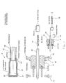
- Fig. 1
- einen Ausschnitt eines Fahrzeugs mit einem Ladekabel,
- Fig. 2
- Detailansichten des Ladekabels und
- Fig. 3
- einen Ausschnitt des Fahrzeugs in einer weiteren Ausgestaltung.
- In
Fig. 1 ist ein Fahrzeug 1 mit einem Elektroantrieb zu sehen, bei dem es sich insbesondere um ein Pedelec, ein E-Bike o. dgl. handelt. Das Fahrzeug 1 besitzt einen Rahmen 2 und einen am Rahmen 2 angeordneten Akku 3 (sieheFig. 3 ) zur Energieversorgung des Elektroantriebs. Selbstverständlich kann der Akku 3 auch im Rahmen 2 oder an sonstiger Stelle des Fahrzeugs 1 angeordnet sein, was jedoch nicht weiter gezeigt ist. Der Akku 3 ist mit der einen Seite 5 eines Ladekabels 4 elektrisch verbunden, derart dass eine Energieübertragung mittels des Ladekabels 4 von einer Ladestation 7 auf den Akku 3 zum Aufladen des Akkus 3 ermöglicht ist. - Das Ladekabel 4 ist ausziehbar und/oder einschiebbar im und/oder am Rahmen 2 angeordnet, und zwar in einem Rahmenrohr. Vorliegend handelt es sich um das Unterrohr des Rahmens 2. Selbstverständlich ist auch eine Anordnung des Ladekabels 4 im Oberrohr oder im Sattelrohr des Rahmens 2 möglich. Das Ladekabel 4 ist somit in der Art eines integrierten Ladekabels ausgestaltet.
- An der anderen Seite 6 des Ladekabels 4 ist ein Stecker 8 zur Aufnahme in einer Steckdose 9 an der Ladestation 7 angeordnet. Der Stecker 8 ist in der Steckdose 9 an der Ladestation 7 verriegelbar, so dass eine Diebstahlsicherung für das Fahrzeug 1 während des Ladevorgangs gegeben ist. Die Verriegelung des Steckers 8 in der Steckdose 9 kann mechanisch und/oder elektrisch, beispielsweise elektromotorisch, elektromagnetisch o. dgl., erfolgen.
- Wie man weiter anhand der
Fig. 3 sieht, kann der Akku 3 eine Steckdose 10 zur Aufnahme eines Steckers von einem separaten Ladekabel zur Ladestation 7 aufweisen. Dadurch ist wahlweise auch eine Energieübertragung von der Ladestation 7 mittels des separaten Ladekabels auf den Akku 3 zum Aufladen des Akkus 3 ermöglicht. Es ist eine mittels eines Schlosses 12 betätigbare Verriegelungseinrichtung 11 für die Steckdose 10 im Akku 3 vorgesehen, derart dass der in der Steckdose 10 eingesteckte Stecker des separaten Ladekabels mittels der Verriegelungseinrichtung 11 in der Steckdose 10 sperrbar und/oder freigebbar ist. Dann kann zur Diebstahlsicherung des Fahrzeugs 1 auch der Stecker 8 des integrierten Ladekabels 4, das um einen festen Gegenstand 13, beispielsweise einen Baum, einen Laternenpfahl o. dgl. geschlungen ist, verriegelbar in die Steckdose 10 am Akku 3 einsteckbar sein. Zur Unterstützung für die Diebstahlsicherung kann zusätzlich eine Durchstecköse 24 am Ladekabel 4 angeordnet sein. GemäßFig. 2 weist der Stecker 8 des Ladekabels 4 einen Hinterschnitt 25 auf. Die Verriegelungseinrichtung 11 umfasst einen nicht weiter gezeigten, bewegbaren Hebel, derart dass der Hebel zur Verriegelung in den Hinterschnitt 25 des in die Steckdose 10 eingesteckten Steckers 8 des integrierten Ladekabels 4 beziehungsweise des separaten Ladekabels eingreift. Selbstverständlich kann bei einem Verzicht auf die Aufladbarkeit mittels eines separaten Ladekabels die Steckdose 10 ohne elektrische Verbindung zum Akku 3 lediglich für die Diebstahlsicherung mittels des integrierten Ladekabels 4 vorgesehen sein. - Zwecks Ausziehbarkeit des integrierten Ladekabels 4 ist gemäß
Fig. 1 das integrierte Ladekabel 4 mittels eines geschützt im Rahmen 2 befindlichen Spiralkabels 14 über eine Elektronik 15 mit dem Akku 3 elektrisch verbunden. Wie weiter anhand vonFig. 2 zu erkennen ist, ist wenigstens ein Anschlag 16 im Rahmen 2 angeordnet zur Zusammenwirkung mit einem Gegenanschlag 18 am integrierten Ladekabel 4, derart dass die eingeschobene Position des Ladekabels 4 im Rahmen 2 fixiert ist. Wenigstes ein weiterer Anschlag 17 ist im Rahmen 2 angeordnet zur Zusammenwirkung mit dem Gegenanschlag 18 am integrierten Ladekabel 4, derart dass die Ausziehlänge des integrierten Ladekabels 4 begrenzt ist. Anstelle eines Spiralkabels kann auch eine federartige Schleife 19, die in der Art einer Zugentlastung wirkt, für das integrierte Ladekabel 4 vorgesehen sein. - Wie man weiter in
Fig. 2 sieht, umfasst das integrierte Ladekabel 4 den Stecker 8 sowie eine elektrische Leitung 20. Der Stecker 8 weist eine metallische Hülle 21 und/oder die Leitung 20 weist eine metallische Ummantelung 22 auf. Der Hinterschnitt 25 befindet sich an der metallischen Hülle 21. Die metallische Hülle 21 ist an der metallischen Ummantelung 22 mittels einer Crimp-Verbindung 23 befestigt. Die metallische Ummantelung 22 besteht aus einem Metallschlauch. Die metallische Hülle 21 kann aus einem Drehteil, einem Tiefziehteil, einem Gießteil o. dgl. bestehen. - Schließlich kann es sich noch anbieten, dass bei einer Manipulation am Ladekabel 4 ein Alarm am Fahrzeug 1 erzeugt wird. Dieser Alarm kann am Fahrzeug 1 akustisch, optisch o. dgl. ausgegebenen werden. Falls gewünscht kann vom Fahrzeug 1 in diesem Fall auch eine Meldung an ein Telefon, beispielsweise ein Mobiltelefon und/oder ein Smartphone, des berechtigten Benutzers übermittelt werden, die diesem den Diebstahlversuch für das Fahrzeug 1 anzeigt. Selbstverständlich kann in einem solchen Fall auch der Betrieb des Fahrzeugs 1 gesperrt werden.
- Die Erfindung ist nicht auf das beschriebene und dargestellte Ausführungsbeispiel beschränkt. Sie umfasst vielmehr auch alle fachmännischen Weiterbildungen im Rahmen der durch die Patentansprüche definierten Erfindung. So kann das erfindungsgemäße integrierte Ladekabel 4 nicht nur bei Pedelecs, E-Bikes o. dgl. sondern auch in sonstigen Elektrofahrzeugen, beispielsweise in LEV-Systemen (Light Electric Vehicle), eingesetzt werden.
-
- 1:
- Fahrzeug
- 2:
- Rahmen
- 3:
- Akku
- 4:
- (integriertes) Ladekabel
- 5,6:
- Seite (des Ladekabels)
- 7:
- Ladestation
- 8:
- Stecker
- 9:
- Steckdose (in Ladestation)
- 10:
- Steckdose (an Akku)
- 11:
- Verriegelungseinrichtung
- 12:
- Schloss
- 13:
- (fester) Gegenstand
- 14:
- Spiralkabel
- 15:
- Elektronik
- 16,17:
- Anschlag (im Rahmen)
- 18:
- Gegenanschlag (an Ladekabel)
- 19:
- (federartige) Schleife
- 20:
- (elektrische) Leitung
- 21:
- (metallische) Hülle
- 22:
- (metallische) Ummantelung
- 23:
- Crimp-Verbindung
- 24:
- Durchstecköse
- 25:
- Hinterschnitt
Claims (9)
- Fahrzeug, insbesondere Pedelec, E-Bike o. dgl., mit einem Rahmen (2) und mit einem insbesondere am Rahmen (2) angeordneten Akku (3), wobei der Akku (3) mit der einen Seite (5) eines Ladekabels (4) elektrisch verbunden ist, derart dass eine Energieübertragung mittels des Ladekabels (4) von einer Ladestation (7) auf den Akku (3) zum Aufladen des Akkus (3) ermöglicht ist, dadurch gekennzeichnet, dass das Ladekabel (4) ausziehbar und/oder einschiebbar im und/oder am Rahmen (2), insbesondere in einem Rahmenrohr des Rahmens (2), in der Art eines integrierten Ladekabels angeordnet ist.
- Fahrzeug nach Anspruch 1, dadurch gekennzeichnet, dass an der anderen Seite (6) des Ladekabels (4) ein Stecker (8) zur Aufnahme in einer Steckdose (9) an der Ladestation (7) angeordnet ist, und dass vorzugsweise der Stecker (8), insbesondere mechanisch und/oder elektrisch, verriegelbar in der Steckdose (9) an der Ladestation (7) ist.
- Fahrzeug nach Anspruch 1 oder 2, dadurch gekennzeichnet, dass der Akku (3) eine Steckdose (10), insbesondere zur Aufnahme eines Steckers von einem separaten Ladekabel zur Ladestation (7), aufweist, insbesondere derart dass eine Energieübertragung von der Ladestation (7) mittels des separaten Ladekabels auf den Akku (3) zum Aufladen des Akkus (3) ermöglicht ist, dass vorzugsweise eine Verriegelungseinrichtung (11) für die Steckdose (10) im Akku (3) vorgesehen ist, derart dass der in der Steckdose (10) eingesteckte Stecker des separaten Ladekabels mittels der Verriegelungseinrichtung (11) in der Steckdose (10) sperrbar und/oder freigebbar ist, und dass weiter vorzugsweise der Stecker (8) des integrierten Ladekabels (4) zur Diebstahlsicherung des Fahrzeugs (1) verriegelbar in die Steckdose (10) am Akku (3) einsteckbar ist.
- Fahrzeug nach Anspruch 1, 2 oder 3, dadurch gekennzeichnet, dass der Stecker (8) des Ladekabels (4) einen Hinterschnitt (25) aufweist, und dass vorzugsweise die Verriegelungseinrichtung (11) einen bewegbaren Hebel umfasst, derart dass der Hebel zur Verriegelung in den Hinterschnitt (25) des in die Steckdose (10) eingesteckten Steckers (8) des Ladekabels (4) eingreift.
- Fahrzeug nach einem der Ansprüche 1 bis 4, dadurch gekennzeichnet, dass das integrierte Ladekabel (4) mittels eines geschützt im Rahmen (2) befindlichen Spiralkabels (14) und/oder einer Zugentlastung mit dem Akku (3) elektrisch verbunden ist.
- Fahrzeug nach einem der Ansprüche 1 bis 5, dadurch gekennzeichnet, dass wenigstens ein Anschlag (16) im Rahmen (2) angeordnet ist zur Zusammenwirkung mit dem integrierten Ladekabel (4), derart dass die eingeschobene Position des Ladekabels (4) im Rahmen (2) fixiert ist, und dass vorzugsweise wenigstes ein weiterer Anschlag (17) im Rahmen (2) angeordnet ist zur Zusammenwirkung mit dem integrierten Ladekabel (4), derart dass die Ausziehlänge des integrierten Ladekabels (4) begrenzt ist.
- Fahrzeug nach einem der Ansprüche 1 bis 6, dadurch gekennzeichnet, dass bei einer Manipulation am Ladekabel (4) ein Alarm erzeugbar, eine Meldung an ein Telefon übermittelbar, der Betrieb des Fahrzeugs (1) sperrbar o. dgl. ist.
- Ladekabel mit einem Stecker (8) sowie einer elektrischen Leitung (20), insbesondere nach einem der vorhergehenden Ansprüche, dadurch gekennzeichnet, dass der Stecker (8) eine metallische Hülle (21) und/oder die Leitung (20) eine metallische Ummantelung (22) aufweist, dass vorzugsweise der Hinterschnitt (25) an der metallischen Hülle (21) befindlich ist, und dass weiter vorzugsweise die metallische Hülle (21) an der metallischen Ummantelung (22) mittels einer Crimp-Verbindung (23) befestigt ist.
- Ladekabel nach Anspruch 8, dadurch gekennzeichnet, dass die metallische Ummantelung (22) aus einem Metallschlauch besteht, und dass vorzugsweise die metallische Hülle (21) aus einem Drehteil, einem Tiefziehteil, einem Gießteil o. dgl. besteht.
Applications Claiming Priority (1)
| Application Number | Priority Date | Filing Date | Title |
|---|---|---|---|
| DE102014002741 | 2014-03-04 |
Publications (2)
| Publication Number | Publication Date |
|---|---|
| EP2915732A1 true EP2915732A1 (de) | 2015-09-09 |
| EP2915732B1 EP2915732B1 (de) | 2019-08-28 |
Family
ID=52633107
Family Applications (1)
| Application Number | Title | Priority Date | Filing Date |
|---|---|---|---|
| EP15157512.3A Active EP2915732B1 (de) | 2014-03-04 | 2015-03-04 | Elektrofahrzeug mit integriertem Ladekabel |
Country Status (2)
| Country | Link |
|---|---|
| EP (1) | EP2915732B1 (de) |
| DE (1) | DE102015002487A1 (de) |
Cited By (3)
| Publication number | Priority date | Publication date | Assignee | Title |
|---|---|---|---|---|
| CN114161966A (zh) * | 2021-12-29 | 2022-03-11 | 东莞泰合复合材料有限公司 | 碳纤维自行车充电接口的加工方法 |
| EP3927606A4 (de) * | 2019-02-19 | 2022-11-23 | Metro Mobility, LLC | Bordfahrzeugschloss |
| US11951853B2 (en) | 2018-12-11 | 2024-04-09 | Metro Mobility, Llc | Electric vehicle fastening and charging system with wireless control |
Families Citing this family (3)
| Publication number | Priority date | Publication date | Assignee | Title |
|---|---|---|---|---|
| AT518901B1 (de) * | 2016-08-31 | 2018-02-15 | SCHITTER Volkmar | Lade- und absperrvorrichtung für elektrofahrzeuge |
| DE102018005536A1 (de) * | 2017-07-21 | 2019-01-24 | Marquardt Verwaltungs-Gmbh | Fahrzeug |
| DE102018116408B4 (de) * | 2018-07-06 | 2022-08-25 | Pierer E-Bikes Deutschland Gmbh | Fahrradrahmen mit einer Antriebsaufnahme |
Citations (6)
| Publication number | Priority date | Publication date | Assignee | Title |
|---|---|---|---|---|
| EP1215111A1 (de) * | 1999-03-01 | 2002-06-19 | TOKYO R & D Co., Ltd. | Elektrisches fahrzeug |
| US6505846B1 (en) * | 2000-09-20 | 2003-01-14 | E Z Lock, Llc | Bicycle cable locking system |
| WO2008157443A2 (en) * | 2007-06-13 | 2008-12-24 | Intrago Corporation | Shared vehicle management system |
| DE202009011119U1 (de) * | 2009-08-14 | 2009-11-26 | Schaeffler Kg | Fahrrad mit Nachrüstsatz zu dessen elektrischem Betrieb |
| US20120197470A1 (en) * | 2011-02-02 | 2012-08-02 | Honda Motor Co., Ltd. | Motorcycle |
| WO2012107448A1 (de) * | 2011-02-07 | 2012-08-16 | Energybus E.V. | Modulares fahrzeugsystem, elektrofahrzeug und modul zur verbindung mit einem elektrofahrzeug |
Family Cites Families (3)
| Publication number | Priority date | Publication date | Assignee | Title |
|---|---|---|---|---|
| WO2002004280A1 (en) * | 2000-07-10 | 2002-01-17 | Frank Anthony Ierfone | Securing bicycles and the like from theft |
| DE20104786U1 (de) * | 2001-03-20 | 2001-06-28 | Scholle Markus | Fahrradschloß |
| CN202917607U (zh) * | 2012-11-20 | 2013-05-01 | 赵任仁 | 带有自动收线充电装置的电池 |
-
2015
- 2015-02-27 DE DE102015002487.6A patent/DE102015002487A1/de not_active Withdrawn
- 2015-03-04 EP EP15157512.3A patent/EP2915732B1/de active Active
Patent Citations (6)
| Publication number | Priority date | Publication date | Assignee | Title |
|---|---|---|---|---|
| EP1215111A1 (de) * | 1999-03-01 | 2002-06-19 | TOKYO R & D Co., Ltd. | Elektrisches fahrzeug |
| US6505846B1 (en) * | 2000-09-20 | 2003-01-14 | E Z Lock, Llc | Bicycle cable locking system |
| WO2008157443A2 (en) * | 2007-06-13 | 2008-12-24 | Intrago Corporation | Shared vehicle management system |
| DE202009011119U1 (de) * | 2009-08-14 | 2009-11-26 | Schaeffler Kg | Fahrrad mit Nachrüstsatz zu dessen elektrischem Betrieb |
| US20120197470A1 (en) * | 2011-02-02 | 2012-08-02 | Honda Motor Co., Ltd. | Motorcycle |
| WO2012107448A1 (de) * | 2011-02-07 | 2012-08-16 | Energybus E.V. | Modulares fahrzeugsystem, elektrofahrzeug und modul zur verbindung mit einem elektrofahrzeug |
Cited By (4)
| Publication number | Priority date | Publication date | Assignee | Title |
|---|---|---|---|---|
| US11951853B2 (en) | 2018-12-11 | 2024-04-09 | Metro Mobility, Llc | Electric vehicle fastening and charging system with wireless control |
| EP3927606A4 (de) * | 2019-02-19 | 2022-11-23 | Metro Mobility, LLC | Bordfahrzeugschloss |
| CN114161966A (zh) * | 2021-12-29 | 2022-03-11 | 东莞泰合复合材料有限公司 | 碳纤维自行车充电接口的加工方法 |
| CN114161966B (zh) * | 2021-12-29 | 2024-03-12 | 东莞泰合复合材料有限公司 | 碳纤维自行车充电接口的加工方法 |
Also Published As
| Publication number | Publication date |
|---|---|
| DE102015002487A1 (de) | 2015-09-10 |
| EP2915732B1 (de) | 2019-08-28 |
Similar Documents
| Publication | Publication Date | Title |
|---|---|---|
| EP2915732B1 (de) | Elektrofahrzeug mit integriertem Ladekabel | |
| DE102010017458B4 (de) | Elektrostecker | |
| DE102018006690A1 (de) | Fahrzeug | |
| EP2566746B1 (de) | Antriebseinheit mit sperrmechanismus und verfahren zur sperrung einer antriebseinheit | |
| DE102009010852B4 (de) | Stützstruktur einer Fahrzeugstromleitung | |
| DE102010044138A1 (de) | Ladestecker mit Verriegelungserkennung | |
| DE102010041323A1 (de) | Ladeeinrichtung für ein Elektrofahrzeug nebst Verfahren | |
| EP3507131B1 (de) | Lade- und absperrvorrichtung für elektrofahrzeuge | |
| DE102013204904A1 (de) | Ladekabelschloss für ein Elektrofahrzeug | |
| DE102010041314B4 (de) | Ladeeinrichtung für ein Elektrofahrzeug nebst Verfahren | |
| DE102010038568B4 (de) | Elektrische Steckverbindung | |
| DE102011007763A1 (de) | Adapterkabel zur Wandlung eines an einem Fahrzeugladekabel vorgesehenen Anschlusses eines ersten Typs in einen Anschluss zweiten Typs | |
| EP2627531A2 (de) | Vorrichtung zum verbinden eines fahrzeugs mit einer steckdose | |
| DE102015002486A1 (de) | Fahrzeug | |
| DE4308296C1 (de) | Diebstahlgesicherter Roller mit Elektroantrieb | |
| EP3820731B1 (de) | Ladevorrichtung zum laden einer batterie eines elektrisch betreibbaren kraftfahrzeugs | |
| EP2955046B1 (de) | Elektrisch betreibbares fahrzeug, insbesondere elektrofahrrad, mit verbesserter batterieanordnung | |
| DE102011011461A1 (de) | Ladekabelverriegelungseinrichtung für ein Fahrzeug | |
| DE102017121568A1 (de) | Träger für ein Kraftfahrzeug | |
| EP3431373A1 (de) | Fahrzeug | |
| DE10043023A1 (de) | Sicherungsvorrichtung zum Schutz des Aufhebens einer elektrischen Verbindung durch einen Nichtberechtigten | |
| DE102012025083A1 (de) | Ladeeinrichtung für ein batteriebetriebenes Elektrofahrrad im öffentlichen Raum sowie mobiles Lademittel hierfür | |
| DE102021120892A1 (de) | Verfahren zum Auslösen einer Alarmfunktion bei unsachgemäßem Gebrauch eines Ladekabels, Steuereinrichtung und Kraftfahrzeug | |
| DE102020003961A1 (de) | Ladekabel zum Verbinden eines elektrisch betriebenen Fahrzeugs mit einer elektrischen Ladestation | |
| DE102010042632A1 (de) | Elektrische Steckverbindung |
Legal Events
| Date | Code | Title | Description |
|---|---|---|---|
| PUAI | Public reference made under article 153(3) epc to a published international application that has entered the european phase |
Free format text: ORIGINAL CODE: 0009012 |
|
| AK | Designated contracting states |
Kind code of ref document: A1 Designated state(s): AL AT BE BG CH CY CZ DE DK EE ES FI FR GB GR HR HU IE IS IT LI LT LU LV MC MK MT NL NO PL PT RO RS SE SI SK SM TR |
|
| AX | Request for extension of the european patent |
Extension state: BA ME |
|
| 17P | Request for examination filed |
Effective date: 20160309 |
|
| RBV | Designated contracting states (corrected) |
Designated state(s): AL AT BE BG CH CY CZ DE DK EE ES FI FR GB GR HR HU IE IS IT LI LT LU LV MC MK MT NL NO PL PT RO RS SE SI SK SM TR |
|
| 17Q | First examination report despatched |
Effective date: 20160705 |
|
| STAA | Information on the status of an ep patent application or granted ep patent |
Free format text: STATUS: EXAMINATION IS IN PROGRESS |
|
| GRAP | Despatch of communication of intention to grant a patent |
Free format text: ORIGINAL CODE: EPIDOSNIGR1 |
|
| STAA | Information on the status of an ep patent application or granted ep patent |
Free format text: STATUS: GRANT OF PATENT IS INTENDED |
|
| INTG | Intention to grant announced |
Effective date: 20190327 |
|
| GRAS | Grant fee paid |
Free format text: ORIGINAL CODE: EPIDOSNIGR3 |
|
| GRAA | (expected) grant |
Free format text: ORIGINAL CODE: 0009210 |
|
| STAA | Information on the status of an ep patent application or granted ep patent |
Free format text: STATUS: THE PATENT HAS BEEN GRANTED |
|
| AK | Designated contracting states |
Kind code of ref document: B1 Designated state(s): AL AT BE BG CH CY CZ DE DK EE ES FI FR GB GR HR HU IE IS IT LI LT LU LV MC MK MT NL NO PL PT RO RS SE SI SK SM TR |
|
| REG | Reference to a national code |
Ref country code: GB Ref legal event code: FG4D Free format text: NOT ENGLISH |
|
| REG | Reference to a national code |
Ref country code: CH Ref legal event code: EP |
|
| REG | Reference to a national code |
Ref country code: AT Ref legal event code: REF Ref document number: 1172060 Country of ref document: AT Kind code of ref document: T Effective date: 20190915 |
|
| REG | Reference to a national code |
Ref country code: IE Ref legal event code: FG4D Free format text: LANGUAGE OF EP DOCUMENT: GERMAN |
|
| REG | Reference to a national code |
Ref country code: DE Ref legal event code: R096 Ref document number: 502015010112 Country of ref document: DE |
|
| REG | Reference to a national code |
Ref country code: NL Ref legal event code: MP Effective date: 20190828 |
|
| REG | Reference to a national code |
Ref country code: LT Ref legal event code: MG4D |
|
| PG25 | Lapsed in a contracting state [announced via postgrant information from national office to epo] |
Ref country code: PT Free format text: LAPSE BECAUSE OF FAILURE TO SUBMIT A TRANSLATION OF THE DESCRIPTION OR TO PAY THE FEE WITHIN THE PRESCRIBED TIME-LIMIT Effective date: 20191230 Ref country code: LT Free format text: LAPSE BECAUSE OF FAILURE TO SUBMIT A TRANSLATION OF THE DESCRIPTION OR TO PAY THE FEE WITHIN THE PRESCRIBED TIME-LIMIT Effective date: 20190828 Ref country code: HR Free format text: LAPSE BECAUSE OF FAILURE TO SUBMIT A TRANSLATION OF THE DESCRIPTION OR TO PAY THE FEE WITHIN THE PRESCRIBED TIME-LIMIT Effective date: 20190828 Ref country code: NO Free format text: LAPSE BECAUSE OF FAILURE TO SUBMIT A TRANSLATION OF THE DESCRIPTION OR TO PAY THE FEE WITHIN THE PRESCRIBED TIME-LIMIT Effective date: 20191128 Ref country code: SE Free format text: LAPSE BECAUSE OF FAILURE TO SUBMIT A TRANSLATION OF THE DESCRIPTION OR TO PAY THE FEE WITHIN THE PRESCRIBED TIME-LIMIT Effective date: 20190828 Ref country code: FI Free format text: LAPSE BECAUSE OF FAILURE TO SUBMIT A TRANSLATION OF THE DESCRIPTION OR TO PAY THE FEE WITHIN THE PRESCRIBED TIME-LIMIT Effective date: 20190828 Ref country code: BG Free format text: LAPSE BECAUSE OF FAILURE TO SUBMIT A TRANSLATION OF THE DESCRIPTION OR TO PAY THE FEE WITHIN THE PRESCRIBED TIME-LIMIT Effective date: 20191128 Ref country code: NL Free format text: LAPSE BECAUSE OF FAILURE TO SUBMIT A TRANSLATION OF THE DESCRIPTION OR TO PAY THE FEE WITHIN THE PRESCRIBED TIME-LIMIT Effective date: 20190828 |
|
| PG25 | Lapsed in a contracting state [announced via postgrant information from national office to epo] |
Ref country code: IS Free format text: LAPSE BECAUSE OF FAILURE TO SUBMIT A TRANSLATION OF THE DESCRIPTION OR TO PAY THE FEE WITHIN THE PRESCRIBED TIME-LIMIT Effective date: 20191228 Ref country code: RS Free format text: LAPSE BECAUSE OF FAILURE TO SUBMIT A TRANSLATION OF THE DESCRIPTION OR TO PAY THE FEE WITHIN THE PRESCRIBED TIME-LIMIT Effective date: 20190828 Ref country code: AL Free format text: LAPSE BECAUSE OF FAILURE TO SUBMIT A TRANSLATION OF THE DESCRIPTION OR TO PAY THE FEE WITHIN THE PRESCRIBED TIME-LIMIT Effective date: 20190828 Ref country code: LV Free format text: LAPSE BECAUSE OF FAILURE TO SUBMIT A TRANSLATION OF THE DESCRIPTION OR TO PAY THE FEE WITHIN THE PRESCRIBED TIME-LIMIT Effective date: 20190828 Ref country code: ES Free format text: LAPSE BECAUSE OF FAILURE TO SUBMIT A TRANSLATION OF THE DESCRIPTION OR TO PAY THE FEE WITHIN THE PRESCRIBED TIME-LIMIT Effective date: 20190828 Ref country code: GR Free format text: LAPSE BECAUSE OF FAILURE TO SUBMIT A TRANSLATION OF THE DESCRIPTION OR TO PAY THE FEE WITHIN THE PRESCRIBED TIME-LIMIT Effective date: 20191129 |
|
| PG25 | Lapsed in a contracting state [announced via postgrant information from national office to epo] |
Ref country code: TR Free format text: LAPSE BECAUSE OF FAILURE TO SUBMIT A TRANSLATION OF THE DESCRIPTION OR TO PAY THE FEE WITHIN THE PRESCRIBED TIME-LIMIT Effective date: 20190828 |
|
| PG25 | Lapsed in a contracting state [announced via postgrant information from national office to epo] |
Ref country code: DK Free format text: LAPSE BECAUSE OF FAILURE TO SUBMIT A TRANSLATION OF THE DESCRIPTION OR TO PAY THE FEE WITHIN THE PRESCRIBED TIME-LIMIT Effective date: 20190828 Ref country code: PL Free format text: LAPSE BECAUSE OF FAILURE TO SUBMIT A TRANSLATION OF THE DESCRIPTION OR TO PAY THE FEE WITHIN THE PRESCRIBED TIME-LIMIT Effective date: 20190828 Ref country code: RO Free format text: LAPSE BECAUSE OF FAILURE TO SUBMIT A TRANSLATION OF THE DESCRIPTION OR TO PAY THE FEE WITHIN THE PRESCRIBED TIME-LIMIT Effective date: 20190828 Ref country code: EE Free format text: LAPSE BECAUSE OF FAILURE TO SUBMIT A TRANSLATION OF THE DESCRIPTION OR TO PAY THE FEE WITHIN THE PRESCRIBED TIME-LIMIT Effective date: 20190828 Ref country code: IT Free format text: LAPSE BECAUSE OF FAILURE TO SUBMIT A TRANSLATION OF THE DESCRIPTION OR TO PAY THE FEE WITHIN THE PRESCRIBED TIME-LIMIT Effective date: 20190828 |
|
| PG25 | Lapsed in a contracting state [announced via postgrant information from national office to epo] |
Ref country code: SM Free format text: LAPSE BECAUSE OF FAILURE TO SUBMIT A TRANSLATION OF THE DESCRIPTION OR TO PAY THE FEE WITHIN THE PRESCRIBED TIME-LIMIT Effective date: 20190828 Ref country code: CZ Free format text: LAPSE BECAUSE OF FAILURE TO SUBMIT A TRANSLATION OF THE DESCRIPTION OR TO PAY THE FEE WITHIN THE PRESCRIBED TIME-LIMIT Effective date: 20190828 Ref country code: SK Free format text: LAPSE BECAUSE OF FAILURE TO SUBMIT A TRANSLATION OF THE DESCRIPTION OR TO PAY THE FEE WITHIN THE PRESCRIBED TIME-LIMIT Effective date: 20190828 Ref country code: IS Free format text: LAPSE BECAUSE OF FAILURE TO SUBMIT A TRANSLATION OF THE DESCRIPTION OR TO PAY THE FEE WITHIN THE PRESCRIBED TIME-LIMIT Effective date: 20200224 |
|
| REG | Reference to a national code |
Ref country code: DE Ref legal event code: R097 Ref document number: 502015010112 Country of ref document: DE |
|
| PLBE | No opposition filed within time limit |
Free format text: ORIGINAL CODE: 0009261 |
|
| STAA | Information on the status of an ep patent application or granted ep patent |
Free format text: STATUS: NO OPPOSITION FILED WITHIN TIME LIMIT |
|
| PG2D | Information on lapse in contracting state deleted |
Ref country code: IS |
|
| 26N | No opposition filed |
Effective date: 20200603 |
|
| PG25 | Lapsed in a contracting state [announced via postgrant information from national office to epo] |
Ref country code: SI Free format text: LAPSE BECAUSE OF FAILURE TO SUBMIT A TRANSLATION OF THE DESCRIPTION OR TO PAY THE FEE WITHIN THE PRESCRIBED TIME-LIMIT Effective date: 20190828 |
|
| REG | Reference to a national code |
Ref country code: DE Ref legal event code: R082 Ref document number: 502015010112 Country of ref document: DE Representative=s name: JOSTARNDT PATENTANWALTS-AG, DE |
|
| PG25 | Lapsed in a contracting state [announced via postgrant information from national office to epo] |
Ref country code: MC Free format text: LAPSE BECAUSE OF FAILURE TO SUBMIT A TRANSLATION OF THE DESCRIPTION OR TO PAY THE FEE WITHIN THE PRESCRIBED TIME-LIMIT Effective date: 20190828 |
|
| REG | Reference to a national code |
Ref country code: CH Ref legal event code: PL |
|
| REG | Reference to a national code |
Ref country code: BE Ref legal event code: MM Effective date: 20200331 |
|
| PG25 | Lapsed in a contracting state [announced via postgrant information from national office to epo] |
Ref country code: LU Free format text: LAPSE BECAUSE OF NON-PAYMENT OF DUE FEES Effective date: 20200304 |
|
| PG25 | Lapsed in a contracting state [announced via postgrant information from national office to epo] |
Ref country code: IE Free format text: LAPSE BECAUSE OF NON-PAYMENT OF DUE FEES Effective date: 20200304 Ref country code: FR Free format text: LAPSE BECAUSE OF NON-PAYMENT OF DUE FEES Effective date: 20200331 Ref country code: LI Free format text: LAPSE BECAUSE OF NON-PAYMENT OF DUE FEES Effective date: 20200331 Ref country code: CH Free format text: LAPSE BECAUSE OF NON-PAYMENT OF DUE FEES Effective date: 20200331 |
|
| PG25 | Lapsed in a contracting state [announced via postgrant information from national office to epo] |
Ref country code: BE Free format text: LAPSE BECAUSE OF NON-PAYMENT OF DUE FEES Effective date: 20200331 |
|
| GBPC | Gb: european patent ceased through non-payment of renewal fee |
Effective date: 20200304 |
|
| PG25 | Lapsed in a contracting state [announced via postgrant information from national office to epo] |
Ref country code: GB Free format text: LAPSE BECAUSE OF NON-PAYMENT OF DUE FEES Effective date: 20200304 |
|
| REG | Reference to a national code |
Ref country code: AT Ref legal event code: MM01 Ref document number: 1172060 Country of ref document: AT Kind code of ref document: T Effective date: 20200304 |
|
| PGFP | Annual fee paid to national office [announced via postgrant information from national office to epo] |
Ref country code: DE Payment date: 20210331 Year of fee payment: 7 |
|
| PG25 | Lapsed in a contracting state [announced via postgrant information from national office to epo] |
Ref country code: AT Free format text: LAPSE BECAUSE OF NON-PAYMENT OF DUE FEES Effective date: 20200304 |
|
| PG25 | Lapsed in a contracting state [announced via postgrant information from national office to epo] |
Ref country code: MT Free format text: LAPSE BECAUSE OF FAILURE TO SUBMIT A TRANSLATION OF THE DESCRIPTION OR TO PAY THE FEE WITHIN THE PRESCRIBED TIME-LIMIT Effective date: 20190828 Ref country code: CY Free format text: LAPSE BECAUSE OF FAILURE TO SUBMIT A TRANSLATION OF THE DESCRIPTION OR TO PAY THE FEE WITHIN THE PRESCRIBED TIME-LIMIT Effective date: 20190828 |
|
| PG25 | Lapsed in a contracting state [announced via postgrant information from national office to epo] |
Ref country code: MK Free format text: LAPSE BECAUSE OF FAILURE TO SUBMIT A TRANSLATION OF THE DESCRIPTION OR TO PAY THE FEE WITHIN THE PRESCRIBED TIME-LIMIT Effective date: 20190828 |
|
| REG | Reference to a national code |
Ref country code: DE Ref legal event code: R119 Ref document number: 502015010112 Country of ref document: DE |
|
| PG25 | Lapsed in a contracting state [announced via postgrant information from national office to epo] |
Ref country code: DE Free format text: LAPSE BECAUSE OF NON-PAYMENT OF DUE FEES Effective date: 20221001 |