EP2915671A1 - Inkjet printing device - Google Patents
Inkjet printing device Download PDFInfo
- Publication number
- EP2915671A1 EP2915671A1 EP13850916.1A EP13850916A EP2915671A1 EP 2915671 A1 EP2915671 A1 EP 2915671A1 EP 13850916 A EP13850916 A EP 13850916A EP 2915671 A1 EP2915671 A1 EP 2915671A1
- Authority
- EP
- European Patent Office
- Prior art keywords
- blade
- cleaning liquid
- ink jet
- ink
- distal end
- Prior art date
- Legal status (The legal status is an assumption and is not a legal conclusion. Google has not performed a legal analysis and makes no representation as to the accuracy of the status listed.)
- Withdrawn
Links
- 238000007641 inkjet printing Methods 0.000 title description 2
- 238000004140 cleaning Methods 0.000 claims abstract description 215
- 239000007788 liquid Substances 0.000 claims abstract description 168
- 238000010586 diagram Methods 0.000 description 35
- 238000007599 discharging Methods 0.000 description 23
- 230000001464 adherent effect Effects 0.000 description 19
- 230000000694 effects Effects 0.000 description 15
- 238000000034 method Methods 0.000 description 11
- 238000007639 printing Methods 0.000 description 7
- 239000000463 material Substances 0.000 description 6
- 229920002943 EPDM rubber Polymers 0.000 description 2
- 239000004743 Polypropylene Substances 0.000 description 2
- 230000002378 acidificating effect Effects 0.000 description 2
- 238000001514 detection method Methods 0.000 description 2
- 229920001971 elastomer Polymers 0.000 description 2
- 239000004816 latex Substances 0.000 description 2
- 229920000126 latex Polymers 0.000 description 2
- 238000012423 maintenance Methods 0.000 description 2
- -1 polypropylene Polymers 0.000 description 2
- 229920001155 polypropylene Polymers 0.000 description 2
- 239000011347 resin Substances 0.000 description 2
- 229920005989 resin Polymers 0.000 description 2
- 239000002699 waste material Substances 0.000 description 2
- BZHJMEDXRYGGRV-UHFFFAOYSA-N Vinyl chloride Chemical compound ClC=C BZHJMEDXRYGGRV-UHFFFAOYSA-N 0.000 description 1
- 239000003513 alkali Substances 0.000 description 1
- 150000001732 carboxylic acid derivatives Chemical class 0.000 description 1
- 230000000593 degrading effect Effects 0.000 description 1
- 230000005284 excitation Effects 0.000 description 1
- 239000004744 fabric Substances 0.000 description 1
- 238000010438 heat treatment Methods 0.000 description 1
- 239000000123 paper Substances 0.000 description 1
- 230000002093 peripheral effect Effects 0.000 description 1
- 229920000728 polyester Polymers 0.000 description 1
- 230000000717 retained effect Effects 0.000 description 1
- 230000008961 swelling Effects 0.000 description 1
- 230000001960 triggered effect Effects 0.000 description 1
- 238000005406 washing Methods 0.000 description 1
- 230000003245 working effect Effects 0.000 description 1
Images


Classifications
-
- B—PERFORMING OPERATIONS; TRANSPORTING
- B41—PRINTING; LINING MACHINES; TYPEWRITERS; STAMPS
- B41J—TYPEWRITERS; SELECTIVE PRINTING MECHANISMS, i.e. MECHANISMS PRINTING OTHERWISE THAN FROM A FORME; CORRECTION OF TYPOGRAPHICAL ERRORS
- B41J2/00—Typewriters or selective printing mechanisms characterised by the printing or marking process for which they are designed
- B41J2/005—Typewriters or selective printing mechanisms characterised by the printing or marking process for which they are designed characterised by bringing liquid or particles selectively into contact with a printing material
- B41J2/01—Ink jet
- B41J2/135—Nozzles
- B41J2/165—Prevention or detection of nozzle clogging, e.g. cleaning, capping or moistening for nozzles
- B41J2/16517—Cleaning of print head nozzles
- B41J2/16535—Cleaning of print head nozzles using wiping constructions
-
- B—PERFORMING OPERATIONS; TRANSPORTING
- B41—PRINTING; LINING MACHINES; TYPEWRITERS; STAMPS
- B41J—TYPEWRITERS; SELECTIVE PRINTING MECHANISMS, i.e. MECHANISMS PRINTING OTHERWISE THAN FROM A FORME; CORRECTION OF TYPOGRAPHICAL ERRORS
- B41J2/00—Typewriters or selective printing mechanisms characterised by the printing or marking process for which they are designed
- B41J2/005—Typewriters or selective printing mechanisms characterised by the printing or marking process for which they are designed characterised by bringing liquid or particles selectively into contact with a printing material
- B41J2/01—Ink jet
- B41J2/135—Nozzles
- B41J2/165—Prevention or detection of nozzle clogging, e.g. cleaning, capping or moistening for nozzles
- B41J2/16517—Cleaning of print head nozzles
- B41J2/16535—Cleaning of print head nozzles using wiping constructions
- B41J2/16541—Means to remove deposits from wipers or scrapers
-
- B—PERFORMING OPERATIONS; TRANSPORTING
- B41—PRINTING; LINING MACHINES; TYPEWRITERS; STAMPS
- B41J—TYPEWRITERS; SELECTIVE PRINTING MECHANISMS, i.e. MECHANISMS PRINTING OTHERWISE THAN FROM A FORME; CORRECTION OF TYPOGRAPHICAL ERRORS
- B41J2/00—Typewriters or selective printing mechanisms characterised by the printing or marking process for which they are designed
- B41J2/005—Typewriters or selective printing mechanisms characterised by the printing or marking process for which they are designed characterised by bringing liquid or particles selectively into contact with a printing material
- B41J2/01—Ink jet
- B41J2/135—Nozzles
- B41J2/165—Prevention or detection of nozzle clogging, e.g. cleaning, capping or moistening for nozzles
- B41J2/16517—Cleaning of print head nozzles
- B41J2/16535—Cleaning of print head nozzles using wiping constructions
- B41J2/16538—Cleaning of print head nozzles using wiping constructions with brushes or wiper blades perpendicular to the nozzle plate
-
- B—PERFORMING OPERATIONS; TRANSPORTING
- B41—PRINTING; LINING MACHINES; TYPEWRITERS; STAMPS
- B41J—TYPEWRITERS; SELECTIVE PRINTING MECHANISMS, i.e. MECHANISMS PRINTING OTHERWISE THAN FROM A FORME; CORRECTION OF TYPOGRAPHICAL ERRORS
- B41J2/00—Typewriters or selective printing mechanisms characterised by the printing or marking process for which they are designed
- B41J2/005—Typewriters or selective printing mechanisms characterised by the printing or marking process for which they are designed characterised by bringing liquid or particles selectively into contact with a printing material
- B41J2/01—Ink jet
- B41J2/135—Nozzles
- B41J2/165—Prevention or detection of nozzle clogging, e.g. cleaning, capping or moistening for nozzles
- B41J2/16517—Cleaning of print head nozzles
- B41J2/16552—Cleaning of print head nozzles using cleaning fluids
-
- B—PERFORMING OPERATIONS; TRANSPORTING
- B41—PRINTING; LINING MACHINES; TYPEWRITERS; STAMPS
- B41J—TYPEWRITERS; SELECTIVE PRINTING MECHANISMS, i.e. MECHANISMS PRINTING OTHERWISE THAN FROM A FORME; CORRECTION OF TYPOGRAPHICAL ERRORS
- B41J2/00—Typewriters or selective printing mechanisms characterised by the printing or marking process for which they are designed
- B41J2/005—Typewriters or selective printing mechanisms characterised by the printing or marking process for which they are designed characterised by bringing liquid or particles selectively into contact with a printing material
- B41J2/01—Ink jet
- B41J2/135—Nozzles
- B41J2/165—Prevention or detection of nozzle clogging, e.g. cleaning, capping or moistening for nozzles
- B41J2/16517—Cleaning of print head nozzles
- B41J2/16552—Cleaning of print head nozzles using cleaning fluids
- B41J2002/16558—Using cleaning liquid for wet wiping
Definitions
- the present invention relates to an ink jet recording device and more specifically to an ink jet recording device that performs recording by discharging liquid onto a medium from an ink jet head mounted on a carriage which scans over the medium.
- an ink jet recording device when a print process is performed, discharged ink may gradually adhere to a nozzle surface of an ink jet head, and further, an ink droplet may be formed by the adherent ink merging with each other. Moreover, such an ink droplet gradually hardens, and in some cases may become viscous ink, for example in a gel form.
- a problem of print quality degrading may occur by the ink droplet dripping onto the recording medium, or by causing nozzle clogging.
- Patent Document 1 a technique that performs cleaning by wiping the nozzle surface of the ink jet head by a blade and the like formed of rubber material and the like has been known (for example, see Patent Document 1).
- Patent Document 1 JP 2005-014560 A
- the present invention has been made in view of the above problem, and an object thereof is to provide an ink jet recording device that can clean a blade of a wiper to which ink is adherent, whereby nozzle clogging in an ink jet head and ink color mixing therein are prevented to enable recording with high image quality.
- the problem may be solved by a solution as disclosed below.
- An ink jet recording device disclosed herein is characteristic in including a wiping unit that wipes off ink by sliding a blade on a nozzle surface of an ink jet head; and a cleaning unit that performs cleaning by pouring cleaning liquid on the blade.
- an ink jet recording device disclosed herein is characteristic in being an ink jet recording device in which liquid is supplied to an ink jet head mounted on a carriage that moves reciprocatingly in a horizontal scanning direction and the liquid is discharged from a nozzle of the ink jet head onto an opposing recording medium while the carriage is moving reciprocatingly in the horizontal scanning direction, the ink jet recording device including: a wiping unit including a blade that wipes off ink on a nozzle surface of the ink jet head by sliding its distal end portion on the nozzle surface from a lower side; and a cleaning unit including an outflow portion that allows cleaning liquid to flow out to a distal end portion side of the blade.
- the ink jet recording device since the nozzle surface of the ink jet head can be wiped by the blade of the wiping unit, the ink adherent to the nozzle surface can be removed. Moreover, the blade that has performed wiping can be cleaned by the cleaning unit, and the ink adherent to the blade can be removed; thus, the nozzle clogging and ink color mixing in the ink jet head can be prevented even in cases where wiping is performed continuously.
- the cleaning unit is preferably arranged at one end portion in the horizontal scanning direction, at a standby position for the ink jet head to stand by.
- the cleaning unit preferably allows the cleaning liquid to flow out to the distal end portion side of the blade in a state where the ink jet head has moved to the standby position.
- wiping of the nozzle surface and cleaning of the blade of the wiping unit can be performed by using the standby time of the ink jet head. Further, in view of a risk that an undesirable influence may occur in a print process if wiping and cleaning are performed during the print process, such an undesirable influence can be prevented.
- the ink jet recording device further includes a storage portion that stores the cleaning liquid; a flowing member having one end joined to the storage portion, including the outflow portion at the other end, and configured to allow the cleaning liquid to flow through an inside thereof; and a controlling member that controls an outflow of the cleaning liquid from the outflow portion and stoppage thereof.
- the cleaning liquid can be supplied from the storage portion provided in the ink jet recording device to perform cleaning of the blade of the wiping unit.
- the cleaning unit preferably includes a cleaning liquid guiding member between a distal end portion of the blade and the outflow portion, the cleaning liquid guiding member configured to expand a pouring region of the cleaning liquid and perform positioning of a pouring position. According to this, it becomes possible to pour the cleaning liquid over a wider region in a longitudinal direction of the blade with respect to a plate surface of the laterally elongate blade. Moreover, a pouring position, that is, a position where the cleaning liquid flows down can be set easily and highly accurately.
- the cleaning liquid guiding member has its distal end portion opposed to the distal end portion of the blade with respect to the blade at a predetermined position, and is arranged at a position that splits a flow of the cleaning liquid to both front and back surface sides of the blade. According to this, pouring can be performed on both front and back surfaces of the blade just by discharging the cleaning liquid, and the adherent ink can be washed off. Thus, a complicated mechanism for changing a discharging direction of the cleaning liquid to both surface sides of the blade does not need to be provided, whereby a device configuration can be simplified, and device cost reduction can be achieved.
- the cleaning liquid guiding member includes a straight portion of which distal end portion is formed straight
- the blade includes a straight portion of which distal end portion is formed straight
- the straight portion of the cleaning liquid guiding member and the straight portion of the blade are arranged to be opposed and parallel to each other
- the cleaning liquid guiding member has its distal end portion formed with a width by which the cleaning liquid flowed out from the outflow portion spreads over substantially an entire region in a width direction of the blade.
- the cleaning liquid guiding member includes a straight portion of which distal end portion is formed straight
- the blade includes a straight portion of which distal end portion is formed straight
- the straight portion of the cleaning liquid guiding member and the straight portion of the blade are arranged to be opposed and parallel to each other, and the distal end portions of the cleaning liquid guiding member and the blade are arranged at an interval by which the cleaning liquid flowed out from the outflow portion spreads over substantially an entire region in a width direction of the blade.
- the cleaning liquid guiding member is preferably supported by a supporting member by which the wiping unit is supported. According to this, by the cleaning liquid guiding member and the wiping unit (especially the blade) being supported by the same supporting member, positional accuracy of arrangements of both the cleaning liquid guiding member and the blade can be improved.
- the wiping unit preferably includes step portions on both surface sides of the blade at positions that are lower than a distal end portion of the blade by a predetermined length. According to this, the cleaning liquid that has been poured onto the blade flows in left and right directions on the step portions and reaches the wider region in the longitudinal direction, whereby an effect that the surface of the blade is cleaned over a wide region can be achieved. Moreover, since flows of the cleaning liquid from a center toward both the left direction and the right direction are generated, the cleaning effect can further be increased.
- the wiping unit and the cleaning unit are provided to clean the blade of the wiper to which the ink has adhered, whereby nozzle clogging in the ink jet head and ink color mixing therein can be prevented, and recording with high image quality becomes possible.
- FIG. 1 shows a schematic diagram (plan diagram) of an ink jet recording device 1 according to this embodiment.
- FIG. 2 shows a schematic diagram (lateral side diagram) of the ink jet recording device 1.
- front and back, left and right, and up and down directions of the ink jet recording device 1 are shown by arrow directions.
- the ink jet recording device 1 is a device that performs a print process for letters, figures, and the like on a recording surface (print surface) of a recording medium M such as paper, cloth, and resin sheet (for example, formed of vinyl chloride, polyester, and the like) by discharging liquid (which is herein ink) from a nozzle of an ink jet head.
- a recording medium M such as paper, cloth, and resin sheet (for example, formed of vinyl chloride, polyester, and the like) by discharging liquid (which is herein ink) from a nozzle of an ink jet head.
- the ink jet printer 1 has a Y bar 12 bridged above a platen 10 on which the recording medium M is to be mounted, in a direction (left and right direction in FIG. 1 ) that intersects orthogonally with a transfer direction of the recording medium M (forward direction in FIG. 1 ), and a carriage 14 is movably retained on this Y bar 12. Due to this, the carriage 14 is configured to be movable in the left and right direction by being guided by the Y bar 12. It should be noted that the carriage 14 is joined to a traction mechanism using a wire, a ball, and the like, and is configured to be capable of moving in the left and right direction by controlling driving of a prime mover such as a motor.
- a prime mover such as a motor
- This carriage 14 has fixed thereon a head unit 18, on which an ink jet head 20 configured to discharge ink droplets is mounted.
- the ink jet head 20 is provided with a nozzle plate 22 on which a plurality of nozzles 23 configured to discharge ink droplets is formed (see FIG. 2 and FIG. 5 ). Further, a nozzle surface 24 from where ink droplets are discharged is formed on a surface of the nozzle plate 22 on a side of the platen 10 and the recording medium M. It should be noted that a type of the ink is not particularly limited and ink for ink jet printing such as UV ink and latex ink may be used.
- the head unit 18 has UV irradiators 16 that deliver UV fixed on both sides in the left and right direction. It should be noted that, in case of using ink other than the UV ink (for example, latex ink and the like), the UV irradiators 16 may not be provided in the configuration.
- the head unit 18 and the UV irradiators 16 can be moved simultaneously in the left and right direction by moving the carriage 14 in the left and right direction. Moreover, while moving the carriage 14 in the left and right direction, the ink droplets are discharged from the head unit 18 and the UV is delivered from the UV irradiators 16 so that the discharge of ink droplets and the curing of the ink droplets that has struck onto the recording medium M can be performed in a single scan.
- a wiping unit 30 that wipes the nozzle surface 24 of the ink jet head 20 is provided below the ink jet head 20 when the head unit 18 is moved to an end portion on one side (right side in FIG. 1 and FIG. 2 ).
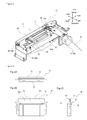
- a configuration example of the wiping unit 30 and a configuration example of a cleaning unit 40 to be described later will be shown in a perspective diagram (schematic diagram) of FIG. 3 .
- the wiping unit 30 (especially a blade 34) and the cleaning unit 40 are supported by the same supporting member (supporting member 2). According to this, a positional accuracy of relative arrangements of both the wiping unit 30 and the cleaning unit 40 can be improved.
- the wiping unit 30 is preferably arranged at one end portion in a horizontal scanning direction (left and right direction in FIG. 1 and FIG. 2 ), at a predetermined standby position for the ink jet head 20 to stand by. According to this, wiping of the nozzle surface 24 can be performed by using the standby time between the print processes of the ink jet head 20. Further, contaminating the recording medium M by unintended ink dripping caused by wiping can be prevented.
- the wiping unit 30 is configured by a wiper 36 having a blade 34 sandwiched from both surface sides by a supporting member 32 attached to a moving unit 38 so as to be reciprocatingly movable in a predetermined range (which is herein between A and B in FIG. 3 ).
- a configuration example of the wiper 36 is shown in diagrams of three sides (schematic diagrams) of FIG. 4A to FIG. 4C .
- FIG. 4A is a plan diagram
- FIG. 4B is a front diagram
- FIG. 4C is a lateral side diagram.
- a distal end portion (upper end edge) 34a of the blade 34 is brought into contact with the nozzle surface 24 of the ink jet head 20 and the wiper 36 (that is, the blade 34) is moved in a predetermined direction by the moving unit 38 to perform wiping (wipe-off), and the ink adherent to the nozzle surface 24 including distal end portions (opening portions) of the nozzles 23 can be removed (see FIG. 5 ).
- the wiper 36 that is, the blade 34
- wiping wipe-off
- the blade 34 is preferably formed of a material satisfying characteristics such as having flexibility and strength by which ink removal is mechanically enabled, not damaging a surface of the nozzle surface 24, and having resistance against acidic or alkali cleaning liquid; for example, resin materials such as polypropylene, or rubber materials such as EPDM are used. However, no limitation is made to these materials.
- the blade 34 according to the present embodiment is formed in a substantially rectangular flat plate shape by using polypropylene, and is configured such that its distal end portion (upper end edge) 34a makes linear contact with the nozzle surface 24.
- the wiping unit 30 is configured such that an upper end portion of the supporting member 32 is formed at a lower position in a height direction than the distal end portion (upper end edge) 34a of the blade 34, and the upper end portion of the supporting member 32 has an upper surface 32a with a predetermined width in the front and back direction as well as the left and right direction. That is, the wiping unit 30 is configured to have step portions 33 protruding in the front and back direction and extending in the left and right direction at positions that are lower than the distal end portion of the blade 34 by a predetermined length on both surface sides of the blade 34 (see FIG. 4A to FIG. 4C ).
- the supporting member 32 is formed in a cuboid by using materials such as EPDM, and as shown in FIG. 5 , is configured to support the blade 34 so that the blade can deform (warp). Further, by having the step portions 33, a cleaning operation to be described later can effectively be performed.
- the moving unit 38 that moves the wiper 36 is configured by including a timing belt 38b that is wound on a drive roller (not shown) that is driven by a drive motor 38a and a driven roller (not shown), and is arranged at a position to clean the nozzle surface 24 of the ink jet head 20, for example, a predetermined position in the vicinity of a home position of the carriage 14 for scanning the ink jet head 20, so as to be able to move the wiper 36 while opposing it to the nozzle surface 24 with a certain interval from the nozzle surface 24 of the ink jet head 20.
- the drive motor 38a is configured for example of a pulse motor, and rotates the timing belt 38b forward and backward by switching its phase excitation forward and backward. It should be noted that, a position of the wiper 36 is detected for example by a position detection sensor (not shown).
- the cleaning unit 40 is for cleaning the blade 34 by performing pouring of the cleaning liquid on the wiper 36 (especially, the blade 34) (an operation to pour the cleaning liquid and wash).
- the cleaning liquid may suitably be selected according to a type of ink to be used, and liquid having an effect of swelling and removing the ink that has increased viscosity and solidified is suitable.
- acidic liquid and the like of about pH 1.5 to 4.0 containing organic carboxylic acid is used.
- the cleaning unit 40 is preferably arranged at a position where it matches with the wiping unit 30, that is, at one end portion in the horizontal scanning direction (the left and right direction in FIG. 1 and FIG. 2 ), at the predetermined standby position for the ink jet head 20 to stand by (see FIG. 1 and FIG. 2 ). According to this, it is possible to perform cleaning of the wiper 36 (blade 34) by using the standby time between the print processes of the ink jet head 20. Further, contaminating the recording medium M by dripping of the cleaning liquid or the ink can be prevented.
- the cleaning unit 40 is configured by including a cleaning liquid discharging pipe 42, a cleaning liquid guiding member 44, and a cleaning liquid tray 46.
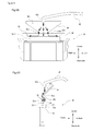
- FIG. 6A and FIG. 6B Schematic diagrams for explaining more detailed configuration example and cleaning operation are shown in FIG. 6A and FIG. 6B (where FIG. 6A is a front diagram, and FIG. 6B is a lateral side diagram).
- the cleaning liquid is stored in a storage portion (not shown), and is fed by liquid feeding unit such as a pump (not shown), passes through the flowing member (cleaning liquid discharging pipe) 42, and is discharged from an outflow portion (discharge port) 42a at an end portion of the cleaning liquid discharging pipe 42.
- the cleaning liquid discharging pipe 42 has the outflow portion (discharge port) 42a positioned above the cleaning liquid guiding member 44, and is arranged such that the discharged cleaning liquid flows over the cleaning liquid guiding member 44.
- a control member (as one example, a pump, a valve and the like) that controls an outflow of the cleaning liquid from the outflow portion (discharge port) 42a and stoppage thereof is provided (not shown). It should be noted that, the outflow (discharge) of the cleaning liquid is performed in a state where the ink jet head 20 is moved to the aforementioned standby position.
- the cleaning liquid guiding member 44 is a member that expands the pouring region of the cleaning liquid in a lateral direction (left and right direction) of the blade 34 of the wiper 36, and performs accurate positioning of the pouring position. More specifically, as shown in the front diagram (schematic diagram) of FIG. 6A , the cleaning liquid guiding member 44 is configured by having an angled surface 44b including a distal end portion (lower end edge) 44a with a predetermined width. As one example, the cleaning liquid guiding member 44 according to the present embodiment is formed in a flat plate shape having the inversed-trapezoidal angled surface 44b, however, no limitation is made to this configuration.
- the cleaning liquid guiding member 44 is arranged at a position where the distal end portion (upper end edge) 44a opposes and becomes parallel to the distal end portion (upper end edge) 34a of the blade 34 of the wiping unit 30, and the pouring of the cleaning liquid is to be performed on both front and back surfaces of the blade 34, that is, a position where the flow of the cleaning liquid flowing down from the cleaning liquid guiding member 44 is split by the distal end portion (upper end edge) 34a of the blade 34 and caused to flow on both of front and back surface sides of the blade 34.
- the ink will adhere to both front and back surfaces of the blade 34 by the wiping operation, however, the pouring can be performed simultaneously to both front and back surfaces of the blade 34 by simply discharging the cleaning liquid, so that the adherent ink can be washed off.
- This can be realized while the cleaning liquid discharging pipe 42 and the cleaning liquid guiding member 44 are fixed, so that a complicated mechanism for changing a discharging direction of the cleaning liquid to both surface sides of the blade 34 does not need to be provided, whereby a device configuration can be simplified, and device cost reduction can be achieved.
- the distal end portion (lower end edge) 44a of the cleaning liquid guiding member 44 includes a straight portion formed straight.
- the distal end portion (upper end edge) 34a of the blade 34 of the wiping unit 30 includes a straight portion formed straight.
- the straight portion (lower end edge 44a) of the cleaning liquid guiding member 44 and the straight portion (upper end edge 34a) of the blade 34 are arranged so as to be opposed and parallel to each other.
- the distal end portion (lower end edge) 44a of the cleaning liquid guiding member 44 is preferably formed with a width by which the cleaning liquid flowed out from the outflow portion (discharge port) 42a spreads over substantially an entire region in a width direction of the blade 34 (left and right direction in FIG. 6A ).
- distal end portion (lower end edge) 44a of the cleaning liquid guiding member and the distal end portion (upper end edge) 34a of the blade are preferably arranged at an interval by which the cleaning liquid flowed out from the outflow portion (discharge port) 42 spreads over substantially the entire region in the width direction of the blade 34 (left and right direction in FIG. 6A ).
- the cleaning liquid tray 46 is arranged below the discharge port of the cleaning liquid discharging pipe 42, the cleaning liquid guiding member 44, and the wiper 36 (including its moving range), and is a tray for collecting the cleaning liquid by which the pouring has been performed on the blade 34 of the wiper 36. It should be noted that a bottom surface of the cleaning liquid tray 46 is provided with a drainage hole 46a, and communicates with waste liquid tank (not shown).
- the ink jet recording device 1 discharges the ink downward from the nozzles 23 of the ink jet head 20 while moving the carriage 14 (head unit 18) reciprocatingly right and left along the Y bar 12 with respect to the recording medium M on the platen 10, and performs the print process on the recording medium M with a desired pattern.
- heating, ultraviolet ray irradiation, and the like are performed depending on the type of the ink, so that the ink adherent to the recording medium M comes to be in a desired hardened state.
- the recording medium M When printing on a predetermined forward and backward width of the recording medium M is completed, the recording medium M is moved forward by sliding, and the operation to discharge the ink from the ink jet head 20 and harden the same while reciprocatingly moving the carriage 14 (head unit 18) right and left is repeated again. Accordingly, the desired letters or image patterns are printed on the entire print region of the recording medium M.
- the discharged ink may gradually adhere to the nozzle surface 24, especially around peripheral portions of the nozzles 23, and further, an ink droplet may be formed by the adherent ink merging with each other. Moreover, such an ink droplet gradually hardens, and in some cases may become viscous ink, for example in a gel form.
- the ink droplet may drip onto the recording medium M, or cause clogging in the nozzles 23, whereby the print quality may be at the risk of being degraded, and therefore cleaning is performed periodically by performing wiping on the nozzle surface 24 of the ink jet head 20 using the wiping unit 30.
- Cleaning by the above wiping is started, for example, by being triggered when an operator has judged that maintenance of the nozzle surface 24 of the ink jet head 20 is necessary and has operated an operation panel (not shown), or when a controller (not shown) determined that an operating time (printing time) since the previous maintenance has reached a predetermined time.
- the carriage 14 head unit 18
- a horizontally driving mechanism based on actuating signals from a controller, and a state is assumed in which the nozzle surface 24 of the ink jet head 20 and the wiping unit 30 are opposed each other.
- the wiper 36 is moved by the moving unit 38 of the wiping unit 30. More specifically, the blade 34 of the wiper 36 is slid with respect to the nozzle surface 24 (moved by sliding in a predetermined direction in a state of making contact), whereby the nozzle surface 24 is wiped and the ink adherent to the nozzle surface 24 is removed (see FIG. 5 ).
- one wiping operation by the blade 34 is performed by a movement in one predetermined direction (an arrow direction in FIG. 5 ).
- the configuration may be employed that wiping is performed by a reciprocating movement.
- the ink removed by performing the wiping operation as above adheres to the blade 34 of the wiper 36.
- the adherent ink gradually hardens, and in some cases may become viscous ink, for example in a gel form. Accordingly, if the wiping operation is performed continuously in the state where the removed ink or the viscous ink formed by hardening of the removed ink is adherent to the blade 34, the ink conversely adheres to the nozzle surface 24 of the ink jet head 20 upon wiping, and may drip onto the recording medium M, or become the cause of clogging and color mixing by entering the nozzles 23, to degrade the print quality.
- cleaning is performed periodically by pouring the cleaning liquid on the blade 34 of the wiping unit 30 by using the cleaning unit 40 of the present embodiment. It should be noted that a time during which pouring of the cleaning liquid is performed is set suitably depending on the type of the ink.
- cleaning of the blade 34 by the cleaning unit 40 is performed for each wiping operation.
- the wiper 36 is moved to the predetermined position (the position A in FIG. 3 , as one example) by the moving unit 38 after the wiping operation has ended.
- the controller (not shown) outputs commands to cause the cleaning liquid to be discharged from the cleaning liquid discharging pipe 42.
- the cleaning liquid discharged from the cleaning liquid discharging pipe 42 falls down from the distal end portion (lower end edge) 44a in the state where the liquid width (width of the cleaning liquid) is expanded in the longitudinal direction of the blade 34 (left and right direction in FIG. 6A ) compared to when it has been discharged from the cleaning liquid discharging pipe 42, whereby the effect that the cleaning liquid is poured over a wider region in the left and right direction with respect to the plate surface of the blade 34 is obtained.
- the cleaning liquid that has been poured over the wider region in the left and right direction with respect to the plate surfaces of the blade 34 flows in the lateral direction (left and right direction in FIG. 6A ) over the step portions 33 (that is, the upper surface 32a of the supporting member 32), and the effect that the cleaning liquid reaches even wider region can be achieved.
- the cleaning liquid guiding member 44 is arranged at the position by which the flow of the cleaning liquid flowing down from the cleaning liquid guiding member 44 is split by the distal end portion (upper end edge) 34a of the blade 34 to flow on both front and back surfaces sides of the blade 34.
- cleaning of both front and back surfaces of the blade 34 can be performed at the same time just by discharging the cleaning liquid.
- the cleaning liquid discharged from the cleaning liquid discharging pipe 42 and poured onto the blade 34 of the wiper 36 is collected by the cleaning liquid tray 46, and flows into the waste liquid tank (not shown) from the drainage hole 46a.
- the wiping unit 30 and the cleaning unit 40 are provided to clean the blade 34 of the wiper 36 to which the ink has adhered, whereby clogging of the nozzles 23 of the ink jet head 20 and ink color mixing therein can be prevented to enable recording (printing) with high image quality.
- the ink jet recording device 1 disclosed herein is characteristic in including the wiping unit 30 that wipes off the ink by sliding the blade 34 on the nozzle surface 24 of the ink jet head 20; and the cleaning unit 40 that performs cleaning by pouring the cleaning liquid on the blade 34.
- the ink jet recording device 1 disclosed herein is characteristic in being an ink jet recording device in which liquid (ink) is supplied to the ink jet head 20 mounted on the carriage 14 that moves reciprocatingly in the horizontal scanning direction (left and right direction in FIGS. 1 and 2 ), and the liquid (ink) is discharged from the nozzles 23 of the ink jet head 20 onto the opposing recording medium M while the carriage 14 is moving reciprocatingly in the horizontal scanning direction
- the ink jet recording device including: the wiping unit 30 including the blade 34 that wipes off the ink on the nozzle surface 24 of the ink jet head 20 by sliding its distal end portion 34a on the nozzle surface 24 from the lower side; and the cleaning unit 40 including the outflow portion (discharge port) 42a that allows the cleaning liquid to flow out to the distal end portion 34a side of the blade 34.
- the ink jet recording device 1 since the nozzle surface 24 of the ink jet head 20 can be wiped by the blade 34 of the wiping unit 30, the ink adherent to the nozzle surface 24 can be removed. Moreover, the blade 34 that has performed wiping can be cleaned by the cleaning unit 40, and the ink adherent to the blade 34 can be removed; thus, clogging of the nozzles 23 and ink color mixing in the ink jet head 20 can be prevented even in cases where wiping is performed continuously.
- the cleaning unit 40 is preferably arranged at one end portion in the horizontal scanning direction (left and right direction in FIGS. 1 and 2 ), at the standby position for the ink jet head 20 to stand by.
- the cleaning unit 40 preferably allows the cleaning liquid to flow out to the distal end portion 34a side of the blade 34 in the state where the ink jet head 20 has moved to the standby position.
- wiping of the nozzle surface 24 and cleaning of the blade 34 of the wiping unit 30 can be performed by using standby time of the ink jet head 20. Further, in view of the risk that an undesirable influence may occur in the print process if wiping and cleaning are performed during the print process, such an undesirable influence can be prevented.
- the ink jet recording device further includes the storage portion (not shown) that stores the cleaning liquid; the flowing member (cleaning liquid discharging pipe) 42 having one end joined to the storage portion, including the outflow portion (discharge port) 42a at the other end, and configured to allow the cleaning liquid to flow through the inside thereof; and the controlling member (not shown) that controls the outflow of the cleaning liquid from the outflow portion (discharge port) 42a and the stoppage thereof.
- the cleaning liquid can be supplied from the storage portion provided in the ink jet recording device 1 to perform cleaning of the blade 34 of the wiping unit 30.
- the cleaning unit 40 preferably includes the cleaning liquid guiding member 44 between the distal end portion 34a of the blade 34 and the outflow portion (discharge port) 42a, the cleaning liquid guiding member 44 configured to expand the pouring region of the cleaning liquid and perform the positioning of the pouring position. According to this, it becomes possible to pour the cleaning liquid over a wider region in the longitudinal direction of the blade 34 with respect to the plate surface of the laterally elongate blade 34. Moreover, the pouring position, that is, the position where the cleaning liquid flows down can be set easily and highly accurately.
- the cleaning liquid guiding member 44 has its distal end portion (lower end edge) 44a opposed to the distal end portion (upper end edge) 34a of the blade 34 with respect to the blade 34 at the predetermined position, and is arranged at the position that splits the flow of the cleaning liquid to both front and back surface sides of the blade 34. According to this, pouring can be performed on both of the front and back surfaces of the blade 34 just by discharging the cleaning liquid, and the adherent ink can be washed off. Thus, a complicated mechanism for changing a discharging direction of the cleaning liquid to both surface sides of the blade 34 does not need to be provided, whereby a device configuration can be simplified, and device cost reduction can be achieved.
- the cleaning liquid guiding member 44 includes the straight portion (lower end edge 44a) of which distal end portion is formed straight
- the blade 34 includes the straight portion (upper end edge 34a) of which distal end portion is formed straight
- the straight portion (lower end edge 44a) of the cleaning liquid guiding member 44 and the straight portion (upper end edge 34a) of the blade 34 are arranged to be opposed and parallel to each other
- the cleaning liquid guiding member 44 has its distal end portion (lower end edge) 44a formed with the width by which the cleaning liquid flowed out from the outflow portion (discharge port) 42a spreads over substantially the entire region in the width direction of the blade 34.
- the cleaning liquid guiding member 44 includes the straight portion (lower end edge 44a) of which distal end portion is formed straight
- the blade 34 includes the straight portion (upper end edge 34a) of which distal end portion is formed straight
- the straight portion (lower end edge 44a) of the cleaning liquid guiding member 44 and the straight portion (upper end edge 34a) of the blade 34 are arranged to be opposed and parallel to each other, and the distal end portions 44a, 34a of the cleaning liquid guiding member 44 and the blade 34 are arranged at the interval by which the cleaning liquid flowed out from the outflow portion (discharge port) 42a spreads over substantially the entire region in the width direction of the blade 34.
- the cleaning liquid guiding member 44 is preferably supported by the supporting member 2 by which the wiping unit 30 is supported. According to this, since the cleaning liquid guiding member 44 and the wiping unit 30 (especially the blade 34) are supported by the same member (supporting member 2), the positional accuracy of arrangements of both the cleaning liquid guiding member 44 and the blade 34 can be improved.
- the wiping unit 30 preferably includes step portions 33 at both surface sides of the blade 34 at the positions that are lower than the distal end portion (upper end edge) 34a of the blade 34 by the predetermined length. According to this, the cleaning liquid that has been poured onto the blade 34 flows in left and right directions on the step portions 33 and reaches the wider region in the longitudinal direction, whereby the effect that the surface of the blade 34 is cleaned over a wide region can be obtained. Moreover, since flows of the cleaning liquid are generated from a center toward both the left direction and the right direction, the cleaning effect can further be increased.
Landscapes
- Ink Jet (AREA)
Abstract
Description
- The present invention relates to an ink jet recording device and more specifically to an ink jet recording device that performs recording by discharging liquid onto a medium from an ink jet head mounted on a carriage which scans over the medium.
- Various configurations have been known conventionally of ink jet recording devices (ink jet printers) that discharge ink from a nozzle of an ink jet head to record (print) desired letters and shapes on a recording medium.
- Generally, in an ink jet recording device, when a print process is performed, discharged ink may gradually adhere to a nozzle surface of an ink jet head, and further, an ink droplet may be formed by the adherent ink merging with each other. Moreover, such an ink droplet gradually hardens, and in some cases may become viscous ink, for example in a gel form. As above, if printing is performed continuously in a state where the viscous ink, the ink droplet and the like are adherent to the nozzle surface, a problem of print quality degrading may occur by the ink droplet dripping onto the recording medium, or by causing nozzle clogging. Thus, conventionally, a technique that performs cleaning by wiping the nozzle surface of the ink jet head by a blade and the like formed of rubber material and the like has been known (for example, see Patent Document 1).
- Patent Document 1:
JP 2005-014560 A - However, in a configuration exemplified in Patent Document 1, a state is assumed in which ink is adherent to a blade of a wiper by performing wiping. Thus, there has been a problem that, if wiping is continued in such a state, the ink adherent to the blade may enter a nozzle to cause clogging or ink color mixing.
- The present invention has been made in view of the above problem, and an object thereof is to provide an ink jet recording device that can clean a blade of a wiper to which ink is adherent, whereby nozzle clogging in an ink jet head and ink color mixing therein are prevented to enable recording with high image quality.
- As one embodiment, the problem may be solved by a solution as disclosed below.
- An ink jet recording device disclosed herein is characteristic in including a wiping unit that wipes off ink by sliding a blade on a nozzle surface of an ink jet head; and a cleaning unit that performs cleaning by pouring cleaning liquid on the blade.
- Further, an ink jet recording device disclosed herein is characteristic in being an ink jet recording device in which liquid is supplied to an ink jet head mounted on a carriage that moves reciprocatingly in a horizontal scanning direction and the liquid is discharged from a nozzle of the ink jet head onto an opposing recording medium while the carriage is moving reciprocatingly in the horizontal scanning direction, the ink jet recording device including: a wiping unit including a blade that wipes off ink on a nozzle surface of the ink jet head by sliding its distal end portion on the nozzle surface from a lower side; and a cleaning unit including an outflow portion that allows cleaning liquid to flow out to a distal end portion side of the blade.
- According to the ink jet recording device disclosed herein, since the nozzle surface of the ink jet head can be wiped by the blade of the wiping unit, the ink adherent to the nozzle surface can be removed. Moreover, the blade that has performed wiping can be cleaned by the cleaning unit, and the ink adherent to the blade can be removed; thus, the nozzle clogging and ink color mixing in the ink jet head can be prevented even in cases where wiping is performed continuously.
- Further, in the present invention, the cleaning unit is preferably arranged at one end portion in the horizontal scanning direction, at a standby position for the ink jet head to stand by.
- Further, in the present invention, the cleaning unit preferably allows the cleaning liquid to flow out to the distal end portion side of the blade in a state where the ink jet head has moved to the standby position.
- According to this, wiping of the nozzle surface and cleaning of the blade of the wiping unit can be performed by using the standby time of the ink jet head. Further, in view of a risk that an undesirable influence may occur in a print process if wiping and cleaning are performed during the print process, such an undesirable influence can be prevented.
- Further, in the present invention, preferably the ink jet recording device further includes a storage portion that stores the cleaning liquid; a flowing member having one end joined to the storage portion, including the outflow portion at the other end, and configured to allow the cleaning liquid to flow through an inside thereof; and a controlling member that controls an outflow of the cleaning liquid from the outflow portion and stoppage thereof. According to this, the cleaning liquid can be supplied from the storage portion provided in the ink jet recording device to perform cleaning of the blade of the wiping unit.
- Further, in the present invention, the cleaning unit preferably includes a cleaning liquid guiding member between a distal end portion of the blade and the outflow portion, the cleaning liquid guiding member configured to expand a pouring region of the cleaning liquid and perform positioning of a pouring position. According to this, it becomes possible to pour the cleaning liquid over a wider region in a longitudinal direction of the blade with respect to a plate surface of the laterally elongate blade. Moreover, a pouring position, that is, a position where the cleaning liquid flows down can be set easily and highly accurately.
- Further, in the present invention, preferably the cleaning liquid guiding member has its distal end portion opposed to the distal end portion of the blade with respect to the blade at a predetermined position, and is arranged at a position that splits a flow of the cleaning liquid to both front and back surface sides of the blade. According to this, pouring can be performed on both front and back surfaces of the blade just by discharging the cleaning liquid, and the adherent ink can be washed off. Thus, a complicated mechanism for changing a discharging direction of the cleaning liquid to both surface sides of the blade does not need to be provided, whereby a device configuration can be simplified, and device cost reduction can be achieved.
- Further, in the present invention, preferably the cleaning liquid guiding member includes a straight portion of which distal end portion is formed straight, the blade includes a straight portion of which distal end portion is formed straight, the straight portion of the cleaning liquid guiding member and the straight portion of the blade are arranged to be opposed and parallel to each other, and the cleaning liquid guiding member has its distal end portion formed with a width by which the cleaning liquid flowed out from the outflow portion spreads over substantially an entire region in a width direction of the blade.
- Further, in the present invention, preferably the cleaning liquid guiding member includes a straight portion of which distal end portion is formed straight, the blade includes a straight portion of which distal end portion is formed straight, the straight portion of the cleaning liquid guiding member and the straight portion of the blade are arranged to be opposed and parallel to each other, and the distal end portions of the cleaning liquid guiding member and the blade are arranged at an interval by which the cleaning liquid flowed out from the outflow portion spreads over substantially an entire region in a width direction of the blade.
- According to these, since it becomes possible to pour the cleaning liquid over substantially the entire region in the width direction (longitudinal direction) of the blade, an ink removal effect can be increased.
- Further, in the present invention, the cleaning liquid guiding member is preferably supported by a supporting member by which the wiping unit is supported. According to this, by the cleaning liquid guiding member and the wiping unit (especially the blade) being supported by the same supporting member, positional accuracy of arrangements of both the cleaning liquid guiding member and the blade can be improved.
- Further, in the present invention, the wiping unit preferably includes step portions on both surface sides of the blade at positions that are lower than a distal end portion of the blade by a predetermined length. According to this, the cleaning liquid that has been poured onto the blade flows in left and right directions on the step portions and reaches the wider region in the longitudinal direction, whereby an effect that the surface of the blade is cleaned over a wide region can be achieved. Moreover, since flows of the cleaning liquid from a center toward both the left direction and the right direction are generated, the cleaning effect can further be increased.
- According to the ink jet recording device disclosed herein, the wiping unit and the cleaning unit are provided to clean the blade of the wiper to which the ink has adhered, whereby nozzle clogging in the ink jet head and ink color mixing therein can be prevented, and recording with high image quality becomes possible.
-
-
FIG. 1 is a schematic diagram (plan diagram) showing an example of an ink jet recording device according to an embodiment of the present invention. -
FIG. 2 is a schematic diagram (lateral side diagram) of the ink jet recording device shown inFIG. 1 . -
FIG. 3 is a schematic diagram (perspective diagram) showing an example of a wiping unit and a cleaning unit of the ink jet recording device shown inFIG. 1 . -
FIG. 4A to FIG. 4C are schematic diagrams (diagrams of three sides) showing an example of a wiper of the wiping unit shown inFIG. 3 . -
FIG. 5 is a schematic diagram for explaining a sliding operation of the wiper shown inFIG. 4A to FIG. 4C . -
FIG. 6A and FIG. 6B are schematic diagrams for explaining a configuration and a cleaning operation of the cleaning unit shown inFIG. 3 . - Hereinbelow, embodiments of the present invention will be described in detail with reference to the drawings.
-
FIG. 1 shows a schematic diagram (plan diagram) of an ink jet recording device 1 according to this embodiment. Further,FIG. 2 shows a schematic diagram (lateral side diagram) of the ink jet recording device 1. For the sake of convenience of description, in respective diagrams, front and back, left and right, and up and down directions of the ink jet recording device 1 are shown by arrow directions. - It should be noted that, in all of the drawings for explaining the embodiments, members with an identical function are given the same reference sign, and repeating description thereof may in some cases be omitted.
- The ink jet recording device 1 is a device that performs a print process for letters, figures, and the like on a recording surface (print surface) of a recording medium M such as paper, cloth, and resin sheet (for example, formed of vinyl chloride, polyester, and the like) by discharging liquid (which is herein ink) from a nozzle of an ink jet head.
- The ink jet printer 1 according to the present embodiment has a
Y bar 12 bridged above aplaten 10 on which the recording medium M is to be mounted, in a direction (left and right direction inFIG. 1 ) that intersects orthogonally with a transfer direction of the recording medium M (forward direction inFIG. 1 ), and acarriage 14 is movably retained on thisY bar 12. Due to this, thecarriage 14 is configured to be movable in the left and right direction by being guided by theY bar 12. It should be noted that thecarriage 14 is joined to a traction mechanism using a wire, a ball, and the like, and is configured to be capable of moving in the left and right direction by controlling driving of a prime mover such as a motor. - This
carriage 14 has fixed thereon ahead unit 18, on which anink jet head 20 configured to discharge ink droplets is mounted. - The
ink jet head 20 is provided with anozzle plate 22 on which a plurality ofnozzles 23 configured to discharge ink droplets is formed (seeFIG. 2 andFIG. 5 ). Further, anozzle surface 24 from where ink droplets are discharged is formed on a surface of thenozzle plate 22 on a side of theplaten 10 and the recording medium M. It should be noted that a type of the ink is not particularly limited and ink for ink jet printing such as UV ink and latex ink may be used. - Here, in the present embodiment, a case of using the UV ink that cures by UV (ultraviolet ray) irradiation will be exemplified. Thus, the
head unit 18 hasUV irradiators 16 that deliver UV fixed on both sides in the left and right direction. It should be noted that, in case of using ink other than the UV ink (for example, latex ink and the like), theUV irradiators 16 may not be provided in the configuration. - By the above configuration, the
head unit 18 and theUV irradiators 16 can be moved simultaneously in the left and right direction by moving thecarriage 14 in the left and right direction. Moreover, while moving thecarriage 14 in the left and right direction, the ink droplets are discharged from thehead unit 18 and the UV is delivered from theUV irradiators 16 so that the discharge of ink droplets and the curing of the ink droplets that has struck onto the recording medium M can be performed in a single scan. - Further, in the present embodiment, a wiping
unit 30 that wipes thenozzle surface 24 of theink jet head 20 is provided below theink jet head 20 when thehead unit 18 is moved to an end portion on one side (right side inFIG. 1 and FIG. 2 ). Here, a configuration example of the wipingunit 30 and a configuration example of acleaning unit 40 to be described later will be shown in a perspective diagram (schematic diagram) ofFIG. 3 . It should be noted that, as shown inFIG. 3 , the wiping unit 30 (especially a blade 34) and thecleaning unit 40 are supported by the same supporting member (supporting member 2). According to this, a positional accuracy of relative arrangements of both thewiping unit 30 and thecleaning unit 40 can be improved. - In the present embodiment, the wiping
unit 30 is preferably arranged at one end portion in a horizontal scanning direction (left and right direction inFIG. 1 and FIG. 2 ), at a predetermined standby position for theink jet head 20 to stand by. According to this, wiping of thenozzle surface 24 can be performed by using the standby time between the print processes of theink jet head 20. Further, contaminating the recording medium M by unintended ink dripping caused by wiping can be prevented. - As shown in the perspective diagram (schematic diagram) of
FIG. 3 , the wipingunit 30 according to the present embodiment is configured by awiper 36 having ablade 34 sandwiched from both surface sides by a supportingmember 32 attached to a movingunit 38 so as to be reciprocatingly movable in a predetermined range (which is herein between A and B inFIG. 3 ). Here, a configuration example of thewiper 36 is shown in diagrams of three sides (schematic diagrams) ofFIG. 4A to FIG. 4C . It should be noted thatFIG. 4A is a plan diagram,FIG. 4B is a front diagram, andFIG. 4C is a lateral side diagram. - According to the above configuration, a distal end portion (upper end edge) 34a of the
blade 34 is brought into contact with thenozzle surface 24 of theink jet head 20 and the wiper 36 (that is, the blade 34) is moved in a predetermined direction by the movingunit 38 to perform wiping (wipe-off), and the ink adherent to thenozzle surface 24 including distal end portions (opening portions) of thenozzles 23 can be removed (seeFIG. 5 ). It should be noted that, although a specific wiping operation will be described later, one wiping operation on theblade 34 is performed by sliding in one predetermined direction (an arrow direction inFIG. 5 ). - Here, the
blade 34 is preferably formed of a material satisfying characteristics such as having flexibility and strength by which ink removal is mechanically enabled, not damaging a surface of thenozzle surface 24, and having resistance against acidic or alkali cleaning liquid; for example, resin materials such as polypropylene, or rubber materials such as EPDM are used. However, no limitation is made to these materials. As one example, theblade 34 according to the present embodiment is formed in a substantially rectangular flat plate shape by using polypropylene, and is configured such that its distal end portion (upper end edge) 34a makes linear contact with thenozzle surface 24. - Further, the wiping
unit 30 is configured such that an upper end portion of the supportingmember 32 is formed at a lower position in a height direction than the distal end portion (upper end edge) 34a of theblade 34, and the upper end portion of the supportingmember 32 has anupper surface 32a with a predetermined width in the front and back direction as well as the left and right direction. That is, the wipingunit 30 is configured to havestep portions 33 protruding in the front and back direction and extending in the left and right direction at positions that are lower than the distal end portion of theblade 34 by a predetermined length on both surface sides of the blade 34 (seeFIG. 4A to FIG. 4C ). As one example, the supportingmember 32 according to the present embodiment is formed in a cuboid by using materials such as EPDM, and as shown inFIG. 5 , is configured to support theblade 34 so that the blade can deform (warp). Further, by having thestep portions 33, a cleaning operation to be described later can effectively be performed. - Further, the moving
unit 38 that moves thewiper 36 is configured by including atiming belt 38b that is wound on a drive roller (not shown) that is driven by adrive motor 38a and a driven roller (not shown), and is arranged at a position to clean thenozzle surface 24 of theink jet head 20, for example, a predetermined position in the vicinity of a home position of thecarriage 14 for scanning theink jet head 20, so as to be able to move thewiper 36 while opposing it to thenozzle surface 24 with a certain interval from thenozzle surface 24 of theink jet head 20. - The
drive motor 38a is configured for example of a pulse motor, and rotates thetiming belt 38b forward and backward by switching its phase excitation forward and backward. It should be noted that, a position of thewiper 36 is detected for example by a position detection sensor (not shown). - Next, a
cleaning unit 40 characteristic of the present embodiment will be described. Thecleaning unit 40 is for cleaning theblade 34 by performing pouring of the cleaning liquid on the wiper 36 (especially, the blade 34) (an operation to pour the cleaning liquid and wash). It should be noted that the cleaning liquid may suitably be selected according to a type of ink to be used, and liquid having an effect of swelling and removing the ink that has increased viscosity and solidified is suitable. As one example, acidic liquid and the like of about pH 1.5 to 4.0 containing organic carboxylic acid is used. - In the present embodiment, the
cleaning unit 40 is preferably arranged at a position where it matches with the wipingunit 30, that is, at one end portion in the horizontal scanning direction (the left and right direction inFIG. 1 and FIG. 2 ), at the predetermined standby position for theink jet head 20 to stand by (seeFIG. 1 and FIG. 2 ). According to this, it is possible to perform cleaning of the wiper 36 (blade 34) by using the standby time between the print processes of theink jet head 20. Further, contaminating the recording medium M by dripping of the cleaning liquid or the ink can be prevented. - As shown in the perspective diagram (schematic diagram) of
FIG. 3 , thecleaning unit 40 according to the present embodiment is configured by including a cleaningliquid discharging pipe 42, a cleaningliquid guiding member 44, and a cleaningliquid tray 46. Schematic diagrams for explaining more detailed configuration example and cleaning operation are shown inFIG. 6A and FIG. 6B (whereFIG. 6A is a front diagram, andFIG. 6B is a lateral side diagram). The cleaning liquid is stored in a storage portion (not shown), and is fed by liquid feeding unit such as a pump (not shown), passes through the flowing member (cleaning liquid discharging pipe) 42, and is discharged from an outflow portion (discharge port) 42a at an end portion of the cleaningliquid discharging pipe 42. Here, the cleaningliquid discharging pipe 42 has the outflow portion (discharge port) 42a positioned above the cleaningliquid guiding member 44, and is arranged such that the discharged cleaning liquid flows over the cleaningliquid guiding member 44. Further, a control member (as one example, a pump, a valve and the like) that controls an outflow of the cleaning liquid from the outflow portion (discharge port) 42a and stoppage thereof is provided (not shown). It should be noted that, the outflow (discharge) of the cleaning liquid is performed in a state where theink jet head 20 is moved to the aforementioned standby position. - The cleaning
liquid guiding member 44 is a member that expands the pouring region of the cleaning liquid in a lateral direction (left and right direction) of theblade 34 of thewiper 36, and performs accurate positioning of the pouring position. More specifically, as shown in the front diagram (schematic diagram) ofFIG. 6A , the cleaningliquid guiding member 44 is configured by having anangled surface 44b including a distal end portion (lower end edge) 44a with a predetermined width. As one example, the cleaningliquid guiding member 44 according to the present embodiment is formed in a flat plate shape having the inversed-trapezoidalangled surface 44b, however, no limitation is made to this configuration. - Further, as shown in the lateral side diagram (schematic diagram) of
FIG. 6B , in a state where thewiper 36 is moved to the predetermined position (position of A inFIG. 3 , as one example) and the pouring of the cleaning liquid is to be performed on theblade 34 of thewiper 36, the cleaningliquid guiding member 44 is arranged at a position where the distal end portion (upper end edge) 44a opposes and becomes parallel to the distal end portion (upper end edge) 34a of theblade 34 of the wipingunit 30, and the pouring of the cleaning liquid is to be performed on both front and back surfaces of theblade 34, that is, a position where the flow of the cleaning liquid flowing down from the cleaningliquid guiding member 44 is split by the distal end portion (upper end edge) 34a of theblade 34 and caused to flow on both of front and back surface sides of theblade 34. - According to the above configuration, as shown in the front diagram (schematic diagram) of
FIG. 6A , an effect that the cleaning liquid that has been discharged from the cleaningliquid discharging pipe 42, by flowing on theangled surface 44b, flows down from the distal end portion (lower end edge) 44a in a state where the lateral width (width in the left and right direction ofFIG. 6A ) is widened compared to when it has been discharged is generated. That is, the cleaning liquid can be poured over a wider region (region wider in the left and right direction) with respect to the plate surface of the laterallyelongate blade 34. - Further, the ink will adhere to both front and back surfaces of the
blade 34 by the wiping operation, however, the pouring can be performed simultaneously to both front and back surfaces of theblade 34 by simply discharging the cleaning liquid, so that the adherent ink can be washed off. This can be realized while the cleaningliquid discharging pipe 42 and the cleaningliquid guiding member 44 are fixed, so that a complicated mechanism for changing a discharging direction of the cleaning liquid to both surface sides of theblade 34 does not need to be provided, whereby a device configuration can be simplified, and device cost reduction can be achieved. - Moreover, although the positioning for splitting the flow of the cleaning liquid needs to be performed highly accurately, in a case of configuring to pour the cleaning liquid on the
blade 34 of thewiper 36 directly from thedischarge port 42a of the cleaningliquid discharging pipe 42, a problem arises in that the positioning of thedischarge port 42a for generating the desired flow split becomes very difficult. However, in the present embodiment, by the configuration having the cleaningliquid guiding member 44, an effect that the positioning for generating the desired flow split becomes very easy can be obtained. - Especially, in the present embodiment, the distal end portion (lower end edge) 44a of the cleaning
liquid guiding member 44 includes a straight portion formed straight. Further, the distal end portion (upper end edge) 34a of theblade 34 of the wipingunit 30 includes a straight portion formed straight. Moreover, the straight portion (lower end edge 44a) of the cleaningliquid guiding member 44 and the straight portion (upper end edge 34a) of theblade 34 are arranged so as to be opposed and parallel to each other. - At this occasion, the distal end portion (lower end edge) 44a of the cleaning
liquid guiding member 44 is preferably formed with a width by which the cleaning liquid flowed out from the outflow portion (discharge port) 42a spreads over substantially an entire region in a width direction of the blade 34 (left and right direction inFIG. 6A ). - Further, the distal end portion (lower end edge) 44a of the cleaning liquid guiding member and the distal end portion (upper end edge) 34a of the blade are preferably arranged at an interval by which the cleaning liquid flowed out from the outflow portion (discharge port) 42 spreads over substantially the entire region in the width direction of the blade 34 (left and right direction in
FIG. 6A ). - According to these configurations, since it becomes possible to pour the cleaning liquid over substantially the entire region in the width direction (left and right direction in
FIG. 6A ) of the blade, the ink removal effect can be increased. - The cleaning
liquid tray 46 is arranged below the discharge port of the cleaningliquid discharging pipe 42, the cleaningliquid guiding member 44, and the wiper 36 (including its moving range), and is a tray for collecting the cleaning liquid by which the pouring has been performed on theblade 34 of thewiper 36. It should be noted that a bottom surface of the cleaningliquid tray 46 is provided with adrainage hole 46a, and communicates with waste liquid tank (not shown). - Next, an operation of the ink jet recording device having the above configuration will be described, mainly focusing on the wiping operation by the wiping
unit 30 and the cleaning operation by thecleaning unit 40. - In normal printing, the ink jet recording device 1 discharges the ink downward from the
nozzles 23 of theink jet head 20 while moving the carriage 14 (head unit 18) reciprocatingly right and left along theY bar 12 with respect to the recording medium M on theplaten 10, and performs the print process on the recording medium M with a desired pattern. At this occasion, heating, ultraviolet ray irradiation, and the like are performed depending on the type of the ink, so that the ink adherent to the recording medium M comes to be in a desired hardened state. - When printing on a predetermined forward and backward width of the recording medium M is completed, the recording medium M is moved forward by sliding, and the operation to discharge the ink from the
ink jet head 20 and harden the same while reciprocatingly moving the carriage 14 (head unit 18) right and left is repeated again. Accordingly, the desired letters or image patterns are printed on the entire print region of the recording medium M. - In the ink jet recording device 1, when the print process is performed, the discharged ink may gradually adhere to the
nozzle surface 24, especially around peripheral portions of thenozzles 23, and further, an ink droplet may be formed by the adherent ink merging with each other. Moreover, such an ink droplet gradually hardens, and in some cases may become viscous ink, for example in a gel form. Accordingly, if printing is continued in the state having the viscous ink and ink droplet and the like adhering to thenozzle surface 24 of theink jet head 20, the ink droplet may drip onto the recording medium M, or cause clogging in thenozzles 23, whereby the print quality may be at the risk of being degraded, and therefore cleaning is performed periodically by performing wiping on thenozzle surface 24 of theink jet head 20 using thewiping unit 30. - Cleaning by the above wiping is started, for example, by being triggered when an operator has judged that maintenance of the
nozzle surface 24 of theink jet head 20 is necessary and has operated an operation panel (not shown), or when a controller (not shown) determined that an operating time (printing time) since the previous maintenance has reached a predetermined time. - When cleaning is started by the above trigger, firstly, the carriage 14 (head unit 18) is moved to a position above the wiping
unit 30 by a horizontally driving mechanism based on actuating signals from a controller, and a state is assumed in which thenozzle surface 24 of theink jet head 20 and the wipingunit 30 are opposed each other. - Next, the
wiper 36 is moved by the movingunit 38 of the wipingunit 30. More specifically, theblade 34 of thewiper 36 is slid with respect to the nozzle surface 24 (moved by sliding in a predetermined direction in a state of making contact), whereby thenozzle surface 24 is wiped and the ink adherent to thenozzle surface 24 is removed (seeFIG. 5 ). It should be noted that, in the present embodiment, one wiping operation by theblade 34 is performed by a movement in one predetermined direction (an arrow direction inFIG. 5 ). However, no limitation is made hereto, and the configuration may be employed that wiping is performed by a reciprocating movement. - Accordingly, a clean state in which no ink droplet or viscous ink is adherent to the
nozzle surface 24 and insides of thenozzles 23 of theink jet head 20 can be assumed by performing wiping by the wipingunit 30, whereby ink discharge from thenozzles 23 is performed accurately, and further, unnecessary ink dripping can be prevented, so that high quality printing becomes possible. - On the other hand, the ink removed by performing the wiping operation as above adheres to the
blade 34 of thewiper 36. The adherent ink gradually hardens, and in some cases may become viscous ink, for example in a gel form. Accordingly, if the wiping operation is performed continuously in the state where the removed ink or the viscous ink formed by hardening of the removed ink is adherent to theblade 34, the ink conversely adheres to thenozzle surface 24 of theink jet head 20 upon wiping, and may drip onto the recording medium M, or become the cause of clogging and color mixing by entering thenozzles 23, to degrade the print quality. - To solve this problem, cleaning (washing) is performed periodically by pouring the cleaning liquid on the
blade 34 of the wipingunit 30 by using thecleaning unit 40 of the present embodiment. It should be noted that a time during which pouring of the cleaning liquid is performed is set suitably depending on the type of the ink. - As one example, cleaning of the
blade 34 by thecleaning unit 40 is performed for each wiping operation. As to the cleaning operation, more specifically, thewiper 36 is moved to the predetermined position (the position A inFIG. 3 , as one example) by the movingunit 38 after the wiping operation has ended. When the position detection sensor (not shown) detects that thewiper 36 has moves to the predetermined position, the controller (not shown) outputs commands to cause the cleaning liquid to be discharged from the cleaningliquid discharging pipe 42. - Next, by flowing on the
angled surface 44b of the cleaningliquid guiding member 44, the cleaning liquid discharged from the cleaningliquid discharging pipe 42 falls down from the distal end portion (lower end edge) 44a in the state where the liquid width (width of the cleaning liquid) is expanded in the longitudinal direction of the blade 34 (left and right direction inFIG. 6A ) compared to when it has been discharged from the cleaningliquid discharging pipe 42, whereby the effect that the cleaning liquid is poured over a wider region in the left and right direction with respect to the plate surface of theblade 34 is obtained. - In addition to this, in the present embodiment, due to the configuration including the
step portions 33 protruding in the front and back direction and extending in the left and right direction at positions that are lower than the distal end portion (upper end edge) 34a of theblade 34 by a predetermined length on both surface sides of theblade 34, the cleaning liquid that has been poured over the wider region in the left and right direction with respect to the plate surfaces of theblade 34 flows in the lateral direction (left and right direction inFIG. 6A ) over the step portions 33 (that is, theupper surface 32a of the supporting member 32), and the effect that the cleaning liquid reaches even wider region can be achieved. - With the above acting synergistically, a prominent effect that cleaning is performed on the surfaces of the
blade 34 not locally, but entirely can be achieved. Moreover, by flows of the cleaning liquid being generated from a center toward both the left direction and the right direction are generated, the wash-off effect can further be increased. - Further, as mentioned above, the cleaning
liquid guiding member 44 is arranged at the position by which the flow of the cleaning liquid flowing down from the cleaningliquid guiding member 44 is split by the distal end portion (upper end edge) 34a of theblade 34 to flow on both front and back surfaces sides of theblade 34. Thus, cleaning of both front and back surfaces of theblade 34 can be performed at the same time just by discharging the cleaning liquid. - It should be noted that the cleaning liquid discharged from the cleaning
liquid discharging pipe 42 and poured onto theblade 34 of thewiper 36 is collected by the cleaningliquid tray 46, and flows into the waste liquid tank (not shown) from thedrainage hole 46a. - As described above, according to the ink jet recording device 1 disclosed herein, the wiping
unit 30 and thecleaning unit 40 are provided to clean theblade 34 of thewiper 36 to which the ink has adhered, whereby clogging of thenozzles 23 of theink jet head 20 and ink color mixing therein can be prevented to enable recording (printing) with high image quality. - Further, especially, the characteristic working effects as below are achieved by the present embodiment.
- The ink jet recording device 1 disclosed herein is characteristic in including the
wiping unit 30 that wipes off the ink by sliding theblade 34 on thenozzle surface 24 of theink jet head 20; and thecleaning unit 40 that performs cleaning by pouring the cleaning liquid on theblade 34. - Further, the ink jet recording device 1 disclosed herein is characteristic in being an ink jet recording device in which liquid (ink) is supplied to the
ink jet head 20 mounted on thecarriage 14 that moves reciprocatingly in the horizontal scanning direction (left and right direction inFIGS. 1 and 2 ), and the liquid (ink) is discharged from thenozzles 23 of theink jet head 20 onto the opposing recording medium M while thecarriage 14 is moving reciprocatingly in the horizontal scanning direction, the ink jet recording device including: the wipingunit 30 including theblade 34 that wipes off the ink on thenozzle surface 24 of theink jet head 20 by sliding itsdistal end portion 34a on thenozzle surface 24 from the lower side; and thecleaning unit 40 including the outflow portion (discharge port) 42a that allows the cleaning liquid to flow out to thedistal end portion 34a side of theblade 34. - According to the ink jet recording device 1 disclosed herein, since the
nozzle surface 24 of theink jet head 20 can be wiped by theblade 34 of the wipingunit 30, the ink adherent to thenozzle surface 24 can be removed. Moreover, theblade 34 that has performed wiping can be cleaned by thecleaning unit 40, and the ink adherent to theblade 34 can be removed; thus, clogging of thenozzles 23 and ink color mixing in theink jet head 20 can be prevented even in cases where wiping is performed continuously. - Further, in the present invention, the
cleaning unit 40 is preferably arranged at one end portion in the horizontal scanning direction (left and right direction inFIGS. 1 and 2 ), at the standby position for theink jet head 20 to stand by. - Further, in the present invention, the
cleaning unit 40 preferably allows the cleaning liquid to flow out to thedistal end portion 34a side of theblade 34 in the state where theink jet head 20 has moved to the standby position. - According to this, wiping of the
nozzle surface 24 and cleaning of theblade 34 of the wipingunit 30 can be performed by using standby time of theink jet head 20. Further, in view of the risk that an undesirable influence may occur in the print process if wiping and cleaning are performed during the print process, such an undesirable influence can be prevented. - Further, in the present invention, preferably the ink jet recording device further includes the storage portion (not shown) that stores the cleaning liquid; the flowing member (cleaning liquid discharging pipe) 42 having one end joined to the storage portion, including the outflow portion (discharge port) 42a at the other end, and configured to allow the cleaning liquid to flow through the inside thereof; and the controlling member (not shown) that controls the outflow of the cleaning liquid from the outflow portion (discharge port) 42a and the stoppage thereof. According to this, the cleaning liquid can be supplied from the storage portion provided in the ink jet recording device 1 to perform cleaning of the
blade 34 of the wipingunit 30. - Further, in the present invention, the
cleaning unit 40 preferably includes the cleaningliquid guiding member 44 between thedistal end portion 34a of theblade 34 and the outflow portion (discharge port) 42a, the cleaningliquid guiding member 44 configured to expand the pouring region of the cleaning liquid and perform the positioning of the pouring position. According to this, it becomes possible to pour the cleaning liquid over a wider region in the longitudinal direction of theblade 34 with respect to the plate surface of the laterallyelongate blade 34. Moreover, the pouring position, that is, the position where the cleaning liquid flows down can be set easily and highly accurately. - Further, in the present invention, preferably the cleaning
liquid guiding member 44 has its distal end portion (lower end edge) 44a opposed to the distal end portion (upper end edge) 34a of theblade 34 with respect to theblade 34 at the predetermined position, and is arranged at the position that splits the flow of the cleaning liquid to both front and back surface sides of theblade 34. According to this, pouring can be performed on both of the front and back surfaces of theblade 34 just by discharging the cleaning liquid, and the adherent ink can be washed off. Thus, a complicated mechanism for changing a discharging direction of the cleaning liquid to both surface sides of theblade 34 does not need to be provided, whereby a device configuration can be simplified, and device cost reduction can be achieved. - Further, in the present invention, preferably the cleaning
liquid guiding member 44 includes the straight portion (lower end edge 44a) of which distal end portion is formed straight, theblade 34 includes the straight portion (upper end edge 34a) of which distal end portion is formed straight, the straight portion (lower end edge 44a) of the cleaningliquid guiding member 44 and the straight portion (upper end edge 34a) of theblade 34 are arranged to be opposed and parallel to each other, and the cleaningliquid guiding member 44 has its distal end portion (lower end edge) 44a formed with the width by which the cleaning liquid flowed out from the outflow portion (discharge port) 42a spreads over substantially the entire region in the width direction of theblade 34. - Further, in the present invention, preferably the cleaning
liquid guiding member 44 includes the straight portion (lower end edge 44a) of which distal end portion is formed straight, theblade 34 includes the straight portion (upper end edge 34a) of which distal end portion is formed straight, the straight portion (lower end edge 44a) of the cleaningliquid guiding member 44 and the straight portion (upper end edge 34a) of theblade 34 are arranged to be opposed and parallel to each other, and thedistal end portions liquid guiding member 44 and theblade 34 are arranged at the interval by which the cleaning liquid flowed out from the outflow portion (discharge port) 42a spreads over substantially the entire region in the width direction of theblade 34. - According to these, since it becomes possible to pour the cleaning liquid over substantially the entire region in the width direction (longitudinal direction) of the
blade 34 for cleaning, the ink removal effect can be increased. - Further, in the present invention, the cleaning
liquid guiding member 44 is preferably supported by the supportingmember 2 by which thewiping unit 30 is supported. According to this, since the cleaningliquid guiding member 44 and the wiping unit 30 (especially the blade 34) are supported by the same member (supporting member 2), the positional accuracy of arrangements of both the cleaningliquid guiding member 44 and theblade 34 can be improved. - Further, in the present invention, the wiping
unit 30 preferably includesstep portions 33 at both surface sides of theblade 34 at the positions that are lower than the distal end portion (upper end edge) 34a of theblade 34 by the predetermined length. According to this, the cleaning liquid that has been poured onto theblade 34 flows in left and right directions on thestep portions 33 and reaches the wider region in the longitudinal direction, whereby the effect that the surface of theblade 34 is cleaned over a wide region can be obtained. Moreover, since flows of the cleaning liquid are generated from a center toward both the left direction and the right direction, the cleaning effect can further be increased. - It should be noted that the present invention is not limited to the embodiments described above, and it goes without saying that it can be modified in various ways within the scope that does not go beyond the present invention.
-
- 1 Ink jet recording device
- 2 Supporting member
- 10 Platen
- 12 Y bar
- 14 Carriage
- 18 Head unit
- 20 Ink jet head
- 23 Nozzle
- 24 Nozzle surface
- 30 Wiping unit
- 32 Supporting member
- 34 Blade
- 36 Wiper
- 38 Moving unit
- 40 Cleaning unit
- 42 Flowing member (cleaning liquid discharging pipe)
- 42a Outflow portion (discharge port)
- 44 Cleaning liquid guiding member
- 46 Cleaning liquid tray
- M Recording medium
Claims (11)
- An ink jet recording device comprising:a wiping unit that wipes off ink by sliding a blade on a nozzle surface of an ink jet head; anda cleaning unit that performs cleaning by pouring cleaning liquid on the blade.
- An ink jet recording device in which liquid is supplied to an ink jet head mounted on a carriage that moves reciprocatingly in a main scanning direction, and the liquid is discharged from a nozzle of the ink jet head onto an opposing recording medium while the carriage is moving reciprocatingly in the main scanning direction, the ink jet recording device comprising:a wiping unit including a blade that wipes off ink on a nozzle surface of the ink jet head by sliding its distal end portion on the nozzle surface from a lower side; anda cleaning unit including an outflow portion that allows cleaning liquid to flow out to a distal end portion side of the blade.
- The ink jet recording device according to claim 2, wherein the cleaning unit is arranged at one end portion in the main scanning direction, at a standby position for the ink jet head to stand by.
- The ink jet recording device according to claim 3, wherein the cleaning unit allows the cleaning liquid to flow out to the distal end portion side of the blade in a state where the ink jet head has moved to the standby position.
- The ink jet recording device according to claim 2, further comprising:a storage portion that stores the cleaning liquid;
a flowing member having one end joined to the storage portion, including the outflow portion at the other end, and configured to allow the cleaning liquid to flow through an inside thereof; and
a controlling member that controls an outflow of the cleaning liquid from the outflow portion and stoppage thereof. - The ink jet recording device according to any one of claims 1 to 5, wherein the cleaning unit includes a cleaning liquid guiding member, the cleaning liquid guiding member configured to expand a pouring region of the cleaning liquid, and perform positioning of a pouring position.
- The ink jet recording device according to claim 6, wherein the cleaning liquid guiding member has its distal end portion oppose the distal end portion of the blade with respect to the blade at a predetermined position, and is arranged at a position that splits a flow of the cleaning liquid to both front and back surface sides of the blade.
- The ink jet recording device according to claim 6, wherein
the cleaning liquid guiding member includes a straight portion of which distal end portion is formed straight,
the blade includes a straight portion of which distal end portion is formed straight
the straight portion of the cleaning liquid guiding member and the straight portion of the blade are arranged to be opposed and parallel to each other, and
the cleaning liquid guiding member has its distal end portion formed with a width by which the cleaning liquid flowed out from the outflow portion spreads over substantially an entire region in a width direction of the blade. - The ink jet recording device according to claim 6, wherein
the cleaning liquid guiding member includes a straight portion of which distal end portion is formed straight,
the blade includes a straight portion of which distal end portion is formed straight,
the straight portion of the cleaning liquid guiding member and the straight portion of the blade are arranged to be opposed and parallel to each other, and
the distal end portions of the cleaning liquid guiding member and the blade are arranged at an interval by which the cleaning liquid flowed out from the outflow portion spreads over substantially an entire region in a width direction of the blade. - The ink jet recording device according to claim 6, wherein the cleaning liquid guiding member is supported by a supporting portion by which the wiping unit is supported.
- The ink jet recording device according to claim 1, wherein the wiping unit includes step portions at both surface sides of the blade at positions that are lower than a distal end portion of the blade by a predetermined length.
Applications Claiming Priority (2)
| Application Number | Priority Date | Filing Date | Title |
|---|---|---|---|
| JP2012239804A JP6111479B2 (en) | 2012-10-31 | 2012-10-31 | Inkjet recording device |
| PCT/JP2013/079339 WO2014069494A1 (en) | 2012-10-31 | 2013-10-30 | Inkjet printing device |
Publications (2)
| Publication Number | Publication Date |
|---|---|
| EP2915671A1 true EP2915671A1 (en) | 2015-09-09 |
| EP2915671A4 EP2915671A4 (en) | 2016-10-12 |
Family
ID=50627394
Family Applications (1)
| Application Number | Title | Priority Date | Filing Date |
|---|---|---|---|
| EP13850916.1A Withdrawn EP2915671A4 (en) | 2012-10-31 | 2013-10-30 | Inkjet printing device |
Country Status (5)
| Country | Link |
|---|---|
| US (1) | US9457577B2 (en) |
| EP (1) | EP2915671A4 (en) |
| JP (1) | JP6111479B2 (en) |
| CN (1) | CN104768762B (en) |
| WO (1) | WO2014069494A1 (en) |
Cited By (3)
| Publication number | Priority date | Publication date | Assignee | Title |
|---|---|---|---|---|
| US9498959B2 (en) | 2014-11-05 | 2016-11-22 | Seiko Epson Corporation | Maintenance unit and liquid ejection device |
| CN106739513A (en) * | 2017-01-11 | 2017-05-31 | 黑迈数码科技(嘉善)有限公司 | A kind of full-automatic spray head maintenance system of digital conduction band stamp printer |
| WO2019013768A1 (en) * | 2017-07-11 | 2019-01-17 | Hewlett-Packard Development Company, L.P. | Fluid actuator evaluation independent of actuation state |
Families Citing this family (15)
| Publication number | Priority date | Publication date | Assignee | Title |
|---|---|---|---|---|
| CN104191821B (en) * | 2014-09-15 | 2016-03-16 | 郑州新世纪数码打印科技有限公司 | Two shower nozzle ink station of pictorial machine |
| US9878544B2 (en) * | 2014-12-05 | 2018-01-30 | Dover Europe Sarl | Ink-jet printer with wiper assembly |
| JP6817720B2 (en) * | 2016-05-20 | 2021-01-20 | 株式会社写真化学 | Tablet printing device |
| TWI698284B (en) * | 2017-11-20 | 2020-07-11 | 研能科技股份有限公司 | Printhead cleaning module |
| JP7023774B2 (en) * | 2018-04-11 | 2022-02-22 | 株式会社ミマキエンジニアリング | inkjet printer |
| JP7131149B2 (en) * | 2018-07-11 | 2022-09-06 | 京セラドキュメントソリューションズ株式会社 | Inkjet recording device |
| EP3653387A1 (en) * | 2018-11-16 | 2020-05-20 | Canon Production Printing Holding B.V. | Method of cleaning of surface of an object |
| KR20210114095A (en) * | 2020-03-09 | 2021-09-23 | 삼성디스플레이 주식회사 | Apparatus for cleaning a blade, method for cleaning a blade, and apparatus for manufacturing a display device |
| JP7613224B2 (en) * | 2021-04-15 | 2025-01-15 | 京セラドキュメントソリューションズ株式会社 | Recording head and inkjet recording device |
| JP2024131229A (en) * | 2023-03-15 | 2024-09-30 | 株式会社ミマキエンジニアリング | Printer |
| JP2024158035A (en) * | 2023-04-27 | 2024-11-08 | 京セラドキュメントソリューションズ株式会社 | Inkjet recording device |
| JP2025008788A (en) * | 2023-07-06 | 2025-01-20 | 京セラドキュメントソリューションズ株式会社 | Inkjet recording device |
| CN117183584B (en) * | 2023-08-22 | 2026-03-31 | 广东阿诺捷喷墨科技有限公司 | An automatic cleaning inkjet printer |
| JP2025043571A (en) * | 2023-09-19 | 2025-04-01 | 京セラドキュメントソリューションズ株式会社 | Inkjet recording device |
| JP2025142636A (en) * | 2024-03-18 | 2025-10-01 | 京セラドキュメントソリューションズ株式会社 | Maintenance device and inkjet recording device |
Family Cites Families (8)
| Publication number | Priority date | Publication date | Assignee | Title |
|---|---|---|---|---|
| US5907335A (en) * | 1996-11-13 | 1999-05-25 | Hewlett-Packard Company | Wet wiping printhead cleaning system using a non-contact technique for applying a printhead treatment fluid |
| JP3897453B2 (en) * | 1998-06-17 | 2007-03-22 | キヤノン株式会社 | Inkjet recording device |
| JP2001191543A (en) * | 2000-01-07 | 2001-07-17 | Seiko Instruments Inc | Inkjet head wiping device |
| JP2005014560A (en) | 2003-06-30 | 2005-01-20 | Mimaki Engineering Co Ltd | Mechanism for removing ink volatile matter from undersurface of inkjet head of inkjet printer |
| JP4715522B2 (en) * | 2006-01-11 | 2011-07-06 | セイコーエプソン株式会社 | Liquid ejector |
| US7766449B2 (en) * | 2006-03-27 | 2010-08-03 | Brother Kogyo Kabushiki Kaisha | Ink-jet recording apparatus |
| JP4861129B2 (en) * | 2006-11-08 | 2012-01-25 | 株式会社ミヤコシ | Printhead wiping device |
| JP5668918B2 (en) * | 2010-11-18 | 2015-02-12 | セイコーエプソン株式会社 | Liquid ejecting apparatus and method for wiping nozzle forming surface of liquid ejecting head |
-
2012
- 2012-10-31 JP JP2012239804A patent/JP6111479B2/en active Active
-
2013
- 2013-10-30 CN CN201380056854.5A patent/CN104768762B/en active Active
- 2013-10-30 EP EP13850916.1A patent/EP2915671A4/en not_active Withdrawn
- 2013-10-30 US US14/438,635 patent/US9457577B2/en active Active
- 2013-10-30 WO PCT/JP2013/079339 patent/WO2014069494A1/en not_active Ceased
Cited By (5)
| Publication number | Priority date | Publication date | Assignee | Title |
|---|---|---|---|---|
| US9498959B2 (en) | 2014-11-05 | 2016-11-22 | Seiko Epson Corporation | Maintenance unit and liquid ejection device |
| CN106739513A (en) * | 2017-01-11 | 2017-05-31 | 黑迈数码科技(嘉善)有限公司 | A kind of full-automatic spray head maintenance system of digital conduction band stamp printer |
| CN106739513B (en) * | 2017-01-11 | 2018-12-07 | 黑迈数码科技(嘉善)有限公司 | A kind of full-automatic spray head maintenance system of number conduction band stamp printer |
| WO2019013768A1 (en) * | 2017-07-11 | 2019-01-17 | Hewlett-Packard Development Company, L.P. | Fluid actuator evaluation independent of actuation state |
| US11052656B2 (en) | 2017-07-11 | 2021-07-06 | Hewlett-Packard Development Company, L.P. | Fluid actuator evaluation independent of actuation state |
Also Published As
| Publication number | Publication date |
|---|---|
| JP6111479B2 (en) | 2017-04-12 |
| EP2915671A4 (en) | 2016-10-12 |
| WO2014069494A1 (en) | 2014-05-08 |
| US9457577B2 (en) | 2016-10-04 |
| JP2014087991A (en) | 2014-05-15 |
| US20150273836A1 (en) | 2015-10-01 |
| CN104768762A (en) | 2015-07-08 |
| CN104768762B (en) | 2016-10-19 |
Similar Documents
| Publication | Publication Date | Title |
|---|---|---|
| US9457577B2 (en) | Ink jet recording device with inkjet head cleaning member | |
| CN104029488B (en) | The cleaning method of liquid ejection apparatus and ejecting head | |
| CN101844445B (en) | Liquid spraying device and maintaining method thereof | |
| US9498958B2 (en) | Liquid jetting apparatus | |
| CN104029484B (en) | Liquid injection apparatus | |
| EP4140751B1 (en) | Inkjet recording device | |
| JP6102611B2 (en) | Liquid ejecting apparatus and wiping method | |
| US9162463B2 (en) | Liquid jetting apparatus and method for cleaning wiper | |
| US9527294B2 (en) | Printer | |
| WO2010095363A1 (en) | Printer device and method of maintaining same | |
| JP7628672B2 (en) | Inkjet printer | |
| JP6393519B2 (en) | Liquid wiping device and inkjet recording apparatus | |
| JP2017071135A (en) | Cleaning device and ink jet printer with the same | |
| US9421778B2 (en) | Liquid discharge apparatus | |
| JP4947009B2 (en) | Liquid ejection device | |
| KR20190112150A (en) | Liquid dispenser | |
| JP4666946B2 (en) | Discharge port surface cleaning method, liquid discharge apparatus, and probe carrier manufacturing apparatus | |
| JP2010105310A (en) | Liquid jet device | |
| CN115139668B (en) | Control method of ink-jet printing process | |
| JP2023046650A (en) | Printing device and cleaning method for wiping member | |
| US9434170B1 (en) | Print device | |
| JP2013193408A (en) | Droplet discharge device | |
| JP2001096757A (en) | Inkjet printer | |
| JP5668383B2 (en) | Cleaning device in fluid ejection device, fluid ejection device, and cleaning method in fluid ejection device | |
| JP2012086368A (en) | Wiping method, wiping control device and liquid injection device |
Legal Events
| Date | Code | Title | Description |
|---|---|---|---|
| PUAI | Public reference made under article 153(3) epc to a published international application that has entered the european phase |
Free format text: ORIGINAL CODE: 0009012 |
|
| 17P | Request for examination filed |
Effective date: 20150601 |
|
| AK | Designated contracting states |
Kind code of ref document: A1 Designated state(s): AL AT BE BG CH CY CZ DE DK EE ES FI FR GB GR HR HU IE IS IT LI LT LU LV MC MK MT NL NO PL PT RO RS SE SI SK SM TR |
|
| AX | Request for extension of the european patent |
Extension state: BA ME |
|
| DAX | Request for extension of the european patent (deleted) | ||
| RA4 | Supplementary search report drawn up and despatched (corrected) |
Effective date: 20160912 |
|
| RIC1 | Information provided on ipc code assigned before grant |
Ipc: B41J 2/165 20060101AFI20160906BHEP |
|
| STAA | Information on the status of an ep patent application or granted ep patent |
Free format text: STATUS: THE APPLICATION HAS BEEN WITHDRAWN |
|
| 18W | Application withdrawn |
Effective date: 20161223 |