EP2915605A1 - Method for machining seal-mounting groove in metal plate - Google Patents
Method for machining seal-mounting groove in metal plate Download PDFInfo
- Publication number
- EP2915605A1 EP2915605A1 EP13851419.5A EP13851419A EP2915605A1 EP 2915605 A1 EP2915605 A1 EP 2915605A1 EP 13851419 A EP13851419 A EP 13851419A EP 2915605 A1 EP2915605 A1 EP 2915605A1
- Authority
- EP
- European Patent Office
- Prior art keywords
- groove
- mounting groove
- punch
- seal mounting
- seal
- Prior art date
- Legal status (The legal status is an assumption and is not a legal conclusion. Google has not performed a legal analysis and makes no representation as to the accuracy of the status listed.)
- Granted
Links
Images



Classifications
-
- B—PERFORMING OPERATIONS; TRANSPORTING
- B26—HAND CUTTING TOOLS; CUTTING; SEVERING
- B26D—CUTTING; DETAILS COMMON TO MACHINES FOR PERFORATING, PUNCHING, CUTTING-OUT, STAMPING-OUT OR SEVERING
- B26D3/00—Cutting work characterised by the nature of the cut made; Apparatus therefor
- B26D3/06—Grooving involving removal of material from the surface of the work
- B26D3/065—On sheet material
-
- B—PERFORMING OPERATIONS; TRANSPORTING
- B21—MECHANICAL METAL-WORKING WITHOUT ESSENTIALLY REMOVING MATERIAL; PUNCHING METAL
- B21D—WORKING OR PROCESSING OF SHEET METAL OR METAL TUBES, RODS OR PROFILES WITHOUT ESSENTIALLY REMOVING MATERIAL; PUNCHING METAL
- B21D17/00—Forming single grooves in sheet metal or tubular or hollow articles
- B21D17/02—Forming single grooves in sheet metal or tubular or hollow articles by pressing
-
- B—PERFORMING OPERATIONS; TRANSPORTING
- B21—MECHANICAL METAL-WORKING WITHOUT ESSENTIALLY REMOVING MATERIAL; PUNCHING METAL
- B21K—MAKING FORGED OR PRESSED METAL PRODUCTS, e.g. HORSE-SHOES, RIVETS, BOLTS OR WHEELS
- B21K23/00—Making other articles
-
- B—PERFORMING OPERATIONS; TRANSPORTING
- B21—MECHANICAL METAL-WORKING WITHOUT ESSENTIALLY REMOVING MATERIAL; PUNCHING METAL
- B21D—WORKING OR PROCESSING OF SHEET METAL OR METAL TUBES, RODS OR PROFILES WITHOUT ESSENTIALLY REMOVING MATERIAL; PUNCHING METAL
- B21D28/00—Shaping by press-cutting; Perforating
- B21D28/02—Punching blanks or articles with or without obtaining scrap; Notching
-
- B—PERFORMING OPERATIONS; TRANSPORTING
- B26—HAND CUTTING TOOLS; CUTTING; SEVERING
- B26D—CUTTING; DETAILS COMMON TO MACHINES FOR PERFORATING, PUNCHING, CUTTING-OUT, STAMPING-OUT OR SEVERING
- B26D3/00—Cutting work characterised by the nature of the cut made; Apparatus therefor
- B26D3/08—Making a superficial cut in the surface of the work without removal of material, e.g. scoring, incising
- B26D3/085—On sheet material
-
- H—ELECTRICITY
- H01—ELECTRIC ELEMENTS
- H01M—PROCESSES OR MEANS, e.g. BATTERIES, FOR THE DIRECT CONVERSION OF CHEMICAL ENERGY INTO ELECTRICAL ENERGY
- H01M8/00—Fuel cells; Manufacture thereof
- H01M8/02—Details
- H01M8/0271—Sealing or supporting means around electrodes, matrices or membranes
-
- Y—GENERAL TAGGING OF NEW TECHNOLOGICAL DEVELOPMENTS; GENERAL TAGGING OF CROSS-SECTIONAL TECHNOLOGIES SPANNING OVER SEVERAL SECTIONS OF THE IPC; TECHNICAL SUBJECTS COVERED BY FORMER USPC CROSS-REFERENCE ART COLLECTIONS [XRACs] AND DIGESTS
- Y02—TECHNOLOGIES OR APPLICATIONS FOR MITIGATION OR ADAPTATION AGAINST CLIMATE CHANGE
- Y02E—REDUCTION OF GREENHOUSE GAS [GHG] EMISSIONS, RELATED TO ENERGY GENERATION, TRANSMISSION OR DISTRIBUTION
- Y02E60/00—Enabling technologies; Technologies with a potential or indirect contribution to GHG emissions mitigation
- Y02E60/30—Hydrogen technology
- Y02E60/50—Fuel cells
-
- Y—GENERAL TAGGING OF NEW TECHNOLOGICAL DEVELOPMENTS; GENERAL TAGGING OF CROSS-SECTIONAL TECHNOLOGIES SPANNING OVER SEVERAL SECTIONS OF THE IPC; TECHNICAL SUBJECTS COVERED BY FORMER USPC CROSS-REFERENCE ART COLLECTIONS [XRACs] AND DIGESTS
- Y02—TECHNOLOGIES OR APPLICATIONS FOR MITIGATION OR ADAPTATION AGAINST CLIMATE CHANGE
- Y02P—CLIMATE CHANGE MITIGATION TECHNOLOGIES IN THE PRODUCTION OR PROCESSING OF GOODS
- Y02P70/00—Climate change mitigation technologies in the production process for final industrial or consumer products
- Y02P70/50—Manufacturing or production processes characterised by the final manufactured product
Definitions
- the present invention relates to a processing method of a seal mounting groove in a metal plate, that is, a method for processing a seal mounting groove on a plane of a metal plate.
- the metal plate is, for example, used as a separator which is a cell component part of a fuel battery.
- separator integrated seal For future diffusion of the fuel battery, it is necessary to downsize the cell component parts such as the separator and the gasket, make them be easily manufactured and make costs thereof low.
- a separator integrated seal In order to respond these demands, for example, a separator integrated seal is hopeful, the separator integrated seal being obtained by integrally molding a gasket constructed by a rubber-like elastic body directly in a separator constructed by a metal plate.
- the separator integrated seal mentioned above is on condition that it is necessary to make study of easily manufacturing the separator itself and achieving a low cost.
- Fig. 4 shows an example of a separator 11 which is constructed by a metal plate, and a gasket 21 is integrally formed on a plane of the separator 11 so as to surround a periphery of a power generation area 12 and so as to surround a periphery of each of manifold holes 13 (refer to patent document 1).
- a seal mounting groove 14 for mounting a gasket 21 is formed on the plane of the separator 11 in conformity to arrangement of the gasket 21, and the gasket 21 is generally formed integrally in a groove bottom portion 14a of the seal mounting groove 14.
- a cutting method is provided as a method of forming the seal mounting groove 14 on the plane of the separator 11 which is constructed by the metal plate.
- the cutting method has a good processing precision, however, has a problem that the processing cost is high.
- a pressing method is provided as a method of forming the seal mounting groove 14 on the plane of the separator 11 which is constructed by the metal plate, and the pressing method forms the seal mounting groove 14 on the plane of the separator 11 on the basis of a strong pressure by a punch 31, as shown in Figs. 6A to 6C .
- the punch 31 is frequently provided as a part of a press mold.
- the protruding portion 15 since the metal which plastically deforms going with the formation of the seal mounting groove 14 protrudes in shoulder portions in both right and left sides of the seal mounting groove 14 (the protruding portion is shown by reference numeral 15), there is a risk that a plane area of the power generation area 12 which can normally function becomes narrower due to the protruding phenomenon. Further, in the case of carrying out a drawing process for crushing and flattening the protruding portion 15, the protruding portions 15 in both the right and left sides can be crushed and flattened only by applying the great pressing pressure.
- Patent Document 1 Japanese Unexamined Patent Publication No. 2011-96545 ( Fig. 6 )
- the present invention is made by taking the above points into consideration, and an object of the present invention is to provide a processing method of a seal mounting groove in a metal plate, which can form the seal mounting groove with a small pressing pressure, whereby it is possible to respond to request for easily manufacturing and achieving a low cost, and can achieve a problem caused by a protruding phenomenon of a metal which plastically deforms going with formation of the seal mounting groove.
- a processing method is a method of pressing a seal mounting groove by using a punch on a plane of a metal plate, wherein a leading end portion of the punch is formed into an inclined surface shape which is inclined in a punch width direction, and the seal mounting groove which inclines in a groove width direction in its groove bottom portion and is formed into an inclined surface shape is formed by pressing while using the punch.
- a processing method is the processing method described in the first aspect mentioned above, wherein a cross sectional shape of the seal mounting groove is formed into a triangular cross sectional shape or an approximately triangular cross sectional shape which is provided with three sides constructed by an inclined surface shaped groove bottom portion, a groove side surface portion and a groove opening portion.
- a processing method is the processing method described in the second aspect mentioned above, wherein the triangular shape satisfies a relationship L1 > L3 > L2, in which L1 is a length of the inclined surface shaped groove bottom portion, L2 is a length of the groove side surface portion, and L3 is a length of the groove opening portion.
- the pressing process is started in advance in one end portion in the groove width direction of the seal mounting groove by using the punch, and an eating width at which the punch eats into the metal plate is expanded little by little according to the progress of the processing. Therefore, since the pressing pressure is concentrated partly, the seal mounting groove can be formed with the pressing pressure which is comparatively smaller than the conventional one.
- the metal plastically deforming going with the formation of the seal mounting groove protrudes only in the right or left one shoulder portion (the one where the punch leading end inclined surface goes backward) in place of both the right and left shoulder portions of the seal mounting groove. Therefore, it is possible to inhibit the plane area of the power generation area which can function normally from becoming narrower, by making the shoulder portion where the protruding phenomenon is not generated be included, for example, in the power generation area in the separator for the fuel battery. Further, since the drawing process is applied only to the one protruding portion in the case of carrying out the drawing process for crushing and flattening the protruding portion, it is possible to crush and flatten the protruding portion with the smaller pressing pressure than the conventional one.
- the seal mounting groove formed thereby is formed into the inclined surface shape which is inclined in its groove bottom portion in the groove width direction.
- the gasket for the fuel battery is integrally formed in the inclined surface shaped groove bottom portion.
- the present invention includes both of the above items (1) and (2).
- the pressing process is finished in the other end portion without the punch eating into the metal plate. Therefore, since the eating amount of the punch into the metal plate is smaller according to the case (2) in comparison with the case (1), there is an advantage that the pressing process is finished for a short time.
- the triangular shape preferably satisfies the relationship L1 > L3 > L2, in which L1 is the length of the inclined surface shaped groove bottom portion, L2 is the length of the groove side surface portion, and L3 is the length of the groove opening portion.
- the present invention achieves the following effects.
- the leading end portion of the punch is formed into the inclined surface shape which inclines in the punch width direction, as described above, the pressing process is started in advance in one end portion in the groove width direction of the seal mounting groove, and an eating width at which the punch eats into the metal plate is expanded little by little according to the progress of the processing. Therefore, since the pressing pressure is concentrated partly, the seal mounting groove can be formed with the pressing pressure which is comparatively smaller than the conventional one.
- the metal plastically deforming going with the formation of the seal mounting groove protrudes only in the one shoulder portion of the seal mounting groove, by carrying out the pressing process with using the punch which is formed into the inclined surface shape in its leading end portion. Therefore, it is possible to inhibit the area of the power generation area which functions normally from becoming narrower, by making the shoulder portion where the protruding phenomenon is not generated be included, for example, in the power generation area in the separator for the fuel battery. Further, since the drawing process is applied only to the one protruding portion in the case of carrying out the drawing process for crushing and flattening the protruding portion, it is possible to crush and flatten the protruding portion with the smaller pressing pressure than the conventional one.
- the processing method of the seal mounting groove in the metal plate which can form the seal mounting groove with the small pressing pressure, whereby it is possible to respond to request for easily manufacturing and achieving the low cost, and can achieve the problem caused by the protruding phenomenon of the metal which plastically deforms going with formation of the seal mounting groove, on the basis of the above matters.
- the cross sectional shape of the seal mounting groove into the triangular cross sectional shape or the approximately triangular cross sectional shape having three sides which are constructed by the inclined surface shaped groove bottom portion, the groove side surface portion and the groove opening portion, and since the length of each of the sides of the triangular shape satisfies the relationship L1 > L3 > L2 mentioned above, it is possible to sufficiently compress the gasket even in the case that the groove bottom portion is formed into the inclined surface shape.
- a processing method of a seal mounting groove is a method for pressing a seal mounting groove 14 on a plane of a separator 11 for a fuel battery corresponding to a metal plate by using a punch 31, as shown in Fig. 1 .
- an inclined surface shaped seal mounting groove 14 in which a groove bottom portion 14a is inclined in a groove width direction is formed as shown in Fig. 1C by preparing a punch 31 which is formed its leading end portion 31a into an inclined surface shape inclining in a punch width direction, as the punch 31, and pressing while using the punch 31 as shown in Fig. 1B .
- a gasket 21 constructed by a rubber-like elastic body is integrally formed in the groove bottom portion 14a, and the gasket 21 is pinched and compressed between the groove bottom portion 14a and a laminated part 41 at the stack assembling time.
- a leading end portion 31a of the punch 31 is formed into an inclined surface shape which is linear over a whole width in a punch width direction.
- One end portion in the leading end portion 31 a is set to an acute angle shaped forward corner portion (an acute corner portion) 31 b, and the other end portion is set to an obtuse angle shaped rearward corner portion (an obtuse corner portion) 31 c.
- An amount of displacement in a pressing direction between the acute angle shaped forward corner portion 31 b and the obtuse angle shaped rearward corner portion 31 c is expressed by d on the drawing, and the pressing process by the punch 31 is carried out over the displacement amount d.
- the pressing process is finished at the same time when the obtuse angle shaped rearward corner portion 31 c reaches a surface 11 a of the separator 11.
- the pressing process is set to be finished just before a press resistance of the separator 11 to the punch 31 reaches the maximum value.
- the metal plastically deforming going with the formation of the seal mounting groove 14 protrudes only in a shoulder portion in a shallower groove side of the seal mounting groove 14 (close to the obtuse angle shaped rearward corner portion 31 c in the punch leading end portion 31a) (the protruding portion is shown by reference numeral 15).
- the seal mounting groove 14 formed by the method is formed its cross sectional shape into a triangular cross sectional shape or an approximately triangular cross sectional shape having three sides which are constructed by an inclined surface shaped groove bottom portion 14a, a groove side surface portion 14b and a groove opening portion 14c, as is shown in Fig. 2 in an enlarged manner.
- the triangular shape is set to a right angled triangle since the groove side surface portion 14b is vertical to the surface 11 a of the separator 11.
- the triangular shape is set to satisfy a relationship L1 > L3 > L2 (expression e) in which L1 is a length of the inclined surface shaped groove bottom portion 14a, L2 is a length (a groove depth) of the groove side surface portion 14a, and L3 is a length (a groove width) of the groove opening portion.
- L2 corresponds to the above d.
- the pressing process is started in advance in one end portion in the groove width direction of the seal mounting groove 14, and an eating width at which the punch 31 eats into the separator 11 is expanded little by little according to the progress of the processing. Therefore, since the pressing pressure is concentrated partly, the seal mounting groove 14 can be formed with the pressing pressure which is comparatively smaller than the conventional one.
- the pressing process is carried out by using the punch 31 which is formed into the inclined surface shape in its leading end portion 31 a, the metal plastically deforming going with the formation of the seal mounting groove 14 protrudes only in the shoulder portion close to the shallow groove side of the seal mounting groove 14. Therefore, it is possible to inhibit the plane area of the power generation area which can function normally from becoming narrower, by making the shoulder portion where the protruding phenomenon is not generated be included in the power generation area in the separator 11. Further, since the drawing process is applied only to the one protruding portion 15 in the case of carrying out the drawing process for crushing and flattening the protruding portion 15, it is possible to crush and flatten the protruding portion 15 with the smaller pressing pressure than the conventional one.
- the cross sectional shape of the seal mounting groove 14 into the triangular cross sectional shape or the approximately triangular cross sectional shape having three sides which are constructed by the inclined surface shaped groove bottom portion 14a, the groove side surface portion 14b and the groove opening portion 14c. Further, since the length of each of the sides of the triangular shape satisfies the relationship of the expression (e) mentioned above, it is possible to sufficiently compress the gasket 21 even in the case that the groove bottom portion 14a is formed into the inclined surface shape.
- the cross sectional shape of the seal mounting groove 14 may be formed, for example, into a quadrangular cross sectional shape or an approximately quadrangular cross sectional shape having four sides which are constructed by an inclined surface shaped groove bottom portion 14a, a groove side surface portion 14b having a deeper groove depth, a groove side surface portion 14d having a shallower groove depth and a groove opening portion 14c, as shown in Fig. 3 .
- the groove depth becomes deeper in comparison with Fig. 2 , however, it is possible to increase a volumetric capacity of the seal mounting groove 14. Further, in Fig.
- the gasket 21 is formed into the triangular cross sectional shape, however, the cross sectional shape of the gasket 21 is not particularly limited in the present invention, for example, may be formed into a chevron cross sectional shape. Further, the gasket 21 may be integrally formed in the groove bottom portion 14a of the seal mounting groove 14, and may be bonded to the groove bottom portion 14a after being independently formed.
Landscapes
- Engineering & Computer Science (AREA)
- Mechanical Engineering (AREA)
- Life Sciences & Earth Sciences (AREA)
- Forests & Forestry (AREA)
- Shaping Metal By Deep-Drawing, Or The Like (AREA)
- Fuel Cell (AREA)
- Gasket Seals (AREA)
Abstract
Description
- The present invention relates to a processing method of a seal mounting groove in a metal plate, that is, a method for processing a seal mounting groove on a plane of a metal plate. The metal plate is, for example, used as a separator which is a cell component part of a fuel battery.
- For future diffusion of the fuel battery, it is necessary to downsize the cell component parts such as the separator and the gasket, make them be easily manufactured and make costs thereof low. In order to respond these demands, for example, a separator integrated seal is hopeful, the separator integrated seal being obtained by integrally molding a gasket constructed by a rubber-like elastic body directly in a separator constructed by a metal plate. However, employment of the separator integrated seal mentioned above is on condition that it is necessary to make study of easily manufacturing the separator itself and achieving a low cost.
-
Fig. 4 shows an example of aseparator 11 which is constructed by a metal plate, and agasket 21 is integrally formed on a plane of theseparator 11 so as to surround a periphery of apower generation area 12 and so as to surround a periphery of each of manifold holes 13 (refer to patent document 1). - Further, as shown in
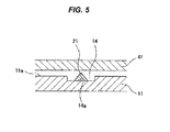
Fig. 5 , aseal mounting groove 14 for mounting agasket 21 is formed on the plane of theseparator 11 in conformity to arrangement of thegasket 21, and thegasket 21 is generally formed integrally in agroove bottom portion 14a of theseal mounting groove 14. - A cutting method is provided as a method of forming the
seal mounting groove 14 on the plane of theseparator 11 which is constructed by the metal plate. - However, the cutting method has a good processing precision, however, has a problem that the processing cost is high.
- Further, a pressing method is provided as a method of forming the
seal mounting groove 14 on the plane of theseparator 11 which is constructed by the metal plate, and the pressing method forms theseal mounting groove 14 on the plane of theseparator 11 on the basis of a strong pressure by apunch 31, as shown inFigs. 6A to 6C . Thepunch 31 is frequently provided as a part of a press mold. - However, since a leading
end portion 31 a of thepunch 31 is conventionally formed into a flat shape which is in parallel to thesurface 11 a of theseparator 11 as shown, the pressing pressure is dispersed. As a result, theseal mounting groove 14 having a predetermined depth can be formed only by applying an extremely great pressing pressure. - Further, since the metal which plastically deforms going with the formation of the
seal mounting groove 14 protrudes in shoulder portions in both right and left sides of the seal mounting groove 14 (the protruding portion is shown by reference numeral 15), there is a risk that a plane area of thepower generation area 12 which can normally function becomes narrower due to the protruding phenomenon. Further, in the case of carrying out a drawing process for crushing and flattening the protrudingportion 15, the protrudingportions 15 in both the right and left sides can be crushed and flattened only by applying the great pressing pressure. - Patent Document 1: Japanese Unexamined Patent Publication No.
2011-96545 Fig. 6 ) - The present invention is made by taking the above points into consideration, and an object of the present invention is to provide a processing method of a seal mounting groove in a metal plate, which can form the seal mounting groove with a small pressing pressure, whereby it is possible to respond to request for easily manufacturing and achieving a low cost, and can achieve a problem caused by a protruding phenomenon of a metal which plastically deforms going with formation of the seal mounting groove.
- In order to achieve the object, a processing method according to a first aspect of the present invention is a method of pressing a seal mounting groove by using a punch on a plane of a metal plate, wherein a leading end portion of the punch is formed into an inclined surface shape which is inclined in a punch width direction, and the seal mounting groove which inclines in a groove width direction in its groove bottom portion and is formed into an inclined surface shape is formed by pressing while using the punch.
- Further, a processing method according to a second aspect of the present invention is the processing method described in the first aspect mentioned above, wherein a cross sectional shape of the seal mounting groove is formed into a triangular cross sectional shape or an approximately triangular cross sectional shape which is provided with three sides constructed by an inclined surface shaped groove bottom portion, a groove side surface portion and a groove opening portion.
- Further, a processing method according to a third aspect of the present invention is the processing method described in the second aspect mentioned above, wherein the triangular shape satisfies a relationship L1 > L3 > L2, in which L1 is a length of the inclined surface shaped groove bottom portion, L2 is a length of the groove side surface portion, and L3 is a length of the groove opening portion.
- In the processing method of the present invention having the structure mentioned above, since the leading end portion of the punch is formed into the inclined surface shape which inclines in the punch width direction, the pressing process is started in advance in one end portion in the groove width direction of the seal mounting groove by using the punch, and an eating width at which the punch eats into the metal plate is expanded little by little according to the progress of the processing. Therefore, since the pressing pressure is concentrated partly, the seal mounting groove can be formed with the pressing pressure which is comparatively smaller than the conventional one.
- Further, in the case that the pressing process is carried out by using the punch which is formed into the inclined surface shape in its leading end portion, the metal plastically deforming going with the formation of the seal mounting groove protrudes only in the right or left one shoulder portion (the one where the punch leading end inclined surface goes backward) in place of both the right and left shoulder portions of the seal mounting groove. Therefore, it is possible to inhibit the plane area of the power generation area which can function normally from becoming narrower, by making the shoulder portion where the protruding phenomenon is not generated be included, for example, in the power generation area in the separator for the fuel battery. Further, since the drawing process is applied only to the one protruding portion in the case of carrying out the drawing process for crushing and flattening the protruding portion, it is possible to crush and flatten the protruding portion with the smaller pressing pressure than the conventional one.
- In the case that the pressing process is carried out by using the punch which is formed into the inclined surface shape in its leading end portion as described above, the seal mounting groove formed thereby is formed into the inclined surface shape which is inclined in its groove bottom portion in the groove width direction. As a result, for example, the gasket for the fuel battery is integrally formed in the inclined surface shaped groove bottom portion.
- As the cross sectional shape of the seal mounting groove having the inclined surface shaped groove bottom portion, the following aspects can be thought.
- (1) A quadrangular cross sectional shape or an approximately quadrangular cross sectional shape having four sides which are constructed by an inclined surface shaped groove bottom portion, a groove side surface portion having a deeper groove width, a groove side surface portion having a shallower groove depth and a groove opening portion.
- (2) A triangular cross sectional shape or an approximately triangular cross sectional shape having three sides which are constructed by an inclined surface shaped groove bottom portion, a groove side surface portion and a groove opening portion.
- The present invention includes both of the above items (1) and (2). However, in the case of (2), since the groove side surface portion is formed only in one in the groove width direction and is not formed in the other, the pressing process is finished in the other end portion without the punch eating into the metal plate. Therefore, since the eating amount of the punch into the metal plate is smaller according to the case (2) in comparison with the case (1), there is an advantage that the pressing process is finished for a short time.
- Since the inclined surface shaped groove bottom portion acts as the pressing surface compressing the gasket at the stack assembling time, an angle of incline thereof is preferably as small as possible. Therefore, from this point of view, the triangular shape preferably satisfies the relationship L1 > L3 > L2, in which L1 is the length of the inclined surface shaped groove bottom portion, L2 is the length of the groove side surface portion, and L3 is the length of the groove opening portion.
- The present invention achieves the following effects.
- More specifically, in the present invention, since the leading end portion of the punch is formed into the inclined surface shape which inclines in the punch width direction, as described above, the pressing process is started in advance in one end portion in the groove width direction of the seal mounting groove, and an eating width at which the punch eats into the metal plate is expanded little by little according to the progress of the processing. Therefore, since the pressing pressure is concentrated partly, the seal mounting groove can be formed with the pressing pressure which is comparatively smaller than the conventional one.
- Further, in the case that the pressing process is carried out by using the punch which is formed into the inclined surface shape in its leading end portion, the metal plastically deforming going with the formation of the seal mounting groove protrudes only in the one shoulder portion of the seal mounting groove, by carrying out the pressing process with using the punch which is formed into the inclined surface shape in its leading end portion. Therefore, it is possible to inhibit the area of the power generation area which functions normally from becoming narrower, by making the shoulder portion where the protruding phenomenon is not generated be included, for example, in the power generation area in the separator for the fuel battery. Further, since the drawing process is applied only to the one protruding portion in the case of carrying out the drawing process for crushing and flattening the protruding portion, it is possible to crush and flatten the protruding portion with the smaller pressing pressure than the conventional one.
- Therefore, according to the desired object of the present invention, it is possible to provide the processing method of the seal mounting groove in the metal plate, which can form the seal mounting groove with the small pressing pressure, whereby it is possible to respond to request for easily manufacturing and achieving the low cost, and can achieve the problem caused by the protruding phenomenon of the metal which plastically deforms going with formation of the seal mounting groove, on the basis of the above matters.
- Further, it is possible to shorten the pressing process time by forming the cross sectional shape of the seal mounting groove into the triangular cross sectional shape or the approximately triangular cross sectional shape having three sides which are constructed by the inclined surface shaped groove bottom portion, the groove side surface portion and the groove opening portion, and since the length of each of the sides of the triangular shape satisfies the relationship L1 > L3 > L2 mentioned above, it is possible to sufficiently compress the gasket even in the case that the groove bottom portion is formed into the inclined surface shape.
-
-
Fig. 1 is a view explaining steps of a processing method according to an embodiment of the present invention; -
Fig. 2 is a cross sectional view of a seal mounting groove which is formed by the processing method; -
Fig. 3 is a cross sectional view showing the other embodiment of the seal mounting groove; -
Fig. 4 is a plan view of a separator for a fuel battery as an example of a metal plate and a gasket provided in the separator; -
Fig. 5 is a cross sectional view of the separator, the gasket and a laminated part; and -
Fig. 6 is a view explaining steps of a processing method according to a prior art. - Next, a description will be given of embodiments according to the present invention with reference to the accompanying drawings.
- A processing method of a seal mounting groove according to the embodiment is a method for pressing a
seal mounting groove 14 on a plane of aseparator 11 for a fuel battery corresponding to a metal plate by using apunch 31, as shown inFig. 1 . As shown inFig. 1A , an inclined surface shapedseal mounting groove 14 in which agroove bottom portion 14a is inclined in a groove width direction is formed as shown inFig. 1C by preparing apunch 31 which is formed its leadingend portion 31a into an inclined surface shape inclining in a punch width direction, as thepunch 31, and pressing while using thepunch 31 as shown inFig. 1B . As post steps, agasket 21 constructed by a rubber-like elastic body is integrally formed in thegroove bottom portion 14a, and thegasket 21 is pinched and compressed between thegroove bottom portion 14a and a laminatedpart 41 at the stack assembling time. - A
leading end portion 31a of thepunch 31 is formed into an inclined surface shape which is linear over a whole width in a punch width direction. One end portion in theleading end portion 31 a is set to an acute angle shaped forward corner portion (an acute corner portion) 31 b, and the other end portion is set to an obtuse angle shaped rearward corner portion (an obtuse corner portion) 31 c. An amount of displacement in a pressing direction between the acute angle shapedforward corner portion 31 b and the obtuse angle shaped rearwardcorner portion 31 c is expressed by d on the drawing, and the pressing process by thepunch 31 is carried out over the displacement amount d. Therefore, the pressing process is finished at the same time when the obtuse angle shaped rearwardcorner portion 31 c reaches asurface 11 a of theseparator 11. In other words, the pressing process is set to be finished just before a press resistance of theseparator 11 to thepunch 31 reaches the maximum value. - Further, in the case that the pressing process is carried out by using the
punch 31 which is formed itsleading end portion 31a into the inclined surface shape as mentioned above, the metal plastically deforming going with the formation of theseal mounting groove 14 protrudes only in a shoulder portion in a shallower groove side of the seal mounting groove 14 (close to the obtuse angle shaped rearwardcorner portion 31 c in the punch leadingend portion 31a) (the protruding portion is shown by reference numeral 15). - Further, the
seal mounting groove 14 formed by the method is formed its cross sectional shape into a triangular cross sectional shape or an approximately triangular cross sectional shape having three sides which are constructed by an inclined surface shaped groovebottom portion 14a, a grooveside surface portion 14b and agroove opening portion 14c, as is shown inFig. 2 in an enlarged manner. The triangular shape is set to a right angled triangle since the grooveside surface portion 14b is vertical to thesurface 11 a of theseparator 11. Further, the triangular shape is set to satisfy a relationship L1 > L3 > L2 (expression e) in which L1 is a length of the inclined surface shaped groovebottom portion 14a, L2 is a length (a groove depth) of the grooveside surface portion 14a, and L3 is a length (a groove width) of the groove opening portion. L2 corresponds to the above d. - In the processing method having the structure mentioned above, since the
leading end portion 31 a of thepunch 31 is formed into the inclined surface shape which is inclined in the punch width direction, the pressing process is started in advance in one end portion in the groove width direction of theseal mounting groove 14, and an eating width at which thepunch 31 eats into theseparator 11 is expanded little by little according to the progress of the processing. Therefore, since the pressing pressure is concentrated partly, theseal mounting groove 14 can be formed with the pressing pressure which is comparatively smaller than the conventional one. - Further, since the pressing process is carried out by using the
punch 31 which is formed into the inclined surface shape in itsleading end portion 31 a, the metal plastically deforming going with the formation of theseal mounting groove 14 protrudes only in the shoulder portion close to the shallow groove side of theseal mounting groove 14. Therefore, it is possible to inhibit the plane area of the power generation area which can function normally from becoming narrower, by making the shoulder portion where the protruding phenomenon is not generated be included in the power generation area in theseparator 11. Further, since the drawing process is applied only to the one protrudingportion 15 in the case of carrying out the drawing process for crushing and flattening the protrudingportion 15, it is possible to crush and flatten the protrudingportion 15 with the smaller pressing pressure than the conventional one. - Further, it is possible to shorten the pressing process time by forming the cross sectional shape of the
seal mounting groove 14 into the triangular cross sectional shape or the approximately triangular cross sectional shape having three sides which are constructed by the inclined surface shaped groovebottom portion 14a, the grooveside surface portion 14b and thegroove opening portion 14c. Further, since the length of each of the sides of the triangular shape satisfies the relationship of the expression (e) mentioned above, it is possible to sufficiently compress thegasket 21 even in the case that thegroove bottom portion 14a is formed into the inclined surface shape. - As described above, the cross sectional shape of the
seal mounting groove 14 may be formed, for example, into a quadrangular cross sectional shape or an approximately quadrangular cross sectional shape having four sides which are constructed by an inclined surface shaped groovebottom portion 14a, a grooveside surface portion 14b having a deeper groove depth, a grooveside surface portion 14d having a shallower groove depth and agroove opening portion 14c, as shown inFig. 3 . In this case, the groove depth becomes deeper in comparison withFig. 2 , however, it is possible to increase a volumetric capacity of theseal mounting groove 14. Further, inFig. 1C , thegasket 21 is formed into the triangular cross sectional shape, however, the cross sectional shape of thegasket 21 is not particularly limited in the present invention, for example, may be formed into a chevron cross sectional shape. Further, thegasket 21 may be integrally formed in thegroove bottom portion 14a of theseal mounting groove 14, and may be bonded to thegroove bottom portion 14a after being independently formed. -
- 11
- separator (metal plate)
- 11a
- surface
- 12
- power generation area
- 13
- manifold hole
- 14
- seal mounting groove
- 14a
- groove bottom portion
- 14b, 14d
- groove side surface portion
- 14c
- groove opening portion
- 15
- protruding portion
- 21
- gasket
- 31
- punch
- 31a
- leading end portion
- 31b
- forward corner portion
- 31c
- rearward corner portion
- 41
- laminated part
Claims (3)
- A processing method of a seal mounting groove, the method pressing the seal mounting groove by using a punch on a plane of a metal plate,
wherein a leading end portion of said punch is formed into an inclined surface shape which is inclined in a punch width direction, and the seal mounting groove which inclines in a groove width direction in its groove bottom portion and is formed into an inclined surface shape is formed by pressing while using said punch. - The processing method of the seal mounting groove according to claim 1, wherein a cross sectional shape of the seal mounting groove is formed into a triangular cross sectional shape or an approximately triangular cross sectional shape which is provided with three sides constructed by an inclined surface shaped groove bottom portion, a groove side surface portion and a groove opening portion.
- The processing method of the seal mounting groove according to claim 2, wherein said triangular shape satisfies a relationship L1 > L3 > L2, in which L1 is a length of the inclined surface shaped groove bottom portion, L2 is a length of the groove side surface portion, and L3 is a length of the groove opening portion.
Applications Claiming Priority (2)
| Application Number | Priority Date | Filing Date | Title |
|---|---|---|---|
| JP2012238981A JP6125194B2 (en) | 2012-10-30 | 2012-10-30 | Method for machining seal mounting groove in metal plate |
| PCT/JP2013/077201 WO2014069171A1 (en) | 2012-10-30 | 2013-10-07 | Method for machining seal-mounting groove in metal plate |
Publications (3)
| Publication Number | Publication Date |
|---|---|
| EP2915605A1 true EP2915605A1 (en) | 2015-09-09 |
| EP2915605A4 EP2915605A4 (en) | 2016-03-09 |
| EP2915605B1 EP2915605B1 (en) | 2020-09-23 |
Family
ID=50627087
Family Applications (1)
| Application Number | Title | Priority Date | Filing Date |
|---|---|---|---|
| EP13851419.5A Active EP2915605B1 (en) | 2012-10-30 | 2013-10-07 | Processing method of a seal mounting groove in a metal plate |
Country Status (5)
| Country | Link |
|---|---|
| US (1) | US9592617B2 (en) |
| EP (1) | EP2915605B1 (en) |
| JP (1) | JP6125194B2 (en) |
| CA (1) | CA2889305C (en) |
| WO (1) | WO2014069171A1 (en) |
Families Citing this family (2)
| Publication number | Priority date | Publication date | Assignee | Title |
|---|---|---|---|---|
| JP6363433B2 (en) * | 2014-09-02 | 2018-07-25 | Nok株式会社 | Gasket for laminated member |
| CN114872124B (en) * | 2022-04-15 | 2023-09-29 | 湖北平安电工科技股份公司 | Milling machine for mica plate machine tool machining and mica plate forming method |
Family Cites Families (16)
| Publication number | Priority date | Publication date | Assignee | Title |
|---|---|---|---|---|
| US2013333A (en) * | 1933-03-17 | 1935-09-03 | Graton & Knight Company | Method of producing oil seals |
| US3866456A (en) * | 1972-01-14 | 1975-02-18 | Torrington Co | Felting needle |
| US4300381A (en) * | 1980-08-15 | 1981-11-17 | Riken Corporation | Method for producing insert for diesel engine combustion chamber |
| JPS5747531A (en) * | 1980-09-04 | 1982-03-18 | Senjiyu Kinzoku Kogyo Kk | Bearing plate and its grooving method |
| US4558585A (en) * | 1984-03-19 | 1985-12-17 | The United States Of America As Represented By The Administrator Of The National Aeronautics And Space Administration | Ultrasonic angle beam standard reflector |
| JPH05248542A (en) * | 1991-12-30 | 1993-09-24 | Japan Atom Energy Res Inst | Vacuum sealing structure using metal gasket, vacuum sealing method, metal gasket for vacuum sealing, and vacuum flange for metal gasket |
| JPH0732059A (en) | 1993-07-16 | 1995-02-03 | Mazda Motor Corp | Press processing method |
| JPH10256431A (en) | 1997-03-06 | 1998-09-25 | Sony Corp | Semiconductor device and manufacturing method thereof |
| DE19755104C2 (en) | 1997-12-11 | 2000-11-02 | Freudenberg Carl Fa | Method of making a ring |
| JP2001210283A (en) * | 2000-01-31 | 2001-08-03 | Asahi-Seiki Mfg Co Ltd | Groove processing method for battery can bottom |
| JP2002203581A (en) * | 2000-12-28 | 2002-07-19 | Toyota Motor Corp | Gas seal structure of high temperature fuel cell |
| EP1557228A4 (en) * | 2002-07-09 | 2005-10-12 | Seiko Epson Corp | FINE FORGING PROCESS, METHOD FOR MANUFACTURING LIQUID INJECTION HEAD, AND LIQUID INJECTION HEAD |
| US7269989B2 (en) * | 2004-03-24 | 2007-09-18 | Siemens Vdo Automotive Corporation | Method of using a tool to form angled orifices in a metering orifice disc |
| JP5234257B2 (en) | 2008-05-15 | 2013-07-10 | Nok株式会社 | Fuel cell seal structure |
| JP5440775B2 (en) | 2009-10-30 | 2014-03-12 | Nok株式会社 | Fuel cell component and manufacturing method thereof |
| US8683905B2 (en) * | 2011-12-28 | 2014-04-01 | Unison Industries, Llc | Methods of skiving metal and forming a fin in a heat exchanger |
-
2012
- 2012-10-30 JP JP2012238981A patent/JP6125194B2/en not_active Expired - Fee Related
-
2013
- 2013-10-07 EP EP13851419.5A patent/EP2915605B1/en active Active
- 2013-10-07 US US14/437,991 patent/US9592617B2/en not_active Expired - Fee Related
- 2013-10-07 CA CA2889305A patent/CA2889305C/en not_active Expired - Fee Related
- 2013-10-07 WO PCT/JP2013/077201 patent/WO2014069171A1/en not_active Ceased
Also Published As
| Publication number | Publication date |
|---|---|
| JP2014087821A (en) | 2014-05-15 |
| US20150290824A1 (en) | 2015-10-15 |
| US9592617B2 (en) | 2017-03-14 |
| CA2889305C (en) | 2020-05-12 |
| WO2014069171A1 (en) | 2014-05-08 |
| EP2915605B1 (en) | 2020-09-23 |
| CA2889305A1 (en) | 2014-05-08 |
| JP6125194B2 (en) | 2017-05-10 |
| EP2915605A4 (en) | 2016-03-09 |
Similar Documents
| Publication | Publication Date | Title |
|---|---|---|
| US8070536B2 (en) | Crimp terminal, terminal-provided wire, and manufacturing method thereof | |
| CN103260785B (en) | Punch die of a punch press, die for deepening cutting, and method of forming long holes in a plate | |
| US8499451B2 (en) | Method for assembling heat sink | |
| JP2013126673A (en) | Thin plate burring method and thin plate female screw-forming method | |
| JP2017018990A (en) | Metal surface roughening apparatus and surface roughening method | |
| CA2889305C (en) | Method for machining seal-mounting groove in metal plate | |
| US7677430B2 (en) | Cold-pressure welding method and metal product welded by the method | |
| JP5713509B2 (en) | Method of internal splitting of end cross section of metal plate or metal rod, method of manufacturing metal container and metal tube by the internal splitting method, and method of joining metal parts | |
| CN118808449A (en) | A lithium battery top cover sheet and its explosion-proof valve installation hole forming process | |
| US20110027605A1 (en) | Metal sheet member having high plastic bonding strength | |
| KR20120004959A (en) | Electrolytic capacitors and manufacturing method | |
| JP5578315B2 (en) | PCB terminal | |
| EP0602937B1 (en) | Process for making press-in connection type contact | |
| JP3777435B2 (en) | Manufacturing method of motor core and motor core | |
| JP4198675B2 (en) | Composite molded article and manufacturing method thereof | |
| JP2006043719A (en) | Element for continuously variable transmission and method for manufacturing the same | |
| US10994323B2 (en) | Method of manufacturing washer and washer | |
| CN116190906A (en) | Power battery case and method for manufacturing same | |
| WO2013069175A1 (en) | Cut-out sintered ceramic sheet and method of manufacturing the same | |
| US20240186869A1 (en) | Method of manufacturing motor core | |
| JP2014217877A (en) | Laminate and laminate production method | |
| US11247258B2 (en) | Method for manufacturing separator | |
| CN206981561U (en) | Auto panel diel | |
| CN121715469A (en) | Blanking process for realizing burr-free full-bright surface of cut surface | |
| JP3922465B1 (en) | Mold for processing base plate, method for manufacturing processed plate, and method for manufacturing product plate |
Legal Events
| Date | Code | Title | Description |
|---|---|---|---|
| PUAI | Public reference made under article 153(3) epc to a published international application that has entered the european phase |
Free format text: ORIGINAL CODE: 0009012 |
|
| 17P | Request for examination filed |
Effective date: 20150504 |
|
| AK | Designated contracting states |
Kind code of ref document: A1 Designated state(s): AL AT BE BG CH CY CZ DE DK EE ES FI FR GB GR HR HU IE IS IT LI LT LU LV MC MK MT NL NO PL PT RO RS SE SI SK SM TR |
|
| AX | Request for extension of the european patent |
Extension state: BA ME |
|
| DAX | Request for extension of the european patent (deleted) | ||
| RA4 | Supplementary search report drawn up and despatched (corrected) |
Effective date: 20160204 |
|
| RIC1 | Information provided on ipc code assigned before grant |
Ipc: B21D 17/02 20060101AFI20160129BHEP Ipc: F16J 15/06 20060101ALI20160129BHEP Ipc: B21D 22/02 20060101ALI20160129BHEP |
|
| STAA | Information on the status of an ep patent application or granted ep patent |
Free format text: STATUS: EXAMINATION IS IN PROGRESS |
|
| 17Q | First examination report despatched |
Effective date: 20181121 |
|
| GRAP | Despatch of communication of intention to grant a patent |
Free format text: ORIGINAL CODE: EPIDOSNIGR1 |
|
| STAA | Information on the status of an ep patent application or granted ep patent |
Free format text: STATUS: GRANT OF PATENT IS INTENDED |
|
| INTG | Intention to grant announced |
Effective date: 20200428 |
|
| GRAS | Grant fee paid |
Free format text: ORIGINAL CODE: EPIDOSNIGR3 |
|
| GRAA | (expected) grant |
Free format text: ORIGINAL CODE: 0009210 |
|
| STAA | Information on the status of an ep patent application or granted ep patent |
Free format text: STATUS: THE PATENT HAS BEEN GRANTED |
|
| AK | Designated contracting states |
Kind code of ref document: B1 Designated state(s): AL AT BE BG CH CY CZ DE DK EE ES FI FR GB GR HR HU IE IS IT LI LT LU LV MC MK MT NL NO PL PT RO RS SE SI SK SM TR |
|
| REG | Reference to a national code |
Ref country code: GB Ref legal event code: FG4D |
|
| REG | Reference to a national code |
Ref country code: CH Ref legal event code: EP |
|
| REG | Reference to a national code |
Ref country code: DE Ref legal event code: R096 Ref document number: 602013072820 Country of ref document: DE |
|
| REG | Reference to a national code |
Ref country code: IE Ref legal event code: FG4D |
|
| REG | Reference to a national code |
Ref country code: AT Ref legal event code: REF Ref document number: 1315863 Country of ref document: AT Kind code of ref document: T Effective date: 20201015 |
|
| PG25 | Lapsed in a contracting state [announced via postgrant information from national office to epo] |
Ref country code: HR Free format text: LAPSE BECAUSE OF FAILURE TO SUBMIT A TRANSLATION OF THE DESCRIPTION OR TO PAY THE FEE WITHIN THE PRESCRIBED TIME-LIMIT Effective date: 20200923 Ref country code: FI Free format text: LAPSE BECAUSE OF FAILURE TO SUBMIT A TRANSLATION OF THE DESCRIPTION OR TO PAY THE FEE WITHIN THE PRESCRIBED TIME-LIMIT Effective date: 20200923 Ref country code: NO Free format text: LAPSE BECAUSE OF FAILURE TO SUBMIT A TRANSLATION OF THE DESCRIPTION OR TO PAY THE FEE WITHIN THE PRESCRIBED TIME-LIMIT Effective date: 20201223 Ref country code: BG Free format text: LAPSE BECAUSE OF FAILURE TO SUBMIT A TRANSLATION OF THE DESCRIPTION OR TO PAY THE FEE WITHIN THE PRESCRIBED TIME-LIMIT Effective date: 20201223 Ref country code: GR Free format text: LAPSE BECAUSE OF FAILURE TO SUBMIT A TRANSLATION OF THE DESCRIPTION OR TO PAY THE FEE WITHIN THE PRESCRIBED TIME-LIMIT Effective date: 20201224 Ref country code: SE Free format text: LAPSE BECAUSE OF FAILURE TO SUBMIT A TRANSLATION OF THE DESCRIPTION OR TO PAY THE FEE WITHIN THE PRESCRIBED TIME-LIMIT Effective date: 20200923 |
|
| REG | Reference to a national code |
Ref country code: AT Ref legal event code: MK05 Ref document number: 1315863 Country of ref document: AT Kind code of ref document: T Effective date: 20200923 |
|
| PG25 | Lapsed in a contracting state [announced via postgrant information from national office to epo] |
Ref country code: RS Free format text: LAPSE BECAUSE OF FAILURE TO SUBMIT A TRANSLATION OF THE DESCRIPTION OR TO PAY THE FEE WITHIN THE PRESCRIBED TIME-LIMIT Effective date: 20200923 Ref country code: LV Free format text: LAPSE BECAUSE OF FAILURE TO SUBMIT A TRANSLATION OF THE DESCRIPTION OR TO PAY THE FEE WITHIN THE PRESCRIBED TIME-LIMIT Effective date: 20200923 |
|
| REG | Reference to a national code |
Ref country code: NL Ref legal event code: MP Effective date: 20200923 |
|
| REG | Reference to a national code |
Ref country code: LT Ref legal event code: MG4D |
|
| PG25 | Lapsed in a contracting state [announced via postgrant information from national office to epo] |
Ref country code: RO Free format text: LAPSE BECAUSE OF FAILURE TO SUBMIT A TRANSLATION OF THE DESCRIPTION OR TO PAY THE FEE WITHIN THE PRESCRIBED TIME-LIMIT Effective date: 20200923 Ref country code: SM Free format text: LAPSE BECAUSE OF FAILURE TO SUBMIT A TRANSLATION OF THE DESCRIPTION OR TO PAY THE FEE WITHIN THE PRESCRIBED TIME-LIMIT Effective date: 20200923 Ref country code: PT Free format text: LAPSE BECAUSE OF FAILURE TO SUBMIT A TRANSLATION OF THE DESCRIPTION OR TO PAY THE FEE WITHIN THE PRESCRIBED TIME-LIMIT Effective date: 20210125 Ref country code: LT Free format text: LAPSE BECAUSE OF FAILURE TO SUBMIT A TRANSLATION OF THE DESCRIPTION OR TO PAY THE FEE WITHIN THE PRESCRIBED TIME-LIMIT Effective date: 20200923 Ref country code: NL Free format text: LAPSE BECAUSE OF FAILURE TO SUBMIT A TRANSLATION OF THE DESCRIPTION OR TO PAY THE FEE WITHIN THE PRESCRIBED TIME-LIMIT Effective date: 20200923 Ref country code: CZ Free format text: LAPSE BECAUSE OF FAILURE TO SUBMIT A TRANSLATION OF THE DESCRIPTION OR TO PAY THE FEE WITHIN THE PRESCRIBED TIME-LIMIT Effective date: 20200923 Ref country code: EE Free format text: LAPSE BECAUSE OF FAILURE TO SUBMIT A TRANSLATION OF THE DESCRIPTION OR TO PAY THE FEE WITHIN THE PRESCRIBED TIME-LIMIT Effective date: 20200923 |
|
| PG25 | Lapsed in a contracting state [announced via postgrant information from national office to epo] |
Ref country code: IS Free format text: LAPSE BECAUSE OF FAILURE TO SUBMIT A TRANSLATION OF THE DESCRIPTION OR TO PAY THE FEE WITHIN THE PRESCRIBED TIME-LIMIT Effective date: 20210123 Ref country code: PL Free format text: LAPSE BECAUSE OF FAILURE TO SUBMIT A TRANSLATION OF THE DESCRIPTION OR TO PAY THE FEE WITHIN THE PRESCRIBED TIME-LIMIT Effective date: 20200923 Ref country code: ES Free format text: LAPSE BECAUSE OF FAILURE TO SUBMIT A TRANSLATION OF THE DESCRIPTION OR TO PAY THE FEE WITHIN THE PRESCRIBED TIME-LIMIT Effective date: 20200923 Ref country code: AT Free format text: LAPSE BECAUSE OF FAILURE TO SUBMIT A TRANSLATION OF THE DESCRIPTION OR TO PAY THE FEE WITHIN THE PRESCRIBED TIME-LIMIT Effective date: 20200923 Ref country code: AL Free format text: LAPSE BECAUSE OF FAILURE TO SUBMIT A TRANSLATION OF THE DESCRIPTION OR TO PAY THE FEE WITHIN THE PRESCRIBED TIME-LIMIT Effective date: 20200923 |
|
| REG | Reference to a national code |
Ref country code: CH Ref legal event code: PL |
|
| REG | Reference to a national code |
Ref country code: DE Ref legal event code: R097 Ref document number: 602013072820 Country of ref document: DE |
|
| PG25 | Lapsed in a contracting state [announced via postgrant information from national office to epo] |
Ref country code: MC Free format text: LAPSE BECAUSE OF FAILURE TO SUBMIT A TRANSLATION OF THE DESCRIPTION OR TO PAY THE FEE WITHIN THE PRESCRIBED TIME-LIMIT Effective date: 20200923 Ref country code: SK Free format text: LAPSE BECAUSE OF FAILURE TO SUBMIT A TRANSLATION OF THE DESCRIPTION OR TO PAY THE FEE WITHIN THE PRESCRIBED TIME-LIMIT Effective date: 20200923 Ref country code: LU Free format text: LAPSE BECAUSE OF NON-PAYMENT OF DUE FEES Effective date: 20201007 |
|
| REG | Reference to a national code |
Ref country code: BE Ref legal event code: MM Effective date: 20201031 |
|
| PLBE | No opposition filed within time limit |
Free format text: ORIGINAL CODE: 0009261 |
|
| STAA | Information on the status of an ep patent application or granted ep patent |
Free format text: STATUS: NO OPPOSITION FILED WITHIN TIME LIMIT |
|
| GBPC | Gb: european patent ceased through non-payment of renewal fee |
Effective date: 20201223 |
|
| PG25 | Lapsed in a contracting state [announced via postgrant information from national office to epo] |
Ref country code: BE Free format text: LAPSE BECAUSE OF NON-PAYMENT OF DUE FEES Effective date: 20201031 Ref country code: CH Free format text: LAPSE BECAUSE OF NON-PAYMENT OF DUE FEES Effective date: 20201031 Ref country code: DK Free format text: LAPSE BECAUSE OF FAILURE TO SUBMIT A TRANSLATION OF THE DESCRIPTION OR TO PAY THE FEE WITHIN THE PRESCRIBED TIME-LIMIT Effective date: 20200923 Ref country code: SI Free format text: LAPSE BECAUSE OF FAILURE TO SUBMIT A TRANSLATION OF THE DESCRIPTION OR TO PAY THE FEE WITHIN THE PRESCRIBED TIME-LIMIT Effective date: 20200923 Ref country code: LI Free format text: LAPSE BECAUSE OF NON-PAYMENT OF DUE FEES Effective date: 20201031 |
|
| 26N | No opposition filed |
Effective date: 20210624 |
|
| PG25 | Lapsed in a contracting state [announced via postgrant information from national office to epo] |
Ref country code: FR Free format text: LAPSE BECAUSE OF NON-PAYMENT OF DUE FEES Effective date: 20201123 Ref country code: IT Free format text: LAPSE BECAUSE OF FAILURE TO SUBMIT A TRANSLATION OF THE DESCRIPTION OR TO PAY THE FEE WITHIN THE PRESCRIBED TIME-LIMIT Effective date: 20200923 Ref country code: IE Free format text: LAPSE BECAUSE OF NON-PAYMENT OF DUE FEES Effective date: 20201007 |
|
| PG25 | Lapsed in a contracting state [announced via postgrant information from national office to epo] |
Ref country code: GB Free format text: LAPSE BECAUSE OF NON-PAYMENT OF DUE FEES Effective date: 20201223 |
|
| PGFP | Annual fee paid to national office [announced via postgrant information from national office to epo] |
Ref country code: DE Payment date: 20210831 Year of fee payment: 9 |
|
| PG25 | Lapsed in a contracting state [announced via postgrant information from national office to epo] |
Ref country code: IS Free format text: LAPSE BECAUSE OF FAILURE TO SUBMIT A TRANSLATION OF THE DESCRIPTION OR TO PAY THE FEE WITHIN THE PRESCRIBED TIME-LIMIT Effective date: 20210123 Ref country code: TR Free format text: LAPSE BECAUSE OF FAILURE TO SUBMIT A TRANSLATION OF THE DESCRIPTION OR TO PAY THE FEE WITHIN THE PRESCRIBED TIME-LIMIT Effective date: 20200923 Ref country code: MT Free format text: LAPSE BECAUSE OF FAILURE TO SUBMIT A TRANSLATION OF THE DESCRIPTION OR TO PAY THE FEE WITHIN THE PRESCRIBED TIME-LIMIT Effective date: 20200923 Ref country code: CY Free format text: LAPSE BECAUSE OF FAILURE TO SUBMIT A TRANSLATION OF THE DESCRIPTION OR TO PAY THE FEE WITHIN THE PRESCRIBED TIME-LIMIT Effective date: 20200923 |
|
| PG25 | Lapsed in a contracting state [announced via postgrant information from national office to epo] |
Ref country code: MK Free format text: LAPSE BECAUSE OF FAILURE TO SUBMIT A TRANSLATION OF THE DESCRIPTION OR TO PAY THE FEE WITHIN THE PRESCRIBED TIME-LIMIT Effective date: 20200923 |
|
| REG | Reference to a national code |
Ref country code: DE Ref legal event code: R119 Ref document number: 602013072820 Country of ref document: DE |
|
| PG25 | Lapsed in a contracting state [announced via postgrant information from national office to epo] |
Ref country code: DE Free format text: LAPSE BECAUSE OF NON-PAYMENT OF DUE FEES Effective date: 20230503 |