EP2915491A1 - Method, apparatus, and system for outputting information of blood flow included in region of interest based on selection information - Google Patents
Method, apparatus, and system for outputting information of blood flow included in region of interest based on selection information Download PDFInfo
- Publication number
- EP2915491A1 EP2915491A1 EP14171251.3A EP14171251A EP2915491A1 EP 2915491 A1 EP2915491 A1 EP 2915491A1 EP 14171251 A EP14171251 A EP 14171251A EP 2915491 A1 EP2915491 A1 EP 2915491A1
- Authority
- EP
- European Patent Office
- Prior art keywords
- ultrasound image
- blood flow
- image processing
- roi
- blood flows
- Prior art date
- Legal status (The legal status is an assumption and is not a legal conclusion. Google has not performed a legal analysis and makes no representation as to the accuracy of the status listed.)
- Granted
Links
Images


Classifications
-
- G—PHYSICS
- G06—COMPUTING OR CALCULATING; COUNTING
- G06V—IMAGE OR VIDEO RECOGNITION OR UNDERSTANDING
- G06V20/00—Scenes; Scene-specific elements
- G06V20/60—Type of objects
- G06V20/69—Microscopic objects, e.g. biological cells or cellular parts
- G06V20/695—Preprocessing, e.g. image segmentation
-
- A—HUMAN NECESSITIES
- A61—MEDICAL OR VETERINARY SCIENCE; HYGIENE
- A61B—DIAGNOSIS; SURGERY; IDENTIFICATION
- A61B8/00—Diagnosis using ultrasonic, sonic or infrasonic waves
- A61B8/06—Measuring blood flow
-
- A—HUMAN NECESSITIES
- A61—MEDICAL OR VETERINARY SCIENCE; HYGIENE
- A61B—DIAGNOSIS; SURGERY; IDENTIFICATION
- A61B8/00—Diagnosis using ultrasonic, sonic or infrasonic waves
- A61B8/46—Ultrasonic, sonic or infrasonic diagnostic devices with special arrangements for interfacing with the operator or the patient
- A61B8/461—Displaying means of special interest
- A61B8/465—Displaying means of special interest adapted to display user selection data, e.g. icons or menus
-
- A—HUMAN NECESSITIES
- A61—MEDICAL OR VETERINARY SCIENCE; HYGIENE
- A61B—DIAGNOSIS; SURGERY; IDENTIFICATION
- A61B8/00—Diagnosis using ultrasonic, sonic or infrasonic waves
- A61B8/46—Ultrasonic, sonic or infrasonic diagnostic devices with special arrangements for interfacing with the operator or the patient
- A61B8/467—Ultrasonic, sonic or infrasonic diagnostic devices with special arrangements for interfacing with the operator or the patient characterised by special input means
- A61B8/469—Ultrasonic, sonic or infrasonic diagnostic devices with special arrangements for interfacing with the operator or the patient characterised by special input means for selection of a region of interest
-
- A—HUMAN NECESSITIES
- A61—MEDICAL OR VETERINARY SCIENCE; HYGIENE
- A61B—DIAGNOSIS; SURGERY; IDENTIFICATION
- A61B8/00—Diagnosis using ultrasonic, sonic or infrasonic waves
- A61B8/48—Diagnostic techniques
- A61B8/488—Diagnostic techniques involving Doppler signals
-
- A—HUMAN NECESSITIES
- A61—MEDICAL OR VETERINARY SCIENCE; HYGIENE
- A61B—DIAGNOSIS; SURGERY; IDENTIFICATION
- A61B8/00—Diagnosis using ultrasonic, sonic or infrasonic waves
- A61B8/52—Devices using data or image processing specially adapted for diagnosis using ultrasonic, sonic or infrasonic waves
- A61B8/5215—Devices using data or image processing specially adapted for diagnosis using ultrasonic, sonic or infrasonic waves involving processing of medical diagnostic data
- A61B8/5223—Devices using data or image processing specially adapted for diagnosis using ultrasonic, sonic or infrasonic waves involving processing of medical diagnostic data for extracting a diagnostic or physiological parameter from medical diagnostic data
-
- G—PHYSICS
- G16—INFORMATION AND COMMUNICATION TECHNOLOGY [ICT] SPECIALLY ADAPTED FOR SPECIFIC APPLICATION FIELDS
- G16H—HEALTHCARE INFORMATICS, i.e. INFORMATION AND COMMUNICATION TECHNOLOGY [ICT] SPECIALLY ADAPTED FOR THE HANDLING OR PROCESSING OF MEDICAL OR HEALTHCARE DATA
- G16H50/00—ICT specially adapted for medical diagnosis, medical simulation or medical data mining; ICT specially adapted for detecting, monitoring or modelling epidemics or pandemics
- G16H50/30—ICT specially adapted for medical diagnosis, medical simulation or medical data mining; ICT specially adapted for detecting, monitoring or modelling epidemics or pandemics for calculating health indices; for individual health risk assessment
-
- A—HUMAN NECESSITIES
- A61—MEDICAL OR VETERINARY SCIENCE; HYGIENE
- A61B—DIAGNOSIS; SURGERY; IDENTIFICATION
- A61B8/00—Diagnosis using ultrasonic, sonic or infrasonic waves
- A61B8/46—Ultrasonic, sonic or infrasonic diagnostic devices with special arrangements for interfacing with the operator or the patient
- A61B8/467—Ultrasonic, sonic or infrasonic diagnostic devices with special arrangements for interfacing with the operator or the patient characterised by special input means
- A61B8/468—Ultrasonic, sonic or infrasonic diagnostic devices with special arrangements for interfacing with the operator or the patient characterised by special input means allowing annotation or message recording
-
- A—HUMAN NECESSITIES
- A61—MEDICAL OR VETERINARY SCIENCE; HYGIENE
- A61B—DIAGNOSIS; SURGERY; IDENTIFICATION
- A61B8/00—Diagnosis using ultrasonic, sonic or infrasonic waves
- A61B8/52—Devices using data or image processing specially adapted for diagnosis using ultrasonic, sonic or infrasonic waves
- A61B8/5292—Devices using data or image processing specially adapted for diagnosis using ultrasonic, sonic or infrasonic waves using additional data, e.g. patient information, image labeling, acquisition parameters
-
- G—PHYSICS
- G06—COMPUTING OR CALCULATING; COUNTING
- G06T—IMAGE DATA PROCESSING OR GENERATION, IN GENERAL
- G06T2207/00—Indexing scheme for image analysis or image enhancement
- G06T2207/10—Image acquisition modality
- G06T2207/10132—Ultrasound image
-
- G—PHYSICS
- G06—COMPUTING OR CALCULATING; COUNTING
- G06T—IMAGE DATA PROCESSING OR GENERATION, IN GENERAL
- G06T2207/00—Indexing scheme for image analysis or image enhancement
- G06T2207/30—Subject of image; Context of image processing
- G06T2207/30004—Biomedical image processing
- G06T2207/30101—Blood vessel; Artery; Vein; Vascular
- G06T2207/30104—Vascular flow; Blood flow; Perfusion
Definitions
- One or more embodiments of the present invention relate to a method, apparatus, and system for outputting information of blood flow included in a region of interest (ROI) based on selection information.
- ROI region of interest
- a Doppler image generating apparatus irradiates an ultrasound wave onto an ROI, and measures a Doppler shift frequency of an echo signal reflected from blood flow included in the ROI, thereby detecting a distribution of blood flow in real time.
- the Doppler image generating apparatus automatically finds a position of blood flow included in an ROI to dispose a color box or a sample volume (SV) at the position, estimates an angle of the blood flow in which the color box or the sample volume is disposed, and adjusts a slope of the color box or an angle of the sample volume.
- SV sample volume
- the Doppler image generating apparatus automatically disposes the color box or the sample volume in blood flow where an amount of blood flow is the largest, and for this reason, it is difficult to acquire information of blood flow desired by a user.
- One or more embodiments of the present invention include a method, apparatus, and system for outputting information of blood flow included in an ROI based on selection information.
- One or more embodiments of the present invention include a non-transitory computer-readable storage medium storing a program for executing the method in a computer.
- an ultrasound image processing method includes: generating an ultrasound image indicating a region of interest (ROI) by using echo signals which corresponds to ultrasound waves irradiated onto the ROI; sequentially setting respective indexes in a plurality of blood flows included in the ROI detected based on the ultrasound image; determining blood flow corresponding to a selected index, based on an external signal for selecting one of the set indexes; and displaying information corresponding to the determined blood flow.
- ROI region of interest
- a non-transitory computer-readable storage medium storing a program for executing the ultrasound image processing method in a computer.
- an ultrasound image processing apparatus includes: a generation unit that generates an ultrasound image indicating a region of interest (ROI) by using echo signals which corresponds to ultrasound waves irradiated onto the ROI; a setting unit that sequentially sets respective indexes in a plurality of blood flows included in the ROI detected based on the ultrasound image; a determination unit that determines blood flow corresponding to a selected index, based on an external signal for selecting one of the set indexes; and a display unit that displays information corresponding to the determined blood flow.
- ROI region of interest
- an ultrasound diagnostic system includes: a probe that irradiates ultrasound waves onto a region of interest (ROI) included in an object, and receives echo signals which corresponds to an ultrasound wave; and an image processing apparatus that generates an ultrasound image indicating the ROI by using the echo signal, sequentially sets respective indexes in a plurality of blood flows included in the ROI detected based on the ultrasound image, determines blood flow corresponding to a selected index, based on an external signal for selecting one of the set indexes, and displays information corresponding to the determined blood flow.
- ROI region of interest
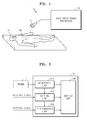
- FIG. 1 is a configuration diagram illustrating an example of an ultrasound diagnostic system 1 according to an embodiment.
- the ultrasound diagnostic system 1 includes a probe 10 and an image processing apparatus 20.
- the ultrasound diagnostic system 1 of FIG. 1 is illustrated as including only elements associated with the present embodiment. Therefore, it may be understood by those skilled in the art that the ultrasound diagnostic system 1 may further include general-use elements in addition to the elements of FIG. 1 .
- the probe 10 irradiates ultrasound waves onto an ROI 40 included in an object 30, and receives echo signals corresponding to the irradiated ultrasound wave. In other words, the probe 10 irradiates the ultrasound waves onto the ROI 40.
- the probe 10 receives the echo signals that are signals reflected from each of tissues included in the ROI 40.
- the probe 10 transmits the echo signals to a generation unit 210 included in the image processing apparatus 20.
- an ultrasound signal generating unit (not shown) of the image processing apparatus 20 may perform a transmission beamforming operation in consideration of a position and size of the ROI 40 to generate ultrasound waves which are irradiated by the probe 10.
- a detailed method of generating ultrasound waves irradiated by the probe 10 is obvious to one of ordinary skill in the art, and thus, its detailed description is not provided.
- the ultrasound waves are partially reflected from layers between a plurality of tissues.
- the ultrasound waves may be reflected from parts (for example, blood cells of blood plasma, and small tissues of organs) in which a density is changed in the object 30.
- Reflected signals vibrate the transducers (not shown), which output electrical pulses based on the vibrations.
- the probe 10 transmits the electrical pulses to the generation unit 210.
- the object 30 denotes a target of which an image is to be generated, and for example, may be a patient.
- the present embodiment is not limited thereto.
- the ROI 40 denotes an internal certain region of the object 30 of which an image is generated, and for example, may be a region including a plurality of blood flows.
- the present embodiment is not limited thereto.
- the image processing apparatus 20 generates an ultrasound image indicating the ROI 40 by using the echo signals transmitted from the probe 10.
- the image processing apparatus 20 detects a plurality of blood flows included in the ROI 40 on the basis of the generated ultrasound image, and sequentially sets respective indexes in the detected blood flows.
- the image processing apparatus 20 determines blood flow corresponding to a selected index on the basis of an external signal for selecting one of the indexes.
- the external signal may be a signal which is input by a user by using an input device (not shown), which includes an input device, such as a knob button, a trackball, a mouse, a keyboard, or a touch screen, and a software module for driving the same.
- the image processing apparatus 20 displays information corresponding to the determined blood flow.
- FIG. 2 is a block diagram illustrating an example of the image processing apparatus 20 according to an embodiment.
- the image processing apparatus 20 includes a generation unit 210, a setting unit 220, a determination unit 230, and a display unit 240.
- the image processing apparatus 20 of FIG. 2 is illustrated as including only elements associated with the present embodiment. Therefore, it may be understood by those skilled in the art that the image processing apparatus 20 may further include general-use elements in addition to the elements of FIG. 2 .
- the display unit 240 of the image processing apparatus 20 of FIG. 2 may be provided as an independent image display apparatus.
- the display unit 240 may include an output device, which is provided in the ultrasound diagnostic system 1, such as a display panel or a monitor, and a software module for driving the same.
- the generation unit 210, setting unit 220, and determination unit 230 of the image processing apparatus 20 of FIG. 2 may correspond to one or more processors.
- Each of the processors may be implemented as an array of a plurality of logic gates, or may be implemented as a combination of a general-use microprocessor and a memory that stores a program executable by the microprocessor. Also, it may be understood by one of ordinary skill in the art that the elements may be implemented as another type hardware.
- the generation unit 210 generates an ultrasound image indicating the ROI 40 by using an echo signal corresponding to an ultrasound wave irradiated onto the ROI 40.
- the generation unit 210 analog-digital converts the echo signal (i.e., electrical pulses) transmitted from the probe 10 to generate a digital signal.
- the generation unit 210 performs reception beamforming of the digital signal to generate a reception focusing signal, and generates ultrasound data by using the reception focusing signal.
- the ultrasound data may include an in-phase/quadrature (IQ) signal, but is not limited thereto.
- the generation unit 210 generates the ultrasound image indicating the ROI 40 by using the ultrasound data.
- the ROI 40 denotes an internal certain region of the object 30 of which an image is generated, and for example, may be a region including a plurality of blood flows.
- the present embodiment is not limited thereto.
- an ultrasound image generated by the generation unit 210 denotes a Doppler mode image.
- the generation unit 210 acquires information about an amount of each of the blood flows included in the ROI 40 and information about a moving direction and speed of blood flow, by using the ultrasound data, and generates the Doppler mode image on the basis of the acquired information.
- the setting unit 220 sequentially sets respective indexes in the plurality of blood flows included in the ROI 40 detected based on the ultrasound image.
- the setting unit 220 detects a plurality of blood flows included in the ROI 40 on the basis of the ultrasound image, and sequentially sets respective indexes in the detected plurality of blood flows.
- the setting unit 220 generates a reference for setting an index on the basis of the external signal.
- the setting unit 220 segments a plurality of blood flows from the ultrasound image. It is described that the reference for setting the index is generated and then the blood flows are segmented from the ultrasound image, but the present embodiment is not limited to the above-described sequence.
- the setting unit 220 may segment the blood flows from the ultrasound image before generating the reference for setting the index, and the above-described two operations may be simultaneously performed.
- the setting unit 220 aligns the segmented blood flows according to the generated reference, and sequentially sets respective indexes in the aligned blood flows.
- the setting unit 220 operates will be described in detail.
- the setting unit 220 generates the reference for setting the index on the basis of the external signal.
- the index denotes a symbol for distinguishing and indicating each of a plurality of blood flows.
- the index may be a numeral or a sign which is displayed at a position adjacent to blood flow, or may be different shapes or colors for distinguishing respective blood flows.
- Information of the reference for setting the index may be input to the image processing apparatus 20 by a user by using the external signal.
- the external signal may be a signal which is input by a user by using an input device (not shown), which includes an input device, such as a knob button, a trackball, a mouse, a keyboard, or a touch screen, and a software module for driving the same.
- the reference for setting the index may be one of a blood flow speed, a blood flow direction, an amount of blood flow, and a position of blood flow included in an ultrasound image.
- the setting unit 220 may generate, as the reference for setting the index, an ascending order of an average speed of blood flow (or the highest speed of the blood flow) or a descending order of the average speed of the blood flow (or the highest speed of the blood flow).
- the setting unit 220 may set an index by using only blood flows which flow in a predetermined direction among a plurality of blood flows.
- the setting unit 220 may generate, as the reference for setting the index, an ascending order of an amount of blood flow or a descending order of the amount of blood flow.
- the setting unit 220 may determine the ascending order of the amount of blood flow or the descending order of the amount of blood flow in correspondence with the number of pixels indicating respective blood flows in the ultrasound image.
- the setting unit 220 may generate, as the reference for setting the index, a clockwise direction (or a counterclockwise direction) with respect to the center of the ultrasound image.
- the setting unit 220 may generate, as the reference for setting the index, a downward direction from a top, a right direction from the left, and an edge direction from the center in the ultrasound image.
- the reference generated by the setting unit 220 is not limited to the above-described examples, and all references for distinguishing and indicating each blood flow may be applied without being limited.
- the setting unit 220 may set a threshold value for the above-described reference on the basis of the external signal. For example, when it is assumed that the reference for setting the index is an average speed of blood flow, the setting unit 220 may set A cm/sec as the threshold value. Alternatively, when it is assumed that the reference for setting the index is an amount of blood flow, the setting unit 220 may set, as the threshold value, that the number of pixels corresponding to blood flow in the ultrasound image is a B number. Alternatively, when it is assumed that the reference for setting the index is a position of blood flow, the setting unit 220 may set, as the threshold value, that a radius with respect to the center of the ultrasound image is within C cm.
- the setting unit 220 segments a plurality of blood flows from the ultrasound image.
- an example in which the setting unit 220 segments a plurality of blood flows from an ultrasound image will be described in detail with reference to FIG. 3 .
- FIG. 3 is a diagram for describing an example in which the setting unit 220 according to an embodiment segments a plurality of blood flows from an ultrasound image.
- FIG. 3 examples of blood flows 311 to 315 segmented from an ultrasound image 300 are illustrated.
- FIG. 3 illustrates a total of five the blood flows 311 to 315 included in the ROI 40, but the present embodiment is not limited thereto.
- the setting unit 220 segments objects included in the ultrasound image 300.
- the setting unit 220 may segment the objects from the ultrasound image 300 on the basis of a region growing method, but is not limited thereto.
- the setting unit 220 extracts the objects 311 to 315 corresponding to blood flow from among the segmented objects. For example, when ultrasound data corresponding to each of the segmented objects includes formation about a moving direction or speed, the setting unit 220 determines that the segmented objects correspond to the blood flow, and extracts the segmented objects as the objects 311 to 315 corresponding to the blood flow.
- the setting unit 220 aligns the segmented blood flows according to a generated reference, and sequentially sets respective indexes in the aligned blood flows.
- the setting unit 220 sequentially sets respective indexes in blood flows will be described with reference to FIG. 4 .
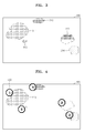
- FIG. 4 is a diagram for describing an example in which the setting unit 220 according to an embodiment sequentially sets indexes in respective blood flows.
- examples of blood flows segmented from an ultrasound image 400 are illustrated.
- the number of blood flows included in the ultrasound image 400 may be a total of five, and the number of blood flows equal to or greater than a threshold value among blood flows included in the ultrasound image 400 may be a total of five.
- the setting unit 220 generates an index as a numeral, generates a reference for setting an index as an amount of blood flow, and sets, as a threshold value, that the number of pixels corresponding to blood flow in the ultrasound image 400 is a B number.
- the setting unit 220 aligns a plurality of segmented blood flows according to a generated reference. For example, when it is assumed that the number of blood flows segmented from the ultrasound image 400 is a total of ten, the setting unit 220 aligns the ten blood flows in a descending order of an amount of blood flow. Subsequently, the setting unit 220 extracts only upper five blood flows in which the number of pixels corresponding to respective blood flows is equal to or more than the B number. Subsequently, the setting unit 220 sets an index in the order of 1 ⁇ 2 ⁇ 3 ⁇ 4 ⁇ 5 from blood flow having a largest amount of blood flow.
- the display unit 240 displays the ultrasound image, generated by the generation unit 210, on a screen of the image processing apparatus 20. Also, the display unit 240 displays objects of a plurality of blood flows segmented from the ultrasound image and the index set by the setting unit 220, on a screen of the image processing apparatus 20. In other words, as illustrated in FIG. 4 , the display unit 240 displays an index 420, set by the setting unit 220, at a position adjacent to a position of blood flow 410 corresponding thereto.
- the determination unit 230 determines blood flow corresponding to a selected index on the basis of an external single that selects one index from among a plurality of set indexes. In other words, the determination unit 230 receives an external signal that selects one index from among indexes displayed by the display unit 240, and determines blood flow corresponding to a selected index on the basis of the received external signal.
- the determination unit 230 determines blood flow corresponding to a selected index on the basis of an external signal.
- FIG. 5 is diagrams for describing an example in which the determination unit 230 according to an embodiment determines blood flow.
- FIG. 5 (a) an example in which blood flows segmented from an ultrasound image 510 and an index is set in some of the blood flows is illustrated.
- FIG. 5 (b) an example in which one of blood flows with an index set therein is determined is illustrated.
- the setting unit 220 segments blood flows from the ultrasound image 510, and sets an index in all or some of the blood flows on the basis of a predetermined reference and threshold value.
- An example in which the setting unit 220 operates has been described above with reference to FIG. 4 , and thus, its detailed description is not repeated.
- the display unit 240 displays an index, set by the setting unit 220, at a position adjacent to a position of blood flow corresponding thereto, and a user inputs an external signal, which selects one index from among a plurality of displayed indexes, to the image processing apparatus 20.
- the user may select one index from a plurality of indexes by using an input device such as a knob button, a trackball, a mouse, a keyboard, or a touch screen.
- the determination unit 230 determines blood flow corresponding to an index on the basis of an external signal. For example, when it is assumed that an external signal is a signal which selects '5' from among the indexes illustrated in FIG. 5 (a) , the determination unit 230 determines blood flow 532, corresponding to '5' among a plurality of blood flows displayed in an ultrasound image 520, as blood flow corresponding to the external signal.
- the display unit 240 displays information, corresponding to determined blood flow, on a screen of the image processing apparatus 20.
- the information corresponding to the determined blood flow denotes at least one or more of a position, direction, speed, and amount of the determined blood flow.
- the display unit 240 distinguishes and displays blood flow, determined by the determination unit 230 from among a plurality of blood flows included in the ROI 40, and the other blood flows, and displays a position, direction, speed, or amount of blood flow determined by the determination unit 230.
- the display unit 240 distinguishes and displays blood flow determined by the determination unit 230 and the other blood flows will be described in detail with reference FIG. 6 .
- FIG. 6 is diagrams for describing an example in which the display unit 240 according to an embodiment distinguishes and displays blood flow determined by the determination unit 230 and the other blood flows.
- the display unit 240 may display a looped curve at an outer portion of the blood flow 610 determined by the determination unit 230, and thus distinguish and display the blood flow 610 and the other blood flows.
- the display unit 240 may display the blood flow 620 determined by the determination unit 230 in a certain shape or color, and thus distinguish and display the blood flow 620 and the other blood flows.
- the display unit 240 may display only the blood flow 630 determined by the determination unit 230 without displaying the other blood flows, and thus distinguish and display the blood flow 630 and the other blood flows.
- the display unit 240 displays a position, direction, speed, or amount of blood flow determined by the determination unit 230.
- the display unit 240 extracts a position, direction, speed, or amount of the blood flow determined by determination unit 230 from among information about an amount of each of blood flows (included in the ROI 40 acquired by the generation unit 210) and information about a moving direction and speed of each blood flow, and displays the extraction result.
- FIG. 7 is a block diagram illustrating another example of an image processing apparatus 20 according to an embodiment.
- the image processing unit 20 includes a generation unit 210, a setting unit 220, a determination unit 230, a display unit 240, and a tracing unit 250.
- the image processing apparatus 20 of FIG. 7 is illustrated as including only elements associated with the present embodiment. Therefore, it may be understood by those skilled in the art that the image processing apparatus 20 may further include general-use elements in addition to the elements of FIG. 7 .
- the display unit 240 of the image processing apparatus 20 of FIG. 7 may be provided as an independent image display apparatus.
- the display unit 240 may include an output device, which is provided in the ultrasound diagnostic system 1, such as a display panel or a monitor, and a software module for driving the same.
- the generation unit 210, setting unit 220, determination unit 230, and tracing unit 250 of the image processing apparatus 20 of FIG. 7 may correspond to one or more processors.
- Each of the processors may be implemented as an array of a plurality of logic gates, or may be implemented as a combination of a general-use microprocessor and a memory that stores a program executable by the microprocessor. Also, it may be understood by one of ordinary skill in the art that the elements may be implemented as another type hardware.
- the tracing unit 250 traces a position of blood flow which is changed with time.
- blood flow of which a position is traced by the tracing unit 250 denotes blood flow determined by the determination unit 230.
- a position of blood flow may be changed by a breath of the object 30 with time.
- a position of the blood flow at the maximum inhalation time of the object 30 may differ from that of the blood flow at the maximum exhalation time of the object 30.
- the tracing unit 250 may trace the position of the blood flow which is changed by a breath or fine movement of the object 30, and may accurately acquire information about a current position of the blood flow which is determined by the determination unit 230.
- the tracing unit 250 receives information about the position of the blood flow from the determination unit 230, and compares the received information with an ultrasound image of the ROI 40 which is transmitted from the generation unit 210 in real time.
- the tracing unit 250 sets a region having a radius of D mm with respect to the position of the blood flow determined by the determination unit 230, and sets a region, corresponding to the set region, in the ultrasound image which is transmitted from the generation unit 210 in real time.
- the radius of D mm set by the tracing unit 250 may be preset by the image processing apparatus 20.
- the tracing unit 250 searches for the position of the blood flow, determined by the determination unit 230, in the region which is set in the ultrasound image, and transmits the search result (i.e., a current position of the blood flow) to the display unit 240.
- FIG. 8 is a flowchart illustrating an example of an ultrasound image processing method according to an embodiment.
- the ultrasound image processing method includes a plurality of operations that are performed in a time series by the ultrasound diagnostic system 1 and image processing apparatus 20 of FIGS. 1, 2 , and 7 .
- the above-described details of the ultrasound diagnostic system 1 and image processing apparatus 20 of FIGS. 1, 2 , and 7 may be applied to the ultrasound image processing method of FIG. 8 .
- the generation unit 210 generates an ultrasound image indicating the ROI 40 by using an echo signal which corresponds to an ultrasound wave irradiated onto the ROI 40.
- the ROI 40 denotes an internal certain region of the object 30 of which an image is generated, and for example, may be a region including a plurality of blood flows.
- the setting unit 220 sequentially sets respective indexes in a plurality of blood flows included in the ROI 40 on the basis of the ultrasound image.
- each of the indexes denotes a symbol for distinguishing and indicating each of the plurality of blood flows.
- the determination unit 230 determines blood flow corresponding to a selected index on the basis of an external signal for selecting one of the set indexes.
- the external signal may be a signal which is input by a user by using an input device (not shown), which includes an input device, such as a knob button, a trackball, a mouse, a keyboard, or a touch screen, and a software module for driving the same.
- the display unit 240 displays information corresponding to the determined blood flow.
- the information corresponding to the determined blood flow denotes at least one or more of a position, direction, speed, and amount of the determined blood flow.
- a plurality of indexes are sequentially and respectively set in a plurality of blood flows displayed on a screen, information of blood flow corresponding to one index selected from among the set plurality of indexes is output, and a user acquires information of desired blood flow among a plurality of blood flows included in an ROI.
- a position of blood flow which is changed due to a breath of an object is traced in real time, and thus, the user acquires accurate information of a blood flow speed.
- the above-described method may be written as computer programs and may be implemented in general-use digital computers that execute the programs using a computer-readable recording medium.
- Data structure used in the above-described method may be recorded in a computer-readable recording medium by using various methods.
- Examples of the computer-readable recording medium include magnetic storage media (e.g., ROM, RAM, USB, floppy disks, hard disks, etc.) and storage media such as optical recording media (e.g., CD-ROMs, or DVDs).
Landscapes
- Health & Medical Sciences (AREA)
- Life Sciences & Earth Sciences (AREA)
- Engineering & Computer Science (AREA)
- Biomedical Technology (AREA)
- Medical Informatics (AREA)
- Public Health (AREA)
- General Health & Medical Sciences (AREA)
- Physics & Mathematics (AREA)
- Molecular Biology (AREA)
- Pathology (AREA)
- Nuclear Medicine, Radiotherapy & Molecular Imaging (AREA)
- Animal Behavior & Ethology (AREA)
- Veterinary Medicine (AREA)
- Biophysics (AREA)
- Surgery (AREA)
- Radiology & Medical Imaging (AREA)
- Heart & Thoracic Surgery (AREA)
- Hematology (AREA)
- Physiology (AREA)
- Computer Vision & Pattern Recognition (AREA)
- Human Computer Interaction (AREA)
- Data Mining & Analysis (AREA)
- Databases & Information Systems (AREA)
- Primary Health Care (AREA)
- Epidemiology (AREA)
- General Physics & Mathematics (AREA)
- Multimedia (AREA)
- Theoretical Computer Science (AREA)
- Ultra Sonic Daignosis Equipment (AREA)
Abstract
Description
- This application claims the benefit of Korean Patent Application No.
10-2014-0026209, filed on March 5, 2014 - One or more embodiments of the present invention relate to a method, apparatus, and system for outputting information of blood flow included in a region of interest (ROI) based on selection information.
- A Doppler image generating apparatus irradiates an ultrasound wave onto an ROI, and measures a Doppler shift frequency of an echo signal reflected from blood flow included in the ROI, thereby detecting a distribution of blood flow in real time.
- Recently, provided is technology in which the Doppler image generating apparatus automatically finds a position of blood flow included in an ROI to dispose a color box or a sample volume (SV) at the position, estimates an angle of the blood flow in which the color box or the sample volume is disposed, and adjusts a slope of the color box or an angle of the sample volume.
- However, when blood flow included in an ROI shown in a Doppler image is provided in plurality, the Doppler image generating apparatus automatically disposes the color box or the sample volume in blood flow where an amount of blood flow is the largest, and for this reason, it is difficult to acquire information of blood flow desired by a user.
- One or more embodiments of the present invention include a method, apparatus, and system for outputting information of blood flow included in an ROI based on selection information.
- One or more embodiments of the present invention include a non-transitory computer-readable storage medium storing a program for executing the method in a computer.
- Additional aspects will be set forth in part in the description which follows and, in part, will be apparent from the description, or may be learned by practice of the presented embodiments.
- According to one or more embodiments of the present invention, an ultrasound image processing method includes: generating an ultrasound image indicating a region of interest (ROI) by using echo signals which corresponds to ultrasound waves irradiated onto the ROI; sequentially setting respective indexes in a plurality of blood flows included in the ROI detected based on the ultrasound image; determining blood flow corresponding to a selected index, based on an external signal for selecting one of the set indexes; and displaying information corresponding to the determined blood flow.
- According to one or more embodiments of the present invention, provided is a non-transitory computer-readable storage medium storing a program for executing the ultrasound image processing method in a computer.
- According to one or more embodiments of the present invention, an ultrasound image processing apparatus includes: a generation unit that generates an ultrasound image indicating a region of interest (ROI) by using echo signals which corresponds to ultrasound waves irradiated onto the ROI; a setting unit that sequentially sets respective indexes in a plurality of blood flows included in the ROI detected based on the ultrasound image; a determination unit that determines blood flow corresponding to a selected index, based on an external signal for selecting one of the set indexes; and a display unit that displays information corresponding to the determined blood flow.
- According to one or more embodiments of the present invention, an ultrasound diagnostic system includes: a probe that irradiates ultrasound waves onto a region of interest (ROI) included in an object, and receives echo signals which corresponds to an ultrasound wave; and an image processing apparatus that generates an ultrasound image indicating the ROI by using the echo signal, sequentially sets respective indexes in a plurality of blood flows included in the ROI detected based on the ultrasound image, determines blood flow corresponding to a selected index, based on an external signal for selecting one of the set indexes, and displays information corresponding to the determined blood flow.
- These and/or other aspects will become apparent and more readily appreciated from the following description of the embodiments, taken in conjunction with the accompanying drawings in which:
-
FIG. 1 is a configuration diagram illustrating an example of an ultrasound diagnostic system according to an embodiment; -
FIG. 2 is a block diagram illustrating an example of an image processing apparatus according to an embodiment; -
FIG. 3 is a diagram for describing an example in which a setting unit according to an embodiment segments a plurality of blood flows from an ultrasound image; -
FIG. 4 is a diagram for describing an example in which the setting unit according to an embodiment sequentially sets indexes in respective blood flows; -
FIG. 5 is diagrams for describing an example in which a determination unit according to an embodiment determines blood flow; -
FIG. 6 is diagrams for describing an example in which a display unit according to an embodiment distinguishes and displays blood flow determined by the determination unit and the other blood flows; -
FIG. 7 is a block diagram illustrating another example of an image processing apparatus according to an embodiment; and -
FIG. 8 is a flowchart illustrating an example of an ultrasound image processing method according to an embodiment. - Reference will now be made in detail to embodiments, examples of which are illustrated in the accompanying drawings, wherein like reference numerals refer to like elements throughout. In this regard, the present embodiments may have different forms and should not be construed as being limited to the descriptions set forth herein. Accordingly, the embodiments are merely described below, by referring to the figures, to explain aspects of the present description. Expressions such as "at least one of," when preceding a list of elements, modify the entire list of elements and do not modify the individual elements of the list.
-
FIG. 1 is a configuration diagram illustrating an example of an ultrasounddiagnostic system 1 according to an embodiment. - Referring to
FIG. 1 , the ultrasounddiagnostic system 1 includes aprobe 10 and animage processing apparatus 20. The ultrasounddiagnostic system 1 ofFIG. 1 is illustrated as including only elements associated with the present embodiment. Therefore, it may be understood by those skilled in the art that the ultrasounddiagnostic system 1 may further include general-use elements in addition to the elements ofFIG. 1 . - The
probe 10 irradiates ultrasound waves onto anROI 40 included in anobject 30, and receives echo signals corresponding to the irradiated ultrasound wave. In other words, theprobe 10 irradiates the ultrasound waves onto theROI 40. Theprobe 10 receives the echo signals that are signals reflected from each of tissues included in theROI 40. Theprobe 10 transmits the echo signals to ageneration unit 210 included in theimage processing apparatus 20. - Here, an ultrasound signal generating unit (not shown) of the
image processing apparatus 20 may perform a transmission beamforming operation in consideration of a position and size of theROI 40 to generate ultrasound waves which are irradiated by theprobe 10. A detailed method of generating ultrasound waves irradiated by theprobe 10 is obvious to one of ordinary skill in the art, and thus, its detailed description is not provided. - When a plurality of transducers (not shown) included in the
probe 10 respectively irradiate ultrasound waves onto an internal certain part of theobject 30, the ultrasound waves are partially reflected from layers between a plurality of tissues. In particular, the ultrasound waves may be reflected from parts (for example, blood cells of blood plasma, and small tissues of organs) in which a density is changed in theobject 30. Reflected signals vibrate the transducers (not shown), which output electrical pulses based on the vibrations. Theprobe 10 transmits the electrical pulses to thegeneration unit 210. - Here, the
object 30 denotes a target of which an image is to be generated, and for example, may be a patient. However, the present embodiment is not limited thereto. TheROI 40 denotes an internal certain region of theobject 30 of which an image is generated, and for example, may be a region including a plurality of blood flows. However, the present embodiment is not limited thereto. - The
image processing apparatus 20 generates an ultrasound image indicating theROI 40 by using the echo signals transmitted from theprobe 10. Theimage processing apparatus 20 detects a plurality of blood flows included in theROI 40 on the basis of the generated ultrasound image, and sequentially sets respective indexes in the detected blood flows. Theimage processing apparatus 20 determines blood flow corresponding to a selected index on the basis of an external signal for selecting one of the indexes. Here, the external signal may be a signal which is input by a user by using an input device (not shown), which includes an input device, such as a knob button, a trackball, a mouse, a keyboard, or a touch screen, and a software module for driving the same. Theimage processing apparatus 20 displays information corresponding to the determined blood flow. - Hereinafter, a detailed operation of the
image processing apparatus 20 will be described with reference toFIGS. 2 to 8 . -
FIG. 2 is a block diagram illustrating an example of theimage processing apparatus 20 according to an embodiment. - Referring to
FIG. 2 , theimage processing apparatus 20 includes ageneration unit 210, asetting unit 220, adetermination unit 230, and adisplay unit 240. Theimage processing apparatus 20 ofFIG. 2 is illustrated as including only elements associated with the present embodiment. Therefore, it may be understood by those skilled in the art that theimage processing apparatus 20 may further include general-use elements in addition to the elements ofFIG. 2 . - Moreover, it is well known to one of ordinary skill in the art that the
display unit 240 of theimage processing apparatus 20 ofFIG. 2 may be provided as an independent image display apparatus. In other words, thedisplay unit 240 may include an output device, which is provided in the ultrasounddiagnostic system 1, such as a display panel or a monitor, and a software module for driving the same. - The
generation unit 210, settingunit 220, anddetermination unit 230 of theimage processing apparatus 20 ofFIG. 2 may correspond to one or more processors. Each of the processors may be implemented as an array of a plurality of logic gates, or may be implemented as a combination of a general-use microprocessor and a memory that stores a program executable by the microprocessor. Also, it may be understood by one of ordinary skill in the art that the elements may be implemented as another type hardware. - The
generation unit 210 generates an ultrasound image indicating theROI 40 by using an echo signal corresponding to an ultrasound wave irradiated onto theROI 40. In detail, thegeneration unit 210 analog-digital converts the echo signal (i.e., electrical pulses) transmitted from theprobe 10 to generate a digital signal. Thegeneration unit 210 performs reception beamforming of the digital signal to generate a reception focusing signal, and generates ultrasound data by using the reception focusing signal. Here, the ultrasound data may include an in-phase/quadrature (IQ) signal, but is not limited thereto. - The
generation unit 210 generates the ultrasound image indicating theROI 40 by using the ultrasound data. Here, theROI 40 denotes an internal certain region of theobject 30 of which an image is generated, and for example, may be a region including a plurality of blood flows. However, the present embodiment is not limited thereto. - Here, an ultrasound image generated by the
generation unit 210 denotes a Doppler mode image. In other words, thegeneration unit 210 acquires information about an amount of each of the blood flows included in theROI 40 and information about a moving direction and speed of blood flow, by using the ultrasound data, and generates the Doppler mode image on the basis of the acquired information. - The
setting unit 220 sequentially sets respective indexes in the plurality of blood flows included in theROI 40 detected based on the ultrasound image. In other words, thesetting unit 220 detects a plurality of blood flows included in theROI 40 on the basis of the ultrasound image, and sequentially sets respective indexes in the detected plurality of blood flows. - For example, the
setting unit 220 generates a reference for setting an index on the basis of the external signal. Thesetting unit 220 segments a plurality of blood flows from the ultrasound image. It is described that the reference for setting the index is generated and then the blood flows are segmented from the ultrasound image, but the present embodiment is not limited to the above-described sequence. In other words, thesetting unit 220 may segment the blood flows from the ultrasound image before generating the reference for setting the index, and the above-described two operations may be simultaneously performed. Furthermore, thesetting unit 220 aligns the segmented blood flows according to the generated reference, and sequentially sets respective indexes in the aligned blood flows. Hereinafter, an example in which thesetting unit 220 operates will be described in detail. - The
setting unit 220 generates the reference for setting the index on the basis of the external signal. Here, the index denotes a symbol for distinguishing and indicating each of a plurality of blood flows. For example, the index may be a numeral or a sign which is displayed at a position adjacent to blood flow, or may be different shapes or colors for distinguishing respective blood flows. - Information of the reference for setting the index may be input to the
image processing apparatus 20 by a user by using the external signal. In other words, the external signal may be a signal which is input by a user by using an input device (not shown), which includes an input device, such as a knob button, a trackball, a mouse, a keyboard, or a touch screen, and a software module for driving the same. - Here, the reference for setting the index may be one of a blood flow speed, a blood flow direction, an amount of blood flow, and a position of blood flow included in an ultrasound image. For example, the
setting unit 220 may generate, as the reference for setting the index, an ascending order of an average speed of blood flow (or the highest speed of the blood flow) or a descending order of the average speed of the blood flow (or the highest speed of the blood flow). Alternatively, thesetting unit 220 may set an index by using only blood flows which flow in a predetermined direction among a plurality of blood flows. Alternatively, thesetting unit 220 may generate, as the reference for setting the index, an ascending order of an amount of blood flow or a descending order of the amount of blood flow. Here, thesetting unit 220 may determine the ascending order of the amount of blood flow or the descending order of the amount of blood flow in correspondence with the number of pixels indicating respective blood flows in the ultrasound image. Alternatively, thesetting unit 220 may generate, as the reference for setting the index, a clockwise direction (or a counterclockwise direction) with respect to the center of the ultrasound image. Alternatively, thesetting unit 220 may generate, as the reference for setting the index, a downward direction from a top, a right direction from the left, and an edge direction from the center in the ultrasound image. However, the reference generated by thesetting unit 220 is not limited to the above-described examples, and all references for distinguishing and indicating each blood flow may be applied without being limited. - Moreover, the
setting unit 220 may set a threshold value for the above-described reference on the basis of the external signal. For example, when it is assumed that the reference for setting the index is an average speed of blood flow, thesetting unit 220 may set A cm/sec as the threshold value. Alternatively, when it is assumed that the reference for setting the index is an amount of blood flow, thesetting unit 220 may set, as the threshold value, that the number of pixels corresponding to blood flow in the ultrasound image is a B number. Alternatively, when it is assumed that the reference for setting the index is a position of blood flow, thesetting unit 220 may set, as the threshold value, that a radius with respect to the center of the ultrasound image is within C cm. - The
setting unit 220 segments a plurality of blood flows from the ultrasound image. Hereinafter, an example in which thesetting unit 220 segments a plurality of blood flows from an ultrasound image will be described in detail with reference toFIG. 3 . -
FIG. 3 is a diagram for describing an example in which thesetting unit 220 according to an embodiment segments a plurality of blood flows from an ultrasound image. - Referring to
FIG. 3 , examples of blood flows 311 to 315 segmented from anultrasound image 300 are illustrated.FIG. 3 illustrates a total of five the blood flows 311 to 315 included in theROI 40, but the present embodiment is not limited thereto. - The
setting unit 220 segments objects included in theultrasound image 300. For example, thesetting unit 220 may segment the objects from theultrasound image 300 on the basis of a region growing method, but is not limited thereto. - Subsequently, the
setting unit 220 extracts theobjects 311 to 315 corresponding to blood flow from among the segmented objects. For example, when ultrasound data corresponding to each of the segmented objects includes formation about a moving direction or speed, thesetting unit 220 determines that the segmented objects correspond to the blood flow, and extracts the segmented objects as theobjects 311 to 315 corresponding to the blood flow. - Referring again to
FIG. 2 , thesetting unit 220 aligns the segmented blood flows according to a generated reference, and sequentially sets respective indexes in the aligned blood flows. Hereinafter, an example in which thesetting unit 220 sequentially sets respective indexes in blood flows will be described with reference toFIG. 4 . -
FIG. 4 is a diagram for describing an example in which thesetting unit 220 according to an embodiment sequentially sets indexes in respective blood flows. - Referring to
FIG. 4 , examples of blood flows segmented from anultrasound image 400 are illustrated. In five blood flows illustrated inFIG. 4 the number of blood flows included in theultrasound image 400 may be a total of five, and the number of blood flows equal to or greater than a threshold value among blood flows included in theultrasound image 400 may be a total of five. In the following description, it is assumed that thesetting unit 220 generates an index as a numeral, generates a reference for setting an index as an amount of blood flow, and sets, as a threshold value, that the number of pixels corresponding to blood flow in theultrasound image 400 is a B number. - The
setting unit 220 aligns a plurality of segmented blood flows according to a generated reference. For example, when it is assumed that the number of blood flows segmented from theultrasound image 400 is a total of ten, thesetting unit 220 aligns the ten blood flows in a descending order of an amount of blood flow. Subsequently, thesetting unit 220 extracts only upper five blood flows in which the number of pixels corresponding to respective blood flows is equal to or more than the B number. Subsequently, thesetting unit 220 sets an index in the order of 1→2→3→4→5 from blood flow having a largest amount of blood flow. - Referring again to
FIG. 2 , thedisplay unit 240 displays the ultrasound image, generated by thegeneration unit 210, on a screen of theimage processing apparatus 20. Also, thedisplay unit 240 displays objects of a plurality of blood flows segmented from the ultrasound image and the index set by thesetting unit 220, on a screen of theimage processing apparatus 20. In other words, as illustrated inFIG. 4 , thedisplay unit 240 displays anindex 420, set by thesetting unit 220, at a position adjacent to a position ofblood flow 410 corresponding thereto. - The
determination unit 230 determines blood flow corresponding to a selected index on the basis of an external single that selects one index from among a plurality of set indexes. In other words, thedetermination unit 230 receives an external signal that selects one index from among indexes displayed by thedisplay unit 240, and determines blood flow corresponding to a selected index on the basis of the received external signal. Hereinafter, an example in which thedetermination unit 230 determines blood flow corresponding to a selected index on the basis of an external signal will be described in detail with reference toFIG. 5 . -
FIG. 5 is diagrams for describing an example in which thedetermination unit 230 according to an embodiment determines blood flow. - In
FIG. 5 (a) , an example in which blood flows segmented from anultrasound image 510 and an index is set in some of the blood flows is illustrated. InFIG. 5 (b) , an example in which one of blood flows with an index set therein is determined is illustrated. - Referring to
FIG. 5 (a) , thesetting unit 220 segments blood flows from theultrasound image 510, and sets an index in all or some of the blood flows on the basis of a predetermined reference and threshold value. An example in which thesetting unit 220 operates has been described above with reference toFIG. 4 , and thus, its detailed description is not repeated. - The
display unit 240 displays an index, set by thesetting unit 220, at a position adjacent to a position of blood flow corresponding thereto, and a user inputs an external signal, which selects one index from among a plurality of displayed indexes, to theimage processing apparatus 20. For example, the user may select one index from a plurality of indexes by using an input device such as a knob button, a trackball, a mouse, a keyboard, or a touch screen. - Referring to
FIG. 5 (b) , thedetermination unit 230 determines blood flow corresponding to an index on the basis of an external signal. For example, when it is assumed that an external signal is a signal which selects '5' from among the indexes illustrated inFIG. 5 (a) , thedetermination unit 230 determinesblood flow 532, corresponding to '5' among a plurality of blood flows displayed in anultrasound image 520, as blood flow corresponding to the external signal. - Referring again to
FIG. 2 , thedisplay unit 240 displays information, corresponding to determined blood flow, on a screen of theimage processing apparatus 20. Here, the information corresponding to the determined blood flow denotes at least one or more of a position, direction, speed, and amount of the determined blood flow. - In other words, the
display unit 240 distinguishes and displays blood flow, determined by thedetermination unit 230 from among a plurality of blood flows included in theROI 40, and the other blood flows, and displays a position, direction, speed, or amount of blood flow determined by thedetermination unit 230. Hereinafter, an example in which thedisplay unit 240 distinguishes and displays blood flow determined by thedetermination unit 230 and the other blood flows will be described in detail with referenceFIG. 6 . -
FIG. 6 is diagrams for describing an example in which thedisplay unit 240 according to an embodiment distinguishes and displays blood flow determined by thedetermination unit 230 and the other blood flows. - Referring to
FIGS. 6 (a) to (c) , an example in which thedisplay unit 240 distinguishes and displays blood flows 610, 620 and 630 determined by thedetermination unit 230 and the other blood flows is illustrated. Referring toFIG. 6 (a) , thedisplay unit 240 may display a looped curve at an outer portion of theblood flow 610 determined by thedetermination unit 230, and thus distinguish and display theblood flow 610 and the other blood flows. Referring toFIG. 6 (b) , thedisplay unit 240 may display theblood flow 620 determined by thedetermination unit 230 in a certain shape or color, and thus distinguish and display theblood flow 620 and the other blood flows. Referring toFIG. 6 (c) , thedisplay unit 240 may display only theblood flow 630 determined by thedetermination unit 230 without displaying the other blood flows, and thus distinguish and display theblood flow 630 and the other blood flows. - Referring again to
FIG. 2 , thedisplay unit 240 displays a position, direction, speed, or amount of blood flow determined by thedetermination unit 230. In detail, thedisplay unit 240 extracts a position, direction, speed, or amount of the blood flow determined bydetermination unit 230 from among information about an amount of each of blood flows (included in theROI 40 acquired by the generation unit 210) and information about a moving direction and speed of each blood flow, and displays the extraction result. -
FIG. 7 is a block diagram illustrating another example of animage processing apparatus 20 according to an embodiment. - Referring to
FIG. 7 , theimage processing unit 20 includes ageneration unit 210, asetting unit 220, adetermination unit 230, adisplay unit 240, and atracing unit 250. Theimage processing apparatus 20 ofFIG. 7 is illustrated as including only elements associated with the present embodiment. Therefore, it may be understood by those skilled in the art that theimage processing apparatus 20 may further include general-use elements in addition to the elements ofFIG. 7 . - Moreover, it is well known to one of ordinary skill in the art that the
display unit 240 of theimage processing apparatus 20 ofFIG. 7 may be provided as an independent image display apparatus. In other words, thedisplay unit 240 may include an output device, which is provided in the ultrasounddiagnostic system 1, such as a display panel or a monitor, and a software module for driving the same. - Moreover, the
generation unit 210, settingunit 220,determination unit 230, andtracing unit 250 of theimage processing apparatus 20 ofFIG. 7 may correspond to one or more processors. Each of the processors may be implemented as an array of a plurality of logic gates, or may be implemented as a combination of a general-use microprocessor and a memory that stores a program executable by the microprocessor. Also, it may be understood by one of ordinary skill in the art that the elements may be implemented as another type hardware. - Moreover, operations of the
generation unit 210, settingunit 220,determination unit 230, anddisplay unit 240 of theimage processing apparatus 20 ofFIG. 7 are as described above with reference toFIG. 2 , and thus, their detailed descriptions are not repeated below. - The
tracing unit 250 traces a position of blood flow which is changed with time. Here, blood flow of which a position is traced by thetracing unit 250 denotes blood flow determined by thedetermination unit 230. - A position of blood flow may be changed by a breath of the
object 30 with time. In other words, a position of the blood flow at the maximum inhalation time of theobject 30 may differ from that of the blood flow at the maximum exhalation time of theobject 30. Thetracing unit 250 may trace the position of the blood flow which is changed by a breath or fine movement of theobject 30, and may accurately acquire information about a current position of the blood flow which is determined by thedetermination unit 230. - For example, the
tracing unit 250 receives information about the position of the blood flow from thedetermination unit 230, and compares the received information with an ultrasound image of theROI 40 which is transmitted from thegeneration unit 210 in real time. In detail, thetracing unit 250 sets a region having a radius of D mm with respect to the position of the blood flow determined by thedetermination unit 230, and sets a region, corresponding to the set region, in the ultrasound image which is transmitted from thegeneration unit 210 in real time. Here, the radius of D mm set by thetracing unit 250 may be preset by theimage processing apparatus 20. Subsequently, thetracing unit 250 searches for the position of the blood flow, determined by thedetermination unit 230, in the region which is set in the ultrasound image, and transmits the search result (i.e., a current position of the blood flow) to thedisplay unit 240. -
FIG. 8 is a flowchart illustrating an example of an ultrasound image processing method according to an embodiment. - Referring to
FIG. 8 , the ultrasound image processing method includes a plurality of operations that are performed in a time series by the ultrasounddiagnostic system 1 andimage processing apparatus 20 ofFIGS. 1, 2 , and7 . Thus, although not described below, the above-described details of the ultrasounddiagnostic system 1 andimage processing apparatus 20 ofFIGS. 1, 2 , and7 may be applied to the ultrasound image processing method ofFIG. 8 . - In
operation 810, thegeneration unit 210 generates an ultrasound image indicating theROI 40 by using an echo signal which corresponds to an ultrasound wave irradiated onto theROI 40. Here, theROI 40 denotes an internal certain region of theobject 30 of which an image is generated, and for example, may be a region including a plurality of blood flows. - In
operation 820, thesetting unit 220 sequentially sets respective indexes in a plurality of blood flows included in theROI 40 on the basis of the ultrasound image. Here, each of the indexes denotes a symbol for distinguishing and indicating each of the plurality of blood flows. - In
operation 830, thedetermination unit 230 determines blood flow corresponding to a selected index on the basis of an external signal for selecting one of the set indexes. Here, the external signal may be a signal which is input by a user by using an input device (not shown), which includes an input device, such as a knob button, a trackball, a mouse, a keyboard, or a touch screen, and a software module for driving the same. - In
operation 840, thedisplay unit 240 displays information corresponding to the determined blood flow. Here, the information corresponding to the determined blood flow denotes at least one or more of a position, direction, speed, and amount of the determined blood flow. - As described above, according to the one or more of the above embodiments of the present invention, a plurality of indexes are sequentially and respectively set in a plurality of blood flows displayed on a screen, information of blood flow corresponding to one index selected from among the set plurality of indexes is output, and a user acquires information of desired blood flow among a plurality of blood flows included in an ROI.
- Moreover, a position of blood flow which is changed due to a breath of an object is traced in real time, and thus, the user acquires accurate information of a blood flow speed.
- The above-described method may be written as computer programs and may be implemented in general-use digital computers that execute the programs using a computer-readable recording medium. Data structure used in the above-described method may be recorded in a computer-readable recording medium by using various methods. Examples of the computer-readable recording medium include magnetic storage media (e.g., ROM, RAM, USB, floppy disks, hard disks, etc.) and storage media such as optical recording media (e.g., CD-ROMs, or DVDs).
- It should be understood that the exemplary embodiments described herein should be considered in a descriptive sense only and not for purposes of limitation. Descriptions of features or aspects within each embodiment should typically be considered as available for other similar features or aspects in other embodiments.
- While one or more embodiments of the present invention have been described with reference to the figures, it will be understood by those of ordinary skill in the art that various changes in form and details may be made therein without departing from the spirit and scope of the present invention as defined by the following claims.
Claims (15)
- An ultrasound image processing method comprising:generating an ultrasound image indicating a region of interest (ROI) by using echo signals which correspond to ultrasound waves irradiated onto the ROI;sequentially setting respective indexes in a plurality of blood flows included in the ROI detected based on the ultrasound image;determining blood flow corresponding to a selected index, based on an external signal for selecting one of the set indexes; anddisplaying information corresponding to the determined blood flow.
- The ultrasound image processing method of claim 1, wherein information corresponding to the determined blood flow comprises at least one of a position, direction, speed, and amount of the blood flow.
- The ultrasound image processing method of claim 1, wherein the setting comprises:generating a reference for setting each of the indexes, based on an external signal;segmenting the plurality of blood flows from the ultrasound image, and aligning the segmented blood flows according to the generated reference; andsequentially setting the respective indexes in the aligned blood flows.
- The ultrasound image processing method of claim 3, wherein the reference comprises at least one of a position, direction, speed, and amount of each of the blood flows in the ultrasound image.
- The ultrasound image processing method of claim 1, wherein the determining comprises receiving an external signal which selects one index from among the indexes displayed on a screen, and determining blood flow corresponding to a selected index, based on the external signal.
- The ultrasound image processing method of claim 1, further comprising tracing and displaying a position of the determined blood flow which is changed with time.
- The ultrasound image processing method of claim 1, which the ultrasound image comprises a Doppler mode image.
- A non-transitory computer-readable storage medium storing a program for executing the ultrasound image processing method of claim 1 in a computer.
- An ultrasound image processing apparatus comprising:a generation unit that generates an ultrasound image indicating a region of interest (ROI) by using echo signals which corresponds to ultrasound waves irradiated onto the ROI;a setting unit that sequentially sets respective indexes in a plurality of blood flows included in the ROI detected based on the ultrasound image;a determination unit that determines blood flow corresponding to a selected index, based on an external signal for selecting one of the set indexes; anda display unit that displays information corresponding to the determined blood flow.
- The ultrasound image processing apparatus of claim 9, wherein information corresponding to the determined blood flow comprises at least one of a position, direction, speed, and amount of the blood flow.
- The ultrasound image processing apparatus of claim 9, wherein the setting unit generates a reference for setting each of the indexes, based on an external signal, segments the plurality of blood flows from the ultrasound image, aligns the segmented blood flows according to the generated reference, and sequentially sets the respective indexes in the aligned blood flows.
- The ultrasound image processing apparatus of claim 11, wherein the reference comprises at least one of a position, direction, speed, and amount of each of the blood flows in the ultrasound image.
- The ultrasound image processing apparatus of claim 9, wherein the determination unit receives an external signal which selects one index from among the indexes displayed by the display unit, and determines blood flow corresponding to a selected index, based on the external signal.
- The ultrasound image processing apparatus of claim 9, further comprising a tracing unit that traces a position of the determined blood flow which is changed with time.
- The ultrasound image processing apparatus of claim 9, which the ultrasound image comprises a Doppler mode image.
Applications Claiming Priority (1)
| Application Number | Priority Date | Filing Date | Title |
|---|---|---|---|
| KR1020140026209A KR102243022B1 (en) | 2014-03-05 | 2014-03-05 | Method, apparatus and system for outputting information of blood flow included in a region of interest based on selection information |
Publications (2)
| Publication Number | Publication Date |
|---|---|
| EP2915491A1 true EP2915491A1 (en) | 2015-09-09 |
| EP2915491B1 EP2915491B1 (en) | 2023-04-26 |
Family
ID=51178639
Family Applications (1)
| Application Number | Title | Priority Date | Filing Date |
|---|---|---|---|
| EP14171251.3A Active EP2915491B1 (en) | 2014-03-05 | 2014-06-05 | Method, apparatus, and system for outputting information of blood flow included in region of interest based on selection information |
Country Status (4)
| Country | Link |
|---|---|
| US (1) | US9390510B2 (en) |
| EP (1) | EP2915491B1 (en) |
| KR (1) | KR102243022B1 (en) |
| CN (1) | CN104887271B (en) |
Families Citing this family (3)
| Publication number | Priority date | Publication date | Assignee | Title |
|---|---|---|---|---|
| KR20160087221A (en) * | 2015-01-13 | 2016-07-21 | 삼성메디슨 주식회사 | Ultrasonic diagnostic apparatus and operating method for the same |
| CN113967036B (en) * | 2017-04-28 | 2024-08-30 | 深圳迈瑞生物医疗电子股份有限公司 | Ultrasonic imaging device and method for detecting blood vessel wall shear index using ultrasound |
| CN113450329B (en) * | 2021-06-29 | 2023-01-10 | 广州医软智能科技有限公司 | Microcirculation image blood vessel branch erythrocyte flow rate calculation method and system |
Citations (3)
| Publication number | Priority date | Publication date | Assignee | Title |
|---|---|---|---|---|
| WO2009013686A2 (en) * | 2007-07-26 | 2009-01-29 | Koninklijke Philips Electronics, N.V. | Systems and methods for automated image selection in doppler ultrasound imaging systems |
| US20100125204A1 (en) * | 2008-11-19 | 2010-05-20 | Jae Heung Yoo | Ultrasound System And Method Of Forming Three-Dimensional Ultrasound Images |
| US20130150717A1 (en) * | 2011-12-08 | 2013-06-13 | Takeshi Sato | Ultrasonic diagnosis apparatus, image processing apparatus, and image processing method |
Family Cites Families (31)
| Publication number | Priority date | Publication date | Assignee | Title |
|---|---|---|---|---|
| JPH0681616B2 (en) * | 1988-05-26 | 1994-10-19 | 淑 中山 | Ultrasonic diagnostic equipment |
| US4886059A (en) * | 1988-06-23 | 1989-12-12 | Applied Biometrics, Incorporated | Endotracheal tube with asymmetric balloon |
| US5148809A (en) * | 1990-02-28 | 1992-09-22 | Asgard Medical Systems, Inc. | Method and apparatus for detecting blood vessels and displaying an enhanced video image from an ultrasound scan |
| JP3524129B2 (en) * | 1992-12-28 | 2004-05-10 | 株式会社東芝 | Ultrasound color Doppler diagnostic system |
| JPH06217975A (en) * | 1993-01-28 | 1994-08-09 | Toshiba Medical Eng Co Ltd | Ultrasonic doppler diagnostic device |
| JPH09135830A (en) * | 1995-11-15 | 1997-05-27 | Shimadzu Corp | Ultrasound diagnostic equipment |
| US5838592A (en) * | 1996-10-14 | 1998-11-17 | Diasonics Ultrasound Inc. | Method and apparatus for measuring fetus head and abdominal circumference |
| JP3403917B2 (en) | 1997-05-26 | 2003-05-06 | 株式会社日立メディコ | Ultrasonic tomograph |
| KR100255730B1 (en) * | 1997-12-15 | 2000-05-01 | 이민화 | Ultrasonic color doppler system for displaying artery and vein |
| US5928153A (en) * | 1998-11-24 | 1999-07-27 | Hui-Hua Chiang | Ultrasound flow velocity and Doppler angle measurement method and system |
| DE60012305T2 (en) * | 1999-12-07 | 2005-08-18 | Koninklijke Philips Electronics N.V. | ULTRASONIC IMAGE PROCESSING SYSTEM AND SYSTEM FOR PRESENTING A COMPOSIT BILTH SEQUENCE OF A TYPE OF ARTERY |
| JP2001204729A (en) | 2000-01-31 | 2001-07-31 | Toshiba Corp | Ultrasound image diagnostic equipment |
| JP4127827B2 (en) * | 2004-06-30 | 2008-07-30 | オリンパス株式会社 | Ultrasonic diagnostic equipment |
| US20060058610A1 (en) * | 2004-08-31 | 2006-03-16 | General Electric Company | Increasing the efficiency of quantitation in stress echo |
| US8047993B2 (en) * | 2004-12-08 | 2011-11-01 | Industrial Technology Research Institute | Quantitative non-invasive method for detecting degree of malignancy in tumors and application thereof |
| WO2007069166A2 (en) * | 2005-12-15 | 2007-06-21 | Koninklijke Philips Electronics, N.V. | A method for determining a degree of pulsatility in angiography |
| KR100951595B1 (en) * | 2006-10-17 | 2010-04-09 | 주식회사 메디슨 | Ultrasound System and Method for Forming Ultrasound Images |
| JP4907382B2 (en) | 2007-02-23 | 2012-03-28 | ジーイー・メディカル・システムズ・グローバル・テクノロジー・カンパニー・エルエルシー | Ultrasonic image display method and ultrasonic diagnostic apparatus |
| JP5639764B2 (en) * | 2007-03-08 | 2014-12-10 | シンク−アールエックス,リミティド | Imaging and tools for use with moving organs |
| EP2358269B1 (en) * | 2007-03-08 | 2019-04-10 | Sync-RX, Ltd. | Image processing and tool actuation for medical procedures |
| US7920731B2 (en) * | 2007-03-27 | 2011-04-05 | Siemens Medical Solutions Usa, Inc. | Bleeding detection using a blanket ultrasound device |
| US20080269611A1 (en) * | 2007-04-24 | 2008-10-30 | Gianni Pedrizzetti | Flow characteristic imaging in medical diagnostic ultrasound |
| EP2036497A1 (en) * | 2007-09-17 | 2009-03-18 | Amid s.r.l. | Method for generating quantitative images of the flow potential of a region under investigation |
| TW201038256A (en) * | 2009-04-23 | 2010-11-01 | Univ Nat Taiwan | Method for renal vascular perfusion examination with power doppler ultrasonography |
| CN102573647A (en) * | 2009-10-01 | 2012-07-11 | 皇家飞利浦电子股份有限公司 | Contrast-enhanced ultrasound assessment of liver blood flow for monitoring liver therapy |
| JP2014518609A (en) * | 2011-03-03 | 2014-08-07 | テルサス ファーマシューティカルズ リミテッド ライアビリティ カンパニー | Compositions and methods comprising C16: 1n7-palmitreate |
| US20130046168A1 (en) * | 2011-08-17 | 2013-02-21 | Lei Sui | Method and system of characterization of carotid plaque |
| WO2013088320A1 (en) | 2011-12-16 | 2013-06-20 | Koninklijke Philips Electronics N.V. | Automatic blood vessel identification by name |
| TWI482613B (en) * | 2011-12-27 | 2015-05-01 | Ind Tech Res Inst | Signal analysis method, method for analyzing ultrasound image, and ultrasound imaging system using the same |
| KR101348773B1 (en) * | 2011-12-29 | 2014-01-09 | 삼성메디슨 주식회사 | Ultrasound system and method for providing turbulent flow information based on doppler doppler |
| CN104414684B (en) * | 2013-08-19 | 2017-04-12 | 柯尼卡美能达株式会社 | Ultrasound diagnostic device and image processing method for ultrasound diagnostic device |
-
2014
- 2014-03-05 KR KR1020140026209A patent/KR102243022B1/en active Active
- 2014-06-05 EP EP14171251.3A patent/EP2915491B1/en active Active
- 2014-07-25 CN CN201410361411.3A patent/CN104887271B/en active Active
- 2014-07-28 US US14/444,565 patent/US9390510B2/en active Active
Patent Citations (3)
| Publication number | Priority date | Publication date | Assignee | Title |
|---|---|---|---|---|
| WO2009013686A2 (en) * | 2007-07-26 | 2009-01-29 | Koninklijke Philips Electronics, N.V. | Systems and methods for automated image selection in doppler ultrasound imaging systems |
| US20100125204A1 (en) * | 2008-11-19 | 2010-05-20 | Jae Heung Yoo | Ultrasound System And Method Of Forming Three-Dimensional Ultrasound Images |
| US20130150717A1 (en) * | 2011-12-08 | 2013-06-13 | Takeshi Sato | Ultrasonic diagnosis apparatus, image processing apparatus, and image processing method |
Also Published As
| Publication number | Publication date |
|---|---|
| EP2915491B1 (en) | 2023-04-26 |
| US20150254867A1 (en) | 2015-09-10 |
| CN104887271A (en) | 2015-09-09 |
| KR20150104457A (en) | 2015-09-15 |
| US9390510B2 (en) | 2016-07-12 |
| KR102243022B1 (en) | 2021-04-21 |
| CN104887271B (en) | 2020-03-24 |
Similar Documents
| Publication | Publication Date | Title |
|---|---|---|
| JP7230255B2 (en) | Analysis device and analysis program | |
| CN108733857B (en) | Ultrasonic elastography device and elastography result evaluation method | |
| JP7159025B2 (en) | Diagnostic device and diagnostic method | |
| US20190254629A1 (en) | Method and system for displaying ultrasonic elastic measurement | |
| EP3554379B1 (en) | Prenatal ultrasound imaging | |
| CN114072060A (en) | Ultrasonic imaging method and ultrasonic imaging system | |
| US11602332B2 (en) | Methods and systems for multi-mode ultrasound imaging | |
| JP7195374B2 (en) | Acoustic wave measuring device and method of operating acoustic wave measuring device | |
| JP7490839B2 (en) | Analysis device and analysis program | |
| JP2023160986A (en) | Ultrasonic diagnostic equipment and analysis equipment | |
| CN114375179B (en) | Ultrasonic image analysis method, ultrasonic imaging system and computer storage medium | |
| CN109069113B (en) | Ultrasonic imaging device and method for detecting vascular wall shear index by utilizing ultrasonic | |
| CN110300548A (en) | Ultrasound Evaluation anatomical features | |
| US9390510B2 (en) | Method, apparatus, and system for outputting information of blood flow included in region of interest based on selection information | |
| CN103190931A (en) | Ultrasonic device and method of generating ultrasonic image using vector doppler | |
| EP2740408B1 (en) | Ultrasound diagnostic method and ultrasound diagnostic apparatus using volume data | |
| EP2901939A1 (en) | Ultrasonic measurement apparatus and ultrasonic measurement method | |
| US20190183453A1 (en) | Ultrasound imaging system and method for obtaining head progression measurements | |
| CN110801245B (en) | Ultrasonic image processing apparatus and storage medium | |
| JP4761999B2 (en) | Ultrasonic diagnostic apparatus, image processing method thereof, and image processing program thereof | |
| JP2025098558A (en) | Ultrasonic tomographic image processing apparatus and ultrasonic tomographic image processing program | |
| JP2018000673A (en) | Ultrasonic diagnostic apparatus and control method thereof |
Legal Events
| Date | Code | Title | Description |
|---|---|---|---|
| PUAI | Public reference made under article 153(3) epc to a published international application that has entered the european phase |
Free format text: ORIGINAL CODE: 0009012 |
|
| AK | Designated contracting states |
Kind code of ref document: A1 Designated state(s): AL AT BE BG CH CY CZ DE DK EE ES FI FR GB GR HR HU IE IS IT LI LT LU LV MC MK MT NL NO PL PT RO RS SE SI SK SM TR |
|
| AX | Request for extension of the european patent |
Extension state: BA ME |
|
| 17P | Request for examination filed |
Effective date: 20160229 |
|
| RBV | Designated contracting states (corrected) |
Designated state(s): AL AT BE BG CH CY CZ DE DK EE ES FI FR GB GR HR HU IE IS IT LI LT LU LV MC MK MT NL NO PL PT RO RS SE SI SK SM TR |
|
| STAA | Information on the status of an ep patent application or granted ep patent |
Free format text: STATUS: EXAMINATION IS IN PROGRESS |
|
| 17Q | First examination report despatched |
Effective date: 20190520 |
|
| GRAP | Despatch of communication of intention to grant a patent |
Free format text: ORIGINAL CODE: EPIDOSNIGR1 |
|
| STAA | Information on the status of an ep patent application or granted ep patent |
Free format text: STATUS: GRANT OF PATENT IS INTENDED |
|
| INTG | Intention to grant announced |
Effective date: 20221202 |
|
| GRAS | Grant fee paid |
Free format text: ORIGINAL CODE: EPIDOSNIGR3 |
|
| GRAA | (expected) grant |
Free format text: ORIGINAL CODE: 0009210 |
|
| STAA | Information on the status of an ep patent application or granted ep patent |
Free format text: STATUS: THE PATENT HAS BEEN GRANTED |
|
| AK | Designated contracting states |
Kind code of ref document: B1 Designated state(s): AL AT BE BG CH CY CZ DE DK EE ES FI FR GB GR HR HU IE IS IT LI LT LU LV MC MK MT NL NO PL PT RO RS SE SI SK SM TR |
|
| REG | Reference to a national code |
Ref country code: GB Ref legal event code: FG4D |
|
| REG | Reference to a national code |
Ref country code: CH Ref legal event code: EP |
|
| REG | Reference to a national code |
Ref country code: DE Ref legal event code: R096 Ref document number: 602014086763 Country of ref document: DE |
|
| REG | Reference to a national code |
Ref country code: AT Ref legal event code: REF Ref document number: 1562278 Country of ref document: AT Kind code of ref document: T Effective date: 20230515 |
|
| REG | Reference to a national code |
Ref country code: IE Ref legal event code: FG4D |
|
| REG | Reference to a national code |
Ref country code: LT Ref legal event code: MG9D |
|
| REG | Reference to a national code |
Ref country code: NL Ref legal event code: MP Effective date: 20230426 |
|
| REG | Reference to a national code |
Ref country code: AT Ref legal event code: MK05 Ref document number: 1562278 Country of ref document: AT Kind code of ref document: T Effective date: 20230426 |
|
| PG25 | Lapsed in a contracting state [announced via postgrant information from national office to epo] |
Ref country code: NL Free format text: LAPSE BECAUSE OF FAILURE TO SUBMIT A TRANSLATION OF THE DESCRIPTION OR TO PAY THE FEE WITHIN THE PRESCRIBED TIME-LIMIT Effective date: 20230426 |
|
| PG25 | Lapsed in a contracting state [announced via postgrant information from national office to epo] |
Ref country code: SE Free format text: LAPSE BECAUSE OF FAILURE TO SUBMIT A TRANSLATION OF THE DESCRIPTION OR TO PAY THE FEE WITHIN THE PRESCRIBED TIME-LIMIT Effective date: 20230426 Ref country code: PT Free format text: LAPSE BECAUSE OF FAILURE TO SUBMIT A TRANSLATION OF THE DESCRIPTION OR TO PAY THE FEE WITHIN THE PRESCRIBED TIME-LIMIT Effective date: 20230828 Ref country code: NO Free format text: LAPSE BECAUSE OF FAILURE TO SUBMIT A TRANSLATION OF THE DESCRIPTION OR TO PAY THE FEE WITHIN THE PRESCRIBED TIME-LIMIT Effective date: 20230726 Ref country code: ES Free format text: LAPSE BECAUSE OF FAILURE TO SUBMIT A TRANSLATION OF THE DESCRIPTION OR TO PAY THE FEE WITHIN THE PRESCRIBED TIME-LIMIT Effective date: 20230426 Ref country code: AT Free format text: LAPSE BECAUSE OF FAILURE TO SUBMIT A TRANSLATION OF THE DESCRIPTION OR TO PAY THE FEE WITHIN THE PRESCRIBED TIME-LIMIT Effective date: 20230426 |
|
| PG25 | Lapsed in a contracting state [announced via postgrant information from national office to epo] |
Ref country code: RS Free format text: LAPSE BECAUSE OF FAILURE TO SUBMIT A TRANSLATION OF THE DESCRIPTION OR TO PAY THE FEE WITHIN THE PRESCRIBED TIME-LIMIT Effective date: 20230426 Ref country code: PL Free format text: LAPSE BECAUSE OF FAILURE TO SUBMIT A TRANSLATION OF THE DESCRIPTION OR TO PAY THE FEE WITHIN THE PRESCRIBED TIME-LIMIT Effective date: 20230426 Ref country code: LV Free format text: LAPSE BECAUSE OF FAILURE TO SUBMIT A TRANSLATION OF THE DESCRIPTION OR TO PAY THE FEE WITHIN THE PRESCRIBED TIME-LIMIT Effective date: 20230426 Ref country code: LT Free format text: LAPSE BECAUSE OF FAILURE TO SUBMIT A TRANSLATION OF THE DESCRIPTION OR TO PAY THE FEE WITHIN THE PRESCRIBED TIME-LIMIT Effective date: 20230426 Ref country code: IS Free format text: LAPSE BECAUSE OF FAILURE TO SUBMIT A TRANSLATION OF THE DESCRIPTION OR TO PAY THE FEE WITHIN THE PRESCRIBED TIME-LIMIT Effective date: 20230826 Ref country code: HR Free format text: LAPSE BECAUSE OF FAILURE TO SUBMIT A TRANSLATION OF THE DESCRIPTION OR TO PAY THE FEE WITHIN THE PRESCRIBED TIME-LIMIT Effective date: 20230426 Ref country code: GR Free format text: LAPSE BECAUSE OF FAILURE TO SUBMIT A TRANSLATION OF THE DESCRIPTION OR TO PAY THE FEE WITHIN THE PRESCRIBED TIME-LIMIT Effective date: 20230727 |
|
| PG25 | Lapsed in a contracting state [announced via postgrant information from national office to epo] |
Ref country code: FI Free format text: LAPSE BECAUSE OF FAILURE TO SUBMIT A TRANSLATION OF THE DESCRIPTION OR TO PAY THE FEE WITHIN THE PRESCRIBED TIME-LIMIT Effective date: 20230426 |
|
| PG25 | Lapsed in a contracting state [announced via postgrant information from national office to epo] |
Ref country code: SK Free format text: LAPSE BECAUSE OF FAILURE TO SUBMIT A TRANSLATION OF THE DESCRIPTION OR TO PAY THE FEE WITHIN THE PRESCRIBED TIME-LIMIT Effective date: 20230426 |
|
| PG25 | Lapsed in a contracting state [announced via postgrant information from national office to epo] |
Ref country code: MC Free format text: LAPSE BECAUSE OF FAILURE TO SUBMIT A TRANSLATION OF THE DESCRIPTION OR TO PAY THE FEE WITHIN THE PRESCRIBED TIME-LIMIT Effective date: 20230426 |
|
| REG | Reference to a national code |
Ref country code: DE Ref legal event code: R097 Ref document number: 602014086763 Country of ref document: DE |
|
| PG25 | Lapsed in a contracting state [announced via postgrant information from national office to epo] |
Ref country code: SM Free format text: LAPSE BECAUSE OF FAILURE TO SUBMIT A TRANSLATION OF THE DESCRIPTION OR TO PAY THE FEE WITHIN THE PRESCRIBED TIME-LIMIT Effective date: 20230426 Ref country code: SK Free format text: LAPSE BECAUSE OF FAILURE TO SUBMIT A TRANSLATION OF THE DESCRIPTION OR TO PAY THE FEE WITHIN THE PRESCRIBED TIME-LIMIT Effective date: 20230426 Ref country code: RO Free format text: LAPSE BECAUSE OF FAILURE TO SUBMIT A TRANSLATION OF THE DESCRIPTION OR TO PAY THE FEE WITHIN THE PRESCRIBED TIME-LIMIT Effective date: 20230426 Ref country code: MC Free format text: LAPSE BECAUSE OF FAILURE TO SUBMIT A TRANSLATION OF THE DESCRIPTION OR TO PAY THE FEE WITHIN THE PRESCRIBED TIME-LIMIT Effective date: 20230426 Ref country code: EE Free format text: LAPSE BECAUSE OF FAILURE TO SUBMIT A TRANSLATION OF THE DESCRIPTION OR TO PAY THE FEE WITHIN THE PRESCRIBED TIME-LIMIT Effective date: 20230426 Ref country code: DK Free format text: LAPSE BECAUSE OF FAILURE TO SUBMIT A TRANSLATION OF THE DESCRIPTION OR TO PAY THE FEE WITHIN THE PRESCRIBED TIME-LIMIT Effective date: 20230426 Ref country code: CZ Free format text: LAPSE BECAUSE OF FAILURE TO SUBMIT A TRANSLATION OF THE DESCRIPTION OR TO PAY THE FEE WITHIN THE PRESCRIBED TIME-LIMIT Effective date: 20230426 |
|
| REG | Reference to a national code |
Ref country code: CH Ref legal event code: PL |
|
| REG | Reference to a national code |
Ref country code: BE Ref legal event code: MM Effective date: 20230630 |
|
| PG25 | Lapsed in a contracting state [announced via postgrant information from national office to epo] |
Ref country code: LU Free format text: LAPSE BECAUSE OF NON-PAYMENT OF DUE FEES Effective date: 20230605 |
|
| PLBE | No opposition filed within time limit |
Free format text: ORIGINAL CODE: 0009261 |
|
| STAA | Information on the status of an ep patent application or granted ep patent |
Free format text: STATUS: NO OPPOSITION FILED WITHIN TIME LIMIT |
|
| GBPC | Gb: european patent ceased through non-payment of renewal fee |
Effective date: 20230726 |
|
| REG | Reference to a national code |
Ref country code: IE Ref legal event code: MM4A |
|
| PG25 | Lapsed in a contracting state [announced via postgrant information from national office to epo] |
Ref country code: LU Free format text: LAPSE BECAUSE OF NON-PAYMENT OF DUE FEES Effective date: 20230605 |
|
| 26N | No opposition filed |
Effective date: 20240129 |
|
| PG25 | Lapsed in a contracting state [announced via postgrant information from national office to epo] |
Ref country code: IE Free format text: LAPSE BECAUSE OF NON-PAYMENT OF DUE FEES Effective date: 20230605 |
|
| PG25 | Lapsed in a contracting state [announced via postgrant information from national office to epo] |
Ref country code: IE Free format text: LAPSE BECAUSE OF NON-PAYMENT OF DUE FEES Effective date: 20230605 Ref country code: GB Free format text: LAPSE BECAUSE OF NON-PAYMENT OF DUE FEES Effective date: 20230726 Ref country code: CH Free format text: LAPSE BECAUSE OF NON-PAYMENT OF DUE FEES Effective date: 20230630 |
|
| PG25 | Lapsed in a contracting state [announced via postgrant information from national office to epo] |
Ref country code: SI Free format text: LAPSE BECAUSE OF FAILURE TO SUBMIT A TRANSLATION OF THE DESCRIPTION OR TO PAY THE FEE WITHIN THE PRESCRIBED TIME-LIMIT Effective date: 20230426 |
|
| PG25 | Lapsed in a contracting state [announced via postgrant information from national office to epo] |
Ref country code: SI Free format text: LAPSE BECAUSE OF FAILURE TO SUBMIT A TRANSLATION OF THE DESCRIPTION OR TO PAY THE FEE WITHIN THE PRESCRIBED TIME-LIMIT Effective date: 20230426 Ref country code: BE Free format text: LAPSE BECAUSE OF NON-PAYMENT OF DUE FEES Effective date: 20230630 |
|
| PG25 | Lapsed in a contracting state [announced via postgrant information from national office to epo] |
Ref country code: BG Free format text: LAPSE BECAUSE OF FAILURE TO SUBMIT A TRANSLATION OF THE DESCRIPTION OR TO PAY THE FEE WITHIN THE PRESCRIBED TIME-LIMIT Effective date: 20230426 |
|
| PG25 | Lapsed in a contracting state [announced via postgrant information from national office to epo] |
Ref country code: BG Free format text: LAPSE BECAUSE OF FAILURE TO SUBMIT A TRANSLATION OF THE DESCRIPTION OR TO PAY THE FEE WITHIN THE PRESCRIBED TIME-LIMIT Effective date: 20230426 |
|
| PGFP | Annual fee paid to national office [announced via postgrant information from national office to epo] |
Ref country code: IT Payment date: 20250512 Year of fee payment: 12 |
|
| PG25 | Lapsed in a contracting state [announced via postgrant information from national office to epo] |
Ref country code: CY Free format text: LAPSE BECAUSE OF FAILURE TO SUBMIT A TRANSLATION OF THE DESCRIPTION OR TO PAY THE FEE WITHIN THE PRESCRIBED TIME-LIMIT; INVALID AB INITIO Effective date: 20140605 |
|
| PG25 | Lapsed in a contracting state [announced via postgrant information from national office to epo] |
Ref country code: HU Free format text: LAPSE BECAUSE OF FAILURE TO SUBMIT A TRANSLATION OF THE DESCRIPTION OR TO PAY THE FEE WITHIN THE PRESCRIBED TIME-LIMIT; INVALID AB INITIO Effective date: 20140605 |
|
| PG25 | Lapsed in a contracting state [announced via postgrant information from national office to epo] |
Ref country code: TR Free format text: LAPSE BECAUSE OF FAILURE TO SUBMIT A TRANSLATION OF THE DESCRIPTION OR TO PAY THE FEE WITHIN THE PRESCRIBED TIME-LIMIT Effective date: 20230426 |
|
| PGFP | Annual fee paid to national office [announced via postgrant information from national office to epo] |
Ref country code: DE Payment date: 20260623 Year of fee payment: 13 |
|
| PGFP | Annual fee paid to national office [announced via postgrant information from national office to epo] |
Ref country code: FR Payment date: 20260622 Year of fee payment: 13 |