EP2914948B1 - A slide transport system - Google Patents
A slide transport system Download PDFInfo
- Publication number
- EP2914948B1 EP2914948B1 EP13851009.4A EP13851009A EP2914948B1 EP 2914948 B1 EP2914948 B1 EP 2914948B1 EP 13851009 A EP13851009 A EP 13851009A EP 2914948 B1 EP2914948 B1 EP 2914948B1
- Authority
- EP
- European Patent Office
- Prior art keywords
- slide
- closure body
- slides
- slide treatment
- transport robot
- Prior art date
- Legal status (The legal status is an assumption and is not a legal conclusion. Google has not performed a legal analysis and makes no representation as to the accuracy of the status listed.)
- Active
Links
Images


Classifications
-
- G—PHYSICS
- G01—MEASURING; TESTING
- G01N—INVESTIGATING OR ANALYSING MATERIALS BY DETERMINING THEIR CHEMICAL OR PHYSICAL PROPERTIES
- G01N1/00—Sampling; Preparing specimens for investigation
- G01N1/28—Preparing specimens for investigation including physical details of (bio-)chemical methods covered elsewhere, e.g. G01N33/50, C12Q
- G01N1/30—Staining; Impregnating ; Fixation; Dehydration; Multistep processes for preparing samples of tissue, cell or nucleic acid material and the like for analysis
- G01N1/31—Apparatus therefor
- G01N1/312—Apparatus therefor for samples mounted on planar substrates
-
- G—PHYSICS
- G01—MEASURING; TESTING
- G01N—INVESTIGATING OR ANALYSING MATERIALS BY DETERMINING THEIR CHEMICAL OR PHYSICAL PROPERTIES
- G01N35/00—Automatic analysis not limited to methods or materials provided for in any single one of groups G01N1/00 - G01N33/00; Handling materials therefor
- G01N35/00584—Control arrangements for automatic analysers
- G01N35/00722—Communications; Identification
- G01N35/00732—Identification of carriers, materials or components in automatic analysers
-
- G—PHYSICS
- G01—MEASURING; TESTING
- G01N—INVESTIGATING OR ANALYSING MATERIALS BY DETERMINING THEIR CHEMICAL OR PHYSICAL PROPERTIES
- G01N35/00—Automatic analysis not limited to methods or materials provided for in any single one of groups G01N1/00 - G01N33/00; Handling materials therefor
- G01N35/0099—Automatic analysis not limited to methods or materials provided for in any single one of groups G01N1/00 - G01N33/00; Handling materials therefor comprising robots or similar manipulators
-
- G—PHYSICS
- G01—MEASURING; TESTING
- G01N—INVESTIGATING OR ANALYSING MATERIALS BY DETERMINING THEIR CHEMICAL OR PHYSICAL PROPERTIES
- G01N35/00—Automatic analysis not limited to methods or materials provided for in any single one of groups G01N1/00 - G01N33/00; Handling materials therefor
- G01N35/10—Devices for transferring samples or any liquids to, in, or from, the analysis apparatus, e.g. suction devices, injection devices
- G01N35/1002—Reagent dispensers
-
- G—PHYSICS
- G01—MEASURING; TESTING
- G01N—INVESTIGATING OR ANALYSING MATERIALS BY DETERMINING THEIR CHEMICAL OR PHYSICAL PROPERTIES
- G01N35/00—Automatic analysis not limited to methods or materials provided for in any single one of groups G01N1/00 - G01N33/00; Handling materials therefor
- G01N35/00029—Automatic analysis not limited to methods or materials provided for in any single one of groups G01N1/00 - G01N33/00; Handling materials therefor provided with flat sample substrates, e.g. slides
- G01N2035/00039—Transport arrangements specific to flat sample substrates, e.g. pusher blade
-
- G—PHYSICS
- G01—MEASURING; TESTING
- G01N—INVESTIGATING OR ANALYSING MATERIALS BY DETERMINING THEIR CHEMICAL OR PHYSICAL PROPERTIES
- G01N35/00—Automatic analysis not limited to methods or materials provided for in any single one of groups G01N1/00 - G01N33/00; Handling materials therefor
- G01N35/00584—Control arrangements for automatic analysers
- G01N35/00722—Communications; Identification
- G01N35/00732—Identification of carriers, materials or components in automatic analysers
- G01N2035/00821—Identification of carriers, materials or components in automatic analysers nature of coded information
- G01N2035/00851—Identification of carriers, materials or components in automatic analysers nature of coded information process control parameters
-
- G—PHYSICS
- G01—MEASURING; TESTING
- G01N—INVESTIGATING OR ANALYSING MATERIALS BY DETERMINING THEIR CHEMICAL OR PHYSICAL PROPERTIES
- G01N35/00—Automatic analysis not limited to methods or materials provided for in any single one of groups G01N1/00 - G01N33/00; Handling materials therefor
- G01N35/10—Devices for transferring samples or any liquids to, in, or from, the analysis apparatus, e.g. suction devices, injection devices
- G01N2035/1027—General features of the devices
- G01N2035/1048—General features of the devices using the transfer device for another function
- G01N2035/1051—General features of the devices using the transfer device for another function for transporting containers, e.g. retained by friction
Definitions
- the present invention relates to an automated slide treatment apparatus including a slide transport system and to a method for treating one or more tissue samples disposed on slides.
- the slide treatment apparatus includes a plurality of slide treatment modules arranged to receive ones of the slides and at least one fluid dispensing robot configured by a controller to dispense a plurality of reagents to the slides received in the slide treatment modules to treat the one or more tissue samples.
- Existing tissue sample treatment methods in some applications, comprise a number of steps that are performed manually.
- immunologic applications such as in-situ hybridization (ISH) and immunohistochemical (IHC) applications
- some steps including baking a sample onto a slide, dewaxing, and epitope retrieval are performed manually by an operator to treat the tissue sample before it can be used in a staining apparatus for staining the tissue sample according to a predetermined staining protocol.
- Immunohistochemical staining and in situ nucleic acid analysis are tools used in histological diagnosis and the study of tissue morphology. Immunohistochemical staining relies on the specific binding affinity of antibodies with epitopes in tissue samples, and the increasing availability of antibodies which bind specifically with unique epitopes present only in certain types of diseased cellular tissue. Immunohistochemical staining involves a series of treatment steps conducted on tissue sample (typically a section) mounted on a glass slide to highlight, by selective staining, certain morphological indicators of disease states.
- Typical treatment steps include pre-treatment of the tissue sample to reduce nonspecific binding, antibody treatment and incubation, enzyme labelled secondary antibody treatment and incubation, substrate reaction with the enzyme to produce a fluorophore or chromophore highlighting areas of the tissue sample having epitopes binding with the antibody, counterstaining, and the like. Between each treatment step, the tissue sample must be rinsed to remove unreacted residual reagent from the prior step. Most treatment steps involve a period of incubation typically conducted at ambient temperature of around 25°C up to around 40°C, while cell conditioning steps are typically conducted at somewhat higher temperatures, e.g. 90°C to 100°C.
- In-situ DNA analysis relies upon the specific binding affinity of probes (DNA binding proteins) with unique nucleotide sequences in cell or tissue samples and similarly involves a series of process steps, with a variety of reagents and process temperature requirements. Some specific reactions involve temperatures up to 120°C to 130°C.
- the automated staining apparatus treats tissue samples using reagents to treat the sample before staining the samples on the slides.
- the treatment of the samples is performed automatically by one or more robots configured to dispense reagents to slides in a predetermined sequence according to a staining protocol.
- US 2012/0149050 A1 discloses an automated system according to the preamble of claim 1 for preparing a biological specimen on a substrate (i.e. slide) for examination.
- the system includes an automated substrate mover with a gripper for transporting a substrate with a specimen thereon between stations for preparation for examination of the biological specimen, including a staining station.
- the staining station has two substrate treatment modules arranged to receive two substrates for processing simultaneously.
- the automated substrate mover grabs a substrate with a sample thereon with gripper and moves the substrate to the substrate gripper of the staining station which is in an open position.
- the substrate gripper is connected to a substrate arm which is moved by an actuator.
- the substrate arm can be moved between an open position and a specimen processing/staining position. In the specimen processing/staining position of the substrate treating module, the specimen can be treated with fluid dispensed through a port of the substrate arm.
- EP 0 287 005 A2 discloses a biochemical analysis apparatus having a plurality of application holes, normally closed by covers to e.g. prevent evaporation of water from samples disposed within the holes.
- a fluid dispensing nozzle part has a rod extending therefrom adjacent a fluid delivery nozzle.
- the nozzle part is configured to move in a saw-like manner so that the rod can open the cover to expose the hole to the nozzle of the nozzle part for the application of liquid.
- US 2007/0172396 A1 discloses a storage system including different compartments or racks for storing trays with samples. Such compartments are closed by a plurality of blocks arranged above each other. A handling apparatus is used to lift such blocks in order to grant access to such compartment. Then, a hook is used to retract such tray from a compartment and place it on the handling apparatus.
- an automated slide treatment apparatus including a slide transport system, for treating one or more tissue samples disposed on slides including a plurality of slide treatment modules arranged to receive ones of the slides and at least one fluid dispensing robot configured by a controller to dispense a plurality of reagents to said ones of the slides received in the slide treatment modules to treat said one or more tissue samples respectively
- the slide transport system including: a slide transport robot configured by the controller to move the slides to and from the slide treatment modules; and a slide transport device disposed on the slide transport robot and configured by the controller to releasably hold the slides, wherein the slide transport robot includes a slide handling head arranged to move a closure body of one of the slide treatment modules so as to move the closure body normally held in a closed position to an open position when the slide transport robot is configured by the controller to move one of the slides to the slide treatment module; and wherein the slide transport device is configured by the controller to release the slide so as to locate
- the closure body is normally biased in the closed position to hold the closure body in the closed position.
- the closure body is detained in the closed position with a detent protruding from a detention arm that is arranged to cooperate with a recess in the closure body in the closed position.
- the closure body is normally biased in the open position and the detent resists the bias to open.
- the detent prevents the closure body of the slide treatment module from being accidentally opened.
- the slide handling head is further arranged to contact against a bearing surface of the closure body to move the closure body to the open position.
- the slide handling head may have a corresponding surface for contacting the bearing surface of the closure body.
- the slide transport robot is configured to move in the x, y and z axes.
- the slide transport robot is a gantry robot with rails in each of the corresponding axes enabling the robot to move in those directions. That is, the gantry robot is configured to move along the rails in the x and y directions and to move in the z direction (e.g. up and down) so as to locate the slide in a designated slide treatment module and to remove the slide from the designated slide treatment module.
- the slide transport robot is an articulated robot arm that can move in the x, y and z axes but is not limited to Cartesian movement only, as will be appreciated by persons skilled in the art.
- the slide handling head contacts against the bearing surface of the closure body of one of the slide treatment modules to move the closure body to the open position when the slide transport robot moves in one direction, here the x axis.
- the slide treatment modules are aligned lengthwise in the slide treatment apparatus along the x axis so that the slide handling head of the slide transport robot can move the closure body to the open position when the slide transport robot moves in the x axis.
- the slide treatment modules are arranged width-wise along the y axis of the apparatus and, in this case, the slide handling head of the slide transport robot contacts against the bearing surface of the closure body and moves the closure body to the open position when the slide transport robot moves in the y axis.
- the slide transport robot moves in the z axis to locate the slide in the slide treatment module when the closure body is held in the open position by the slide handling head. That is, the robot lowers the slide to a mounting surface of the slide treatment module arranged to receive the slide in a predetermined position and the closure body is then returned to the closed position by moving the robot so the tissue samples on the slide can be treated (e.g. stained) by dispensing the designated reagents.
- the slide transport robot further moves in the x and y axes when the closure body is in the open position to further locate the slide in the slide treatment module - in the predetermined position - using at least one reference datum point disposed on the slide treatment module.
- the slide transport robot is further configured to stop moving the slide in the slide treatment module in the x and/or y axes when the slide touches the at least one reference datum point.
- the reference datum points are protrusions in the slide treatment module and the slide transport robot is further configured to stop moving the slide in the slide treatment module in the z axis when the slide touches the mounting surface.
- the slide transport robot is further configured to stop moving the slide in the slide treatment module in the x and/or y axes when it senses the at least one reference datum point.
- spring means such as spring scissor or finger means are disposed at the reference datum points to ensure the slide is placed in the slide treatment module in its correct position.
- spring means such as spring scissor or finger means are disposed in opposition to the reference datum points to ensure the slide is placed in the slide treatment module in its correct position.
- the slide is typically rectangular in shape, having a width and a length substantially greater than the width, and the slide treatment modules have a corresponding shape.
- the reference datum points include one reference datum point along the width of the slide treatment module to stop the slide moving in the y direction and two reference datum points along the length of the slide treatment module so that the slide transport robot is configured to stop moving in the x direction when it hits one or both of these reference datum points.
- the slide transport robot is further configured to make rotation adjustments for the slide so that it is located in the predetermined position on the mounting surface of the slide treatment module.
- the slide handling head maintains contact against the bearing surface of the closure body of one of the slide treatment modules whilst the bias of the closure body moves the closure body to the closed position when the slide transport robot moves in the x axis after the slide transport robot locates a slide in the slide treatment module.
- the slide handling head maintains contact against the bearing surface of the closure body when the slide transport robot moves in the x axis after the slide transport robot removes a slide from the slide treatment module. That is, the closure body of the slide treatment module is biased to the closed position and reverts to the closed position after the slide transport robot locates the slide in the slide treatment module for treatment of the tissue sample on the slide or after the slide transport robot removes the slide from the slide treatment module.
- the slide treatment module includes a biasing means, such as a spring, for applying the biasing force to the closure body.
- the biasing means can also bias the closure body to the closed position to achieve a seal with the slide and the mounting surface to create, for example, a sealed reaction chamber for treating the tissue samples on the slide.
- the slide treatment module includes a cover member - of the type described in the co-pending US provisional patent application 61/721,280 entitled “Slide Staining Assembly and Cover Member” having a filing date of 1 November 2012 , the contents of which are hereby incorporated herein by reference - for forming the reaction chamber with the slide.
- the slide handling head contacts against the bearing surface of the closure body of one of the slide treatment modules to pivot the closure body to the open position about a pivot disposed on the slide treatment module. That is, the slide handling head of the slide transport robot, moving in the x axis, moves towards the pivot of the slide treatment module to pivot the closure body to the open position against the action of the biasing means. It will be appreciated by those persons skilled in the art, however, that the opening of closure body by the slide handling head need not only involve pivoting, the separation of the closure body from its mounting surface could be achieved by, say, lifting the closure body or lowering the mounted surface, as well as sliding the two parts relate to each other to accommodate placement of the slide by action of the slide handing head on a bearing surface of the closure body.
- the bearing surface of the closure body includes a cam, for example a cam roller.
- the bearing surface could have a low resistance surface, such as a metallic or plastic surface, and the slide handling head contact surface is arranged to slideably contact against the bearing surface of the closure body.
- the cam roller or the bearing surface is arranged to slideably or rollably move in relation to the contact surface of the slide handling head.
- the cam may be a fixed bush comprising low friction material such as nylon, Teflon or other such low friction material.
- the slide treatment module includes a latch for retaining the closure body in the closed position that is opened by a corresponding surface on the slide handling head when the slide transport robot is configured by the controller to move a slide to the slide treatment module.
- a latch for retaining the closure body in the closed position that is opened by a corresponding surface on the slide handling head when the slide transport robot is configured by the controller to move a slide to the slide treatment module.
- the bearing surface is disposed at one end of the detention arm so that the slide handling head contacts against the bearing surface of the closure body of a slide treatment module to release the closure body from the detent so as to pivot the closure body to the open position about a pivot disposed on the slide treatment module.
- the slide treatment module includes an opening biasing means for applying biasing force to the closure body to pivot the closure body to the open position.
- the slide treatment module further includes a closing biasing means for applying biasing force to the closure body to pivot the closure body to the closed position.
- the biasing means are springs and the opening biasing means biases the slide treatment module to the open position with a force of approximately 5N and the closing biasing means is a larger spring that applies a closing force of approximately 45N.
- the closure body stays in the open position, with say a further detent, until the slide handling head moves the closure body of the slide treatment module back to the closed position by say disengaging the further detent.
- the cam roller protrudes from the closure body and is contacted by a protruding contact member of the slide handling head. That is, the slide handling head contact surface is a protruding contact member surface that contacts the cam roller which rollably moves relative to the protruding contact member when the slide transport robot moves in the x direction to open and close the closure body of the slide treatment module. Furthermore, the cam roller is disposed at one end of an arm protruding from the closure body to define a gap therebetween corresponding in shape to the protruding contact member of the slide handling head.
- the protruding contact member of the slide handling head can slideably move into the gap between the cam roller and the arm protruding from the closure body when the slide handling head of the slide transport robot moves in the x direction to open the closure body.
- the slide transport device protrudes from the slide handling head adjacent the protruding contact member and is spaced apart from the contact member so as to provide a gap therebetween. Accordingly, in use, when the closure body is pivoted from the closed to the open position, one end of the closure body extends into the gap between the spaced apart protruding contact member and the slide transport device, and part of the protruding contact member extends into the gap provided between the arm and the cam roller.
- the size of the slide transport robot can thus be minimised to minimise the size of the slide treatment apparatus, allow more slide treatment modules, and/or enable faster locating of slides in the treatment modules.
- the slide transport device includes a gripping device to releasably hold the slides.
- the gripping device may be mounted for independent horizontal and vertical movement during slide transfer from a slide tray or the like to a predetermined area, such as a slide treatment module.
- the gripping device includes any device that can grip a slide.
- the gripping device includes a finger or plurality of fingers that extend from a base to grip an object that is one of a plurality of object types.
- the finger includes, or is, a suction device to releasably hold the slides.
- the suction device includes a suction cup or a bellowed suction cup.
- the slide transport device also includes other devices to releasably hold the slides, such as a gripper, that may have a hook arranged to grasp and lift a predisposed hooking point on a slide for, say, slides dedicated to a particular slide treatment apparatus. It will also be appreciated that the slide transport device is adjustable to cater for differently dimensioned slides or variations in the surface of a slide, such as a variation resulting from an incorrectly or damaged slide label.
- the finger includes a releasing device in addition to the suction device that assists in releasing suction of the slides. That is, for example, a finger adjacent a suction cap can apply a force to the slide that is held by suction to release the suction so that the slide can be released in, say, the slide treatment module.
- the slide handling head includes an indicia reader configured to read a label (e.g. a writeable RFID tag or an image such as a barcode) disposed on the slides.
- the indicia reader is configured to read the label (and, in some cases, write thereto with respect to, say, the writeable RFID tag) to receive information indicative of instructions for the controller to treat the one or more tissue samples disposed on the corresponding slides.
- the instructions include a predetermined order and amount of reagents to be dispensed to the slide by the fluid dispensing robot so as to treat the one or more tissue samples on the slide in the slide treatment module accordingly.
- the instructions may also include temperature information, incubation times for the slide, patient information, the priority of the slide in a workflow of the laboratory, etc.
- the slide transport robot is further configured by the controller to move the slides to and from a coverslipping module for coverslipping the slides.
- the coverslipping module lifts and separates a single coverslip from a stack of coverslips and applies the coverslip, and a mountant in some cases, to the slide.
- a coverslip may be applied to the slide after contact of the slide with a planar support or without substantial contact with a planar support.
- the slide transport robot supports the slide without a planar support during the application of the coverslip.
- the slide transport robot is configured by the controller to move the slides to and from other modules in the slide treatment apparatus, such as an input and an output buffer for adding and removing the slides from the apparatus, and a wash module for washing a dispensing probe of the at least one fluid dispensing robot.
- modules include a mixing module to mix and aspirate reagents therein.
- the FTP robot is configured to dispense reagents into a mixing module container to mix these reagents on board the apparatus 12 and to subsequently dispense the mixed reagents to a slide.
- the slide transport robot is combined with the at least one fluid dispensing robot.
- the slide transport robot is combined with a fluid transport robot of the slide treatment apparatus which is configured by the controller to dispense a plurality of high value reagents to slides in the slide treatment modules.
- the slide handling head, the slide transport device, and a probe for the fluid transport robot are co-located at one end of the combined slide transport and fluid transport robot so as to further minimise the size of the slide treatment apparatus.
- the location of the probe, the slide handling head and the slide transport device correspond to the shape of the slide treatment modules to minimise the size of the slide treatment apparatus.
- a fluid transport robot is described in the co-pending US provisional patent application entitled "A Fluid Transport System" 61/721,269 having a filing date of 1 November 2012 , the contents of which are hereby incorporated herein by reference.
- a method of transporting slides for treatment of one or more tissue samples disposed on the slides whereby ones of the slides are received in a plurality of slide treatment modules and a plurality of reagents are dispensed by at least one fluid dispensing robot to said ones of the slides received in the slide treatment modules to treat said one or more tissue samples respectively, the method including: releasably holding the slides with a slide transport device disposed on a slide transport robot; moving the slides to and from the slide treatment modules with the slide transport robot; moving a slide handling head of the slide transport robot to move a closure body of one of the slide treatment modules normally held in a closed position to an open position when the slide transport robot moves one of the slides to the slide treatment module; and releasing said one of the slides so as to locate the slide in the slide treatment module when the closure body is in the open position.
- the closure body of the slide treatment module is biased to the closed position and reverts to the closed position after the slide transport robot locates a slide in a slide treatment module or after it removes a slide from the module.
- the closure body of the slide treatment module stays in the open position after the slide transport robot locates a slide therein until it is closed by further action of the slide handling head.
- the method further includes moving the slide handling head of the slide transport robot to resist movement of the closure body, normally biased in a closed position, to control movement of the closure body to the closed position.
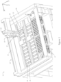
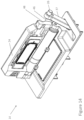
- a slide transport system 10 for an automated slide treatment apparatus 12 for treating tissue samples disposed on slides 13 is shown in Figure 1 .
- the slide treatment apparatus 12 includes a plurality of slide treatment modules 14 arranged to receive the slides 13, and includes at least one fluid dispensing robot 16 configured by a controller (not shown) to dispense a plurality of reagents to the slides in the slide treatment modules 14 to treat tissue samples on the slides and a slide transport robot 18 configured by the controller to move the slides 13 to and from the slide treatment modules 14.
- the controller of the automated slide treatment apparatus 12 - and the slide transport robot 18 and the at least one fluid dispensing robot 16 - can either be implemented remotely from the apparatus 12 (e.g.
- controller implemented by a computer remote from the apparatus) or can be implemented locally with respect to the apparatus 12.
- more than one controller can be employed by the apparatus 12; for example, a controller for the fluid dispensing robot 16 and the slide transport robot 18.
- the controller includes a number of modules, implemented by a processor and a memory for storing instructions for the modules, to provide instructions to the slide transport robot 18 and the at least one fluid dispensing robot 16 to control movement thereof and dispensing of reagents.
- the slide transport robot 18 is a gantry robot configured by the controller to move the slides 13 to and from the slide treatment modules 14.
- the slide transport robot 18 is combined with a fluid dispensing robot 16 in the gantry robot, which is configured to move in the x, y and z axes.
- the slide transport robot 18 can be independent from the fluid dispensing robot 16.
- the slide transport robot 18 can be an articulated armed robot while the fluid dispensing robot 16 can be a gantry robot, and vice versa.
- the fluid dispensing robot 16 is a fluid transfer probe (FTP) robot configured by the controller to dispense a plurality of high value reagents stored in reagent containers (not shown) to the slides 13 in the slide treatment modules 14.
- high value reagents include chromogens and antibodies.
- the gantry robot includes the combined FTP robot 16 and the slide transport robot 18 to minimise the size of the apparatus.
- the x axis is a length of the apparatus 12
- the y axis is a width of the apparatus 12
- the z axis corresponds to a height of the apparatus 12.
- the slide transport robot 18 is configured by the controller to move quickly between the different modules in the apparatus 12 in the three axes so as to efficiently move slides in and out of the slide treatment modules 14 so as to treat samples disposed on the slides in the slide treatment modules 14.
- the slide transport robot 18 is configured to move from one corner of the apparatus 12 to the diagonally opposite corner in 2.2 seconds (which represents the maximum move with respect to the apparatus 12).
- the travel profiles for the example of the slide transport robot 18 shown with respect to the apparatus 12 in Figure 1 are: 780 mm in the x axis, 500 mm in the y axis and 120 mm in the z axis although these ranges are examples only.
- the gantry robot 18 and the FTP robot 16 moves along a rail 21 in the x direction and a rail 19 in the y direction so as to move slides to and from the slide treatment modules 14 so as to dispense a plurality of reagents to the slides received in the slide treatment modules 14.
- the apparatus 12 includes two bulk fluid robots (BFRs) 15 to dispense high volume reagents and the FTP robot 16 to dispense low volume reagents. That is, the BFRs 15 are configured by the controller to dispense a plurality of lesser value reagents (e.g. bulk or high volume reagents) stored in reagent containers to the slides 13 received in the slide treatment modules 14 to also treat tissue samples on the slides 13. That is, in some cases, to treat the tissue samples on the slides 13, a designated combination and order of high and lesser value, bulk reagents is dispensed to the slide. It will be appreciated by those persons skilled in the art that the apparatus 12 may include more than two BFRs to dispense the lesser value reagents stored in reagent containers to the slides 13.
- BFRs bulk fluid robots
- the BFRs 15 are configured by the controller to dispense bulk reagents to the slides 13, such as solutions of oxalic acid, sulphuric acid, potassium permanganate, alcohol, dewaxing agent, dyes such as haematoxylin, peroxide, distilled water and buffer to treat the tissue samples disposed thereon.
- bulk reagents such as solutions of oxalic acid, sulphuric acid, potassium permanganate, alcohol, dewaxing agent, dyes such as haematoxylin, peroxide, distilled water and buffer to treat the tissue samples disposed thereon.
- the slide transport robot 18 is configured to move the slides 13 to and from the slide treatment modules 14 without interfering with the BFRs 15 as the slide transport robot 18 can move in the z direction.
- the BFRs 15 are configured to move only in two directions, (the x and z directions shown) to dispense the bulk reagents to the slides 13 in the slide treatment modules 14.
- the slide transport system 10 also includes a slide transport device 20, shown in say Figure 5 , disposed on the slide transport robot 18, which is configured by the controller to releasably hold the slides 13.
- the slide transport device 20 includes a suction cup arranged to releasably hold the slide 13 when it is to be moved to a slide treatment module 14 and to release the slide 13 to locate it in the slide treatment module 14.
- the slide transport device 20 is envisaged to include other means for releasably holding a slide, such as a gripper.
- the slide transport robot 18 includes a slide handling head 22 arranged to move a closure body 24, shown in more detail in Figure 5 , of one of the slide treatment modules 14 so as to move the closure body 24 normally biased in a closed position to an open position when the slide transport robot is configured by the controller to move one of the slides 13 to the slide treatment module 14.
- the slide transport device 20 is then configured by the controller to release the slide 13 so as to locate the slide 13 in the slide treatment module 14 when the closure body 24 is in the open position (as shown more clearly in Figure 5 ).
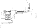
- Figures 1 and 2 also show the automated slide treatment apparatus 12 having input and output buffers in the form of an access module 17, whereby the input buffer of the access module 17 introduces slides 13 to the apparatus 12 for treatment and the output buffer of the access module 17 allows for the removal of the slides 13 from the apparatus 12 after treatment of the tissue samples on the slides 13.
- the slide transport robot 18 of the embodiment is thus further configured to retrieve a slide from the access module 17 and locate it in a slide treatment module 14 and to remove the slide 13 from the slide treatment module 14 and locate it in the access module 17 after the tissue samples disposed on the slide have been treated.
- the slide transport robot 18 of the embodiment can also be configured to move the slide to/from other modules (not shown) for performing other operations on the slide, such as coverslipping and digital imaging modules, before moving the slide 13 to the access module 17.
- a calibration module which calibrates the position of the slide treatment robot 18 within the automated slide treatment apparatus 12.
- the calibration module is disposed at a known location in the automated slide treatment apparatus 12 with known x, y and z coordinates so that the slide treatment robot 18 can calibrate its perceived location with the actual location at designated time intervals.
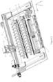
- FIGS 3 and 4 show the slide transport robot 18 in further detail.
- the slide transport robot 18 is configured to move along the rail 21 in the x axis and along a rack 23, of a rack and pinion drive system, in the z axis so as to locate a slide 13 in the slide treatment module 14 when the closure body 24, shown in Figure 5 , is held in the open position by the slide handling head 22.
- the rack 23 is driven by a pinion on the robot 18 to lower and raise the slide 13 in the z axis.
- the slide transport robot 18 moves along the rail 21 and the rail 19 in the x and y axes, as shown in Figure 2 , using a chain drive system driven by stepper motors. Nonetheless, it will be appreciated by those persons skilled in the art that other drive systems may be employed, such as another further rack and pinion or belt drive system, pneumatic, solenoid, or lead screw systems.
- the FTP robot 16 is also shown in more detail, in Figures 3 and 4 , which is combined with the slide transport robot 18.
- the FTP robot 16 is configured to move in the x axis using the above described chain drive system and to dispense the reagents to the slide 13 in the slide treatment module 14 (not shown) with a probe 25.
- the probe 25 can be raised or lowered in the z axis by another rack and pinion drive system 35 so that the reagents can be dispensed to the slide 13 when the closure body 24 of the slide treatment module 14 is in the closed position.
- the probe 25 and the slide transport device 20 can be raised or lowered in the z axis by the same drive mechanism.
- the FTP robot 16 is described in more detail in the co-pending US provisional patent application 61/721,269 entitled "A Fluid Transport System", having a filing date of 1 November 2012 .
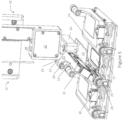
- Figures 5 and 6A-C show a snapshot of the slide treatment apparatus 12 in use.
- they show the slide transport robot 18 of the slide transport system 10 engaging with the slide treatment module 14 to locate a slide 13 in the slide treatment module 14 for dispensing of reagents and thus treatment of tissue samples on the slide 13.
- the slide handling head 22 of the slide transport robot 18 is arranged to contact against a bearing surface 26 of the closure body 24 to move the closure body 24 to the open position. More particularly, it can be seen that the slide handling head 22 contacts against the bearing surface 26 when the slide transport robot 18 moves in the x axis to move the closure body 24 to the open position.
- the slide treatment modules 14 are aligned in the apparatus 12 so as to be opened in the x direction to minimise the amount of movement for the slide transport robot 18.
- the slide handling head 22 of the slide transport robot 18 contacts against the bearing surface 26 of the closure body 24 to pivot the closure body 24 about a pivot 30 to the open position.
- the closure body 24 is biased to the closed position with a spring 27 so that the slide handling head 22 contacts against the bearing surface 26 of the closure body 24 of the slide treatment module 14 whilst the bias of the closure body 24 urges it to the closed position both when the slide transport robot 18 moves in the x direction to locate the slide 13 in the slide treatment module 14 and when the slide transport robot 18 removes the slide from the slide treatment module 14.
- the slide transport robot 18 further moves in the x and y axes when the closure body 24 is in the open position to further (e.g. better) locate the slide 13 in the slide treatment module 14 using at least one reference datum point 28 disposed on the slide treatment module 14. That is, the slide transport robot 18 stops moving the slide 13 in the slide treatment module in the x and/or y axes when the slide touches the reference data points 28.
- the slide treatment module 14 includes a mounting surface 29 (e.g. floor) of the slide treatment module 14 and the slide transport robot 18 stops moving the slide 13 in the slide treatment module in the z axes when the slide 13 touches the mounting surface 29.
- the spring 27 can also bias the closure body 24 to the closed position to achieve a seal with the slide 13 and the mounting surface 29 to create a sealed reaction chamber - for example, substantially the size of the slide - for treating the tissue samples on the slide 13 with the use of a cover member 31 of the slide treatment module 14.
- the cover member 31 is disposed on the underside of the closure body 24 and is arranged to form the sealed reaction chamber with the slide 13 when the closure body 24 is in the closed position after the slide transport robot 18 has located the slide 13 in the slide treatment module 14. Details of the cover member is described in the co-pending US provisional patent application 61/721,280 entitled "Slide Staining Assembly and Cover Member", having a filing date of 1 November 2012 .
- the FTP robot 16 and the BFR 15 can then dispense reagents to the slide 13 in the slide treatment module 14 when the closure body 24 is in the closed position in the designated order and with designated volumes. It will be appreciated by those persons skilled in the art that the instructions and the order can be stored in a memory in data communication with the controller.
- the instructions, or at least part thereon are stored on each of the slides 13 in the form of a label that is read by an indicia reader 44, as shown in Figures 7 and 8 (showing a light path extending from the indicia reader 44).
- the slide handling head 22 includes the indicia reader 44 which is disposed at an angle to the slide handling head 22 and is configured to read labels disposed on the slides 13 to receive information indicative of instructions for the controller to treat the tissue samples disposed on the corresponding slides.
- the label will include complete instructions to treat samples disposed on the slides and, in some other cases, it will contain part instructions or a link to stored instructions for the controller to implement the method of treatment.
- the indicia reading device 44 acquires data, such as Label ID, liquid level sensor information, reagent IDs and calibration data, from a label in for form of, say, a 1D, 2D or 3D barcode, or an RFID, OCR or integrated circuit disposed on the slide 13.
- data includes protocol information, sample/case ID, and pathologist/other lab information.
- the closure body 24 and the slide transport robot 18 are arranged so that movement of the slide transport robot 18 opens and closes the closure body 24 of the slide treatment module 14.
- the bearing surface 26 of the closure body 24 includes a cam roller 32 protruding from the closure body 24 at a distal end of an arm 33 protruding from the closure body 24.
- the slide handling head 22 of the slide transport robot 18 includes a protruding contact member 34 arranged to contact the cam roller 32 to move the closure body 24 to the open position.
- the slide handling head 22 of the slide transport robot 18 contacts against the bearing surface 26 of the closure body 24 of a slide treatment module 14 to pivot the closure body 24 about the pivot 30 to the open position and back to the closed position after locating or removing a slide therein.
- the cam roller 32 protrudes from the closure body 24 to define a gap bordered on two sides corresponding (at least partially) in shape to the protruding contact member 34 of the slide handling head 22.
- the slide transport device 20, including the suction cup and associated suction mechanism, also protrudes from the slide handling head 22 adjacent the protruding contact member 34 and is spaced apart from the protruding contact member 34 so as to provide a gap 36 there between, shown most clearly in in Figure 6A .
- one end 38 of the closure body extends into the gap 36 between the spaced apart protruding contact member 34 and the slide transport device 20, and part of the protruding contact member 34 extends into the gap provided between the arm 33 and the cam roller 32.
- the slide transport robot 18 is located adjacent a first slide treatment module 14A for a slide 13 to be located therein, and then, in Figure 6B , the robot 18 moves the slide 13 in the x axis to locate it in the slide treatment module 14A by pivoting the closure body 24 about the pivot 30 to an open position.
- the slide transport robot 18 then moves in the z axis to lower the slide 13 in the slide treatment module 14A so that the slide transport device 20 (e.g. suction cup) can release the slide 13 so as to locate it in the slide treatment module 14A for subsequent treatment.
- the slide transport device 20 e.g. suction cup
- the protruding slide transport device 20 and the protruding contact member 34 of the slide handling head 22 correspond in size to a slide treatment module 14B. That is, the protruding portions of the slide handling head 22 fit between adjacent cam rollers 32 and protruding arms of the slide treatment modules 14A and 14B so as to maximise the number of slide treatment modules 14 that can be implemented by the apparatus 12. In this way, the slide handling head 22 of the slide transport robot 18 can be located above the slide treatment module 14B adjacent to the slide treatment module 14A before moving the slide treatment module 14A to the open position to locate a slide therein.
- the slide transport device 20 includes a suction cup 40, as shown in Figure 9 .
- the slide transport device 20 is a bellowed suction cup 42, which allows for the further application of friction, contained in a housing 43.
- the suction cups 40 or 42 may be made from a material such as polymeric, elastomeric or plastic material such as nitrile, polyurethane or viton and it can be seen that the suction cup 40 may include internal cleats 45 to ensure the slide is held in place.
- the bellowed suction cup 42 includes a vacuum means (not shown in the Figures) for activating the cup that is configured by the controller to releasably hold the slides 13.
- the suction cup 40 can also be implemented with respect to the vacuum means or it may simply use its cavity and applied pressure to displace air to releasably hold a slide.
- the vacuum means may be configured to operate with the use of pressure sensors to maintain pressure and thus grip on the slides.
- the vacuum means maintains a positive pressure to avoid the slide sticking to the bellow suction cup 42.
- the slide transport device 20 may include additional sensors (not shown), such as an optical sensor or a reflective optoelectronic sensor, for checking whether a slide being held is in the correct position for it to be located accordingly.
- Figures 12 and 13 show a further embodiment of the slide transport system 10 where the closure body 24 is detained in the closed position with a detent 46 protruding from a detention arm 37 that is arranged to cooperate with a recess 48 in the closure body 24 in the closed position. Accordingly, the closure body 24 can be detained in the closed position against the action of an opening bias or it can be detained to prevent accidental opening of the closure body 24 of the slide treatment module 14.
- the slide treatment module 24 includes two opposing biasing means. Specifically, an opening biasing means 52 for applying biasing force to the closure body 24 to pivot the closure body 24 to the open position and a larger, closing biasing means 50 for applying biasing force to the closure body 24 to pivot the closure body 24 to the closed position. As shown, the biasing means are springs and, for example, the opening biasing means 52 applies a force of approximately 5N and the closing biasing means 50 applies a closing force of approximately 45N.
- the bearing surface 26 is disposed at one end of the detention arm 37 so that the slide handling head 22, specifically the protruding contact member 34 of the slide handling head 22, contacts against the bearing surface 26 to move the closure body 24 to the open position.
- the bearing surface 26 includes the cam roller 32 described above at one of its ends.
- the protruding contact member 34 contacts against the cam roller 32 to release the recess 48 of the closure body 24 from the detent 46 so as to pivot the closure body 24 to the open position about the pivot 30 disposed on the slide treatment module 14.
- Action of the the slide handling head 22 of the slide transport robot 18, after releasing the detent 46 therefore pivots the closure body 24 about the pivot 30 to the open position and back to the closed position after locating or removing a slide therein as described above.
- Figures 13 and 14 show the detention arm 37 in further detail.
- the detention arm 37 includes a detention pivot 54 at an opposed end to the cam roller 32 that is retained by a section of the slide treatment module 14.
- the detention arm 37 rotates about detention pivot 54 as it is moved by the slide handing head 22 between the open and closed positions of the closure body 24.
- Figure 13 shows the detention arm 37 in the closed position with the detent 46 within the recess 48 (not shown in the Figure).
- Figure 14 shows the detention arm 37 in the open position with the detent 46 disengaged from the recess 48.
- the action of the slide handling head 22 rotates the detention arm 37 around detention pivot 54 so that the end with the detent 46 tracks along the top of the closure body 24 to its open position and the closure body 24 is consequently moved to the open position to an angle determined by the angle of the endstop 56. It will be appreciated that, in the open position, the detent 46 is moved away from the recess 48 of the closure body 24.
- movement means other than biasing means can be employed by the slide transport system 10 to open and close the closure body 24 of the slide treatment module 14.
- a motor (not shown) may drive the closure body 24 to the open position until reaching its final position that is bound by the movement of the detention arm 37.
- the motor may also drive the closure body 24 back to the closed position.
- the motor is a screw drive motor.
- the detent 46 is an electromagnetic detent that is configured to detain the closure body 24 in the closed position when say a current is applied.
- the electromagnetic detent can be released by the slide handling head 22 moving against the cam roller 32 to open the current circuit.
- the method includes the steps of releasably holding 102 slides with a slide transport device disposed at one end of a slide transport robot, moving 104 the slides to and from slide treatment modules with the slide transport robot, whereby the slide treatment modules receive the slides and reagents are dispensed to the slides in the modules to treat one or more tissue samples disposed on the slides, moving 106 a slide handling head of the slide transport robot to move a closure body of one of the slide treatment modules normally held in a closed position to an open position when the slide transport robot moves one of the slides to the slide treatment module, and releasing 108 said one of the slides so as to locate the slide in the slide treatment module when the closure body is in the open position.
Landscapes
- Life Sciences & Earth Sciences (AREA)
- Health & Medical Sciences (AREA)
- General Health & Medical Sciences (AREA)
- Chemical & Material Sciences (AREA)
- Analytical Chemistry (AREA)
- Biochemistry (AREA)
- Physics & Mathematics (AREA)
- General Physics & Mathematics (AREA)
- Immunology (AREA)
- Pathology (AREA)
- Engineering & Computer Science (AREA)
- Robotics (AREA)
- Biomedical Technology (AREA)
- Molecular Biology (AREA)
- Sampling And Sample Adjustment (AREA)
Applications Claiming Priority (2)
| Application Number | Priority Date | Filing Date | Title |
|---|---|---|---|
| US201261721257P | 2012-11-01 | 2012-11-01 | |
| PCT/AU2013/001263 WO2014066946A1 (en) | 2012-11-01 | 2013-11-01 | A slide transport system |
Publications (3)
| Publication Number | Publication Date |
|---|---|
| EP2914948A1 EP2914948A1 (en) | 2015-09-09 |
| EP2914948A4 EP2914948A4 (en) | 2016-07-06 |
| EP2914948B1 true EP2914948B1 (en) | 2024-10-09 |
Family
ID=50626220
Family Applications (1)
| Application Number | Title | Priority Date | Filing Date |
|---|---|---|---|
| EP13851009.4A Active EP2914948B1 (en) | 2012-11-01 | 2013-11-01 | A slide transport system |
Country Status (6)
Families Citing this family (21)
| Publication number | Priority date | Publication date | Assignee | Title |
|---|---|---|---|---|
| WO2014066947A1 (en) * | 2012-11-01 | 2014-05-08 | Leica Biosystems Melbourne Pty Ltd | A fluid transport system |
| WO2015197742A1 (en) * | 2014-06-27 | 2015-12-30 | Ventana Medical Systems, Inc. | Automated specimen processing systems and methods of detecting specimen-bearing microscope slides |
| SG11201700483UA (en) * | 2014-07-28 | 2017-02-27 | Douglas Scient Llc | Instrument for analyzing biological samples and reagents |
| CN116046500A (zh) * | 2016-04-28 | 2023-05-02 | 希森美康株式会社 | 样本涂抹装置 |
| CN106706398B (zh) * | 2017-02-08 | 2024-06-07 | 爱威科技股份有限公司 | 一种样本染色装置 |
| US12392692B2 (en) | 2017-03-09 | 2025-08-19 | Hologic, Inc. | Systems for automated preparation of biological specimens |
| JP6934061B2 (ja) * | 2017-03-09 | 2021-09-08 | ホロジック, インコーポレイテッドHologic, Inc. | 生物学的検体の自動調製システム及び方法 |
| CN106840819A (zh) * | 2017-04-11 | 2017-06-13 | 郭秋婷 | 玻片支撑夹及玻片染色架 |
| US10368467B2 (en) * | 2017-10-10 | 2019-07-30 | Facebook, Inc. | System and method for data center heat containment |
| JP7289288B2 (ja) * | 2017-12-21 | 2023-06-09 | ライカ・バイオシステムズ・メルボルン・プロプライエタリー・リミテッド | 流体輸送システム |
| CN108088726B (zh) * | 2018-02-08 | 2020-12-22 | 爱威科技股份有限公司 | 一种多功能任选染色装置 |
| US10589423B2 (en) * | 2018-06-18 | 2020-03-17 | Shambhu Nath Roy | Robot vision super visor for hybrid homing, positioning and workspace UFO detection enabling industrial robot use for consumer applications |
| CN109387419B (zh) * | 2018-12-05 | 2024-06-28 | 滨州医学院 | 一种切片制作染色与扫描一体机 |
| EP3841386A4 (en) * | 2018-12-20 | 2021-10-20 | Leica Biosystems Melbourne Pty Ltd | BLADE TRAY SET |
| US11193950B2 (en) * | 2019-03-29 | 2021-12-07 | Sakura Finetek U.S.A., Inc. | Slide identification sensor |
| CN110132694A (zh) * | 2019-05-27 | 2019-08-16 | 福州迈新生物技术开发有限公司 | 一种全自动病理染色系统降低故障二次损坏的方法 |
| KR102848024B1 (ko) * | 2019-12-17 | 2025-08-21 | 베크만 컬터, 인코포레이티드 | 컴퓨터 구현 액체 핸들러 프로토콜 |
| CN111539998B (zh) * | 2020-05-07 | 2021-03-12 | 姚远 | 一种病理数据载体及其管理系统 |
| CN114505293B (zh) * | 2022-03-24 | 2022-12-23 | 山东第一医科大学(山东省医学科学院) | 一种自动化载玻片清洗装置 |
| CN117074135B (zh) * | 2023-08-21 | 2024-03-19 | 安徽麦吉恩医疗科技有限公司 | 一种高效率临床医学检验涂片设备 |
| WO2025042527A1 (en) * | 2023-08-22 | 2025-02-27 | Agilent Technologies, Inc. | Systems and methods for transporting slides |
Citations (1)
| Publication number | Priority date | Publication date | Assignee | Title |
|---|---|---|---|---|
| US20070172396A1 (en) * | 2006-01-23 | 2007-07-26 | Neeper Robert K | Automated system for storing, retrieving and managing sample |
Family Cites Families (6)
| Publication number | Priority date | Publication date | Assignee | Title |
|---|---|---|---|---|
| US5039615A (en) * | 1987-04-11 | 1991-08-13 | Kabushiki Kaisha Kyoto Daiichi Kagaku | Method for chemically analyzing a test piece |
| US6739448B1 (en) * | 2000-02-01 | 2004-05-25 | Incyte Corporation | Method and apparatus for shuttling microtitre plates |
| CN100507496C (zh) * | 2002-06-20 | 2009-07-01 | 视觉生物体系有限公司 | 带有排放机构的生物反应装置及方法 |
| US7657070B2 (en) * | 2006-01-20 | 2010-02-02 | Sakura Finetek U.S.A., Inc. | Automated system of processing biological specimens and method |
| US8877485B2 (en) | 2009-12-09 | 2014-11-04 | Dako Denmark A/S | Apparatus and method for processing biological samples |
| WO2012064873A1 (en) * | 2010-11-10 | 2012-05-18 | Constitution Medical, Inc. | Automated systems and methods for preparing biological specimens for examination |
-
2013
- 2013-11-01 WO PCT/AU2013/001263 patent/WO2014066946A1/en active Application Filing
- 2013-11-01 US US14/439,788 patent/US9927332B2/en active Active
- 2013-11-01 EP EP13851009.4A patent/EP2914948B1/en active Active
- 2013-11-01 AU AU2013337607A patent/AU2013337607B2/en active Active
- 2013-11-01 JP JP2015540000A patent/JP6215336B2/ja active Active
- 2013-11-01 CN CN201380069045.8A patent/CN104884930B/zh active Active
Patent Citations (1)
| Publication number | Priority date | Publication date | Assignee | Title |
|---|---|---|---|---|
| US20070172396A1 (en) * | 2006-01-23 | 2007-07-26 | Neeper Robert K | Automated system for storing, retrieving and managing sample |
Also Published As
| Publication number | Publication date |
|---|---|
| EP2914948A4 (en) | 2016-07-06 |
| AU2013337607A1 (en) | 2015-05-21 |
| CN104884930B (zh) | 2017-11-14 |
| JP6215336B2 (ja) | 2017-10-18 |
| US20150300931A1 (en) | 2015-10-22 |
| JP2015533417A (ja) | 2015-11-24 |
| WO2014066946A1 (en) | 2014-05-08 |
| US9927332B2 (en) | 2018-03-27 |
| AU2013337607B2 (en) | 2017-03-09 |
| CN104884930A (zh) | 2015-09-02 |
| EP2914948A1 (en) | 2015-09-09 |
Similar Documents
| Publication | Publication Date | Title |
|---|---|---|
| EP2914948B1 (en) | A slide transport system | |
| US20210239582A1 (en) | System and method for the automated preparation of biological samples | |
| AU2003287895B2 (en) | Method and apparatus for pretreatment of biological samples | |
| EP2938994B1 (en) | Specimen processing systems and methods for aligning slides | |
| JP6047243B2 (ja) | 自動標本処理システムおよびその使用方法 | |
| CA2745561C (en) | Automated system and method of processing biological specimens | |
| JP6117937B2 (ja) | 標本処理システムおよびスライドガラスを均一に加熱する方法 | |
| US20210293672A1 (en) | Automated specimen processing systems and methods | |
| AU2020418169B2 (en) | Automated staining system and reaction chamber | |
| US20240246085A1 (en) | Sample processing assembly | |
| JP6117936B2 (ja) | 標本処理システムおよび蒸発を抑える方法 | |
| US10816443B2 (en) | Automated batch stainer for immunohistochemistry | |
| EP4609207A1 (en) | A sample carrier transport device |
Legal Events
| Date | Code | Title | Description |
|---|---|---|---|
| PUAI | Public reference made under article 153(3) epc to a published international application that has entered the european phase |
Free format text: ORIGINAL CODE: 0009012 |
|
| 17P | Request for examination filed |
Effective date: 20150508 |
|
| AK | Designated contracting states |
Kind code of ref document: A1 Designated state(s): AL AT BE BG CH CY CZ DE DK EE ES FI FR GB GR HR HU IE IS IT LI LT LU LV MC MK MT NL NO PL PT RO RS SE SI SK SM TR |
|
| AX | Request for extension of the european patent |
Extension state: BA ME |
|
| DAX | Request for extension of the european patent (deleted) | ||
| RA4 | Supplementary search report drawn up and despatched (corrected) |
Effective date: 20160603 |
|
| RIC1 | Information provided on ipc code assigned before grant |
Ipc: G01N 1/31 20060101ALI20160530BHEP Ipc: G01N 35/10 20060101ALN20160530BHEP Ipc: G01N 35/00 20060101ALI20160530BHEP Ipc: G01N 1/28 20060101AFI20160530BHEP |
|
| STAA | Information on the status of an ep patent application or granted ep patent |
Free format text: STATUS: EXAMINATION IS IN PROGRESS |
|
| 17Q | First examination report despatched |
Effective date: 20190705 |
|
| GRAP | Despatch of communication of intention to grant a patent |
Free format text: ORIGINAL CODE: EPIDOSNIGR1 |
|
| STAA | Information on the status of an ep patent application or granted ep patent |
Free format text: STATUS: GRANT OF PATENT IS INTENDED |
|
| RIC1 | Information provided on ipc code assigned before grant |
Ipc: G01N 35/10 20060101ALN20240704BHEP Ipc: G01N 1/31 20060101ALI20240704BHEP Ipc: G01N 35/00 20060101ALI20240704BHEP Ipc: G01N 1/28 20060101AFI20240704BHEP |
|
| INTG | Intention to grant announced |
Effective date: 20240719 |
|
| GRAS | Grant fee paid |
Free format text: ORIGINAL CODE: EPIDOSNIGR3 |
|
| GRAA | (expected) grant |
Free format text: ORIGINAL CODE: 0009210 |
|
| STAA | Information on the status of an ep patent application or granted ep patent |
Free format text: STATUS: THE PATENT HAS BEEN GRANTED |
|
| P01 | Opt-out of the competence of the unified patent court (upc) registered |
Free format text: CASE NUMBER: APP_45820/2024 Effective date: 20240807 |
|
| AK | Designated contracting states |
Kind code of ref document: B1 Designated state(s): AL AT BE BG CH CY CZ DE DK EE ES FI FR GB GR HR HU IE IS IT LI LT LU LV MC MK MT NL NO PL PT RO RS SE SI SK SM TR |
|
| REG | Reference to a national code |
Ref country code: GB Ref legal event code: FG4D |
|
| REG | Reference to a national code |
Ref country code: CH Ref legal event code: EP |
|
| REG | Reference to a national code |
Ref country code: DE Ref legal event code: R096 Ref document number: 602013086169 Country of ref document: DE |
|
| REG | Reference to a national code |
Ref country code: IE Ref legal event code: FG4D |
|
| PGFP | Annual fee paid to national office [announced via postgrant information from national office to epo] |
Ref country code: DE Payment date: 20241023 Year of fee payment: 12 |
|
| PGFP | Annual fee paid to national office [announced via postgrant information from national office to epo] |
Ref country code: GB Payment date: 20241017 Year of fee payment: 12 |
|
| PGFP | Annual fee paid to national office [announced via postgrant information from national office to epo] |
Ref country code: FR Payment date: 20241021 Year of fee payment: 12 |
|
| REG | Reference to a national code |
Ref country code: LT Ref legal event code: MG9D |
|
| REG | Reference to a national code |
Ref country code: NL Ref legal event code: MP Effective date: 20241009 |
|
| REG | Reference to a national code |
Ref country code: AT Ref legal event code: MK05 Ref document number: 1731053 Country of ref document: AT Kind code of ref document: T Effective date: 20241009 |
|
| PG25 | Lapsed in a contracting state [announced via postgrant information from national office to epo] |
Ref country code: NL Free format text: LAPSE BECAUSE OF FAILURE TO SUBMIT A TRANSLATION OF THE DESCRIPTION OR TO PAY THE FEE WITHIN THE PRESCRIBED TIME-LIMIT Effective date: 20241009 |
|
| PG25 | Lapsed in a contracting state [announced via postgrant information from national office to epo] |
Ref country code: NL Free format text: LAPSE BECAUSE OF FAILURE TO SUBMIT A TRANSLATION OF THE DESCRIPTION OR TO PAY THE FEE WITHIN THE PRESCRIBED TIME-LIMIT Effective date: 20241009 |
|
| PG25 | Lapsed in a contracting state [announced via postgrant information from national office to epo] |
Ref country code: IS Free format text: LAPSE BECAUSE OF FAILURE TO SUBMIT A TRANSLATION OF THE DESCRIPTION OR TO PAY THE FEE WITHIN THE PRESCRIBED TIME-LIMIT Effective date: 20250209 Ref country code: HR Free format text: LAPSE BECAUSE OF FAILURE TO SUBMIT A TRANSLATION OF THE DESCRIPTION OR TO PAY THE FEE WITHIN THE PRESCRIBED TIME-LIMIT Effective date: 20241009 Ref country code: PT Free format text: LAPSE BECAUSE OF FAILURE TO SUBMIT A TRANSLATION OF THE DESCRIPTION OR TO PAY THE FEE WITHIN THE PRESCRIBED TIME-LIMIT Effective date: 20250210 |
|
| PG25 | Lapsed in a contracting state [announced via postgrant information from national office to epo] |
Ref country code: FI Free format text: LAPSE BECAUSE OF FAILURE TO SUBMIT A TRANSLATION OF THE DESCRIPTION OR TO PAY THE FEE WITHIN THE PRESCRIBED TIME-LIMIT Effective date: 20241009 |
|
| PG25 | Lapsed in a contracting state [announced via postgrant information from national office to epo] |
Ref country code: BG Free format text: LAPSE BECAUSE OF FAILURE TO SUBMIT A TRANSLATION OF THE DESCRIPTION OR TO PAY THE FEE WITHIN THE PRESCRIBED TIME-LIMIT Effective date: 20241009 |
|
| PG25 | Lapsed in a contracting state [announced via postgrant information from national office to epo] |
Ref country code: ES Free format text: LAPSE BECAUSE OF FAILURE TO SUBMIT A TRANSLATION OF THE DESCRIPTION OR TO PAY THE FEE WITHIN THE PRESCRIBED TIME-LIMIT Effective date: 20241009 |
|
| PG25 | Lapsed in a contracting state [announced via postgrant information from national office to epo] |
Ref country code: NO Free format text: LAPSE BECAUSE OF FAILURE TO SUBMIT A TRANSLATION OF THE DESCRIPTION OR TO PAY THE FEE WITHIN THE PRESCRIBED TIME-LIMIT Effective date: 20250109 |
|
| PG25 | Lapsed in a contracting state [announced via postgrant information from national office to epo] |
Ref country code: LV Free format text: LAPSE BECAUSE OF FAILURE TO SUBMIT A TRANSLATION OF THE DESCRIPTION OR TO PAY THE FEE WITHIN THE PRESCRIBED TIME-LIMIT Effective date: 20241009 Ref country code: AT Free format text: LAPSE BECAUSE OF FAILURE TO SUBMIT A TRANSLATION OF THE DESCRIPTION OR TO PAY THE FEE WITHIN THE PRESCRIBED TIME-LIMIT Effective date: 20241009 Ref country code: GR Free format text: LAPSE BECAUSE OF FAILURE TO SUBMIT A TRANSLATION OF THE DESCRIPTION OR TO PAY THE FEE WITHIN THE PRESCRIBED TIME-LIMIT Effective date: 20250110 |
|
| PG25 | Lapsed in a contracting state [announced via postgrant information from national office to epo] |
Ref country code: PL Free format text: LAPSE BECAUSE OF FAILURE TO SUBMIT A TRANSLATION OF THE DESCRIPTION OR TO PAY THE FEE WITHIN THE PRESCRIBED TIME-LIMIT Effective date: 20241009 |
|
| PG25 | Lapsed in a contracting state [announced via postgrant information from national office to epo] |
Ref country code: RS Free format text: LAPSE BECAUSE OF FAILURE TO SUBMIT A TRANSLATION OF THE DESCRIPTION OR TO PAY THE FEE WITHIN THE PRESCRIBED TIME-LIMIT Effective date: 20250109 |
|
| REG | Reference to a national code |
Ref country code: CH Ref legal event code: PL |
|
| PG25 | Lapsed in a contracting state [announced via postgrant information from national office to epo] |
Ref country code: SM Free format text: LAPSE BECAUSE OF FAILURE TO SUBMIT A TRANSLATION OF THE DESCRIPTION OR TO PAY THE FEE WITHIN THE PRESCRIBED TIME-LIMIT Effective date: 20241009 |
|
| PG25 | Lapsed in a contracting state [announced via postgrant information from national office to epo] |
Ref country code: MC Free format text: LAPSE BECAUSE OF FAILURE TO SUBMIT A TRANSLATION OF THE DESCRIPTION OR TO PAY THE FEE WITHIN THE PRESCRIBED TIME-LIMIT Effective date: 20241009 |
|
| PG25 | Lapsed in a contracting state [announced via postgrant information from national office to epo] |
Ref country code: DK Free format text: LAPSE BECAUSE OF FAILURE TO SUBMIT A TRANSLATION OF THE DESCRIPTION OR TO PAY THE FEE WITHIN THE PRESCRIBED TIME-LIMIT Effective date: 20241009 |
|
| REG | Reference to a national code |
Ref country code: DE Ref legal event code: R097 Ref document number: 602013086169 Country of ref document: DE |
|
| PG25 | Lapsed in a contracting state [announced via postgrant information from national office to epo] |
Ref country code: LU Free format text: LAPSE BECAUSE OF NON-PAYMENT OF DUE FEES Effective date: 20241101 |
|
| REG | Reference to a national code |
Ref country code: CH Ref legal event code: PL |
|
| PG25 | Lapsed in a contracting state [announced via postgrant information from national office to epo] |
Ref country code: EE Free format text: LAPSE BECAUSE OF FAILURE TO SUBMIT A TRANSLATION OF THE DESCRIPTION OR TO PAY THE FEE WITHIN THE PRESCRIBED TIME-LIMIT Effective date: 20241009 |
|
| PG25 | Lapsed in a contracting state [announced via postgrant information from national office to epo] |
Ref country code: CH Free format text: LAPSE BECAUSE OF NON-PAYMENT OF DUE FEES Effective date: 20241130 |
|
| PG25 | Lapsed in a contracting state [announced via postgrant information from national office to epo] |
Ref country code: RO Free format text: LAPSE BECAUSE OF FAILURE TO SUBMIT A TRANSLATION OF THE DESCRIPTION OR TO PAY THE FEE WITHIN THE PRESCRIBED TIME-LIMIT Effective date: 20241009 |
|
| PG25 | Lapsed in a contracting state [announced via postgrant information from national office to epo] |
Ref country code: SK Free format text: LAPSE BECAUSE OF FAILURE TO SUBMIT A TRANSLATION OF THE DESCRIPTION OR TO PAY THE FEE WITHIN THE PRESCRIBED TIME-LIMIT Effective date: 20241009 |
|
| PG25 | Lapsed in a contracting state [announced via postgrant information from national office to epo] |
Ref country code: CZ Free format text: LAPSE BECAUSE OF FAILURE TO SUBMIT A TRANSLATION OF THE DESCRIPTION OR TO PAY THE FEE WITHIN THE PRESCRIBED TIME-LIMIT Effective date: 20241009 |
|
| PG25 | Lapsed in a contracting state [announced via postgrant information from national office to epo] |
Ref country code: IT Free format text: LAPSE BECAUSE OF FAILURE TO SUBMIT A TRANSLATION OF THE DESCRIPTION OR TO PAY THE FEE WITHIN THE PRESCRIBED TIME-LIMIT Effective date: 20241009 |
|
| PLBE | No opposition filed within time limit |
Free format text: ORIGINAL CODE: 0009261 |
|
| STAA | Information on the status of an ep patent application or granted ep patent |
Free format text: STATUS: NO OPPOSITION FILED WITHIN TIME LIMIT |