EP2914376B1 - Capsule comprising phase change material, assembly of capsules and method of forming the capsule - Google Patents
Capsule comprising phase change material, assembly of capsules and method of forming the capsule Download PDFInfo
- Publication number
- EP2914376B1 EP2914376B1 EP13785868.4A EP13785868A EP2914376B1 EP 2914376 B1 EP2914376 B1 EP 2914376B1 EP 13785868 A EP13785868 A EP 13785868A EP 2914376 B1 EP2914376 B1 EP 2914376B1
- Authority
- EP
- European Patent Office
- Prior art keywords
- core
- phase change
- capsule
- change material
- mould
- Prior art date
- Legal status (The legal status is an assumption and is not a legal conclusion. Google has not performed a legal analysis and makes no representation as to the accuracy of the status listed.)
- Active
Links
Images




Classifications
-
- F—MECHANICAL ENGINEERING; LIGHTING; HEATING; WEAPONS; BLASTING
- F28—HEAT EXCHANGE IN GENERAL
- F28D—HEAT-EXCHANGE APPARATUS, NOT PROVIDED FOR IN ANOTHER SUBCLASS, IN WHICH THE HEAT-EXCHANGE MEDIA DO NOT COME INTO DIRECT CONTACT
- F28D20/00—Heat storage plants or apparatus in general; Regenerative heat-exchange apparatus not covered by groups F28D17/00 or F28D19/00
- F28D20/02—Heat storage plants or apparatus in general; Regenerative heat-exchange apparatus not covered by groups F28D17/00 or F28D19/00 using latent heat
- F28D20/023—Heat storage plants or apparatus in general; Regenerative heat-exchange apparatus not covered by groups F28D17/00 or F28D19/00 using latent heat the latent heat storage material being enclosed in granular particles or dispersed in a porous, fibrous or cellular structure
-
- B—PERFORMING OPERATIONS; TRANSPORTING
- B01—PHYSICAL OR CHEMICAL PROCESSES OR APPARATUS IN GENERAL
- B01J—CHEMICAL OR PHYSICAL PROCESSES, e.g. CATALYSIS OR COLLOID CHEMISTRY; THEIR RELEVANT APPARATUS
- B01J13/00—Colloid chemistry, e.g. the production of colloidal materials or their solutions, not otherwise provided for; Making microcapsules or microballoons
- B01J13/02—Making microcapsules or microballoons
- B01J13/04—Making microcapsules or microballoons by physical processes, e.g. drying, spraying
-
- B—PERFORMING OPERATIONS; TRANSPORTING
- B29—WORKING OF PLASTICS; WORKING OF SUBSTANCES IN A PLASTIC STATE IN GENERAL
- B29C—SHAPING OR JOINING OF PLASTICS; SHAPING OF MATERIAL IN A PLASTIC STATE, NOT OTHERWISE PROVIDED FOR; AFTER-TREATMENT OF THE SHAPED PRODUCTS, e.g. REPAIRING
- B29C45/00—Injection moulding, i.e. forcing the required volume of moulding material through a nozzle into a closed mould; Apparatus therefor
- B29C45/14—Injection moulding, i.e. forcing the required volume of moulding material through a nozzle into a closed mould; Apparatus therefor incorporating preformed parts or layers, e.g. injection moulding around inserts or for coating articles
- B29C45/14819—Injection moulding, i.e. forcing the required volume of moulding material through a nozzle into a closed mould; Apparatus therefor incorporating preformed parts or layers, e.g. injection moulding around inserts or for coating articles the inserts being completely encapsulated
-
- C—CHEMISTRY; METALLURGY
- C09—DYES; PAINTS; POLISHES; NATURAL RESINS; ADHESIVES; COMPOSITIONS NOT OTHERWISE PROVIDED FOR; APPLICATIONS OF MATERIALS NOT OTHERWISE PROVIDED FOR
- C09K—MATERIALS FOR MISCELLANEOUS APPLICATIONS, NOT PROVIDED FOR ELSEWHERE
- C09K5/00—Heat-transfer, heat-exchange or heat-storage materials, e.g. refrigerants; Materials for the production of heat or cold by chemical reactions other than by combustion
- C09K5/02—Materials undergoing a change of physical state when used
- C09K5/06—Materials undergoing a change of physical state when used the change of state being from liquid to solid or vice versa
- C09K5/063—Materials absorbing or liberating heat during crystallisation; Heat storage materials
-
- F—MECHANICAL ENGINEERING; LIGHTING; HEATING; WEAPONS; BLASTING
- F28—HEAT EXCHANGE IN GENERAL
- F28D—HEAT-EXCHANGE APPARATUS, NOT PROVIDED FOR IN ANOTHER SUBCLASS, IN WHICH THE HEAT-EXCHANGE MEDIA DO NOT COME INTO DIRECT CONTACT
- F28D20/00—Heat storage plants or apparatus in general; Regenerative heat-exchange apparatus not covered by groups F28D17/00 or F28D19/00
- F28D20/0034—Heat storage plants or apparatus in general; Regenerative heat-exchange apparatus not covered by groups F28D17/00 or F28D19/00 using liquid heat storage material
- F28D20/0039—Heat storage plants or apparatus in general; Regenerative heat-exchange apparatus not covered by groups F28D17/00 or F28D19/00 using liquid heat storage material with stratification of the heat storage material
-
- B—PERFORMING OPERATIONS; TRANSPORTING
- B29—WORKING OF PLASTICS; WORKING OF SUBSTANCES IN A PLASTIC STATE IN GENERAL
- B29K—INDEXING SCHEME ASSOCIATED WITH SUBCLASSES B29B, B29C OR B29D, RELATING TO MOULDING MATERIALS OR TO MATERIALS FOR MOULDS, REINFORCEMENTS, FILLERS OR PREFORMED PARTS, e.g. INSERTS
- B29K2101/00—Use of unspecified macromolecular compounds as moulding material
- B29K2101/12—Thermoplastic materials
-
- F—MECHANICAL ENGINEERING; LIGHTING; HEATING; WEAPONS; BLASTING
- F28—HEAT EXCHANGE IN GENERAL
- F28D—HEAT-EXCHANGE APPARATUS, NOT PROVIDED FOR IN ANOTHER SUBCLASS, IN WHICH THE HEAT-EXCHANGE MEDIA DO NOT COME INTO DIRECT CONTACT
- F28D20/00—Heat storage plants or apparatus in general; Regenerative heat-exchange apparatus not covered by groups F28D17/00 or F28D19/00
- F28D2020/0065—Details, e.g. particular heat storage tanks, auxiliary members within tanks
- F28D2020/0069—Distributing arrangements; Fluid deflecting means
-
- F—MECHANICAL ENGINEERING; LIGHTING; HEATING; WEAPONS; BLASTING
- F28—HEAT EXCHANGE IN GENERAL
- F28D—HEAT-EXCHANGE APPARATUS, NOT PROVIDED FOR IN ANOTHER SUBCLASS, IN WHICH THE HEAT-EXCHANGE MEDIA DO NOT COME INTO DIRECT CONTACT
- F28D20/00—Heat storage plants or apparatus in general; Regenerative heat-exchange apparatus not covered by groups F28D17/00 or F28D19/00
- F28D2020/0065—Details, e.g. particular heat storage tanks, auxiliary members within tanks
- F28D2020/0078—Heat exchanger arrangements
-
- Y—GENERAL TAGGING OF NEW TECHNOLOGICAL DEVELOPMENTS; GENERAL TAGGING OF CROSS-SECTIONAL TECHNOLOGIES SPANNING OVER SEVERAL SECTIONS OF THE IPC; TECHNICAL SUBJECTS COVERED BY FORMER USPC CROSS-REFERENCE ART COLLECTIONS [XRACs] AND DIGESTS
- Y02—TECHNOLOGIES OR APPLICATIONS FOR MITIGATION OR ADAPTATION AGAINST CLIMATE CHANGE
- Y02E—REDUCTION OF GREENHOUSE GAS [GHG] EMISSIONS, RELATED TO ENERGY GENERATION, TRANSMISSION OR DISTRIBUTION
- Y02E60/00—Enabling technologies; Technologies with a potential or indirect contribution to GHG emissions mitigation
- Y02E60/14—Thermal energy storage
-
- Y—GENERAL TAGGING OF NEW TECHNOLOGICAL DEVELOPMENTS; GENERAL TAGGING OF CROSS-SECTIONAL TECHNOLOGIES SPANNING OVER SEVERAL SECTIONS OF THE IPC; TECHNICAL SUBJECTS COVERED BY FORMER USPC CROSS-REFERENCE ART COLLECTIONS [XRACs] AND DIGESTS
- Y10—TECHNICAL SUBJECTS COVERED BY FORMER USPC
- Y10T—TECHNICAL SUBJECTS COVERED BY FORMER US CLASSIFICATION
- Y10T29/00—Metal working
- Y10T29/49—Method of mechanical manufacture
Definitions
- the present invention relates to a capsule, having a core comprising phase changing material (PCM), as well as an assembly of a plurality of such capsules, for use in a buffer, and a production method for manufacturing such capsules or assemblies.
- PCM phase changing material
- the invention is based on the insight that the buffers in heating systems or heat exchange systems, like central heating systems, are usually filled with heat exchange fluids, like water. However, water and other usual heat exchange fluids have a limited heat capacity. According to the inventors of the present invention, it has been reported that phase change materials could be employed to enhance the heat capacity of a buffer, but to date no viable embodiment has been encountered.
- DE-10 2010 025297 relates to use of activated silicon having a solvent and other fluids included therein for the skin, which frees solvents and/or the other fluids into the PCM of the core after having been applied thereon.
- DE-100 58 101 discloses a capsule having a core of PCM to which graphite may be added. Material for the core is supplied through an extruder or injector, which necessarily requires use of a solvent, such as paraffin. The presence of such a solvent fluid inside the core will inhibit a desired behaviour of the PCM in the core for storage of heat therein, as paraffin influences and even affects phase transitions of the PCM.
- US4513053 and EP2119498 relate to use of polypropylene or the like as a coating or skin, wherein a solvent is necessary to be added to a base material for the coating or skin. Such solvent will be freed into the PCM after application of the coating or skin onto the core, where freed solvents or other fluids will affect the heat storing capacity or phase changing ability of the core material.
- a capsule according to claim 1 and an assembly of capsules are provided. Since the loose core material is to be processed according to the present invention to be form retaining, for example in the shape of a ball, a cube, a tube, a cylinder and the like, the shape of the core can be maintained through a subsequent process step of applying the skin.
- Injection moulding is employed for arranging the skin on or around the core in one-part whereas any and all prior art configurations rely on a two or more than two part combination of the skin and the steps for arranging the skin onto the core, to form or define a skin of a capsule.
- Form-retention can be achieved in one or more than one of many different manners, such as adding binder to, or compression of the phase change material of the core, and the like.
- the core comprises salt hydrate.
- This is a very suitable phase change material, to be incorporated in a capsule according to the present invention, since heat capacity thereof surpasses that of water very considerably, but further also has a far superior heat capacity in terms of - for instance - enthalpy of fusion, than paraffin, sugar alcohol, regular salts, etc.
- the core comprises graphite. Addition of graphite to the phase change material will enhance cohesion of the phase change material and heat storage and heat transfer through the phase change material.
- a binder can be employed, preferably a binder exhibiting excellent heat transfer properties, and graphite or an alternative heat transfer enhancing additive may serve as a binder for the phase change material. With a binder, cohesion of the phase change material can be improved, and consequently also immediately the heat transfer properties of the phase change material in conjunction with the binder as well as the resulting heat capacity of the resulting capsule.
- binder use can be made of one of a plurality of materials, and merely as an example here is mentioned hydrophilic polymers and Superabsorbent Polymers (SAP), such as polyacrylamid, polyacrylic acid, polyvinylalcohol and cellulose based polymers.
- SAP Superabsorbent Polymers
- the core comprises compressed phase change material.
- the core By compressing the phase change material, the core can be given a shape and form best suitable for a subsequent step of applying the watertight skin on and around the core.
- a binder would or at least could contribute to the stability of a core in terms of its shape, prior to the watertight skin being applied to harness or at least encapsulate the phase change material in a desired shape and form and having desired dimensions.
- the skin has a thickness of between 10 and 600 ⁇ m, preferably between 20 and 580 ⁇ m, more preferably between 50 and 550 ⁇ m, and most preferably between 100 and 500 ⁇ m.
- Such relatively thin watertight skins contribute to the desired feature of encapsulating as much phase change material as possible, while still being able to ensure outer dimensions of the resulting capsule, which under circumstances can be expected to have a maximum.
- Such relatively small thicknesses surprisingly suffice to ensure long term watertight properties of the capsules, in particular in non-restrictive embodiments having a one part or one piece skin arranged onto and/or around the core.
- a size thereof in at least one dimension, in particular a diameter is smaller than a buffer or vessel connection, preferably smaller than 22 mm.
- a buffer or vessel connection preferably smaller than 22 mm.
- the weight of the buffer, tank or vessel to be transported can be reduced.
- a buffer, tank or vessel will normally be connected to the heat exchange system through a connection or a connector, usually having standard dimensions, such as 15 or 22 mm.
- the capsules in this preferred embodiment of the present invention can be introduced into the interior of the buffer, tank or vessel through the connection or connector, which will then subsequently served to connect the buffer, tank or vessel to the heat exchange system to become a part thereof, after filling with heat exchange fluid.
- the size of the capsules should be chosen such, that with certainty the capsules can be introduced into the interior of the buffer, tank or vessel, without the watertight skin being affected by puncture or rupture or other damage in contact with the rim of a connection or connector.
- the skin comprises a skin material of PP Polypropylene.
- Polypropylene is considered to be an excellent choice for moulding, naturally with appropriate adaptations in relation to such manners of applying the watertight skin onto the core.
- the skin is applied around the core through injection moulding of the skin around the core after arranging the core in a mould cavity.
- the capsule according to the present invention further comprises an extension protruding from the capsule.
- an extension may form a part of the core of phase change material or of the skin on and around the core, and is considered to be very useful for manoeuvring, handling and/or transporting of the resulting capsules and/or even of the intermediate products during production of the capsules.
- the present invention also relates to an assembly of at least two capsules according to the present invention, wherein the capsules are connected to form an elongate string or array of capsules.
- a string or array of capsules can be introduced into an interior of a buffer, tank or vessel, one capsule at a time but with the assembly intact after inserting all of the capsules in the string or array, and the assembly may even be suspended or tensioned in this interior of the buffer, tank or vessel for at least temporarily storage of heat in the capsules.
- Strings of capsules may be more easily introduced into the buffer, tank or vessel, for example through an access, that can be easily made available for introduction of such string of capsules, for example a regular input connection to attach a conduit or the like of for instance a heating system and connect such a conduit or the like to the interior of the buffer, tank or vessel, provided the capsules fit through such a connection, without having to disassemble the buffer, tank or vessel, for which reason elsewhere not limiting dimensions of the capsules are mentioned in the present disclosure.
- the string when the string is attached inside the buffer, tank or vessel, preferably near the connection, the string can also be easily retracted to be replaced or repaired or otherwise maintained.
- the extension in an embodiment of a capsule exhibiting an extension and an assembly of capsules, the extension can form the connection between the capsules. Consequently, this embodiment of an assembly is elegant and simple. For instance, when producing the assembly, using up moulding process for applying the watertight skin onto and around the core, the extension forming a connection between the capsules can be moulded at the same time as applying the watertight skin onto and around the
- the present invention can be used for a buffer, comprising: a tank or vessel, defining an internal storage for at least a heat exchange fluid and comprising a buffer connection for connection to an external heat exchange system; and at least one capsule according to the above described aspect of the present invention or an assembly according to yet another above described aspect of the present invention.
- the buffer may contain discrete capsules or strings or arrays of capsules in assemblies, possibly suspended or tensioned within the interior space of the tank, vessel or buffer to allow storage of heat in the capsules, which are in use in the tank, vessel or buffer in contact with the heat exchange liquid or even submerged therein.
- the present invention also relates to a method of forming a capsule according to an above described aspect of the present invention, comprising: forming a core of phase changing material; and arranging an encapsulating watertight skin arranged around the core, wherein forming the core comprises processing the phase change material to be at least temporarily form-retaining in dry conditions and without the skin.
- the step of forming the core comprises adding graphite to the phase change material.
- the step of forming the core comprises compressing the phase change material. Thereby, air can be expelled from the core and a predefined shape of the core can be achieved.
- the presence of air inside the core could decrease the resulting heat capacity and transfer of a capsule, and a well defined intermediate shape of the core, prior to applying the watertight skin material on and around the core, has an evident beneficial influence on the subsequent step of applying the watertight skin material on and around the core.
- the thickness of the skin can be kept small so that a maximum amount of phase change material can be encapsulated in the capsule and the skin will then, as a consequence of the small thickness thereof, pose a minimal barrier for transfer of heat their through to the interior or core of the capsule or there from.
- forming the core and arranging the skin comprises dimensioning the capsule to a size thereof in at least one dimension, in particular a diameter, which is smaller than a buffer or vessel connection, preferably smaller than 22 mm or 15 mm.
- the step of arranging the skin comprises moulding of the skin around the core in a mould cavity after arranging the core in the mould cavity.
- the method further comprises arranging an extension protruding from the capsule during the step of forming the core and/or the step of arranging the skin on and around the core.
- the method comprises arranging a core of phase change material in the mould cavity part in a first mould part; closing the mould using at least one second mould part; applying a thermoplastic skin material under pressure in a first direction; and applying thermoplastic skin material under pressure in a second direction essentially opposite the first direction relative to the core in the mould cavity.
- thermoplastic skin material in the first and second directions may be performed in subsequent moulding steps.
- a mould halve to be substituted between subsequent moulding steps can define a mould cavity, which is closely corresponding to the outer size and shape of the core during the first moulding step, and the replacing mould halve may have larger dimensions to allow for the thickness of the thermoplastic skin material and thus define an even and uniform skin thickness around the circumference of the capsule.
- the method for manufacturing capsules having an extension in a process based on moulding may comprise moulding the extension. Moulding the extension can be performed simultaneously with applying in a mould process of the watertight skin of the capsule.
- the extension can form a connection to a neighbouring capsule in a string or array of capsules, forming an assembly in another aspect of the present invention.
- the method may comprise manoeuvring the capsule by engaging the extension as a grip. This can be beneficial during production, for instance for handling the capsule, for instance for taking the capsule or string of capsules from a mould or mould halve after or during the production process.
- Yet another additional or alternative preferred embodiment of a method according to the present invention could be comprising arranging a form-retaining core of phase change material on a support, which optionally comprises a plurality of support elements, in a mould cavity part in a first mould part; closing the mould using at least one second mould part, optionally also comprising a support; and applying a thermoplastic skin material under pressure to the mould cavity.
- a support which optionally comprises a plurality of support elements
- the core may be kept in alignment with walls of the moulding cavity, for example for elongate embodiments, but in any case with certainty away from walls of the mould cavity to ensure a desired thickness of the skin on the core. Consequently an improvement may be achieved with respect to all round arranging of the skin on the core in the moulding process.
- a plurality of support elements are used, for example three support elements for a sphere-like core, or more support elements for more general or rectangular of square or elongate shapes of the core, the locations of contact between the core and the support elements can be relatively small. Nonetheless, any discontinuities or even holes in the skin need to be augmented or even repaired for proper use of the resulting capsules.
- a method according to the invention may further comprise active or passive retraction of the support a time after initiating application of thermoplastic material into the mould cavity, optionally in conjunction with a base carrying the support, which may be plunger shaped, to yield under moulding pressure a space in the mould cavity for applying a skin of a desired thickness around the core.
- the support or support elements may be retractable after the moulding process under pressure has started. Retraction may be the result (passive) of the moulding pressure, or be an active step of engaging and retracting the support or support elements, for example using motorised engagement of the support or support element. It is especially beneficial, if the support or support elements is/are on a plunger type of base, forced by for example spring pressure towards the cavity and defining a wall thereof. As a consequence of pressure build up in the cavity, the base may be pushed against the spring force back from the core, to still define a mould cavity wall, and allow the core to be completely surrounded with thermoplastic material for the skin, without any discontinuities or even holes.
- the present invention also relates to a mould having a support for the core, which may be passively or actively retractable.
- a buffer tank 1 according to an embodiment of the present invention is shown.
- the buffer tank 1 comprises enclosing walls 2, defining an interior space 7 for accommodating a heat transfer fluid 8 and discrete capsules 9 and strings or arrays of capsules 10.
- the interior space 7 of the buffer tank 1 may accommodate discrete capsules 9 and/or strings or arrays of capsules 10.
- An input connection 3 extends through wall 2 of buffer tank 1, to allow input of heated heat exchange fluid 8, for instance water.
- the input connection 3 is arranged at or near the top of the buffer tank 1.
- At or near the bottom of the buffer tank 1 an output connection 6 is arranged.
- a mesh or grid 11 is provided to prevent discrete capsules 9 or strings of capsules 10 to be washed out of the interior space of the buffer tank 1.
- a coiled tube or hose 12 extends between and input 4 and an output 5, through which for instance tap water can flow to heat the tap water and provide, at the output 5, heated tap water for use thereof by consumers, or as a contribution to a heating system, such as a central heating system for warming rooms of a building.
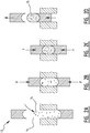
- FIG. 2A shows a press 13 in an opened state, where phase change material 14 is introduced into the press 13.
- a desired amount of graphite may be added to the phase change material 14, and/or even a binding material could be added, where it should be noted that graphite acts as a binder and also serves to enhance the heat transfer and storage capabilities of the phase change material.
- a sufficient amount of phase change material 14 (and optionally also graphite and/or binding material) has been inserted into the press 13, as shown in figure 2B and figure 2C , a force F is then exerted on the phase change material 14 inside the press 13. The volume of the phase change material 14 is thereby reduced and a compressed core of phase change material for production of the capsule is obtained.
- phase change material 14 By compression of the phase change material 14, a predefined shape of the core can be obtained, and moreover air is expelled from between the particles of the phase change material 14, resulting in a compact core with little remaining air therein, which air could inhibit a proper heat capacity or heat transfer capability.
- an improved core for production of capsules to be employed in the interior of the buffer tank 1 is provided.
- phase change material is compressed, even if a binder is used with which it can be ensured that no heat insulating air is left in the phase change material.
- a binder may comprise at least one of a plurality of materials, and merely as an example here is mentioned: graphite, hydrophilic polymers and Superabsorbent Polymers (SAP), such as polyacrylamid, polyacrylic acid, polyvinylalcohol and cellulose based polymers.
- SAP Superabsorbent Polymers
- the press 13 After compression of the phase change material 14 inside the press 13, as shown in figure 2D , the press 13 is opened to supply a pill shaped core 15 of compressed phase change material 14 for further production steps, to be described herein below (not according to the invention).
- FIG 3 charging the pill shaped cores 15 into mould cavity parts 19 of a second mould halve 16 is shown.
- a first mould halve 17 is pressed onto the second mould halve 16.
- the first mould halve 17 comprises slightly bigger mould cavity parts 21 then the mould cavity parts 19 of the second mould halve 16.
- channels 20 are arranged in the first mould halve 17 between the cavity parts 21 thereof.
- the first mould half 17 comprises an input 18 for thermoplastic material 22, to be inserted under pressure. When thermoplastic material 22 is inserted through the input 18, it flows through the channels 20 from one mould cavity part 21 to another in the direction away from the input 18.
- the channels 20 are filled with thermoplastic material 22, which after the injection moulding steps remains as an extension from one pill shaped core 15 to the next, connecting the separate cores 15 and also the resulting capsules.
- This connection formed in the channels 20 of the first mould halve 17 is consequently formed into greatly together with the watertight skins on and around the cores 15 of phase change material 14.
- the pill shaped cores 15 Since the thermoplastic material 22 is heated in order to become fluid and allow it to be inserted through the input 18, the pill shaped cores 15 must be able to withstand some heat and moreover also the pressure generated by the input of thermoplastic material 22.
- the pressure, with which the pill shaped cores 15 are produced in the steps shown in figure 2A - figure 2D impart a degree of heat resistance and more in particular also pressure resistance, sufficient to maintain the integrity as a pill shaped core 15 thereof during the subsequent step of injection moulding, as shown in figures 3-8 .
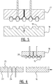
- the second mould halve 16 is removed, as shown in figure 5 , and the second mould halve 16 is replaced by a further second mould halve 23, as shown in figure 6 .
- the further second mould halve 23 also comprises an input 24 for thermoplastic material to form a completion of the watertight skin on and around the core 15.
- the further second mould halve 23 contains mould cavity parts 25 of the same dimensions as the mould cavity parts 21 of the first mould halve 17.
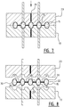
- thermoplastic material is introduced into an input of the further second mould halve 23 to complete skins on and around the cores 15 inside the mould cavities and to also complete the connections between neighbouring pill shaped cores 15.
- a string of capsules 30, interconnected by connections 31, can be taken out of the mould.
- Each capsule 30 comprises the pill shaped core 15 of phase change material 14 and a watertight skin 32, that is injection moulded around the cores 15, while simultaneously creating connections 31 between neighbouring capsules 30.
- the capsules 30 can be separated by severing the connection 31 there between, for instance by cutting or breaking. If the capsules 30 are capped in a string or array 33, as shown in figure 9 , preferably the time dimension of double arrow d in figure 9 is smaller than the size of at least one access into the interior of the buffer tank 1 in figure 1 .
- Access to the interior of the buffer tank 1 in figure 1 can be obtained through any one of the inputs 3, 4 or the outputs 5, 6 in figure 1 .
- These input connections and output connections have, normally, standard dimensions such as 15 mm or 22 mm, and the dimension of arrow d in figure 9 is consequently preferably slightly but sufficiently less than anyone of these standard access dimensions, to allow a string or array 33 of capsules 30 to be inserted into the interior of the buffer tank 1 in figure 1 through one of the accesses 3, 4, 5, 6.
- an isolated capsule 30 is shown.
- the skin 32 is partly broken away to expose the interior core 15 comprising phase changing material.
- the embodiment of figure 10 (not according to the invention) further also shows a separation line 34 between portions of the skin 32, where these portions are separately created in the moulding process steps shown in figure 4 and figure 7 , respectively.
- the dimension of arrow d is again depicted as a relevant dimension for allowing a capsule 30 of figure 11 to be introduced into an access into the interior of the buffer tank 1 in figure 1 .
- figure 11 also shows a length 1 of the capsule 30 and a radius r.
- the radius r is half the size of the dimension of the capsule 30, to create a rounded, smooth exterior of the capsule 30.
- the length of the capsule 30 can be chosen freely, as is shown for instance in figure 13 , where the capsule 35 is considerably longer than the capsule 30 of figure 10 .
- the length orientation of the capsules 30 could also be in line with the orientation of the connections 31, as shown in the embodiment of figure 12 .
- capsules 37 can be spherical, as shown in figure 14 .
- a mould part 38 is shown in perspective view, were the mould part 38 comprises four depressions 39, each defining a part of a mould cavity in a state, to form a complete mould cavity in combination with a further mould part (not shown in figure 15 ).
- pin-like support elements 40 are arranged in the depressions 39.
- Three support elements 40 are arranged in each of the depressions 39, to provide a stable accommodation for a spherical form-retaining core 41 of phase changing material.
- the pin like support elements 40 in the embodiment of figure 16 maintain a distance between the cavity 39 wall and the outer circumference of the spherical core 41.
- pin like support elements 14 can be employed to stably support an elongate core 42.
- a total of three support elements could in principle suffice to also accommodate an elongate core 42.
- More than four pins 40 can also be employed to support or accommodate any type or shape of core 41, 42. Consequently, injection moulding using thermoplastic material will entirely envelope the core 41. If no further measures are taken (see below) for this injection moulding process, repairs to close holes in a skin around the core 41, which may be caused by the pin-like support elements 40, will need to be performed for closing such holes.
- a mould part 45 comprises a plunger like base 43, which is pressed upwards in the mould part 45 in the direction of arrow E using a spring 44.
- the plunger like base 43 comprises a depression 46, defining at least a part of the mould cavity when combined with a supplemental mould part.
- a number of pin like support elements 47 are arranged, to support the core (not shown in figure 18 ) for or of a capsule during an injection moulding process.
- thermoplastic material will have surrounded the core, at which time the core will still be resting on the pin like support elements 47.
- the plunger like base 43 will be pushed back into the mould part 45 in the direction of arrow A, contrary to those spring for its of the spring 44.
- the plunger like base 43 comprises an annular ring 48, fitted in our recess 49 in the mould part 45. Enough fully extended position of the plunger like base 43, the clearance of distance B is available for movement of the plunger like base 43 in the direction of either arrow P or A.
- the clearance of double arrow B is available for movement of the plunger like base 43. Consequently, the clearance of double arrow B defines, restricts or limits the movement of the plunger like base 43 and core in combination with the die mention of the pin like support elements 47 defines a resulting thickness of the skin, to be arranged over and around the core of the capsule with the moulding process.
- This embodiment is designated as "passive" in the sense that movement of the plunger like base 43 is initiated by pressure in the mould cavity.
- FIG 19 an alternative embodiment is shown, where a first mould part and the second mould part are combined to define a mould cavity 51, where a core of phase change material can be accommodated on pin like support elements 50.
- a core of phase change material can be accommodated on pin like support elements 50.
- Each of the pin like elements can be actively withdrawn from the cavity 51 using a transmission 52 and a drive in the form of for instance a motor 53.
- a transmission 52 and a drive in the form of for instance a motor 53 With the pin like support elements 50 in an extended position thereof, a core for a capsule can be accommodated thereon.
- the two mould parts can be put together to define the cavity with the core therein, and supply of thermoplastic material through an input (not shown) can be initiated.
- the pin like support elements 50 may be actively withdrawn in the direction of arrow D, out of contact with the core. Thermoplastic material will immediately close any space remaining after the pin like support elements 50 have been actively withdrawn, thus avoiding any need for subsequent closing of such holes or any other imperfections or discontinuities.
- a grid 11 is provided in the embodiment of figure 1 to maintain the capsules 30 inside the buffer tank, but a collection of capsules can also be arranged inside a net or the like to present the capsules from being flushed out of the buffer tank.
- the thickness of the skin of the capsules is preferably small to allow as much phase change material as possible to be included in the capsules, but the integrity of the watertight skins must also be ensured.
- the skin has a thickness of between 10 and 600 ⁇ m, preferably between 20 and 580 ⁇ m, more preferably between 50 and 550 ⁇ m, and most preferably between 100 and 500 ⁇ m. Adding binder is optional.
- the skin comprises a skin material from PP Polypropylene.
- thermoplastic material or other skin material surrounding the core of the capsules to be produced in accordance with the present invention may have anyone of a selected or selectable number of colours.
- the chosen colour may coincide with and be coding for the phase change material in the core and/or a corresponding temperature range in use, after the capsules with the predetermined colours have been introduced into a vessel or tank, and thus in correspondence with the temperature is prevailing in use in said tank or vessel.
- an appropriate type of capsule can be selected on the basis of the colour selected for the skin thereof and in correspondence with the temperature range in use thereof in the tank or vessel.
Landscapes
- Chemical & Material Sciences (AREA)
- Engineering & Computer Science (AREA)
- Physics & Mathematics (AREA)
- Thermal Sciences (AREA)
- Organic Chemistry (AREA)
- Mechanical Engineering (AREA)
- General Engineering & Computer Science (AREA)
- Dispersion Chemistry (AREA)
- Chemical Kinetics & Catalysis (AREA)
- Combustion & Propulsion (AREA)
- Materials Engineering (AREA)
- Manufacturing & Machinery (AREA)
- Injection Moulding Of Plastics Or The Like (AREA)
Description
- The present invention relates to a capsule, having a core comprising phase changing material (PCM), as well as an assembly of a plurality of such capsules, for use in a buffer, and a production method for manufacturing such capsules or assemblies.
- The invention is based on the insight that the buffers in heating systems or heat exchange systems, like central heating systems, are usually filled with heat exchange fluids, like water. However, water and other usual heat exchange fluids have a limited heat capacity. According to the inventors of the present invention, it has been reported that phase change materials could be employed to enhance the heat capacity of a buffer, but to date no viable embodiment has been encountered.
- For example,
DE-10 2010 025297 relates to use of activated silicon having a solvent and other fluids included therein for the skin, which frees solvents and/or the other fluids into the PCM of the core after having been applied thereon. Further,DE-100 58 101 discloses a capsule having a core of PCM to which graphite may be added. Material for the core is supplied through an extruder or injector, which necessarily requires use of a solvent, such as paraffin. The presence of such a solvent fluid inside the core will inhibit a desired behaviour of the PCM in the core for storage of heat therein, as paraffin influences and even affects phase transitions of the PCM. Likewise,US4513053 andEP2119498 relate to use of polypropylene or the like as a coating or skin, wherein a solvent is necessary to be added to a base material for the coating or skin. Such solvent will be freed into the PCM after application of the coating or skin onto the core, where freed solvents or other fluids will affect the heat storing capacity or phase changing ability of the core material. - Consequently, to meet the needs of buffer builders and users, according to the present invention a capsule according to claim 1 and an assembly of capsules are provided. Since the loose core material is to be processed according to the present invention to be form retaining, for example in the shape of a ball, a cube, a tube, a cylinder and the like, the shape of the core can be maintained through a subsequent process step of applying the skin.
- As a consequence of these features of the present invention in relation to a capsule, it has become possible to enhance or increase heat capacity of a buffer by arranging the capsules therein, preferably though not exclusively in combination with the heat exchange fluid, which is still necessary to transfer heat from the buffer to other components of the heat exchanger system. The watertight skin prevents the phase change material from coming into contact with the heat exchange fluid, which would diminish the potential increase in heat capacity of a buffer. As a consequence of the feature that the phase change material of the core is, in dry conditions and without the skin, at least temporarily form-retaining, arranging the skin on the core is greatly facilitated to an extent where handling of the core in isolation prior to arranging the skin is possible. Injection moulding is employed for arranging the skin on or around the core in one-part whereas any and all prior art configurations rely on a two or more than two part combination of the skin and the steps for arranging the skin onto the core, to form or define a skin of a capsule. By creating a one piece skin, watertight properties to protect the core material from fluids and the like, will be enhanced relative to the available prior art, whilst prior art interface regions between separately applied skin parts are prone to allow leakages and the like.
- Form-retention can be achieved in one or more than one of many different manners, such as adding binder to, or compression of the phase change material of the core, and the like.
- Within the scope of protection for the present invention as defined in the appended independent claims, many preferred but not limiting embodiments are possible, some of which have been defined in appended dependent claims.
- For instance, in a preferred embodiment the core comprises salt hydrate. This is a very suitable phase change material, to be incorporated in a capsule according to the present invention, since heat capacity thereof surpasses that of water very considerably, but further also has a far superior heat capacity in terms of - for instance - enthalpy of fusion, than paraffin, sugar alcohol, regular salts, etc.
- According to the present invention, the core comprises graphite. Addition of graphite to the phase change material will enhance cohesion of the phase change material and heat storage and heat transfer through the phase change material. Additionally, a binder can be employed, preferably a binder exhibiting excellent heat transfer properties, and graphite or an alternative heat transfer enhancing additive may serve as a binder for the phase change material. With a binder, cohesion of the phase change material can be improved, and consequently also immediately the heat transfer properties of the phase change material in conjunction with the binder as well as the resulting heat capacity of the resulting capsule. For the binder, use can be made of one of a plurality of materials, and merely as an example here is mentioned hydrophilic polymers and Superabsorbent Polymers (SAP), such as polyacrylamid, polyacrylic acid, polyvinylalcohol and cellulose based polymers. For a general description of SAP, reference is made to http://en.wikipedia.org/wiki/Superabsorbent_polymer.
- According to the present invention, the core comprises compressed phase change material. By compressing the phase change material, the core can be given a shape and form best suitable for a subsequent step of applying the watertight skin on and around the core. Naturally a binder would or at least could contribute to the stability of a core in terms of its shape, prior to the watertight skin being applied to harness or at least encapsulate the phase change material in a desired shape and form and having desired dimensions.
- In an additional or alternative preferred embodiment of a capsule according to the present invention, the skin has a thickness of between 10 and 600 µm, preferably between 20 and 580 µm, more preferably between 50 and 550 µm, and most preferably between 100 and 500 µm. Such relatively thin watertight skins contribute to the desired feature of encapsulating as much phase change material as possible, while still being able to ensure outer dimensions of the resulting capsule, which under circumstances can be expected to have a maximum. Such relatively small thicknesses surprisingly suffice to ensure long term watertight properties of the capsules, in particular in non-restrictive embodiments having a one part or one piece skin arranged onto and/or around the core.
- For instance, in yet another alternative or additional preferred embodiment of the capsule according to the invention, a size thereof in at least one dimension, in particular a diameter, is smaller than a buffer or vessel connection, preferably smaller than 22 mm. In such a preferred embodiment, it is possible to transport a buffer or tank or vessel separate from the capsules, and the capsules can be introduced into the storage space defined by the buffer, tank or vessel at its destination. As a consequence, the weight of the buffer, tank or vessel to be transported can be reduced. In particular it is noted, that such a buffer, tank or vessel will normally be connected to the heat exchange system through a connection or a connector, usually having standard dimensions, such as 15 or 22 mm. As a consequence, the capsules in this preferred embodiment of the present invention can be introduced into the interior of the buffer, tank or vessel through the connection or connector, which will then subsequently served to connect the buffer, tank or vessel to the heat exchange system to become a part thereof, after filling with heat exchange fluid. The size of the capsules should be chosen such, that with certainty the capsules can be introduced into the interior of the buffer, tank or vessel, without the watertight skin being affected by puncture or rupture or other damage in contact with the rim of a connection or connector.
- According to the present invention, the skin comprises a skin material of PP Polypropylene. Polypropylene is considered to be an excellent choice for moulding, naturally with appropriate adaptations in relation to such manners of applying the watertight skin onto the core. According to the present invention, the skin is applied around the core through injection moulding of the skin around the core after arranging the core in a mould cavity.
- In yet another alternative or additional embodiment the capsule according to the present invention further comprises an extension protruding from the capsule. Such an extension may form a part of the core of phase change material or of the skin on and around the core, and is considered to be very useful for manoeuvring, handling and/or transporting of the resulting capsules and/or even of the intermediate products during production of the capsules.
- As previously indicated, the present invention also relates to an assembly of at least two capsules according to the present invention, wherein the capsules are connected to form an elongate string or array of capsules. Such a string or array of capsules can be introduced into an interior of a buffer, tank or vessel, one capsule at a time but with the assembly intact after inserting all of the capsules in the string or array, and the assembly may even be suspended or tensioned in this interior of the buffer, tank or vessel for at least temporarily storage of heat in the capsules. Strings of capsules may be more easily introduced into the buffer, tank or vessel, for example through an access, that can be easily made available for introduction of such string of capsules, for example a regular input connection to attach a conduit or the like of for instance a heating system and connect such a conduit or the like to the interior of the buffer, tank or vessel, provided the capsules fit through such a connection, without having to disassemble the buffer, tank or vessel, for which reason elsewhere not limiting dimensions of the capsules are mentioned in the present disclosure. Moreover, when the string is attached inside the buffer, tank or vessel, preferably near the connection, the string can also be easily retracted to be replaced or repaired or otherwise maintained. Alternatively, it is possible to break the connections between the capsules in a string or array to separately introduce the capsules into the interior of the buffer, tank or vessel, for instance by cutting or breaking such connections.
- It is noted in this respect, that in an embodiment of a capsule exhibiting an extension and an assembly of capsules, the extension can form the connection between the capsules. Consequently, this embodiment of an assembly is elegant and simple. For instance, when producing the assembly, using up moulding process for applying the watertight skin onto and around the core, the extension forming a connection between the capsules can be moulded at the same time as applying the watertight skin onto and around the
- As indicated herein above, the present invention can be used for a buffer, comprising: a tank or vessel, defining an internal storage for at least a heat exchange fluid and comprising a buffer connection for connection to an external heat exchange system; and at least one capsule according to the above described aspect of the present invention or an assembly according to yet another above described aspect of the present invention. The buffer may contain discrete capsules or strings or arrays of capsules in assemblies, possibly suspended or tensioned within the interior space of the tank, vessel or buffer to allow storage of heat in the capsules, which are in use in the tank, vessel or buffer in contact with the heat exchange liquid or even submerged therein.
- According to yet another aspect of the present invention, and as indicated above, the present invention also relates to a method of forming a capsule according to an above described aspect of the present invention, comprising: forming a core of phase changing material; and arranging an encapsulating watertight skin arranged around the core, wherein forming the core comprises processing the phase change material to be at least temporarily form-retaining in dry conditions and without the skin.
- The step of forming the core comprises adding graphite to the phase change material.
- The step of forming the core comprises compressing the phase change material. Thereby, air can be expelled from the core and a predefined shape of the core can be achieved. The presence of air inside the core could decrease the resulting heat capacity and transfer of a capsule, and a well defined intermediate shape of the core, prior to applying the watertight skin material on and around the core, has an evident beneficial influence on the subsequent step of applying the watertight skin material on and around the core. For instance, when a mould process is employed to arrange the watertight skin material on and around the core, which has accurate predefined dimensions, the thickness of the skin can be kept small so that a maximum amount of phase change material can be encapsulated in the capsule and the skin will then, as a consequence of the small thickness thereof, pose a minimal barrier for transfer of heat their through to the interior or core of the capsule or there from.
- In yet another additional or alternative embodiment of the method according to the present invention, forming the core and arranging the skin comprises dimensioning the capsule to a size thereof in at least one dimension, in particular a diameter, which is smaller than a buffer or vessel connection, preferably smaller than 22 mm or 15 mm.
- The step of arranging the skin comprises moulding of the skin around the core in a mould cavity after arranging the core in the mould cavity.
- In yet another additional or alternative preferred embodiment of a method according to the present invention, the method further comprises arranging an extension protruding from the capsule during the step of forming the core and/or the step of arranging the skin on and around the core.
- In yet another additional or alternative preferred embodiment of a method according to the present invention, using mould process, the method comprises arranging a core of phase change material in the mould cavity part in a first mould part; closing the mould using at least one second mould part; applying a thermoplastic skin material under pressure in a first direction; and applying thermoplastic skin material under pressure in a second direction essentially opposite the first direction relative to the core in the mould cavity. As a result of this preferred embodiment of the method, all sides around the circumference of the core will be provided with a suitable thickness of skin material, even when the core comprising the phase change material could rest against an interior surface of the mould cavity and consequently hinder application of skin material at such a resting position. If thermoplastic skin material under pressure is applied simultaneously in both the first direction and the second direction, the pressure could suffice to centre the core of the capsule within the mould cavity and allow application of thermoplastic skin material evenly and having a uniform thickness around the circumference thereof.
- However, as an alternative to simultaneous application of the thermoplastic skin material on and around the core and to even better ensure an even and uniform thickness of the skin material on and around the core, applying the thermoplastic skin material in the first and second directions may be performed in subsequent moulding steps.
- In such an embodiment having subsequent moulding steps at least one of the first and second mould halves is replaced for a latter of the subsequent moulding steps. A mould halve to be substituted between subsequent moulding steps can define a mould cavity, which is closely corresponding to the outer size and shape of the core during the first moulding step, and the replacing mould halve may have larger dimensions to allow for the thickness of the thermoplastic skin material and thus define an even and uniform skin thickness around the circumference of the capsule.
- In an embodiment of the present invention, the method for manufacturing capsules having an extension in a process based on moulding, the method may comprise moulding the extension. Moulding the extension can be performed simultaneously with applying in a mould process of the watertight skin of the capsule. The extension can form a connection to a neighbouring capsule in a string or array of capsules, forming an assembly in another aspect of the present invention.
- In an embodiment of the method according to the present invention, based on a mould process and with at least one extension on at least one of the capsules, the method may comprise manoeuvring the capsule by engaging the extension as a grip. This can be beneficial during production, for instance for handling the capsule, for instance for taking the capsule or string of capsules from a mould or mould halve after or during the production process.
- Yet another additional or alternative preferred embodiment of a method according to the present invention, could be comprising arranging a form-retaining core of phase change material on a support, which optionally comprises a plurality of support elements, in a mould cavity part in a first mould part; closing the mould using at least one second mould part, optionally also comprising a support; and applying a thermoplastic skin material under pressure to the mould cavity. By arranging the core on the support, the core may be kept in alignment with walls of the moulding cavity, for example for elongate embodiments, but in any case with certainty away from walls of the mould cavity to ensure a desired thickness of the skin on the core. Consequently an improvement may be achieved with respect to all round arranging of the skin on the core in the moulding process. If a plurality of support elements are used, for example three support elements for a sphere-like core, or more support elements for more general or rectangular of square or elongate shapes of the core, the locations of contact between the core and the support elements can be relatively small. Nonetheless, any discontinuities or even holes in the skin need to be augmented or even repaired for proper use of the resulting capsules. In this respect such an embodiment of a method according to the invention may further comprise active or passive retraction of the support a time after initiating application of thermoplastic material into the mould cavity, optionally in conjunction with a base carrying the support, which may be plunger shaped, to yield under moulding pressure a space in the mould cavity for applying a skin of a desired thickness around the core. The support or support elements may be retractable after the moulding process under pressure has started. Retraction may be the result (passive) of the moulding pressure, or be an active step of engaging and retracting the support or support elements, for example using motorised engagement of the support or support element. It is especially beneficial, if the support or support elements is/are on a plunger type of base, forced by for example spring pressure towards the cavity and defining a wall thereof. As a consequence of pressure build up in the cavity, the base may be pushed against the spring force back from the core, to still define a mould cavity wall, and allow the core to be completely surrounded with thermoplastic material for the skin, without any discontinuities or even holes.
- The present invention also relates to a mould having a support for the core, which may be passively or actively retractable.
- Following from the above more general discussion of the present invention, herein below a detailed description of specific aspects of the present invention is set out, referring to the appended drawings of non-limiting embodiments of the present invention, wherein the same or similar aspects, components and features can be identified using the same reference numbers in different figures, and wherein:
-
figure 1 shows a buffer in a partly cut open view, having capsules according to the present invention inserted therein, both in the form of discrete capsules and strings or arrays of capsules; -
figure 2A-2D shows steps of compressing phase change material to define a compressed core for capsules according to the present invention; -
figure 3 shows preparations for the moulding process to arrange a skin on and around the compressed core of phase change material; -
figure 4 shows the first step of inserting thermoplastic skin material into a mould cavity to arrange the thermoplastic skin material on and around at least a part of the predefined core of the capsule; -
figure 5 shows the subsequent step after the step offigure 4 , where a mould halve is replaced by another mould halve as depicted infigure 6 ; -
figure 7 shows the second step of inserting thermoplastic skin material into the mould cavity; and -
figure 8 shows extracting a string of capsules according to the present invention from the mould; -
figure 9 shows a perspective view of the string or array of capsules forming an assembly in the sense of the present invention; -
figure 10 shows a partly cutaway view of a single capsule according to the present invention, having a core and a skin, where the capsule infigure 10 is produced in isolation or isolated from a string or array of capsules like the one, shown infigure 9 ; -
figure 11 shows a designed shape of a single capsule according to the present invention in side view; -
figures 12 and 14 show alternative embodiments relative to the one offigure 9 ; -
figure 13 shows an alternative embodiment relative to the one offigure 10 or 11 ; -
figure 15 shows a perspective view of a mould part, defining four mould cavities partially; -
figure 16 shows the sectional view in the direction of arrows XVI - XVI infigure 1 ; -
figure 17 shows an alternative mould cavity shape and resulting capsule, relative to the embodiment offigures 15 and 16 ; -
figure 18 shows an additional embodiment having a plunger like base with support elements thereon for accommodating a core of form-retaining phase changing material in a stable manner during injection moulding, based on passive retraction of support elements; and -
figure 19 shows an alternative embodiment relative tofigure 18 , based on active retraction of support elements and without a plunger like base. - In
figure 1 , a buffer tank 1 according to an embodiment of the present invention is shown. The buffer tank 1 comprises enclosingwalls 2, defining aninterior space 7 for accommodating a heat transfer fluid 8 anddiscrete capsules 9 and strings or arrays ofcapsules 10. Theinterior space 7 of the buffer tank 1 may accommodatediscrete capsules 9 and/or strings or arrays ofcapsules 10. - An input connection 3 extends through
wall 2 of buffer tank 1, to allow input of heated heat exchange fluid 8, for instance water. The input connection 3 is arranged at or near the top of the buffer tank 1. At or near the bottom of the buffer tank 1 anoutput connection 6 is arranged. A mesh or grid 11 is provided to preventdiscrete capsules 9 or strings ofcapsules 10 to be washed out of the interior space of the buffer tank 1. - A coiled tube or
hose 12 extends between and input 4 and anoutput 5, through which for instance tap water can flow to heat the tap water and provide, at theoutput 5, heated tap water for use thereof by consumers, or as a contribution to a heating system, such as a central heating system for warming rooms of a building. -
Figure 2A shows apress 13 in an opened state, wherephase change material 14 is introduced into thepress 13. A desired amount of graphite may be added to thephase change material 14, and/or even a binding material could be added, where it should be noted that graphite acts as a binder and also serves to enhance the heat transfer and storage capabilities of the phase change material. When a sufficient amount of phase change material 14 (and optionally also graphite and/or binding material) has been inserted into thepress 13, as shown infigure 2B and figure 2C , a force F is then exerted on thephase change material 14 inside thepress 13. The volume of thephase change material 14 is thereby reduced and a compressed core of phase change material for production of the capsule is obtained. By compression of thephase change material 14, a predefined shape of the core can be obtained, and moreover air is expelled from between the particles of thephase change material 14, resulting in a compact core with little remaining air therein, which air could inhibit a proper heat capacity or heat transfer capability. By expelling the air and compressing thephase change material 14, an improved core for production of capsules to be employed in the interior of the buffer tank 1 is provided. - It is noted here that according to the invention the phase change material is compressed, even if a binder is used with which it can be ensured that no heat insulating air is left in the phase change material.
- A binder may comprise at least one of a plurality of materials, and merely as an example here is mentioned: graphite, hydrophilic polymers and Superabsorbent Polymers (SAP), such as polyacrylamid, polyacrylic acid, polyvinylalcohol and cellulose based polymers. For a general description of SAP, reference is made to http://en.wikipedia.org/wiki/Superabsorbent_polymer.
- After compression of the
phase change material 14 inside thepress 13, as shown infigure 2D , thepress 13 is opened to supply a pill shapedcore 15 of compressedphase change material 14 for further production steps, to be described herein below (not according to the invention). - In
figure 3 , charging the pill shapedcores 15 intomould cavity parts 19 of a second mould halve 16 is shown. After allmould cavities 19 of the second mould halve 16 are filled with each one pill shapedcore 15, a first mould halve 17 is pressed onto the second mould halve 16. The first mould halve 17 comprises slightly biggermould cavity parts 21 then themould cavity parts 19 of the second mould halve 16. Further,channels 20 are arranged in the first mould halve 17 between thecavity parts 21 thereof. Further, thefirst mould half 17 comprises aninput 18 forthermoplastic material 22, to be inserted under pressure. Whenthermoplastic material 22 is inserted through theinput 18, it flows through thechannels 20 from onemould cavity part 21 to another in the direction away from theinput 18. Consequently, thechannels 20 are filled withthermoplastic material 22, which after the injection moulding steps remains as an extension from one pill shapedcore 15 to the next, connecting theseparate cores 15 and also the resulting capsules. This connection formed in thechannels 20 of the first mould halve 17 is consequently formed into greatly together with the watertight skins on and around thecores 15 ofphase change material 14. - Since the
thermoplastic material 22 is heated in order to become fluid and allow it to be inserted through theinput 18, the pill shapedcores 15 must be able to withstand some heat and moreover also the pressure generated by the input ofthermoplastic material 22. The pressure, with which the pill shapedcores 15 are produced in the steps shown infigure 2A - figure 2D , impart a degree of heat resistance and more in particular also pressure resistance, sufficient to maintain the integrity as a pill shapedcore 15 thereof during the subsequent step of injection moulding, as shown infigures 3-8 . - Subsequent to the step of injection moulding as shown in
figure 4 , the second mould halve 16 is removed, as shown infigure 5 , and the second mould halve 16 is replaced by a further second mould halve 23, as shown infigure 6 . The further second mould halve 23 also comprises aninput 24 for thermoplastic material to form a completion of the watertight skin on and around thecore 15. To achieve this, the further second mould halve 23 containsmould cavity parts 25 of the same dimensions as themould cavity parts 21 of the first mould halve 17. - From the situation of
figure 6 with the further second mould halve 23 pressed against the first mould halve 17, to arrive at the situation depicted infigure 7 , the assembly of the first mould halve 17 and the further second mould halve 23 is turned upside down. Then, thermoplastic material is introduced into an input of the further second mould halve 23 to complete skins on and around thecores 15 inside the mould cavities and to also complete the connections between neighbouring pill shapedcores 15. - When the mould halves 17, 23 are taken apart, as shown in
figure 8 , a string ofcapsules 30, interconnected byconnections 31, can be taken out of the mould. Eachcapsule 30 comprises the pill shapedcore 15 ofphase change material 14 and awatertight skin 32, that is injection moulded around thecores 15, while simultaneously creatingconnections 31 between neighbouringcapsules 30. After release of the string orarray 33 ofcapsules 30, as shown in perspective view infigure 9 , thecapsules 30 can be separated by severing theconnection 31 there between, for instance by cutting or breaking. If thecapsules 30 are capped in a string orarray 33, as shown infigure 9 , preferably the time dimension of double arrow d infigure 9 is smaller than the size of at least one access into the interior of the buffer tank 1 infigure 1 . Access to the interior of the buffer tank 1 infigure 1 can be obtained through any one of the inputs 3, 4 or theoutputs figure 1 . These input connections and output connections have, normally, standard dimensions such as 15 mm or 22 mm, and the dimension of arrow d infigure 9 is consequently preferably slightly but sufficiently less than anyone of these standard access dimensions, to allow a string orarray 33 ofcapsules 30 to be inserted into the interior of the buffer tank 1 infigure 1 through one of theaccesses - In the embodiment of
figure 10 and 11 , anisolated capsule 30 is shown. Infigure 10 theskin 32 is partly broken away to expose theinterior core 15 comprising phase changing material. The embodiment offigure 10 (not according to the invention) further also shows aseparation line 34 between portions of theskin 32, where these portions are separately created in the moulding process steps shown infigure 4 andfigure 7 , respectively. - In
figure 11 the dimension of arrow d is again depicted as a relevant dimension for allowing acapsule 30 offigure 11 to be introduced into an access into the interior of the buffer tank 1 infigure 1 . - Further,
figure 11 also shows a length 1 of thecapsule 30 and a radius r. The radius r is half the size of the dimension of thecapsule 30, to create a rounded, smooth exterior of thecapsule 30. The length of thecapsule 30 can be chosen freely, as is shown for instance infigure 13 , where thecapsule 35 is considerably longer than thecapsule 30 offigure 10 . As an alternative to the assembly embodiment of the string orarray 33 ofcapsules 30, having a length dimension at a straight angle relative to the orientation of theconnections 31, the length orientation of thecapsules 30 could also be in line with the orientation of theconnections 31, as shown in the embodiment offigure 12 . Yet further as an alternative,capsules 37 can be spherical, as shown infigure 14 . - In
figure 15 amould part 38 is shown in perspective view, were themould part 38 comprises fourdepressions 39, each defining a part of a mould cavity in a state, to form a complete mould cavity in combination with a further mould part (not shown infigure 15 ). As shown infigure 15 and infigure 16 , pin-like support elements 40 are arranged in thedepressions 39. Threesupport elements 40 are arranged in each of thedepressions 39, to provide a stable accommodation for a spherical form-retainingcore 41 of phase changing material. The pin likesupport elements 40 in the embodiment offigure 16 maintain a distance between thecavity 39 wall and the outer circumference of thespherical core 41. Likewise, in a configuration according tofigure 17 , four pin likesupport elements 14 can be employed to stably support anelongate core 42. A total of three support elements could in principle suffice to also accommodate anelongate core 42. More than fourpins 40 can also be employed to support or accommodate any type or shape ofcore core 41. If no further measures are taken (see below) for this injection moulding process, repairs to close holes in a skin around thecore 41, which may be caused by the pin-like support elements 40, will need to be performed for closing such holes. Especially if an intermediate product having a core 41 and a skin arranged their around using the moulding process as depicted in figure is 15 and 16 is taken out of a mould cavity with the skin material still in a plastic state to at least some degree, such holes can easily and simply be repaired by putting some pressure on the skin material surrounding such holes. However, this would entail a further processing step, which can be considered additional and consequently even undesirable. - In
figure 18 , amould part 45 comprises a plunger likebase 43, which is pressed upwards in themould part 45 in the direction of arrow E using aspring 44. At the top infigure 18 , the plunger likebase 43 comprises adepression 46, defining at least a part of the mould cavity when combined with a supplemental mould part. In thedepression 46, a number of pin likesupport elements 47 are arranged, to support the core (not shown infigure 18 ) for or of a capsule during an injection moulding process. When the shownmould part 45 offigure 18 is combined with a (not shown) supplemental mould part to define a mould cavity, at least partially by thedepression 46, thermoplastic material may be introduced into the mould cavity, where initially the core will be accommodated on the pin like support elements. After a short time, thermoplastic material will have surrounded the core, at which time the core will still be resting on the pin likesupport elements 47. As a consequence of subsequent pressure increase in the direction of generally arrow P, the plunger likebase 43 will be pushed back into themould part 45 in the direction of arrow A, contrary to those spring for its of thespring 44. - The plunger like
base 43 comprises anannular ring 48, fitted in ourrecess 49 in themould part 45. Enough fully extended position of the plunger likebase 43, the clearance of distance B is available for movement of the plunger likebase 43 in the direction of either arrow P or A. When, during the moulding process, the pressure in the mould cavity has sufficiently reason for the plunger likebase 43 to recede into the body of themould part 45, the clearance of double arrow B is available for movement of the plunger likebase 43. Consequently, the clearance of double arrow B defines, restricts or limits the movement of the plunger likebase 43 and core in combination with the die mention of the pin likesupport elements 47 defines a resulting thickness of the skin, to be arranged over and around the core of the capsule with the moulding process. - This embodiment is designated as "passive" in the sense that movement of the plunger like
base 43 is initiated by pressure in the mould cavity. - In
figure 19 , an alternative embodiment is shown, where a first mould part and the second mould part are combined to define amould cavity 51, where a core of phase change material can be accommodated on pin likesupport elements 50. Each of the pin like elements can be actively withdrawn from thecavity 51 using atransmission 52 and a drive in the form of for instance amotor 53. With the pin likesupport elements 50 in an extended position thereof, a core for a capsule can be accommodated thereon. Subsequently, the two mould parts can be put together to define the cavity with the core therein, and supply of thermoplastic material through an input (not shown) can be initiated. After it has been determined, that a sufficient amount of thermoplastic material is surrounding the core of the capsule, the pin likesupport elements 50 may be actively withdrawn in the direction of arrow D, out of contact with the core. Thermoplastic material will immediately close any space remaining after the pin likesupport elements 50 have been actively withdrawn, thus avoiding any need for subsequent closing of such holes or any other imperfections or discontinuities. - After the foregoing disclosure in detail of the invention, many additional and/or alternative embodiments will have become abundantly apparent to the skilled person. All such additional and/or alternative embodiments are to be considered as embodiments of the present invention in as far as such additional and/or alternative embodiments comply with the required features of at least the appended independent claims, and neither the specifically described embodiments nor the inferred alternative and/or additional embodiments are to be considered a limitation on the scope of protection as defined in the appended independent claims. For instance, the capsules can be employed in another buffer tank than the one that is depicted in
figure 1 . Further, a grid 11 is provided in the embodiment offigure 1 to maintain thecapsules 30 inside the buffer tank, but a collection of capsules can also be arranged inside a net or the like to present the capsules from being flushed out of the buffer tank. The thickness of the skin of the capsules is preferably small to allow as much phase change material as possible to be included in the capsules, but the integrity of the watertight skins must also be ensured. For this, the skin has a thickness of between 10 and 600 µm, preferably between 20 and 580 µm, more preferably between 50 and 550 µm, and most preferably between 100 and 500 µm. Adding binder is optional. The skin comprises a skin material from PP Polypropylene. - In this respect it is further noted, that the thermoplastic material or other skin material surrounding the core of the capsules to be produced in accordance with the present invention, may have anyone of a selected or selectable number of colours. The chosen colour may coincide with and be coding for the phase change material in the core and/or a corresponding temperature range in use, after the capsules with the predetermined colours have been introduced into a vessel or tank, and thus in correspondence with the temperature is prevailing in use in said tank or vessel. As a consequence, prior to use of the capsules to be produced in accordance with the present invention, an appropriate type of capsule can be selected on the basis of the colour selected for the skin thereof and in correspondence with the temperature range in use thereof in the tank or vessel.
Claims (9)
- A capsule, which is adapted to be arranged in a buffer or vessel and for selective heat storage in and/or selective heat release from the capsule, the capsule comprising: the core, comprising a particulate phase change material, and an encapsulating watertight skin arranged around the core, CHARACTERISED IN THAT
the core comprises, in addition to the particulate phase change material, graphite to, in a dry state thereof and without the skin, provide enhanced cohesion to the phase change material and to provide enhanced heat storage and heat transfer through the phase change material, where the encapsulating watertight skin comprises injection moulded polypropylene, which is arranged in one piece around the core of compressed particulate phase change material with graphite added thereto. - The capsule of claim 1, wherein a size of the capsule in at least one dimension, in particular a diameter, is smaller than 22 mm.
- The capsule of any of the preceding claims, comprising further an extension protruding from the capsule.
- An assembly of at least two capsules according to any one of the preceding claims, wherein the capsules are connected to form an elongate string of capsules, wherein the extension of at least one of the capsules according to claim 3 form a connection between capsules in the string.
- A method of forming a capsule according to at least one of the preceding claims 1 - 3, or an assembly according to claim 4, comprising a step of adding graphite to the phase change material and a step of compressing the phase change material for the core to maintain a shape thereof, wherein the graphite is added to provide enhanced cohesion to the phase change material in a dry state in isolation of the core, before application of the encapsulating watertight skin onto the core for forming the capsule, wherein adding graphite comprises providing enhanced heat storage and heat transfer through the phase change material, arranging the core in a mould cavity and applying the encapsulating watertight skin in one piece by injection moulding of polypropylene into the mould cavity to arrange the thermoplastic material around the compressed particulate phase change material with the graphite added thereto.
- The method of claim 5, wherein the step of forming the core comprises: adding binder to the phase change material.
- The method of claim 5 or 6, comprising arranging a core of phase change material in the mould cavity part in a first mould part; closing the mould using at least one second mould part; applying a thermoplastic skin material under pressure in a first direction; and applying thermoplastic skin material under pressure in a second direction essentially opposite the first direction relative to the core in the mould cavity.
- The method of any one of preceding claims 5 - 7, using a mould process, comprising arranging the core of phase change material on a support, which optionally comprises a plurality of support elements, in a mould cavity part in a first mould part; closing the mould using at least one second mould part, optionally also comprising a support; and applying the encapsulating watertight skin of a thermoplastic skin material under pressure to the mould cavity.
- The method according to claim 8, further comprising active or passive retraction of the support a time after initiating application of thermoplastic material into the mould cavity, optionally in conjunction with a base carrying the support, which may be plunger shaped, to yield under moulding pressure a space in the mould cavity for applying the encapsulating watertight skin of a desired thickness around the core.
Priority Applications (1)
| Application Number | Priority Date | Filing Date | Title |
|---|---|---|---|
| EP13785868.4A EP2914376B1 (en) | 2012-11-05 | 2013-11-01 | Capsule comprising phase change material, assembly of capsules and method of forming the capsule |
Applications Claiming Priority (3)
| Application Number | Priority Date | Filing Date | Title |
|---|---|---|---|
| EP12191312.3A EP2727646A1 (en) | 2012-11-05 | 2012-11-05 | Capsule comprising phase change material, assembly, thermal buffer, and method |
| PCT/EP2013/072877 WO2014068091A1 (en) | 2012-11-05 | 2013-11-01 | Core of a capsule comprising phase change material, assembly of capsules, thermal buffer, and method |
| EP13785868.4A EP2914376B1 (en) | 2012-11-05 | 2013-11-01 | Capsule comprising phase change material, assembly of capsules and method of forming the capsule |
Publications (2)
| Publication Number | Publication Date |
|---|---|
| EP2914376A1 EP2914376A1 (en) | 2015-09-09 |
| EP2914376B1 true EP2914376B1 (en) | 2017-03-01 |
Family
ID=47357913
Family Applications (2)
| Application Number | Title | Priority Date | Filing Date |
|---|---|---|---|
| EP12191312.3A Withdrawn EP2727646A1 (en) | 2012-11-05 | 2012-11-05 | Capsule comprising phase change material, assembly, thermal buffer, and method |
| EP13785868.4A Active EP2914376B1 (en) | 2012-11-05 | 2013-11-01 | Capsule comprising phase change material, assembly of capsules and method of forming the capsule |
Family Applications Before (1)
| Application Number | Title | Priority Date | Filing Date |
|---|---|---|---|
| EP12191312.3A Withdrawn EP2727646A1 (en) | 2012-11-05 | 2012-11-05 | Capsule comprising phase change material, assembly, thermal buffer, and method |
Country Status (3)
| Country | Link |
|---|---|
| US (1) | US20150285565A1 (en) |
| EP (2) | EP2727646A1 (en) |
| WO (1) | WO2014068091A1 (en) |
Families Citing this family (9)
| Publication number | Priority date | Publication date | Assignee | Title |
|---|---|---|---|---|
| JP6386807B2 (en) * | 2014-06-23 | 2018-09-05 | ミサワホーム株式会社 | Thermal storage unit and air conditioning system |
| CN104804711B (en) * | 2015-03-06 | 2019-05-10 | 深圳大学 | Embedded thermal conductivity enhanced phase change energy storage microcapsule and preparation method thereof |
| US11248810B2 (en) | 2016-02-25 | 2022-02-15 | Fruition Llc | Portable apparatus and methods using phase change materials for creating a temperature stabilized environment |
| WO2017147287A1 (en) | 2016-02-25 | 2017-08-31 | Fruition Llc | Portable apparatus and methods using phase change materials for creating a temperature stabilized environment |
| FR3052547B1 (en) * | 2016-06-10 | 2019-12-20 | Hutchinson | CENTERING DEVICE IN A VOLUME |
| FR3085841B1 (en) * | 2018-09-14 | 2020-12-04 | Oreal | CAPSULE PREPARATION PROCESS AND ASSOCIATED SYSTEM |
| CN111452335A (en) * | 2020-04-08 | 2020-07-28 | 王丽枝 | Plastic bottle forming die |
| GB202101678D0 (en) | 2021-02-07 | 2021-03-24 | Octopus Energy Ltd | Methods and systems and apparatus to support reduced energy and water usage |
| WO2022168024A1 (en) * | 2021-02-07 | 2022-08-11 | Octopus Energy Group Limited | Energy storage arrangements and installations including such energy storage arrangements |
Family Cites Families (13)
| Publication number | Priority date | Publication date | Assignee | Title |
|---|---|---|---|---|
| US4355627A (en) * | 1978-06-06 | 1982-10-26 | Scarlata Robert W | Thermal storage system |
| EP0101181B1 (en) * | 1982-07-15 | 1986-02-12 | Ic Gas International Limited | Heat storage materials, and method of heat exchange therewith |
| US4513053A (en) * | 1983-06-13 | 1985-04-23 | Pennwalt Corporation | Encapsulated phase change thermal energy storage materials and process |
| JPS6245680A (en) * | 1985-08-23 | 1987-02-27 | Matsushita Electric Works Ltd | Heat storing capsule, process for preparing the same and heat storing building material |
| JPS63273787A (en) * | 1987-04-30 | 1988-11-10 | Kubota Ltd | Capsule for heat accumulating material |
| JPS63309580A (en) * | 1987-06-12 | 1988-12-16 | Nok Corp | Production of heat storage material capsule |
| US6099894A (en) * | 1998-07-27 | 2000-08-08 | Frisby Technologies, Inc. | Gel-coated microcapsules |
| DE10058101A1 (en) * | 2000-11-23 | 2002-06-06 | Rubitherm Gmbh | Latent heat storage body, method for producing a latent heat storage body, method for producing a film-like latent heat storage body and method for coating a carrier material |
| EP1598406B1 (en) * | 2004-05-18 | 2013-08-07 | SGL Carbon SE | Latent heat storage material |
| DE102007023315B3 (en) * | 2007-05-16 | 2008-10-16 | BAM Bundesanstalt für Materialforschung und -prüfung | Process for producing a latent heat storage material |
| ES2306624B1 (en) * | 2008-05-12 | 2009-10-14 | Acciona Infraestructura S.A. | PROCEDURE FOR THE MICROENCAPSULATE OF PHASE CHANGE MATERIALS BY DRYING BY SPRAYING. |
| DE102009013189A1 (en) * | 2009-03-17 | 2010-09-23 | Stiebel Eltron Gmbh & Co. Kg | Hot water storage device useful in catering or in transport box for drugs, comprises capsules to receive phase change material, where the capsules have lower half-shell and upper half-shell, which completely surround phase change material |
| DE102010025297A1 (en) * | 2010-06-28 | 2011-12-29 | Institut für Luft- und Kältetechnik gGmbH | Method for manufacturing latent heat storage body utilized in heat exchanger container, involves forming capsule by capsule parts according to outer contour of filling bodies while introducing capsule filling in solid phase |
-
2012
- 2012-11-05 EP EP12191312.3A patent/EP2727646A1/en not_active Withdrawn
-
2013
- 2013-11-01 EP EP13785868.4A patent/EP2914376B1/en active Active
- 2013-11-01 WO PCT/EP2013/072877 patent/WO2014068091A1/en not_active Ceased
- 2013-11-01 US US14/440,525 patent/US20150285565A1/en not_active Abandoned
Non-Patent Citations (1)
| Title |
|---|
| None * |
Also Published As
| Publication number | Publication date |
|---|---|
| EP2914376A1 (en) | 2015-09-09 |
| EP2727646A1 (en) | 2014-05-07 |
| WO2014068091A1 (en) | 2014-05-08 |
| US20150285565A1 (en) | 2015-10-08 |
Similar Documents
| Publication | Publication Date | Title |
|---|---|---|
| US20150285565A1 (en) | Core of a Capsule Comprising Phase Change Material, Assembly of Capsules, Thermal Buffer, and Method | |
| CN104074972B (en) | Method and apparatus for forming the matrix lining of pressure vessel | |
| EP2590792B1 (en) | Method for manufacturing an insulated pipe using a bag | |
| CN101432118A (en) | Capsule for preparing a beverage with a watertight seal and method for manufacturing the same | |
| EP1552351B1 (en) | Mechanical component having at least one fluid transport circuit and method for designing same in strata | |
| CN109880596B (en) | A kind of gradient phase change heat storage body and preparation method thereof | |
| CN101726205A (en) | Method for manufacturing flat plate type heat pipe | |
| CN102078962A (en) | Mold for forming multi-channel filter element and method for forming intermetallic compound multi-channel filter element | |
| CN110290909B (en) | Method for producing containers | |
| EP2933010B1 (en) | Thermoforming of fiber bundles | |
| CN103410692B (en) | A kind of expanded capsule and Power Drive Unit that power is provided | |
| CN203957322U (en) | metal embedded heater | |
| WO2020229698A1 (en) | Method of producing composite springs, and of a mold core for such method | |
| CN204375567U (en) | A kind of square polypropylene capactive | |
| US20170003084A1 (en) | Absorption body for a capsule containing a phase-change material | |
| CN106827432B (en) | Synchronous cooling type injection molding device | |
| DE102009013189A1 (en) | Hot water storage device useful in catering or in transport box for drugs, comprises capsules to receive phase change material, where the capsules have lower half-shell and upper half-shell, which completely surround phase change material | |
| CN102672173B (en) | Mold for forming multi-channel filter element and method for forming intermetallic compound multi-channel filter element | |
| KR102174239B1 (en) | Method for manufacturing core for gravity casting | |
| CN201589569U (en) | Pressure-resistant energy storage heat exchange container that can be filled with phase change materials | |
| US8071005B2 (en) | Method and plant for the production of a casing for a solid-propellant engine | |
| CN106989978B (en) | A kind of combination die of laser melting coating part polishing | |
| CN201405513Y (en) | Insert fixing device for compression moulding die | |
| KR101509189B1 (en) | Apparatus of manufacturing water capsule | |
| US20260034709A1 (en) | Syntactic-foam parts and associated methods of making the same |
Legal Events
| Date | Code | Title | Description |
|---|---|---|---|
| PUAI | Public reference made under article 153(3) epc to a published international application that has entered the european phase |
Free format text: ORIGINAL CODE: 0009012 |
|
| 17P | Request for examination filed |
Effective date: 20150501 |
|
| AK | Designated contracting states |
Kind code of ref document: A1 Designated state(s): AL AT BE BG CH CY CZ DE DK EE ES FI FR GB GR HR HU IE IS IT LI LT LU LV MC MK MT NL NO PL PT RO RS SE SI SK SM TR |
|
| AX | Request for extension of the european patent |
Extension state: BA ME |
|
| DAX | Request for extension of the european patent (deleted) | ||
| GRAP | Despatch of communication of intention to grant a patent |
Free format text: ORIGINAL CODE: EPIDOSNIGR1 |
|
| RIC1 | Information provided on ipc code assigned before grant |
Ipc: C09K 5/06 20060101ALI20160926BHEP Ipc: F28D 20/02 20060101ALI20160926BHEP Ipc: F28D 20/00 20060101ALI20160926BHEP Ipc: B01J 13/04 20060101AFI20160926BHEP |
|
| INTG | Intention to grant announced |
Effective date: 20161021 |
|
| GRAS | Grant fee paid |
Free format text: ORIGINAL CODE: EPIDOSNIGR3 |
|
| GRAA | (expected) grant |
Free format text: ORIGINAL CODE: 0009210 |
|
| AK | Designated contracting states |
Kind code of ref document: B1 Designated state(s): AL AT BE BG CH CY CZ DE DK EE ES FI FR GB GR HR HU IE IS IT LI LT LU LV MC MK MT NL NO PL PT RO RS SE SI SK SM TR |
|
| REG | Reference to a national code |
Ref country code: GB Ref legal event code: FG4D |
|
| REG | Reference to a national code |
Ref country code: CH Ref legal event code: EP Ref country code: AT Ref legal event code: REF Ref document number: 870628 Country of ref document: AT Kind code of ref document: T Effective date: 20170315 |
|
| REG | Reference to a national code |
Ref country code: IE Ref legal event code: FG4D |
|
| REG | Reference to a national code |
Ref country code: DE Ref legal event code: R096 Ref document number: 602013018057 Country of ref document: DE |
|
| REG | Reference to a national code |
Ref country code: NL Ref legal event code: FP |
|
| REG | Reference to a national code |
Ref country code: LT Ref legal event code: MG4D |
|
| REG | Reference to a national code |
Ref country code: AT Ref legal event code: MK05 Ref document number: 870628 Country of ref document: AT Kind code of ref document: T Effective date: 20170301 |
|
| PG25 | Lapsed in a contracting state [announced via postgrant information from national office to epo] |
Ref country code: FI Free format text: LAPSE BECAUSE OF FAILURE TO SUBMIT A TRANSLATION OF THE DESCRIPTION OR TO PAY THE FEE WITHIN THE PRESCRIBED TIME-LIMIT Effective date: 20170301 Ref country code: HR Free format text: LAPSE BECAUSE OF FAILURE TO SUBMIT A TRANSLATION OF THE DESCRIPTION OR TO PAY THE FEE WITHIN THE PRESCRIBED TIME-LIMIT Effective date: 20170301 Ref country code: LT Free format text: LAPSE BECAUSE OF FAILURE TO SUBMIT A TRANSLATION OF THE DESCRIPTION OR TO PAY THE FEE WITHIN THE PRESCRIBED TIME-LIMIT Effective date: 20170301 Ref country code: NO Free format text: LAPSE BECAUSE OF FAILURE TO SUBMIT A TRANSLATION OF THE DESCRIPTION OR TO PAY THE FEE WITHIN THE PRESCRIBED TIME-LIMIT Effective date: 20170601 Ref country code: GR Free format text: LAPSE BECAUSE OF FAILURE TO SUBMIT A TRANSLATION OF THE DESCRIPTION OR TO PAY THE FEE WITHIN THE PRESCRIBED TIME-LIMIT Effective date: 20170602 |
|
| PG25 | Lapsed in a contracting state [announced via postgrant information from national office to epo] |
Ref country code: AT Free format text: LAPSE BECAUSE OF FAILURE TO SUBMIT A TRANSLATION OF THE DESCRIPTION OR TO PAY THE FEE WITHIN THE PRESCRIBED TIME-LIMIT Effective date: 20170301 Ref country code: LV Free format text: LAPSE BECAUSE OF FAILURE TO SUBMIT A TRANSLATION OF THE DESCRIPTION OR TO PAY THE FEE WITHIN THE PRESCRIBED TIME-LIMIT Effective date: 20170301 Ref country code: SE Free format text: LAPSE BECAUSE OF FAILURE TO SUBMIT A TRANSLATION OF THE DESCRIPTION OR TO PAY THE FEE WITHIN THE PRESCRIBED TIME-LIMIT Effective date: 20170301 Ref country code: RS Free format text: LAPSE BECAUSE OF FAILURE TO SUBMIT A TRANSLATION OF THE DESCRIPTION OR TO PAY THE FEE WITHIN THE PRESCRIBED TIME-LIMIT Effective date: 20170301 Ref country code: BG Free format text: LAPSE BECAUSE OF FAILURE TO SUBMIT A TRANSLATION OF THE DESCRIPTION OR TO PAY THE FEE WITHIN THE PRESCRIBED TIME-LIMIT Effective date: 20170601 Ref country code: ES Free format text: LAPSE BECAUSE OF FAILURE TO SUBMIT A TRANSLATION OF THE DESCRIPTION OR TO PAY THE FEE WITHIN THE PRESCRIBED TIME-LIMIT Effective date: 20170301 |
|
| PG25 | Lapsed in a contracting state [announced via postgrant information from national office to epo] |
Ref country code: RO Free format text: LAPSE BECAUSE OF FAILURE TO SUBMIT A TRANSLATION OF THE DESCRIPTION OR TO PAY THE FEE WITHIN THE PRESCRIBED TIME-LIMIT Effective date: 20170301 Ref country code: SK Free format text: LAPSE BECAUSE OF FAILURE TO SUBMIT A TRANSLATION OF THE DESCRIPTION OR TO PAY THE FEE WITHIN THE PRESCRIBED TIME-LIMIT Effective date: 20170301 Ref country code: EE Free format text: LAPSE BECAUSE OF FAILURE TO SUBMIT A TRANSLATION OF THE DESCRIPTION OR TO PAY THE FEE WITHIN THE PRESCRIBED TIME-LIMIT Effective date: 20170301 Ref country code: CZ Free format text: LAPSE BECAUSE OF FAILURE TO SUBMIT A TRANSLATION OF THE DESCRIPTION OR TO PAY THE FEE WITHIN THE PRESCRIBED TIME-LIMIT Effective date: 20170301 Ref country code: IT Free format text: LAPSE BECAUSE OF FAILURE TO SUBMIT A TRANSLATION OF THE DESCRIPTION OR TO PAY THE FEE WITHIN THE PRESCRIBED TIME-LIMIT Effective date: 20170301 |
|
| REG | Reference to a national code |
Ref country code: FR Ref legal event code: PLFP Year of fee payment: 5 |
|
| PG25 | Lapsed in a contracting state [announced via postgrant information from national office to epo] |
Ref country code: PL Free format text: LAPSE BECAUSE OF FAILURE TO SUBMIT A TRANSLATION OF THE DESCRIPTION OR TO PAY THE FEE WITHIN THE PRESCRIBED TIME-LIMIT Effective date: 20170301 Ref country code: IS Free format text: LAPSE BECAUSE OF FAILURE TO SUBMIT A TRANSLATION OF THE DESCRIPTION OR TO PAY THE FEE WITHIN THE PRESCRIBED TIME-LIMIT Effective date: 20170701 Ref country code: SM Free format text: LAPSE BECAUSE OF FAILURE TO SUBMIT A TRANSLATION OF THE DESCRIPTION OR TO PAY THE FEE WITHIN THE PRESCRIBED TIME-LIMIT Effective date: 20170301 Ref country code: PT Free format text: LAPSE BECAUSE OF FAILURE TO SUBMIT A TRANSLATION OF THE DESCRIPTION OR TO PAY THE FEE WITHIN THE PRESCRIBED TIME-LIMIT Effective date: 20170703 |
|
| REG | Reference to a national code |
Ref country code: DE Ref legal event code: R097 Ref document number: 602013018057 Country of ref document: DE |
|
| PLBE | No opposition filed within time limit |
Free format text: ORIGINAL CODE: 0009261 |
|
| STAA | Information on the status of an ep patent application or granted ep patent |
Free format text: STATUS: NO OPPOSITION FILED WITHIN TIME LIMIT |
|
| PG25 | Lapsed in a contracting state [announced via postgrant information from national office to epo] |
Ref country code: DK Free format text: LAPSE BECAUSE OF FAILURE TO SUBMIT A TRANSLATION OF THE DESCRIPTION OR TO PAY THE FEE WITHIN THE PRESCRIBED TIME-LIMIT Effective date: 20170301 |
|
| 26N | No opposition filed |
Effective date: 20171204 |
|
| PG25 | Lapsed in a contracting state [announced via postgrant information from national office to epo] |
Ref country code: SI Free format text: LAPSE BECAUSE OF FAILURE TO SUBMIT A TRANSLATION OF THE DESCRIPTION OR TO PAY THE FEE WITHIN THE PRESCRIBED TIME-LIMIT Effective date: 20170301 |
|
| PG25 | Lapsed in a contracting state [announced via postgrant information from national office to epo] |
Ref country code: MC Free format text: LAPSE BECAUSE OF FAILURE TO SUBMIT A TRANSLATION OF THE DESCRIPTION OR TO PAY THE FEE WITHIN THE PRESCRIBED TIME-LIMIT Effective date: 20170301 |
|
| PG25 | Lapsed in a contracting state [announced via postgrant information from national office to epo] |
Ref country code: LI Free format text: LAPSE BECAUSE OF NON-PAYMENT OF DUE FEES Effective date: 20171130 Ref country code: CH Free format text: LAPSE BECAUSE OF NON-PAYMENT OF DUE FEES Effective date: 20171130 |
|
| PG25 | Lapsed in a contracting state [announced via postgrant information from national office to epo] |
Ref country code: LU Free format text: LAPSE BECAUSE OF NON-PAYMENT OF DUE FEES Effective date: 20171101 |
|
| REG | Reference to a national code |
Ref country code: BE Ref legal event code: MM Effective date: 20171130 |
|
| REG | Reference to a national code |
Ref country code: IE Ref legal event code: MM4A |
|
| PG25 | Lapsed in a contracting state [announced via postgrant information from national office to epo] |
Ref country code: MT Free format text: LAPSE BECAUSE OF NON-PAYMENT OF DUE FEES Effective date: 20171101 |
|
| PG25 | Lapsed in a contracting state [announced via postgrant information from national office to epo] |
Ref country code: IE Free format text: LAPSE BECAUSE OF NON-PAYMENT OF DUE FEES Effective date: 20171101 |
|
| PG25 | Lapsed in a contracting state [announced via postgrant information from national office to epo] |
Ref country code: BE Free format text: LAPSE BECAUSE OF NON-PAYMENT OF DUE FEES Effective date: 20171130 |
|
| PG25 | Lapsed in a contracting state [announced via postgrant information from national office to epo] |
Ref country code: HU Free format text: LAPSE BECAUSE OF FAILURE TO SUBMIT A TRANSLATION OF THE DESCRIPTION OR TO PAY THE FEE WITHIN THE PRESCRIBED TIME-LIMIT; INVALID AB INITIO Effective date: 20131101 |
|
| PG25 | Lapsed in a contracting state [announced via postgrant information from national office to epo] |
Ref country code: CY Free format text: LAPSE BECAUSE OF FAILURE TO SUBMIT A TRANSLATION OF THE DESCRIPTION OR TO PAY THE FEE WITHIN THE PRESCRIBED TIME-LIMIT Effective date: 20170301 |
|
| PG25 | Lapsed in a contracting state [announced via postgrant information from national office to epo] |
Ref country code: MK Free format text: LAPSE BECAUSE OF FAILURE TO SUBMIT A TRANSLATION OF THE DESCRIPTION OR TO PAY THE FEE WITHIN THE PRESCRIBED TIME-LIMIT Effective date: 20170301 |
|
| PG25 | Lapsed in a contracting state [announced via postgrant information from national office to epo] |
Ref country code: TR Free format text: LAPSE BECAUSE OF FAILURE TO SUBMIT A TRANSLATION OF THE DESCRIPTION OR TO PAY THE FEE WITHIN THE PRESCRIBED TIME-LIMIT Effective date: 20170301 |
|
| PG25 | Lapsed in a contracting state [announced via postgrant information from national office to epo] |
Ref country code: AL Free format text: LAPSE BECAUSE OF FAILURE TO SUBMIT A TRANSLATION OF THE DESCRIPTION OR TO PAY THE FEE WITHIN THE PRESCRIBED TIME-LIMIT Effective date: 20170301 |
|
| P01 | Opt-out of the competence of the unified patent court (upc) registered |
Effective date: 20230526 |
|
| PGFP | Annual fee paid to national office [announced via postgrant information from national office to epo] |
Ref country code: NL Payment date: 20251126 Year of fee payment: 13 |
|
| PGFP | Annual fee paid to national office [announced via postgrant information from national office to epo] |
Ref country code: DE Payment date: 20251128 Year of fee payment: 13 |
|
| PGFP | Annual fee paid to national office [announced via postgrant information from national office to epo] |
Ref country code: GB Payment date: 20251127 Year of fee payment: 13 |
|
| PGFP | Annual fee paid to national office [announced via postgrant information from national office to epo] |
Ref country code: FR Payment date: 20251125 Year of fee payment: 13 |