EP2914054A1 - Système de communication mobile, terminal utilisateur, station de base, processeur et procédé de commande de communications - Google Patents
Système de communication mobile, terminal utilisateur, station de base, processeur et procédé de commande de communications Download PDFInfo
- Publication number
- EP2914054A1 EP2914054A1 EP13851802.2A EP13851802A EP2914054A1 EP 2914054 A1 EP2914054 A1 EP 2914054A1 EP 13851802 A EP13851802 A EP 13851802A EP 2914054 A1 EP2914054 A1 EP 2914054A1
- Authority
- EP
- European Patent Office
- Prior art keywords
- user terminal
- communication
- amount
- base station
- specific data
- Prior art date
- Legal status (The legal status is an assumption and is not a legal conclusion. Google has not performed a legal analysis and makes no representation as to the accuracy of the status listed.)
- Granted
Links
- 238000004891 communication Methods 0.000 title claims abstract description 298
- 238000010295 mobile communication Methods 0.000 title claims abstract description 32
- 238000000034 method Methods 0.000 title claims description 21
- 230000005540 biological transmission Effects 0.000 claims description 20
- 238000010586 diagram Methods 0.000 description 22
- 230000010267 cellular communication Effects 0.000 description 12
- 238000005259 measurement Methods 0.000 description 12
- 230000006870 function Effects 0.000 description 8
- 230000004044 response Effects 0.000 description 7
- 230000000694 effects Effects 0.000 description 2
- 238000013507 mapping Methods 0.000 description 2
- 230000011664 signaling Effects 0.000 description 2
- 238000012546 transfer Methods 0.000 description 2
- 238000013475 authorization Methods 0.000 description 1
- 230000006835 compression Effects 0.000 description 1
- 238000007906 compression Methods 0.000 description 1
- 125000004122 cyclic group Chemical group 0.000 description 1
- 230000006837 decompression Effects 0.000 description 1
- 238000012545 processing Methods 0.000 description 1
Images


Classifications
-
- H—ELECTRICITY
- H04—ELECTRIC COMMUNICATION TECHNIQUE
- H04W—WIRELESS COMMUNICATION NETWORKS
- H04W72/00—Local resource management
- H04W72/04—Wireless resource allocation
-
- H—ELECTRICITY
- H04—ELECTRIC COMMUNICATION TECHNIQUE
- H04W—WIRELESS COMMUNICATION NETWORKS
- H04W76/00—Connection management
- H04W76/10—Connection setup
- H04W76/14—Direct-mode setup
-
- H—ELECTRICITY
- H04—ELECTRIC COMMUNICATION TECHNIQUE
- H04W—WIRELESS COMMUNICATION NETWORKS
- H04W72/00—Local resource management
- H04W72/50—Allocation or scheduling criteria for wireless resources
- H04W72/52—Allocation or scheduling criteria for wireless resources based on load
-
- H—ELECTRICITY
- H04—ELECTRIC COMMUNICATION TECHNIQUE
- H04W—WIRELESS COMMUNICATION NETWORKS
- H04W76/00—Connection management
- H04W76/20—Manipulation of established connections
- H04W76/23—Manipulation of direct-mode connections
Definitions
- the present invention relates to a mobile communication system that supports D2D communication.
- a plurality of adjacent user terminals perform communication in a frequency band assigned to the mobile communication system without a core network. It is noted that the D2D communication is also called Proximity Service communication.
- Non-Patent Document 1 3GPP technical report "TR 22.803 V0.3.0" May 2012 .
- the present invention provides a mobile communication system capable of appropriately controlling D2D communication, a user terminal, a base station, a processor and a communication control method thereof.
- a mobile communication system includes a base station and a first user terminal and a second user terminal that establish a connection with the base station.
- D2D communication which is direct device to device communication
- the first user terminal notifies the base station of an amount of specific data transmitted preferably in the D2D communication.
- a mobile communication system includes a base station, and a first user terminal and a second user terminal that establish a connection with the base station.
- D2D communication which is direct device to device communication
- the first user terminal notifies the base station of the amount of specific data transmitted preferably in the D2D communication.
- the base station is able to recognize the amount of the specific data transmitted preferably in the D2D communication, it is possible to appropriately perform D2D communication control (assignment of a radio resource to the D2D communication and the like).
- the first user terminal when the first user terminal notifies the base station of a desire for performing the D2D communication, the first user terminal notifies the base station of the amount of the specific data. In this way, since it is possible to control the amount of the specific data to be included into the notification indicating the desire for performing the D2D communication, it is possible to suppress an increase in signaling.
- the first user terminal may notify the base station of required transmission power in the D2D communication. In this way, the base station is able to determine whether to permit the D2D communication in consideration of the required transmission power in the D2D communication.
- the first user terminal after the first user terminal is notified of the permission of the D2D communication from the base station, the first user terminal notifies the base station of the amount of the specific data. In this way, it is possible to notify the base station of the amount of specific data when it has been fixed to start the D2D communication.
- the first user terminal may notify the base station of the amount of data, which is addressed to the second user terminal and corresponds to a predetermined application, as the amount of the specific data. In this way, it is possible to appropriately transmit the data, which corresponds to the predetermined application, in the D2D communication.
- the first user terminal may notify the base station of the amount of data, which is addressed to the second user terminal and requires predetermined service quality, as the amount of the specific data. In this way, it is possible to appropriately transmit the data, which requires the predetermined service quality, in the D2D communication.
- the second user terminal when the second user terminal starts the D2D communication, the second user terminal notifies the base station of the amount of specific data transmitted preferably in the D2D communication. In this way, since the base station is able to recognize the amount of specific data corresponding to the second user terminal as well as the amount of specific data corresponding to the first user terminal, it is possible to appropriately perform D2D communication control (assignment of a radio resource to the D2D communication and the like).
- the second user terminal notifies the first user terminal of the amount of specific data transmitted preferably in the D2D communication.
- the first user terminal notifies the base station of the amount of the specific data corresponding to the first user terminal, and also notifies the base station of the amount of the specific data corresponding to the second user terminal.
- the first user terminal is able to notify the base station of the amount of specific data corresponding to oneself, and also notify the base station of the amount of specific data corresponding to the second user terminal. Consequently, it is possible to reduce signaling between the base station and the second user terminal.
- At least one of the first user terminal and the second user terminal may include the amount of the specific data corresponding to oneself, into a signal for discovery for discovering a communication partner in the D2D communication, and transmit the signal. In this way, in a step of a discovery process for the D2D communication, it is possible to notify the amount of specific data between terminals.
- the base station may determine whether to permit the D2D communication on the basis of at least one of the amount of the specific data corresponding to each of the first user terminal and the second user terminal, a radio state report notified from at least one of the first user terminal and the second user terminal, and required transmission power in the D2D communication. In this way, it is possible to appropriately determine whether to permit the D2D communication.
- the base station assigns a radio resource to the D2D communication on the basis of the amount of the specific data corresponding to each of the first user terminal and the second user terminal. In this way, it is possible to appropriately assign a radio resource in consideration of the amount of specific data.
- the base station notifies at least one of the first user terminal and the second user terminal of D2D resource information indicating the radio resource that is assigned to the D2D communication.
- the D2D resource information may include at least one of a number of a subframe that is assigned to the D2D communication, a time range that is assigned to the D2D communication, and a number of a resource block that is assigned to the D2D communication. In this way, it is possible to appropriately assign a radio resource to the D2D communication.
- the base station when it is not possible to transmit the amount of the specific data, which corresponds to oneself, in a range of the radio resource that is assigned to the D2D communication, at least one of the first user terminal and the second user terminal notifies the base station of the remaining amount of specific data. In this way, the base station is able to reassign a radio resource for transmitting the remaining specific data.
- a mobile communication system further includes a server that performs accounting for the D2D communication on the basis of at least one of: the amount of the specific data that is notified to the base station from each of the first user terminal and the second user terminal; and the amount of the radio resource that is assigned to the D2D communication. In this way, it is possible to appropriately perform accounting for the D2D communication.
- a user terminal establishes a connection with a base station.
- the user terminal comprises: a control unit that notifies the base station of an amount of specific data transmitted preferably in the D2D communication, when the user terminal starts D2D communication, which is direct device to device communication, with another user terminal.
- a processor is provided in a user terminal that establishes a connection with a base station.
- the processor performs: a process of notifying, by the user terminal, the base station of an amount of specific data transmitted preferably in the D2D communication, when the user terminal starts D2D communication, which is direct device to device communication, with another user terminal.
- a base station establishes a connection with a first user terminal and a second user terminal in a mobile communication system that supports D2D communication that is direct device to device communication.
- the base station comprises: a control unit that assigns a radio resource to the D2D communication by the first user terminal and the second user terminal on the basis of an amount of specific data corresponding to each of the first user terminal and the second user terminal.
- the amount of the specific data includes an amount of data transmitted preferably in the D2D communication.
- a processor is provided in a base station that establishes a connection with a first user terminal and a second user terminal in a mobile communication system that supports D2D communication that is direct device to device communication.
- the base station performs a process for assigning a radio resource to the D2D communication by the first user terminal and the second user terminal on the basis of the specific data corresponding to each of the first user terminal and the second user terminal.
- the amount of the specific data includes an amount of data transmitted preferably in the D2D communication.
- a communication control method is used in a mobile communication system, which includes a base station and a first user terminal and a second user terminal that establish a connection with the base station.
- the communication control method comprises: a step of notifying, by the first user terminal, the base station of an amount of specific data transmitted preferably in D2D communication that is direct device to device communication, when the first user terminal starts the D2D communication with the second user terminal.
- D2D communication is introduced to a mobile communication system (an LTE system) configured based on the 3GPP standards.
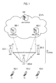
- Fig. 1 is a configuration diagram of the LTE system according to the present embodiment.
- the LTE system includes a plurality of UEs (User Equipments) 100, E-UTRAN (Evolved Universal Terrestrial Radio Access Network) 10, and EPC (Evolved Packet Core) 20.
- the E-UTRAN 10 and the EPC 20 constitute a network.
- the UE 100 is a mobile radio communication device and performs radio communication with a cell (a serving cell) with which a connection is established.
- the UE 100 corresponds to the user terminal.
- the E-UTRAN 10 includes a plurality of eNBs 200 (evolved Node-Bs).
- the eNB 200 corresponds to a base station.
- the eNB 200 controls a cell and performs radio communication with the UE 100 that establishes a connection with the cell.
- the "cell” is used as a term indicating a minimum unit of a radio communication area, and is also used as a term indicating a function of performing radio communication with the UE 100.
- the eNB 200 for example, has a radio resource management (RRM) function, a routing function of user data, and a measurement control function for mobility control and scheduling.
- RRM radio resource management
- the EPC 20 includes a MME (Mobility Management Entity)/S-GWs (Serving-Gateways) 300 and an AAA server 400.
- MME Mobility Management Entity
- S-GWs Server-Gateways
- AAA server 400 AAA server
- the MME is a network node for performing various mobility controls, for example, for the UE 100 and corresponds to a controller.
- the S-GW is a network node that performs transfer control of user data and corresponds to a mobile switching center.
- the eNBs 200 are connected mutually via an X2 interface. Furthermore, the eNB 200 is connected to the MME/S-GW 300 via an S1 interface.
- the AAA server 400 is a server device that performs authentication, authorization, and accounting.
- Fig. 2 is a block diagram of the UE 100.
- the UE 100 includes an antenna 101, a radio transceiver 110, a user interface 120, a GNSS (Global Navigation Satellite System) receiver 130, a battery 140, a memory 150, and a processor 160.
- the memory 150 and the processor 160 constitute a control unit.
- the UE 100 may not have the GNSS receiver 130. Furthermore, the memory 150 may be integrally formed with the processor 160, and this set (that is, a chipset) may be called a processor 160'.
- the antenna 101 and the radio transceiver 110 are used to transmit and receive a radio signal.
- the antenna 101 includes a plurality of antenna elements.
- the radio transceiver 110 converts a baseband signal output from the processor 160 into the radio signal, and transmits the radio signal from the antenna 101. Furthermore, the radio transceiver 110 converts the radio signal received by the antenna 101 into the baseband signal, and outputs the baseband signal to the processor 160.
- the user interface 120 is an interface with a user carrying the UE 100, and includes, for example, a display, a microphone, a speaker, and various buttons.
- the user interface 120 receives an operation from a user and outputs a signal indicating the content of the operation to the processor 160.
- the GNSS receiver 130 receives a GNSS signal in order to obtain location information indicating a geographical location of the UE 100, and outputs the received signal to the processor 160.
- the battery 140 accumulates a power to be supplied to each block of the UE 100.
- the memory 150 stores a program to be executed by the processor 160 and information to be used for a process by the processor 160.
- the processor 160 includes a baseband processor that performs modulation and demodulation, encoding and decoding and the like of the baseband signal, and a CPU (Central Processing Unit) that performs various processes by executing the program stored in the memory 150.
- the processor 160 may further include a codec that performs coding and decoding of sound and video signals.
- the processor 160 implements various processes and various communication protocols described later.
- Fig. 3 is a block diagram of the eNB 200.
- the eNB 200 includes an antenna 201, a radio transceiver 210, a network interface 220, a memory 230, and a processor 240.
- the memory 230 and the processor 240 constitute a control unit.
- the memory 230 may be integrally formed with the processor 240, and this set (that is, a chipset) may be called a processor.
- the antenna 201 and the radio transceiver 210 are used to transmit and receive a radio signal.
- the antenna 201 includes a plurality of antenna elements.
- the radio transceiver 210 converts the baseband signal output from the processor 240 into the radio signal, and transmits the radio signal from the antenna 201. Furthermore, the radio transceiver 210 converts the radio signal received by the antenna 201 into the baseband signal, and outputs the baseband signal to the processor 240.
- the network interface 220 is connected to the neighboring eNB 200 via the X2 interface and is connected to the MME/S-GW 300 via the S1 interface.
- the network interface 220 is used in communication performed on the X2 interface and communication performed on the S1 interface.
- the memory 230 stores a program to be executed by the processor 240 and information to be used for a process by the processor 240.
- the processor 240 includes the baseband processor that performs modulation and demodulation, encoding and decoding and the like of the baseband signal and a CPU that performs various processes by executing the program stored in the memory 230.
- the processor 240 implements various processes and various communication protocols described later.
- Fig. 4 is a protocol stack diagram of a radio interface in the LTE system.
- the radio interface protocol is classified into a layer 1 to a layer 3 of an OSI reference model, wherein the layer 1 is a physical (PHY) layer.
- the layer 2 includes a MAC (Media Access Control) layer, an RLC (Radio Link Control) layer, and a PDCP (Packet Data Convergence Protocol) layer.
- the layer 3 includes an RRC (Radio Resource Control) layer.
- the PHY layer performs encoding and decoding, modulation and demodulation, antenna mapping and demapping, and resource mapping and demapping. Between the PHY layer of the UE 100 and the PHY layer of the eNB 200, data is transmitted via the physical channel.
- the MAC layer performs preferential control of data, and a retransmission process and the like by hybrid ARQ (an HARQ). Between the MAC layer of the UE 100 and the MAC layer of the eNB 200, data is transmitted via a transport channel.
- the MAC layer of the eNB 200 includes a scheduler that determines an uplink and downlink transport format (a transport block size, a modulation and coding scheme and the like) and an assignment resource block.
- the RLC layer transmits data to an RLC layer of a reception side by using the functions of the MAC layer and the PHY layer. Between the RLC layer of the UE 100 and the RLC layer of the eNB 200, data is transmitted via a logical channel.
- the PDCP layer performs header compression and decompression, and encryption and decryption.
- the RRC layer is defined only in a control plane. Between the RRC layer of the UE 100 and the RRC layer of the eNB 200, a control message (an RRC message) for various types of setting is transmitted.
- the RRC layer controls the logical channel, the transport channel, and the physical channel in response to establishment, re-establishment, and release of a radio bearer.
- an RRC connection is established between the RRC of the UE 100 and the RRC of the eNB 200, the UE 100 is in a connection state, and when the RRC connection is not established, the UE 100 is in an idle state.
- a NAS (Non-Access Stratum) layer positioned above the RRC layer performs session management or mobility management, for example.
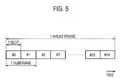
- Fig. 5 is a configuration diagram of a radio frame used in the LTE system.
- OFDMA Orthogonal Frequency Division Multiplexing Access
- SC-FDMA Single Carrier Frequency Division Multiple Access
- the radio frame is configured by 10 subframes arranged in a time direction, wherein each subframe is configured by two slots arranged in the time direction.
- Each subframe has a length of 1 ms and each slot has a length of 0.5 ms.
- Each subframe includes a plurality of resource blocks (RBs) in a frequency direction, and a plurality of symbols in the time direction. Each symbol is provided at a head thereof with a guard interval called a cyclic prefix (CP).
- the resource block includes a plurality of subcarriers in the frequency direction.
- a frequency resource can be designated by a resource block and a time resource can be designated by a subframe (or slot).
- an interval of several symbols at the head of each subframe is a control region mainly used as a physical downlink control channel (PDCCH). Furthermore, the other interval of each subframe is a region mainly used as a physical downlink shared channel (PDSCH). Moreover, in each subframe, cell-specific reference signals (CRSs) are distributed and arranged.
- PDCCH physical downlink control channel
- PDSCH physical downlink shared channel
- CRSs cell-specific reference signals
- both end portions in the frequency direction of each subframe are control regions mainly used as a physical uplink control channel (PUCCH). Furthermore, the center portion, in the frequency direction, of each subframe is a region mainly used as a physical uplink shared channel (PUSCH).
- PUCCH physical uplink control channel
- PUSCH physical uplink shared channel
- the LTE system supports the D2D communication.
- the D2D communication will be described in comparison with normal communication (cellular communication) of the LTE system.
- cellular communication data communication is performed between the network (the eNB 200) and the UE 100.
- the D2D communication data communication is directly performed among two or more UEs 100.
- Fig. 6 illustrates a data path in the cellular communication.
- Fig. 6 illustrates the case in which the cellular communication is performed between UE 100-1 that establishes a connection with eNB 200-1 and UE 100-2 that establishes a connection with eNB 200-2.
- the data path indicates a transfer path of user data (a user plane).
- the data path of the cellular communication goes through a network (a core network). Specifically, the data path is set to pass through the eNB 200-1, the S-GW 300, and the eNB 200-2.
- Fig. 7 illustrates a data path in the D2D communication.
- Fig. 7 illustrates the case in which the D2D communication is performed between the UE 100-1 that establishes a connection with the eNB 200-1 and the UE 100-2 that establishes a connection with the eNB 200-2.
- the data path of the D2D communication does not pass through the network. That is, direct radio communication is performed between UEs. As described above, when the UE 100-2 exists in the vicinity of the UE 100-1, the D2D communication is performed between the UE 100-1 and the UE 100-2, thereby obtaining an effect such as a traffic load on the network and a battery consumption amount of the UE 100 are reduced.
- cases in which the D2D communication is started include (a) a case in which the D2D communication is started after a partner terminal is discovered by performing an operation for discovering a partner terminal, and (b) a case in which the D2D communication is started without performing an operation for discovering a partner terminal.
- one UE 100 of the UE 100-1 and the UE 100-2 discovers the other UE 100 existing in the proximity of the one UE 100, so that the D2D communication is started.
- the UE 100 in order to discover the proximal terminal, the UE 100 has a (Discover) function of discovering another UE 100 existing in the proximity of the UE 100, and/or a (Discoverable) function of being discovered by another UE 100.
- one UE of the UE 100-1 and the UE 100-2 transmits a signal for discovery (Discover signal) to the vicinity of the one UE, and the other UE receives the signal for discovery, so that the other UE discovers the one UE. Furthermore, the other UE transmits a response signal for the signal for discovery to the vicinity of the other UE and the one UE receives the response signal, so that the one UE discovers the other UE.
- Discover signal Discover signal
- the UE 100 need not necessarily perform the D2D communication even upon discovering a partner terminal. For example, after mutually discovering each other, the UE 100-1 and the UE 100-2 may perform a negotiation, and determine whether or not to perform the D2D communication. When each of the UE 100-1 and the UE 100-2 agrees to perform the D2D communication, the D2D communication starts.
- the UE 100-1 starts broadcasting a signal for the D2D communication.
- the UE 100 is capable of starting the D2D communication regardless of the existence of the discovery of a partner terminal.
- the D2D communication is considered to be performed in a frequency band (that is, in a frequency band of the cellular communication) of the LTE system, and for example, in order to avoid interference to the cellular communication, the D2D communication is performed under the control of the network (the eNB 200).
- Fig. 8 is a diagram for explaining an operation environment according to the present embodiment.
- the UE 100-1 When starting the D2D communication with the UE 100-2, the UE 100-1 notifies the eNB 200 of the amount of specific data transmitted preferably in the D2D communication.
- the UE 100-2 when starting the D2D communication with the UE 100-1, notifies the eNB 200 of the amount of specific data transmitted preferably in the D2D communication.
- the specific data is data that is addressed to a communication partner in the D2D communication and corresponds to a predetermined application.
- the predetermined application is an application commensurate with the D2D communication, and for example, indicates an application requiring low delay or an application requiring large data capacity.
- the specific data may be data that is addressed to a communication partner in the D2D communication and data requiring predetermined service quality (QoS; Quality of Service).
- QoS predetermined service quality
- the predetermined service quality (QoS) is high service quality, and for example, indicates data that is transmitted through a bearer in which QCI (QoS Class Identifier) is equal to or more than a predetermined value.
- QCI is an index indicating priority determined in response to the presence or absence of transmission rate guarantee, a delay permission time, an acceptable packet loss rate and the like.
- the UE 100-1 when the UE 100-1 notifies the eNB 200 of a desire for performing the D2D communication, the UE 100-1 notifies the eNB 200 of the amount of specific data corresponding to oneself. In the same manner, when the UE 100-2 notifies the eNB 200 of a desire for performing the D2D communication, the UE 100-2 notifies the eNB 200 of the amount of specific data corresponding to oneself.
- the radio state report is a report (Measurement report) including information indicating a measurement result of a reception state of a reference signal received in the UE 100 from the eNB 200.
- a measurement result for example, indicates reference signal received power (RSRP) and reference signal received quality (RSRQ).
- the eNB 200 When it has been determined to permit the D2D communication, the eNB 200 assigns a radio resource to the D2D communication on the basis of the amount of the specific data corresponding to each of the UE 100-1 and the UE 100-2. Then, the eNB 200 notifies at least one of the UE 100-1 and the UE 100-2 of D2D resource information indicating the radio resource that is assigned to the D2D communication.
- the D2D resource information includes at least one of a number of a subframe that is assigned to the D2D communication, a time range that is assigned to the D2D communication, and a number of a resource block that is assigned to the D2D communication.
- the time range, which is assigned to the D2D communication indicates a combination of a start subframe number and an end subframe number, or a timer value (a value indicating a period).
- the D2D resource information may include information indicating a number of a resource block to be used after a predetermined subframe from the notification of the D2D resource information, similarly to assignment resource information of the cellular communication.
- the UE 100 which has received the D2D resource information uses a resource block indicated by the D2D resource information for the D2D communication after the predetermined subframe from the notification of the D2D resource information.
- the UE 100-1 and the UE 100-2 perform the D2D communication by using the radio resource that is assigned to the D2D communication by the eNB 200.
- the eNB 200 is able to reassign a radio resource for transmitting the remaining specific data.
- the AAA server 400 performs accounting for the D2D communication on the basis of at least one of: the amount of the specific data, which is notified from each of the UE 100-1 and the UE 100-2 to the eNB; and the amount of the radio resource that is assigned to the D2D communication.
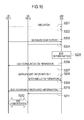
- Fig. 9 is an operation sequence diagram according to the present embodiment.
- the present sequence indicates an operation after the UE 100-1 and the UE 100-2 determined to start the D2D communication through the aforementioned discovery process.
- the UE 100-1 transmits a notification (Indication) indicating a desire for performing the D2D communication to the eNB 200. Furthermore, the UE 100-1 includes data amount information 1 indicating the amount of specific data transmitted preferably in the D2D communication, into the notification, and transmits the notification.
- the notification Indication
- the eNB 200 recognizes the amount of specific data corresponding to the UE 100-1 from the data amount information 1 included in the notification.
- the UE 100-2 transmits a notification (Indication) indicating a desire for performing the D2D communication to the eNB 200. Furthermore, the UE 100-2 includes data amount information 2 indicating the amount of specific data transmitted preferably in the D2D communication, into the notification, and transmits the notification.
- the notification Indication
- the eNB 200 recognizes the amount of specific data corresponding to the UE 100-2 from the data amount information 2 included in the notification.
- step S103 the UE 100-1 transmits a reception state report (Measurement report) to the eNB 200 on the basis of a reference signal that is received from the eNB 200.
- a reception state report (Measurement report)
- the eNB 200 recognizes a radio state corresponding to the UE 100-1.
- step S104 the UE 100-2 transmits a reception state report (Measurement report) to the eNB 200 on the basis of the reference signal that is received from the eNB 200.
- a reception state report (Measurement report)
- the eNB 200 recognizes a radio state corresponding to the UE 100-2.
- step S105 the eNB 200 determines whether to permit the D2D communication by the UE 100-1 and the UE 100-2 on the basis of the amount of the specific data corresponding to each of the UE 100-1 and the UE 100-2, and the radio states corresponding to each of the UE 100-1 and the UE 100-2. For example, when received power of the reference signal received in each of the UE 100-1 and the UE 100-2 from the eNB 200 is high, the eNB 200 may reject the D2D communication in order to avoid interference from the D2D communication by the UE 100-1 and the UE 100-2.
- the eNB 200 may regard that the necessity of starting the D2D communication is low and reject the D2D communication.
- a description will be given on the assumption that the eNB 200 has permitted the D2D communication.
- the eNB 200 determines a radio resource that is assigned to the D2D communication by the UE 100-1 and the UE 100-2. For example, as the amount of the specific data corresponding to each of the UE 100-1 and the UE 100-2 is large, the eNB 200 increases the amount of the radio resource that is assigned to the D2D communication.
- the eNB 200 transmits, to the UE 100-1, a notification (D2D communication permission) indicating that the D2D communication is permitted. Furthermore, the eNB 200 includes D2D assignment resource information, which indicates the radio resource to be assigned to the D2D communication by the UE 100-1 and the UE 100-2, into the notification (the D2D communication permission), and transmits the notification. When the D2D communication permission is received, the UE 100-1 recognizes the radio resource assigned to the D2D communication from the D2D assignment resource information included in the D2D communication permission.
- the eNB 200 transmits, to the UE 100-2, a notification (D2D communication permission) indicating that the D2D communication is permitted. Furthermore, the eNB 200 includes D2D assignment resource information, which indicates the radio resource to be assigned to the D2D communication by the UE 100-1 and the UE 100-2, into the notification (the D2D communication permission), and transmits the notification. When the D2D communication permission is received, the UE 100-2 recognizes the radio resource assigned to the D2D communication from the D2D assignment resource information included in the D2D communication permission.
- step S108 the UE 100-1 and the UE 100-2 perform the D2D communication by using the radio resource assigned from the eNB 200.
- the UE 100-1 and the UE 100-2 notify the eNB 200 of the remaining amount of specific data.
- the UE 100-1 and the UE 100-2 may notify the eNB 200 of the amount of data transmitted using a radio resource (a D2D assignment period of a previous time) assigned in a previous time.
- the AAA server 400 performs accounting for the D2D communication on the basis of at least one of: the amount of the specific data, which is notified from each of the UE 100-1 and the UE 100-2 to the eNB; and the amount of the radio resource that is assigned to the D2D communication. Moreover, the AAA server 400 may use the amount of the data, which was transmitted using the radio resource (the D2D assignment period of the previous time) assigned in the previous time and is notified from each of the UE 100-1 and the UE 100-2 to the eNB 200, for the accounting.
- a communication environment according to the second embodiment is the same as that of the first embodiment.
- each of the UE 100-1 and the UE 100-2 when notifying the eNB 200 of the desire for performing the D2D communication, each of the UE 100-1 and the UE 100-2 notifies the eNB 200 of the amount of the specific data corresponding to oneself.
- each of the UE 100-1 and the UE 100-2 after the permission of the D2D communication is notified from the eNB 200, each of the UE 100-1 and the UE 100-2 notifies the eNB 200 of the amount of specific data.
- Fig. 10 is an operation sequence diagram according to the present embodiment.
- step S201 the UE 100-1 transmits a notification (Indication) indicating a desire for performing the D2D communication to the eNB 200.
- a notification Indication
- step S202 the UE 100-2 transmits a notification (Indication) indicating a desire for performing the D2D communication to the eNB 200.
- a notification Indication
- step S203 the UE 100-1 transmits a reception state report (Measurement report) to the eNB 200 on the basis of a reference signal that is received from the eNB 200.
- a reception state report (Measurement report)
- the eNB 200 recognizes a radio state corresponding to the UE 100-1.
- step S204 the UE 100-2 transmits a reception state report (Measurement report) to the eNB 200 on the basis of the reference signal that is received from the eNB 200.
- a reception state report (Measurement report)
- the eNB 200 recognizes a radio state corresponding to the UE 100-2.
- the eNB 200 determines whether to permit the D2D communication by the UE 100-1 and the UE 100-2 on the basis of the radio states corresponding to each of the UE 100-1 and the UE 100-2. For example, when received power of the reference signal received in each of the UE 100-1 and the UE 100-2 from the eNB 200 is high, the eNB 200 may reject the D2D communication in order to avoid interference from the D2D communication by the UE 100-1 and the UE 100-2.
- a description will be given on the assumption that the eNB 200 has permitted the D2D communication.
- step S206 the eNB 200 transmits, to the UE 100-1, a notification (D2D communication permission) indicating that the D2D communication is permitted.
- a notification D2D communication permission
- step S207 the eNB 200 transmits, to the UE 100-2, a notification (D2D communication permission) indicating that the D2D communication is permitted.
- a notification D2D communication permission
- step S208 the UE 100-1 transmits, to the eNB 200, the data amount information 1 indicating the amount of specific data transmitted preferably in the D2D communication, in response to the reception of the notification (D2D communication permission) in step S206.
- the eNB 200 recognizes the amount of the specific data corresponding to the UE 100-1.
- step S209 the UE 100-2 transmits, to the eNB 200, the data amount information 2 indicating the amount of specific data transmitted preferably in the D2D communication, in response to the reception of the notification (D2D communication permission) in step S207.
- the eNB 200 recognizes the amount of the specific data corresponding to the UE 100-2.
- the eNB 200 determines a radio resource that is assigned to the D2D communication by the UE 100-1 and the UE 100-2. For example, as the amount of the specific data corresponding to each of the UE 100-1 and the UE 100-2 is large, the eNB 200 increases the amount of the radio resource that is assigned to the D2D communication.
- step S210 the eNB 200 transmits, to the UE 100-1, D2D assignment resource information indicating the radio resource that is assigned to the D2D communication by the UE 100-1 and the UE 100-2.
- the UE 100-1 recognizes the radio resource assigned to the D2D communication.
- step S211 the eNB 200 transmits, to the UE 100-2, the D2D assignment resource information indicating the radio resource that is assigned to the D2D communication by the UE 100-1 and the UE 100-2.
- the UE 100-2 recognizes the radio resource assigned to the D2D communication.
- step S212 the UE 100-1 and the UE 100-2 perform the D2D communication by using the radio resource assigned from the eNB 200.
- the subsequent operation is the same as that of the first embodiment.
- a communication environment according to the third embodiment is the same as that of the first embodiment.
- each of the UE 100-1 and the UE 100-2 notifies the eNB 200 of the amount of the specific data corresponding to oneself.
- the UE 100-2 notifies the UE 100-1 of the amount of specific data transmitted preferably in the D2D communication.
- the UE 100-1 notifies the eNB 200 of the amount of specific data corresponding to the UE 100-1 and also notifies the eNB 200 of the amount of specific data corresponding to the UE 100-2.
- the UE 100-1 performs communication (specifically, communication of a control plane) with the eNB 200 as a representative of a UE group (the UE 100-1 and the UE 100-2), which is an object of the D2D communication, and performs control of the D2D communication.
- UE group the UE 100-1 and the UE 100-2
- anchor UE Such UE 100-1 may be called “anchor UE”.
- FIG. 11 is an operation sequence diagram according to the present embodiment.
- the UE 100-2 notifies the UE 100-1 of the data amount information 2 indicating the amount of specific data transmitted preferably in the D2D communication. Furthermore, the UE 100-2 may control the data amount information 2 to be included into a signal for discovery for discovering a communication partner in the D2D communication, and notify the UE 100-1 of the data amount information 2.
- the UE 100-1 transmits a notification (Indication) indicating a desire for performing the D2D communication to the eNB 200. Furthermore, the UE 100-1 includes the data amount information 1 indicating the amount of specific data transmitted preferably in the D2D communication, into the notification (Indication), and transmits the notification. Moreover, the UE 100-1 includes the data amount information 2 notified from the UE 100-2, into the notification (Indication), and transmits the notification.
- the notification (Indication) is received from the UE 100-1
- the eNB 200 recognizes the amount of specific data corresponding to each of the UE 100-1 and the UE 100-2 from the data amount information 1 and 2 included in the notification.
- step S303 the UE 100-1 transmits a reception state report (Measurement report) to the eNB 200 on the basis of a reference signal that is received from the eNB 200.
- a reception state report (Measurement report)
- the eNB 200 recognizes a radio state corresponding to the UE 100-1.
- step S304 the UE 100-2 transmits a reception state report (Measurement report) to the eNB 200 on the basis of the reference signal that is received from the eNB 200.
- a reception state report (Measurement report)
- the eNB 200 recognizes a radio state corresponding to the UE 100-2.
- step S305 the eNB 200 determines whether to permit the D2D communication by the UE 100-1 and the UE 100-2 on the basis of the amount of the specific data corresponding to each of the UE 100-1 and the UE 100-2, and the radio states corresponding to each of the UE 100-1 and the UE 100-2.
- a description will be given on the assumption that the eNB 200 has permitted the D2D communication.
- the eNB 200 determines a radio resource that is assigned to the D2D communication by the UE 100-1 and the UE 100-2.
- the eNB 200 transmits, to the UE 100-1, a notification (D2D communication permission) indicating that the D2D communication is permitted. Furthermore, the eNB 200 includes D2D assignment resource information, which indicates the radio resource to be assigned to the D2D communication by the UE 100-1 and the UE 100-2, into the notification (the D2D communication permission), and transmits the notification. When the D2D communication permission is received, the UE 100-1 recognizes the radio resource assigned to the D2D communication from the D2D assignment resource information included in the D2D communication permission.
- step S307 the UE 100-1 and the UE 100-2 perform the D2D communication by using the radio resource assigned from the eNB 200.
- the subsequent operation is the same as that of the first embodiment, but is different from the first embodiment in the following point.
- the UE 100-2 When it is not possible to transmit the amount of the specific data, which corresponds to the UE 100-2, in a range of the radio resource that is assigned to the D2D communication, the UE 100-2 notifies the UE 100-1 of the remaining amount of specific data.
- the UE 100-2 may notify the UE 100-1 of the amount of data transmitted using a radio resource assigned in a previous time.
- the UE 100-1 notifies the eNB 200 of the remaining amount (and the amount of the data transmitted using the radio resource assigned in the previous time) of the specific data notified from the UE 100-2.
- a communication environment according to the fourth embodiment is the same as that according to the first embodiment. Furthermore, the fourth embodiment is the same as the third embodiment in that anchor UE exists.
- the UE 100-1 when notifying the eNB 200 of the desire for performing the D2D communication, the UE 100-1 notifies the eNB 200 of the amount of specific data.
- the UE 100-1 after the permission of the D2D communication is notified from the eNB 200, the UE 100-1 notifies the eNB 200 of the amount of specific data.
- Fig. 12 is an operation sequence diagram according to the present embodiment.
- the UE 100-2 notifies the UE 100-1 of the data amount information 2 indicating the amount of specific data transmitted preferably in the D2D communication. Furthermore, the UE 100-2 may control the data amount information 2 to be included into a signal for discovery for discovering a communication partner in the D2D communication, and notify the UE 100-1 of the data amount information 2.
- step S402 the UE 100-1 transmits a notification (Indication) indicating a desire for performing the D2D communication to the eNB 200.
- a notification Indication
- step S403 the UE 100-1 transmits a reception state report (Measurement report) to the eNB 200 on the basis of a reference signal that is received from the eNB 200.
- a reception state report (Measurement report)
- the eNB 200 recognizes a radio state corresponding to the UE 100-1.
- step S404 the UE 100-2 transmits a reception state report (Measurement report) to the eNB 200 on the basis of the reference signal that is received from the eNB 200.
- a reception state report (Measurement report)
- the eNB 200 recognizes a radio state corresponding to the UE 100-2.
- step S405 the eNB 200 determines whether to permit the D2D communication by the UE 100-1 and the UE 100-2 on the basis of the radio states corresponding to each of the UE 100-1 and the UE 100-2.
- a description will be given on the assumption that the eNB 200 has permitted the D2D communication.
- step S406 the eNB 200 transmits, to the UE 100-1, a notification (D2D communication permission) indicating that the D2D communication is permitted.
- a notification D2D communication permission
- step S407 the UE 100-1 transmits, to the eNB 200, the data amount information 1 indicating the amount of specific data transmitted preferably in the D2D communication, and the data amount information 2 notified from the UE 100-2.
- the eNB 200 recognizes the amount of the specific data corresponding to each of the UE 100-1 and the UE 100-2.
- the eNB 200 determines a radio resource that is assigned to the D2D communication by the UE 100-1 and the UE 100-2.
- step S408 the eNB 200 transmits, to the UE 100-1, D2D assignment resource information indicating the radio resource that is assigned to the D2D communication by the UE 100-1 and the UE 100-2.
- the UE 100-1 recognizes the radio resource assigned to the D2D communication.
- step S409 the UE 100-1 and the UE 100-2 perform the D2D communication by using the radio resource assigned from the eNB 200.
- the subsequent operation is the same as that of the third embodiment.
- the present embodiment has described an example in which the UE 100-2 controls the data amount information 2 to be included into the signal for discovery, thereby notifying the UE 100-1 of the data amount information 2.
- the data amount information 2 may be acquired from the UE 100-2 after the UE 100-1 receives the D2D communication permission from the eNB 200.
- the aforementioned first embodiment to fourth embodiment do not particularly consider transmission power according to the D2D communication.
- the following operations may also be applied in addition to the aforementioned operations (or instead of the aforementioned operations).
- the UE 100-1 determines transmission power (hereinafter, "required transmission power of D2D communication") required for performing the D2D communication with a communication partner UE on the basis of received power of a signal for discovery, received power of a response signal for the signal for discovery, and the like.
- the UE 100-1 when transmitting a notification (Indication) indicating a desire for performing the D2D communication, the UE 100-1 (and the UE 100-2) also notifies the required transmission power of the D2D communication. For example, the UE 100-1 (and the UE 100-2) controls information on the required transmission power of the D2D communication to be included into the notification (Indication).
- the eNB 200 when determining whether to permit the D2D communication, the eNB 200 also considers the required transmission power of the D2D communication in order to avoid interference to cellular communication from the D2D communication. For example, when the required transmission power of the D2D communication is higher than transmission power of the UE 100-1 (and the UE 100-2) in the cellular communication, which is estimated in the eNB 200, the eNB 200 may reject the D2D communication.
- the UE 100-1 when notifying the eNB 200 of the remaining amount of specific data, which may not be transmitted in a range of an assignment radio resource (that is, when requesting reassignment of a radio resource for the D2D communication), the UE 100-1 (and the UE 100-2) also notifies current transmission power of the D2D communication. For example, the UE 100-1 (and the UE 100-2) controls information on the current transmission power of the D2D communication to be included into the notification or the request.
- the eNB 200 determines whether to permit the continuance of the D2D communication. For example, when the current transmission power of the D2D communication is higher than the transmission power of the UE 100-1 (and the UE 100-2) in the cellular communication, which is estimated in the eNB 200, the eNB 200 may reject the continuance of the D2D communication.
- the aforementioned third embodiment and fourth embodiment have described an example in which the UE 100-2 controls the data amount information 2 to be included into the signal for discovery, thereby notifying the UE 100-1 of the data amount information 2.
- the UE 100-1 may control the data amount information 1 to be included into the signal for discovery, thereby notifying the UE 100-2 of the data amount information 1.
- the data amount information may be included into the signal for discovery.
- the eNB 200 determines the radio resource that is assigned to the D2D communication by the UE 100-1 and the UE 100-2 on the basis of the amount of the specific data corresponding to each of the UE 100-1 and the UE 100-2.
- the eNB 200 may determine the radio resource that is assigned to the D2D communication by the UE 100-1 and the UE 100-2 on the basis of the radio states corresponding to each of the UE 100-1 and the UE 100-2 and the amount of the specific data corresponding to each of the UE 100-1 and the UE 100-2.
- the eNB 200 may determine that it is possible to increase the amount of the radio resource that is assigned to the D2D communication.
- the eNB 200 controls the D2D communication; however, this configuration is not restrictive.
- an upper network node (such as the MME) constituting the core network controls the D2D communication according to the present embodiments instead of the eNB 200.
- the network node may receive information (such as the data amount information) from the UE 100 via the eNB 200 and transmit information (such as the notification indicating that the D2D communication is permitted) to the UE 100 via the eNB 200.
- a network device such as the eNB 200 and the MME performs the control relevant to the D2D communication.
- a direct communication mode in which the data pass does not pass through the eNB 200 is.
- a local relay mode in which the data pass passes through the eNB 200 may be.
- the local relay mode is called a Locally Routed (L. R) mode.
- the aforementioned embodiments have described an example in which the present invention is applied to the LTE system.
- the present invention is not limited to the LTE system, and the present invention may also be applied to systems, other than the LTE system, as well as the LTE system.
- the present invention according to the mobile communication system, the user terminal, the base station, the processor and the communication control method are possible to appropriately control the D2D communication, and thus they are useful in a mobile communication field.
Landscapes
- Engineering & Computer Science (AREA)
- Computer Networks & Wireless Communication (AREA)
- Signal Processing (AREA)
- Mobile Radio Communication Systems (AREA)
Applications Claiming Priority (2)
| Application Number | Priority Date | Filing Date | Title |
|---|---|---|---|
| US201261719604P | 2012-10-29 | 2012-10-29 | |
| PCT/JP2013/077815 WO2014069221A1 (fr) | 2012-10-29 | 2013-10-11 | Système de communication mobile, terminal utilisateur, station de base, processeur et procédé de commande de communications |
Publications (3)
| Publication Number | Publication Date |
|---|---|
| EP2914054A1 true EP2914054A1 (fr) | 2015-09-02 |
| EP2914054A4 EP2914054A4 (fr) | 2016-07-13 |
| EP2914054B1 EP2914054B1 (fr) | 2018-05-16 |
Family
ID=50627135
Family Applications (1)
| Application Number | Title | Priority Date | Filing Date |
|---|---|---|---|
| EP13851802.2A Active EP2914054B1 (fr) | 2012-10-29 | 2013-10-11 | Système de communication mobile, station de base, processeur et procédé de commande de communications |
Country Status (4)
| Country | Link |
|---|---|
| US (3) | US9763273B2 (fr) |
| EP (1) | EP2914054B1 (fr) |
| JP (2) | JP6087370B2 (fr) |
| WO (1) | WO2014069221A1 (fr) |
Cited By (2)
| Publication number | Priority date | Publication date | Assignee | Title |
|---|---|---|---|---|
| EP3179756A4 (fr) * | 2014-08-06 | 2017-11-01 | Fujitsu Limited | Système de communication, procédé de communication, dispositif de communication et terminal mobile |
| CN107846708A (zh) * | 2016-09-19 | 2018-03-27 | 中国移动通信有限公司研究院 | V2x数据传输方法及装置 |
Families Citing this family (9)
| Publication number | Priority date | Publication date | Assignee | Title |
|---|---|---|---|---|
| EP2768270A1 (fr) * | 2013-02-14 | 2014-08-20 | Alcatel Lucent | Procédé permettant d'établir une communication directe terminal à terminal avec l'aide du réseau, des stations de base, une passerelle et un dispositif associé |
| KR101831084B1 (ko) * | 2013-10-03 | 2018-02-21 | 엘지전자 주식회사 | 무선 통신 시스템에서 d2d 동작을 위한 자원을 사용하는 방법 및 장치 |
| JP6649712B2 (ja) * | 2014-07-25 | 2020-02-19 | 住友電気工業株式会社 | 制御装置、無線装置、及び無線通信装置 |
| EP3190844B1 (fr) * | 2014-09-26 | 2019-07-24 | Huawei Technologies Co., Ltd. | Procédé à sauts de fréquence pour signal d2d, et station de base |
| US10568154B2 (en) | 2015-03-06 | 2020-02-18 | Nec Corporation | Apparatus and method for proximity-based service communication |
| WO2016163471A1 (fr) | 2015-04-10 | 2016-10-13 | 京セラ株式会社 | Station de base et terminal sans fil |
| US11368872B2 (en) * | 2017-03-27 | 2022-06-21 | Nec Corporation | Communication apparatus, base station, radio resource allocation method, and computer readable medium |
| CN111615143B (zh) * | 2019-05-09 | 2022-02-25 | 维沃移动通信有限公司 | 信息上报方法、信息接收方法、终端和网络控制实体 |
| JP7061254B2 (ja) | 2020-05-12 | 2022-04-28 | 株式会社シプソル | 梱包システム |
Citations (3)
| Publication number | Priority date | Publication date | Assignee | Title |
|---|---|---|---|---|
| WO2012049351A1 (fr) * | 2010-10-13 | 2012-04-19 | Nokia Corporation | Sélection de mode de communication |
| WO2012073846A1 (fr) * | 2010-11-30 | 2012-06-07 | 株式会社エヌ・ティ・ティ・ドコモ | Procédé de communication mobile, station de base sans fil et station mobile |
| WO2012091420A2 (fr) * | 2010-12-27 | 2012-07-05 | 한국전자통신연구원 | Procédé pour établir une connexion via une liaison de dispositif à dispositif, pour programmer une communication de dispositif à dispositif et pour relayer un terminal |
Family Cites Families (17)
| Publication number | Priority date | Publication date | Assignee | Title |
|---|---|---|---|---|
| WO2006106634A1 (fr) * | 2005-03-31 | 2006-10-12 | Pioneer Corporation | Systeme de reseau radio local, station de base et station terminale dudit systeme |
| CA2625623A1 (fr) * | 2005-11-11 | 2007-05-18 | Telefonaktiebolaget L M Ericsson (Publ) | Procede et appareil permettant de limiter les interferences lors de la communication de poste a poste |
| KR101296021B1 (ko) * | 2008-10-29 | 2013-08-12 | 노키아 코포레이션 | 무선 통신 시스템에서의 디바이스 대 디바이스 통신을 위한 동적 통신 자원 할당을 위한 장치 및 방법 |
| US8606289B2 (en) * | 2008-11-10 | 2013-12-10 | Qualcomm Incorporated | Power headroom-sensitive scheduling |
| US8761099B2 (en) * | 2009-01-16 | 2014-06-24 | Nokia Corporation | Apparatus and method of scheduling resources for device-to-device communications |
| US8977232B2 (en) * | 2009-01-29 | 2015-03-10 | Qualcomm Incorporated | Certified device-based accounting |
| WO2010102668A1 (fr) * | 2009-03-12 | 2010-09-16 | Nokia Siemens Networks Oy | Communication de dispositif à dispositif |
| JP5522983B2 (ja) | 2009-06-23 | 2014-06-18 | キヤノン株式会社 | 通信装置、通信装置の制御方法 |
| JP2011055221A (ja) * | 2009-09-01 | 2011-03-17 | Hitachi Kokusai Electric Inc | 無線通信システム |
| WO2011069295A1 (fr) * | 2009-12-11 | 2011-06-16 | Nokia Corporation | Procédé, appareil et produit programme d'ordinateur pour l'allocation de ressources dans un réseau de communication sans fil |
| KR20120080327A (ko) * | 2011-01-07 | 2012-07-17 | 삼성전자주식회사 | 무선통신시스템에서 상향링크 송신전력을 제어하기 위한 방법 및 장치 |
| JP5318151B2 (ja) | 2011-04-22 | 2013-10-16 | 株式会社エヌ・ティ・ティ・ドコモ | 移動通信方法、無線基地局及び移動局 |
| EP2715981B1 (fr) * | 2011-06-01 | 2018-11-28 | NTT DoCoMo, Inc. | Accès local amélioré dans des communications mobiles |
| JP6360277B2 (ja) * | 2012-04-25 | 2018-07-18 | 株式会社Nttドコモ | 課金システム、課金装置及び課金方法 |
| TWI620459B (zh) * | 2012-05-31 | 2018-04-01 | 內數位專利控股公司 | 在蜂巢式通訊系統中賦能直鏈通訊排程及控制方法 |
| US9398630B2 (en) * | 2012-08-10 | 2016-07-19 | Alcatel Lucent | Methods and apparatuses for controlling and scheduling device-to-device communications |
| US11496948B2 (en) * | 2012-10-19 | 2022-11-08 | Samsung Electronics Co., Ltd. | System and method for ad-hoc/network assisted device discovery protocol for device to device communications |
-
2013
- 2013-10-11 WO PCT/JP2013/077815 patent/WO2014069221A1/fr active Application Filing
- 2013-10-11 JP JP2014544413A patent/JP6087370B2/ja active Active
- 2013-10-11 US US14/438,684 patent/US9763273B2/en active Active
- 2013-10-11 EP EP13851802.2A patent/EP2914054B1/fr active Active
-
2016
- 2016-09-21 JP JP2016184865A patent/JP6282705B2/ja active Active
-
2017
- 2017-09-11 US US15/700,622 patent/US10098162B2/en active Active
-
2018
- 2018-09-11 US US16/128,279 patent/US20190014558A1/en not_active Abandoned
Patent Citations (5)
| Publication number | Priority date | Publication date | Assignee | Title |
|---|---|---|---|---|
| WO2012049351A1 (fr) * | 2010-10-13 | 2012-04-19 | Nokia Corporation | Sélection de mode de communication |
| WO2012073846A1 (fr) * | 2010-11-30 | 2012-06-07 | 株式会社エヌ・ティ・ティ・ドコモ | Procédé de communication mobile, station de base sans fil et station mobile |
| US20130250798A1 (en) * | 2010-11-30 | 2013-09-26 | Ntt Docomo, Inc. | Mobile communication method, radio base station, and mobile station |
| WO2012091420A2 (fr) * | 2010-12-27 | 2012-07-05 | 한국전자통신연구원 | Procédé pour établir une connexion via une liaison de dispositif à dispositif, pour programmer une communication de dispositif à dispositif et pour relayer un terminal |
| US20140023008A1 (en) * | 2010-12-27 | 2014-01-23 | Jae-Young Ahn | Method for establishing a device-to-device link connection and scheduling for device-to-device communication and terminal relaying |
Non-Patent Citations (2)
| Title |
|---|
| None * |
| See also references of WO2014069221A1 * |
Cited By (3)
| Publication number | Priority date | Publication date | Assignee | Title |
|---|---|---|---|---|
| EP3179756A4 (fr) * | 2014-08-06 | 2017-11-01 | Fujitsu Limited | Système de communication, procédé de communication, dispositif de communication et terminal mobile |
| CN107846708A (zh) * | 2016-09-19 | 2018-03-27 | 中国移动通信有限公司研究院 | V2x数据传输方法及装置 |
| CN107846708B (zh) * | 2016-09-19 | 2021-11-19 | 中国移动通信有限公司研究院 | V2x数据传输方法及装置 |
Also Published As
| Publication number | Publication date |
|---|---|
| WO2014069221A1 (fr) | 2014-05-08 |
| US10098162B2 (en) | 2018-10-09 |
| EP2914054B1 (fr) | 2018-05-16 |
| JPWO2014069221A1 (ja) | 2016-09-08 |
| EP2914054A4 (fr) | 2016-07-13 |
| JP6087370B2 (ja) | 2017-03-01 |
| JP6282705B2 (ja) | 2018-02-21 |
| US20180014343A1 (en) | 2018-01-11 |
| US20190014558A1 (en) | 2019-01-10 |
| US20150257186A1 (en) | 2015-09-10 |
| JP2017022762A (ja) | 2017-01-26 |
| US9763273B2 (en) | 2017-09-12 |
Similar Documents
| Publication | Publication Date | Title |
|---|---|---|
| US10911999B2 (en) | Mobile communication system, user terminal, base station, processor, and communication control method | |
| US10299306B2 (en) | User terminal, processor, and base station | |
| US10098162B2 (en) | Mobile communication system, user terminal, base station, processor, and communication control method | |
| US9642172B2 (en) | Mobile communication system, base station, user terminal, and processor | |
| EP3668268A1 (fr) | Système de communication mobile, terminal utilisateur et station de base | |
| EP2961240A1 (fr) | Système de communication mobile, station de base, terminaux utilisateurs et processeur | |
| US10750480B2 (en) | Mobile communication system, user terminal, base station, processor, and communication control method | |
| EP2903393A1 (fr) | Système de communication mobile, station de base et terminal utilisateur | |
| EP2879453A1 (fr) | Système de communication mobile, dispositif utilisateur et processeur | |
| EP3101977A1 (fr) | Système de communication mobile et terminal d'utilisateur | |
| EP3051852A1 (fr) | Terminal utilisateur, dispositif de réseau et processeur | |
| US9560688B2 (en) | Mobile communication system, user terminal, communication control apparatus, and communication control method | |
| US9456463B2 (en) | Mobile communication system, user terminal, and communication control method | |
| US10200848B2 (en) | Communication control method, base station, and user terminal | |
| US20160212730A1 (en) | Network apparatus and user terminal |
Legal Events
| Date | Code | Title | Description |
|---|---|---|---|
| PUAI | Public reference made under article 153(3) epc to a published international application that has entered the european phase |
Free format text: ORIGINAL CODE: 0009012 |
|
| 17P | Request for examination filed |
Effective date: 20150430 |
|
| AK | Designated contracting states |
Kind code of ref document: A1 Designated state(s): AL AT BE BG CH CY CZ DE DK EE ES FI FR GB GR HR HU IE IS IT LI LT LU LV MC MK MT NL NO PL PT RO RS SE SI SK SM TR |
|
| AX | Request for extension of the european patent |
Extension state: BA ME |
|
| DAX | Request for extension of the european patent (deleted) | ||
| RA4 | Supplementary search report drawn up and despatched (corrected) |
Effective date: 20160609 |
|
| RIC1 | Information provided on ipc code assigned before grant |
Ipc: H04W 76/02 20090101AFI20160603BHEP Ipc: H04W 92/18 20090101ALI20160603BHEP Ipc: H04W 84/10 20090101ALI20160603BHEP |
|
| 17Q | First examination report despatched |
Effective date: 20170330 |
|
| REG | Reference to a national code |
Ref country code: DE Ref legal event code: R079 Ref document number: 602013037661 Country of ref document: DE Free format text: PREVIOUS MAIN CLASS: H04W0092180000 Ipc: H04W0076040000 |
|
| GRAP | Despatch of communication of intention to grant a patent |
Free format text: ORIGINAL CODE: EPIDOSNIGR1 |
|
| RIC1 | Information provided on ipc code assigned before grant |
Ipc: H04W 84/10 20090101ALI20171115BHEP Ipc: H04W 76/04 20090101AFI20171115BHEP Ipc: H04W 72/02 20090101ALI20171115BHEP Ipc: H04W 92/18 20090101ALI20171115BHEP Ipc: H04W 76/02 20090101ALI20171115BHEP |
|
| INTG | Intention to grant announced |
Effective date: 20171206 |
|
| GRAS | Grant fee paid |
Free format text: ORIGINAL CODE: EPIDOSNIGR3 |
|
| GRAA | (expected) grant |
Free format text: ORIGINAL CODE: 0009210 |
|
| RAP1 | Party data changed (applicant data changed or rights of an application transferred) |
Owner name: KYOCERA CORPORATION |
|
| AK | Designated contracting states |
Kind code of ref document: B1 Designated state(s): AL AT BE BG CH CY CZ DE DK EE ES FI FR GB GR HR HU IE IS IT LI LT LU LV MC MK MT NL NO PL PT RO RS SE SI SK SM TR |
|
| REG | Reference to a national code |
Ref country code: GB Ref legal event code: FG4D |
|
| REG | Reference to a national code |
Ref country code: CH Ref legal event code: EP |
|
| REG | Reference to a national code |
Ref country code: IE Ref legal event code: FG4D |
|
| REG | Reference to a national code |
Ref country code: DE Ref legal event code: R096 Ref document number: 602013037661 Country of ref document: DE |
|
| REG | Reference to a national code |
Ref country code: AT Ref legal event code: REF Ref document number: 1000701 Country of ref document: AT Kind code of ref document: T Effective date: 20180615 |
|
| REG | Reference to a national code |
Ref country code: NL Ref legal event code: FP |
|
| REG | Reference to a national code |
Ref country code: LT Ref legal event code: MG4D |
|
| REG | Reference to a national code |
Ref country code: FR Ref legal event code: PLFP Year of fee payment: 6 |
|
| PG25 | Lapsed in a contracting state [announced via postgrant information from national office to epo] |
Ref country code: BG Free format text: LAPSE BECAUSE OF FAILURE TO SUBMIT A TRANSLATION OF THE DESCRIPTION OR TO PAY THE FEE WITHIN THE PRESCRIBED TIME-LIMIT Effective date: 20180816 Ref country code: FI Free format text: LAPSE BECAUSE OF FAILURE TO SUBMIT A TRANSLATION OF THE DESCRIPTION OR TO PAY THE FEE WITHIN THE PRESCRIBED TIME-LIMIT Effective date: 20180516 Ref country code: LT Free format text: LAPSE BECAUSE OF FAILURE TO SUBMIT A TRANSLATION OF THE DESCRIPTION OR TO PAY THE FEE WITHIN THE PRESCRIBED TIME-LIMIT Effective date: 20180516 Ref country code: SE Free format text: LAPSE BECAUSE OF FAILURE TO SUBMIT A TRANSLATION OF THE DESCRIPTION OR TO PAY THE FEE WITHIN THE PRESCRIBED TIME-LIMIT Effective date: 20180516 Ref country code: NO Free format text: LAPSE BECAUSE OF FAILURE TO SUBMIT A TRANSLATION OF THE DESCRIPTION OR TO PAY THE FEE WITHIN THE PRESCRIBED TIME-LIMIT Effective date: 20180816 Ref country code: ES Free format text: LAPSE BECAUSE OF FAILURE TO SUBMIT A TRANSLATION OF THE DESCRIPTION OR TO PAY THE FEE WITHIN THE PRESCRIBED TIME-LIMIT Effective date: 20180516 |
|
| PG25 | Lapsed in a contracting state [announced via postgrant information from national office to epo] |
Ref country code: RS Free format text: LAPSE BECAUSE OF FAILURE TO SUBMIT A TRANSLATION OF THE DESCRIPTION OR TO PAY THE FEE WITHIN THE PRESCRIBED TIME-LIMIT Effective date: 20180516 Ref country code: LV Free format text: LAPSE BECAUSE OF FAILURE TO SUBMIT A TRANSLATION OF THE DESCRIPTION OR TO PAY THE FEE WITHIN THE PRESCRIBED TIME-LIMIT Effective date: 20180516 Ref country code: GR Free format text: LAPSE BECAUSE OF FAILURE TO SUBMIT A TRANSLATION OF THE DESCRIPTION OR TO PAY THE FEE WITHIN THE PRESCRIBED TIME-LIMIT Effective date: 20180817 Ref country code: HR Free format text: LAPSE BECAUSE OF FAILURE TO SUBMIT A TRANSLATION OF THE DESCRIPTION OR TO PAY THE FEE WITHIN THE PRESCRIBED TIME-LIMIT Effective date: 20180516 |
|
| REG | Reference to a national code |
Ref country code: AT Ref legal event code: MK05 Ref document number: 1000701 Country of ref document: AT Kind code of ref document: T Effective date: 20180516 |
|
| PG25 | Lapsed in a contracting state [announced via postgrant information from national office to epo] |
Ref country code: SK Free format text: LAPSE BECAUSE OF FAILURE TO SUBMIT A TRANSLATION OF THE DESCRIPTION OR TO PAY THE FEE WITHIN THE PRESCRIBED TIME-LIMIT Effective date: 20180516 Ref country code: RO Free format text: LAPSE BECAUSE OF FAILURE TO SUBMIT A TRANSLATION OF THE DESCRIPTION OR TO PAY THE FEE WITHIN THE PRESCRIBED TIME-LIMIT Effective date: 20180516 Ref country code: PL Free format text: LAPSE BECAUSE OF FAILURE TO SUBMIT A TRANSLATION OF THE DESCRIPTION OR TO PAY THE FEE WITHIN THE PRESCRIBED TIME-LIMIT Effective date: 20180516 Ref country code: CZ Free format text: LAPSE BECAUSE OF FAILURE TO SUBMIT A TRANSLATION OF THE DESCRIPTION OR TO PAY THE FEE WITHIN THE PRESCRIBED TIME-LIMIT Effective date: 20180516 Ref country code: AT Free format text: LAPSE BECAUSE OF FAILURE TO SUBMIT A TRANSLATION OF THE DESCRIPTION OR TO PAY THE FEE WITHIN THE PRESCRIBED TIME-LIMIT Effective date: 20180516 Ref country code: EE Free format text: LAPSE BECAUSE OF FAILURE TO SUBMIT A TRANSLATION OF THE DESCRIPTION OR TO PAY THE FEE WITHIN THE PRESCRIBED TIME-LIMIT Effective date: 20180516 Ref country code: DK Free format text: LAPSE BECAUSE OF FAILURE TO SUBMIT A TRANSLATION OF THE DESCRIPTION OR TO PAY THE FEE WITHIN THE PRESCRIBED TIME-LIMIT Effective date: 20180516 |
|
| REG | Reference to a national code |
Ref country code: CH Ref legal event code: PK Free format text: BERICHTIGUNGEN |
|
| RIC2 | Information provided on ipc code assigned after grant |
Ipc: H04W 76/02 20090101ALI20171115BHEP Ipc: H04W 84/10 20090101ALI20171115BHEP Ipc: H04W 76/04 20090101AFI20171115BHEP Ipc: H04W 92/18 20090101ALI20171115BHEP Ipc: H04W 72/02 20090101ALI20171115BHEP |
|
| REG | Reference to a national code |
Ref country code: DE Ref legal event code: R097 Ref document number: 602013037661 Country of ref document: DE |
|
| PG25 | Lapsed in a contracting state [announced via postgrant information from national office to epo] |
Ref country code: SM Free format text: LAPSE BECAUSE OF FAILURE TO SUBMIT A TRANSLATION OF THE DESCRIPTION OR TO PAY THE FEE WITHIN THE PRESCRIBED TIME-LIMIT Effective date: 20180516 Ref country code: IT Free format text: LAPSE BECAUSE OF FAILURE TO SUBMIT A TRANSLATION OF THE DESCRIPTION OR TO PAY THE FEE WITHIN THE PRESCRIBED TIME-LIMIT Effective date: 20180516 |
|
| PLBE | No opposition filed within time limit |
Free format text: ORIGINAL CODE: 0009261 |
|
| STAA | Information on the status of an ep patent application or granted ep patent |
Free format text: STATUS: NO OPPOSITION FILED WITHIN TIME LIMIT |
|
| 26N | No opposition filed |
Effective date: 20190219 |
|
| PG25 | Lapsed in a contracting state [announced via postgrant information from national office to epo] |
Ref country code: SI Free format text: LAPSE BECAUSE OF FAILURE TO SUBMIT A TRANSLATION OF THE DESCRIPTION OR TO PAY THE FEE WITHIN THE PRESCRIBED TIME-LIMIT Effective date: 20180516 |
|
| REG | Reference to a national code |
Ref country code: CH Ref legal event code: PL |
|
| REG | Reference to a national code |
Ref country code: BE Ref legal event code: MM Effective date: 20181031 |
|
| PG25 | Lapsed in a contracting state [announced via postgrant information from national office to epo] |
Ref country code: LU Free format text: LAPSE BECAUSE OF NON-PAYMENT OF DUE FEES Effective date: 20181011 Ref country code: MC Free format text: LAPSE BECAUSE OF FAILURE TO SUBMIT A TRANSLATION OF THE DESCRIPTION OR TO PAY THE FEE WITHIN THE PRESCRIBED TIME-LIMIT Effective date: 20180516 |
|
| REG | Reference to a national code |
Ref country code: IE Ref legal event code: MM4A |
|
| PG25 | Lapsed in a contracting state [announced via postgrant information from national office to epo] |
Ref country code: CH Free format text: LAPSE BECAUSE OF NON-PAYMENT OF DUE FEES Effective date: 20181031 Ref country code: BE Free format text: LAPSE BECAUSE OF NON-PAYMENT OF DUE FEES Effective date: 20181031 Ref country code: LI Free format text: LAPSE BECAUSE OF NON-PAYMENT OF DUE FEES Effective date: 20181031 |
|
| PG25 | Lapsed in a contracting state [announced via postgrant information from national office to epo] |
Ref country code: IE Free format text: LAPSE BECAUSE OF NON-PAYMENT OF DUE FEES Effective date: 20181011 |
|
| PG25 | Lapsed in a contracting state [announced via postgrant information from national office to epo] |
Ref country code: AL Free format text: LAPSE BECAUSE OF FAILURE TO SUBMIT A TRANSLATION OF THE DESCRIPTION OR TO PAY THE FEE WITHIN THE PRESCRIBED TIME-LIMIT Effective date: 20180516 |
|
| PG25 | Lapsed in a contracting state [announced via postgrant information from national office to epo] |
Ref country code: MT Free format text: LAPSE BECAUSE OF NON-PAYMENT OF DUE FEES Effective date: 20181011 |
|
| PG25 | Lapsed in a contracting state [announced via postgrant information from national office to epo] |
Ref country code: TR Free format text: LAPSE BECAUSE OF FAILURE TO SUBMIT A TRANSLATION OF THE DESCRIPTION OR TO PAY THE FEE WITHIN THE PRESCRIBED TIME-LIMIT Effective date: 20180516 |
|
| PG25 | Lapsed in a contracting state [announced via postgrant information from national office to epo] |
Ref country code: PT Free format text: LAPSE BECAUSE OF FAILURE TO SUBMIT A TRANSLATION OF THE DESCRIPTION OR TO PAY THE FEE WITHIN THE PRESCRIBED TIME-LIMIT Effective date: 20180516 |
|
| PG25 | Lapsed in a contracting state [announced via postgrant information from national office to epo] |
Ref country code: HU Free format text: LAPSE BECAUSE OF FAILURE TO SUBMIT A TRANSLATION OF THE DESCRIPTION OR TO PAY THE FEE WITHIN THE PRESCRIBED TIME-LIMIT; INVALID AB INITIO Effective date: 20131011 Ref country code: MK Free format text: LAPSE BECAUSE OF NON-PAYMENT OF DUE FEES Effective date: 20180516 Ref country code: CY Free format text: LAPSE BECAUSE OF FAILURE TO SUBMIT A TRANSLATION OF THE DESCRIPTION OR TO PAY THE FEE WITHIN THE PRESCRIBED TIME-LIMIT Effective date: 20180516 |
|
| PG25 | Lapsed in a contracting state [announced via postgrant information from national office to epo] |
Ref country code: IS Free format text: LAPSE BECAUSE OF FAILURE TO SUBMIT A TRANSLATION OF THE DESCRIPTION OR TO PAY THE FEE WITHIN THE PRESCRIBED TIME-LIMIT Effective date: 20180916 |
|
| P01 | Opt-out of the competence of the unified patent court (upc) registered |
Effective date: 20230505 |
|
| PGFP | Annual fee paid to national office [announced via postgrant information from national office to epo] |
Ref country code: NL Payment date: 20230915 Year of fee payment: 11 Ref country code: GB Payment date: 20230831 Year of fee payment: 11 |
|
| PGFP | Annual fee paid to national office [announced via postgrant information from national office to epo] |
Ref country code: FR Payment date: 20230911 Year of fee payment: 11 |
|
| PGFP | Annual fee paid to national office [announced via postgrant information from national office to epo] |
Ref country code: DE Payment date: 20230830 Year of fee payment: 11 |