EP2913987A1 - Portable terminal device and method for manufacturing portable terminal device - Google Patents
Portable terminal device and method for manufacturing portable terminal device Download PDFInfo
- Publication number
- EP2913987A1 EP2913987A1 EP13851720.6A EP13851720A EP2913987A1 EP 2913987 A1 EP2913987 A1 EP 2913987A1 EP 13851720 A EP13851720 A EP 13851720A EP 2913987 A1 EP2913987 A1 EP 2913987A1
- Authority
- EP
- European Patent Office
- Prior art keywords
- housing
- sound hole
- terminal device
- mobile terminal
- speaker
- Prior art date
- Legal status (The legal status is an assumption and is not a legal conclusion. Google has not performed a legal analysis and makes no representation as to the accuracy of the status listed.)
- Granted
Links
Images


Classifications
-
- H—ELECTRICITY
- H04—ELECTRIC COMMUNICATION TECHNIQUE
- H04M—TELEPHONIC COMMUNICATION
- H04M1/00—Substation equipment, e.g. for use by subscribers
- H04M1/02—Constructional features of telephone sets
- H04M1/0202—Portable telephone sets, e.g. cordless phones, mobile phones or bar type handsets
- H04M1/026—Details of the structure or mounting of specific components
-
- H—ELECTRICITY
- H04—ELECTRIC COMMUNICATION TECHNIQUE
- H04M—TELEPHONIC COMMUNICATION
- H04M1/00—Substation equipment, e.g. for use by subscribers
- H04M1/02—Constructional features of telephone sets
- H04M1/03—Constructional features of telephone transmitters or receivers, e.g. telephone hand-sets
- H04M1/035—Improving the acoustic characteristics by means of constructional features of the housing, e.g. ribs, walls, resonating chambers or cavities
-
- H—ELECTRICITY
- H04—ELECTRIC COMMUNICATION TECHNIQUE
- H04M—TELEPHONIC COMMUNICATION
- H04M1/00—Substation equipment, e.g. for use by subscribers
- H04M1/02—Constructional features of telephone sets
- H04M1/0202—Portable telephone sets, e.g. cordless phones, mobile phones or bar type handsets
- H04M1/0206—Portable telephones comprising a plurality of mechanically joined movable body parts, e.g. hinged housings
- H04M1/0208—Portable telephones comprising a plurality of mechanically joined movable body parts, e.g. hinged housings characterized by the relative motions of the body parts
- H04M1/0214—Foldable telephones, i.e. with body parts pivoting to an open position around an axis parallel to the plane they define in closed position
-
- H—ELECTRICITY
- H04—ELECTRIC COMMUNICATION TECHNIQUE
- H04M—TELEPHONIC COMMUNICATION
- H04M2250/00—Details of telephonic subscriber devices
- H04M2250/16—Details of telephonic subscriber devices including more than one display unit
Definitions
- the present invention relates to a mobile terminal device and a method for manufacturing the same.
- a receiver sound hole is formed in an upper part of a principal surface of a housing and a speaker sound hole is formed on a side surface arranged in the lateral direction of the housing.
- a sound output from the speaker is louder than a sound output from the receiver. It is therefore preferable to arrange the speaker sound hole apart from the receiver sound hole so that a user who brings his/her ear close to the receiver is not influenced by a sound that is output from the speaker due to an erroneous operation or the like.
- the receiver sound hole is formed in the upper part of the principal surface of the housing and the speaker sound hole is formed on the side surface arranged in the lateral direction of the housing. It is therefore difficult to arrange the speaker sound hole sufficiently apart from the receiver sound hole.
- the present invention has been made in order to solve the aforementioned problem and aims to provide a mobile terminal device in which a speaker sound hole is arranged sufficiently apart from a receiver sound hole and a method for manufacturing the mobile terminal device.
- a mobile terminal device includes: a housing; a first display means that is arranged on a side of a first principal surface in the housing; a second display means that is arranged on a side of a second principal surface opposite to the first principal surface in the housing; a receiver sound hole that is formed on the first principal surface of the housing; a receiver that is fixed in the housing and overlaps the receiver sound hole in a direction perpendicular to the first principal surface of the housing; a speaker sound hole that is formed on a side surface of the housing opposite to the receiver sound hole with the first display means interposed therebetween; and a speaker that is fixed in the housing and overlap the speaker sound hole in a direction perpendicular to a side surface of the housing in which the speaker sound hole is formed.
- a method for manufacturing a mobile terminal device includes the processes of: arranging a first display means on a side of a first principal surface in a housing; arranging a second display means on a side of a second principal surface opposite to the first principal surface in the housing; forming a receiver sound hole on the first principal surface of the housing; fixing a receiver in the housing so that the receiver overlaps the receiver sound hole in a direction perpendicular to the first principal surface of the housing; forming a speaker sound hole on a side surface of the housing opposite to the receiver sound hole with the first display means interposed therebetween; and fixing a speaker in the housing so that the speaker overlaps the speaker sound hole in a direction perpendicular to a side surface of the housing in which the speaker sound hole is formed.
- a mobile terminal device in which a speaker sound hole is arranged sufficiently apart from a receiver sound hole and a method for manufacturing the mobile terminal device.
- a mobile terminal device and a method for manufacturing the mobile terminal device according to exemplary embodiments of the present invention will be described.
- the present invention is not limited to the following exemplary embodiments.
- the following description and the drawings are simplified as appropriate.
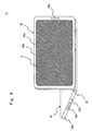
- Fig. 1 is a top-side perspective view schematically showing a mobile terminal device according to this exemplary embodiment.
- Fig. 2 is a bottom-side perspective view schematically showing the mobile terminal device according to this exemplary embodiment.
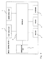
- Fig. 3 is a block diagram of a control system of the mobile terminal device according to the first exemplary embodiment. While a mobile terminal device 1 according to this exemplary embodiment is formed as a mobile telephone, a tablet terminal, a PDA or the like may be used instead of the mobile telephone substantially in a similar way.
- the mobile terminal device 1 includes a housing 2, a first display unit 3, a second display unit 4, a receiver 5, a speaker 6, a microphone 7, a controller 8, and a communication unit 9.
- the housing 2 includes the first display unit 3, the second display unit 4, the receiver 5, the speaker 6, the microphone 7, the controller 8, and the communication unit 9.
- the housing 2 includes surfaces facing each other in the thickness direction, each of the surfaces including an opening.
- the housing 2 according to this exemplary embodiment is formed to have a substantially rectangular shape when seen from the thickness direction.
- the housing 2 includes principal surfaces 2a and 2b facing each other in the thickness direction, side surfaces 2c and 2d facing each other in the longitudinal direction, and side surfaces 2e and 2f facing each other in the transverse direction.
- An opening 2g is formed on a principal surface (first principal surface) 2a of the housing 2.
- an opening 2h is formed on a principal surface (second principal surface) 2b of the housing 2.
- a receiver sound hole 2i is formed in the housing 2.
- the receiver sound hole 2i according to this exemplary embodiment is formed in one side of both sides of the first principal surface 2a facing each other in the longitudinal direction with the opening 2g interposed therebetween. Specifically, the receiver sound hole 2i is formed to penetrate through the first principal surface 2a. Therefore, the receiver sound hole 2i is formed on the same plane as that where the first principal surface 2a is formed.
- the receiver sound hole 2i is arranged substantially at the center of the transverse direction of the housing 2. Further, the receiver sound hole 2i is formed into a long hole and is arranged in such a way that the longitudinal direction of the receiver sound hole 2i is aligned with the transverse direction of the housing 2.
- the shape of the receiver sound hole 2i is not particularly limited.
- a speaker sound hole 2j is formed in the housing 2.
- the speaker sound hole 2j according to this exemplary embodiment is formed on the side surface 2d arranged opposite to the side of the housing 2 in which the receiver sound hole 2i is arranged with the opening 2g interposed therebetween. More specifically, the speaker sound hole 2j is formed to penetrate through the side surface 2d. Accordingly, the speaker sound hole 2j is formed on the same plane as the plane where the side surface 2d is formed.
- the speaker sound hole 2j is arranged substantially at the center of the transverse direction of the housing 2 in the side surface 2d. Further, the speaker sound hole 2j is formed into a long hole and is arranged in such a way that the longitudinal direction of the speaker sound hole 2j is aligned with the transverse direction of the housing 2.
- the shape of the speaker sound hole 2j is not particularly limited.
- a microphone sound hole 2k is formed in the housing 2.
- the microphone sound hole 2k according to this exemplary embodiment is arranged near the speaker sound hole 2j on the side surface 2d and is formed to penetrate through the side surface 2d.
- the arrangement of the microphone sound hole 2k is not particularly limited and it is sufficient if the microphone sound hole 2k is arranged near the user's mouth when the user brings his/her ear close to the receiver sound hole 2i.
- the first display unit 3 serves as an image display unit or an operation unit of the mobile terminal device 1.
- the first display unit 3 is arranged on the side of the first principal surface 2a of the housing 2.
- the first display unit 3 according to this exemplary embodiment includes a backlight, a liquid crystal panel, a touch panel that covers the liquid crystal panel and the like.
- the first display unit 3 is fixed to the housing 2 so that the first display unit 3 is exposed from the opening 2g of the housing 2.
- the second display unit 4 also serves as an image display unit or an operation unit of the mobile terminal device 1.
- the second display unit 4 is arranged on the side of the second principal surface 2b of the housing 2.
- the second display unit 4 is preferably formed in such a manner that the second display unit 4 has substantially the same shape and substantially the same size as those of the first display unit 3.
- the second display unit 4 according to this exemplary embodiment also includes a backlight, a liquid crystal panel, a touch panel that covers the liquid crystal panel and the like.
- the second display unit 4 is fixed to the housing 2 so that the second display unit 4 is exposed from the opening 2h of the housing 2.
- the receiver 5 outputs a received voice or the like.
- the receiver 5 according to this exemplary embodiment is arranged in such a way that the receiver 5 overlap the receiver sound hole 2i in the thickness direction of the housing 2 and is fixed to the housing 2. As a result, the sound output from the receiver 5 is emitted to the outside of the housing 2 from the receiver sound hole 2i.
- the speaker 6 outputs music data or the like stored in a storage unit (not shown).
- the speaker 6 according to this exemplary embodiment is arranged in such a way that the speaker 6 overlap the speaker sound hole 2j in the longitudinal direction of the housing 2 and is fixed to the housing 2. As a result, the sound output from the speaker 6 is emitted to the outside of the housing 2 from the speaker sound hole 2j.
- the microphone 7 converts a user's voice or the like into signals.
- the microphone 7 according to this exemplary embodiment is arranged in such a way that the microphone 7 overlap the microphone sound hole 2k in the longitudinal direction of the housing 2 and is fixed to the housing 2. As a result, the user's voice or the like is input to the microphone 7 through the microphone sound hole 2k.
- the controller 8 achieves a function as the mobile terminal device 1 based on a program stored in a storage unit (not shown). For example, the controller 8 controls the first display unit 3 or the second display unit 4, outputs signals supplied from the communication unit 9 to the receiver 5, or outputs signals supplied from the microphone 7 to the communication unit 9 based on the program stored in the storage unit and input signals from the first display unit 3 or the second display unit 4. Further, the controller 8 outputs music data or the like stored in the storage unit to the speaker 6 based on the program stored in the storage unit and the input signals from the first display unit 3 or the second display unit 4. Further, the controller 8 controls the communication unit 9 based on the program stored in the storage unit and the input signals from the first display unit 3 or the second display unit 4.
- the communication unit 9 demodulates signals transmitted from, for example, a public network to output the demodulated signals to the controller 8 or modulates signals supplied from the controller 8 to output the modulated signals to the public network.
- the mobile terminal device 1 When a user makes a phone call using such a mobile terminal device 1, the user brings his/her ear close to the receiver sound hole 2i and brings his/her mouth close to the microphone sound hole 2k. That is, when the user makes a phone call using the mobile terminal device 1, the mobile terminal device 1 is used in a state in which the longitudinal direction of the housing 2 is aligned with a substantially vertical direction.
- the receiver sound hole 2i is formed in one side of both sides of the first principal surface 2a facing each other in the longitudinal direction with the opening 2g interposed therebetween.
- the speaker sound hole 2j is formed on the side surface 2d arranged opposite to the side of the housing 2 where the receiver sound hole 2i is arranged with the opening 2g interposed therebetween.
- the receiver sound hole 2i and the speaker sound hole 2j are arranged with the opening 2g and the first display unit 3 interposed therebetween. Accordingly, the speaker sound hole 2j can be arranged sufficiently apart from the receiver sound hole 2i.
- the distance between the speaker sound hole 2j and the receiver sound hole 2i corresponds to the length of the longitudinal direction of the housing 2, the distance between them can be sufficiently large. Accordingly, even when a sound is output from the speaker 6 due to an erroneous operation or the like, this sound has little influence on the user since the speaker sound hole 2j is apart from the user's ear.
- the speaker sound hole 2j is formed on the side surface 2d of the housing 2, even when the first principal surface 2a or the second principal surface 2b of the housing 2 comes into contact with the upper surface of a desk or the like when the mobile terminal device 1 is placed on the desk or the like, the speaker sound hole 2j is not obstructed and the sound can be output properly.
- the receiver sound hole 2i and the like are not formed on the side of the second principal surface 2b, it is possible to visually distinguish the first principal surface 2a from the second principal surface 2b of the mobile terminal device 1 easily. Even when such a configuration is employed in which the first display unit 3 and the second display unit 4 are arranged substantially at the same position when the mobile terminal device 1 is rotated about a side of the housing 2, it is possible to distinguish the first principal surface 2a from the second principal surface 2b of the mobile terminal device 1 by checking the surface where the receiver sound hole 2i is formed.
- a mobile terminal device has the same configurations as those of the mobile terminal device according to the first exemplary embodiment except for the arrangement of the speaker. Accordingly, mainly this difference between the above configurations will be described while the overlapping descriptions will be omitted. Elements of these embodiments which are the same are denoted by the same reference symbols.
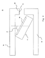
- Fig. 4 is a cross-sectional view showing an area around the speaker of the mobile terminal device according to this exemplary embodiment.
- a speaker 6 of a mobile terminal device 21 is inclined with respect to the side surface 2d of the housing 2.
- a vibrating surface 6a of the speaker 6 is inclined to the side of the first display unit 3 at an angle ⁇ with respect to the side surface 2d of the housing 2 in the state in which the vibrating surface 6a is arranged on the side of the speaker sound hole 2j.
- a mobile terminal device has the same configurations as those of the mobile terminal device according to the first exemplary embodiment except that housings can be opened and closed. Accordingly, mainly this difference between the above configurations will be described while the overlapping descriptions will be omitted. Elements of these embodiments which are the same are denoted by the same reference symbols.
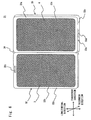
- Fig. 5 is a top-side perspective view showing a state in which housings of the mobile terminal device according to this exemplary embodiment are closed.
- Fig. 6 is a bottom-side perspective view showing a state in which the housings of the mobile terminal device according to this exemplary embodiment are opened.
- a mobile terminal device 31 includes a first housing 32, a second housing 33, and a hinge 34. That is, the first housing 32 and the second housing 33 are coupled via the hinge 34 so that the first housing 32 and the second housing 33 can be opened or closed.
- the first housing 32 is formed to have a substantially rectangular shape when seen from the thickness direction. More specifically, the first housing 32 includes principal surfaces facing each other in the thickness direction, side surfaces facing each other in the longitudinal direction, and side surfaces facing each other in the transverse direction.
- An opening 32b is formed on the principal surface 32a which is in the side opposite to the principal surface in the first housing 32 facing the second housing 33 in the state in which the first housing 32 and the second housing 33 are closed.
- the first display unit 3 is exposed from this opening 32b.
- a receiver sound hole 32c is formed in one side of both sides of the principal surface 32a of the first housing 32 facing each other in the longitudinal direction with the first display unit 3 interposed therebetween.
- the receiver 5 is arranged so that the receiver 5 overlaps the receiver sound hole 32c in the thickness direction of the first housing 32 and is fixed to the first housing 32.
- the second housing 33 is also formed to have a substantially rectangular shape when seen from the thickness direction and formed, for example, to have substantially the same shape and substantially the same size as those of the first housing 32.
- the second housing 33 includes principal surfaces facing each other in the thickness direction, side surfaces facing each other in the longitudinal direction, and side surfaces facing each other in the transverse direction.
- An opening 33b is formed on the principal surface 33a opposite to the principal surface in the second housing 33 facing the first housing 32 in the state in which the first housing 32 and the second housing 33 are closed.
- the second display unit 4 is exposed from this opening 33b.
- the first display unit 3 and the second display unit 4 are exposed in the state in which the first housing 32 and the second housing 33 are closed.
- a speaker sound hole 33d is formed on one of both sides of the second housing 33 facing with each other in the longitudinal direction. More specifically, the speaker sound hole 33d is formed on a side surface 33c arranged opposite to the side of the first housing 32 where the receiver sound hole 32c is arranged with the second display unit 4 interposed therebetween when seen from the thickness direction in the state in which the first housing 32 and the second housing 33 are closed.
- the speaker 6 is arranged so that the speaker 6 overlaps the speaker sound hole 33d in the longitudinal direction of the second housing 33 and is fixed to the second housing 33.
- a microphone sound hole 33e is formed near the speaker sound hole 33d on the side surface 33c of the second housing 33.
- the microphone 7 is arranged so that the microphone 7 overlaps the microphone sound hole 33e in the longitudinal direction of the second housing 33 and is fixed to the second housing 33.
- the speaker sound hole 33d is formed on one of both sides of the second housing 33 facing with each other in the longitudinal direction. More specifically, the speaker sound hole 33d is formed on the side surface 33c arranged opposite to the side of the first housing 32 where the receiver sound hole 32c is arranged with the second display unit 4 interposed therebetween when seen from the thickness direction in the state in which the first housing 32 and the second housing 33 are closed. Accordingly, the speaker sound hole 33d is arranged sufficiently apart from the receiver sound hole 32c in the longitudinal direction of the housing. According to such a configuration, even when a sound is output from the speaker 6 due to an erroneous operation or the like, the sound has little influence on the user since the speaker sound hole 33d is distant from the user's ear.
- the controller 8 and the communication unit 9 may be installed in one of the first housing 32 and the second housing 33.
- the microphone 7 may be installed in the first housing 32 instead of being installed in the second housing 33 and may have a configuration in which a sound is input to the microphone through a microphone sound hole formed in the first housing 32.
- the speaker 6 may be installed in the first housing 32 instead of being installed in the second housing 33 and may have a configuration in which a sound is emitted through a speaker sound hole formed in the first housing 32.
- a display unit may be arranged on the plane in the first housing 32 facing the second housing 33 or on the plane in the second housing 33 facing the first housing 32 when the first housing 32 and the second housing 33 are closed.
- a mobile terminal device has configurations the same as those of the mobile terminal device according to the third exemplary embodiment except for the configuration of the hinge. Accordingly, mainly this difference between the above configurations will be described while the overlapping descriptions will be omitted. Elements of these embodiments which are the same are denoted by the same reference symbols.
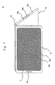
- Fig. 7 is a perspective view schematically showing a state in which a first housing and a second housing of the mobile terminal device according to this exemplary embodiment are opened.
- Fig. 8 is another perspective view schematically showing a state in which the first housing and the second housing of the mobile terminal device according to this exemplary embodiment are opened.
- a hinge 42 of a mobile terminal device 41 is configured to be able to keep the state in which the first housing 32 and the second housing 33 are opened or closed.
- the hinge 42 includes, for example, a stopper function. According to this configuration, as shown in Figs. 7 and 8 , it is possible to fix the angle of the first housing 32 and the second housing 33 to an angle at which a user can easily see the first display unit 3 or the second display unit 4 to place the mobile terminal device 41 on a desk or the like.
- the present invention is applicable to mobile terminal devices such as mobile telephones, tablet terminals, and Personal Digital Assistants (PDAs), and a method for manufacturing the mobile terminal device.
- mobile terminal devices such as mobile telephones, tablet terminals, and Personal Digital Assistants (PDAs)
- PDAs Personal Digital Assistants
Abstract
Description
- The present invention relates to a mobile terminal device and a method for manufacturing the same.
- Mobile telephones, tablet terminals, and Personal Digital Assistants (PDAs) have been widely used as mobile terminal devices, in which much ingenuity has been exercised in the arrangement of receivers, speakers and the like. In a mobile terminal device disclosed in each of
Patent literature -
- Patent literature 1: Japanese Unexamined Patent Application Publication No.
2010-103763 - Patent literature 2: Japanese Unexamined Patent Application Publication No.
2010-68485 - A sound output from the speaker is louder than a sound output from the receiver. It is therefore preferable to arrange the speaker sound hole apart from the receiver sound hole so that a user who brings his/her ear close to the receiver is not influenced by a sound that is output from the speaker due to an erroneous operation or the like.
- However, in the mobile terminal device disclosed in each of
Patent literature - The present invention has been made in order to solve the aforementioned problem and aims to provide a mobile terminal device in which a speaker sound hole is arranged sufficiently apart from a receiver sound hole and a method for manufacturing the mobile terminal device.
- A mobile terminal device according to one exemplary embodiment of the present invention includes: a housing; a first display means that is arranged on a side of a first principal surface in the housing; a second display means that is arranged on a side of a second principal surface opposite to the first principal surface in the housing; a receiver sound hole that is formed on the first principal surface of the housing; a receiver that is fixed in the housing and overlaps the receiver sound hole in a direction perpendicular to the first principal surface of the housing; a speaker sound hole that is formed on a side surface of the housing opposite to the receiver sound hole with the first display means interposed therebetween; and a speaker that is fixed in the housing and overlap the speaker sound hole in a direction perpendicular to a side surface of the housing in which the speaker sound hole is formed.
- A method for manufacturing a mobile terminal device according to one exemplary embodiment of the present invention includes the processes of: arranging a first display means on a side of a first principal surface in a housing; arranging a second display means on a side of a second principal surface opposite to the first principal surface in the housing; forming a receiver sound hole on the first principal surface of the housing; fixing a receiver in the housing so that the receiver overlaps the receiver sound hole in a direction perpendicular to the first principal surface of the housing; forming a speaker sound hole on a side surface of the housing opposite to the receiver sound hole with the first display means interposed therebetween; and fixing a speaker in the housing so that the speaker overlaps the speaker sound hole in a direction perpendicular to a side surface of the housing in which the speaker sound hole is formed.
- According to the present invention, it is possible to provide a mobile terminal device in which a speaker sound hole is arranged sufficiently apart from a receiver sound hole and a method for manufacturing the mobile terminal device.
-
-
Fig. 1 is a top-side perspective view schematically showing a mobile terminal device according to a first exemplary embodiment; -
Fig. 2 is a bottom-side perspective view schematically showing the mobile terminal device according to the first exemplary embodiment; -
Fig. 3 is a block diagram of a control system of the mobile terminal device according to the first exemplary embodiment; -
Fig. 4 is a cross-sectional view showing an area around a speaker of a mobile terminal device according to a second exemplary embodiment; -
Fig. 5 is a top-side perspective view showing a state in which housings of a mobile terminal device according to a third exemplary embodiment are closed; -
Fig. 6 is a bottom-side perspective view showing a state in which the housings of the mobile terminal device according to the third exemplary embodiment are opened; -
Fig. 7 is a perspective view schematically showing a state in which a first housing and a second housing of a mobile terminal device according to a fourth exemplary embodiment are opened; and -
Fig. 8 is another perspective view schematically showing a state in which the first housing and the second housing of the mobile terminal device according to the fourth exemplary embodiment are opened. - A mobile terminal device and a method for manufacturing the mobile terminal device according to exemplary embodiments of the present invention will be described. However, the present invention is not limited to the following exemplary embodiments. For the sake of clarification of the description, the following description and the drawings are simplified as appropriate.
-
Fig. 1 is a top-side perspective view schematically showing a mobile terminal device according to this exemplary embodiment.Fig. 2 is a bottom-side perspective view schematically showing the mobile terminal device according to this exemplary embodiment.Fig. 3 is a block diagram of a control system of the mobile terminal device according to the first exemplary embodiment. While amobile terminal device 1 according to this exemplary embodiment is formed as a mobile telephone, a tablet terminal, a PDA or the like may be used instead of the mobile telephone substantially in a similar way. - As shown in
Figs. 1 to 3 , themobile terminal device 1 includes ahousing 2, afirst display unit 3, asecond display unit 4, areceiver 5, aspeaker 6, amicrophone 7, acontroller 8, and acommunication unit 9. - The
housing 2 includes thefirst display unit 3, thesecond display unit 4, thereceiver 5, thespeaker 6, themicrophone 7, thecontroller 8, and thecommunication unit 9. Thehousing 2 includes surfaces facing each other in the thickness direction, each of the surfaces including an opening. Thehousing 2 according to this exemplary embodiment is formed to have a substantially rectangular shape when seen from the thickness direction. Thehousing 2 includesprincipal surfaces side surfaces side surfaces housing 2. Further, anopening 2h is formed on a principal surface (second principal surface) 2b of thehousing 2. - A
receiver sound hole 2i is formed in thehousing 2. Thereceiver sound hole 2i according to this exemplary embodiment is formed in one side of both sides of the firstprincipal surface 2a facing each other in the longitudinal direction with the opening 2g interposed therebetween. Specifically, thereceiver sound hole 2i is formed to penetrate through the firstprincipal surface 2a. Therefore, thereceiver sound hole 2i is formed on the same plane as that where the firstprincipal surface 2a is formed. Thereceiver sound hole 2i is arranged substantially at the center of the transverse direction of thehousing 2. Further, thereceiver sound hole 2i is formed into a long hole and is arranged in such a way that the longitudinal direction of thereceiver sound hole 2i is aligned with the transverse direction of thehousing 2. However, the shape of thereceiver sound hole 2i is not particularly limited. - Further, a
speaker sound hole 2j is formed in thehousing 2. Thespeaker sound hole 2j according to this exemplary embodiment is formed on theside surface 2d arranged opposite to the side of thehousing 2 in which thereceiver sound hole 2i is arranged with the opening 2g interposed therebetween. More specifically, thespeaker sound hole 2j is formed to penetrate through theside surface 2d. Accordingly, thespeaker sound hole 2j is formed on the same plane as the plane where theside surface 2d is formed. Thespeaker sound hole 2j is arranged substantially at the center of the transverse direction of thehousing 2 in theside surface 2d. Further, thespeaker sound hole 2j is formed into a long hole and is arranged in such a way that the longitudinal direction of thespeaker sound hole 2j is aligned with the transverse direction of thehousing 2. However, the shape of thespeaker sound hole 2j is not particularly limited. - Further, a
microphone sound hole 2k is formed in thehousing 2. Themicrophone sound hole 2k according to this exemplary embodiment is arranged near thespeaker sound hole 2j on theside surface 2d and is formed to penetrate through theside surface 2d. However, the arrangement of themicrophone sound hole 2k is not particularly limited and it is sufficient if themicrophone sound hole 2k is arranged near the user's mouth when the user brings his/her ear close to thereceiver sound hole 2i. - The
first display unit 3 serves as an image display unit or an operation unit of themobile terminal device 1. Thefirst display unit 3 is arranged on the side of the firstprincipal surface 2a of thehousing 2. Thefirst display unit 3 according to this exemplary embodiment includes a backlight, a liquid crystal panel, a touch panel that covers the liquid crystal panel and the like. Thefirst display unit 3 is fixed to thehousing 2 so that thefirst display unit 3 is exposed from the opening 2g of thehousing 2. - The
second display unit 4 also serves as an image display unit or an operation unit of the mobileterminal device 1. Thesecond display unit 4 is arranged on the side of the secondprincipal surface 2b of thehousing 2. Thesecond display unit 4 is preferably formed in such a manner that thesecond display unit 4 has substantially the same shape and substantially the same size as those of thefirst display unit 3. Thesecond display unit 4 according to this exemplary embodiment also includes a backlight, a liquid crystal panel, a touch panel that covers the liquid crystal panel and the like. Thesecond display unit 4 is fixed to thehousing 2 so that thesecond display unit 4 is exposed from theopening 2h of thehousing 2. - The
receiver 5 outputs a received voice or the like. Thereceiver 5 according to this exemplary embodiment is arranged in such a way that thereceiver 5 overlap thereceiver sound hole 2i in the thickness direction of thehousing 2 and is fixed to thehousing 2. As a result, the sound output from thereceiver 5 is emitted to the outside of thehousing 2 from thereceiver sound hole 2i. - The
speaker 6 outputs music data or the like stored in a storage unit (not shown). Thespeaker 6 according to this exemplary embodiment is arranged in such a way that thespeaker 6 overlap thespeaker sound hole 2j in the longitudinal direction of thehousing 2 and is fixed to thehousing 2. As a result, the sound output from thespeaker 6 is emitted to the outside of thehousing 2 from thespeaker sound hole 2j. - The
microphone 7 converts a user's voice or the like into signals. Themicrophone 7 according to this exemplary embodiment is arranged in such a way that themicrophone 7 overlap themicrophone sound hole 2k in the longitudinal direction of thehousing 2 and is fixed to thehousing 2. As a result, the user's voice or the like is input to themicrophone 7 through themicrophone sound hole 2k. - The
controller 8 achieves a function as the mobileterminal device 1 based on a program stored in a storage unit (not shown). For example, thecontroller 8 controls thefirst display unit 3 or thesecond display unit 4, outputs signals supplied from thecommunication unit 9 to thereceiver 5, or outputs signals supplied from themicrophone 7 to thecommunication unit 9 based on the program stored in the storage unit and input signals from thefirst display unit 3 or thesecond display unit 4. Further, thecontroller 8 outputs music data or the like stored in the storage unit to thespeaker 6 based on the program stored in the storage unit and the input signals from thefirst display unit 3 or thesecond display unit 4. Further, thecontroller 8 controls thecommunication unit 9 based on the program stored in the storage unit and the input signals from thefirst display unit 3 or thesecond display unit 4. - The
communication unit 9 demodulates signals transmitted from, for example, a public network to output the demodulated signals to thecontroller 8 or modulates signals supplied from thecontroller 8 to output the modulated signals to the public network. - When a user makes a phone call using such a mobile
terminal device 1, the user brings his/her ear close to thereceiver sound hole 2i and brings his/her mouth close to themicrophone sound hole 2k. That is, when the user makes a phone call using the mobileterminal device 1, the mobileterminal device 1 is used in a state in which the longitudinal direction of thehousing 2 is aligned with a substantially vertical direction. - At this time, in the mobile
terminal device 1 according to this exemplary embodiment, thereceiver sound hole 2i is formed in one side of both sides of the firstprincipal surface 2a facing each other in the longitudinal direction with theopening 2g interposed therebetween. Further, thespeaker sound hole 2j is formed on theside surface 2d arranged opposite to the side of thehousing 2 where thereceiver sound hole 2i is arranged with theopening 2g interposed therebetween. In summary, thereceiver sound hole 2i and thespeaker sound hole 2j are arranged with theopening 2g and thefirst display unit 3 interposed therebetween. Accordingly, thespeaker sound hole 2j can be arranged sufficiently apart from thereceiver sound hole 2i. In particular, since the distance between thespeaker sound hole 2j and thereceiver sound hole 2i corresponds to the length of the longitudinal direction of thehousing 2, the distance between them can be sufficiently large. Accordingly, even when a sound is output from thespeaker 6 due to an erroneous operation or the like, this sound has little influence on the user since thespeaker sound hole 2j is apart from the user's ear. - In addition, since the
speaker sound hole 2j is formed on theside surface 2d of thehousing 2, even when the firstprincipal surface 2a or the secondprincipal surface 2b of thehousing 2 comes into contact with the upper surface of a desk or the like when the mobileterminal device 1 is placed on the desk or the like, thespeaker sound hole 2j is not obstructed and the sound can be output properly. - Further, since the
receiver sound hole 2i and the like are not formed on the side of the secondprincipal surface 2b, it is possible to visually distinguish the firstprincipal surface 2a from the secondprincipal surface 2b of the mobileterminal device 1 easily. Even when such a configuration is employed in which thefirst display unit 3 and thesecond display unit 4 are arranged substantially at the same position when the mobileterminal device 1 is rotated about a side of thehousing 2, it is possible to distinguish the firstprincipal surface 2a from the secondprincipal surface 2b of the mobileterminal device 1 by checking the surface where thereceiver sound hole 2i is formed. In other words, even when such a configuration is employed in which thefirst display unit 3 and thesecond display unit 4 are arranged at the same position in the longitudinal direction and the transverse direction in thehousing 1 when the mobileterminal device 1 is rotated around a side of thehousing 2, it is possible to easily distinguish the firstprincipal surface 2a from the secondprincipal surface 2b of the mobileterminal device 1. - A mobile terminal device according to this exemplary embodiment has the same configurations as those of the mobile terminal device according to the first exemplary embodiment except for the arrangement of the speaker. Accordingly, mainly this difference between the above configurations will be described while the overlapping descriptions will be omitted. Elements of these embodiments which are the same are denoted by the same reference symbols.
-
Fig. 4 is a cross-sectional view showing an area around the speaker of the mobile terminal device according to this exemplary embodiment. As shown inFig. 4 , aspeaker 6 of a mobileterminal device 21 is inclined with respect to theside surface 2d of thehousing 2. Specifically, a vibratingsurface 6a of thespeaker 6 is inclined to the side of thefirst display unit 3 at an angle θ with respect to theside surface 2d of thehousing 2 in the state in which the vibratingsurface 6a is arranged on the side of thespeaker sound hole 2j. According to such a configuration, even when the size of thespeaker 6 is enlarged, the thickness of thehousing 2 can be restrained, which contributes to the improvement of the acoustic characteristics of the mobileterminal device 1 and a reduction in the thickness of the mobile terminal device. - A mobile terminal device according to this exemplary embodiment has the same configurations as those of the mobile terminal device according to the first exemplary embodiment except that housings can be opened and closed. Accordingly, mainly this difference between the above configurations will be described while the overlapping descriptions will be omitted. Elements of these embodiments which are the same are denoted by the same reference symbols.
-
Fig. 5 is a top-side perspective view showing a state in which housings of the mobile terminal device according to this exemplary embodiment are closed.Fig. 6 is a bottom-side perspective view showing a state in which the housings of the mobile terminal device according to this exemplary embodiment are opened. As shown inFigs. 5 and6 , a mobileterminal device 31 includes afirst housing 32, asecond housing 33, and ahinge 34. That is, thefirst housing 32 and thesecond housing 33 are coupled via thehinge 34 so that thefirst housing 32 and thesecond housing 33 can be opened or closed. - The
first housing 32 is formed to have a substantially rectangular shape when seen from the thickness direction. More specifically, thefirst housing 32 includes principal surfaces facing each other in the thickness direction, side surfaces facing each other in the longitudinal direction, and side surfaces facing each other in the transverse direction. - An
opening 32b is formed on theprincipal surface 32a which is in the side opposite to the principal surface in thefirst housing 32 facing thesecond housing 33 in the state in which thefirst housing 32 and thesecond housing 33 are closed. Thefirst display unit 3 is exposed from thisopening 32b. - Further, a
receiver sound hole 32c is formed in one side of both sides of theprincipal surface 32a of thefirst housing 32 facing each other in the longitudinal direction with thefirst display unit 3 interposed therebetween. Thereceiver 5 is arranged so that thereceiver 5 overlaps thereceiver sound hole 32c in the thickness direction of thefirst housing 32 and is fixed to thefirst housing 32. - The
second housing 33 is also formed to have a substantially rectangular shape when seen from the thickness direction and formed, for example, to have substantially the same shape and substantially the same size as those of thefirst housing 32. Specifically, thesecond housing 33 includes principal surfaces facing each other in the thickness direction, side surfaces facing each other in the longitudinal direction, and side surfaces facing each other in the transverse direction. - An
opening 33b is formed on theprincipal surface 33a opposite to the principal surface in thesecond housing 33 facing thefirst housing 32 in the state in which thefirst housing 32 and thesecond housing 33 are closed. Thesecond display unit 4 is exposed from thisopening 33b. In summary, in the mobileterminal device 31, thefirst display unit 3 and thesecond display unit 4 are exposed in the state in which thefirst housing 32 and thesecond housing 33 are closed. - Further, a
speaker sound hole 33d is formed on one of both sides of thesecond housing 33 facing with each other in the longitudinal direction. More specifically, thespeaker sound hole 33d is formed on aside surface 33c arranged opposite to the side of thefirst housing 32 where thereceiver sound hole 32c is arranged with thesecond display unit 4 interposed therebetween when seen from the thickness direction in the state in which thefirst housing 32 and thesecond housing 33 are closed. Thespeaker 6 is arranged so that thespeaker 6 overlaps thespeaker sound hole 33d in the longitudinal direction of thesecond housing 33 and is fixed to thesecond housing 33. - Further, a
microphone sound hole 33e is formed near thespeaker sound hole 33d on theside surface 33c of thesecond housing 33. Themicrophone 7 is arranged so that themicrophone 7 overlaps themicrophone sound hole 33e in the longitudinal direction of thesecond housing 33 and is fixed to thesecond housing 33. - In such a mobile
terminal device 31, thespeaker sound hole 33d is formed on one of both sides of thesecond housing 33 facing with each other in the longitudinal direction. More specifically, thespeaker sound hole 33d is formed on theside surface 33c arranged opposite to the side of thefirst housing 32 where thereceiver sound hole 32c is arranged with thesecond display unit 4 interposed therebetween when seen from the thickness direction in the state in which thefirst housing 32 and thesecond housing 33 are closed. Accordingly, thespeaker sound hole 33d is arranged sufficiently apart from thereceiver sound hole 32c in the longitudinal direction of the housing. According to such a configuration, even when a sound is output from thespeaker 6 due to an erroneous operation or the like, the sound has little influence on the user since thespeaker sound hole 33d is distant from the user's ear. - Note that the
controller 8 and thecommunication unit 9 may be installed in one of thefirst housing 32 and thesecond housing 33. Further, themicrophone 7 may be installed in thefirst housing 32 instead of being installed in thesecond housing 33 and may have a configuration in which a sound is input to the microphone through a microphone sound hole formed in thefirst housing 32. Further, thespeaker 6 may be installed in thefirst housing 32 instead of being installed in thesecond housing 33 and may have a configuration in which a sound is emitted through a speaker sound hole formed in thefirst housing 32. Further, a display unit may be arranged on the plane in thefirst housing 32 facing thesecond housing 33 or on the plane in thesecond housing 33 facing thefirst housing 32 when thefirst housing 32 and thesecond housing 33 are closed. - A mobile terminal device according to this exemplary embodiment has configurations the same as those of the mobile terminal device according to the third exemplary embodiment except for the configuration of the hinge. Accordingly, mainly this difference between the above configurations will be described while the overlapping descriptions will be omitted. Elements of these embodiments which are the same are denoted by the same reference symbols.
-
Fig. 7 is a perspective view schematically showing a state in which a first housing and a second housing of the mobile terminal device according to this exemplary embodiment are opened.Fig. 8 is another perspective view schematically showing a state in which the first housing and the second housing of the mobile terminal device according to this exemplary embodiment are opened. - As shown in
Figs. 7 and8 , ahinge 42 of a mobileterminal device 41 according to this exemplary embodiment is configured to be able to keep the state in which thefirst housing 32 and thesecond housing 33 are opened or closed. Thehinge 42 includes, for example, a stopper function. According to this configuration, as shown inFigs. 7 and8 , it is possible to fix the angle of thefirst housing 32 and thesecond housing 33 to an angle at which a user can easily see thefirst display unit 3 or thesecond display unit 4 to place the mobileterminal device 41 on a desk or the like. - The present invention is not limited to the above exemplary embodiments and may be changed as appropriate without departing from the spirit of the present invention.
- This application is based upon and claims the benefit of priority from Japanese Patent Application No.
2012-238063, filed on October 29, 2012 - The present invention is applicable to mobile terminal devices such as mobile telephones, tablet terminals, and Personal Digital Assistants (PDAs), and a method for manufacturing the mobile terminal device.
-
- 1
- MOBILE TERMINAL DEVICE
- 2
- HOUSING
- 2a
- FIRST PRINCIPAL SURFACE
- 2b
- SECOND PRINCIPAL SURFACE
- 2c, 2d, 2e, 2f
- SIDE SURFACES
- 2g, 2h
- OPENINGS
- 2i
- RECEIVER SOUND HOLE
- 2j
- SPEAKER SOUND HOLE
- 2k
- MICROPHONE SOUND HOLE
- 3
- FIRST DISPLAY UNIT
- 4
- SECOND DISPLAY UNIT
- 5
- RECEIVER
- 6
- SPEAKER
- 6a
- VIBRATING SURFACE
- 7
- MICROPHONE
- 8
- CONTROLLER
- 9
- COMMUNICATION UNIT
- 21
- MOBILE TERMINAL DEVICE
- 31
- MOBILE TERMINAL DEVICE
- 32
- FIRST HOUSING
- 32a
- PRINCIPAL SURFACE
- 32b
- OPENING
- 32c
- RECEIVER SOUND HOLE
- 33
- SECOND HOUSING
- 33a
- PRINCIPAL SURFACE
- 33b
- OPENING
- 33c
- SIDE SURFACE
- 33d
- SPEAKER SOUND HOLE
- 33e
- MICROPHONE SOUND HOLE
- 34
- HINGE
- 41
- MOBILE TERMINAL DEVICE
- 42
- HINGE
Claims (6)
- A mobile terminal device comprising:a housing;a first display means that is arranged on a side of a first principal surface in the housing;a second display means that is arranged on a side of a second principal surface opposite to the first principal surface in the housing;a receiver sound hole that is formed on the first principal surface of the housing;a receiver that is fixed in the housing and overlaps the receiver sound hole in a direction perpendicular to the first principal surface of the housing;a speaker sound hole that is formed on a side surface of the housing opposite to the receiver sound hole with the first display means interposed therebetween; anda speaker that is fixed in the housing and overlaps the speaker sound hole in a direction perpendicular to the side surface of the housing in which the speaker sound hole is formed.
- The mobile terminal device according to Claim 1, wherein the speaker is arranged to be inclined to the side surface of the housing in which the speaker sound hole is formed.
- The mobile terminal device according to Claim 1 or 2, wherein:the housing comprises a first housing, a second housing, and a hinge that couples the first housing and the second housing so that the first housing and the second housing can be opened or closed,the first principal surface in the housing is a surface opposite to a surface in the first housing facing the second housing in a state in which the first housing and the second housing are closed, andthe second principal surface in the housing is a surface opposite to a surface in the second housing facing the first housing in the state in which the first housing and the second housing are closed.
- The mobile terminal device according to Claim 3, wherein the hinge allows the mobile terminal device to keep a state in which the first housing and the second housing are opened or closed.
- The mobile terminal device according to Claim 3 or 4, wherein:the receiver sound hole is formed in the first housing, andthe speaker sound hole is formed in the second housing.
- A method for manufacturing a mobile terminal device, the method comprising the processes of:arranging a first display means on a side of a first principal surface in a housing;arranging a second display means on a side of a second principal surface opposite to the first principal surface in the housing;forming a receiver sound hole on the first principal surface of the housing;fixing a receiver in the housing so that the receiver overlaps the receiver sound hole in a direction perpendicular to the first principal surface of the housing;forming a speaker sound hole on a side surface of the housing opposite to the receiver sound hole with the first display means interposed therebetween; andfixing a speaker in the housing so that the speaker overlaps the speaker sound hole in a direction perpendicular to the side surface of the housing in which the speaker sound hole is formed.
Applications Claiming Priority (2)
| Application Number | Priority Date | Filing Date | Title |
|---|---|---|---|
| JP2012238063 | 2012-10-29 | ||
| PCT/JP2013/003513 WO2014068807A1 (en) | 2012-10-29 | 2013-06-04 | Portable terminal device and meth od for manufacturing portable terminal device |
Publications (3)
| Publication Number | Publication Date |
|---|---|
| EP2913987A1 true EP2913987A1 (en) | 2015-09-02 |
| EP2913987A4 EP2913987A4 (en) | 2016-08-03 |
| EP2913987B1 EP2913987B1 (en) | 2019-04-17 |
Family
ID=50626767
Family Applications (1)
| Application Number | Title | Priority Date | Filing Date |
|---|---|---|---|
| EP13851720.6A Active EP2913987B1 (en) | 2012-10-29 | 2013-06-04 | Mobile terminal device and method for manufacturing the same |
Country Status (5)
| Country | Link |
|---|---|
| US (1) | US9485337B2 (en) |
| EP (1) | EP2913987B1 (en) |
| JP (1) | JPWO2014068807A1 (en) |
| CN (1) | CN104756471A (en) |
| WO (1) | WO2014068807A1 (en) |
Cited By (3)
| Publication number | Priority date | Publication date | Assignee | Title |
|---|---|---|---|---|
| CN108924313A (en) * | 2018-07-27 | 2018-11-30 | 维沃移动通信有限公司 | A kind of electronic equipment and called answering method |
| CN108965522A (en) * | 2018-07-10 | 2018-12-07 | 维沃移动通信有限公司 | A kind of receiver mould group and terminal device |
| WO2020096225A1 (en) | 2018-11-05 | 2020-05-14 | Samsung Electronics Co., Ltd. | Speaker module having inclined diaphragm and electronic device including same |
Families Citing this family (2)
| Publication number | Priority date | Publication date | Assignee | Title |
|---|---|---|---|---|
| CN106162467B (en) * | 2016-08-31 | 2021-12-24 | 歌尔股份有限公司 | Sound pipeline, loudspeaker assembly and two-side sound-emitting mobile phone |
| CN106603775A (en) * | 2016-12-20 | 2017-04-26 | 广东欧珀移动通信有限公司 | Mobile terminal |
Family Cites Families (16)
| Publication number | Priority date | Publication date | Assignee | Title |
|---|---|---|---|---|
| US10728381B2 (en) * | 1999-06-04 | 2020-07-28 | Raman K. Rao | Reconfigurable mobile device interfaces supporting authenticated high quality video, audio, TV and multimedia services |
| CN200947621Y (en) * | 2006-07-28 | 2007-09-12 | 康佳集团股份有限公司 | Bar phone with dual-screen display |
| WO2008015901A1 (en) | 2006-08-03 | 2008-02-07 | Nec Corporation | Portable terminal device and housing for portable terminal device |
| JP2008211736A (en) * | 2007-02-28 | 2008-09-11 | Mitsubishi Electric Corp | Electronic device |
| JP5184018B2 (en) * | 2007-09-14 | 2013-04-17 | 京セラ株式会社 | Electronics |
| US8112130B2 (en) * | 2008-04-01 | 2012-02-07 | Apple Inc. | Receiver acoustic system |
| US8947320B2 (en) | 2008-09-08 | 2015-02-03 | Qualcomm Incorporated | Method for indicating location and direction of a graphical user interface element |
| JP4871932B2 (en) | 2008-09-12 | 2012-02-08 | シャープ株式会社 | Mobile device |
| JP2010103763A (en) | 2008-10-23 | 2010-05-06 | Nec Corp | Portable terminal, and method of mounting portable terminal speaker |
| US8103043B2 (en) * | 2009-02-13 | 2012-01-24 | Kyocera Corporation | Sound-generation arrangements in portable electronic devices |
| JP2011259182A (en) * | 2010-06-08 | 2011-12-22 | Nec Casio Mobile Communications Ltd | Portable terminal device |
| JP5864148B2 (en) | 2010-07-12 | 2016-02-17 | 三菱製鋼株式会社 | Hinge device for electronic equipment |
| WO2012044713A1 (en) * | 2010-10-01 | 2012-04-05 | Imerj LLC | Drag/flick gestures in user interface |
| CN102455739A (en) * | 2010-10-27 | 2012-05-16 | 宏碁股份有限公司 | Electronic device |
| JP5172935B2 (en) | 2010-11-25 | 2013-03-27 | シャープ株式会社 | Foldable mobile terminal |
| JP3167774U (en) * | 2011-01-31 | 2011-05-19 | イワヤ株式会社 | Case for portable device |
-
2013
- 2013-06-04 EP EP13851720.6A patent/EP2913987B1/en active Active
- 2013-06-04 WO PCT/JP2013/003513 patent/WO2014068807A1/en active Application Filing
- 2013-06-04 JP JP2014544211A patent/JPWO2014068807A1/en active Pending
- 2013-06-04 CN CN201380056401.2A patent/CN104756471A/en active Pending
- 2013-06-04 US US14/436,143 patent/US9485337B2/en active Active
Cited By (5)
| Publication number | Priority date | Publication date | Assignee | Title |
|---|---|---|---|---|
| CN108965522A (en) * | 2018-07-10 | 2018-12-07 | 维沃移动通信有限公司 | A kind of receiver mould group and terminal device |
| US11457305B2 (en) | 2018-07-10 | 2022-09-27 | Vivo Mobile Communication Co., Ltd. | Receiver module and terminal device |
| CN108924313A (en) * | 2018-07-27 | 2018-11-30 | 维沃移动通信有限公司 | A kind of electronic equipment and called answering method |
| WO2020096225A1 (en) | 2018-11-05 | 2020-05-14 | Samsung Electronics Co., Ltd. | Speaker module having inclined diaphragm and electronic device including same |
| EP3854110A4 (en) * | 2018-11-05 | 2021-12-15 | Samsung Electronics Co., Ltd. | Speaker module having inclined diaphragm and electronic device including same |
Also Published As
| Publication number | Publication date |
|---|---|
| US20150281412A1 (en) | 2015-10-01 |
| JPWO2014068807A1 (en) | 2016-09-08 |
| EP2913987A4 (en) | 2016-08-03 |
| WO2014068807A1 (en) | 2014-05-08 |
| US9485337B2 (en) | 2016-11-01 |
| EP2913987B1 (en) | 2019-04-17 |
| CN104756471A (en) | 2015-07-01 |
Similar Documents
| Publication | Publication Date | Title |
|---|---|---|
| EP2913987A1 (en) | Portable terminal device and method for manufacturing portable terminal device | |
| WO2019228180A1 (en) | Mobile terminal | |
| WO2010110959A3 (en) | System and method of managing data communication at a portable computing device and a portable computing device docking station | |
| JP6175261B2 (en) | Electronic equipment with microphone | |
| EP1799010A1 (en) | Acoustic apparatus and telephone conversation apparatus | |
| US20090106024A1 (en) | Portable electronic device and a noise suppressing method thereof | |
| CN102802137A (en) | System and method for preventing dropped calls | |
| TW201127083A (en) | Differential microphone unit and portable machine | |
| US20190215615A1 (en) | MEMS microphone | |
| KR20120055168A (en) | Portable terminal with duct for transciever | |
| KR20080010786A (en) | Receiving method during absence of mobile communication terminal using local wireless communication | |
| US20070133820A1 (en) | Channel capacity improvement in wireless mobile communications by voice SNR advancements | |
| US20090170563A1 (en) | Voice communication device | |
| JP2010011079A (en) | Portable electronic device and communication system | |
| US20110153320A1 (en) | Device and method for active noise cancelling and voice communication device including the same | |
| US20120172094A1 (en) | Mobile Communication Apparatus | |
| US10582307B2 (en) | MEMS microphone | |
| KR20120055258A (en) | External noise inflowing apparatus for earphone | |
| EP2866423B1 (en) | Communication device, control method of a communication device, and program | |
| KR20170007114A (en) | Apparatus and method for processing voice signal and terminal | |
| JP2006157199A (en) | Sliding-type portable terminal | |
| KR101672942B1 (en) | A Method for Setting a Function of Improved Auditory Acuity and a Hearing Device Having the Same | |
| KR100454946B1 (en) | Apparatus and control method for intercepting speaker hole before speaking the telephone in mobile communication telephone | |
| JP2012199705A (en) | Communication device and receiving volume setting program | |
| JP2005117117A (en) | Mobile telephone with revolving upper case |
Legal Events
| Date | Code | Title | Description |
|---|---|---|---|
| PUAI | Public reference made under article 153(3) epc to a published international application that has entered the european phase |
Free format text: ORIGINAL CODE: 0009012 |
|
| 17P | Request for examination filed |
Effective date: 20150427 |
|
| AK | Designated contracting states |
Kind code of ref document: A1 Designated state(s): AL AT BE BG CH CY CZ DE DK EE ES FI FR GB GR HR HU IE IS IT LI LT LU LV MC MK MT NL NO PL PT RO RS SE SI SK SM TR |
|
| AX | Request for extension of the european patent |
Extension state: BA ME |
|
| DAX | Request for extension of the european patent (deleted) | ||
| RA4 | Supplementary search report drawn up and despatched (corrected) |
Effective date: 20160705 |
|
| RIC1 | Information provided on ipc code assigned before grant |
Ipc: H04M 1/03 20060101AFI20160630BHEP Ipc: H04M 1/02 20060101ALN20160630BHEP |
|
| STAA | Information on the status of an ep patent application or granted ep patent |
Free format text: STATUS: EXAMINATION IS IN PROGRESS |
|
| 17Q | First examination report despatched |
Effective date: 20180410 |
|
| REG | Reference to a national code |
Ref country code: DE Ref legal event code: R079 Ref document number: 602013054121 Country of ref document: DE Free format text: PREVIOUS MAIN CLASS: H04M0001020000 Ipc: H04M0001030000 |
|
| RIC1 | Information provided on ipc code assigned before grant |
Ipc: H04M 1/03 20060101AFI20180906BHEP Ipc: H04M 1/02 20060101ALN20180906BHEP |
|
| RIC1 | Information provided on ipc code assigned before grant |
Ipc: H04M 1/03 20060101AFI20180907BHEP Ipc: H04M 1/02 20060101ALN20180907BHEP |
|
| GRAP | Despatch of communication of intention to grant a patent |
Free format text: ORIGINAL CODE: EPIDOSNIGR1 |
|
| STAA | Information on the status of an ep patent application or granted ep patent |
Free format text: STATUS: GRANT OF PATENT IS INTENDED |
|
| INTG | Intention to grant announced |
Effective date: 20181024 |
|
| GRAS | Grant fee paid |
Free format text: ORIGINAL CODE: EPIDOSNIGR3 |
|
| GRAA | (expected) grant |
Free format text: ORIGINAL CODE: 0009210 |
|
| STAA | Information on the status of an ep patent application or granted ep patent |
Free format text: STATUS: THE PATENT HAS BEEN GRANTED |
|
| AK | Designated contracting states |
Kind code of ref document: B1 Designated state(s): AL AT BE BG CH CY CZ DE DK EE ES FI FR GB GR HR HU IE IS IT LI LT LU LV MC MK MT NL NO PL PT RO RS SE SI SK SM TR |
|
| REG | Reference to a national code |
Ref country code: GB Ref legal event code: FG4D |
|
| REG | Reference to a national code |
Ref country code: CH Ref legal event code: EP |
|
| REG | Reference to a national code |
Ref country code: DE Ref legal event code: R096 Ref document number: 602013054121 Country of ref document: DE |
|
| REG | Reference to a national code |
Ref country code: AT Ref legal event code: REF Ref document number: 1122802 Country of ref document: AT Kind code of ref document: T Effective date: 20190515 Ref country code: IE Ref legal event code: FG4D |
|
| REG | Reference to a national code |
Ref country code: NL Ref legal event code: MP Effective date: 20190417 |
|
| REG | Reference to a national code |
Ref country code: LT Ref legal event code: MG4D |
|
| PG25 | Lapsed in a contracting state [announced via postgrant information from national office to epo] |
Ref country code: NL Free format text: LAPSE BECAUSE OF FAILURE TO SUBMIT A TRANSLATION OF THE DESCRIPTION OR TO PAY THE FEE WITHIN THE PRESCRIBED TIME-LIMIT Effective date: 20190417 |
|
| PG25 | Lapsed in a contracting state [announced via postgrant information from national office to epo] |
Ref country code: LT Free format text: LAPSE BECAUSE OF FAILURE TO SUBMIT A TRANSLATION OF THE DESCRIPTION OR TO PAY THE FEE WITHIN THE PRESCRIBED TIME-LIMIT Effective date: 20190417 Ref country code: HR Free format text: LAPSE BECAUSE OF FAILURE TO SUBMIT A TRANSLATION OF THE DESCRIPTION OR TO PAY THE FEE WITHIN THE PRESCRIBED TIME-LIMIT Effective date: 20190417 Ref country code: NO Free format text: LAPSE BECAUSE OF FAILURE TO SUBMIT A TRANSLATION OF THE DESCRIPTION OR TO PAY THE FEE WITHIN THE PRESCRIBED TIME-LIMIT Effective date: 20190717 Ref country code: FI Free format text: LAPSE BECAUSE OF FAILURE TO SUBMIT A TRANSLATION OF THE DESCRIPTION OR TO PAY THE FEE WITHIN THE PRESCRIBED TIME-LIMIT Effective date: 20190417 Ref country code: AL Free format text: LAPSE BECAUSE OF FAILURE TO SUBMIT A TRANSLATION OF THE DESCRIPTION OR TO PAY THE FEE WITHIN THE PRESCRIBED TIME-LIMIT Effective date: 20190417 Ref country code: SE Free format text: LAPSE BECAUSE OF FAILURE TO SUBMIT A TRANSLATION OF THE DESCRIPTION OR TO PAY THE FEE WITHIN THE PRESCRIBED TIME-LIMIT Effective date: 20190417 Ref country code: PT Free format text: LAPSE BECAUSE OF FAILURE TO SUBMIT A TRANSLATION OF THE DESCRIPTION OR TO PAY THE FEE WITHIN THE PRESCRIBED TIME-LIMIT Effective date: 20190817 Ref country code: ES Free format text: LAPSE BECAUSE OF FAILURE TO SUBMIT A TRANSLATION OF THE DESCRIPTION OR TO PAY THE FEE WITHIN THE PRESCRIBED TIME-LIMIT Effective date: 20190417 |
|
| PG25 | Lapsed in a contracting state [announced via postgrant information from national office to epo] |
Ref country code: BG Free format text: LAPSE BECAUSE OF FAILURE TO SUBMIT A TRANSLATION OF THE DESCRIPTION OR TO PAY THE FEE WITHIN THE PRESCRIBED TIME-LIMIT Effective date: 20190717 Ref country code: RS Free format text: LAPSE BECAUSE OF FAILURE TO SUBMIT A TRANSLATION OF THE DESCRIPTION OR TO PAY THE FEE WITHIN THE PRESCRIBED TIME-LIMIT Effective date: 20190417 Ref country code: LV Free format text: LAPSE BECAUSE OF FAILURE TO SUBMIT A TRANSLATION OF THE DESCRIPTION OR TO PAY THE FEE WITHIN THE PRESCRIBED TIME-LIMIT Effective date: 20190417 Ref country code: GR Free format text: LAPSE BECAUSE OF FAILURE TO SUBMIT A TRANSLATION OF THE DESCRIPTION OR TO PAY THE FEE WITHIN THE PRESCRIBED TIME-LIMIT Effective date: 20190718 Ref country code: PL Free format text: LAPSE BECAUSE OF FAILURE TO SUBMIT A TRANSLATION OF THE DESCRIPTION OR TO PAY THE FEE WITHIN THE PRESCRIBED TIME-LIMIT Effective date: 20190417 |
|
| REG | Reference to a national code |
Ref country code: AT Ref legal event code: MK05 Ref document number: 1122802 Country of ref document: AT Kind code of ref document: T Effective date: 20190417 |
|
| PG25 | Lapsed in a contracting state [announced via postgrant information from national office to epo] |
Ref country code: IS Free format text: LAPSE BECAUSE OF FAILURE TO SUBMIT A TRANSLATION OF THE DESCRIPTION OR TO PAY THE FEE WITHIN THE PRESCRIBED TIME-LIMIT Effective date: 20190817 |
|
| REG | Reference to a national code |
Ref country code: DE Ref legal event code: R097 Ref document number: 602013054121 Country of ref document: DE |
|
| PG25 | Lapsed in a contracting state [announced via postgrant information from national office to epo] |
Ref country code: EE Free format text: LAPSE BECAUSE OF FAILURE TO SUBMIT A TRANSLATION OF THE DESCRIPTION OR TO PAY THE FEE WITHIN THE PRESCRIBED TIME-LIMIT Effective date: 20190417 Ref country code: SK Free format text: LAPSE BECAUSE OF FAILURE TO SUBMIT A TRANSLATION OF THE DESCRIPTION OR TO PAY THE FEE WITHIN THE PRESCRIBED TIME-LIMIT Effective date: 20190417 Ref country code: AT Free format text: LAPSE BECAUSE OF FAILURE TO SUBMIT A TRANSLATION OF THE DESCRIPTION OR TO PAY THE FEE WITHIN THE PRESCRIBED TIME-LIMIT Effective date: 20190417 Ref country code: DK Free format text: LAPSE BECAUSE OF FAILURE TO SUBMIT A TRANSLATION OF THE DESCRIPTION OR TO PAY THE FEE WITHIN THE PRESCRIBED TIME-LIMIT Effective date: 20190417 Ref country code: MC Free format text: LAPSE BECAUSE OF FAILURE TO SUBMIT A TRANSLATION OF THE DESCRIPTION OR TO PAY THE FEE WITHIN THE PRESCRIBED TIME-LIMIT Effective date: 20190417 Ref country code: RO Free format text: LAPSE BECAUSE OF FAILURE TO SUBMIT A TRANSLATION OF THE DESCRIPTION OR TO PAY THE FEE WITHIN THE PRESCRIBED TIME-LIMIT Effective date: 20190417 Ref country code: CZ Free format text: LAPSE BECAUSE OF FAILURE TO SUBMIT A TRANSLATION OF THE DESCRIPTION OR TO PAY THE FEE WITHIN THE PRESCRIBED TIME-LIMIT Effective date: 20190417 |
|
| REG | Reference to a national code |
Ref country code: CH Ref legal event code: PL |
|
| PLBE | No opposition filed within time limit |
Free format text: ORIGINAL CODE: 0009261 |
|
| STAA | Information on the status of an ep patent application or granted ep patent |
Free format text: STATUS: NO OPPOSITION FILED WITHIN TIME LIMIT |
|
| PG25 | Lapsed in a contracting state [announced via postgrant information from national office to epo] |
Ref country code: SM Free format text: LAPSE BECAUSE OF FAILURE TO SUBMIT A TRANSLATION OF THE DESCRIPTION OR TO PAY THE FEE WITHIN THE PRESCRIBED TIME-LIMIT Effective date: 20190417 Ref country code: IT Free format text: LAPSE BECAUSE OF FAILURE TO SUBMIT A TRANSLATION OF THE DESCRIPTION OR TO PAY THE FEE WITHIN THE PRESCRIBED TIME-LIMIT Effective date: 20190417 |
|
| 26N | No opposition filed |
Effective date: 20200120 |
|
| REG | Reference to a national code |
Ref country code: BE Ref legal event code: MM Effective date: 20190630 |
|
| PG25 | Lapsed in a contracting state [announced via postgrant information from national office to epo] |
Ref country code: TR Free format text: LAPSE BECAUSE OF FAILURE TO SUBMIT A TRANSLATION OF THE DESCRIPTION OR TO PAY THE FEE WITHIN THE PRESCRIBED TIME-LIMIT Effective date: 20190417 |
|
| PG25 | Lapsed in a contracting state [announced via postgrant information from national office to epo] |
Ref country code: IE Free format text: LAPSE BECAUSE OF NON-PAYMENT OF DUE FEES Effective date: 20190604 |
|
| PG25 | Lapsed in a contracting state [announced via postgrant information from national office to epo] |
Ref country code: BE Free format text: LAPSE BECAUSE OF NON-PAYMENT OF DUE FEES Effective date: 20190630 Ref country code: SI Free format text: LAPSE BECAUSE OF FAILURE TO SUBMIT A TRANSLATION OF THE DESCRIPTION OR TO PAY THE FEE WITHIN THE PRESCRIBED TIME-LIMIT Effective date: 20190417 Ref country code: CH Free format text: LAPSE BECAUSE OF NON-PAYMENT OF DUE FEES Effective date: 20190630 Ref country code: LU Free format text: LAPSE BECAUSE OF NON-PAYMENT OF DUE FEES Effective date: 20190604 Ref country code: LI Free format text: LAPSE BECAUSE OF NON-PAYMENT OF DUE FEES Effective date: 20190630 |
|
| PG25 | Lapsed in a contracting state [announced via postgrant information from national office to epo] |
Ref country code: CY Free format text: LAPSE BECAUSE OF FAILURE TO SUBMIT A TRANSLATION OF THE DESCRIPTION OR TO PAY THE FEE WITHIN THE PRESCRIBED TIME-LIMIT Effective date: 20190417 |
|
| PG25 | Lapsed in a contracting state [announced via postgrant information from national office to epo] |
Ref country code: HU Free format text: LAPSE BECAUSE OF FAILURE TO SUBMIT A TRANSLATION OF THE DESCRIPTION OR TO PAY THE FEE WITHIN THE PRESCRIBED TIME-LIMIT; INVALID AB INITIO Effective date: 20130604 Ref country code: MT Free format text: LAPSE BECAUSE OF FAILURE TO SUBMIT A TRANSLATION OF THE DESCRIPTION OR TO PAY THE FEE WITHIN THE PRESCRIBED TIME-LIMIT Effective date: 20190417 |
|
| PG25 | Lapsed in a contracting state [announced via postgrant information from national office to epo] |
Ref country code: MK Free format text: LAPSE BECAUSE OF FAILURE TO SUBMIT A TRANSLATION OF THE DESCRIPTION OR TO PAY THE FEE WITHIN THE PRESCRIBED TIME-LIMIT Effective date: 20190417 |
|
| PGFP | Annual fee paid to national office [announced via postgrant information from national office to epo] |
Ref country code: FR Payment date: 20230628 Year of fee payment: 11 Ref country code: DE Payment date: 20230620 Year of fee payment: 11 |
|
| PGFP | Annual fee paid to national office [announced via postgrant information from national office to epo] |
Ref country code: GB Payment date: 20230622 Year of fee payment: 11 |