EP2913877A1 - Direkt-Alkohol-Brennstoffzelle und Direkt-Alkohol-Brennstoffzellenstapel mit effektiver CO2-Entfernung sowie Verfahren zum Betreiben einer solchen Direkt-Alkohol-Brennstoffzelle - Google Patents
Direkt-Alkohol-Brennstoffzelle und Direkt-Alkohol-Brennstoffzellenstapel mit effektiver CO2-Entfernung sowie Verfahren zum Betreiben einer solchen Direkt-Alkohol-Brennstoffzelle Download PDFInfo
- Publication number
- EP2913877A1 EP2913877A1 EP15000036.2A EP15000036A EP2913877A1 EP 2913877 A1 EP2913877 A1 EP 2913877A1 EP 15000036 A EP15000036 A EP 15000036A EP 2913877 A1 EP2913877 A1 EP 2913877A1
- Authority
- EP
- European Patent Office
- Prior art keywords
- channel
- membrane
- fuel cell
- cathode
- anode
- Prior art date
- Legal status (The legal status is an assumption and is not a legal conclusion. Google has not performed a legal analysis and makes no representation as to the accuracy of the status listed.)
- Granted
Links
Images



Classifications
-
- H—ELECTRICITY
- H01—ELECTRIC ELEMENTS
- H01M—PROCESSES OR MEANS, e.g. BATTERIES, FOR THE DIRECT CONVERSION OF CHEMICAL ENERGY INTO ELECTRICAL ENERGY
- H01M8/00—Fuel cells; Manufacture thereof
- H01M8/10—Fuel cells with solid electrolytes
- H01M8/1009—Fuel cells with solid electrolytes with one of the reactants being liquid, solid or liquid-charged
- H01M8/1011—Direct alcohol fuel cells [DAFC], e.g. direct methanol fuel cells [DMFC]
-
- H—ELECTRICITY
- H01—ELECTRIC ELEMENTS
- H01M—PROCESSES OR MEANS, e.g. BATTERIES, FOR THE DIRECT CONVERSION OF CHEMICAL ENERGY INTO ELECTRICAL ENERGY
- H01M8/00—Fuel cells; Manufacture thereof
- H01M8/10—Fuel cells with solid electrolytes
- H01M8/1009—Fuel cells with solid electrolytes with one of the reactants being liquid, solid or liquid-charged
- H01M8/1011—Direct alcohol fuel cells [DAFC], e.g. direct methanol fuel cells [DMFC]
- H01M8/1013—Other direct alcohol fuel cells [DAFC]
-
- H—ELECTRICITY
- H01—ELECTRIC ELEMENTS
- H01M—PROCESSES OR MEANS, e.g. BATTERIES, FOR THE DIRECT CONVERSION OF CHEMICAL ENERGY INTO ELECTRICAL ENERGY
- H01M8/00—Fuel cells; Manufacture thereof
- H01M8/24—Grouping of fuel cells, e.g. stacking of fuel cells
- H01M8/2455—Grouping of fuel cells, e.g. stacking of fuel cells with liquid, solid or electrolyte-charged reactants
-
- Y—GENERAL TAGGING OF NEW TECHNOLOGICAL DEVELOPMENTS; GENERAL TAGGING OF CROSS-SECTIONAL TECHNOLOGIES SPANNING OVER SEVERAL SECTIONS OF THE IPC; TECHNICAL SUBJECTS COVERED BY FORMER USPC CROSS-REFERENCE ART COLLECTIONS [XRACs] AND DIGESTS
- Y02—TECHNOLOGIES OR APPLICATIONS FOR MITIGATION OR ADAPTATION AGAINST CLIMATE CHANGE
- Y02E—REDUCTION OF GREENHOUSE GAS [GHG] EMISSIONS, RELATED TO ENERGY GENERATION, TRANSMISSION OR DISTRIBUTION
- Y02E60/00—Enabling technologies; Technologies with a potential or indirect contribution to GHG emissions mitigation
- Y02E60/30—Hydrogen technology
- Y02E60/50—Fuel cells
Definitions
- the invention relates to a fuel cell, in particular a direct methanol fuel cell or a direct ethanol fuel cell.
- the invention further relates to a method for operating the aforementioned direct alcohol fuel cell.
- the experimental data was from AA Kulikovsky in "Model of the flow with bubbles in the anode channel and performance of a direct methanol fuel cell", Electrochemistry Communications, Volume 7, Issue 2, February 2005, Pages 237-243 , verified by a model. Thereafter, the formation and growth of the gaseous CO 2 bubbles along the anode channel on the one hand lead to an increase in the flow rate and on the other hand to a significant reduction in the time-averaged local methanol concentration, the second effect significantly reduces the limiting current density of the fuel cell.
- a homogenization of the methanol concentration along the anodic flow channels can be achieved for example by increasing the anodic flow.
- much more fuel is regularly supplied than would be necessary according to the stoichiometry for electrochemical conversion.
- this method does not solve the above-mentioned problem.
- due to the increased supply of fuel even a higher pumping power is regularly required disadvantageously in order to pump the anodic methanol-water mixture through the fuel cell.
- the object of the invention is to provide a new direct alcohol fuel cell, in particular a direct methanol or a direct ethanol fuel cell or a fuel cell stack comprising such single cells, which is the problem of forming at the anode gaseous CO 2 , which regularly forms in the fuel-carrying anode channels dissolves, without the flow of the supplied anodic methanol or ethanol-water mixture is adversely affected.
- the object of the invention is achieved by a direct alcohol fuel cell according to the main claim, as well as by a direct alcohol fuel cell stack according to the independent claim.
- Advantageous embodiments of the fuel cell or of the fuel cell stack can be found in the respectively dependent claims.
- the object of the invention is achieved by a method for operating a fuel cell according to another additional claim.
- the invention relates to a novel direct alcohol fuel cell, which solves on the one hand the problem of gaseous CO 2 -Entstehung and discharge at the anode, without disturbing the flow of fuel-water mixture in the supply channels (channel structures).
- the idea underlying this invention is based on the idea of locally separating the streams of the fuel-water mixture fed in and of the resulting CO2, optionally together with water.
- the fuel ie, for example, a methanol-water mixture or an ethanol-water mixture, although passed through a supply line to the membrane, the actual implementation of the fuel, in which then the CO 2 is formed, but should be done elsewhere.
- the fuel should not be supplied directly but initially via the membrane to the point at which the anodic oxidation takes place.
- the direct alcohol fuel cell according to the invention has an anode, a cathode and an ion-conducting membrane arranged therebetween, which are in the form of an electrode electrolyte unit (MEA).
- MEA electrode electrolyte unit
- the anode and the cathode usually comprise graphite or a metal and take over the function of the current collector.
- the direct alcohol fuel cell according to the invention additionally has at least one fuel channel (FC) (eg a methanol) -WBAermischung), which is provided on the anode side or on the cathode side.
- FC fuel channel
- CO 2 -removal channel CRC
- a channel here means a supply, a discharge or a through-line within an electrode, which is arranged adjacent to the membrane, and through which the liquid resources of a direct alcohol fuel cell are passed, or the resulting gaseous CO 2 can be derived.
- the lines for an oxidant, or for a fuel are thus to be understood rather as passage lines.
- channel is to be understood in particular as a channel structure (recess, groove) which is open on one side in a layer, for example an electrode, and which together with an adjoining further layer, for example a catalyst layer, has a backing layer or the ion-conducting membrane, a closed line for the supply or discharge of a resource or a reaction product is formed.
- a channel structure recess, groove
- each case further layers such as, for example, a flow field, a gas diffusion layer or a bipolar plate may additionally be arranged on the outer sides of the membrane electrode units.
- the membrane electrode assembly typically has a thickness in the range of about 200 microns.
- PEM polymer electrolyte membrane
- As a suitable ion-conducting membrane all the usual electrolytes for the direct alcohol fuel cell can be used.
- the portion of the electrode electrolyte unit (MEA) adjacent to an oxidant (OC) channel comprises a catalyst for reacting the oxidant to form the so-called cathodic catalyst layer (cCl).
- cCl cathodic catalyst layer
- Suitable catalysts for this purpose may be all of the catalysts conventionally used for cathodic oxygen reduction in a direct alcohol fuel cell, for example a Pt catalyst.
- the areas of the regions of the catalyst layers are at least so large that they completely cover the channels for the electrode electrolyte unit (MEA).
- the areas can also be chosen larger.
- the anodic or cathodic catalyst in the production of the fuel cell, is applied directly to one side of the membrane, so that it is almost completely on the surface of the membrane.
- the region of the electrode electrolyte unit (MEA) which directly or via a backing layer adjoins a channel for the fuel (FC) has no catalyst according to the invention.
- the direct alcohol fuel cell according to the invention has at least one additional channel (CrC) on the anode side compared to the previously known fuel cells, which is provided specifically for the removal of the CO 2 formed by the anodic oxidation of the alcohol.
- the supply of the alcohol as fuel in particular in the form of a liquid methanol or ethanol-water mixture, takes place through the channels for the fuel (FC).
- the direct alcohol fuel cell are possible in which the one or more channels for supplying the fuel (FC) are arranged either on the anode side or on the cathode side.
- the fuel cell according to the invention is suitable for the use of short-chain alcohols, in particular for the use of methanol or ethanol as a fuel.
- a sufficiently large distance in the sense of the invention means a distance of at least 1 mm.
- the channels for supplying the fuel are arranged on the surface of the electrodes individually and clearly separated from the channels for supplying the oxidant.
- this distance is undershot and is of the order of the membrane layer thickness
- at least one additional separating device is arranged and indeed such from an anodic catalyst layer to the counter electrode, i. H. the cathode is enough.
- this separation device is arranged such that a membrane region which borders on a channel for a fuel (FC) is separated from a membrane region which borders on an oxidant (OC) channel. This separator thus prevents periodically that the alcohol from a channel for a fuel can permeate through the membrane directly to the cathodic catalyst layer.
- any material can be used which is not electronically conductive and not designed to be conductive ions. In addition, it should not undergo chemical reactions with the membrane material, with the alcohol or the catalyst layers, and be stable at temperatures at which the direct alcohol fuel cell (DMFC) is typically operated, eg, up to about 200 ° C.
- DMFC direct alcohol fuel cell
- a plastic in particular Teflon, could be used.
- the separating device is advantageously arranged perpendicular to the cell plane.
- the distance between the channels does not matter.
- a separator is not mandatory in that respect.
- the inventive method for operating a direct alcohol fuel cell provides that the fuel cell both fuel and an oxidizing agent, preferably air, is supplied via in each case at least one channel, and the CO 2 formed , via a separate, from the channel for the fuel-separated channel, optionally together with water, can be deducted.
- an oxidizing agent preferably air
- the channel for discharging the CO 2 formed on the anode side can advantageously also be actively rinsed in a further embodiment with a gaseous or liquid medium, for example water, in order to support the removal of the CO 2 .
- a gaseous or liquid medium for example water
- the fuel cell according to the invention is a direct alcohol fuel cell, for the sake of simplicity, a direct methanol fuel cell (DMFC) will be described below as a specific embodiment of the invention, without thereby limiting the invention.
- DMFC direct methanol fuel cell
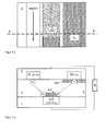
- the channel for supplying the fuel (FC) on the cathode side 3 is arranged.
- the Figures 1b and 1d show such a configuration schematically in cross section and the FIGS. 1 a and 1 c each considered such an embodiment from above.
- the ion-conducting membrane 3 is arranged between the anode 1 and the cathode 2.
- a supply channel for an oxidizing agent (OC) for example air
- a feed channel for a fuel (FC) for example, a methanol-water mixture
- the anode 1 also has an outlet channel (CrC) adjacent to the membrane, which is provided for the discharge of the CO 2 .
- each with a backing layer 6 between the electrodes 1, 2 and the catalyst layer (ccl or acl) adjacent to the membrane 3 or a layer (5) not having a catalyst is shown in FIG FIG. 5 shown.
- the channel for supplying or passing through the methanol-water mixture (FC) and the anode (1) on opposite sides of the membrane (3) is arranged.
- both the oxidant and the fuel are supplied from the cathode side to the direct methanol fuel cell.
- FIG. 1b While in FIG. 1b an embodiment of the fuel cell according to the invention is shown in which the channel for supplying the fuel (FC) and the channel for supplying the oxidant (OC) has a sufficiently large distance, is in Figure 1d a further embodiment of the fuel cell according to the invention shown, which additionally has a separator 4.
- the separator 4 extends between the two channels for supplying the fuel (FC) and the oxidant (OC) and separates them from each other.
- the fuel freely permeates through the membrane to the anodic catalyst layer where it is oxidized, migrating in the region of the membrane the channel adjacent to the supply of the oxidizing agent, the protons generated in the oxidation of alcohol to the cathodic catalyst layer and are reduced there to water.
- the methanol, or the methanol-water mixture through the channel for the fuel (FC) on the cathode side (3) of the fuel cell is provided.
- the supplied methanol diffuses through the polymer electrolyte membrane (3), typically Nafion ®, the catalyst layer on the anode side (ACL).
- the methanol is converted into protons and electrons by the methanol oxidation reaction.
- the methanol crossover through the membrane (3) is regularly large enough to transport sufficient methanol to the anode 1, and to the anodic catalyst layer (acl). A transport limitation is thus regularly excluded during operation of the fuel cell.
- the membrane 3 can be made correspondingly thin in order to still catch any obstructions that may occur due to the methanol cross-over .
- the layer thickness of the anodic catalyst layer (acl) can advantageously be increased slightly compared to conventional layer thicknesses.
- the layer thicknesses of conventional catalyst layers are approximately 100 ⁇ m. Since in the present invention, the methanol access to the anodic catalyst layer (acl) - unlike usual - not over the entire surface of the adjacently arranged feed channel, but according to the invention first through the membrane and then especially over one side of the catalyst layer, the access of the methanol can advantageously be improved if either the area of the area of the anodic catalyst layer (acl) as a whole and / or the layer thickness of this layer itself are increased.
- the suitable layer thicknesses of the anodic catalyst layer are in the usual range, ie between 10 and 100 ⁇ m.
- the suitable layer thicknesses of the anodic catalyst layer are somewhat higher, that is to say in the range between 50 and 300 ⁇ m, advantageously in the range around 200 ⁇ m.
- the protons formed in the oxidation of the methanol on the anode side migrate through the membrane (3) to the cathode side 2, preferably to where a cathodic catalyst can assist the cathodic oxygen reduction reaction, i. H. to the cathodic catalyst layer (ccl) adjacent to the channel for an oxidant (OC).
- the cathodic catalyst layer (ccl) can advantageously reach as far as the separating device 4, but this is not absolutely necessary.
- FIG. 1 a and 1 c show the embodiments according to the Figures 1b and 1d each viewed from above.
- the catalyst layers are each hatched.
- the cutting plane AB in the FIGS. 1a and 1c would then, for example, to cross sections according to the Figures 1b and 1d to lead.
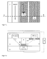
- the DMFC now has the channel for supplying the fuel (FC) on the anode side.
- This embodiment is schematically in the cross sections according to the FIGS. 2b and 2d shown.
- the difference between the FIGS. 2b (2a ) and 2d (2c) can be seen in the optional separation unit 4, analogous to the embodiments according to the FIGS. 1a to 1 d.
- the methanol supplied on the anode side can migrate directly through the membrane to the adjacent anodic catalyst layer (acl) due to the methanol cross-over , where it is then oxidized, and the resulting CO 2 through the channel adjacent to the catalyst layer be passed to the CO 2 exhaust from the fuel cell.
- acl anodic catalyst layer
- the arrangement of the channel for supplying the fuel (FC) takes place on the anode side in a particular embodiment such that in this case the membrane area adjacent to the channel for a fuel (FC), of the membrane area, which is connected to a channel for a Oxidant (OC) borders, is separated by a separator 4. ( Figures 2c, 2d ). This separator periodically prevents methanol from permeating the channel for fuel through the membrane directly to the cathodic catalyst layer.
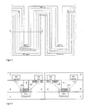
- the supply and discharge channels for the fuel (FC) or the oxidizing agent (OC) are arranged, for example, non-linearly but in the form of a meander over the membrane 3 (see FIG. 3 ).
- separating device 4 it must be ensured in an optionally present separating device 4 that the membrane region which borders on the fuel channel and the membrane region which adjoins the oxidant channel have no direct contact with one another, but only via the separating device 4 and an anodic catalyst layer (acl ) are arranged adjacent.
- this also determines the shape of the CO 2 laxative channel (CrC), since this is adapted via the anodic catalyst layer (acl) in the course of the separator 4.
- the CO 2 laxative channel (CrC) is shown here by dashed lines. For clarity, the catalyst layers adjacent to the channels (acl and ccl) were not shown here, as was the interconnection as a fuel cell.
- FIG. 4 is again a schematic cross section through part of a direct methanol fuel cell according to the invention according to the section AB FIG. 3 shown.
- the cathodic catalyst layer (ccl) extends over the entire area between the respective separation devices 4.
- this is only a special design and not mandatory. It is only important that the leading to the oxidant channels (OC) adjacent areas of the membrane 3 are completely covered by the catalyst layer (ccl).
- the core idea of the present invention is, on the one hand, a feed channel for a fuel, which has no catalyst in the region of the membrane, and thus only permits transport of the alcohol into the membrane, and, on the other hand, an additional, further channel on the anode side of the fuel cell which adjoins is arranged to an anodic catalyst through which only the formed by the anodic oxidation of the alcohol at the anode, gaseous CO 2 can be advantageously dissipated.
- the channel can be advantageously filled or rinsed with water or an inert gas.
- the carbon dioxide generated at the anode would become Form CO 2 gas bubbles leaving the channel, and thus advantageously prevent reverse oxygen can penetrate into the channel.
- FIG. 5 shows by way of example yet another particular embodiment of the invention, in which between the membrane 3 with the adjoining layers with catalyst (acl, ccl) and without catalyst 5 and the two electrodes 1, 2 each have a separate backing layer 6, for example made of porous carbon paper or fabric.
Landscapes
- Life Sciences & Earth Sciences (AREA)
- Engineering & Computer Science (AREA)
- Manufacturing & Machinery (AREA)
- Sustainable Development (AREA)
- Sustainable Energy (AREA)
- Chemical & Material Sciences (AREA)
- Chemical Kinetics & Catalysis (AREA)
- Electrochemistry (AREA)
- General Chemical & Material Sciences (AREA)
- Fuel Cell (AREA)
Abstract
Description
- Die Erfindung betrifft eine Brennstoffzelle, insbesondere eine Direkt-Methanol-Brennstoffzelle oder eine Direkt-Ethanol-Brennstoffzelle. Die Erfindung betrifft ferner ein Verfahren zum Betreiben der vorgenannten Direkt-Alkohol-Brennstoffzelle.
- Als eines der größten Probleme bei der Direkt-Methanol-Brennstoffzellen (DMFC) - Technologie hat sich neben der schlechten Kinetik der Methanoloxidation und des Methanol Cross-Overs durch die Membran zudem die Bildung von gasförmigem CO2 an der Anode der Brennstoffzelle herausgestellt. Bei einer Direkt-Methanol-Brennstoffzelle wird flüssiges Methanol bzw. eine Methanol-Wassermischung als Brennstoff zur anodischen Katalysatorschicht geführt und dort oxidiert. Als Produkt der Methanol-Oxidationsreaktion (engl.: methanol oxidation reaction = MOR) entsteht CO2, welches nun seinerseits wieder zurück in die Anodenkanäle permeiert und dort auf Grund der geringen Löslichkeit in Form von gasförmigen CO2-Blasen regelmäßig zu einer Störung des Durchflusses des Methanols, bzw. der Methanol-Wassermischung führt. Insbesondere bei mäanderförmigen und langen Methanolzuführungskanälen sinkt die Methanol-Konzentration auf Grund der ständig neu gebildeten CO2-Blasen zum Kanalende hin erheblich ab. Dies konnte auch in praktischen Untersuchungen von H. Yang, T.S. Zhao und Q.Ye in "Pressure drop behavior in the anode flow field of liquid feed direct methanol fuel cells", Journal of Power Sources, Volume 142, Issues 1-2, 24 March 2005, Pages 117-124, belegt werden. Es hat sich gezeigt, dass der Druckabfall über die Anode bei einer senkrecht angeordneten, serpentinenartigen Kanalstruktur zunächst bei insgesamt geringen Stromdichten mit steigender Stromdichte ansteigt, um anschließend bei höheren Stromdichten wieder deutlich abzufallen. Gleichzeitig steigt der Druckabfall mit steigender Durchflussrate der eingesetzten Methanol-Wassermischung. Es konnte zudem gezeigt werden, dass die Betriebstemperatur der Zelle und die eingesetzte Methanol-Konzentration einen deutlichen Einfluss auf die Zellleistung, nicht jedoch auf den Druckabfall haben.
- Bereits bei moderaten Stromstärken steigt die Geschwindigkeit des Anodendurchflusses am Anodenauslass auf Grund der gebildeten CO2-Blasen drastisch, das heißt in der Regel um mehr als eine Größenordnung, an. Dieser Anstieg in der Strömungsgeschwindigkeit wird begleitet von einer starken Verringerung der Methanol-Konzentration nahe am Anodenauslass. Dies führt wiederum zu einem Anstieg in der anodischen Überspannung, welche einerseits das Zellpotential reduziert aber andererseits nachteilig die Korrosionsrate von Kohlenstoff und Ruthenium in der anodischen Katalysatorschicht erhöht.
- Die experimentellen Daten wurden von A.A. Kulikovsky in "Model of the flow with bubbles in the anode channel and performance of a direct methanol fuel cell", Electrochemistry Communications, Volume 7, Issue 2, February 2005, Pages 237-243, durch ein Modell verifiziert. Danach führen die Entstehung und das Anwachsen der gasförmigen CO2-Blasen entlang des Anodenkanals einerseits zu einer Erhöhung der Durchflussrate und andererseits zu einer deutlichen Verringerung der zeitlich gemittelten lokalen Methanol-Konzentration, wobei der zweite Effekt die begrenzende Stromdichte der Brennstoffzelle deutlich herabsenkt.
- Um eine Direkt-Methanol-Brennstoffzelle in einem optimalen Bereich zu betreiben, ist daher neben der Temperatur und der Methanol-Konzentration insbesondere eine Optimierung des Flowfields auf der Anodenseite anzustreben, um das Ausmaß an gebildeten CO2-Blasen innerhalb des zugeführten Brennstoffs zu reduzieren.
- In der Regel kann eine Homogenisierung der Methanol-Konzentration entlang der anodischen Durchflusskanäle beispielsweise durch eine Erhöhung des anodischen Durchflusses erzielt werden. Dadurch wird regelmäßig viel mehr Brennstoff zugeführt, als es nach der Stöchiometrie zur elektrochemischen Umsetzung notwendig wäre. Bei dieser Methode wird jedoch nicht das vorab angesprochene Problem gelöst. Im Gegenteil, durch die erhöhte Zufuhr von Brennstoff wird regelmäßig sogar nachteilig eine höhere Pumpleistung benötigt, um die anodische Methanol-Wassermischung durch die Brennstoffzelle zu pumpen.
- Aufgabe der Erfindung ist es, eine neue Direkt-Alkohol-Brennstoffzelle, insbesondere eine Direkt-Methanol- oder eine Direkt-Ethanol Brennstoffzelle oder einen Brennstoffzellenstapel umfassend derartige Einzelzellen bereit zustellen, die das Problem des sich an der Anode bildenden gasförmigen CO2, welches sich regelmäßig in den den Brennstoff führenden Anodenkanälen ausbildet, löst, ohne dass dazu der Durchfluss der zugeführten anodischen Methanol- bzw. Ethanol-Wassermischung nachteilig gestört wird.
- Die Aufgabe der Erfindung wird gelöst durch eine Direkt-Alkohol-Brennstoffzelle gemäß Hauptanspruch, sowie durch einen Direkt-Alkohol-Brennstoffzellenstapel gemäß Nebenanspruch. Vorteilhafte Ausgestaltungen der Brennstoffzelle bzw. des Brennstoffzellenstapels finden sich in den jeweils darauf rückbezogenen Ansprüchen wieder. Ferner wird die Aufgabe der Erfindung gelöst durch ein Verfahren zum Betreiben einer Brennstoffzelle gemäß weiterem Nebenanspruch.
- Gegenstand der Erfindung ist eine neuartige Direkt-Alkohol-Brennstoffzelle, die einerseits das Problem der gasförmigen CO2-Entstehung und Ableitung an der Anode löst, ohne dabei den Durchfluss der Brennstoff-Wassermischung in den Zuführungskanälen (Kanalstrukturen) zu stören. Die dieser Erfindung zu Grunde liegende Idee basiert auf der Vorstellung, die Ströme der zugeführten Brennstoff-Wassermischung und des entstehenden CO2s, ggfs. zusammen mit Wasser, lokal voneinander zu trennen. Dazu soll der Brennstoff, d. h. beispielsweise eine Methanol-Wassermischung oder eine Ethanol-Wassermischung, zwar über eine Zuführungsleitung bis zur Membran geleitet werden, die eigentliche Umsetzung des Brennstoffs, bei der dann das CO2 gebildet wird, soll aber an anderer Stelle erfolgen. Insbesondere soll der Brennstoff nicht direkt sondern zunächst über die Membran der Stelle zugeführt werden, an der die anodische Oxidation stattfindet.
- Dazu weist die erfindungsgemäße Direkt-Alkohol-Brennstoffzelle eine Anode, einer Kathode sowie einer dazwischen angeordnete Ionen leitenden Membran auf, die in Form einer Elektroden-Elektrolyteinheit (engl. membrane electrode assembly = MEA) vorliegen.
- Die Anode und die Kathode umfassen in der Regel Graphit oder ein Metall und übernehmen die Funktion der Stromsammler.
- Darüber hinaus weist die erfindungsgemäße Direkt-Alkohol-Brennstoffzelle neben wenigstens einem Kanal für ein Oxidationsmittel (engl. oxidant channel = OC) auf der Kathodenseite zusätzlich wenigstens einem Kanal für einen Brennstoff (engl. fuel channel = FC) (z. B. eine Methanol-Wassermischung) auf, der auf der Anodenseite oder auf der Kathodenseite vorgesehen ist.
- Ferner sieht die erfindungsgemäße Direkt-Alkohol-Brennstoffzelle wenigstens einen weiteren Kanal vor, der speziell zur Ableitung des gebildeten gasförmigen CO2 (engl. CO2-removal channel = CRC), gegebenenfalls auch zusammen mit Wasser, auf der Anodenseite angeordnet ist.
- Im Rahmen der Erfindung wird hier unter einem Kanal eine Zuführungs-, eine Abführungs- bzw. eine Durchgangsleitung innerhalb einer Elektrode verstanden, die benachbart zur Membran angeordnet ist, und durch die die flüssigen Betriebsmittel einer Direkt-Alkohol-Brennstoffzelle geleitet, bzw. das entstandene gasförmige CO2 abgeleitet werden können. Insbesondere bei einer anodischen oder kathodischen Kreislaufführung sind die Leitungen für ein Oxidationsmittel, bzw. für einen Brennstoff somit eher als Durchgangsleitungen aufzufassen.
- Im Rahmen der Erfindung ist unter dem Begriff Kanal insbesondere eine Kanalstruktur (Aussparung, Nut) zu verstehen, die einseitig offen in einer Schicht, beispielsweise einer Elektrode, vorhanden ist, und die zusammen mit einer daran angrenzenden weiteren Schicht, beispielsweise einer Katalysatorschicht, einer backing layer oder der Ionen leitenden Membran, eine geschlossene Leitung zur Zu- oder Abführung eines Betriebsmittels oder eines Reaktionsproduktes ausbildet.
- In einer Ausgestaltung der Erfindung können jeweils an den äußeren Seiten der Membran-Elektrodeneinheiten zusätzlich noch weitere Schichten wie beispielsweise ein Strömungsfeld (flowfiled), eine Gasdiffusionsschicht oder eine Bipolarplatte angeordnet sein. Die Membran-Elektrodeneinheit weist typischerweise eine Dicke im Bereich von ca. 200 µm auf.
- Die Membran selbst umfasst in der Regel ein Polymer (engl. polymer electrolyte membrane = PEM), ist Ionen leitend, insbesondere Protonen leitend, und blockiert den Transport von Elektronen. Als geeignete Ionen leitende Membran können alle bislang für die Direkt-Alkohol-Brennstoffzelle üblichen Elektrolyte eingesetzt werden.
- Der Bereich der Elektroden-Elektrolyteinheit (MEA), der an einen Kanal für ein Oxidationsmittel (OC) angrenzt, umfasst einen Katalysator zur Umsetzung des Oxidationsmittels und bildet die sogenannte kathodische Katalysatorschicht (engl. cathode catalyst layer = ccl). Als dafür geeignete Katalysatoren können alle bislang für die anodische Oxidation in einer Direkt-Alkohol-Brennstoffzelle üblichen Katalysatoren eingesetzt werden, beispielsweise ein Pt-Ru-Katalysator.
- Der Bereich der Elektroden-Elektrolyteinheit (MEA), der direkt oder über eine backing layer an den Kanal für die Ableitung des gebildeten CO2 (CRC) angrenzt, umfasst einen Katalysator zur Umsetzung des Brennstoffs und bildet die sogenannte anodische Katalysatorschicht (engl. anode catalyst layer = acl). Als dafür geeignete Katalysatoren können alle bislang für die kathodische Sauerstoffreduktion in einer Direkt-Alkohol-Brennstoffzelle üblichen Katalysatoren eingesetzt werden, beispielsweise ein Pt-Katalysator.
- Die Flächen der Bereiche der Katalysatorschichten sind dabei erfindungsgemäß wenigstens so groß, dass sie die Kanäle zur Elektroden-Elektrolyteinheit (MEA) hin jeweils vollständig abdecken. Darüber hinaus können die Flächen aber auch größer gewählt werden.
- In einer Ausgestaltung der Erfindung wird bei der Herstellung der Brennstoffzelle der anodische oder kathodische Katalysator direkt auf eine Seite der Membran aufgebracht, so dass er sich nahezu vollständig auf der Oberfläche der Membran befindet.
- In einer weiteren Ausgestaltung der Erfindung kann der entsprechende anodische oder kathodische Katalysator bei der Herstellung der Brennstoffzelle zunächst auf einem sehr dünnen porösen Kohlenstoffpapier oder einem Kohlenstoffgewebe (backing layer) aufgebracht, und dieses im Anschluss zwischen Membran und der jeweiligen Elektrode verpresst werden.
- Der Bereich der Elektroden-Elektrolyteinheit (MEA), der direkt oder über eine backing layer an einen Kanal für den Brennstoff (FC) angrenzt, weist demgegenüber erfindungsgemäß keinen Katalysator auf.
- Die erfindungsgemäße Direkt-Alkohol-Brennstoffzelle weist gegenüber den bislang bekannten Brennstoffzellen mindestens einen zusätzlichen Kanal (CrC) auf der Anodenseite auf, der eigens für die Abführung des durch die anodische Oxidation des Alkohols gebildeten CO2 vorgesehen ist. Davon lokal getrennt findet die Zuführung des Alkohols als Brennstoff, insbesondere in Form einer flüssigen Methanol- oder Ethanol-Wassermischung, durch die Kanäle für den Brennstoff (FC) statt. Dabei sind Ausgestaltungen der Direkt-Alkohol-Brennstoffzelle möglich, bei denen der oder die Kanäle zur Zuführung des Brennstoffs (FC) entweder auf der Anodenseite oder auf der Kathodenseite angeordnet sind.
- Die erfindungsgemäße Brennstoffzelle ist für den Einsatz von kurzkettigen Alkoholen, insbesondere für den Einsatz von Methanol oder Ethanol als Brennstoff geeignet.
- Es hat sich herausgestellt, dass unter der Voraussetzung, dass zwischen dem Kanal zur Zuführung des Brennstoffs und dem Kanal zur Zuführung des Oxidationsmittels, sofern sie beide auf der Kathodenseite angeordnet sind, ein ausreichend großer Abstand gegeben ist, der Stofftransport des Alkohols vom Brennstoffkanal durch die Membran zur Kathode, bzw. zu der Kathodenkatalysatorschicht im Unterschied zum Transport des Alkohols zur Anodenkatalysatorschicht regelmäßig sehr gering ausfällt. Unter einem ausreichend großen Abstand im Sinne der Erfindung wird ein Abstand von wenigstens 1 mm verstanden.
- Die Kanäle zur Zuführung des Brennstoffs sind dabei auf der Oberfläche der Elektroden einzeln und klar abgetrennt von den Kanälen zur Zuführung des Oxidationsmittels angeordnet.
- Für eine Ausgestaltung der erfindungsgemäßen Brennstoffzelle, bei der dieser Abstand unterschritten wird und in der Größenordnung der Membranschichtdicke liegt, sieht eine vorteilhafte Ausgestaltung der Erfindung vor, dass innerhalb der zwischen der Anode und der Kathode angeordneten Membran wenigstens eine zusätzliche Trennvorrichtung angeordnet ist und zwar derart, dass sie von einer anodischen Katalysatorschicht bis zur Gegenelektrode, d. h. der Kathode reicht. Ferner ist diese Trennvorrichtung derart angeordnet, dass ein Membranbereich, der an einen Kanal für einen Brennstoffs (FC) grenzt, von einem Membranbereich, der an einen Kanal für ein Oxidationsmittel (OC) grenzt, abtrennt ist. Diese Trennvorrichtung verhindert somit regelmäßig, dass der Alkohl aus einem Kanal für einen Brennstoff durch die Membran direkt zur kathodischen Katalysatorschicht permeieren kann.
- Als Material für diese Trennvorrichtung kann jedes Material verwendet werden, welches nicht Elektronen leitend und nicht Ionen leitend ausgestaltet ist. Es sollte zudem keine chemischen Reaktionen mit dem Membranmaterial, mit dem Alkohol oder den Katalysatorschichten eingehen und bei Temperaturen stabil sein, bei denen die Direkt-Alkohol-Brennstoffzelle (DMFC) typischerweise betrieben wird, also beispielsweise bis ca. 200 °C.
- Als geeignetes Material für diese Trennvorrichtung könnte beispielsweise ein Kunststoff, insbesondere Teflon, eingesetzt werden.
- Die Trennvorrichtung ist vorteilhaft senkrecht zu der Zellebene angeordnet.
- Für die Ausgestaltung der Erfindung, bei der der Kanal zur Zuführung des Brennstoffs und der Kanal zur Zuführung des Oxidationsmittels jeweils auf unterschiedlichen Elektroden angeordnet sind, spielt der Abstand zwischen den Kanälen demgegenüber keine Rolle. Eine Trennvorrichtung ist insofern nicht zwingend notwendig.
- Das erfindungsgemäße Verfahren zum Betreiben einer erfindungsgemäßen Direkt-Alkohol-Brennstoffzelle sieht vor, dass der Brennstoffzelle sowohl Brennstoff als auch ein Oxidationsmittel, bevorzugt Luft, über jeweils wenigstens einen Kanal zugeführt wird, und das gebildete CO2, über eine separate, von dem Kanal für den Brennstoff getrennten Kanal, gegebenenfalls zusammen mit Wasser, abgezogen werden kann.
- Dabei kann der Kanal zur Abführung des anodenseitig gebildeten CO2 in einer weiteren Ausführungsform vorteilhaft zusätzlich mit einem gasförmigen oder flüssigen Medium, beispielsweise Wasser, zur Unterstützung des Abtransportes des CO2 auch aktiv gespült werden.
- Nachfolgend wird die Erfindung anhand einiger Figuren näher erläutert. Obwohl die erfindungsgemäße Brennstoffzelle eine Direkt-Alkohol-Brennstoffzelle ist, wird im Folgenden der Einfachheit halber eine Direkt-Methanol-Brennstoffzelle (DMFC) als besondere Ausführungsform der Erfindung näher beschrieben, ohne dass dadurch eine Einschränkung der Erfindung erfolgt.
- Alle Ausgestaltungen und Wirkungsweisen gelten in gleicher Weise auch für Brennstoffzellen, die mit allen übrigen kurzkettigen Alkoholen, insbesondere auch mit Ethanol als Brennstoff betrieben werden können. In der Figuren bedeuten jeweils:
- 1
- Anode
- 2
- Kathode
- 3
- Elektrolyt (Polymerelektrolyt)
- 4
- Trennvorrichtung (optional)
- 5
- Schicht ohne Katalysator
- 6
- Trägerschicht (backing layer)
- acl
- anodische Katalysatorschicht (anode catalyst layer)
- ccl
- kathodische Katalysatorschicht (cathode catalyst layer)
- R
- Widerstand, Last, Verbraucher
- FC
- Kanal für eine Brennstoff, insbesondere Ethanol oder Methanol, (fuel channel)
- OC
- Kanal für ein Oxidationsmittel, insbesondere Luft oder O2, (oxidant channel)
- CrC
- Kanal zur Abführung des gebildeten CO2, ggfs. zusammen mit Wasser, (CO2 removal channel)
- In einer vorteilhaften Ausgestaltung der Erfindung, ist der Kanal zur Zuführung des Brennstoffs (FC) auf der Kathodenseite 3 angeordnet. Die
Figuren 1b und1d zeigen eine solche Ausgestaltung schematisch im Querschnitt und dieFiguren 1 a und 1 c jeweils eine solche Ausgestaltung von oben betrachtet.
Zwischen der Anode 1 und der Kathode 2 ist die Ionen leitende Membran 3 angeordnet. Innerhalb der Kathode 2 und an die Membran 3 angrenzend sind zwei unterschiedliche Kanäle eingezeichnet, die einerseits einen Zuführungskanal für ein Oxidationsmittels (OC), beispielsweise Luft, und andererseits einen Zuführungskanal für ein Brennstoff (FC), beispielsweise eine Methanol-Wassermischung, darstellen. Ferner weist die Anode 1 ebenfalls einen an die Membran angrenzenden Abführungskanal (CrC) auf, der für die Ableitung des CO2 vorgesehen ist. - Eine Variante dieser Ausgestaltung mit jeweils einer backing layer 6 zwischen den Elektroden 1, 2 und der an die Membran 3 angrenzende Katalysatorschicht (ccl oder acl) bzw. einen keinen Katalysator aufweisenden Schicht (5) ist in
Figur 5 dargestellt. - Wie aus den
Figuren 1b und1d ersichtlich wird, ist der Kanal zur Zuführung, bzw. Durchleitung der Methanol-Wassermischung (FC) und die Anode (1) auf entgegengesetzten Seiten der Membran (3) angeordnet. - Bei dieser Ausführungsform werden sowohl das Oxidationsmittel als auch der Brennstoff von der Kathodenseite her der Direkt-Methanol-Brennstoffzelle zugeführt.
- Während in
Figur 1b eine Ausgestaltung der erfindungsgemäßen Brennstoffzelle dargestellt ist, bei der der Kanal zur Zuführung des Brennstoffs (FC) und dem Kanal zur Zuführung des Oxidationsmittels (OC) ein ausreichend großer Abstand aufweisen, ist inFigur 1d eine weitere Ausgestaltung der erfindungsgemäßen Brennstoffzelle dargestellt, die zusätzlich eine Trennvorrichtung 4 aufweist. Die Trennvorrichtung 4 verläuft zwischen den beiden Kanälen zur Zuführung des Brennstoffs (FC) und des Oxidationsmittels (OC) und trennt dies voneinander ab. Während in dem Bereich der Membran, der an den Kanal zur Zuführung des Brennstoffs angrenzt, der Brennstoff ungehindert durch die Membran zur anodischen Katalysatorschicht permeiert und dort oxidiert wird, wandern in dem Bereich der Membran, der an den Kanal zur Zuführung des Oxidationsmittels angrenzt, die bei der Alkoholoxidation erzeugten Protonen zur kathodischen Katalysatorschicht und werden dort zu Wasser reduziert. - Während des Betriebs der Brennstoffzelle wird das Methanol, bzw. die Methanol-Wassermischung durch den Kanal für den Brennstoff (FC) auf der Kathodenseite (3) der Brennstoffzelle zur Verfügung gestellt.
- Das zugeführte Methanol diffundiert durch die Polymer-Elektrolytmembran (3), in der Regel Nafion®, zur Katalysatorschicht auf der Anodenseite (acl). Hier wird das Methanol durch die Methanol-Oxidationsreaktion in Protonen und Elektronen umgewandelt. Der Methanol Cross-Over durch die Membran (3) ist dabei regelmäßig groß genug, um ausreichend Methanol zur Anode 1, bzw. zur anodischen Katalysatorschicht (acl) zu transportieren. Eine Transportlimitierung ist somit während des Betriebs der Brennstoffzelle regelmäßig ausgeschlossen. Zudem kann die Membran 3 entsprechend dünn ausgestaltet werden, um doch noch eventuell auftretende Behinderungen durch den Methanol Cross-Over abzufangen.
- Um die anodische Oxidation des Methanols zu unterstützen, kann vorteilhaft die Schichtdicke der anodischen Katalysatorschicht (acl) gegenüber herkömmlichen Schichtdicken leicht erhöht werden. In der Regel betragen die Schichtdicken von herkömmlichen Katalysatorschichten ca. 100 µm. Da bei der vorliegenden Erfindung der Methanolzugang zur anodischen Katalysatorschicht (acl) - anders als sonst üblich - nicht über die gesamte Fläche des benachbart angeordneten Zuführungskanals, sondern erfindungsgemäß zunächst durch die Membran und dann insbesondere über eine Seite der Katalysatorschicht erfolgt, kann der Zugang des Methanols vorteilhaft dadurch verbessert werden, wenn entweder die Fläche des Bereichs der anodischen Katalysatorschicht (acl) insgesamt und/oder die Schichtdicke dieser Schicht selbst vergrößert werden.
Für die Ausgestaltungen der erfindungsgemäßen Brennstoffzelle ohne eine zusätzliche Trennvorrichtung liegen die geeigneten Schichtdicken der anodischen Katalysatorschicht im üblichen Bereich, d. h. zwischen 10 und 100 µm. - Für die Ausgestaltungen der erfindungsgemäßen Brennstoffzellen, bei denen wenigstens eine zusätzlich Trennvorrichtung vorgesehen ist, liegen die geeigneten Schichtdicken der anodischen Katalysatorschicht etwas höher, also im Bereich zwischen 50 und 300 µm, vorteilhaft im Bereich um 200 µm.
- Die bei der Oxidation des Methanols auf der Anodenseite entstehenden Protonen wandern durch die Membran (3) zur Kathodenseite 2, und zwar bevorzugt dorthin, wo ein kathodischer Katalysator die kathodischen Sauerstoff Reduktionsreaktion unterstützen kann, d. h. zur kathodischen Katalysatorschicht (ccl), die an den Kanal für ein Oxidationsmittel (OC) angrenzt. Die kathodischen Katalysatorschicht (ccl) kann vorteilhaft bis an die Trennvorrichtung 4 heranreichen, jedoch ist dies nicht zwingend erforderlich.
- Die
Figur 1 a und 1 c zeigen die Ausführungsformen gemäß derFiguren 1b und1d jeweils von oben betrachtet. Die Katalysatorschichten sind jeweils schraffiert dargestellt. Die Schnittebene A-B in denFiguren 1a und1c würde dann beispielsweise zu Querschnitten gemäß derFiguren 1b und1d führen. - In einer weiteren Ausführungsform der Erfindung weist die DMFC den Kanal zur Zuführung des Brennstoffs (FC) anders als im ersten Ausführungsbeispiel nunmehr auf der Anodenseite auf. Diese Ausgestaltung ist schematisch in den Querschnitten gemäß der
Figuren 2b und2d dargestellt. Der Unterschied zwischen denFiguren 2b (2a ) und2d (2c) ist in der optionalen Trenneinheit 4 zu sehen, analog zu den Ausführungen gemäß derFiguren 1a bis 1 d. - Auch in diesem Fall kann das auf der Anodenseite zugeführte Methanol auf Grund des Methanol Cross-Overs direkt durch die Membran zur benachbarten anodischen Katalysatorschicht (acl) wandern, wo es dann oxidiert wird, und das dabei entstehende CO2 durch den benachbart zur Katalysatorschicht angeordneten Kanal zur CO2-Abführung aus der Brennstoffzelle geleitet werden.
- Die Anordnung des Kanals zur Zuführung des Brennstoffs (FC) erfolgt auf der Anodenseite in einer besonderen Ausführungsform derart, dass in diesem Fall der Membranbereich, der an den Kanal für einen Brennstoff (FC) grenzt, von dem Membranbereich, der an einen Kanal für ein Oxidationsmittel (OC) grenzt, durch eine Trennvorrichtung 4 abtrennt ist.
(Figuren 2c, 2d ). Diese Trennvorrichtung verhindert regelmäßig, dass Methanol aus dem Kanal für einen Brennstoff durch die Membran direkt zur kathodischen Katalysatorschicht permeieren kann. - Von oben betrachtet würden sich auch diese Querschnitte gemäß der
Figuren 2b und2d so darstellen, wie in denFiguren 2a und 2b wiedergegeben. - In einer weiteren besonderen Ausgestaltung der Erfindung sind die Zu-und Abführungskanäle für den Brennstoff (FC) bzw. das Oxidationsmittel (OC) beispielsweise nicht linear sondern in Form eines Mäanders über die Membran 3 angeordnet (siehe
Figur 3 ). In diesem Fall muss bei einer optional vorhandenen Trennvorrichtung 4 sichergestellt werden, dass der Membranbereich, der an den Brennstoffkanal grenzt und der Membranbereich, der an den Oxidationsmittelkanal grenzt, keinen direkten Kontakt zueinander aufweisen, sondern nur über die Trennvorrichtung 4 und eine anodische Katalysatorschicht (acl) benachbart angeordnet sind. Zudem wird dadurch auch die Form des CO2 abführenden Kanals (CrC) festgelegt, da dieser über die anodische Katalysatorschicht (acl) im Verlauf an die der Trennvorrichtung 4 angepasst ist. Eine mögliche Ausgestaltung ist inFigur 3 zu sehen. Der CO2 abführende Kanal (CrC) ist hier gestrichelt dargestellt. Zur besseren Übersichtlichkeit wurden die an die Kanäle angrenzenden Katalysatorschichten (acl und ccl) hier nicht dargestellt, ebenso wie die Verschaltung als Brennstoffzelle. - In der
Figur 4 ist wieder ein schematischer Querschnitt durch einen Teil einer erfindungsgemäßen Direkt-Methanol-Brennstoffzelle gemäß dem Schnitt A-B ausFigur 3 dargestellt. In dieser Ausgestaltung erstreckt sich beispielsweise die kathodische Katalysatorschicht (ccl) über den kompletten Bereich zwischen den jeweiligen Trennvorrichtungen 4. Dies ist jedoch nur eine besondere Ausführung und nicht zwingend notwendig. Wichtig ist nur, dass die an die Oxidationsmittel führenden Kanäle (OC) angrenzenden Bereiche der Membran 3 vollständig von der Katalysatorschicht (ccl) abgedeckt werden. - Mehrere der erfindungsgemäßen Brennstoffzellen können - wie bei bisher bekannten Brennstoffzellen üblich - zu einem Brennstoffzellenstapel zusammengefügt werden. 5).
- Die Kernidee der vorliegenden Erfindung ist einerseits ein Zuführungskanal für einen Brennstoff, der in dem Bereich der Membran keinen Katalysator aufweist, und somit lediglich einen Transport des Alkohols in die Membran zulässt, und andererseits ein zusätzlicher, weiterer Kanal auf der Anodenseite der Brennstoffzelle, der benachbart zu einem anodischen Katalysator angeordnet ist, durch den ausschließlich das durch die anodische Oxidation des Alkohols an der Anode gebildete, gasförmige CO2 vorteilhaft abgeführt werden kann.
- Um zu verhindern, dass in diesem Kanal neben dem CO2 auch nachteilig Sauerstoff eindringt, kann der Kanal vorteilhaft mit Wasser oder einem Inertgas angefüllt bzw. gespült werden. Während des Betriebs der Brennstoffzelle würde das an der Anode erzeugte Kohlendioxid CO2-Gasblasen ausbilden, die den Kanal verlassen, und damit vorteilhaft verhindern, dass umgekehrt Sauerstoff in den Kanal eindringen kann.
- Die
Figur 5 zeigt beispielhaft noch eine weitere besondere Ausführungsform der Erfindung, bei der zwischen der Membran 3 mit den daran angrenzenden Schichten mit Katalysator (acl, ccl) und ohne Katalysator 5 und den beiden Elektroden 1, 2 jeweils eine separate Trägerschicht (backing layer) 6, beispielsweise aus porösem Kohlenstoffpapier oder -gewebe angeordnet ist.
Claims (12)
- Direkt-Alkohol-Brennstoffzelle,- umfassend eine Anode (1), eine Kathode (2), sowie eine zwischen der Anode und der Kathode angeordnete Membran (3), die auf ihren Oberflächen jeweils Bereiche mit einem Katalysator (acl, ccl) und ohne Katalysator (5) aufweist,- mit wenigstens einem auf der Kathodenseite angeordneten Kanal (OC) zur Zuführung eines Oxidationsmittels, wobei der Bereich der Membran (ccl), der an diesen Kanal angrenzt, einen kathodischen Oxidationskatalysator aufweist,- mit wenigstens einem Kanal (FC) zur Zuführung einer alkoholhaltigen Flüssigkeit, dadurch gekennzeichnet,- dass wenigstens ein Kanal (FC) zur Zuführung einer alkoholhaltigen Flüssigkeit auf der Kathodenseite (2) oder der Anodenseite (1) angeordnet ist, und der Bereich der Membran, der an diesen Kanal (FC) angrenzt, keinen anodischen Reduktionskatalysator aufweist,- dass wenigstens ein zusätzlicher Kanal (CrC) zur Abführung von gasförmigem CO2 auf der Anodenseite (1) angeordnet ist, und der Bereich der Membran (acl), der an diesen Kanal (CrC) angrenzt, einen anodischen Reduktionskatalysator aufweist,
- Direkt-Alkohol-Brennstoffzelle nach Anspruch 1,
bei der wenigstens ein Kanal (FC) zur Zuführung einer alkoholhaltigen Flüssigkeit auf der Anodenseite (1) angeordnet ist. - Direkt-Alkohol-Brennstoffzelle nach Anspruch 1,
bei der wenigstens ein Kanal (FC) zur Zuführung einer alkoholhaltigen Flüssigkeit auf der Kathodenseite (2) angeordnet ist. - Direkt-Alkohol-Brennstoffzelle nach Anspruch 1,
dadurch gekennzeichnet, dass innerhalb der Membran (3) eine Trennvorrichtung (4) angeordnet ist, die sich von der Kathode (2) bis zu dem Bereich der Membran (3) erstreckt, die einen anodischen Reduktionskatalysator aufweist (acl) und an den Kanal (CrC) zur Abführung von CO2 angrenzt, wobei die Trenneinheit (4) ein Permeieren von Alkohol von dem Kanal zur Zuführung einer alkoholhaltigen Flüssigkeit (FC) durch die Membran (3) zu dem Bereich mit dem kathodischen Oxidationskatalysator (ccl) verhindert. - Direkt-Alkohol-Brennstoffzelle nach Anspruch 1 bis 4, bei dem zwischen wenigstens einer Elektrode (1, 2) und der Membran (3) wenigstens eine Trägerschicht aus porösem Kohlenstoffpapier oder -gewebe angeordnet ist.
- Direkt-Alkohol-Brennstoffzellenstapel, umfassend wenigstens zwei Brennstoffzellen nach einem der Ansprüche 1 bis 5.
- Verfahren zum Betreiben einer Direkt-Alkohol-Brennstoffzelle nach Anspruch 1 bis 5,- bei dem der Kathode ein sauerstoffhaltiges, kathodisches Betriebsmittel über wenigstens einen auf der Kathodenseite angeordneten Kanal (OC) zugeführt wird,- bei dem entweder der Anode (1) ein alkoholhaltiges anodisches Betriebsmittel über wenigstens einen auf der Anodenseite (1) angeordneten Kanal (FC) zugeführt wird, oder der Kathode (2) ein alkoholhaltiges anodisches Betriebsmittel über wenigstens einen auf der Kathodenseite (2) angeordneten Kanal (FC) zugeführt wird,- und bei dem das auf der Anodenseite gebildete gasförmige CO2 über einen auf der Anodenseite (1) angeordneten, separaten Kanal (CrC) abgeführt wird.
- Verfahren nach Anspruch 7, bei dem der Kanal zur Abführung von gasförmigem CO2 (CrC) mit Wasser gefüllt ist oder gespült wird.
- Verfahren nach einem der Ansprüche 7 bis 8, bei dem als alkoholhaltiger Brennstoff Methanol oder eine Methanol-Wassermischung eingesetzt wird.
- Verfahren nach einem der Ansprüche 7 bis 8, bei dem als alkoholhaltiger Brennstoff Ethanol oder eine Ethanol-Wassermischung eingesetzt wird.
- Verfahren nach einem der Ansprüche 7 bis10, bei dem der Brennstoff über einen Kanal (FC) auf der Kathodenseite (2) zugeführt wird.
- Verfahren nach einem der Ansprüche 7 bis 10, bei dem der Brennstoff über einen Kanal (FC) auf der Anodenseite (1) zugeführt wird.
Applications Claiming Priority (1)
| Application Number | Priority Date | Filing Date | Title |
|---|---|---|---|
| DE102014001731.1A DE102014001731B4 (de) | 2014-02-08 | 2014-02-08 | Direkt-Alkohol-Brennstoffzelle und Direkt-Alkohol-Brennstoffzellenstapel mit effektiver CO2-Entfernung, sowie Verfahren zum Betreiben einer solchen Direkt-Alkohol-Brennstoffzelle |
Publications (2)
| Publication Number | Publication Date |
|---|---|
| EP2913877A1 true EP2913877A1 (de) | 2015-09-02 |
| EP2913877B1 EP2913877B1 (de) | 2018-01-31 |
Family
ID=52358595
Family Applications (1)
| Application Number | Title | Priority Date | Filing Date |
|---|---|---|---|
| EP15000036.2A Not-in-force EP2913877B1 (de) | 2014-02-08 | 2015-01-10 | Direkt-Alkohol-Brennstoffzelle und Direkt-Alkohol-Brennstoffzellenstapel mit effektiver CO2-Entfernung sowie Verfahren zum Betreiben einer solchen Direkt-Alkohol-Brennstoffzelle |
Country Status (2)
| Country | Link |
|---|---|
| EP (1) | EP2913877B1 (de) |
| DE (1) | DE102014001731B4 (de) |
Citations (4)
| Publication number | Priority date | Publication date | Assignee | Title |
|---|---|---|---|---|
| US20050170224A1 (en) * | 2003-04-15 | 2005-08-04 | Xiaoming Ren | Controlled direct liquid injection vapor feed for a DMFC |
| US20080241618A1 (en) * | 2007-03-28 | 2008-10-02 | Yuusuke Sato | Fuel cell |
| US20090246565A1 (en) * | 2008-03-31 | 2009-10-01 | Kabushiki Kaisha Toshiba | Fuel cell system and fuel cell control method |
| JP2010182496A (ja) * | 2009-02-04 | 2010-08-19 | Sharp Corp | 燃料電池システム |
-
2014
- 2014-02-08 DE DE102014001731.1A patent/DE102014001731B4/de not_active Expired - Fee Related
-
2015
- 2015-01-10 EP EP15000036.2A patent/EP2913877B1/de not_active Not-in-force
Patent Citations (4)
| Publication number | Priority date | Publication date | Assignee | Title |
|---|---|---|---|---|
| US20050170224A1 (en) * | 2003-04-15 | 2005-08-04 | Xiaoming Ren | Controlled direct liquid injection vapor feed for a DMFC |
| US20080241618A1 (en) * | 2007-03-28 | 2008-10-02 | Yuusuke Sato | Fuel cell |
| US20090246565A1 (en) * | 2008-03-31 | 2009-10-01 | Kabushiki Kaisha Toshiba | Fuel cell system and fuel cell control method |
| JP2010182496A (ja) * | 2009-02-04 | 2010-08-19 | Sharp Corp | 燃料電池システム |
Non-Patent Citations (3)
| Title |
|---|
| A.A. KULIKOVSKY: "Model of the flow with bubbles in the anode channel and performance of a direct methanol fuel cell", ELECTROCHEMISTRY COMMUNICATIONS, vol. 7, no. 2, February 2005 (2005-02-01), pages 237 - 243, XP002740335 * |
| A.A. KULIKOVSKY: "Model of the flow with bubbles in the anode channel and performance of a direct methanol fuel cell", ELECTROCHEMISTRY COMMUNICATIONS, vol. 7, no. 2, February 2005 (2005-02-01), pages 237 - 243, XP027706429 |
| H. YANG; T.S. ZHAO; Q.YE: "Pressure drop behavior in the anode flow field of liquid feed direct methanol fuel cells", JOURNAL OF POWER SOURCES, vol. 142, no. 1-2, 24 March 2005 (2005-03-24), pages 117 - 124, XP025268645, DOI: doi:10.1016/j.jpowsour.2004.09.036 |
Also Published As
| Publication number | Publication date |
|---|---|
| DE102014001731B4 (de) | 2021-04-01 |
| DE102014001731A1 (de) | 2015-08-13 |
| EP2913877B1 (de) | 2018-01-31 |
Similar Documents
| Publication | Publication Date | Title |
|---|---|---|
| DE69328874T2 (de) | Feststoffpolymerzellensystem mit wasserentfernung an der anode | |
| DE112008001766B4 (de) | Elektrolytmembran und Brennstoffzelle unter Verwendung derselben | |
| EP4022701B1 (de) | Bipolarplatte | |
| DE102015215231A1 (de) | Bipolarplatte sowie Brennstoffzellensystem mit einer solchen | |
| DE112008001716T5 (de) | Brennstoffzelle | |
| EP1093176A2 (de) | Brennstoffzelle | |
| EP3430662A1 (de) | Bipolarplatte mit variabler breite der reaktionsgaskanäle im eintrittsbereich des aktiven bereichs, brennstoffzellenstapel und brennstoffzellensystem mit solchen bipolarplatten sowie fahrzeug | |
| EP3834243B1 (de) | Schichtaufbau für eine brennstoffzelle und verfahren zur herstellung eines solchen schichtaufbaus | |
| DE102007014046B4 (de) | Brennstoffzelle sowie Verfahren zu deren Herstellung | |
| EP2618417B1 (de) | Direkt-Methanol-Brennstoffzelle und Verfahren zum Betreiben derselben | |
| WO2008000426A1 (de) | Direktoxidationsbrennstoffzelle für den konvektionsfreien transport des brennstoffs und verfahren zum betreiben der brennstoffzelle | |
| EP2913877B1 (de) | Direkt-Alkohol-Brennstoffzelle und Direkt-Alkohol-Brennstoffzellenstapel mit effektiver CO2-Entfernung sowie Verfahren zum Betreiben einer solchen Direkt-Alkohol-Brennstoffzelle | |
| EP1833112B1 (de) | Elektroden-Membran-Einheit und Brennstoffzelle | |
| DE102015222552A1 (de) | Brennstoffzellenstapel Bipolarplatten aufweisend sowie Brennstoffzellensystem | |
| DE112011101043T5 (de) | Direktoxidationsbrennstoffzelle | |
| EP1198858B1 (de) | Brennstoffzelle mit polymerelektrolyt-membran | |
| DE112006002255T5 (de) | Elektrodenstruktur einer Brennstoffzelle | |
| DE102010001760A1 (de) | Energiespeicher- und Stromerzeugungssystem | |
| DE102008061027A1 (de) | Verfahren zur Maximierung einer Brennstoffzellenspannung bei Inbetriebnahme | |
| DE10340834A1 (de) | Membran-Elektroden-Anordnung für eine Brennstoffzelle | |
| DE102018204816A1 (de) | Brennstoffzellenaufbau | |
| DE10260501A1 (de) | Gasdiffusionselektrode mit einer Schicht zur Steuerung der Querdiffusion von Wasser | |
| DE102012011441A1 (de) | Membran-Elektroden-Einheit für eine Brennstoffzelle | |
| DE102013009555B4 (de) | Verfahren zum Betreiben einer Niedertemperatur- Brennstoffzelle sowie Vorrichtung zur Durchführung des Verfahrens | |
| DE10254114B4 (de) | Gasdiffusionselektrode, Polymerelektrolytmembran-Brennstoffzelle und Polymerelektrolytmembran-Brennstoffzellenstapel |
Legal Events
| Date | Code | Title | Description |
|---|---|---|---|
| PUAI | Public reference made under article 153(3) epc to a published international application that has entered the european phase |
Free format text: ORIGINAL CODE: 0009012 |
|
| AK | Designated contracting states |
Kind code of ref document: A1 Designated state(s): AL AT BE BG CH CY CZ DE DK EE ES FI FR GB GR HR HU IE IS IT LI LT LU LV MC MK MT NL NO PL PT RO RS SE SI SK SM TR |
|
| AX | Request for extension of the european patent |
Extension state: BA ME |
|
| 17P | Request for examination filed |
Effective date: 20160117 |
|
| RBV | Designated contracting states (corrected) |
Designated state(s): AL AT BE BG CH CY CZ DE DK EE ES FI FR GB GR HR HU IE IS IT LI LT LU LV MC MK MT NL NO PL PT RO RS SE SI SK SM TR |
|
| STAA | Information on the status of an ep patent application or granted ep patent |
Free format text: STATUS: EXAMINATION IS IN PROGRESS |
|
| 17Q | First examination report despatched |
Effective date: 20170320 |
|
| GRAP | Despatch of communication of intention to grant a patent |
Free format text: ORIGINAL CODE: EPIDOSNIGR1 |
|
| STAA | Information on the status of an ep patent application or granted ep patent |
Free format text: STATUS: GRANT OF PATENT IS INTENDED |
|
| INTG | Intention to grant announced |
Effective date: 20170919 |
|
| RIN1 | Information on inventor provided before grant (corrected) |
Inventor name: KULIKOVSKY, ANDREI |
|
| GRAS | Grant fee paid |
Free format text: ORIGINAL CODE: EPIDOSNIGR3 |
|
| GRAA | (expected) grant |
Free format text: ORIGINAL CODE: 0009210 |
|
| STAA | Information on the status of an ep patent application or granted ep patent |
Free format text: STATUS: THE PATENT HAS BEEN GRANTED |
|
| AK | Designated contracting states |
Kind code of ref document: B1 Designated state(s): AL AT BE BG CH CY CZ DE DK EE ES FI FR GB GR HR HU IE IS IT LI LT LU LV MC MK MT NL NO PL PT RO RS SE SI SK SM TR |
|
| REG | Reference to a national code |
Ref country code: GB Ref legal event code: FG4D Free format text: NOT ENGLISH Ref country code: CH Ref legal event code: EP |
|
| REG | Reference to a national code |
Ref country code: AT Ref legal event code: REF Ref document number: 968129 Country of ref document: AT Kind code of ref document: T Effective date: 20180215 |
|
| REG | Reference to a national code |
Ref country code: IE Ref legal event code: FG4D Free format text: LANGUAGE OF EP DOCUMENT: GERMAN |
|
| REG | Reference to a national code |
Ref country code: DE Ref legal event code: R096 Ref document number: 502015002916 Country of ref document: DE |
|
| REG | Reference to a national code |
Ref country code: NL Ref legal event code: MP Effective date: 20180131 |
|
| REG | Reference to a national code |
Ref country code: LT Ref legal event code: MG4D |
|
| PG25 | Lapsed in a contracting state [announced via postgrant information from national office to epo] |
Ref country code: FI Free format text: LAPSE BECAUSE OF FAILURE TO SUBMIT A TRANSLATION OF THE DESCRIPTION OR TO PAY THE FEE WITHIN THE PRESCRIBED TIME-LIMIT Effective date: 20180131 Ref country code: LT Free format text: LAPSE BECAUSE OF FAILURE TO SUBMIT A TRANSLATION OF THE DESCRIPTION OR TO PAY THE FEE WITHIN THE PRESCRIBED TIME-LIMIT Effective date: 20180131 Ref country code: NO Free format text: LAPSE BECAUSE OF FAILURE TO SUBMIT A TRANSLATION OF THE DESCRIPTION OR TO PAY THE FEE WITHIN THE PRESCRIBED TIME-LIMIT Effective date: 20180430 Ref country code: NL Free format text: LAPSE BECAUSE OF FAILURE TO SUBMIT A TRANSLATION OF THE DESCRIPTION OR TO PAY THE FEE WITHIN THE PRESCRIBED TIME-LIMIT Effective date: 20180131 Ref country code: ES Free format text: LAPSE BECAUSE OF FAILURE TO SUBMIT A TRANSLATION OF THE DESCRIPTION OR TO PAY THE FEE WITHIN THE PRESCRIBED TIME-LIMIT Effective date: 20180131 Ref country code: HR Free format text: LAPSE BECAUSE OF FAILURE TO SUBMIT A TRANSLATION OF THE DESCRIPTION OR TO PAY THE FEE WITHIN THE PRESCRIBED TIME-LIMIT Effective date: 20180131 |
|
| PG25 | Lapsed in a contracting state [announced via postgrant information from national office to epo] |
Ref country code: PL Free format text: LAPSE BECAUSE OF FAILURE TO SUBMIT A TRANSLATION OF THE DESCRIPTION OR TO PAY THE FEE WITHIN THE PRESCRIBED TIME-LIMIT Effective date: 20180131 Ref country code: GR Free format text: LAPSE BECAUSE OF FAILURE TO SUBMIT A TRANSLATION OF THE DESCRIPTION OR TO PAY THE FEE WITHIN THE PRESCRIBED TIME-LIMIT Effective date: 20180501 Ref country code: RS Free format text: LAPSE BECAUSE OF FAILURE TO SUBMIT A TRANSLATION OF THE DESCRIPTION OR TO PAY THE FEE WITHIN THE PRESCRIBED TIME-LIMIT Effective date: 20180131 Ref country code: BG Free format text: LAPSE BECAUSE OF FAILURE TO SUBMIT A TRANSLATION OF THE DESCRIPTION OR TO PAY THE FEE WITHIN THE PRESCRIBED TIME-LIMIT Effective date: 20180430 Ref country code: LV Free format text: LAPSE BECAUSE OF FAILURE TO SUBMIT A TRANSLATION OF THE DESCRIPTION OR TO PAY THE FEE WITHIN THE PRESCRIBED TIME-LIMIT Effective date: 20180131 Ref country code: SE Free format text: LAPSE BECAUSE OF FAILURE TO SUBMIT A TRANSLATION OF THE DESCRIPTION OR TO PAY THE FEE WITHIN THE PRESCRIBED TIME-LIMIT Effective date: 20180131 Ref country code: IS Free format text: LAPSE BECAUSE OF FAILURE TO SUBMIT A TRANSLATION OF THE DESCRIPTION OR TO PAY THE FEE WITHIN THE PRESCRIBED TIME-LIMIT Effective date: 20180531 |
|
| PG25 | Lapsed in a contracting state [announced via postgrant information from national office to epo] |
Ref country code: MT Free format text: LAPSE BECAUSE OF FAILURE TO SUBMIT A TRANSLATION OF THE DESCRIPTION OR TO PAY THE FEE WITHIN THE PRESCRIBED TIME-LIMIT Effective date: 20180131 |
|
| PG25 | Lapsed in a contracting state [announced via postgrant information from national office to epo] |
Ref country code: EE Free format text: LAPSE BECAUSE OF FAILURE TO SUBMIT A TRANSLATION OF THE DESCRIPTION OR TO PAY THE FEE WITHIN THE PRESCRIBED TIME-LIMIT Effective date: 20180131 Ref country code: RO Free format text: LAPSE BECAUSE OF FAILURE TO SUBMIT A TRANSLATION OF THE DESCRIPTION OR TO PAY THE FEE WITHIN THE PRESCRIBED TIME-LIMIT Effective date: 20180131 Ref country code: AL Free format text: LAPSE BECAUSE OF FAILURE TO SUBMIT A TRANSLATION OF THE DESCRIPTION OR TO PAY THE FEE WITHIN THE PRESCRIBED TIME-LIMIT Effective date: 20180131 |
|
| REG | Reference to a national code |
Ref country code: DE Ref legal event code: R097 Ref document number: 502015002916 Country of ref document: DE |
|
| PG25 | Lapsed in a contracting state [announced via postgrant information from national office to epo] |
Ref country code: CZ Free format text: LAPSE BECAUSE OF FAILURE TO SUBMIT A TRANSLATION OF THE DESCRIPTION OR TO PAY THE FEE WITHIN THE PRESCRIBED TIME-LIMIT Effective date: 20180131 Ref country code: DK Free format text: LAPSE BECAUSE OF FAILURE TO SUBMIT A TRANSLATION OF THE DESCRIPTION OR TO PAY THE FEE WITHIN THE PRESCRIBED TIME-LIMIT Effective date: 20180131 Ref country code: SM Free format text: LAPSE BECAUSE OF FAILURE TO SUBMIT A TRANSLATION OF THE DESCRIPTION OR TO PAY THE FEE WITHIN THE PRESCRIBED TIME-LIMIT Effective date: 20180131 Ref country code: SK Free format text: LAPSE BECAUSE OF FAILURE TO SUBMIT A TRANSLATION OF THE DESCRIPTION OR TO PAY THE FEE WITHIN THE PRESCRIBED TIME-LIMIT Effective date: 20180131 |
|
| PLBE | No opposition filed within time limit |
Free format text: ORIGINAL CODE: 0009261 |
|
| STAA | Information on the status of an ep patent application or granted ep patent |
Free format text: STATUS: NO OPPOSITION FILED WITHIN TIME LIMIT |
|
| 26N | No opposition filed |
Effective date: 20181102 |
|
| PG25 | Lapsed in a contracting state [announced via postgrant information from national office to epo] |
Ref country code: SI Free format text: LAPSE BECAUSE OF FAILURE TO SUBMIT A TRANSLATION OF THE DESCRIPTION OR TO PAY THE FEE WITHIN THE PRESCRIBED TIME-LIMIT Effective date: 20180131 Ref country code: IT Free format text: LAPSE BECAUSE OF FAILURE TO SUBMIT A TRANSLATION OF THE DESCRIPTION OR TO PAY THE FEE WITHIN THE PRESCRIBED TIME-LIMIT Effective date: 20180131 |
|
| PG25 | Lapsed in a contracting state [announced via postgrant information from national office to epo] |
Ref country code: MC Free format text: LAPSE BECAUSE OF FAILURE TO SUBMIT A TRANSLATION OF THE DESCRIPTION OR TO PAY THE FEE WITHIN THE PRESCRIBED TIME-LIMIT Effective date: 20180131 |
|
| PG25 | Lapsed in a contracting state [announced via postgrant information from national office to epo] |
Ref country code: LU Free format text: LAPSE BECAUSE OF NON-PAYMENT OF DUE FEES Effective date: 20190110 |
|
| REG | Reference to a national code |
Ref country code: IE Ref legal event code: MM4A |
|
| PG25 | Lapsed in a contracting state [announced via postgrant information from national office to epo] |
Ref country code: IE Free format text: LAPSE BECAUSE OF NON-PAYMENT OF DUE FEES Effective date: 20190110 |
|
| PG25 | Lapsed in a contracting state [announced via postgrant information from national office to epo] |
Ref country code: TR Free format text: LAPSE BECAUSE OF FAILURE TO SUBMIT A TRANSLATION OF THE DESCRIPTION OR TO PAY THE FEE WITHIN THE PRESCRIBED TIME-LIMIT Effective date: 20180131 |
|
| PG25 | Lapsed in a contracting state [announced via postgrant information from national office to epo] |
Ref country code: PT Free format text: LAPSE BECAUSE OF FAILURE TO SUBMIT A TRANSLATION OF THE DESCRIPTION OR TO PAY THE FEE WITHIN THE PRESCRIBED TIME-LIMIT Effective date: 20180531 |
|
| PG25 | Lapsed in a contracting state [announced via postgrant information from national office to epo] |
Ref country code: CY Free format text: LAPSE BECAUSE OF FAILURE TO SUBMIT A TRANSLATION OF THE DESCRIPTION OR TO PAY THE FEE WITHIN THE PRESCRIBED TIME-LIMIT Effective date: 20180131 |
|
| PG25 | Lapsed in a contracting state [announced via postgrant information from national office to epo] |
Ref country code: HU Free format text: LAPSE BECAUSE OF FAILURE TO SUBMIT A TRANSLATION OF THE DESCRIPTION OR TO PAY THE FEE WITHIN THE PRESCRIBED TIME-LIMIT; INVALID AB INITIO Effective date: 20150110 |
|
| PGFP | Annual fee paid to national office [announced via postgrant information from national office to epo] |
Ref country code: GB Payment date: 20220125 Year of fee payment: 8 Ref country code: DE Payment date: 20211205 Year of fee payment: 8 Ref country code: CH Payment date: 20220125 Year of fee payment: 8 Ref country code: AT Payment date: 20220119 Year of fee payment: 8 |
|
| PGFP | Annual fee paid to national office [announced via postgrant information from national office to epo] |
Ref country code: FR Payment date: 20220120 Year of fee payment: 8 Ref country code: BE Payment date: 20220120 Year of fee payment: 8 |
|
| PG25 | Lapsed in a contracting state [announced via postgrant information from national office to epo] |
Ref country code: MK Free format text: LAPSE BECAUSE OF FAILURE TO SUBMIT A TRANSLATION OF THE DESCRIPTION OR TO PAY THE FEE WITHIN THE PRESCRIBED TIME-LIMIT Effective date: 20180131 |
|
| REG | Reference to a national code |
Ref country code: DE Ref legal event code: R119 Ref document number: 502015002916 Country of ref document: DE |
|
| REG | Reference to a national code |
Ref country code: CH Ref legal event code: PL |
|
| REG | Reference to a national code |
Ref country code: AT Ref legal event code: MM01 Ref document number: 968129 Country of ref document: AT Kind code of ref document: T Effective date: 20230110 |
|
| GBPC | Gb: european patent ceased through non-payment of renewal fee |
Effective date: 20230110 |
|
| REG | Reference to a national code |
Ref country code: BE Ref legal event code: MM Effective date: 20230131 |
|
| PG25 | Lapsed in a contracting state [announced via postgrant information from national office to epo] |
Ref country code: LI Free format text: LAPSE BECAUSE OF NON-PAYMENT OF DUE FEES Effective date: 20230131 Ref country code: GB Free format text: LAPSE BECAUSE OF NON-PAYMENT OF DUE FEES Effective date: 20230110 Ref country code: DE Free format text: LAPSE BECAUSE OF NON-PAYMENT OF DUE FEES Effective date: 20230801 Ref country code: CH Free format text: LAPSE BECAUSE OF NON-PAYMENT OF DUE FEES Effective date: 20230131 Ref country code: AT Free format text: LAPSE BECAUSE OF NON-PAYMENT OF DUE FEES Effective date: 20230110 |
|
| PG25 | Lapsed in a contracting state [announced via postgrant information from national office to epo] |
Ref country code: FR Free format text: LAPSE BECAUSE OF NON-PAYMENT OF DUE FEES Effective date: 20230131 Ref country code: BE Free format text: LAPSE BECAUSE OF NON-PAYMENT OF DUE FEES Effective date: 20230131 |