EP2913868A1 - Secondary battery and method of manufacturing the same - Google Patents
Secondary battery and method of manufacturing the same Download PDFInfo
- Publication number
- EP2913868A1 EP2913868A1 EP14199063.0A EP14199063A EP2913868A1 EP 2913868 A1 EP2913868 A1 EP 2913868A1 EP 14199063 A EP14199063 A EP 14199063A EP 2913868 A1 EP2913868 A1 EP 2913868A1
- Authority
- EP
- European Patent Office
- Prior art keywords
- terminal
- plate
- electrode
- hole
- secondary battery
- Prior art date
- Legal status (The legal status is an assumption and is not a legal conclusion. Google has not performed a legal analysis and makes no representation as to the accuracy of the status listed.)
- Granted
Links
Images

Classifications
-
- H—ELECTRICITY
- H01—ELECTRIC ELEMENTS
- H01M—PROCESSES OR MEANS, e.g. BATTERIES, FOR THE DIRECT CONVERSION OF CHEMICAL ENERGY INTO ELECTRICAL ENERGY
- H01M50/00—Constructional details or processes of manufacture of the non-active parts of electrochemical cells other than fuel cells, e.g. hybrid cells
- H01M50/10—Primary casings; Jackets or wrappings
- H01M50/147—Lids or covers
-
- H—ELECTRICITY
- H01—ELECTRIC ELEMENTS
- H01M—PROCESSES OR MEANS, e.g. BATTERIES, FOR THE DIRECT CONVERSION OF CHEMICAL ENERGY INTO ELECTRICAL ENERGY
- H01M50/00—Constructional details or processes of manufacture of the non-active parts of electrochemical cells other than fuel cells, e.g. hybrid cells
- H01M50/10—Primary casings; Jackets or wrappings
- H01M50/172—Arrangements of electric connectors penetrating the casing
- H01M50/174—Arrangements of electric connectors penetrating the casing adapted for the shape of the cells
- H01M50/176—Arrangements of electric connectors penetrating the casing adapted for the shape of the cells for prismatic or rectangular cells
-
- H—ELECTRICITY
- H01—ELECTRIC ELEMENTS
- H01M—PROCESSES OR MEANS, e.g. BATTERIES, FOR THE DIRECT CONVERSION OF CHEMICAL ENERGY INTO ELECTRICAL ENERGY
- H01M10/00—Secondary cells; Manufacture thereof
- H01M10/04—Construction or manufacture in general
- H01M10/0431—Cells with wound or folded electrodes
-
- H—ELECTRICITY
- H01—ELECTRIC ELEMENTS
- H01M—PROCESSES OR MEANS, e.g. BATTERIES, FOR THE DIRECT CONVERSION OF CHEMICAL ENERGY INTO ELECTRICAL ENERGY
- H01M50/00—Constructional details or processes of manufacture of the non-active parts of electrochemical cells other than fuel cells, e.g. hybrid cells
- H01M50/10—Primary casings; Jackets or wrappings
- H01M50/147—Lids or covers
- H01M50/148—Lids or covers characterised by their shape
- H01M50/15—Lids or covers characterised by their shape for prismatic or rectangular cells
-
- H—ELECTRICITY
- H01—ELECTRIC ELEMENTS
- H01M—PROCESSES OR MEANS, e.g. BATTERIES, FOR THE DIRECT CONVERSION OF CHEMICAL ENERGY INTO ELECTRICAL ENERGY
- H01M50/00—Constructional details or processes of manufacture of the non-active parts of electrochemical cells other than fuel cells, e.g. hybrid cells
- H01M50/10—Primary casings; Jackets or wrappings
- H01M50/183—Sealing members
-
- H—ELECTRICITY
- H01—ELECTRIC ELEMENTS
- H01M—PROCESSES OR MEANS, e.g. BATTERIES, FOR THE DIRECT CONVERSION OF CHEMICAL ENERGY INTO ELECTRICAL ENERGY
- H01M50/00—Constructional details or processes of manufacture of the non-active parts of electrochemical cells other than fuel cells, e.g. hybrid cells
- H01M50/50—Current conducting connections for cells or batteries
- H01M50/528—Fixed electrical connections, i.e. not intended for disconnection
-
- H—ELECTRICITY
- H01—ELECTRIC ELEMENTS
- H01M—PROCESSES OR MEANS, e.g. BATTERIES, FOR THE DIRECT CONVERSION OF CHEMICAL ENERGY INTO ELECTRICAL ENERGY
- H01M50/00—Constructional details or processes of manufacture of the non-active parts of electrochemical cells other than fuel cells, e.g. hybrid cells
- H01M50/50—Current conducting connections for cells or batteries
- H01M50/531—Electrode connections inside a battery casing
-
- H—ELECTRICITY
- H01—ELECTRIC ELEMENTS
- H01M—PROCESSES OR MEANS, e.g. BATTERIES, FOR THE DIRECT CONVERSION OF CHEMICAL ENERGY INTO ELECTRICAL ENERGY
- H01M50/00—Constructional details or processes of manufacture of the non-active parts of electrochemical cells other than fuel cells, e.g. hybrid cells
- H01M50/50—Current conducting connections for cells or batteries
- H01M50/543—Terminals
- H01M50/552—Terminals characterised by their shape
- H01M50/553—Terminals adapted for prismatic, pouch or rectangular cells
-
- H—ELECTRICITY
- H01—ELECTRIC ELEMENTS
- H01M—PROCESSES OR MEANS, e.g. BATTERIES, FOR THE DIRECT CONVERSION OF CHEMICAL ENERGY INTO ELECTRICAL ENERGY
- H01M50/00—Constructional details or processes of manufacture of the non-active parts of electrochemical cells other than fuel cells, e.g. hybrid cells
- H01M50/50—Current conducting connections for cells or batteries
- H01M50/543—Terminals
- H01M50/562—Terminals characterised by the material
-
- Y—GENERAL TAGGING OF NEW TECHNOLOGICAL DEVELOPMENTS; GENERAL TAGGING OF CROSS-SECTIONAL TECHNOLOGIES SPANNING OVER SEVERAL SECTIONS OF THE IPC; TECHNICAL SUBJECTS COVERED BY FORMER USPC CROSS-REFERENCE ART COLLECTIONS [XRACs] AND DIGESTS
- Y02—TECHNOLOGIES OR APPLICATIONS FOR MITIGATION OR ADAPTATION AGAINST CLIMATE CHANGE
- Y02E—REDUCTION OF GREENHOUSE GAS [GHG] EMISSIONS, RELATED TO ENERGY GENERATION, TRANSMISSION OR DISTRIBUTION
- Y02E60/00—Enabling technologies; Technologies with a potential or indirect contribution to GHG emissions mitigation
- Y02E60/10—Energy storage using batteries
-
- Y—GENERAL TAGGING OF NEW TECHNOLOGICAL DEVELOPMENTS; GENERAL TAGGING OF CROSS-SECTIONAL TECHNOLOGIES SPANNING OVER SEVERAL SECTIONS OF THE IPC; TECHNICAL SUBJECTS COVERED BY FORMER USPC CROSS-REFERENCE ART COLLECTIONS [XRACs] AND DIGESTS
- Y02—TECHNOLOGIES OR APPLICATIONS FOR MITIGATION OR ADAPTATION AGAINST CLIMATE CHANGE
- Y02P—CLIMATE CHANGE MITIGATION TECHNOLOGIES IN THE PRODUCTION OR PROCESSING OF GOODS
- Y02P70/00—Climate change mitigation technologies in the production process for final industrial or consumer products
- Y02P70/50—Manufacturing or production processes characterised by the final manufactured product
Definitions
- the invention generally relates to a secondary battery.
- Rechargeable, or secondary, batteries can be charged and discharged in contrast to primary batteries which cannot be recharged.
- Small secondary batteries are widely used in advanced electronic equipment, e.g., portable phones, and camcorders.
- Large secondary batteries are widely used for applications such as driving the motors of electric or hybrid cars.
- the standard secondary battery includes an electrode assembly housed within a case. An electrode terminal is connected through a collector plate and welded to the electrode assembly.
- Secondary batteries are manufactured to have various shapes such as cylindrical and prismatic shapes.
- a secondary battery is typically constructed as follows: an electrode assembly is formed by interposing an insulating separator between a positive electrode plate and a negative electrode plate, the electrode assembly is placed in a case together with an electrolyte, and a cap assembly including electrode terminals is attached to the case.
- the cap assembly usually includes a cap plate and a terminal plate each having a terminal through hole and an electrode terminal inserted in the terminal through holes of the cap plate and the terminal plate. An outer periphery of the electrode terminal is wrapped by a gasket.
- a top portion of the electrode terminal is rotated and pressed by spinning equipment such as a motor to be fitted into a terminal through hole to be fastened to a terminal plate.
- spinning equipment such as a motor
- the electrode terminal can become tapered so that the contact area between the electrode terminal and the terminal plate is reduced. This increases the resistance between the electrode terminal and the terminal plate, resulting in chronic failures of manufactured secondary batteries.
- the fastening force between the electrode terminal and the terminal plate may be weakened, loosening the terminal plate such that it freely rotates.
- the present ivnention seeks to provide a secondary battery which can reduce contact resistance of an electrode terminal while reducing manufacturing failures.
- the invention provides a secondary battery including an electrode assembly including a first electrode plate, a second electrode plate and a separator, a case accommodating the electrode assembly and an electrolytic solution, and a cap assembly including a cap plate, an insulation plate, a terminal plate and electrode terminals and coupled to a top opening of the case to seal the case, wherein the electrode terminal includes a first insertion part having a first thickness in a region coupled to the terminal plate and a second insertion part having a second thickness smaller than the first thickness.
- the electrode terminal may be coupled to the terminal plate in such a manner that a bottom end of the second insertion part is deformed.
- the first insertion part may be rounded to have a first curvature radius at its region coupled to the second insertion part.
- the first curvature radius of the first insertion part may be greater than or substantially equal to about 0.1 mm.
- the second insertion part may be formed such that its bottom end is deformed to have a thickness greater than the second thickness when it is coupled to the terminal plate.
- the second insertion part may be rounded to have a second curvature radius at its bottom end.
- the second curvature radius of the second insertion part may be greater than or substantially equal to about 0.1 mm.
- the first insertion part may have a first length and the second insertion part may have a second length, each of the first and second insertion parts may be coupled to the terminal plate, and the second length may be less than the first length.
- the second length may be greater than or substantially equal to about 0.05 mm.
- the second insertion part may have an area of greater than or substantially equal to about 20% of an area of the first insertion part.
- the second length may be less than or substantially equal to about half of the first length.
- the terminal plate may have a terminal through hole passing through its top and bottom surfaces to allow the electrode terminal to be inserted into the terminal through hole, and the terminal through hole may include a first terminal through hole having a first inner diameter on the top surface of the terminal plate and a second terminal through hole having a second inner diameter on the bottom surface of the terminal plate.
- the second inner diameter of the second terminal through hole may be greater than the first inner diameter of the first terminal through hole.
- the second insertion part of the electrode terminal may be connected to the second terminal through hole of the terminal plate.
- Another aspect is a secondary battery comprising an electrode assembly including a first electrode plate, a second electrode plate and a separator; a case having an opening and housing the electrode assembly and an electrolytic solution; and a cap assembly including a cap plate, an insulation plate, a terminal plate and an electrode terminal, wherein the cap assembly seals the opening, wherein the electrode terminal includes a body having a first thickness and a tail having a second thickness less than the first thickness.
- the electrode terminal can be electrically connected to the terminal plate, the tail can have upper and lower ends, the upper end can have the second thickness, and the lower end can have a third thickness greater than the second thickness.
- the body of the electrode terminal can have a first length, the tail of the electrode terminal can have a second length and the second length can be less than the first length.
- the second length can be greater than or substantially equal to about 0.05 mm.
- the upper end of the tail of the electrode terminal can have an area that is greater than or substantially equal to about 20% of the area of the body of the electrode terminal.
- the second length can be less than or substantially equal to about half of the first length.
- the body of the electrode terminal can be connected to the tail of the electrode terminal at a junction having a rounded edge and the rounded edge of the junction can have a first curvature radius.
- the first curvature radius can be greater than or substantially equal to about 0.1 mm.
- the terminal plate can have a terminal through hole extending from a top surface to a bottom surface thereof, the electrode terminal can be inserted into the terminal through hole, and the terminal through hole can have a first diameter at the top surface of the terminal plate and a second diameter at the bottom surface of the terminal plate. The second diameter can be greater than the first diameter.
- the tail of the electrode terminal can be connected to the terminal plate and the tail of the electrode terminal can at least partially fills the portion of the terminal through hole having the second diameter.
- Another aspect is a method of manufacturing a secondary battery, comprising assembling a cap plate, an insulation plate and a terminal plate so as to form a cap assembly, wherein each of the cap plate, the insulation plate and the terminal plate has a terminal through hole; inserting an electrode terminal into the terminal through holes of the cap assembly, wherein the electrode terminal includes a body and a tail; spinning the electrode terminal so as to spread the tail; and attaching the cap assembly to a case housing an electrode assembly.
- the terminal through hole of the terminal plate can include upper and lower sections, the upper section of the terminal through hole can be adjacent to the insulation plate, the upper section of the terminal through hole can have a first diameter, the lower section of the terminal through can have a second diameter, and the second diameter can be greater than the first diameter.
- the tail of the electrode terminal can be spread in the spinning so as to fill at least a portion of the lower section of the terminal through hole. Before the spinning, the body of the electrode terminal can be connected to the tail of the electrode terminal at a junction having a first rounded edge and the first rounded edge of the junction can have a first curvature radius.
- the first curvature radius can be greater than or substantially equal to about 0.1 mm.
- a bottom end of the tail of the electrode terminal can have a second rounded edge and the second rounded edge can have a second curvature radius.
- the second curvature radius can be greater than or substantially equal to about 0.1 mm.
- the body of the electrode terminal can have a first length
- the tail of the electrode terminal can have a second length and the second length can be less than the first length.
- the second length can be greater than or substantially equal to about 0.05 mm.
- a first insertion part and a second insertion part having a thickness less than that of the first insertion part are formed under electrode terminals to be connected to a terminal plate through a spinning process, thereby providing desired contact resistance while preventing the terminal plate from being damaged by the second insertion part.
- the secondary battery 100 includes an electrode assembly 110, a case 120, a cap assembly 130 and an insulation case 180.
- the electrode assembly 110 includes a positive electrode plate 111, a negative electrode plate 112, and a separator 113 interposed between the positive and negative electrode plates 111 and 112.
- the positive electrode plate 111, the negative electrode plate 112 and the separator 113 are wound to have a jelly roll structure.
- the electrode assembly 110 includes the positive electrode plate 111 coated with a positive electrode active material, the negative electrode plate 112 coated with a negative electrode active material, and the separator 113 positioned between the positive electrode plate 111 and the negative electrode plate 112 to prevent an electric short therebetween while allowing lithium ions to move.
- the positive electrode plate 111 may include an aluminum (Al) foil
- the negative electrode plate 112 may include a copper (Cu) foil
- the separator 113 may include polyethylene (PE) or polypropylene (PP).
- PE polyethylene
- PP polypropylene
- a first electrode tab 114 protrudes upward by a predetermined length and is electrically connected to the positive electrode plate 111.
- a second electrode tab 115 protrudes upward by a predetermined length and is electrically connected to the negative electrode plate 112.
- the first electrode tab 114 may include aluminum (Al), and the second electrode tab 115 may include nickel (Ni), but the described technology is not limited thereto.
- the polarities of the first and second electrode tabs 114 and 115 may be reversed optionally by one skilled in the art.
- the case 120 has a top opening 120a having an open top portion and is shaped like a substantially rectangular parallelepiped. That is to say, the case 120 has a pair of long side portions 121 spaced a predetermined distance apart from each other and having relatively large areas, a pair of short side portions 122 having smaller areas than the pair of long side portions 121, and a bottom portion 123 formed on a bottom of the long side portions 121 and the short side portions 122 to be substantially perpendicular to the long side portions 121 and the short side portions 122.
- the case 120 can be formed by a deep drawing method so that the long side portions 121, the short side portions 122 and the bottom portion 123 are integrally formed.
- the case 120 may be formed of one material selected from the group of steel, aluminum and equivalents thereof, but is not limited thereto.
- the electrolyte may serves as a movement medium for lithium ions generated by electrochemical reactions occurring in the positive and negative electrode plates 111 and 112 during charging and discharging of the secondary battery 100.
- the electrolytic solution may be a non-aqueous organic electrolyte including a lithium salt and a high-purity organic solvent mixed therein.
- the electrolyte may be a polymer using a polymeric electrolyte.
- the cap assembly 130 includes a cap plate 140, an insulation plate 150, a terminal plate 160 and an electrode terminal 170.
- the cap assembly 130 is connected to a separate insulation case 180 and is attached to the top opening 120a of the case 120 to seal the case 120.
- the cap plate 140 is formed of a metal plate sized and shaped to correspond to the top opening 120a of the can 120.
- the first electrode tab 114 of the electrode assembly 110 passes through the insulation case 180 and can be welded to a bottom surface of the cap plate 140.
- the cap plate 140 has the same polarity as the first electrode tab 114 of the electrode assembly 110.
- a terminal through hole or cap through hole 141 is formed between top and bottom surfaces of the cap plate 140 and is substantially centrally located within the cap plate 140.
- An electrode terminal 170 is inserted into the terminal through hole 141 and connected to the terminal through hole 141.
- a tubular gasket 143 is mounted on an inner surface of the terminal through hole 141 to electrically insulate the electrode terminal 170 from the cap plate 131.
- the gasket 143 is interposed between the terminal through hole 141 and the electrode terminal 170, makes close contact therewith and electrically isolates the electrode terminal 170 and the cap plate 140 from each other.
- the terminal through hole 141 of the cap plate 140 may be sized to correspond to the outer diameter of the gasket 143.
- An electrolyte injection hole 142 may further be provided at one side of the cap plate 140.
- the electrolyte injection hole 142 enables the injection of an electrolytic solution into an inner space of the case 120 after the cap assembly 130 is assembled with the top opening 120a of the case 120.
- the electrolyte injection hole 142 is sealed by a plug 144 after the electrolytic solution is injected into the case 120.
- the insulation plate 150 can be formed of an electrically insulating material and is interposed between the cap plate 140 and the terminal plate 160 to electrically insulate the cap plate 140 and the terminal plate 160 from each other.
- the insulation plate 150 has a terminal through hole or insulation through hole 151 located to correspond to the terminal through hole 141 of the cap plate 140 to allow the electrode terminal 170 to be inserted into the terminal through hole 151.
- the electrode terminal 170 is inserted into the terminal through hole 151 of the insulation plate 150 and is connected to the insulation plate 150.
- a gasket 143 may further be provided between the terminal through hole 151 of the insulation plate 150 and the electrode terminal 170.
- the terminal through hole 151 of the insulation plate 150 may be sized to correspond to an outer diameter of the gasket 143. That is to say, the terminal through hole 151 of the insulation plate 150 may be sized to correspond to the terminal through hole 141 of the cap plate 140.
- the terminal plate 160 may be formed of a metal plate configured such that its top surface 160a makes close contact with a bottom surface of the insulation plate 150.
- a bottom surface 160b of the terminal plate 160 faces a top surface of the insulation case 180.
- the top surface 160a of the terminal plate 160 can have, for example, a smaller area than the bottom surface of the insulation plate 150.
- the terminal plate 160 is electrically isolated from the cap plate 140 by the insulation plate 150.
- the bottom surface 160b of the terminal plate 160 can be welded to the second electrode tab 115 of the electrode assembly 110 having passed through the insulation case 180, so that the terminal plate 160 and the electrode assembly 110 have the same polarity.
- the terminal plate 160 has a terminal through hole 161 formed between the top surface 160a and the bottom surface 160b and the electrode terminal 170 is inserted into the terminal through hole 161 and electrically connected to the terminal through hole 161.
- the terminal through hole 161 of the terminal plate 160 is located to correspond to the terminal through hole 141 of the cap plate 140.
- the terminal through hole 161 includes a first terminal through hole or upper section 161a extending from the top surface 160a toward the bottom surface 160b of the terminal plate 160 and a second terminal through hole or lower section 161b extending from the bottom surface 160b toward the top surface 160a of the terminal plate 160.
- the first terminal through hole 161a has a first inner diameter (a)
- the second terminal through hole 161b has a second inner diameter b
- the first inner diameter a is less than the second inner diameter b.
- the first terminal through hole 161a formed on the top surface 160a of the terminal plate 160 and the second terminal through hole 161b formed on the bottom surface 160b of the terminal plate 160 have different shapes and/or sizes.
- the central axes of the first and second terminal through holes 161a and 161b are positioned on the same line and thus, the first and second terminal through holes 161a and 161b are concentric. Therefore, the terminal through hole 161 formed at least one step due to the difference in diameter between the first and second terminal through holes 161a and 161b.
- a lower region of the electrode terminal 170 passes through the first terminal through hole 161a of the terminal plate 160 and makes close contact with the terminal plate 160 through the bottom surface of the second terminal through hole 161b. Accordingly, the terminal plate 160 is electrically connected to the electrode terminal 170.
- the first terminal through hole 161a may be a circular hole having substantially the same shape as the body of the electrode terminal 170.
- the second terminal through hole 161b may have substantially the same circular shape with the first terminal through hole 161a.
- the second terminal through hole 161b may have a substantially polygonal shape, such as that of a rectangle.
- the electrode terminal 170 is inserted into terminal through holes 141, 151 and 161 of the cap plate 140, the insulation plate 150 and the terminal plate 160 to pass through the terminal through holes 141, 151 and 161.
- the electrode terminal 170 may be formed of a metal plate having a substantially cylindrical shape.
- the electrode terminal 170 includes a head part 171 and an extension part 172 each horizontally extending a predetermined length from a top surface of the cap plate 140.
- the electrode terminal 170 also includes a first insertion part or body 173 and a second insertion part or tail 174 each having a substantially cylindrical shape and inserted into the terminal through holes 141, 151 and 161 of the cap plate 140, the insulation plate 150 and the terminal plate 160.
- the head part 171 and the extension part 172 of the electrode terminal 170 are electrically isolated from the top surface of the cap plate 140 by the gasket 143.
- the electrode terminal 170 is inserted into the terminal through hole 161 of the terminal plate 160 to make contact with the terminal plate 160, so that the electrode terminal 170 has the same polarity as the second electrode tab 115 electrically connected to the terminal plate 160.
- the head part 171 horizontally extends.
- the plate part 171 is a region exposed to the outside of the secondary battery 100 and functions as an electrode having the same polarity with the second electrode tab 115 in a final structure.
- the extension part 172 is formed to be substantially parallel to the head part 171 and may have a length that is less than that of the head part 171.
- the extension part 172 can efficiently prevent moisture from penetrating into the secondary battery 100 and the electrolytic solution from leaking out of the secondary battery 100 by increasing the contact area between the extension part 172 and the gasket 143.
- the first insertion part 173 has a substantially cylindrical shape and protrudes downward from the extension part 172.
- the first insertion part 173 is formed to have a first length h1 and a first thickness 11 and passes through the terminal through hole 141 of the cap plate 140 and the terminal through hole 151 of the insulation plate 150.
- the exterior surface of the first insertion part 173 is wrapped by the gasket 143, the cap plate 140 and the first electrode tab 114 are electrically insulated from each other.
- the first insertion part 173 is formed such that its bottom end is rounded having a first curvature radius r1.
- the first curvature radius r1 may be about 0.01 mm or greater.
- an upper limit of the first curvature radius r1 is not specifically preset because it is advantageous to set the first curvature radius r1 to be larger in order to prevent cracks from being generated.
- the first curvature radius r1 is less than about 0.01 mm.
- the second insertion part 174 has a substantially cylindrical shape and extends from a bottom end of the first insertion part 172.
- the second insertion part 174 is formed to have substantially the same center as the first insertion part 174 so as to facilitate insertion of the electrode terminal 170 by spinning.
- the second insertion part 174 has a second length h2 and a second thickness 12.
- the second length h2 of the second insertion part 174 extending from the end of the second insertion part 174 connected to the first insertion part 173 may be about 0.1 mm or greater.
- the second insertion part 174 may spread out by being rotated in a spinning process for being connected to the terminal plate 160. Accordingly, the second insertion part 174 can be deformed such that it makes contact with the second terminal through hole 161b having the second inner diameter b.
- contact resistance between the second insertion part 174 and the terminal plate 160 can be reduced by increasing the contact area between the deformed second insertion part 174 and the second terminal through hole 161b of the terminal plate 160.
- the upper limit of the second length h2 is not specifically preset because it is advantageous to set the second length h2 of the second insertion part 174 to be greater in order to reduce the contact resistance.
- the second length h2 may be less than about 0.1 mm.
- the second thickness 12 of the second insertion part 174 is less than the first thickness 11 of the first insertion part 173.
- the second thickness 12 may be greater than or substantially equal to about 0.05 mm.
- the second insertion part 174 may have an area set to be greater than or substantially equal to about 20% of the area of the first insertion part 173.
- the second insertion part 174 may sufficiently spread out in a spinning process to then make contact with the second terminal through hole 161b having the second inner diameter b.
- the second insertion part 174 may sufficiently spread out in the spinning process.
- the second thickness 12 is less than about 0.05 mm and the area of the second insertion part 174 is less than about 20% of the area of the first insertion part 173.
- the second thickness 12 of the second insertion part 174 may be about half (1/2) or less of the first thickness 11 of the first insertion part 173. In addition, when the second thickness 12 of the second insertion part 174 is less than or substantially equal to about half of the first thickness 11 of the first insertion part 173, a sufficiently low contact resistance between the second insertion part 174 and the terminal plate 160 can be obtained. However, in other embodiments, the second thickness 12 is greater than about half of the first thickness 11.
- the bottom end of the second insertion part 174 may be rounded to have a second curvature radius r2.
- the bottom end of the second insertion part 174 can prevent the terminal plate 160 from being damaged in the spinning process.
- the second curvature radius r2 may be about 0.01 mm or greater. If the second curvature radius r2 is greater than or substantially equal to about 0.01 mm, the terminal plate 160 can be prevented from being damaged. Accordingly, the upper limit of the second curvature radius r2 is not specifically preset. However, in other embodiments, the second curvature radius r2 is less than about 0.01 mm.
- the bottom of the second insertion part 174 is deformed by spinning to be connected to the bottom surface of the terminal plate 160. If the second insertion part 174 spreads out by spinning, it is connected to the bottom surface of the terminal plate 160. In particular, the second insertion part 174 spreads out along the second terminal through hole 161b of the terminal plate 160 to be connected to the terminal plate 160. Therefore, the bottom end of the second insertion part 174 is electrically connected to the terminal plate 160.
- the length 13 of the second insertion part 174 that is deformed and spread out is less than or substantially equal to the inner diameter of the second terminal through hole 161b.
- the bottom end of the second insertion part 174 may be stably connected to the second terminal through hole 161b.
- the spinning of the electrode terminal is performed by a motor (not illustrated) at a speed that enables the material of the electrode terminal to be spread out.
- the second insertion part 174 after the second insertion part 174 is spread out it includes upper and lower ends 174 and 175 having different thicknesses.
- the upper end 174 has the second thickness 12 that substantially equals the first inner diameter a of the first terminal through hole 161a.
- the lower end 175 has the third thickness or length 13 that is less than or substantially equal to the second inner diameter b.
- the second insertion part 174 has a second thickness (a) less than a first thickness of first insertion part 173.
- lower end 175 has a thickness (b) bigger than the second thickness (a).
- the insulation case 180 is formed of an electrically insulating material and is interposed between the cap assembly 130 and the electrode assembly 110 to electrically insulate the cap assembly 130 and the electrode assembly 110 from each other.
- the insulation case 180 includes a pair of tab holes to allow the first electrode tab 114 and the second electrode tab 115 of the cap assembly 130 to upwardly protrude therethrough.
- the insulation case 180 electrically insulates a top end of electrode assembly 110, from which the first electrode tab 114 and the second electrode tab 115 of the electrode assembly 110 protrude, and the cap assembly 130 from each other.
- FIG. 6 is a flowchart showing an operation or procedure 600 for manufacturing a secondary battery according to an embodiment.
- additional states may be added, others removed, or the order of the states changed in FIG. 6.
- the cap plate 140, insulation plate 150 and terminal plate 160 are assembled so as to form the cap assembly 130.
- the electrode terminal 170 is inserted into the terminal through holes 141, 151 and 161 of the cap plate 140, insulation plate 150 and terminal plate 160.
- the electrode terminal 170 is spun so as to spread the tail 174 of the electrode terminal 170.
- a motor (not illustrated) is used to spin the electrode terminal 170.
- the cap assembly 130 is attached to the case 120 including the electrode assembly 110 so as to form the secondary battery 100.
Landscapes
- Chemical & Material Sciences (AREA)
- Chemical Kinetics & Catalysis (AREA)
- Electrochemistry (AREA)
- General Chemical & Material Sciences (AREA)
- Engineering & Computer Science (AREA)
- Manufacturing & Machinery (AREA)
- Connection Of Batteries Or Terminals (AREA)
- Sealing Battery Cases Or Jackets (AREA)
Abstract
Description
- The invention generally relates to a secondary battery.
- Rechargeable, or secondary, batteries can be charged and discharged in contrast to primary batteries which cannot be recharged. Small secondary batteries are widely used in advanced electronic equipment, e.g., portable phones, and camcorders. Large secondary batteries are widely used for applications such as driving the motors of electric or hybrid cars. The standard secondary battery includes an electrode assembly housed within a case. An electrode terminal is connected through a collector plate and welded to the electrode assembly.
- Secondary batteries are manufactured to have various shapes such as cylindrical and prismatic shapes. A secondary battery is typically constructed as follows: an electrode assembly is formed by interposing an insulating separator between a positive electrode plate and a negative electrode plate, the electrode assembly is placed in a case together with an electrolyte, and a cap assembly including electrode terminals is attached to the case.
- The cap assembly usually includes a cap plate and a terminal plate each having a terminal through hole and an electrode terminal inserted in the terminal through holes of the cap plate and the terminal plate. An outer periphery of the electrode terminal is wrapped by a gasket.
- In such a cylindrical battery, a top portion of the electrode terminal is rotated and pressed by spinning equipment such as a motor to be fitted into a terminal through hole to be fastened to a terminal plate. However, as the result of the spinning and pressing, the electrode terminal can become tapered so that the contact area between the electrode terminal and the terminal plate is reduced. This increases the resistance between the electrode terminal and the terminal plate, resulting in chronic failures of manufactured secondary batteries.
- In addition, as the contact area between the electrode terminal and the terminal plate decreases, the fastening force between the electrode terminal and the terminal plate may be weakened, loosening the terminal plate such that it freely rotates.
- The present ivnention seeks to provide a secondary battery which can reduce contact resistance of an electrode terminal while reducing manufacturing failures.
- Accordingly, the invention provides a secondary battery including an electrode assembly including a first electrode plate, a second electrode plate and a separator, a case accommodating the electrode assembly and an electrolytic solution, and a cap assembly including a cap plate, an insulation plate, a terminal plate and electrode terminals and coupled to a top opening of the case to seal the case, wherein the electrode terminal includes a first insertion part having a first thickness in a region coupled to the terminal plate and a second insertion part having a second thickness smaller than the first thickness.
- The electrode terminal may be coupled to the terminal plate in such a manner that a bottom end of the second insertion part is deformed.
- The first insertion part may be rounded to have a first curvature radius at its region coupled to the second insertion part.
- The first curvature radius of the first insertion part may be greater than or substantially equal to about 0.1 mm.
- The second insertion part may be formed such that its bottom end is deformed to have a thickness greater than the second thickness when it is coupled to the terminal plate.
- The second insertion part may be rounded to have a second curvature radius at its bottom end.
- The second curvature radius of the second insertion part may be greater than or substantially equal to about 0.1 mm.
- The first insertion part may have a first length and the second insertion part may have a second length, each of the first and second insertion parts may be coupled to the terminal plate, and the second length may be less than the first length.
- The second length may be greater than or substantially equal to about 0.05 mm.
- The second insertion part may have an area of greater than or substantially equal to about 20% of an area of the first insertion part.
- The second length may be less than or substantially equal to about half of the first length.
- The terminal plate may have a terminal through hole passing through its top and bottom surfaces to allow the electrode terminal to be inserted into the terminal through hole, and the terminal through hole may include a first terminal through hole having a first inner diameter on the top surface of the terminal plate and a second terminal through hole having a second inner diameter on the bottom surface of the terminal plate.
- The second inner diameter of the second terminal through hole may be greater than the first inner diameter of the first terminal through hole.
- The second insertion part of the electrode terminal may be connected to the second terminal through hole of the terminal plate.
- Another aspect is a secondary battery comprising an electrode assembly including a first electrode plate, a second electrode plate and a separator; a case having an opening and housing the electrode assembly and an electrolytic solution; and a cap assembly including a cap plate, an insulation plate, a terminal plate and an electrode terminal, wherein the cap assembly seals the opening, wherein the electrode terminal includes a body having a first thickness and a tail having a second thickness less than the first thickness.
- The electrode terminal can be electrically connected to the terminal plate, the tail can have upper and lower ends, the upper end can have the second thickness, and the lower end can have a third thickness greater than the second thickness. The body of the electrode terminal can have a first length, the tail of the electrode terminal can have a second length and the second length can be less than the first length. The second length can be greater than or substantially equal to about 0.05 mm. The upper end of the tail of the electrode terminal can have an area that is greater than or substantially equal to about 20% of the area of the body of the electrode terminal. The second length can be less than or substantially equal to about half of the first length. The body of the electrode terminal can be connected to the tail of the electrode terminal at a junction having a rounded edge and the rounded edge of the junction can have a first curvature radius. The first curvature radius can be greater than or substantially equal to about 0.1 mm.
- The terminal plate can have a terminal through hole extending from a top surface to a bottom surface thereof, the electrode terminal can be inserted into the terminal through hole, and the terminal through hole can have a first diameter at the top surface of the terminal plate and a second diameter at the bottom surface of the terminal plate. The second diameter can be greater than the first diameter. The tail of the electrode terminal can be connected to the terminal plate and the tail of the electrode terminal can at least partially fills the portion of the terminal through hole having the second diameter.
- Another aspect is a method of manufacturing a secondary battery, comprising assembling a cap plate, an insulation plate and a terminal plate so as to form a cap assembly, wherein each of the cap plate, the insulation plate and the terminal plate has a terminal through hole; inserting an electrode terminal into the terminal through holes of the cap assembly, wherein the electrode terminal includes a body and a tail; spinning the electrode terminal so as to spread the tail; and attaching the cap assembly to a case housing an electrode assembly.
- The terminal through hole of the terminal plate can include upper and lower sections, the upper section of the terminal through hole can be adjacent to the insulation plate, the upper section of the terminal through hole can have a first diameter, the lower section of the terminal through can have a second diameter, and the second diameter can be greater than the first diameter. The tail of the electrode terminal can be spread in the spinning so as to fill at least a portion of the lower section of the terminal through hole. Before the spinning, the body of the electrode terminal can be connected to the tail of the electrode terminal at a junction having a first rounded edge and the first rounded edge of the junction can have a first curvature radius. The first curvature radius can be greater than or substantially equal to about 0.1 mm. Before the spinning, a bottom end of the tail of the electrode terminal can have a second rounded edge and the second rounded edge can have a second curvature radius. The second curvature radius can be greater than or substantially equal to about 0.1 mm. Before the spinning, the body of the electrode terminal can have a first length, the tail of the electrode terminal can have a second length and the second length can be less than the first length. The second length can be greater than or substantially equal to about 0.05 mm.
- At least some of the above and other features of the invention are set out in the claims.
- As described above, in the secondary battery according to at least one embodiment, a first insertion part and a second insertion part having a thickness less than that of the first insertion part are formed under electrode terminals to be connected to a terminal plate through a spinning process, thereby providing desired contact resistance while preventing the terminal plate from being damaged by the second insertion part.
- Additional aspects and/or advantages of the described technology will be set forth in part in the description which follows and, in part, will be obvious from the description, or may be learned by practice of the described technology.
-
-
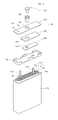
FIG. 1 is an exploded perspective of a secondary battery according to an embodiment of the invention. -
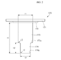
FIG. 2 is a cross-sectional view illustrating the electrode terminal of the secondary battery shown inFIG. 1 . -
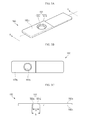
FIG. 3A is a perspective view illustrating the terminal plate of the secondary battery shown inFIG. 1 ,FIG. 3B is a bottom view of the terminal plate shown inFIG. 3A, and FIG. 3C is a cross-sectional view taken along the line A-A' ofFIG. 3A . -
FIG. 4 is a cross-sectional view of the secondary battery shown inFIG. 1 . -
FIG. 5 is an enlarged view of a portion 'B' shown inFIG. 4 . - Hereinafter, examples of embodiments of the invention will be described in detail with reference to the accompanying drawings such that they can easily be made and used by those skilled in the art.
- Referring to
FIGS. 1 to 5 , thesecondary battery 100 includes anelectrode assembly 110, acase 120, acap assembly 130 and an insulation case 180. - The
electrode assembly 110 includes apositive electrode plate 111, anegative electrode plate 112, and aseparator 113 interposed between the positive andnegative electrode plates positive electrode plate 111, thenegative electrode plate 112 and theseparator 113 are wound to have a jelly roll structure. - In more detail, the
electrode assembly 110 includes thepositive electrode plate 111 coated with a positive electrode active material, thenegative electrode plate 112 coated with a negative electrode active material, and theseparator 113 positioned between thepositive electrode plate 111 and thenegative electrode plate 112 to prevent an electric short therebetween while allowing lithium ions to move. Here, thepositive electrode plate 111 may include an aluminum (Al) foil, thenegative electrode plate 112 may include a copper (Cu) foil, and theseparator 113 may include polyethylene (PE) or polypropylene (PP). However, the described technology is not limited thereto. In addition, afirst electrode tab 114 protrudes upward by a predetermined length and is electrically connected to thepositive electrode plate 111. Asecond electrode tab 115 protrudes upward by a predetermined length and is electrically connected to thenegative electrode plate 112. Thefirst electrode tab 114 may include aluminum (Al), and thesecond electrode tab 115 may include nickel (Ni), but the described technology is not limited thereto. In addition, the polarities of the first andsecond electrode tabs - The
case 120 has atop opening 120a having an open top portion and is shaped like a substantially rectangular parallelepiped. That is to say, thecase 120 has a pair of long side portions 121 spaced a predetermined distance apart from each other and having relatively large areas, a pair of short side portions 122 having smaller areas than the pair of long side portions 121, and a bottom portion 123 formed on a bottom of the long side portions 121 and the short side portions 122 to be substantially perpendicular to the long side portions 121 and the short side portions 122. - The
case 120 can be formed by a deep drawing method so that the long side portions 121, the short side portions 122 and the bottom portion 123 are integrally formed. Here, thecase 120 may be formed of one material selected from the group of steel, aluminum and equivalents thereof, but is not limited thereto. - An electrolytic solution (not shown) and the
electrode assembly 110 are accommodated or housed in thecase 120. The electrolyte may serves as a movement medium for lithium ions generated by electrochemical reactions occurring in the positive andnegative electrode plates secondary battery 100. The electrolytic solution may be a non-aqueous organic electrolyte including a lithium salt and a high-purity organic solvent mixed therein. In addition, the electrolyte may be a polymer using a polymeric electrolyte. - The
cap assembly 130 includes acap plate 140, aninsulation plate 150, aterminal plate 160 and anelectrode terminal 170. Thecap assembly 130 is connected to a separate insulation case 180 and is attached to thetop opening 120a of thecase 120 to seal thecase 120. - The
cap plate 140 is formed of a metal plate sized and shaped to correspond to thetop opening 120a of thecan 120. Thefirst electrode tab 114 of theelectrode assembly 110 passes through the insulation case 180 and can be welded to a bottom surface of thecap plate 140. Thus, thecap plate 140 has the same polarity as thefirst electrode tab 114 of theelectrode assembly 110. - A terminal through hole or cap through
hole 141 is formed between top and bottom surfaces of thecap plate 140 and is substantially centrally located within thecap plate 140. Anelectrode terminal 170 is inserted into the terminal throughhole 141 and connected to the terminal throughhole 141. Atubular gasket 143 is mounted on an inner surface of the terminal throughhole 141 to electrically insulate theelectrode terminal 170 from the cap plate 131. Thegasket 143 is interposed between the terminal throughhole 141 and theelectrode terminal 170, makes close contact therewith and electrically isolates theelectrode terminal 170 and thecap plate 140 from each other. Thus, the terminal throughhole 141 of thecap plate 140 may be sized to correspond to the outer diameter of thegasket 143. - An
electrolyte injection hole 142 may further be provided at one side of thecap plate 140. Theelectrolyte injection hole 142 enables the injection of an electrolytic solution into an inner space of thecase 120 after thecap assembly 130 is assembled with thetop opening 120a of thecase 120. In addition, theelectrolyte injection hole 142 is sealed by aplug 144 after the electrolytic solution is injected into thecase 120. - The
insulation plate 150 can be formed of an electrically insulating material and is interposed between thecap plate 140 and theterminal plate 160 to electrically insulate thecap plate 140 and theterminal plate 160 from each other. Theinsulation plate 150 has a terminal through hole or insulation throughhole 151 located to correspond to the terminal throughhole 141 of thecap plate 140 to allow theelectrode terminal 170 to be inserted into the terminal throughhole 151. Theelectrode terminal 170 is inserted into the terminal throughhole 151 of theinsulation plate 150 and is connected to theinsulation plate 150. Agasket 143 may further be provided between the terminal throughhole 151 of theinsulation plate 150 and theelectrode terminal 170. In addition, the terminal throughhole 151 of theinsulation plate 150 may be sized to correspond to an outer diameter of thegasket 143. That is to say, the terminal throughhole 151 of theinsulation plate 150 may be sized to correspond to the terminal throughhole 141 of thecap plate 140. - The
terminal plate 160 may be formed of a metal plate configured such that itstop surface 160a makes close contact with a bottom surface of theinsulation plate 150. Abottom surface 160b of theterminal plate 160 faces a top surface of the insulation case 180. Thus, theterminal plate 160 is interposed between theinsulation plate 150 and the insulation case 180. Thetop surface 160a of theterminal plate 160 can have, for example, a smaller area than the bottom surface of theinsulation plate 150. Theterminal plate 160 is electrically isolated from thecap plate 140 by theinsulation plate 150. Thebottom surface 160b of theterminal plate 160 can be welded to thesecond electrode tab 115 of theelectrode assembly 110 having passed through the insulation case 180, so that theterminal plate 160 and theelectrode assembly 110 have the same polarity. - The
terminal plate 160 has a terminal throughhole 161 formed between thetop surface 160a and thebottom surface 160b and theelectrode terminal 170 is inserted into the terminal throughhole 161 and electrically connected to the terminal throughhole 161. The terminal throughhole 161 of theterminal plate 160 is located to correspond to the terminal throughhole 141 of thecap plate 140. - The terminal through
hole 161 includes a first terminal through hole orupper section 161a extending from thetop surface 160a toward thebottom surface 160b of theterminal plate 160 and a second terminal through hole orlower section 161b extending from thebottom surface 160b toward thetop surface 160a of theterminal plate 160. The first terminal throughhole 161a has a first inner diameter (a), the second terminal throughhole 161b has a second inner diameter b, and the first inner diameter a is less than the second inner diameter b. Thus, the first terminal throughhole 161a formed on thetop surface 160a of theterminal plate 160 and the second terminal throughhole 161b formed on thebottom surface 160b of theterminal plate 160 have different shapes and/or sizes. - In addition, the central axes of the first and second terminal through
holes holes hole 161 formed at least one step due to the difference in diameter between the first and second terminal throughholes - A lower region of the
electrode terminal 170 passes through the first terminal throughhole 161a of theterminal plate 160 and makes close contact with theterminal plate 160 through the bottom surface of the second terminal throughhole 161b. Accordingly, theterminal plate 160 is electrically connected to theelectrode terminal 170. - In order to make contact with an outer circumferential surface of the
electrode terminal 170, the first terminal throughhole 161a may be a circular hole having substantially the same shape as the body of theelectrode terminal 170. The second terminal throughhole 161b may have substantially the same circular shape with the first terminal throughhole 161a. Alternatively, the second terminal throughhole 161b may have a substantially polygonal shape, such as that of a rectangle. - The
electrode terminal 170 is inserted into terminal throughholes cap plate 140, theinsulation plate 150 and theterminal plate 160 to pass through the terminal throughholes electrode terminal 170 may be formed of a metal plate having a substantially cylindrical shape. - The
electrode terminal 170 includes ahead part 171 and anextension part 172 each horizontally extending a predetermined length from a top surface of thecap plate 140. Theelectrode terminal 170 also includes a first insertion part orbody 173 and a second insertion part ortail 174 each having a substantially cylindrical shape and inserted into the terminal throughholes cap plate 140, theinsulation plate 150 and theterminal plate 160. Thehead part 171 and theextension part 172 of theelectrode terminal 170 are electrically isolated from the top surface of thecap plate 140 by thegasket 143. Theelectrode terminal 170 is inserted into the terminal throughhole 161 of theterminal plate 160 to make contact with theterminal plate 160, so that theelectrode terminal 170 has the same polarity as thesecond electrode tab 115 electrically connected to theterminal plate 160. - The
head part 171 horizontally extends. In addition, theplate part 171 is a region exposed to the outside of thesecondary battery 100 and functions as an electrode having the same polarity with thesecond electrode tab 115 in a final structure. - The
extension part 172 is formed to be substantially parallel to thehead part 171 and may have a length that is less than that of thehead part 171. Theextension part 172 can efficiently prevent moisture from penetrating into thesecondary battery 100 and the electrolytic solution from leaking out of thesecondary battery 100 by increasing the contact area between theextension part 172 and thegasket 143. - The
first insertion part 173 has a substantially cylindrical shape and protrudes downward from theextension part 172. Thefirst insertion part 173 is formed to have a first length h1 and afirst thickness 11 and passes through the terminal throughhole 141 of thecap plate 140 and the terminal throughhole 151 of theinsulation plate 150. In addition, since the exterior surface of thefirst insertion part 173 is wrapped by thegasket 143, thecap plate 140 and thefirst electrode tab 114 are electrically insulated from each other. - The
first insertion part 173 is formed such that its bottom end is rounded having a first curvature radius r1. Here, the first curvature radius r1 may be about 0.01 mm or greater. When the first curvature radius r1 is about 0.01 mm, it is possible to prevent cracks from being generated in theterminal plate 160 when thefirst insertion part 173 is inserted into the terminal through hole of theterminal plate 160 by spinning. However, an upper limit of the first curvature radius r1 is not specifically preset because it is advantageous to set the first curvature radius r1 to be larger in order to prevent cracks from being generated. However, in other embodiments, the first curvature radius r1 is less than about 0.01 mm. - The
second insertion part 174 has a substantially cylindrical shape and extends from a bottom end of thefirst insertion part 172. Thesecond insertion part 174 is formed to have substantially the same center as thefirst insertion part 174 so as to facilitate insertion of theelectrode terminal 170 by spinning. Thesecond insertion part 174 has a second length h2 and asecond thickness 12. - Here, the second length h2 of the
second insertion part 174 extending from the end of thesecond insertion part 174 connected to thefirst insertion part 173 may be about 0.1 mm or greater. When the second length h2 of thesecond insertion part 174 is greater than or substantially equal to about 0.1 mm, thesecond insertion part 174 may spread out by being rotated in a spinning process for being connected to theterminal plate 160. Accordingly, thesecond insertion part 174 can be deformed such that it makes contact with the second terminal throughhole 161b having the second inner diameter b. In addition, contact resistance between thesecond insertion part 174 and theterminal plate 160 can be reduced by increasing the contact area between the deformedsecond insertion part 174 and the second terminal throughhole 161b of theterminal plate 160. However, the upper limit of the second length h2 is not specifically preset because it is advantageous to set the second length h2 of thesecond insertion part 174 to be greater in order to reduce the contact resistance. However, in other embodiments, the second length h2 may be less than about 0.1 mm. - The
second thickness 12 of thesecond insertion part 174 is less than thefirst thickness 11 of thefirst insertion part 173. Here, thesecond thickness 12 may be greater than or substantially equal to about 0.05 mm. When thefirst insertion part 173 has various thicknesses, thesecond insertion part 174 may have an area set to be greater than or substantially equal to about 20% of the area of thefirst insertion part 173. Generally, when thesecond thickness 12 is greater than or substantially equal to about 0.05 mm, thesecond insertion part 174 may sufficiently spread out in a spinning process to then make contact with the second terminal throughhole 161b having the second inner diameter b. In addition, if the area of thesecond insertion part 174 is greater than or substantially equal to about 20% of the area of thefirst insertion part 173, thesecond insertion part 174 may sufficiently spread out in the spinning process. However, in other embodiments, thesecond thickness 12 is less than about 0.05 mm and the area of thesecond insertion part 174 is less than about 20% of the area of thefirst insertion part 173. - In addition, the
second thickness 12 of thesecond insertion part 174 may be about half (1/2) or less of thefirst thickness 11 of thefirst insertion part 173. In addition, when thesecond thickness 12 of thesecond insertion part 174 is less than or substantially equal to about half of thefirst thickness 11 of thefirst insertion part 173, a sufficiently low contact resistance between thesecond insertion part 174 and theterminal plate 160 can be obtained. However, in other embodiments, thesecond thickness 12 is greater than about half of thefirst thickness 11. - In addition, the bottom end of the
second insertion part 174 may be rounded to have a second curvature radius r2. The bottom end of thesecond insertion part 174 can prevent theterminal plate 160 from being damaged in the spinning process. To this end, the second curvature radius r2 may be about 0.01 mm or greater. If the second curvature radius r2 is greater than or substantially equal to about 0.01 mm, theterminal plate 160 can be prevented from being damaged. Accordingly, the upper limit of the second curvature radius r2 is not specifically preset. However, in other embodiments, the second curvature radius r2 is less than about 0.01 mm. - Referring to
FIGS. 4 and 5 , the bottom of thesecond insertion part 174 is deformed by spinning to be connected to the bottom surface of theterminal plate 160. If thesecond insertion part 174 spreads out by spinning, it is connected to the bottom surface of theterminal plate 160. In particular, thesecond insertion part 174 spreads out along the second terminal throughhole 161b of theterminal plate 160 to be connected to theterminal plate 160. Therefore, the bottom end of thesecond insertion part 174 is electrically connected to theterminal plate 160. Here, thelength 13 of thesecond insertion part 174 that is deformed and spread out is less than or substantially equal to the inner diameter of the second terminal throughhole 161b. Therefore, the bottom end of thesecond insertion part 174 may be stably connected to the second terminal throughhole 161b. In one embodiment, the spinning of the electrode terminal is performed by a motor (not illustrated) at a speed that enables the material of the electrode terminal to be spread out. - Further, as shown in
FIG. 5 , after thesecond insertion part 174 is spread out it includes upper and lower ends 174 and 175 having different thicknesses. Theupper end 174 has thesecond thickness 12 that substantially equals the first inner diameter a of the first terminal throughhole 161a. Thelower end 175 has the third thickness orlength 13 that is less than or substantially equal to the second inner diameter b. - As can be seen in
FIG. 5 , thesecond insertion part 174 has a second thickness (a) less than a first thickness offirst insertion part 173. Andlower end 175 has a thickness (b) bigger than the second thickness (a). Thus, theterminal plate 160 can be fixed between thefirst insertion part 173 and thelower end 175 around thesecond insertion part 174 easily and stably, and damage to theterminal plate 160 can be reduced. - The insulation case 180 is formed of an electrically insulating material and is interposed between the
cap assembly 130 and theelectrode assembly 110 to electrically insulate thecap assembly 130 and theelectrode assembly 110 from each other. In addition, the insulation case 180 includes a pair of tab holes to allow thefirst electrode tab 114 and thesecond electrode tab 115 of thecap assembly 130 to upwardly protrude therethrough. Thus, the insulation case 180 electrically insulates a top end ofelectrode assembly 110, from which thefirst electrode tab 114 and thesecond electrode tab 115 of theelectrode assembly 110 protrude, and thecap assembly 130 from each other. - FIG. 6 is a flowchart showing an operation or procedure 600 for manufacturing a secondary battery according to an embodiment. Depending on the embodiment, additional states may be added, others removed, or the order of the states changed in FIG. 6. In state 610, the
cap plate 140,insulation plate 150 andterminal plate 160 are assembled so as to form thecap assembly 130. In state 620, theelectrode terminal 170 is inserted into the terminal throughholes cap plate 140,insulation plate 150 andterminal plate 160. In state 630, theelectrode terminal 170 is spun so as to spread thetail 174 of theelectrode terminal 170. In some embodiments, a motor (not illustrated) is used to spin theelectrode terminal 170. In state 640, thecap assembly 130 is attached to thecase 120 including theelectrode assembly 110 so as to form thesecondary battery 100. - Although embodiments of the inventive technology have been described in detail hereinabove, it should be understood that many variations and modifications of the described inventive technology, which may be apparent to those skilled in the art, will still fall within the scope of the present invention as defined by the appended claims.
Claims (11)
- A secondary battery, comprising:an electrode assembly including a first electrode plate, a second electrode plate and a separator;a case having an opening and housing the electrode assembly and an electrolytic solution; anda cap assembly including a cap plate, an insulation plate, a terminal plate and an electrode terminal, wherein the cap assembly seals the opening,wherein the electrode terminal includes a body having a first thickness and a tail having a second thickness less than the first thickness.
- A secondary battery according to claim 1, wherein the electrode terminal is electrically connected to the terminal plate, wherein the tail has upper and lower ends, wherein the upper end has the second thickness and wherein the lower end has a third thickness greater than the second thickness.
- A secondary battery according to claim 2, wherein the upper end of the tail of the electrode terminal has an area that is greater than or substantially equal to about 20% of the area of the body of the electrode terminal.
- A secondary battery according to claim 1, 2 or 3 wherein the body of the electrode terminal has a first length, wherein the tail of the electrode terminal has a second length and wherein the second length is less than the first length.
- A secondary battery according to claim 4, wherein the second length is greater than or substantially equal to about 0.05 mm.
- A secondary battery of claim 4 or 5, wherein the second length is less than or substantially equal to about half of the first length.
- A secondary battery according to any preceding claim, wherein the body of the electrode terminal is connected to the tail of the electrode terminal at a junction having a rounded edge and wherein the rounded edge of the junction has a first curvature radius.
- A secondary battery according to claim 7, wherein the first curvature radius is greater than or substantially equal to about 0.1 mm.
- A secondary battery according to any preceding claim, wherein the terminal plate has a terminal through hole extending from a top surface to a bottom surface thereof, wherein the electrode terminal is inserted into the terminal through hole, and wherein the terminal through hole has a first diameter at the top surface of the terminal plate and a second diameter at the bottom surface of the terminal plate.
- A secondary battery according to claim 9, wherein the second diameter is greater than the first diameter.
- A secondary battery according to claim 9 or 10, wherein the tail of the electrode terminal is connected to the terminal plate and wherein the tail of the electrode terminal at least partially fills the portion of the terminal through hole having the second diameter.
Applications Claiming Priority (1)
| Application Number | Priority Date | Filing Date | Title |
|---|---|---|---|
| KR1020140023695A KR102154332B1 (en) | 2014-02-27 | 2014-02-27 | Secondary Battery |
Publications (2)
| Publication Number | Publication Date |
|---|---|
| EP2913868A1 true EP2913868A1 (en) | 2015-09-02 |
| EP2913868B1 EP2913868B1 (en) | 2018-05-02 |
Family
ID=52133982
Family Applications (1)
| Application Number | Title | Priority Date | Filing Date |
|---|---|---|---|
| EP14199063.0A Active EP2913868B1 (en) | 2014-02-27 | 2014-12-18 | Secondary battery and method of manufacturing the same |
Country Status (5)
| Country | Link |
|---|---|
| US (1) | US10388936B2 (en) |
| EP (1) | EP2913868B1 (en) |
| JP (1) | JP6647775B2 (en) |
| KR (1) | KR102154332B1 (en) |
| CN (1) | CN104882626B (en) |
Cited By (1)
| Publication number | Priority date | Publication date | Assignee | Title |
|---|---|---|---|---|
| EP2924767A3 (en) * | 2014-02-27 | 2015-11-18 | Samsung SDI Co., Ltd. | Rechargeable battery |
Families Citing this family (12)
| Publication number | Priority date | Publication date | Assignee | Title |
|---|---|---|---|---|
| KR20150101864A (en) * | 2014-02-27 | 2015-09-04 | 삼성에스디아이 주식회사 | Secondary battery |
| JP6369625B2 (en) * | 2015-03-23 | 2018-08-08 | 三洋電機株式会社 | Power supply |
| JP6731176B2 (en) * | 2016-01-21 | 2020-07-29 | 株式会社Gsユアサ | Electric storage element and method for manufacturing electric storage element |
| JP6852629B2 (en) * | 2017-09-12 | 2021-03-31 | トヨタ自動車株式会社 | Power storage device |
| JP7252926B2 (en) | 2020-09-17 | 2023-04-05 | プライムプラネットエナジー&ソリューションズ株式会社 | SECONDARY BATTERY TERMINAL AND SECONDARY BATTERY INCLUDING THE TERMINAL |
| JP7256780B2 (en) | 2020-09-17 | 2023-04-12 | プライムプラネットエナジー&ソリューションズ株式会社 | SECONDARY BATTERY TERMINAL AND METHOD FOR MANUFACTURING SECONDARY BATTERY TERMINAL |
| JP7245208B2 (en) * | 2020-09-17 | 2023-03-23 | プライムプラネットエナジー&ソリューションズ株式会社 | SECONDARY BATTERY TERMINAL AND SECONDARY BATTERY INCLUDING THE TERMINAL |
| DE102021112325A1 (en) * | 2021-05-11 | 2022-11-17 | Bayerische Motoren Werke Aktiengesellschaft | battery cell |
| JP7402202B2 (en) | 2021-07-15 | 2023-12-20 | プライムプラネットエナジー&ソリューションズ株式会社 | Terminal components and terminal component manufacturing method |
| JP7426356B2 (en) | 2021-08-06 | 2024-02-01 | プライムプラネットエナジー&ソリューションズ株式会社 | Terminal parts and secondary batteries and assembled batteries equipped with the terminal parts |
| JP7405811B2 (en) * | 2021-10-22 | 2023-12-26 | プライムプラネットエナジー&ソリューションズ株式会社 | Terminal parts, secondary batteries, and methods of manufacturing terminal parts |
| US20250201986A1 (en) * | 2023-12-14 | 2025-06-19 | Sk On Co., Ltd. | Battery Cell and Manufacturing Method of the Same |
Citations (3)
| Publication number | Priority date | Publication date | Assignee | Title |
|---|---|---|---|---|
| EP1662601A1 (en) * | 2004-11-29 | 2006-05-31 | Samsung SDI Co., Ltd. | Lithium secondary battery |
| US20070154802A1 (en) * | 2005-12-29 | 2007-07-05 | Hwail Uh | Secondary battery |
| US20100136415A1 (en) * | 2008-11-28 | 2010-06-03 | Samsung Sdi Co., Ltd. | Insulating case for secondary battery and secondary battery having the same |
Family Cites Families (23)
| Publication number | Priority date | Publication date | Assignee | Title |
|---|---|---|---|---|
| JP3815561B2 (en) | 2001-11-29 | 2006-08-30 | 株式会社ジーエス・ユアサコーポレーション | Storage battery |
| JP4127618B2 (en) | 2002-03-19 | 2008-07-30 | 日立マクセル株式会社 | Sealed battery |
| GB2404231B (en) * | 2003-07-24 | 2006-09-06 | Newfrey Llc | Improved blind fastener and method of setting |
| GB0403109D0 (en) * | 2004-02-12 | 2004-03-17 | Hesco Bastion Ltd | Apparatus for the creation of outer surfaces for structures |
| KR101264425B1 (en) | 2006-07-24 | 2013-05-14 | 삼성에스디아이 주식회사 | Cap assembly and rechargeable battery using the same |
| KR101264461B1 (en) | 2006-08-07 | 2013-05-14 | 삼성에스디아이 주식회사 | Cap assembly and rechargeable battery using this same and assembly method of cap assembly |
| JP2009054531A (en) * | 2007-08-29 | 2009-03-12 | Toshiba Corp | battery |
| KR100854235B1 (en) | 2007-09-03 | 2008-08-25 | 삼성에스디아이 주식회사 | Can type lithium secondary battery |
| JP2009080975A (en) * | 2007-09-25 | 2009-04-16 | Toshiba Corp | Battery manufacturing method |
| JP2009087729A (en) | 2007-09-28 | 2009-04-23 | Toshiba Corp | Sealed battery |
| JP2010277785A (en) * | 2009-05-27 | 2010-12-09 | Sanyo Electric Co Ltd | Sealed battery and its manufacturing method |
| CH701238B1 (en) * | 2009-06-10 | 2013-12-13 | Luca Romelli | Calibration method for a device to hose of liquid insecurity connected to a pressure sensor. |
| JP5595830B2 (en) * | 2009-08-26 | 2014-09-24 | 株式会社東芝 | Battery, assembled battery, and method of manufacturing assembled battery |
| KR101127610B1 (en) * | 2010-04-12 | 2012-03-22 | 삼성에스디아이 주식회사 | Battery Pack |
| KR101211901B1 (en) * | 2010-05-25 | 2012-12-13 | 에스비리모티브 주식회사 | Secondary battery |
| CN105304835B (en) * | 2010-07-21 | 2018-10-12 | 株式会社东芝 | Battery and battery pack |
| US8916287B2 (en) * | 2010-08-16 | 2014-12-23 | Samsung Sdi Co., Ltd. | Rechargeable battery |
| JP2012248487A (en) | 2011-05-31 | 2012-12-13 | Mitsubishi Heavy Ind Ltd | Electrical appliance |
| EP2752920B1 (en) * | 2011-08-29 | 2017-11-01 | Toyota Jidosha Kabushiki Kaisha | Cell, assembled battery, and battery-mounted device |
| JP5941654B2 (en) * | 2011-10-27 | 2016-06-29 | 日立オートモティブシステムズ株式会社 | Single cells and batteries |
| JP5976340B2 (en) * | 2012-02-29 | 2016-08-23 | 三洋電機株式会社 | Method for manufacturing prismatic secondary battery |
| JP6089784B2 (en) * | 2013-02-28 | 2017-03-08 | 三洋電機株式会社 | Prismatic secondary battery |
| EP3062370B1 (en) * | 2013-10-25 | 2019-01-16 | Hitachi Automotive Systems, Ltd. | Rectangular secondary battery |
-
2014
- 2014-02-27 KR KR1020140023695A patent/KR102154332B1/en active Active
- 2014-07-23 JP JP2014149555A patent/JP6647775B2/en active Active
- 2014-11-19 US US14/547,921 patent/US10388936B2/en active Active
- 2014-12-18 EP EP14199063.0A patent/EP2913868B1/en active Active
-
2015
- 2015-02-16 CN CN201510083777.3A patent/CN104882626B/en active Active
Patent Citations (3)
| Publication number | Priority date | Publication date | Assignee | Title |
|---|---|---|---|---|
| EP1662601A1 (en) * | 2004-11-29 | 2006-05-31 | Samsung SDI Co., Ltd. | Lithium secondary battery |
| US20070154802A1 (en) * | 2005-12-29 | 2007-07-05 | Hwail Uh | Secondary battery |
| US20100136415A1 (en) * | 2008-11-28 | 2010-06-03 | Samsung Sdi Co., Ltd. | Insulating case for secondary battery and secondary battery having the same |
Non-Patent Citations (1)
| Title |
|---|
| VALLEY FASTENER GROUP LLC: "Shoulder rivets", 6 March 2012 (2012-03-06), XP002741482, Retrieved from the Internet <URL:https://web.archive.org/web/20120306134157/http://www.valleyfastener.com/shoulder-rivets.html> [retrieved on 20150626] * |
Cited By (1)
| Publication number | Priority date | Publication date | Assignee | Title |
|---|---|---|---|---|
| EP2924767A3 (en) * | 2014-02-27 | 2015-11-18 | Samsung SDI Co., Ltd. | Rechargeable battery |
Also Published As
| Publication number | Publication date |
|---|---|
| KR102154332B1 (en) | 2020-09-09 |
| CN104882626A (en) | 2015-09-02 |
| KR20150101862A (en) | 2015-09-04 |
| CN104882626B (en) | 2020-02-14 |
| US20150243955A1 (en) | 2015-08-27 |
| JP6647775B2 (en) | 2020-02-14 |
| EP2913868B1 (en) | 2018-05-02 |
| US10388936B2 (en) | 2019-08-20 |
| JP2015162460A (en) | 2015-09-07 |
Similar Documents
| Publication | Publication Date | Title |
|---|---|---|
| EP2913868B1 (en) | Secondary battery and method of manufacturing the same | |
| US9252401B2 (en) | Secondary battery | |
| US8956756B2 (en) | Secondary battery and battery pack including the same | |
| EP2958162B1 (en) | Secondary battery | |
| US8771854B2 (en) | Secondary battery | |
| US9093699B2 (en) | Rechargeable battery | |
| US8728644B2 (en) | Rechargeable battery | |
| US9136524B2 (en) | Secondary battery | |
| KR101254853B1 (en) | Secondary battery | |
| EP2518791B1 (en) | Terminal of secondarey battery and method of assembling the same | |
| US8771869B2 (en) | Secondary battery | |
| EP2597705A1 (en) | Rechargeable battery | |
| US20150243941A1 (en) | Secondary battery | |
| KR102470495B1 (en) | Secondary Battery and Method for Manufacturing The Same | |
| EP2642551B1 (en) | Secondary battery | |
| US9028999B2 (en) | Secondary battery | |
| US20160308188A1 (en) | Rechargeable battery | |
| US9806304B2 (en) | Secondary battery |
Legal Events
| Date | Code | Title | Description |
|---|---|---|---|
| PUAI | Public reference made under article 153(3) epc to a published international application that has entered the european phase |
Free format text: ORIGINAL CODE: 0009012 |
|
| AK | Designated contracting states |
Kind code of ref document: A1 Designated state(s): AL AT BE BG CH CY CZ DE DK EE ES FI FR GB GR HR HU IE IS IT LI LT LU LV MC MK MT NL NO PL PT RO RS SE SI SK SM TR |
|
| AX | Request for extension of the european patent |
Extension state: BA ME |
|
| 17P | Request for examination filed |
Effective date: 20160302 |
|
| RBV | Designated contracting states (corrected) |
Designated state(s): AL AT BE BG CH CY CZ DE DK EE ES FI FR GB GR HR HU IE IS IT LI LT LU LV MC MK MT NL NO PL PT RO RS SE SI SK SM TR |
|
| RIC1 | Information provided on ipc code assigned before grant |
Ipc: H01M 2/22 20060101ALN20170911BHEP Ipc: H01M 2/30 20060101AFI20170911BHEP Ipc: H01M 2/04 20060101ALN20170911BHEP |
|
| GRAP | Despatch of communication of intention to grant a patent |
Free format text: ORIGINAL CODE: EPIDOSNIGR1 |
|
| RIC1 | Information provided on ipc code assigned before grant |
Ipc: H01M 2/04 20060101ALN20170922BHEP Ipc: H01M 2/30 20060101AFI20170922BHEP Ipc: H01M 2/22 20060101ALN20170922BHEP |
|
| INTG | Intention to grant announced |
Effective date: 20171024 |
|
| GRAJ | Information related to disapproval of communication of intention to grant by the applicant or resumption of examination proceedings by the epo deleted |
Free format text: ORIGINAL CODE: EPIDOSDIGR1 |
|
| REG | Reference to a national code |
Ref country code: DE Ref legal event code: R079 Ref document number: 602014024787 Country of ref document: DE Free format text: PREVIOUS MAIN CLASS: H01M0002260000 Ipc: H01M0002300000 |
|
| GRAR | Information related to intention to grant a patent recorded |
Free format text: ORIGINAL CODE: EPIDOSNIGR71 |
|
| GRAS | Grant fee paid |
Free format text: ORIGINAL CODE: EPIDOSNIGR3 |
|
| GRAA | (expected) grant |
Free format text: ORIGINAL CODE: 0009210 |
|
| INTC | Intention to grant announced (deleted) | ||
| RIC1 | Information provided on ipc code assigned before grant |
Ipc: H01M 2/04 20060101ALN20180315BHEP Ipc: H01M 2/22 20060101ALN20180315BHEP Ipc: H01M 2/30 20060101AFI20180315BHEP |
|
| INTG | Intention to grant announced |
Effective date: 20180320 |
|
| AK | Designated contracting states |
Kind code of ref document: B1 Designated state(s): AL AT BE BG CH CY CZ DE DK EE ES FI FR GB GR HR HU IE IS IT LI LT LU LV MC MK MT NL NO PL PT RO RS SE SI SK SM TR |
|
| REG | Reference to a national code |
Ref country code: GB Ref legal event code: FG4D |
|
| REG | Reference to a national code |
Ref country code: CH Ref legal event code: EP Ref country code: AT Ref legal event code: REF Ref document number: 996182 Country of ref document: AT Kind code of ref document: T Effective date: 20180515 |
|
| REG | Reference to a national code |
Ref country code: DE Ref legal event code: R096 Ref document number: 602014024787 Country of ref document: DE |
|
| REG | Reference to a national code |
Ref country code: IE Ref legal event code: FG4D |
|
| REG | Reference to a national code |
Ref country code: NL Ref legal event code: MP Effective date: 20180502 |
|
| REG | Reference to a national code |
Ref country code: LT Ref legal event code: MG4D |
|
| PG25 | Lapsed in a contracting state [announced via postgrant information from national office to epo] |
Ref country code: FI Free format text: LAPSE BECAUSE OF FAILURE TO SUBMIT A TRANSLATION OF THE DESCRIPTION OR TO PAY THE FEE WITHIN THE PRESCRIBED TIME-LIMIT Effective date: 20180502 Ref country code: BG Free format text: LAPSE BECAUSE OF FAILURE TO SUBMIT A TRANSLATION OF THE DESCRIPTION OR TO PAY THE FEE WITHIN THE PRESCRIBED TIME-LIMIT Effective date: 20180802 Ref country code: NO Free format text: LAPSE BECAUSE OF FAILURE TO SUBMIT A TRANSLATION OF THE DESCRIPTION OR TO PAY THE FEE WITHIN THE PRESCRIBED TIME-LIMIT Effective date: 20180802 Ref country code: SE Free format text: LAPSE BECAUSE OF FAILURE TO SUBMIT A TRANSLATION OF THE DESCRIPTION OR TO PAY THE FEE WITHIN THE PRESCRIBED TIME-LIMIT Effective date: 20180502 Ref country code: ES Free format text: LAPSE BECAUSE OF FAILURE TO SUBMIT A TRANSLATION OF THE DESCRIPTION OR TO PAY THE FEE WITHIN THE PRESCRIBED TIME-LIMIT Effective date: 20180502 Ref country code: LT Free format text: LAPSE BECAUSE OF FAILURE TO SUBMIT A TRANSLATION OF THE DESCRIPTION OR TO PAY THE FEE WITHIN THE PRESCRIBED TIME-LIMIT Effective date: 20180502 |
|
| PG25 | Lapsed in a contracting state [announced via postgrant information from national office to epo] |
Ref country code: HR Free format text: LAPSE BECAUSE OF FAILURE TO SUBMIT A TRANSLATION OF THE DESCRIPTION OR TO PAY THE FEE WITHIN THE PRESCRIBED TIME-LIMIT Effective date: 20180502 Ref country code: GR Free format text: LAPSE BECAUSE OF FAILURE TO SUBMIT A TRANSLATION OF THE DESCRIPTION OR TO PAY THE FEE WITHIN THE PRESCRIBED TIME-LIMIT Effective date: 20180803 Ref country code: LV Free format text: LAPSE BECAUSE OF FAILURE TO SUBMIT A TRANSLATION OF THE DESCRIPTION OR TO PAY THE FEE WITHIN THE PRESCRIBED TIME-LIMIT Effective date: 20180502 Ref country code: NL Free format text: LAPSE BECAUSE OF FAILURE TO SUBMIT A TRANSLATION OF THE DESCRIPTION OR TO PAY THE FEE WITHIN THE PRESCRIBED TIME-LIMIT Effective date: 20180502 Ref country code: RS Free format text: LAPSE BECAUSE OF FAILURE TO SUBMIT A TRANSLATION OF THE DESCRIPTION OR TO PAY THE FEE WITHIN THE PRESCRIBED TIME-LIMIT Effective date: 20180502 |
|
| REG | Reference to a national code |
Ref country code: AT Ref legal event code: MK05 Ref document number: 996182 Country of ref document: AT Kind code of ref document: T Effective date: 20180502 |
|
| PG25 | Lapsed in a contracting state [announced via postgrant information from national office to epo] |
Ref country code: CZ Free format text: LAPSE BECAUSE OF FAILURE TO SUBMIT A TRANSLATION OF THE DESCRIPTION OR TO PAY THE FEE WITHIN THE PRESCRIBED TIME-LIMIT Effective date: 20180502 Ref country code: AT Free format text: LAPSE BECAUSE OF FAILURE TO SUBMIT A TRANSLATION OF THE DESCRIPTION OR TO PAY THE FEE WITHIN THE PRESCRIBED TIME-LIMIT Effective date: 20180502 Ref country code: EE Free format text: LAPSE BECAUSE OF FAILURE TO SUBMIT A TRANSLATION OF THE DESCRIPTION OR TO PAY THE FEE WITHIN THE PRESCRIBED TIME-LIMIT Effective date: 20180502 Ref country code: RO Free format text: LAPSE BECAUSE OF FAILURE TO SUBMIT A TRANSLATION OF THE DESCRIPTION OR TO PAY THE FEE WITHIN THE PRESCRIBED TIME-LIMIT Effective date: 20180502 Ref country code: DK Free format text: LAPSE BECAUSE OF FAILURE TO SUBMIT A TRANSLATION OF THE DESCRIPTION OR TO PAY THE FEE WITHIN THE PRESCRIBED TIME-LIMIT Effective date: 20180502 Ref country code: PL Free format text: LAPSE BECAUSE OF FAILURE TO SUBMIT A TRANSLATION OF THE DESCRIPTION OR TO PAY THE FEE WITHIN THE PRESCRIBED TIME-LIMIT Effective date: 20180502 Ref country code: SK Free format text: LAPSE BECAUSE OF FAILURE TO SUBMIT A TRANSLATION OF THE DESCRIPTION OR TO PAY THE FEE WITHIN THE PRESCRIBED TIME-LIMIT Effective date: 20180502 |
|
| REG | Reference to a national code |
Ref country code: DE Ref legal event code: R097 Ref document number: 602014024787 Country of ref document: DE |
|
| PG25 | Lapsed in a contracting state [announced via postgrant information from national office to epo] |
Ref country code: SM Free format text: LAPSE BECAUSE OF FAILURE TO SUBMIT A TRANSLATION OF THE DESCRIPTION OR TO PAY THE FEE WITHIN THE PRESCRIBED TIME-LIMIT Effective date: 20180502 Ref country code: IT Free format text: LAPSE BECAUSE OF FAILURE TO SUBMIT A TRANSLATION OF THE DESCRIPTION OR TO PAY THE FEE WITHIN THE PRESCRIBED TIME-LIMIT Effective date: 20180502 |
|
| PLBE | No opposition filed within time limit |
Free format text: ORIGINAL CODE: 0009261 |
|
| STAA | Information on the status of an ep patent application or granted ep patent |
Free format text: STATUS: NO OPPOSITION FILED WITHIN TIME LIMIT |
|
| 26N | No opposition filed |
Effective date: 20190205 |
|
| PG25 | Lapsed in a contracting state [announced via postgrant information from national office to epo] |
Ref country code: SI Free format text: LAPSE BECAUSE OF FAILURE TO SUBMIT A TRANSLATION OF THE DESCRIPTION OR TO PAY THE FEE WITHIN THE PRESCRIBED TIME-LIMIT Effective date: 20180502 |
|
| REG | Reference to a national code |
Ref country code: CH Ref legal event code: PL |
|
| PG25 | Lapsed in a contracting state [announced via postgrant information from national office to epo] |
Ref country code: LU Free format text: LAPSE BECAUSE OF NON-PAYMENT OF DUE FEES Effective date: 20181218 Ref country code: MC Free format text: LAPSE BECAUSE OF FAILURE TO SUBMIT A TRANSLATION OF THE DESCRIPTION OR TO PAY THE FEE WITHIN THE PRESCRIBED TIME-LIMIT Effective date: 20180502 |
|
| REG | Reference to a national code |
Ref country code: IE Ref legal event code: MM4A |
|
| REG | Reference to a national code |
Ref country code: BE Ref legal event code: MM Effective date: 20181231 |
|
| PG25 | Lapsed in a contracting state [announced via postgrant information from national office to epo] |
Ref country code: IE Free format text: LAPSE BECAUSE OF NON-PAYMENT OF DUE FEES Effective date: 20181218 |
|
| PG25 | Lapsed in a contracting state [announced via postgrant information from national office to epo] |
Ref country code: AL Free format text: LAPSE BECAUSE OF FAILURE TO SUBMIT A TRANSLATION OF THE DESCRIPTION OR TO PAY THE FEE WITHIN THE PRESCRIBED TIME-LIMIT Effective date: 20180502 Ref country code: BE Free format text: LAPSE BECAUSE OF NON-PAYMENT OF DUE FEES Effective date: 20181231 |
|
| PG25 | Lapsed in a contracting state [announced via postgrant information from national office to epo] |
Ref country code: CH Free format text: LAPSE BECAUSE OF NON-PAYMENT OF DUE FEES Effective date: 20181231 Ref country code: LI Free format text: LAPSE BECAUSE OF NON-PAYMENT OF DUE FEES Effective date: 20181231 |
|
| PG25 | Lapsed in a contracting state [announced via postgrant information from national office to epo] |
Ref country code: MT Free format text: LAPSE BECAUSE OF NON-PAYMENT OF DUE FEES Effective date: 20181218 |
|
| PG25 | Lapsed in a contracting state [announced via postgrant information from national office to epo] |
Ref country code: TR Free format text: LAPSE BECAUSE OF FAILURE TO SUBMIT A TRANSLATION OF THE DESCRIPTION OR TO PAY THE FEE WITHIN THE PRESCRIBED TIME-LIMIT Effective date: 20180502 |
|
| PG25 | Lapsed in a contracting state [announced via postgrant information from national office to epo] |
Ref country code: PT Free format text: LAPSE BECAUSE OF FAILURE TO SUBMIT A TRANSLATION OF THE DESCRIPTION OR TO PAY THE FEE WITHIN THE PRESCRIBED TIME-LIMIT Effective date: 20180502 |
|
| PG25 | Lapsed in a contracting state [announced via postgrant information from national office to epo] |
Ref country code: MK Free format text: LAPSE BECAUSE OF NON-PAYMENT OF DUE FEES Effective date: 20180502 Ref country code: HU Free format text: LAPSE BECAUSE OF FAILURE TO SUBMIT A TRANSLATION OF THE DESCRIPTION OR TO PAY THE FEE WITHIN THE PRESCRIBED TIME-LIMIT; INVALID AB INITIO Effective date: 20141218 Ref country code: CY Free format text: LAPSE BECAUSE OF FAILURE TO SUBMIT A TRANSLATION OF THE DESCRIPTION OR TO PAY THE FEE WITHIN THE PRESCRIBED TIME-LIMIT Effective date: 20180502 |
|
| PG25 | Lapsed in a contracting state [announced via postgrant information from national office to epo] |
Ref country code: IS Free format text: LAPSE BECAUSE OF FAILURE TO SUBMIT A TRANSLATION OF THE DESCRIPTION OR TO PAY THE FEE WITHIN THE PRESCRIBED TIME-LIMIT Effective date: 20180902 |
|
| REG | Reference to a national code |
Ref country code: DE Ref legal event code: R079 Ref document number: 602014024787 Country of ref document: DE Free format text: PREVIOUS MAIN CLASS: H01M0002300000 Ipc: H01M0050543000 |
|
| P01 | Opt-out of the competence of the unified patent court (upc) registered |
Effective date: 20230528 |
|
| PGFP | Annual fee paid to national office [announced via postgrant information from national office to epo] |
Ref country code: DE Payment date: 20251126 Year of fee payment: 12 |
|
| PGFP | Annual fee paid to national office [announced via postgrant information from national office to epo] |
Ref country code: GB Payment date: 20251127 Year of fee payment: 12 |
|
| PGFP | Annual fee paid to national office [announced via postgrant information from national office to epo] |
Ref country code: FR Payment date: 20251128 Year of fee payment: 12 |