EP2913666A2 - Method for inspecting honeycomb structure - Google Patents
Method for inspecting honeycomb structure Download PDFInfo
- Publication number
- EP2913666A2 EP2913666A2 EP15156489.5A EP15156489A EP2913666A2 EP 2913666 A2 EP2913666 A2 EP 2913666A2 EP 15156489 A EP15156489 A EP 15156489A EP 2913666 A2 EP2913666 A2 EP 2913666A2
- Authority
- EP
- European Patent Office
- Prior art keywords
- cell
- cells
- honeycomb structure
- measurement
- inscribed circle
- Prior art date
- Legal status (The legal status is an assumption and is not a legal conclusion. Google has not performed a legal analysis and makes no representation as to the accuracy of the status listed.)
- Granted
Links
Images



Classifications
-
- G—PHYSICS
- G01—MEASURING; TESTING
- G01N—INVESTIGATING OR ANALYSING MATERIALS BY DETERMINING THEIR CHEMICAL OR PHYSICAL PROPERTIES
- G01N21/00—Investigating or analysing materials by the use of optical means, i.e. using sub-millimetre waves, infrared, visible or ultraviolet light
- G01N21/84—Systems specially adapted for particular applications
- G01N21/88—Investigating the presence of flaws or contamination
- G01N21/95—Investigating the presence of flaws or contamination characterised by the material or shape of the object to be examined
- G01N21/956—Inspecting patterns on the surface of objects
- G01N21/95692—Patterns showing hole parts, e.g. honeycomb filtering structures
Definitions
- the present invention relates to a method for inspecting honeycomb structure. More specifically, the present invention relates to a method for inspecting honeycomb structure that allows simply inspecting a deformation state of cells open to an end face of a honeycomb structure.
- the honeycomb structure is a tubular construction that has a partition wall.
- the partition wall defines a plurality of cells extending from a first end face, which is one of an end face, to a second end face, which is the other end face.
- Such ceramic honeycomb structure may generate various defects during the manufacturing process.
- a method for inspecting the defect of the honeycomb structure is mainly a visual inspection by a person, an inspection of a size of a cell with pin gage, an inspection for clogging using light, or a similar method.
- a method for detecting a defect occurred in the honeycomb structure there has been proposed a method (method for inspecting an end face) for detecting a defect of an end face by taking an image of an end face of a honeycomb structure with camera (for example, see Patent Document 1).
- the cell deformation defect is possibly inspected by image processing.
- a considerably large number of cells are open to the end face of the honeycomb structure. Accordingly, inspecting the all cells for cell deformation defect causes a problem of requiring considerably long inspection time.
- this inspection for cell deformation defect may be a rate-determining process.
- the inspection for cell deformation defect is desirable to be performed on all cells of all manufactured honeycomb structures and substantially all cells at the end face of the one honeycomb structure. In view of this, an inspection method that can simply inspect the cell deformation defect, rather than methods of sampling inspection and an inspection on only a part of the end face of the honeycomb structure, has been urgent desired to be developed.
- the present invention has been developed in view of the above-mentioned problems, and an object of the present invention is to provide a method for inspecting honeycomb structure that can simply inspect the cell deformation defect at the end face of the honeycomb structure.
- the following method for inspecting honeycomb structure is provided.
- a method for inspecting honeycomb structure of the present invention inspects cell deformation defect of a honeycomb structure by measuring a size of an inscribed circle of a "measurement cell.”
- the inscribed circle is internally in contact with a partition wall that defines these measurement cells.
- the "measurement cell” is a specific cell open to a first end face of the honeycomb structure. In the method for inspecting honeycomb structure according to the present invention, the cell deformation defect of the honeycomb structure can be easily inspected.
- the all cells at the first end face of the honeycomb structure can be substantially inspected for cell deformation defect. Accordingly, inspection time required for inspection for the cell deformation defect can be shortened. To obtain an inspection result of the cell deformation defect, even if a processing unit performs various arithmetic operations, an amount of arithmetic operation is reduced. Accordingly, even without using the processing unit with high arithmetic processing capability, the inspection result can be relatively quickly obtained.
- One embodiment of the method for inspecting honeycomb structure of the present invention is an inspection method that inspects a honeycomb structure 10 with a partition wall 1 as shown in Fig. 1 to Fig. 3 .
- the partition wall defines a plurality of cells 2.
- the plurality of cells 2 penetrate from a first end face 11 to a second end face 12.
- the honeycomb structure 10 shown in Fig. 1 to Fig. 3 has the partition wall 1 and a circumferential wall 3.
- the partition wall 1 defines the cells 2.
- the circumferential wall 3 is disposed at an outermost circumference.
- the honeycomb structure 10 is preferable to be a ceramic honeycomb structure. Further, the honeycomb structure 10 is more preferable to have the porous, ceramic partition wall 1.
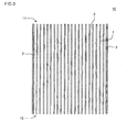
- FIG. 1 is a perspective view schematically showing the honeycomb structure of the inspection target of the method for inspecting honeycomb structure of the present invention.
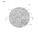
- Fig. 2 is a plan view schematically showing the first end face of the honeycomb structure shown in Fig. 1 .
- Fig. 3 is a cross-sectional view schematically showing a cross section taken along the line A-A' of Fig. 2 .
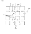
- the method for inspecting honeycomb structure of this embodiment is an inspection method to inspect presence/absence of a cell deformation 7 as shown in Fig. 4 .
- the cell deformation 7 occurs in the cell 2 open to the end face (for example, the first end face in Fig. 4 ) of the honeycomb structure 10 when the partition wall 1 of the honeycomb structure 10 is distorted.
- the "cell deformation 7" formed at the cell 2 may be referred to as a "cell deformation defect 7a.”
- the cells indicated by reference numeral 2a in Fig. 4 are cells 2a where the cell deformation defect 7a is absent.
- the cells indicated by reference numeral 2b in Fig. 4 are cells 2b where the cell deformation defects 7a are present.
- Fig. 4 is an enlarged plan where a range indicated by a dashed line B in Fig. 2 is enlarged.
- the method for inspecting honeycomb structure of this embodiment is an inspection method that includes a process A.
- the process A measures a size of an inscribed circle internally in contact with the partition wall, which defines these cells.
- the size of the inscribed circle in at least one cell among the plurality of cells open to the first end face of the honeycomb structure is measured. That is, the process A measures the size of the inscribed circle internally in contact with the partition wall 1, which defines these cells 2.
- the size of the inscribed circle in the cell 2 open to the first end face 11 of the honeycomb structure 10 as shown in Fig. 1 and Fig. 2 is measured.
- the process A inspects the cell deformation defect of the honeycomb structure 10.
- This process A does not measure the size of the inscribed circles of the all cells 2 open to the first end face 11 of the honeycomb structure 10, but measures a size of an inscribed circle of a predetermined cell. Then, the respective measured sizes of the inscribed circles are compared with a predetermined base value. Thus, the honeycomb structure 10 is inspected for cell deformation defect.
- the method for inspecting honeycomb structure of this embodiment selects the cell where the size of the inscribed circle is to be measured so as to meet the following conditions. The method then measures the size of the inscribed circle of the selected predetermined cell.
- the conditions in the process A are as follows.
- the cell where the size of the inscribed circle internally in contact with the partition wall is measured is referred to as a "measurement cell", and a cell where the size of the inscribed circle internally in contact with the partition wall is not to be measured is referred to as a "non-measurement cell.”
- a first condition at least one cell among the cells adjacent to one measurement cell separated by the partition wall is set as the non-measurement cell where the size of the inscribed circle is not to be measured.
- condition 2 at least one cell among the cells adjacent to one non-measurement cell separated by the partition wall is set as the measurement cell where the size of the inscribed circle is to be measured.
- the method for inspecting honeycomb structure of this embodiment is characterized by selecting the measurement cell or the non-measurement cell so as to meet these condition 1 and condition 2, and performing the inspection for cell deformation defect. The following further describes the inspection method in detail.
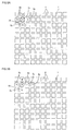
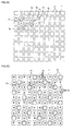
- Fig. 5A, Fig. 5B , Fig. 5C, and Fig. 5D are explanatory drawings, which show an exemplary procedure for measuring the inscribed circle in the process A.
- Fig. 5A, Fig. 5B , Fig. 5C, and Fig. 5D are enlarged plan views where a part of the first end face of the honeycomb structure is enlarged.
- measurement cells 2x and non-measurement cells 2y are sequentially selected in the order of Fig. 5B , Fig. 5C, and Fig. 5D from the state shown in Fig. 5A .
- the size of the inscribed circle 15 of the measurement cell 2x is measured.
- Fig. 5A, Fig. 5B , Fig. 5C, and Fig. 5D show an example where the shape of the cell 2 open to the first end face of the honeycomb structure is a quadrangular shape.
- At least one cell 2 among the cells 2 adjacent to the measurement cell 2x separated by the partition wall 1 is set as a non-measurement cell 2y. Moreover, at least one cell 2 among the cells 2 adjacent to the non-measurement cell 2y separated by the partition wall 1 is set as the measurement cell 2x.
- the measurement cell 2x For example, as shown in Fig. 5A , assume the case where the cell indicated by reference numeral "a" is the measurement cell 2x. Then, at least one cell 2 among the four cells 2 adjacent to the measurement cell 2x separated by the partition wall 1 is set as the non-measurement cell 2y.
- a cell adjacent to a predetermined cell separated by the partition wall may be simply referred to as an "adjacent cell.” In Fig.
- the measurement cell 2x sets the cell (cell indicated by reference numeral "g") lower next to the non-measurement cell 2y, which is indicated by reference numeral "f", on the paper is set as the measurement cell 2x.
- the measurement cell 2x or the non-measurement cell 2y is selected by the method similar to the procedure described above such that the cells 2 adjacent to these other cells meet the above-described condition 1 and condition 2.
- the remaining three cells are set as the non-measurement cells 2y.
- the measurement cell 2x and the non-measurement cell 2y are selected.
- the size of the inscribed circle 15 of the measurement cell 2x is measured.
- the size of the inscribed circle 15 of only the specific measurement cell 2x is measured. This constitution allows omitting measurement of the size of the inscribed circle 15 of the non-measurement cell 2y. This ensures simplifying a sequence of the operations of measuring the size of the inscribed circles 15.
- the cells 2 in which a small black circle is drawn are the non-measurement cells 2y.
- the cells 2 in which the inscribed circle 15 is drawn are the measurement cells 2x.
- the inscribed circle 15 drawn in the measurement cell 2x is an imaginary line drawn when measuring the size of the inscribed circle 15.
- the inscribed circle 15 is not directly drawn to the first end face 11 of the honeycomb structure 10 shown in Fig. 1 and Fig. 2 .
- an imaging means takes an image of the first end face 11 of the honeycomb structure 10.
- the imaginary inscribed circle 15 (see Fig. 5D ) is drawn to the obtained image.
- the size of this inscribed circle 15 can be measured.
- the "inscribed circle” means a circle inside of a polygonal cell.
- the polygonal cells are defined by the partition wall.
- the inscribed circle is the largest circle (in other words, the circle with the largest diameter) internally in contact with this polygonal shape.
- the example shown in Fig. 5D sets all the four cells 2 adjacent to the one measurement cell 2x as the non-measurement cells 2y. Further, one cell among the four cells 2 adjacent to the non-measurement cell 2y is set as the measurement cell 2x. Thus, the measurement cell 2x and the non-measurement cell 2y are selected. By thus selecting the measurement cell 2x and the non-measurement cell 2y, even if the all cells 2 are not the measurement cells 2x, the cell deformation defect can be substantially inspected on the all cells 2 open to the first end face 11 of the honeycomb structure 10.
- the inventor has focused on a fact that another cell adjacent to this cell and sharing the partition wall with this cell is also affected by the cell deformation defect.
- the present invention has been completed.
- the method for inspecting honeycomb structure of this embodiment if the cell deformation defect occurs in one cell, at least one cell among this one cell and the cells adjacent to this one cell becomes the measurement cell where the size of the inscribed circle is to be measured. Then, the measured size of the inscribed circle is compared with a predetermined criterion. This allows inspecting the presence/absence of cell deformation defect of the measurement cell and the cells adjacent to this measurement cell.
- the procedure for selecting the measurement cell and the non-measurement cell described above allows effectively preventing a situation where the non-measurement cells continuously exist and a place where the cell deformation defect is not inspected exists.
- Providing the non-measurement cell allows shorting inspection time required for the inspection for cell deformation defect. To obtain an inspection result of the cell deformation defect, even if a processing unit performs various arithmetic operations, an amount of arithmetic operation is reduced. Accordingly, even without using the processing unit with high arithmetic processing capability, the inspection result can be relatively quickly obtained.
- the method for inspecting honeycomb structure of this embodiment is preferable to further include a process B of taking an image of the first end face of the honeycomb structure by an imaging means.
- the size of the inscribed circle is preferable to be measured in the image taken by the process B.
- an inspection apparatus 100 as shown in Fig. 6 can be used.
- Fig. 6 is a perspective view schematically showing an exemplary inspection apparatus used for one embodiment of the method for inspecting honeycomb structure of the present invention.
- the inspection apparatus 100 shown in Fig. 6 includes an imaging means 31 and an image analysis means 32. It is preferred that the image analysis means 32 include an analysis means 34.
- the analysis means 34 measures the size of the inscribed circle internally in contact with the partition wall 1 (for example, see Fig.
- the image analysis means 32 may include a display means 35.
- the display means 35 can display an image 36, which is taken by the imaging means 31.
- the image analysis means 32 may include storage means 33.
- the storage means 33 stores the image 36, which is taken by the imaging means 31, as data.
- Reference numeral 37 in Fig. 6 denotes a wiring for transmitting data from the imaging means 31 to the image analysis means 32.
- an image analyzer such as "NEXIV, VMR-1515" (product name) manufactured by Nikon Corporation can be used. Using such image analyzer, it is preferred to measure the size of the inscribed circle internally in contact with the partition wall, which defines these cells, regarding at least one cell among the plurality of cells open to the first end face of the honeycomb structure.
- the measurement cell 2x and the non-measurement cell 2y are selected such that the four cells 2 adjacent to the one measurement cell 2x become the non-measurement cells 2y. Then, the size of the inscribed circles 15 is measured. However, with the method for inspecting honeycomb structure of this embodiment, it is only necessary to measure the size of the inscribed circle 15 of the measurement cell 2x so as to meet the above-described condition 1 and condition 2. For example, Fig. 7 shows an example where all the four cells 2 adjacent to this measurement cell 2x become the non-measurement cells 2y with respect to the one measurement cell 2x. Fig.
- FIG. 7 shows an example where one or three cells among the four cells adjacent to the non-measurement cell 2y is the measurement cell 2x with respect to this one non-measurement cell 2y.
- Fig. 7 shows an example where the cells corresponding to one-third pieces with respect to the total number of cells become the measurement cells 2x.
- the size of the inscribed circle 15 may be measured by selecting the measurement cell 2x and the non-measurement cell 2y as shown in Fig. 7 .
- Fig. 7 is an explanatory drawing showing another exemplary procedure for measuring the inscribed circle in the process A.
- the two cells 2 right next to and lower next to the one measurement cell 2x on the paper are set as the non-measurement cells 2y. Setting these three cells as one set, this set is repeatedly disposed at the end face of the honeycomb structure.
- the above-described inspection method describes an example where the cell 2 has a quadrangular shape.
- the shape of the cell 2 is not limited to the quadrangular shape. That is, the method for inspecting honeycomb structure of this embodiment can inspect a honeycomb structure with cells open to the first end face having a polygonal shape with three or more apexes.
- the cells open to the first end face are preferable to have a quadrangular shape or a hexagon shape.
- the shape of cell open to the first end face may be simply described as a "shape of cell.” For example, in the case where the shape of cell is the hexagon, as shown in Fig.
- a measurement cell 42x and a non-measurement cell 42y may be selected and the size of an inscribed circle 55 may be measured.
- Fig. 8 with respect to the one measurement cell 42x, six cells 42 adjacent to this measurement cell 42x separated by a partition wall 41 is set as non-measurement cells 42y. With respect to the one non-measurement cell 42y, two cells 42 among the six cells 42 adjacent to these non-measurement cells 42y become the measurement cells 42x. The remaining four cells 42 become the non-measurement cells 42y.
- Fig. 8 is an explanatory drawing showing yet another exemplary procedure for measuring the inscribed circle in the process A.
- the process A setting one-third or less pieces of cells with respect to the total number of cells as the measurement cells is preferable. In the process A, setting one-fifth pieces of the total number of cells as the measurement cells is more preferable. Even the case where the number of measurement cells are reduced with respect to the total number of cells, the above-described condition 1 and condition 2 for the process A need to be met.
- This constitution allows ensuring inspection accuracy to the same extent as the case where the cell deformation defect is inspected on all cells at the first end face of the honeycomb structure while reducing the number of measurement cells. Accordingly, the method for inspecting honeycomb structure of this embodiment allows effectively reducing the inspection time required for inspection for cell deformation defect.
- the method for inspecting honeycomb structure of this embodiment among the cells formed at an outermost circumference of the first end face of the honeycomb structure, cells whose shapes are partially lost due to a circumferential wall of the honeycomb structure are preferable to be removed from the inspection target.
- “removed from the inspection target” means that these cells are removed from a target for measuring the size of the inscribed circle.
- the size of the measured inscribed circle differs from the size of the inscribed circle measured in the cell with normal shape.
- the cells formed at the outermost circumference of the first end face of the honeycomb structure be removed from the target for measuring the size of the inscribed circle.
- the cells up to two pieces counted from the outermost circumference of the first end face of the honeycomb structure may be removed from the target for measuring the size of the inscribed circle.
- the predetermined number of cells counted from the outermost circumference is removed from the target for measuring the size of the inscribed circle. This allows inspection for cell deformation defect accurately and more simplified.
- the method for inspecting honeycomb structure of this embodiment may further include a process C.
- the process C measures the size of the inscribed circle internally in contact with the partition wall of the second end face of the honeycomb structure.
- the partition wall defines predetermined measurement cells.
- the process A which is described above, inspects the cell deformation defect of the cells open to this first end face regarding the first end face of the honeycomb structure.
- the cell deformation defect may also be inspected on the cells open to the second end face regarding this second end face of the honeycomb structure.
- This process C measures the size of the inscribed circle of the cell at the second end face of the honeycomb structure. Except for this, the size of the inscribed circle of the cell can be measured by the method similar to the process A, which is described above.
- the following describes a method for detecting the presence/absence of cell deformation defect from the size of the inscribed circle measured by the method for inspecting honeycomb structure of this embodiment.
- a predetermined standard (specifications) regarding the size of the cells open to the first end face is determined for the honeycomb structure of inspection target.
- the cells with the size corresponding to the standard are formed so as to be sequentially arranged at the first end face of the honeycomb structure. Accordingly, in the honeycomb structure with no cell deformation defect, the size of all cells falls within the predetermined range.
- the range of the size of inscribed circle to be imaginally drawn in the cell be set.
- the standard on the size of cell is the quadrangular cell with a length of 1 mm at one side.
- the inscribed circle with a diameter of 1 mm is drawn in the cell meeting this standard.
- a tolerance of the allowable cell size or a similar specification is determined.
- an allowable value for the size of the inscribed circle can be set. This allowable value of the size of the inscribed circle becomes a criterion for passing/failing inspection for cell deformation defect.
- the size of the inscribed circle measured in the process A falls within the allowable value, this is regarded as passed. If the size of the inscribed circle is out of the allowable value, this is regarded as failed.
- the standard on the size of cell open to the first end face of the honeycomb structure is a cell that has a quadrangular shape of 1 mm at one side.
- the allowable value of the size of the inscribed circle can be set to, for example, 1 mm ⁇ 0.10 mm.
- the cell whose size of the inscribed circle is out of the allowable value can be determined as the cell where the cell deformation defect occurs.
- the size of the inscribed circle is compared with the criterion for passing/failing. This allows inspection for the presence/absence of cell deformation defect, the number of cells and a position of the cell where the cell deformation defect occurs, a level of the cell deformation defect (in other words, the size shifted from the allowable value), or a similar status.
- the criterion for passing/failing the inspection may include the number of cells where the size of the inscribed circle is out of the allowable value. For example, a ratio of the number of cells where the size of the inscribed circle is out of the allowable value to the total number of cells where the inscribed circle is measured is obtained. If this ratio exceeds the predetermined base value, this can be regarded as failed.
- an optimum base value can be set appropriately.
- the allowable values for size may be set plurally at the inscribed circle.
- the base value may be set to the ratio of the number of cells out of the respective allowable values.
- the criteria for passing/failing the inspection the criteria such as the following (1) and (2) can be set.
- Example 1 inspected cell deformation defect using the honeycomb structure 10 as shown in Fig. 1 to Fig. 3 as an inspection target.
- the honeycomb structure 10 has the porous partition wall 1 and the circumferential wall 3.
- the partition wall defines the plurality of cells 2.
- the plurality of cells 2 penetrate from the first end face 11 to the second end face 12 of the honeycomb structure 10.
- the circumferential wall 3 is disposed at the outermost circumference of the honeycomb structure 10.
- a ceramic honeycomb structure was used as the inspection target. Specifically, as the honeycomb structure, the honeycomb structure made of cordierite was employed.
- the honeycomb structure was formed as follows. Kneaded material was prepared by adding dispersing medium, binder, an inorganic binder, and pore former to a cordierite raw material. The kneaded material was extruded, and a honeycomb formed body was formed. The obtained honeycomb formed body was sintered and the honeycomb structure is produced.
- the cordierite raw material is a ceramic raw material where materials are combined meeting a chemical composition within a range of silica: 42 to 56 mass %, alumina: 30 to 45 mass %, and magnesia: 12 to 16 mass %.
- the honeycomb structure had the cells with a quadrangular shape.
- a thickness of the partition wall of the honeycomb structure was 0.09 mm.
- a cell pitch of the honeycomb structure was 1.27 mm.
- the shape of the honeycomb structure was columnar.
- the first end face of the honeycomb structure had a circular shape at a diameter of 103 mm.
- a length of the honeycomb structure was 100 mm.
- the length of the honeycomb structure means a length from the first end face to the second end face of the honeycomb structure.
- An area of the first end face of the honeycomb structure was 8332 mm 2 .
- the honeycomb structure of the inspection target used in Example 1 is hereinafter referred to as an "inspection target 1.”
- Table 1 shows the “Shape of cell”, “Thickness of partition wall”, “Cell pitch”, “Shape of first end face”, “Diameter of first end face”, “Length of honeycomb structure”, and “Area of first end face.”
- Inspection target 1 Inspection target 2 Shape of cell Quadrangular shape Hexagon shape Thickness of partition wall 0.09 mm 0.09 mm Cell pitch 1.27 mm 1.11 mm Shape of first end face Circle Circle Diameter of first end face 103 mm 103 mm Length of honeycomb structure 100 mm 100 mm Area of first end face 8332 mm 2 8332 mm 2
- Example 1 first took an image of the first end face of the honeycomb structure of the inspection target 1 with an image analyzer (product name, "NEXIV, VMR-1515" manufactured by Nikon Corporation).
- the image analyzer the image analyzer whose accuracy had been confirmed in advance was used.
- the measurement cell where the size of the inscribed circle is measured and the non-measurement cell where the size of the inscribed circle is not to be measured were selected.
- four cells adjacent to one measurement cell separated by the partition wall were set as the non-measurement cells. Accordingly, the number of cells (hereinafter also referred to as "the number of measurement cells") where the size of the inscribed circle is to be measured becomes one-fifth of the total number of cells.
- Example 1 When selecting the measurement cell and the non-measurement cell, one cell among cells adjacent to one non-measurement cell was always set as the measurement cell.
- Example 1 a cell partially surrounded by a circumferential wall among a plurality of cells is removed from the inspection targets.
- the size of the inscribed circle drawn in the measurement cell was measured.
- Example 1 in the case where the measured size of the inscribed circle was less than 1.00 mm or more than 1.40 mm, a cell in which the inscribed circle at the size of less than 1.00 mm and more than 1.40 mm was drawn was determined as the cell deformation defect.
- Example 1 a result that the cell deformation defect occurred in 3.42% cells with respect to the measurement cells was obtained.
- Example 1 compared with an inspection method for Comparative Example 2, which will be described later, time required for the process to inspect the presence/absence of cell deformation defect from the measured size of the inscribed circle was able to be shortened by 80%.
- the inspection method for Comparative Example 2 includes a process of measuring the inscribed circles of all cells open to the first end face for inspecting the presence/absence of cell deformation defect.
- Example 1 inspects the presence/absence of cell deformation defect without contacting the cells. Accordingly, the honeycomb structure of the inspection target was able to be inspected without damage such as chipping. After inspecting the cell deformation defect, the presence/absence of chipping of the cells open to the first end face of the honeycomb structure was inspected by a visual check. Then, the chipping was not found on the all cells.
- Table 2 shows the "Inspection target”, “Number of measurement cells”, “Measuring time”, “Ratio of detecting cell deformation defect”, and “Number of chipping” in Example 1.
- the “Inspection target” columns in Table 2 indicate which honeycomb structure was actually inspected among the “honeycomb structure of the inspection target 1" and the “honeycomb structure of the inspection target 2” shown in Table 1 in the corresponding Examples and comparative examples.
- the “Number of measurement cells” column in Table 2 indicates a ratio of the number of cells where the inscribed circle was measured to the total number of cells open to the first end face of the honeycomb structure.
- the “Measuring time” column of Table 2 indicates time required for measuring the presence/absence of cell deformation defect in the corresponding examples and comparative examples using the "time required for measuring the inscribed circle” in the inspection method to be compared as the base.
- Examples 1 to 3 and Comparative Example 1 use the "time required for measuring the inscribed circle” in the inspection method for Comparative Example 2 as the base.
- Examples 4 to 6 and Comparative Example 3 use the "time required for measuring the inscribed circle” in the inspection method for Comparative Example 4 as the base.
- the "Measuring time” column in Table 2 assume the case where the "time required for measuring the inscribed circle” in the inspection method (for example, the inspection method for Comparative Example 2) that becomes the base is 100%.
- the "Number of chipping" columns in Table 2 indicates inspection results of the presence/absence of chipping performed after the inspection for cell deformation defect.
- the number of cells indicated by the "Number of chipping” column is the number of cells where the chipping is found.
- [Table 2] Inspection target Number of measurement cells Measuring time Ratio of detecting cell deformation defect Number of chipping Example 1 Inspection target 1 One-fifth cells -80.0% 3.42% 0 cells
- Examples 2 and 3 set cells other than the cells set as the measurement cells in Example 1 as the measurement cells.
- the cell deformation defect was inspected. That is, Examples 2 and 3 set any of cells among the cells set as the non-measurement cells in Example 1 as the measurement cells.
- the measurement cell and the non-measurement cell were selected so as to be one-fifth of the total number of cells.
- Table 2 shows the "Inspection target", “Number of measurement cells", “Measuring time”, “Ratio of detecting cell deformation defect", and "Number of chipping" in Examples 2 and 3.
- Comparative Example 1 inspected the cell deformation defect with a pin gage. Specifically, first, a person (inspector) observes the honeycomb structure in a production line. The honeycomb structure whose cell is deformed and below the criterion is determined by visual check. Such honeycomb structure (in other words, the honeycomb structure with the cell deformation defect spotted by the inspector) is extracted. The pin gage is pressed to the first end face of this honeycomb structure. Thus, the inspection for cell deformation defect was performed. In Comparative Example 1, the inspection for cell deformation defect on all cells open to the first end face is performed with the above-described pin gage. The inspection target in Comparative Example 1 was set as the "Inspection Target 1" similar to Example 1. In the "Number of measurement cells" column in Table 2, Comparative Example 1 is described as a "Cell extracted by person.”
- Comparative Example 2 the size of the inscribed circle of all cells open to the first end face of the honeycomb structure is measured to inspect the cell deformation defect. That is, Comparative Example 2 set the all cells open to the first end face of the honeycomb structure as the measurement cells where the size of the inscribed circle is measured. Accordingly, the non-measurement cell where the size of the inscribed circle is not to be measured is not provided. Regarding the method for measuring the size of the inscribed circle, and the method for measuring the presence/absence of the cell deformation defect, the method similar to Example 1 was used. Table 2 shows the "Inspection target", "Number of measurement cells”, “Measuring time”, “Ratio of detecting cell deformation defect", and “Number of chipping" in Comparative Example 2. "Measuring time” of Comparative Example 2 is a base to Examples 1 to 3 and Comparative Example 1. "Measuring time” of Comparative Example 2 in Table 2 is described as “Base”, which means base measuring time.
- the cell deformation defect was inspected using the honeycomb structure of "Inspection target 2" shown in Table 1 as the inspection target.
- the honeycomb structure of "Inspection target 2" has cells with a hexagonal shape.
- six cells adjacent to one measurement cell separated by the partition wall were set as the measurement cells. Accordingly, the number of cells where the size of the inscribed circle is to be measured is one-seventh of the total number of cells.
- the measurement cell and non-measurement cell were selected such that one cell among cells adjacent to one non-measurement cell was always the measurement cell. In this way, the measurement cell and the non-measurement cell were selected from the hexagonal-shaped cells of the honeycomb structure.
- Example 4 By the method similar to Example 1, an image of the first end face of the honeycomb structure of the inspection target 2 was taken with the image analyzer. Next, with the image taken by the image analyzer, the size of the inscribed circle drawn in the measurement cell was measured by the method similar to Example 1. In Examples 4 to 6, in the case where the measured size of the inscribed circle was less than 0.90 mm, the cell in which the inscribed circle at the size of less than 0.90 mm was drawn was determined as the cell deformation defect. In Examples 4 to 6, the measurement cells at different positions among Examples 4 to 6 were selected. Thus, the cell deformation defect was inspected.
- Table 1 shows the "Shape of cell”, “Thickness of partition wall”, “Cell pitch”, “Shape of first end face”, “Diameter of first end face”, “Length of honeycomb structure”, and “Area of first end face” in the honeycomb structure of the inspection target 2.
- Table 2 shows the "Inspection target”, “Number of measurement cells”, “Measuring time”, “Ratio of detecting cell deformation defect”, and “Number of chipping” in Examples 4 to 6.
- Comparative Example 3 the cell deformation defect was inspected using the honeycomb structure of "Inspection target 2" shown in Table 1 as the inspection target. In Comparative Example 3, the cell deformation defect was inspected with the pin gage similar to Comparative Example 1. Table 2 shows the "Inspection target”, “Number of measurement cells”, “Measuring time”, “Ratio of detecting cell deformation defect", and "Number of chipping” in Comparative Example 3. In the “Number of measurement cells” column of Table 2, Comparative Example 3 is described as a "Cell extracted by person.”
- Comparative Example 4 the size of the inscribed circle of all cells open to the first end face of the honeycomb structure was measured to inspect the cell deformation defect. That is, in Comparative Example 4, all cells open to the first end face of the honeycomb structure were set as the measurement cells where the size of the inscribed circle was measured. Accordingly, the non-measurement cell where the size of the inscribed circle was not measured was not provided. Regarding the method for measuring the size of the inscribed circle, and the method of measuring the presence/absence of the cell deformation defect, the method similar to Example 4 was used. Table 2 shows the "Inspection target", "Number of measurement cells”, “Measuring time”, “Ratio of detecting cell deformation defect", and “Number of chippings" in Comparative Example 4. "Measuring time” in Comparative Example 2 is a base to Examples 4 to 6 and Comparative Example 3. "Measuring time” of Comparative Example 2 in Table 2 is described as “Base”, which means base measuring time.
- the inspection method of Examples 1 to 3 was able to reduce the measuring time to -80.0% compared with the inspection method of Comparative Example 2. That is, the inspection method of Examples 1 to 3 reduced the measuring time to one-fifth compared with the inspection method of Comparative Example 2. Meanwhile, "Ratio of detecting cell deformation defect" in the inspection method of Examples 1 to 3 was a similar value to "Ratio of detecting cell deformation defect" in the inspection method of Comparative Example 2 where all cells were inspected. That is, the inspection method of Examples 1 to 3 was able to inspect the cell deformation defect accurately while reducing the measuring time. The inspection method of Examples 1 to 3 was compared while changing the positions of the measurement cells.
- the conditions for selecting the measurement cell are as follows. At least one cell among cells adjacent to one measurement cell is set as the non-measurement cell. Then, at least one cell among cells adjacent to one non-measurement cell is set as the measurement cell.
- the inspection method using the pin gage like Comparative Example 1 required great amount of time as the measuring time and accuracy of the inspection was low. Additionally, with the inspection method using the pin gage like Comparative Example 1, the following was proved. The pin gage was in contact with the partition wall during measurement. This possibility invites a defect of chipping.
- the inspection method of Examples 3 to 6 was able to perform accurate inspection for cell deformation defect also on the honeycomb structure where the shape of cells was hexagon while reducing the measuring time.
- the method for inspecting honeycomb structure of the present invention is preferably applicable to an inspection for cell deformation defect of a ceramic honeycomb structure.
Landscapes
- Physics & Mathematics (AREA)
- Health & Medical Sciences (AREA)
- Life Sciences & Earth Sciences (AREA)
- Chemical & Material Sciences (AREA)
- Analytical Chemistry (AREA)
- Biochemistry (AREA)
- General Health & Medical Sciences (AREA)
- General Physics & Mathematics (AREA)
- Immunology (AREA)
- Pathology (AREA)
- Length Measuring Devices By Optical Means (AREA)
- Investigating Materials By The Use Of Optical Means Adapted For Particular Applications (AREA)
- Catalysts (AREA)
- Filtering Materials (AREA)
Abstract
Description
- The present application is an application based on
JP-2014-035841 - The present invention relates to a method for inspecting honeycomb structure. More specifically, the present invention relates to a method for inspecting honeycomb structure that allows simply inspecting a deformation state of cells open to an end face of a honeycomb structure.
- In various fields such as chemistry, electric power, and iron and steel, there is employed a ceramic honeycomb structure excellent in thermal resistance and corrosion resistance as a carrier for a catalyst device or as a filter for an environmental measure, collection of a specific substance, or a similar purpose. The honeycomb structure is a tubular construction that has a partition wall. The partition wall defines a plurality of cells extending from a first end face, which is one of an end face, to a second end face, which is the other end face.
- Such ceramic honeycomb structure may generate various defects during the manufacturing process. Conventionally, a method for inspecting the defect of the honeycomb structure is mainly a visual inspection by a person, an inspection of a size of a cell with pin gage, an inspection for clogging using light, or a similar method. As a method for detecting a defect occurred in the honeycomb structure, there has been proposed a method (method for inspecting an end face) for detecting a defect of an end face by taking an image of an end face of a honeycomb structure with camera (for example, see Patent Document 1).
- As one defect generated at the ceramic honeycomb structure, there is a defect of distorting a partition wall of the honeycomb structure. When the partition wall of the honeycomb structure is distorted, a cell open to the end face of the honeycomb structure is deformed. Such defect of deforming the cell may be hereinafter referred to as a "cell deformation" or a "cell deformation defect." Recently, a request on including an inspection for presence/absence of cell deformation defect in a quality inspection for the honeycomb structure has been increased.
- [Patent Document 1]
JP-A-2002-257736 - When a person inspects a cell deformation defect by visual inspection, there is a problem of inspection at low accuracy. A considerably large number of cells are open to end faces of a honeycomb structure, and a size of these cells is considerably small. Accordingly, the visual inspection by a person also causes a problem of requiring considerably long inspection time. When inspecting the cell deformation defect with pin gage, this also causes a problem that the pin gage is in contact with a partition wall during the inspection, resulting in a damage of the partition wall.
- The cell deformation defect is possibly inspected by image processing. However, as described above, a considerably large number of cells are open to the end face of the honeycomb structure. Accordingly, inspecting the all cells for cell deformation defect causes a problem of requiring considerably long inspection time. For example, if the inspection for cell deformation defect is attempted to be incorporated in the manufacturing process, this inspection for cell deformation defect may be a rate-determining process. The inspection for cell deformation defect is desirable to be performed on all cells of all manufactured honeycomb structures and substantially all cells at the end face of the one honeycomb structure. In view of this, an inspection method that can simply inspect the cell deformation defect, rather than methods of sampling inspection and an inspection on only a part of the end face of the honeycomb structure, has been desperately desired to be developed.
- The present invention has been developed in view of the above-mentioned problems, and an object of the present invention is to provide a method for inspecting honeycomb structure that can simply inspect the cell deformation defect at the end face of the honeycomb structure.
- To solve the above-mentioned problems, according to the present invention, the following method for inspecting honeycomb structure is provided.
- [1] A method for inspecting honeycomb structure that sets a honeycomb structure having a partition wall as an inspection target, the partition wall defining a plurality of cells, the cells penetrating from a first end face to a second end face comprising
a process A measuring a size of an inscribed circle internally in contact with the partition wall defining these cells, the cell being at least one cell among the plurality of cells open to the first end face of the honeycomb structure, wherein in the process A, when the cell where the size of the inscribed circle internally in contact with the partition wall is to be measured is set as a measurement cell and the cell where the size of the inscribed circle internally in contact with the partition wall is not to be measured is set as a non-measurement cell, at least one cell among the cells adjacent to the one measurement cell separated by the partition wall is set as the non-measurement cell where the size of the inscribed circle is not to be measured, and at least one cell among the cells adjacent to the one non-measurement cell separated by the partition wall is set as the measurement cell where the size of the inscribed circle is to be measured. - [2] The method for inspecting honeycomb structure according to [1], further comprising a process B of taking an image of the first end face of the honeycomb structure with an imaging means, wherein the size of the inscribed circle is measured in the image taken by the process B.
- [3] The method for inspecting honeycomb structure according to [1] or [2], wherein in the process A, cells one-third or less of a total number of the cells are set as the measurement cells.
- [4] The method for inspecting honeycomb structure according to [3], wherein in the process A, cells one-fifth of the total number of the cells are set as the measurement cells.
- [5] The method for inspecting honeycomb structure according to any one of [1] to [4] wherein the cell formed at an outermost circumference of the first end face of the honeycomb structure is deselected from a target for measuring the size of the inscribed circle.
- [6] The method for inspecting honeycomb structure according to [5] wherein the cells up to two pieces counted from the outermost circumference of the first end face of the honeycomb structure are deselected from the target for measuring the size of the inscribed circle.
- [7] The method for inspecting honeycomb structure according to any one of [1] to [6] further comprising a process C of measuring a size of an inscribed circle internally in contact with the partition wall of the second end face of the honeycomb structure, the partition wall defining predetermined measurement cells.
- [8] The method for inspecting honeycomb structure according to any one of [1] to [7], wherein the honeycomb structure where the cell open to the first end face has a polygonal shape with three or more apexes is set as an inspection target.
- [9] The method for inspecting honeycomb structure according to [8], wherein the honeycomb structure where the cell open to the first end face has a quadrangular shape or a hexagon shape is set as an inspection target.
- A method for inspecting honeycomb structure of the present invention inspects cell deformation defect of a honeycomb structure by measuring a size of an inscribed circle of a "measurement cell." The inscribed circle is internally in contact with a partition wall that defines these measurement cells. The "measurement cell" is a specific cell open to a first end face of the honeycomb structure. In the method for inspecting honeycomb structure according to the present invention, the cell deformation defect of the honeycomb structure can be easily inspected. In particular, in the method for inspecting honeycomb structure according to the present invention, even if all cells open to the end face of the honeycomb structure are not set as the target "measurement cell" where the size of the inscribed circle is to be measured, the all cells at the first end face of the honeycomb structure can be substantially inspected for cell deformation defect. Accordingly, inspection time required for inspection for the cell deformation defect can be shortened. To obtain an inspection result of the cell deformation defect, even if a processing unit performs various arithmetic operations, an amount of arithmetic operation is reduced. Accordingly, even without using the processing unit with high arithmetic processing capability, the inspection result can be relatively quickly obtained.
-
-
Fig. 1 is a perspective view schematically showing a honeycomb structure of an inspection target of a method for inspecting honeycomb structure of the present invention; -
Fig. 2 is a plan view schematically showing a first end face of the honeycomb structure shown inFig. 1 ; -
Fig. 3 is a cross-sectional view schematically showing a cross section taken along the line A-A' ofFig. 2 ; -
Fig. 4 is an enlarged plan view where a range indicated by a dashed line B inFig. 2 is enlarged; -
Fig. 5A is an explanatory drawing showing an exemplary procedure for measuring an inscribed circle in a process A; -
Fig. 5B is an explanatory drawing showing the exemplary procedure for measuring the inscribed circle in the process A; -
Fig. 5C is an explanatory drawing showing the exemplary procedure for measuring the inscribed circle in the process A; -
Fig. 5D is an explanatory drawing showing the exemplary procedure for measuring the inscribed circle in the process A; -
Fig. 6 is a perspective view schematically showing an exemplary inspection apparatus used for one embodiment of the method for inspecting honeycomb structure of the present invention; -
Fig. 7 is an explanatory drawing showing another exemplary procedure for measuring the inscribed circle in the process A; and -
Fig. 8 is an explanatory drawing showing yet another exemplary procedure for measuring the inscribed circle in the process A. - Next, a mode for carrying out the present invention will be described in detail with reference to the drawings. It should be understood that the present invention is not limited to the following embodiments and that design change, improvement, or a similar change may be suitably added on the basis of ordinary knowledge of a person skilled in the art without departing from the gist of the present invention.
- One embodiment of the method for inspecting honeycomb structure of the present invention is an inspection method that inspects a
honeycomb structure 10 with apartition wall 1 as shown inFig. 1 to Fig. 3 . The partition wall defines a plurality ofcells 2. The plurality ofcells 2 penetrate from afirst end face 11 to asecond end face 12. Thehoneycomb structure 10 shown inFig. 1 to Fig. 3 has thepartition wall 1 and acircumferential wall 3. Thepartition wall 1 defines thecells 2. Thecircumferential wall 3 is disposed at an outermost circumference. Thehoneycomb structure 10 is preferable to be a ceramic honeycomb structure. Further, thehoneycomb structure 10 is more preferable to have the porous,ceramic partition wall 1. Here,Fig. 1 is a perspective view schematically showing the honeycomb structure of the inspection target of the method for inspecting honeycomb structure of the present invention.
Fig. 2 is a plan view schematically showing the first end face of the honeycomb structure shown inFig. 1 .Fig. 3 is a cross-sectional view schematically showing a cross section taken along the line A-A' ofFig. 2 . - The method for inspecting honeycomb structure of this embodiment is an inspection method to inspect presence/absence of a
cell deformation 7 as shown inFig. 4 . Thecell deformation 7 occurs in thecell 2 open to the end face (for example, the first end face inFig. 4 ) of thehoneycomb structure 10 when thepartition wall 1 of thehoneycomb structure 10 is distorted. Hereinafter, the "cell deformation 7" formed at thecell 2 may be referred to as a "cell deformation defect 7a." The cells indicated byreference numeral 2a inFig. 4 arecells 2a where thecell deformation defect 7a is absent. Meanwhile, the cells indicated byreference numeral 2b inFig. 4 arecells 2b where thecell deformation defects 7a are present.Fig. 4 is an enlarged plan where a range indicated by a dashed line B inFig. 2 is enlarged. - The method for inspecting honeycomb structure of this embodiment is an inspection method that includes a process A. The process A measures a size of an inscribed circle internally in contact with the partition wall, which defines these cells. The size of the inscribed circle in at least one cell among the plurality of cells open to the first end face of the honeycomb structure is measured. That is, the process A measures the size of the inscribed circle internally in contact with the
partition wall 1, which defines thesecells 2. The size of the inscribed circle in thecell 2 open to thefirst end face 11 of thehoneycomb structure 10 as shown inFig. 1 andFig. 2 is measured. Thus, the process A inspects the cell deformation defect of thehoneycomb structure 10. This process A does not measure the size of the inscribed circles of the allcells 2 open to thefirst end face 11 of thehoneycomb structure 10, but measures a size of an inscribed circle of a predetermined cell. Then, the respective measured sizes of the inscribed circles are compared with a predetermined base value. Thus, thehoneycomb structure 10 is inspected for cell deformation defect. The method for inspecting honeycomb structure of this embodiment selects the cell where the size of the inscribed circle is to be measured so as to meet the following conditions. The method then measures the size of the inscribed circle of the selected predetermined cell. The conditions in the process A are as follows. First, the cell where the size of the inscribed circle internally in contact with the partition wall is measured is referred to as a "measurement cell", and a cell where the size of the inscribed circle internally in contact with the partition wall is not to be measured is referred to as a "non-measurement cell." As a first condition (condition 1), at least one cell among the cells adjacent to one measurement cell separated by the partition wall is set as the non-measurement cell where the size of the inscribed circle is not to be measured. As a second condition (condition 2), at least one cell among the cells adjacent to one non-measurement cell separated by the partition wall is set as the measurement cell where the size of the inscribed circle is to be measured. The method for inspecting honeycomb structure of this embodiment is characterized by selecting the measurement cell or the non-measurement cell so as to meet thesecondition 1 andcondition 2, and performing the inspection for cell deformation defect. The following further describes the inspection method in detail. - Here,
Fig. 5A, Fig. 5B ,Fig. 5C, and Fig. 5D are explanatory drawings, which show an exemplary procedure for measuring the inscribed circle in the process A.Fig. 5A, Fig. 5B ,Fig. 5C, and Fig. 5D are enlarged plan views where a part of the first end face of the honeycomb structure is enlarged. In the exemplary procedures for measuring the inscribed circle described here,measurement cells 2x andnon-measurement cells 2y are sequentially selected in the order ofFig. 5B ,Fig. 5C, and Fig. 5D from the state shown inFig. 5A . The size of the inscribedcircle 15 of themeasurement cell 2x is measured. Hereinafter, when referring to the "inscribed circle of themeasurement cell 2x", this means the inscribedcircle 15 internally in contact with thepartition wall 1, which defines themeasurement cells 2x.Fig. 5A, Fig. 5B ,Fig. 5C, and Fig. 5D show an example where the shape of thecell 2 open to the first end face of the honeycomb structure is a quadrangular shape. - In the process A, at least one
cell 2 among thecells 2 adjacent to themeasurement cell 2x separated by thepartition wall 1 is set as anon-measurement cell 2y. Moreover, at least onecell 2 among thecells 2 adjacent to thenon-measurement cell 2y separated by thepartition wall 1 is set as themeasurement cell 2x. For example, as shown inFig. 5A , assume the case where the cell indicated by reference numeral "a" is themeasurement cell 2x. Then, at least onecell 2 among the fourcells 2 adjacent to themeasurement cell 2x separated by thepartition wall 1 is set as thenon-measurement cell 2y. Hereinafter, a cell adjacent to a predetermined cell separated by the partition wall may be simply referred to as an "adjacent cell." InFig. 5A , with respect to themeasurement cell 2x, which is indicated by reference numeral "a", all the fouradjacent cells 2 indicated by reference numerals "b", "c", "d" and "e" are thenon-measurement cells 2y. Next, as shown inFig. 5B , assume the case where the cell (cell indicated by reference numeral "f") right next to thenon-measurement cell 2y, which is indicated by reference numeral "c", on the paper is set as thenon-measurement cell 2y. Then, at least the onecell 2 among the fourcells 2 adjacent to thenon-measurement cell 2y, which is indicated by reference numeral "f", becomes themeasurement cell 2x. The procedure described here, as shown inFig. 5C , sets the cell (cell indicated by reference numeral "g") lower next to thenon-measurement cell 2y, which is indicated by reference numeral "f", on the paper is set as themeasurement cell 2x. Hereinafter, also regarding other cells such as themeasurement cell 2x, which is indicated by reference numeral "g", or the like, themeasurement cell 2x or thenon-measurement cell 2y is selected by the method similar to the procedure described above such that thecells 2 adjacent to these other cells meet the above-describedcondition 1 andcondition 2. InFig. 5C , the remaining three cells (cells indicated by reference numerals "h", "i" and "j") among the cells adjacent to themeasurement cell 2x, which is indicated by reference numeral "g", are set as thenon-measurement cells 2y. - Following the procedure described above, the
measurement cell 2x and thenon-measurement cell 2y are selected. The size of the inscribedcircle 15 of themeasurement cell 2x is measured. For example, in the example shown inFig. 5D , the size of the inscribedcircle 15 of only thespecific measurement cell 2x is measured. This constitution allows omitting measurement of the size of the inscribedcircle 15 of thenon-measurement cell 2y. This ensures simplifying a sequence of the operations of measuring the size of the inscribed circles 15. InFig. 5D , thecells 2 in which a small black circle is drawn are thenon-measurement cells 2y. InFig. 5D , thecells 2 in which the inscribedcircle 15 is drawn are themeasurement cells 2x. Note that the inscribedcircle 15 drawn in themeasurement cell 2x is an imaginary line drawn when measuring the size of the inscribedcircle 15. The inscribedcircle 15 is not directly drawn to thefirst end face 11 of thehoneycomb structure 10 shown inFig. 1 andFig. 2 . For example, an imaging means takes an image of thefirst end face 11 of thehoneycomb structure 10. The imaginary inscribed circle 15 (seeFig. 5D ) is drawn to the obtained image. Thus, the size of this inscribed circle 15 (seeFig. 5D ) can be measured. Here, the "inscribed circle" means a circle inside of a polygonal cell. The polygonal cells are defined by the partition wall. The inscribed circle is the largest circle (in other words, the circle with the largest diameter) internally in contact with this polygonal shape. - The example shown in
Fig. 5D sets all the fourcells 2 adjacent to the onemeasurement cell 2x as thenon-measurement cells 2y. Further, one cell among the fourcells 2 adjacent to thenon-measurement cell 2y is set as themeasurement cell 2x. Thus, themeasurement cell 2x and thenon-measurement cell 2y are selected. By thus selecting themeasurement cell 2x and thenon-measurement cell 2y, even if the allcells 2 are not themeasurement cells 2x, the cell deformation defect can be substantially inspected on the allcells 2 open to thefirst end face 11 of thehoneycomb structure 10. That is, in the case where a cell deformation defect occurs in one cell arranged at the first end face of the honeycomb structure, the inventor has focused on a fact that another cell adjacent to this cell and sharing the partition wall with this cell is also affected by the cell deformation defect. Thus, the present invention has been completed. In the method for inspecting honeycomb structure of this embodiment, if the cell deformation defect occurs in one cell, at least one cell among this one cell and the cells adjacent to this one cell becomes the measurement cell where the size of the inscribed circle is to be measured. Then, the measured size of the inscribed circle is compared with a predetermined criterion. This allows inspecting the presence/absence of cell deformation defect of the measurement cell and the cells adjacent to this measurement cell. The procedure for selecting the measurement cell and the non-measurement cell described above allows effectively preventing a situation where the non-measurement cells continuously exist and a place where the cell deformation defect is not inspected exists. Providing the non-measurement cell allows shorting inspection time required for the inspection for cell deformation defect. To obtain an inspection result of the cell deformation defect, even if a processing unit performs various arithmetic operations, an amount of arithmetic operation is reduced. Accordingly, even without using the processing unit with high arithmetic processing capability, the inspection result can be relatively quickly obtained. - The method for inspecting honeycomb structure of this embodiment is preferable to further include a process B of taking an image of the first end face of the honeycomb structure by an imaging means. The size of the inscribed circle is preferable to be measured in the image taken by the process B. As this process B, for example, an
inspection apparatus 100 as shown inFig. 6 can be used. Here,Fig. 6 is a perspective view schematically showing an exemplary inspection apparatus used for one embodiment of the method for inspecting honeycomb structure of the present invention. Theinspection apparatus 100 shown inFig. 6 includes an imaging means 31 and an image analysis means 32. It is preferred that the image analysis means 32 include an analysis means 34. The analysis means 34 measures the size of the inscribed circle internally in contact with the partition wall 1 (for example, seeFig. 5D ), which defines the cells 2 (for example, seeFig. 5D ) in an image taken by the imaging means 31. The image analysis means 32 may include a display means 35. The display means 35 can display animage 36, which is taken by the imaging means 31. Further, the image analysis means 32 may include storage means 33. The storage means 33 stores theimage 36, which is taken by the imaging means 31, as data.Reference numeral 37 inFig. 6 denotes a wiring for transmitting data from the imaging means 31 to the image analysis means 32. As the imaging means 31 and the image analysis means 32, for example, an image analyzer such as "NEXIV, VMR-1515" (product name) manufactured by Nikon Corporation can be used. Using such image analyzer, it is preferred to measure the size of the inscribed circle internally in contact with the partition wall, which defines these cells, regarding at least one cell among the plurality of cells open to the first end face of the honeycomb structure. - In
Fig. 5A to Fig. 5D , themeasurement cell 2x and thenon-measurement cell 2y are selected such that the fourcells 2 adjacent to the onemeasurement cell 2x become thenon-measurement cells 2y. Then, the size of the inscribed circles 15 is measured. However, with the method for inspecting honeycomb structure of this embodiment, it is only necessary to measure the size of the inscribedcircle 15 of themeasurement cell 2x so as to meet the above-describedcondition 1 andcondition 2. For example,Fig. 7 shows an example where all the fourcells 2 adjacent to thismeasurement cell 2x become thenon-measurement cells 2y with respect to the onemeasurement cell 2x.Fig. 7 shows an example where one or three cells among the four cells adjacent to thenon-measurement cell 2y is themeasurement cell 2x with respect to this onenon-measurement cell 2y.Fig. 7 shows an example where the cells corresponding to one-third pieces with respect to the total number of cells become themeasurement cells 2x. The size of the inscribedcircle 15 may be measured by selecting themeasurement cell 2x and thenon-measurement cell 2y as shown inFig. 7 . Here,Fig. 7 is an explanatory drawing showing another exemplary procedure for measuring the inscribed circle in the process A. InFig. 7 , for example, the twocells 2 right next to and lower next to the onemeasurement cell 2x on the paper are set as thenon-measurement cells 2y. Setting these three cells as one set, this set is repeatedly disposed at the end face of the honeycomb structure. - The above-described inspection method describes an example where the
cell 2 has a quadrangular shape. However, the shape of thecell 2 is not limited to the quadrangular shape. That is, the method for inspecting honeycomb structure of this embodiment can inspect a honeycomb structure with cells open to the first end face having a polygonal shape with three or more apexes. In the method for inspecting honeycomb structure of the embodiment, the cells open to the first end face are preferable to have a quadrangular shape or a hexagon shape. Hereinafter, "the shape of cell open to the first end face" may be simply described as a "shape of cell." For example, in the case where the shape of cell is the hexagon, as shown inFig. 8 , ameasurement cell 42x and anon-measurement cell 42y may be selected and the size of an inscribedcircle 55 may be measured. InFig. 8 , with respect to the onemeasurement cell 42x, sixcells 42 adjacent to thismeasurement cell 42x separated by apartition wall 41 is set asnon-measurement cells 42y. With respect to the onenon-measurement cell 42y, twocells 42 among the sixcells 42 adjacent to thesenon-measurement cells 42y become themeasurement cells 42x. The remaining fourcells 42 become thenon-measurement cells 42y. Here,Fig. 8 is an explanatory drawing showing yet another exemplary procedure for measuring the inscribed circle in the process A. - In the process A, setting one-third or less pieces of cells with respect to the total number of cells as the measurement cells is preferable. In the process A, setting one-fifth pieces of the total number of cells as the measurement cells is more preferable. Even the case where the number of measurement cells are reduced with respect to the total number of cells, the above-described
condition 1 andcondition 2 for the process A need to be met. This constitution allows ensuring inspection accuracy to the same extent as the case where the cell deformation defect is inspected on all cells at the first end face of the honeycomb structure while reducing the number of measurement cells. Accordingly, the method for inspecting honeycomb structure of this embodiment allows effectively reducing the inspection time required for inspection for cell deformation defect. - In the method for inspecting honeycomb structure of this embodiment, among the cells formed at an outermost circumference of the first end face of the honeycomb structure, cells whose shapes are partially lost due to a circumferential wall of the honeycomb structure are preferable to be removed from the inspection target. Here, "removed from the inspection target" means that these cells are removed from a target for measuring the size of the inscribed circle. When measuring the size of the inscribed circle of the above-described "cells whose shapes are partially lost due to a circumferential wall", the size of the measured inscribed circle differs from the size of the inscribed circle measured in the cell with normal shape. In view of this, for example, if the "cells whose shapes are partially lost due to a circumferential wall" is included in the inspection targets, these cells may be misapprehended that the cell deformation defect occurs. Removing "cells whose shapes are partially lost due to a circumferential wall" from the inspection targets allows inspecting cell deformation defect more accurately. With the method for inspecting honeycomb structure of this embodiment, it is more preferred that the cells formed at the outermost circumference of the first end face of the honeycomb structure be removed from the target for measuring the size of the inscribed circle. The cells up to two pieces counted from the outermost circumference of the first end face of the honeycomb structure may be removed from the target for measuring the size of the inscribed circle. Thus, the predetermined number of cells counted from the outermost circumference is removed from the target for measuring the size of the inscribed circle. This allows inspection for cell deformation defect accurately and more simplified.
- The method for inspecting honeycomb structure of this embodiment may further include a process C. The process C measures the size of the inscribed circle internally in contact with the partition wall of the second end face of the honeycomb structure. The partition wall defines predetermined measurement cells. The process A, which is described above, inspects the cell deformation defect of the cells open to this first end face regarding the first end face of the honeycomb structure. As the process C, the cell deformation defect may also be inspected on the cells open to the second end face regarding this second end face of the honeycomb structure. This process C measures the size of the inscribed circle of the cell at the second end face of the honeycomb structure. Except for this, the size of the inscribed circle of the cell can be measured by the method similar to the process A, which is described above.
- Next, the following describes a method for detecting the presence/absence of cell deformation defect from the size of the inscribed circle measured by the method for inspecting honeycomb structure of this embodiment. A predetermined standard (specifications) regarding the size of the cells open to the first end face is determined for the honeycomb structure of inspection target. In view of this, usually, the cells with the size corresponding to the standard are formed so as to be sequentially arranged at the first end face of the honeycomb structure. Accordingly, in the honeycomb structure with no cell deformation defect, the size of all cells falls within the predetermined range. In the method for inspecting honeycomb structure of this embodiment, considering the above-described standard (specifications) regarding the size of the cells, it is preferred that the range of the size of inscribed circle to be imaginally drawn in the cell be set. For example, assume the case where the standard on the size of cell is the quadrangular cell with a length of 1 mm at one side. Then, the inscribed circle with a diameter of 1 mm is drawn in the cell meeting this standard. In the above-described standard, a tolerance of the allowable cell size or a similar specification is determined. Following this tolerance, an allowable value for the size of the inscribed circle can be set. This allowable value of the size of the inscribed circle becomes a criterion for passing/failing inspection for cell deformation defect. When the size of the inscribed circle measured in the process A falls within the allowable value, this is regarded as passed. If the size of the inscribed circle is out of the allowable value, this is regarded as failed. As one example, assume the case where the standard on the size of cell open to the first end face of the honeycomb structure is a cell that has a quadrangular shape of 1 mm at one side. The allowable value of the size of the inscribed circle can be set to, for example, 1 mm ± 0.10 mm. The cell whose size of the inscribed circle is out of the allowable value can be determined as the cell where the cell deformation defect occurs. Thus, the size of the inscribed circle is compared with the criterion for passing/failing. This allows inspection for the presence/absence of cell deformation defect, the number of cells and a position of the cell where the cell deformation defect occurs, a level of the cell deformation defect (in other words, the size shifted from the allowable value), or a similar status.
- In the method for inspecting honeycomb structure of this embodiment, the criterion for passing/failing the inspection may include the number of cells where the size of the inscribed circle is out of the allowable value. For example, a ratio of the number of cells where the size of the inscribed circle is out of the allowable value to the total number of cells where the inscribed circle is measured is obtained. If this ratio exceeds the predetermined base value, this can be regarded as failed. Thus, regarding the criterion for passing/failing the inspection for cell deformation defect, based on the standard (specifications) required for the honeycomb structure of inspection target, an optimum base value can be set appropriately. For example, the allowable values for size may be set plurally at the inscribed circle. The base value may be set to the ratio of the number of cells out of the respective allowable values. Further, as the criteria for passing/failing the inspection, the criteria such as the following (1) and (2) can be set.
- (1) In a central portion (for example, an approximately one-quarter range of an area ratio of an outer shape of the end face and a similar figure of the end face) of this end face of the honeycomb structure, which is a product, a ratio of the number of cells out of the allowable value for the size of the inscribed circle of cell is set as the criterion for passing/failing this inspection.
- (2) In a range other than the central portion in (1), a ratio of the number of cells out of the allowable value for the size of the inscribed circle of cell is set as the criterion for passing/failing this inspection.
- Hereinafter, the present invention will further specifically be described with examples, but the present invention is not limited to these examples.
- Example 1 inspected cell deformation defect using the
honeycomb structure 10 as shown inFig. 1 to Fig. 3 as an inspection target. Thehoneycomb structure 10 has theporous partition wall 1 and thecircumferential wall 3. The partition wall defines the plurality ofcells 2. The plurality ofcells 2 penetrate from thefirst end face 11 to thesecond end face 12 of thehoneycomb structure 10. Thecircumferential wall 3 is disposed at the outermost circumference of thehoneycomb structure 10. - A ceramic honeycomb structure was used as the inspection target. Specifically, as the honeycomb structure, the honeycomb structure made of cordierite was employed. The honeycomb structure was formed as follows. Kneaded material was prepared by adding dispersing medium, binder, an inorganic binder, and pore former to a cordierite raw material. The kneaded material was extruded, and a honeycomb formed body was formed. The obtained honeycomb formed body was sintered and the honeycomb structure is produced. The cordierite raw material is a ceramic raw material where materials are combined meeting a chemical composition within a range of silica: 42 to 56 mass %, alumina: 30 to 45 mass %, and magnesia: 12 to 16 mass %.
- The honeycomb structure had the cells with a quadrangular shape. A thickness of the partition wall of the honeycomb structure was 0.09 mm. A cell pitch of the honeycomb structure was 1.27 mm. The shape of the honeycomb structure was columnar. The first end face of the honeycomb structure had a circular shape at a diameter of 103 mm. A length of the honeycomb structure was 100 mm. The length of the honeycomb structure means a length from the first end face to the second end face of the honeycomb structure. An area of the first end face of the honeycomb structure was 8332 mm2. The honeycomb structure of the inspection target used in Example 1 is hereinafter referred to as an "
inspection target 1." Table 1 shows the "Shape of cell", "Thickness of partition wall", "Cell pitch", "Shape of first end face", "Diameter of first end face", "Length of honeycomb structure", and "Area of first end face."[Table 1] Inspection target 1Inspection target 2Shape of cell Quadrangular shape Hexagon shape Thickness of partition wall 0.09 mm 0.09 mm Cell pitch 1.27 mm 1.11 mm Shape of first end face Circle Circle Diameter of first end face 103 mm 103 mm Length of honeycomb structure 100 mm 100 mm Area of first end face 8332 mm2 8332 mm2 - Example 1 first took an image of the first end face of the honeycomb structure of the
inspection target 1 with an image analyzer (product name, "NEXIV, VMR-1515" manufactured by Nikon Corporation). As the image analyzer, the image analyzer whose accuracy had been confirmed in advance was used. Next, in the obtained image, the measurement cell where the size of the inscribed circle is measured and the non-measurement cell where the size of the inscribed circle is not to be measured were selected. In Example 1, four cells adjacent to one measurement cell separated by the partition wall were set as the non-measurement cells. Accordingly, the number of cells (hereinafter also referred to as "the number of measurement cells") where the size of the inscribed circle is to be measured becomes one-fifth of the total number of cells. When selecting the measurement cell and the non-measurement cell, one cell among cells adjacent to one non-measurement cell was always set as the measurement cell. In Example 1, a cell partially surrounded by a circumferential wall among a plurality of cells is removed from the inspection targets. Next, with the image taken by the image analyzer, the size of the inscribed circle drawn in the measurement cell was measured. In Example 1, in the case where the measured size of the inscribed circle was less than 1.00 mm or more than 1.40 mm, a cell in which the inscribed circle at the size of less than 1.00 mm and more than 1.40 mm was drawn was determined as the cell deformation defect. In Example 1, a result that the cell deformation defect occurred in 3.42% cells with respect to the measurement cells was obtained. - In Example 1, compared with an inspection method for Comparative Example 2, which will be described later, time required for the process to inspect the presence/absence of cell deformation defect from the measured size of the inscribed circle was able to be shortened by 80%. The inspection method for Comparative Example 2 includes a process of measuring the inscribed circles of all cells open to the first end face for inspecting the presence/absence of cell deformation defect. Example 1 inspects the presence/absence of cell deformation defect without contacting the cells. Accordingly, the honeycomb structure of the inspection target was able to be inspected without damage such as chipping. After inspecting the cell deformation defect, the presence/absence of chipping of the cells open to the first end face of the honeycomb structure was inspected by a visual check. Then, the chipping was not found on the all cells.
- Table 2 shows the "Inspection target", "Number of measurement cells", "Measuring time", "Ratio of detecting cell deformation defect", and "Number of chipping" in Example 1. The "Inspection target" columns in Table 2 indicate which honeycomb structure was actually inspected among the "honeycomb structure of the
inspection target 1" and the "honeycomb structure of theinspection target 2" shown in Table 1 in the corresponding Examples and comparative examples. The "Number of measurement cells" column in Table 2 indicates a ratio of the number of cells where the inscribed circle was measured to the total number of cells open to the first end face of the honeycomb structure. - The "Measuring time" column of Table 2 indicates time required for measuring the presence/absence of cell deformation defect in the corresponding examples and comparative examples using the "time required for measuring the inscribed circle" in the inspection method to be compared as the base. Examples 1 to 3 and Comparative Example 1 use the "time required for measuring the inscribed circle" in the inspection method for Comparative Example 2 as the base. Examples 4 to 6 and Comparative Example 3 use the "time required for measuring the inscribed circle" in the inspection method for Comparative Example 4 as the base. In the "Measuring time" column in Table 2, assume the case where the "time required for measuring the inscribed circle" in the inspection method (for example, the inspection method for Comparative Example 2) that becomes the base is 100%. Then, "-80.0%" indicates that the measurement was able to be performed at -80.0% hours (namely, 20.0% hours). In the "Measuring time" column in Table 2, assume the case where the "time required for measuring the inscribed circle" in the inspection method (for example, the inspection method for Comparative Example 2) that becomes the base is 100%. Then, "60 times or more" indicates that 60 times or more of the measuring time as the base was required for the measurement.
- The "Number of chipping" columns in Table 2 indicates inspection results of the presence/absence of chipping performed after the inspection for cell deformation defect. The number of cells indicated by the "Number of chipping" column is the number of cells where the chipping is found.
[Table 2] Inspection target Number of measurement cells Measuring time Ratio of detecting cell deformation defect Number of chipping Example 1 Inspection target 1One-fifth cells -80.0% 3.42% 0 cells Example 2 Inspection target 1One-fifth cells -80.0% 3.42% 0 cells Example 3 Inspection target 1One-fifth cells -80.0% 3.42% 0 cells Comparative example 1 Inspection target 1Cell extracted by person 60 times or more 1.47% 2 cells Comparative example 2 Inspection target 1All cells Base 3.40% 0 cells Example 4 Inspection target 2One-seventh cells -85.7% 3.01% 0 cells Example 5 Inspection target 2One-seventh cells -85.7% 3.10% 0 cells Example 6 Inspection target 2One-seventh cells -85.7% 3.19% 0 cells Comparative example 3 Inspection target 2Cell extracted by person 60 times or more 1.09% 3 cells Comparative example 4 Inspection target 2All cells Base 3.06% 0 cells - Examples 2 and 3 set cells other than the cells set as the measurement cells in Example 1 as the measurement cells. Thus, the cell deformation defect was inspected. That is, Examples 2 and 3 set any of cells among the cells set as the non-measurement cells in Example 1 as the measurement cells. Then, regarding the "Number of measurement cells", similar to Example 1, the measurement cell and the non-measurement cell were selected so as to be one-fifth of the total number of cells. Regarding the method for measuring the size of the inscribed circle, and measurement of the presence/absence of the cell deformation defect, the method similar to Example 1 was used. Table 2 shows the "Inspection target", "Number of measurement cells", "Measuring time", "Ratio of detecting cell deformation defect", and "Number of chipping" in Examples 2 and 3.
- Comparative Example 1 inspected the cell deformation defect with a pin gage. Specifically, first, a person (inspector) observes the honeycomb structure in a production line. The honeycomb structure whose cell is deformed and below the criterion is determined by visual check. Such honeycomb structure (in other words, the honeycomb structure with the cell deformation defect spotted by the inspector) is extracted. The pin gage is pressed to the first end face of this honeycomb structure. Thus, the inspection for cell deformation defect was performed. In Comparative Example 1, the inspection for cell deformation defect on all cells open to the first end face is performed with the above-described pin gage. The inspection target in Comparative Example 1 was set as the "
Inspection Target 1" similar to Example 1. In the "Number of measurement cells" column in Table 2, Comparative Example 1 is described as a "Cell extracted by person." - In Comparative Example 2, the size of the inscribed circle of all cells open to the first end face of the honeycomb structure is measured to inspect the cell deformation defect. That is, Comparative Example 2 set the all cells open to the first end face of the honeycomb structure as the measurement cells where the size of the inscribed circle is measured. Accordingly, the non-measurement cell where the size of the inscribed circle is not to be measured is not provided. Regarding the method for measuring the size of the inscribed circle, and the method for measuring the presence/absence of the cell deformation defect, the method similar to Example 1 was used. Table 2 shows the "Inspection target", "Number of measurement cells", "Measuring time", "Ratio of detecting cell deformation defect", and "Number of chipping" in Comparative Example 2. "Measuring time" of Comparative Example 2 is a base to Examples 1 to 3 and Comparative Example 1. "Measuring time" of Comparative Example 2 in Table 2 is described as "Base", which means base measuring time.
- In Examples 4 to 6, the cell deformation defect was inspected using the honeycomb structure of "
Inspection target 2" shown in Table 1 as the inspection target. The honeycomb structure of "Inspection target 2" has cells with a hexagonal shape. In Examples 4 to 6, six cells adjacent to one measurement cell separated by the partition wall were set as the measurement cells. Accordingly, the number of cells where the size of the inscribed circle is to be measured is one-seventh of the total number of cells. The measurement cell and non-measurement cell were selected such that one cell among cells adjacent to one non-measurement cell was always the measurement cell. In this way, the measurement cell and the non-measurement cell were selected from the hexagonal-shaped cells of the honeycomb structure. By the method similar to Example 1, an image of the first end face of the honeycomb structure of theinspection target 2 was taken with the image analyzer. Next, with the image taken by the image analyzer, the size of the inscribed circle drawn in the measurement cell was measured by the method similar to Example 1. In Examples 4 to 6, in the case where the measured size of the inscribed circle was less than 0.90 mm, the cell in which the inscribed circle at the size of less than 0.90 mm was drawn was determined as the cell deformation defect. In Examples 4 to 6, the measurement cells at different positions among Examples 4 to 6 were selected. Thus, the cell deformation defect was inspected. Table 1 shows the "Shape of cell", "Thickness of partition wall", "Cell pitch", "Shape of first end face", "Diameter of first end face", "Length of honeycomb structure", and "Area of first end face" in the honeycomb structure of theinspection target 2. Table 2 shows the "Inspection target", "Number of measurement cells", "Measuring time", "Ratio of detecting cell deformation defect", and "Number of chipping" in Examples 4 to 6. - In Comparative Example 3, the cell deformation defect was inspected using the honeycomb structure of "
Inspection target 2" shown in Table 1 as the inspection target. In Comparative Example 3, the cell deformation defect was inspected with the pin gage similar to Comparative Example 1. Table 2 shows the "Inspection target", "Number of measurement cells", "Measuring time", "Ratio of detecting cell deformation defect", and "Number of chipping" in Comparative Example 3. In the "Number of measurement cells" column of Table 2, Comparative Example 3 is described as a "Cell extracted by person." - In Comparative Example 4, the size of the inscribed circle of all cells open to the first end face of the honeycomb structure was measured to inspect the cell deformation defect. That is, in Comparative Example 4, all cells open to the first end face of the honeycomb structure were set as the measurement cells where the size of the inscribed circle was measured. Accordingly, the non-measurement cell where the size of the inscribed circle was not measured was not provided. Regarding the method for measuring the size of the inscribed circle, and the method of measuring the presence/absence of the cell deformation defect, the method similar to Example 4 was used. Table 2 shows the "Inspection target", "Number of measurement cells", "Measuring time", "Ratio of detecting cell deformation defect", and "Number of chippings" in Comparative Example 4. "Measuring time" in Comparative Example 2 is a base to Examples 4 to 6 and Comparative Example 3. "Measuring time" of Comparative Example 2 in Table 2 is described as "Base", which means base measuring time.
- As shown in Table 2, the inspection method of Examples 1 to 3 was able to reduce the measuring time to -80.0% compared with the inspection method of Comparative Example 2. That is, the inspection method of Examples 1 to 3 reduced the measuring time to one-fifth compared with the inspection method of Comparative Example 2. Meanwhile, "Ratio of detecting cell deformation defect" in the inspection method of Examples 1 to 3 was a similar value to "Ratio of detecting cell deformation defect" in the inspection method of Comparative Example 2 where all cells were inspected. That is, the inspection method of Examples 1 to 3 was able to inspect the cell deformation defect accurately while reducing the measuring time. The inspection method of Examples 1 to 3 was compared while changing the positions of the measurement cells. It was confirmed that an error due to specification of the measurement cell hardly occurred when selecting the measurement cell and non-measurement cell meeting the following conditions. The conditions for selecting the measurement cell are as follows. At least one cell among cells adjacent to one measurement cell is set as the non-measurement cell. Then, at least one cell among cells adjacent to one non-measurement cell is set as the measurement cell. The inspection method using the pin gage like Comparative Example 1 required great amount of time as the measuring time and accuracy of the inspection was low. Additionally, with the inspection method using the pin gage like Comparative Example 1, the following was proved. The pin gage was in contact with the partition wall during measurement. This possibility invites a defect of chipping.
- As shown in Table 2, the inspection method of Examples 3 to 6 was able to perform accurate inspection for cell deformation defect also on the honeycomb structure where the shape of cells was hexagon while reducing the measuring time.
- The method for inspecting honeycomb structure of the present invention is preferably applicable to an inspection for cell deformation defect of a ceramic honeycomb structure.
- 1, 41: partition wall, 2, 42: cell, 2a: cell (cell without cell deformation defect), 2b: cell (cell with cell deformation defect), 2x, 42x: measurement cell, 2y, 42y: non-measurement cell, 3: circumferential wall, 7: cell deformation, 7a: cell deformation defect, 10: honeycomb structure, 11: first end face, 12: second end face, 15, 55: inscribed circle, 31: imaging means, 32: image analysis means, 33: storage means, 34: analysis means, 35: display means, 36: image, 37: wiring, 100: inspection apparatus
Claims (9)
- A method for inspecting honeycomb structure that sets a honeycomb structure having a partition wall as an inspection target, the partition wall defining a plurality of cells, the cells penetrating from a first end face to a second end face, comprising
a process A of measuring a size of an inscribed circle internally in contact with the partition wall defining the cells, the cell being at least one cell among the plurality of cells open to the first end face of the honeycomb structure, wherein
in the process A, when the cell where the size of the inscribed circle internally in contact with the partition wall is to be measured is set as a measurement cell and the cell where the size of the inscribed circle internally in contact with the partition wall is not to be measured is set as a non-measurement cell, at least one cell among the cells adjacent to the one measurement cell separated by the partition wall is set as the non-measurement cell where the size of the inscribed circle is not to be measured, and at least one cell among the cells adjacent to the one non-measurement cell separated by the partition wall is set as the measurement cell where the size of the inscribed circle is to be measured. - The method for inspecting honeycomb structure according to claim 1, further comprising
a process B of taking an image of the first end face of the honeycomb structure with an imaging means, wherein
the size of the inscribed circle is measured in the image taken by the process B. - The method for inspecting honeycomb structure according to claim 1 or 2, wherein
in the process A, cells one-third or less of a total number of the cells are set as the measurement cells. - The method for inspecting honeycomb structure according to claim 3, wherein
in the process A, cells one-fifth of the total number of the cells are set as the measurement cells. - The method for inspecting honeycomb structure according to any one of claims 1 to 4, wherein
the cell formed at an outermost circumference of the first end face of the honeycomb structure is deselected from a target for measuring the size of the inscribed circle. - The method for inspecting honeycomb structure according to claim 5, wherein
the cells up to two pieces counted from the outermost circumference of the first end face of the honeycomb structure are deselected from the target for measuring the size of the inscribed circle. - The method for inspecting honeycomb structure according to any one of claims 1 to 6, further comprising
a process C of measuring a size of an inscribed circle internally in contact with the partition wall of the second end face of the honeycomb structure, the partition wall defining predetermined measurement cells. - The method for inspecting honeycomb structure according to any one of claims 1 to 7, wherein
the honeycomb structure where the cell open to the first end face has a polygonal shape with three or more apexes is set as an inspection target. - The method for inspecting honeycomb structure according to claim 8, wherein
the honeycomb structure where the cell open to the first end face has a quadrangular shape or a hexagon shape is set as an inspection target.
Applications Claiming Priority (1)
| Application Number | Priority Date | Filing Date | Title |
|---|---|---|---|
| JP2014035841A JP6195798B2 (en) | 2014-02-26 | 2014-02-26 | Inspection method for honeycomb structure |
Publications (3)
| Publication Number | Publication Date |
|---|---|
| EP2913666A2 true EP2913666A2 (en) | 2015-09-02 |
| EP2913666A3 EP2913666A3 (en) | 2015-09-23 |
| EP2913666B1 EP2913666B1 (en) | 2019-03-27 |
Family
ID=52669430
Family Applications (1)
| Application Number | Title | Priority Date | Filing Date |
|---|---|---|---|
| EP15156489.5A Active EP2913666B1 (en) | 2014-02-26 | 2015-02-25 | Method for inspecting honeycomb structure |
Country Status (2)
| Country | Link |
|---|---|
| EP (1) | EP2913666B1 (en) |
| JP (1) | JP6195798B2 (en) |
Cited By (3)
| Publication number | Priority date | Publication date | Assignee | Title |
|---|---|---|---|---|
| US11398021B2 (en) | 2020-03-09 | 2022-07-26 | Ngk Insulators, Ltd. | Method for inspecting pillar-shaped honeycomb formed body before firing or after firing |
| US12299909B2 (en) | 2019-10-31 | 2025-05-13 | Corning Incorporated | Method and apparatus for high resolution measurement of a workpiece |
| US12436074B2 (en) | 2022-02-09 | 2025-10-07 | Ngk Insulators, Ltd. | Method for searching for statistics correlated with strength of pillar-shaped honeycomb formed body after firing, and method for predicting whether or not pillar-shaped honeycomb formed body after firing having predetermined design specifications can be obtained |
Citations (1)
| Publication number | Priority date | Publication date | Assignee | Title |
|---|---|---|---|---|
| JP2002257736A (en) | 2001-03-02 | 2002-09-11 | Ngk Insulators Ltd | Method and device for inspecting end face of honeycomb structure |
Family Cites Families (6)
| Publication number | Priority date | Publication date | Assignee | Title |
|---|---|---|---|---|
| JP2007237653A (en) * | 2006-03-10 | 2007-09-20 | Ngk Insulators Ltd | Manufacturing method for ceramic honeycomb structure |
| JP2008055340A (en) * | 2006-08-31 | 2008-03-13 | Denso Corp | Method for recognizing blockage state of cell in honeycomb structure, method for inspecting blockage state, and method for manufacturing honeycomb structure |
| JP5150511B2 (en) * | 2006-12-28 | 2013-02-20 | 日本碍子株式会社 | Method for manufacturing plugged honeycomb structure |
| US8285027B2 (en) * | 2009-11-13 | 2012-10-09 | Corning Incorporated | High-resolution large-field scanning inspection system for extruded ceramic honeycomb structures |
| US8537215B2 (en) * | 2009-11-30 | 2013-09-17 | Corning Incorporated | Multi-camera skin inspection system for extruded ceramic honeycomb structures |
| JP2013024561A (en) * | 2011-07-14 | 2013-02-04 | Sumitomo Chemical Co Ltd | Inspection method of honeycomb structure, manufacturing method of honeycomb structure, and inspection device for honeycomb structure |
-
2014
- 2014-02-26 JP JP2014035841A patent/JP6195798B2/en active Active
-
2015
- 2015-02-25 EP EP15156489.5A patent/EP2913666B1/en active Active
Patent Citations (1)
| Publication number | Priority date | Publication date | Assignee | Title |
|---|---|---|---|---|
| JP2002257736A (en) | 2001-03-02 | 2002-09-11 | Ngk Insulators Ltd | Method and device for inspecting end face of honeycomb structure |
Cited By (3)
| Publication number | Priority date | Publication date | Assignee | Title |
|---|---|---|---|---|
| US12299909B2 (en) | 2019-10-31 | 2025-05-13 | Corning Incorporated | Method and apparatus for high resolution measurement of a workpiece |
| US11398021B2 (en) | 2020-03-09 | 2022-07-26 | Ngk Insulators, Ltd. | Method for inspecting pillar-shaped honeycomb formed body before firing or after firing |
| US12436074B2 (en) | 2022-02-09 | 2025-10-07 | Ngk Insulators, Ltd. | Method for searching for statistics correlated with strength of pillar-shaped honeycomb formed body after firing, and method for predicting whether or not pillar-shaped honeycomb formed body after firing having predetermined design specifications can be obtained |
Also Published As
| Publication number | Publication date |
|---|---|
| EP2913666B1 (en) | 2019-03-27 |
| JP2015161543A (en) | 2015-09-07 |
| EP2913666A3 (en) | 2015-09-23 |
| JP6195798B2 (en) | 2017-09-13 |
Similar Documents
| Publication | Publication Date | Title |
|---|---|---|
| EP2913666A2 (en) | Method for inspecting honeycomb structure | |
| US10801835B2 (en) | Method for inspecting end face and device for inspecting end face, of honeycomb structure | |
| Li et al. | Understandings on the scattering property of the mechanical strength data of solid catalysts: A statistical analysis of iron-based high-temperature water-gas shift catalysts | |
| CN104597137B (en) | Ultrasonic testing block group for residual stress of aluminum alloy prestretching plate and application method thereof | |
| CN211318303U (en) | Reference block suitable for gear tooth surface and tooth root ultrasonic phased array detection | |
| CN109632843A (en) | A kind of composite material image quality indicator and industry CT detect quality judging method | |
| EP2214277B1 (en) | Deflection inspecting device for spark plug insulator, deflection inspecting method for spark plug insulator, and manufacturing method for spark plug insulator | |
| WO2013008789A1 (en) | Method for inspecting honeycomb structure, method for manufacturing honeycombed-structured body, and device for inspecting honeycomb structure | |
| CN113376351B (en) | Method for inspecting columnar honeycomb molded body before or after firing | |
| Staub et al. | Revisiting the side crushing test using the three-point bending test for the strength measurement of catalyst supports | |
| DE102015206995B4 (en) | Method for determining the adhesive strength of layers of a ceramic sensor element for detecting at least one property of a measurement gas in a measurement gas space | |
| CN102725626A (en) | Non-destructive liquid penetrant inspection process integrity verification test panel | |
| WO2013008790A1 (en) | Method for inspecting honeycomb structure, method for manufacturing honeycomb structure, and device for inspecting honeycomb structure | |
| GB2579392A (en) | Non-destructive testing | |
| CN113959798A (en) | Method for designing and processing contrast sample for radiographic inspection of internal flow passage defects through selective laser melting and additive manufacturing | |
| DE102014206814A1 (en) | A / F sensor element and method for its manufacture | |
| CN206330516U (en) | A kind of device of inspection multi-hole position part dimension | |
| CN201242881Y (en) | Measuring tool for measuring sodium cold rapid stack component | |
| JP2008058116A (en) | Inspection method and inspection apparatus for plugged honeycomb structure | |
| DE112018005236T5 (en) | Solid electrolyte, its manufacturing process and gas sensor | |
| DE102023000109A1 (en) | METHODS FOR RESEARCHING STATISTICS RELATING TO THE STRENGTH OF POST-FIRING COLUMN HONEYCOMB STRUCTURES, AND METHODS FOR PREDICTING WHETHER POST-FIRING COLUMN HONEYCOMB STRUCTURES HAVING SPECIFIC DESIGN SPECIFICATIONS WILL BE OBTAINED CAN OR NOT | |
| CN224189653U (en) | An industrial CT solid gas density resolution test specimen | |
| CN224189654U (en) | Industrial CT solid-liquid density resolution test sample | |
| CN222951649U (en) | A go/no-go gauge for bearing height inspection | |
| Bao et al. | Local strength evaluation and proof test of glass components via spherical indentation |
Legal Events
| Date | Code | Title | Description |
|---|---|---|---|
| PUAL | Search report despatched |
Free format text: ORIGINAL CODE: 0009013 |
|
| PUAI | Public reference made under article 153(3) epc to a published international application that has entered the european phase |
Free format text: ORIGINAL CODE: 0009012 |
|
| AK | Designated contracting states |
Kind code of ref document: A2 Designated state(s): AL AT BE BG CH CY CZ DE DK EE ES FI FR GB GR HR HU IE IS IT LI LT LU LV MC MK MT NL NO PL PT RO RS SE SI SK SM TR |
|
| AX | Request for extension of the european patent |
Extension state: BA ME |
|
| AK | Designated contracting states |
Kind code of ref document: A3 Designated state(s): AL AT BE BG CH CY CZ DE DK EE ES FI FR GB GR HR HU IE IS IT LI LT LU LV MC MK MT NL NO PL PT RO RS SE SI SK SM TR |
|
| AX | Request for extension of the european patent |
Extension state: BA ME |
|
| RIC1 | Information provided on ipc code assigned before grant |
Ipc: G01N 21/956 20060101AFI20150814BHEP |
|
| 17P | Request for examination filed |
Effective date: 20160323 |
|
| RBV | Designated contracting states (corrected) |
Designated state(s): AL AT BE BG CH CY CZ DE DK EE ES FI FR GB GR HR HU IE IS IT LI LT LU LV MC MK MT NL NO PL PT RO RS SE SI SK SM TR |
|
| STAA | Information on the status of an ep patent application or granted ep patent |
Free format text: STATUS: EXAMINATION IS IN PROGRESS |
|
| 17Q | First examination report despatched |
Effective date: 20180411 |
|
| GRAP | Despatch of communication of intention to grant a patent |
Free format text: ORIGINAL CODE: EPIDOSNIGR1 |
|
| STAA | Information on the status of an ep patent application or granted ep patent |
Free format text: STATUS: GRANT OF PATENT IS INTENDED |
|
| INTG | Intention to grant announced |
Effective date: 20181004 |
|
| GRAS | Grant fee paid |
Free format text: ORIGINAL CODE: EPIDOSNIGR3 |
|
| GRAA | (expected) grant |
Free format text: ORIGINAL CODE: 0009210 |
|
| STAA | Information on the status of an ep patent application or granted ep patent |
Free format text: STATUS: THE PATENT HAS BEEN GRANTED |
|
| AK | Designated contracting states |
Kind code of ref document: B1 Designated state(s): AL AT BE BG CH CY CZ DE DK EE ES FI FR GB GR HR HU IE IS IT LI LT LU LV MC MK MT NL NO PL PT RO RS SE SI SK SM TR |
|
| REG | Reference to a national code |
Ref country code: GB Ref legal event code: FG4D |
|
| REG | Reference to a national code |
Ref country code: CH Ref legal event code: EP |
|
| REG | Reference to a national code |
Ref country code: AT Ref legal event code: REF Ref document number: 1113698 Country of ref document: AT Kind code of ref document: T Effective date: 20190415 |
|
| REG | Reference to a national code |
Ref country code: IE Ref legal event code: FG4D |
|
| REG | Reference to a national code |
Ref country code: DE Ref legal event code: R096 Ref document number: 602015026997 Country of ref document: DE |
|
| PG25 | Lapsed in a contracting state [announced via postgrant information from national office to epo] |
Ref country code: SE Free format text: LAPSE BECAUSE OF FAILURE TO SUBMIT A TRANSLATION OF THE DESCRIPTION OR TO PAY THE FEE WITHIN THE PRESCRIBED TIME-LIMIT Effective date: 20190327 Ref country code: LT Free format text: LAPSE BECAUSE OF FAILURE TO SUBMIT A TRANSLATION OF THE DESCRIPTION OR TO PAY THE FEE WITHIN THE PRESCRIBED TIME-LIMIT Effective date: 20190327 Ref country code: NO Free format text: LAPSE BECAUSE OF FAILURE TO SUBMIT A TRANSLATION OF THE DESCRIPTION OR TO PAY THE FEE WITHIN THE PRESCRIBED TIME-LIMIT Effective date: 20190627 Ref country code: FI Free format text: LAPSE BECAUSE OF FAILURE TO SUBMIT A TRANSLATION OF THE DESCRIPTION OR TO PAY THE FEE WITHIN THE PRESCRIBED TIME-LIMIT Effective date: 20190327 |
|
| REG | Reference to a national code |
Ref country code: NL Ref legal event code: MP Effective date: 20190327 |
|
| PG25 | Lapsed in a contracting state [announced via postgrant information from national office to epo] |
Ref country code: BG Free format text: LAPSE BECAUSE OF FAILURE TO SUBMIT A TRANSLATION OF THE DESCRIPTION OR TO PAY THE FEE WITHIN THE PRESCRIBED TIME-LIMIT Effective date: 20190627 Ref country code: HR Free format text: LAPSE BECAUSE OF FAILURE TO SUBMIT A TRANSLATION OF THE DESCRIPTION OR TO PAY THE FEE WITHIN THE PRESCRIBED TIME-LIMIT Effective date: 20190327 Ref country code: NL Free format text: LAPSE BECAUSE OF FAILURE TO SUBMIT A TRANSLATION OF THE DESCRIPTION OR TO PAY THE FEE WITHIN THE PRESCRIBED TIME-LIMIT Effective date: 20190327 Ref country code: RS Free format text: LAPSE BECAUSE OF FAILURE TO SUBMIT A TRANSLATION OF THE DESCRIPTION OR TO PAY THE FEE WITHIN THE PRESCRIBED TIME-LIMIT Effective date: 20190327 Ref country code: LV Free format text: LAPSE BECAUSE OF FAILURE TO SUBMIT A TRANSLATION OF THE DESCRIPTION OR TO PAY THE FEE WITHIN THE PRESCRIBED TIME-LIMIT Effective date: 20190327 Ref country code: GR Free format text: LAPSE BECAUSE OF FAILURE TO SUBMIT A TRANSLATION OF THE DESCRIPTION OR TO PAY THE FEE WITHIN THE PRESCRIBED TIME-LIMIT Effective date: 20190628 |
|
| REG | Reference to a national code |
Ref country code: AT Ref legal event code: MK05 Ref document number: 1113698 Country of ref document: AT Kind code of ref document: T Effective date: 20190327 |
|
| PG25 | Lapsed in a contracting state [announced via postgrant information from national office to epo] |
Ref country code: PT Free format text: LAPSE BECAUSE OF FAILURE TO SUBMIT A TRANSLATION OF THE DESCRIPTION OR TO PAY THE FEE WITHIN THE PRESCRIBED TIME-LIMIT Effective date: 20190727 Ref country code: AL Free format text: LAPSE BECAUSE OF FAILURE TO SUBMIT A TRANSLATION OF THE DESCRIPTION OR TO PAY THE FEE WITHIN THE PRESCRIBED TIME-LIMIT Effective date: 20190327 Ref country code: IT Free format text: LAPSE BECAUSE OF FAILURE TO SUBMIT A TRANSLATION OF THE DESCRIPTION OR TO PAY THE FEE WITHIN THE PRESCRIBED TIME-LIMIT Effective date: 20190327 Ref country code: SK Free format text: LAPSE BECAUSE OF FAILURE TO SUBMIT A TRANSLATION OF THE DESCRIPTION OR TO PAY THE FEE WITHIN THE PRESCRIBED TIME-LIMIT Effective date: 20190327 Ref country code: EE Free format text: LAPSE BECAUSE OF FAILURE TO SUBMIT A TRANSLATION OF THE DESCRIPTION OR TO PAY THE FEE WITHIN THE PRESCRIBED TIME-LIMIT Effective date: 20190327 Ref country code: RO Free format text: LAPSE BECAUSE OF FAILURE TO SUBMIT A TRANSLATION OF THE DESCRIPTION OR TO PAY THE FEE WITHIN THE PRESCRIBED TIME-LIMIT Effective date: 20190327 Ref country code: CZ Free format text: LAPSE BECAUSE OF FAILURE TO SUBMIT A TRANSLATION OF THE DESCRIPTION OR TO PAY THE FEE WITHIN THE PRESCRIBED TIME-LIMIT Effective date: 20190327 Ref country code: ES Free format text: LAPSE BECAUSE OF FAILURE TO SUBMIT A TRANSLATION OF THE DESCRIPTION OR TO PAY THE FEE WITHIN THE PRESCRIBED TIME-LIMIT Effective date: 20190327 |
|
| PG25 | Lapsed in a contracting state [announced via postgrant information from national office to epo] |
Ref country code: PL Free format text: LAPSE BECAUSE OF FAILURE TO SUBMIT A TRANSLATION OF THE DESCRIPTION OR TO PAY THE FEE WITHIN THE PRESCRIBED TIME-LIMIT Effective date: 20190327 Ref country code: SM Free format text: LAPSE BECAUSE OF FAILURE TO SUBMIT A TRANSLATION OF THE DESCRIPTION OR TO PAY THE FEE WITHIN THE PRESCRIBED TIME-LIMIT Effective date: 20190327 |
|
| PG25 | Lapsed in a contracting state [announced via postgrant information from national office to epo] |
Ref country code: IS Free format text: LAPSE BECAUSE OF FAILURE TO SUBMIT A TRANSLATION OF THE DESCRIPTION OR TO PAY THE FEE WITHIN THE PRESCRIBED TIME-LIMIT Effective date: 20190727 Ref country code: AT Free format text: LAPSE BECAUSE OF FAILURE TO SUBMIT A TRANSLATION OF THE DESCRIPTION OR TO PAY THE FEE WITHIN THE PRESCRIBED TIME-LIMIT Effective date: 20190327 |
|
| REG | Reference to a national code |
Ref country code: DE Ref legal event code: R097 Ref document number: 602015026997 Country of ref document: DE |
|
| PG25 | Lapsed in a contracting state [announced via postgrant information from national office to epo] |
Ref country code: DK Free format text: LAPSE BECAUSE OF FAILURE TO SUBMIT A TRANSLATION OF THE DESCRIPTION OR TO PAY THE FEE WITHIN THE PRESCRIBED TIME-LIMIT Effective date: 20190327 |
|
| PLBE | No opposition filed within time limit |
Free format text: ORIGINAL CODE: 0009261 |
|
| STAA | Information on the status of an ep patent application or granted ep patent |
Free format text: STATUS: NO OPPOSITION FILED WITHIN TIME LIMIT |
|
| PG25 | Lapsed in a contracting state [announced via postgrant information from national office to epo] |
Ref country code: SI Free format text: LAPSE BECAUSE OF FAILURE TO SUBMIT A TRANSLATION OF THE DESCRIPTION OR TO PAY THE FEE WITHIN THE PRESCRIBED TIME-LIMIT Effective date: 20190327 |
|
| 26N | No opposition filed |
Effective date: 20200103 |
|
| PG25 | Lapsed in a contracting state [announced via postgrant information from national office to epo] |
Ref country code: TR Free format text: LAPSE BECAUSE OF FAILURE TO SUBMIT A TRANSLATION OF THE DESCRIPTION OR TO PAY THE FEE WITHIN THE PRESCRIBED TIME-LIMIT Effective date: 20190327 |
|
| REG | Reference to a national code |
Ref country code: CH Ref legal event code: PL |
|
| GBPC | Gb: european patent ceased through non-payment of renewal fee |
Effective date: 20200225 |
|
| REG | Reference to a national code |
Ref country code: BE Ref legal event code: MM Effective date: 20200229 |
|
| PG25 | Lapsed in a contracting state [announced via postgrant information from national office to epo] |
Ref country code: LU Free format text: LAPSE BECAUSE OF NON-PAYMENT OF DUE FEES Effective date: 20200225 Ref country code: MC Free format text: LAPSE BECAUSE OF FAILURE TO SUBMIT A TRANSLATION OF THE DESCRIPTION OR TO PAY THE FEE WITHIN THE PRESCRIBED TIME-LIMIT Effective date: 20190327 |
|
| PG25 | Lapsed in a contracting state [announced via postgrant information from national office to epo] |
Ref country code: LI Free format text: LAPSE BECAUSE OF NON-PAYMENT OF DUE FEES Effective date: 20200229 Ref country code: CH Free format text: LAPSE BECAUSE OF NON-PAYMENT OF DUE FEES Effective date: 20200229 |
|
| PG25 | Lapsed in a contracting state [announced via postgrant information from national office to epo] |
Ref country code: GB Free format text: LAPSE BECAUSE OF NON-PAYMENT OF DUE FEES Effective date: 20200225 Ref country code: IE Free format text: LAPSE BECAUSE OF NON-PAYMENT OF DUE FEES Effective date: 20200225 Ref country code: FR Free format text: LAPSE BECAUSE OF NON-PAYMENT OF DUE FEES Effective date: 20200229 |
|
| PG25 | Lapsed in a contracting state [announced via postgrant information from national office to epo] |
Ref country code: BE Free format text: LAPSE BECAUSE OF NON-PAYMENT OF DUE FEES Effective date: 20200229 |
|
| PG25 | Lapsed in a contracting state [announced via postgrant information from national office to epo] |
Ref country code: MT Free format text: LAPSE BECAUSE OF FAILURE TO SUBMIT A TRANSLATION OF THE DESCRIPTION OR TO PAY THE FEE WITHIN THE PRESCRIBED TIME-LIMIT Effective date: 20190327 Ref country code: CY Free format text: LAPSE BECAUSE OF FAILURE TO SUBMIT A TRANSLATION OF THE DESCRIPTION OR TO PAY THE FEE WITHIN THE PRESCRIBED TIME-LIMIT Effective date: 20190327 |
|
| PG25 | Lapsed in a contracting state [announced via postgrant information from national office to epo] |
Ref country code: MK Free format text: LAPSE BECAUSE OF FAILURE TO SUBMIT A TRANSLATION OF THE DESCRIPTION OR TO PAY THE FEE WITHIN THE PRESCRIBED TIME-LIMIT Effective date: 20190327 |
|
| PGFP | Annual fee paid to national office [announced via postgrant information from national office to epo] |
Ref country code: DE Payment date: 20260102 Year of fee payment: 12 |