EP2913643A2 - Vibrationssensor - Google Patents
Vibrationssensor Download PDFInfo
- Publication number
- EP2913643A2 EP2913643A2 EP15156594.2A EP15156594A EP2913643A2 EP 2913643 A2 EP2913643 A2 EP 2913643A2 EP 15156594 A EP15156594 A EP 15156594A EP 2913643 A2 EP2913643 A2 EP 2913643A2
- Authority
- EP
- European Patent Office
- Prior art keywords
- sensor
- base
- accelerometer
- housing
- battery
- Prior art date
- Legal status (The legal status is an assumption and is not a legal conclusion. Google has not performed a legal analysis and makes no representation as to the accuracy of the status listed.)
- Withdrawn
Links
- 239000000463 material Substances 0.000 claims description 6
- 229910052751 metal Inorganic materials 0.000 claims description 5
- 239000002184 metal Substances 0.000 claims description 5
- 229910000831 Steel Inorganic materials 0.000 claims description 3
- 229910052782 aluminium Inorganic materials 0.000 claims description 3
- XAGFODPZIPBFFR-UHFFFAOYSA-N aluminium Chemical compound [Al] XAGFODPZIPBFFR-UHFFFAOYSA-N 0.000 claims description 3
- 239000002131 composite material Substances 0.000 claims description 3
- -1 for example Inorganic materials 0.000 claims description 3
- 239000010959 steel Substances 0.000 claims description 3
- 239000004065 semiconductor Substances 0.000 claims 1
- 238000012423 maintenance Methods 0.000 description 11
- 238000005259 measurement Methods 0.000 description 10
- 238000012544 monitoring process Methods 0.000 description 7
- 238000004891 communication Methods 0.000 description 4
- 230000000694 effects Effects 0.000 description 4
- 238000000034 method Methods 0.000 description 4
- 239000004593 Epoxy Substances 0.000 description 3
- 230000001133 acceleration Effects 0.000 description 3
- 230000015556 catabolic process Effects 0.000 description 3
- 230000003750 conditioning effect Effects 0.000 description 3
- 230000036541 health Effects 0.000 description 3
- 238000004382 potting Methods 0.000 description 3
- 230000008569 process Effects 0.000 description 3
- 239000000853 adhesive Substances 0.000 description 2
- 230000001070 adhesive effect Effects 0.000 description 2
- 238000006731 degradation reaction Methods 0.000 description 2
- 238000005516 engineering process Methods 0.000 description 2
- 238000007689 inspection Methods 0.000 description 2
- CWYNVVGOOAEACU-UHFFFAOYSA-N Fe2+ Chemical compound [Fe+2] CWYNVVGOOAEACU-UHFFFAOYSA-N 0.000 description 1
- 238000013459 approach Methods 0.000 description 1
- 230000005540 biological transmission Effects 0.000 description 1
- 238000006243 chemical reaction Methods 0.000 description 1
- 238000011109 contamination Methods 0.000 description 1
- 230000008878 coupling Effects 0.000 description 1
- 238000010168 coupling process Methods 0.000 description 1
- 238000005859 coupling reaction Methods 0.000 description 1
- 125000004122 cyclic group Chemical group 0.000 description 1
- 230000001419 dependent effect Effects 0.000 description 1
- 238000001514 detection method Methods 0.000 description 1
- 239000000428 dust Substances 0.000 description 1
- 230000007613 environmental effect Effects 0.000 description 1
- 230000002349 favourable effect Effects 0.000 description 1
- 239000007789 gas Substances 0.000 description 1
- 238000009434 installation Methods 0.000 description 1
- 238000012986 modification Methods 0.000 description 1
- 230000004048 modification Effects 0.000 description 1
- 239000003921 oil Substances 0.000 description 1
- 230000000149 penetrating effect Effects 0.000 description 1
- 230000000737 periodic effect Effects 0.000 description 1
- 238000012545 processing Methods 0.000 description 1
- 230000002035 prolonged effect Effects 0.000 description 1
- 239000011435 rock Substances 0.000 description 1
- 238000005476 soldering Methods 0.000 description 1
- XLYOFNOQVPJJNP-UHFFFAOYSA-N water Substances O XLYOFNOQVPJJNP-UHFFFAOYSA-N 0.000 description 1
Images

Classifications
-
- G—PHYSICS
- G01—MEASURING; TESTING
- G01P—MEASURING LINEAR OR ANGULAR SPEED, ACCELERATION, DECELERATION, OR SHOCK; INDICATING PRESENCE, ABSENCE, OR DIRECTION, OF MOVEMENT
- G01P15/00—Measuring acceleration; Measuring deceleration; Measuring shock, i.e. sudden change of acceleration
- G01P15/02—Measuring acceleration; Measuring deceleration; Measuring shock, i.e. sudden change of acceleration by making use of inertia forces using solid seismic masses
- G01P15/08—Measuring acceleration; Measuring deceleration; Measuring shock, i.e. sudden change of acceleration by making use of inertia forces using solid seismic masses with conversion into electric or magnetic values
- G01P15/097—Measuring acceleration; Measuring deceleration; Measuring shock, i.e. sudden change of acceleration by making use of inertia forces using solid seismic masses with conversion into electric or magnetic values by vibratory elements
-
- G—PHYSICS
- G01—MEASURING; TESTING
- G01H—MEASUREMENT OF MECHANICAL VIBRATIONS OR ULTRASONIC, SONIC OR INFRASONIC WAVES
- G01H1/00—Measuring characteristics of vibrations in solids by using direct conduction to the detector
- G01H1/003—Measuring characteristics of vibrations in solids by using direct conduction to the detector of rotating machines
-
- G—PHYSICS
- G01—MEASURING; TESTING
- G01P—MEASURING LINEAR OR ANGULAR SPEED, ACCELERATION, DECELERATION, OR SHOCK; INDICATING PRESENCE, ABSENCE, OR DIRECTION, OF MOVEMENT
- G01P15/00—Measuring acceleration; Measuring deceleration; Measuring shock, i.e. sudden change of acceleration
- G01P15/02—Measuring acceleration; Measuring deceleration; Measuring shock, i.e. sudden change of acceleration by making use of inertia forces using solid seismic masses
- G01P15/08—Measuring acceleration; Measuring deceleration; Measuring shock, i.e. sudden change of acceleration by making use of inertia forces using solid seismic masses with conversion into electric or magnetic values
- G01P15/09—Measuring acceleration; Measuring deceleration; Measuring shock, i.e. sudden change of acceleration by making use of inertia forces using solid seismic masses with conversion into electric or magnetic values by piezoelectric pick-up
-
- G—PHYSICS
- G01—MEASURING; TESTING
- G01P—MEASURING LINEAR OR ANGULAR SPEED, ACCELERATION, DECELERATION, OR SHOCK; INDICATING PRESENCE, ABSENCE, OR DIRECTION, OF MOVEMENT
- G01P15/00—Measuring acceleration; Measuring deceleration; Measuring shock, i.e. sudden change of acceleration
- G01P15/02—Measuring acceleration; Measuring deceleration; Measuring shock, i.e. sudden change of acceleration by making use of inertia forces using solid seismic masses
- G01P15/08—Measuring acceleration; Measuring deceleration; Measuring shock, i.e. sudden change of acceleration by making use of inertia forces using solid seismic masses with conversion into electric or magnetic values
- G01P15/12—Measuring acceleration; Measuring deceleration; Measuring shock, i.e. sudden change of acceleration by making use of inertia forces using solid seismic masses with conversion into electric or magnetic values by alteration of electrical resistance
- G01P15/124—Measuring acceleration; Measuring deceleration; Measuring shock, i.e. sudden change of acceleration by making use of inertia forces using solid seismic masses with conversion into electric or magnetic values by alteration of electrical resistance by semiconductor devices comprising at least one PN junction, e.g. transistors
Definitions
- the present disclosure relates generally to a sensor and, more specifically, to a vibration sensor including a wireless accelerometer.
- CBM Condition Based Maintenance
- SHM Structural Health Monitoring
- CBM practices reduces scheduled and unscheduled maintenance, reduces inspection requirements, and extends the life of certain components and subsystems.
- physical sensors are required to generate factual data upon which maintenance decisions are based.
- sensors are wired to a data aggregator and processing unit.
- a "walk-around" system may be used, in which an operator must take a limited number of sensors from machine to machine to collect periodic measurements.
- sensor wiring and walk-around operation have become major limitations to establishing favorable CBM life-cycle value statements for many applications.
- Wireless technologies promises to address this problem by simplifying and reducing the cost of installation, reducing maintenance associated with wiring faults, reducing the need for a technician to visit each monitoring location, and increasing the quantity of data that can be collected.
- wireless communication must be similar in robustness and function to wired systems
- sensor weight including autonomous power supplies must be less than that of a wired sensor
- sensor capability must be similar to their wired counterparts. Satisfying these requirements is a challenge because sensor power supply capability (life or average power delivery) scales directly with weight, and wireless sensor performance, including RF transmission robustness and sensor capability, depends on the energy offered by the power supply.
- a sensor may include a base, an accelerometer rigidly coupled with the base and centered over said base, a circuit arrangement electrically coupled with the accelerometer, and a battery rigidly held in contact with the circuit arrangement and centered over said accelerometer and said base.
- the base is configured to be secured to a host structure, and the circuit arrangement is configured to receive signals from the accelerometer and transmit them wirelessly to a remote receiver.
- a sensor may include a base having a bottom portion including a mount.
- the sensor has a centerline axis extending substantially perpendicular to the bottom portion of the base.
- a receiving arrangement extends from the bottom portion of the base, and an accelerometer is centered over the base. At least a portion the accelerometer is received by the receiving arrangement.
- a circuit arrangement is electrically coupled with the accelerometer and configured to receive signals from the accelerometer, and a battery is rigidly held in contact with the circuit arrangement and centered over the accelerometer and the base.
- the accelerometer is between the bottom portion of the base and the circuit arrangement, and the battery is on an opposite side of the circuit arrangement relative to the accelerometer.
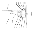
- FIGS 1A and 1B illustrate a sensor 100 in accordance with various aspects of the disclosure.
- the sensor 100 includes a housing 102 that covers and protects a sensing arrangement 110 (discussed in detail below).
- the housing 102 may include a first portion, or base, 104 and a second portion 106 fixedly coupled with one another.
- the housing 102 may further include a cover 108 removably coupleable with the second portion 106 of the housing 102.
- the first portion 104 may include a receiving arrangement 112 extending from a bottom 105 of the first portion 104 toward an interior of the housing 102.
- the receiving arrangement 112 may be configured to receive at least a portion of the sensing arrangement 110.
- the first portion 104 of housing 102 may be constructed of a material having a relatively high stiffness and strength so as to protect the sensor and circuitry housed therein.
- the material of the first portion 104 of housing 102 may be a metal, for example, aluminum or steel, or a composite. It may be desirable in some aspects to maximize the stiffness-to-weight ratio of the first portion 104 of housing 102 in order to effectively transmit vibration from the host structure to the sensor element without significantly affecting the vibration of the host structure.
- the cover 108 can be removed from the second portion 106 of the housing 102 to provide a user with access to an interior compartment of the second portion 106 of the housing 102, which can contain the battery 118. Thus, a user can remove and replace the battery 118 whenever needed.
- the first and second portions 104, 106 and the cover 108 may cooperate to define a weatherproof housing 102 of the sensor 100.
- the housing 102 may provide a sealed enclosure to prevent water, dust, oil, and the like from penetrating the housing 102.
- the sensor 100 can be used in a wide variety of harsh industrial environments and across a range of temperatures, humidity, and other conditions.
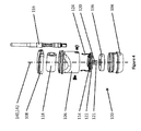
- the sensing arrangement 110 may include a sensing element 120 and a circuit board 122.
- the sensing element 120 may be an accelerometer such as, for example, an analog micro-electromechanical system (MEMS) accelerometer.
- the circuit board 122 may include a circuit arrangement 126 designed and configured to perform desired signal conditioning.
- the sensing arrangement 110, the radio 114, and the antenna 116 are electrically coupled with one another so that the sensor 100 can wirelessly transmit data, for example, acceleration data, to a remote receiver (not shown).
- the sensor 100 may include a pair of battery terminals 124 electronically coupled with and extending from the circuit board 122.
- the battery terminals 124 are contained by the housing 102 and configured to rigidly hold the battery 118 in electrical contact with the circuit board 122.
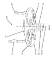
- the first portion 104 of the housing 102 may contain one or more magnets 136 at the bottom 105 of the first portion 104 of the housing 102.
- the magnets 136 may be of sufficient magnetic strength to couple the sensor 100 with the host structure 150, for example, a host structure made of a ferrous metal.
- the mounting arrangement 130 can include the magnets 136, alone or in combination with the threaded bore 132/threaded member 134.
- the sensor 100 may be coupled with the host structure 150 with an epoxy or any other adhesive of sufficient strength.
- the mounting arrangement can include an epoxy or any other adhesive.
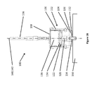
- the sensor 100 has a centerline 140 extending along a longitudinal dimension of the housing 102.
- the centerline 140 is substantially centered relative to a plane transverse to the longitudinal dimension. For example, if the housing assumes a generally cylindrical configuration, the centerline 140 would extend along a length of the housing and the transverse plane would extend in a radial direction.
- the circuit board 122 and the battery 118 are also substantially centered over the bottom 105 of the first portion 104 of the housing 102 relative to the centerline 140.
- the first portion 104 of the housing 102 may include a shoulder 128 on which the circuit board 122 may rest. If the circuit board 122 is configured to rest on the shoulder 128 about the periphery of the housing 102, the circuit board 122 would be centered about the centerline 140.
- the battery terminals 124 may can be arranged to extend from the circuit board 122 such that when the battery 118 is rigidly held by the terminals 124, the battery 118 extends in a direction transverse to and centered relative to the centerline 140.
- the battery 118 is cylindrical, a longitudinal and radial center of the battery 118 is substantially centered on the centerline 140. Although such a cylindrical battery would not be symmetrical for 360° in the transverse dimension, the battery's center of mass would be located along the centerline 140 of the sensor 100.
- the sensing element 120 has a main axis 142, which is aligned substantially along the centerline 140 of the sensor 100.
- the sensing element 120 may be substantially planar and extends in the longitudinal dimension of the sensor 100. It should be appreciated that the arrangement of the sensing element 120 in the longitudinal dimension may provide more accurate and/or more consistent measurements of vibration of the host structure 150 because the sensing element 120 may provide more accurate and/or more consistent measurements in the plane of the sensing element 120, as opposed to out of the plane (e.g., if the planar sensing element 120 were to extend transverse to the centerline 140).
- the mounting of the sensor 100 to the host structure 150 and the balance of the sensor 100 determine the degree of accuracy and consistency of vibration data.
- Sensors according to the disclosure are designed with the mounting arrangement 130, the sensing element 120 and its main axis 142, and the overall center of mass of the sensor 100 all aligned along the centerline 140 of the sensor 100. Because the center of mass and the measurement point (i.e., the sensing element 120) are centered directly over the center of the mounting arrangement 130, the sensor 100 is prevented from having a tendency to rock laterally when experiencing vertical vibration, or experience other motion which would influence and reduce the accuracy of the vibration measurement.
- the radio 114 may be constructed as its own circuit board separate from the circuit board 122. The radio 114 can then be attached to various different sensors.
- the connection between the two boards can be achieved using land grid array (LGA) soldering rather than using any type of connector, since a connector would add size and cost and possibly fatigue and fail over time due to prolonged vibration.
- LGA assembly process provides a common, compact interface that can be utilized across a variety of sensors, thereby allowing changes to either the radio or the sensor circuit without the requirement of changing both.
- the senor 100 it may be desirable to make the sensor 100 as compact as possible, while having the overall center of mass of the sensor 100 aligned with a center of the mounting arrangement 130 and the sensing element 120 and its main axis 142.
- the sensing element 120 may be disposed on a board 121 oriented in a vertical plane, whereas the remainder, for example, a majority, of the sensing arrangement (e.g., the circuit board 122) and the radio 114 may be in a horizontal plane.
- the battery 118 which is a major contributor to the overall weight of the sensor 100, can be rigidly held by the terminals 124 above the circuit board 122 and the radio 114 at a position where the mass of the battery 118 is substantially centered relative to the centerline 140 and easily accessible by a removing the cover 108 from the second portion 103 of the housing 102.
- the potting can also rigidly maintain the internal magnet 136 in place and seal the bottom 105 of the first portion 104 of the sensor 100.
- the potting also encapsulates the sensing element 120, preventing contamination or damage from foreign matter and also preventing the sensor from exchanging gases through its housing, which may cause the sensor's accuracy to slowly degrade over long periods of time.
- the two circuit boards 121, 122 can be connected by a right angle connector.
- right angle connectors can be more expensive, larger, and more likely to fail than a flex connector, thereby potentially leading to a larger profile sensor with lower reliability. Placing both of the two circuit boards 121, 122 in a vertical orientation would lead to an even larger profile sensor as the battery would have to be displaced to a new area.
- the sensing element may comprise a digital MEMS accelerometer, which includes analog-to-digital conversion and signal conditioning in one IC chip.
- the digital accelerometer would be wired directly to a master controller through a communication BUS such as SPI or I2C.
- the circuit arrangement may include a master controller, such that the radio, the antenna, and the master controller comprise a wireless communication part of the sensor 100.
- the wireless communication part supplies data from the master controller to a remote wireless data aggregator (not shown). It may also serve as a means to maintain remote control and monitoring of the sensor node.
- MEMS accelerometers can be implemented to exhibit ultra-low power operation however the current commercially available MEMS accelerometers have limited bandwidth and noise floor which may preclude uses for applications requiring very high fidelity measurement. If a MEMS accelerometer performance is acceptable, then the accelerometer can be mounted to the circuit board, which is centered over the base.
- Piezoelectric accelerometers are capable of performing wide bandwidth and high resolution measurements. However, acceleration measurement using traditional piezoelectric accelerometers can consume significant power and therefore the particular implementation of the sensor is important.
- Integrated charge amplifiers are generally used with piezoelectric accelerometers because they enable use of long wire connections between the accelerometer and a data acquisition system that are protected to some degree from external EMI.
- wireless accelerometers the wire length from the piezoelectric element to the microprocessor analog to digital converter can be short and therefore the integrated charge amplifier can be eliminated or redesigned for low power operation. To shorten the wire length a piezoelectric accelerometer and the circuit should be located adjacent to one another.
- an accelerometer 120 such as PCB Piezotronics' T-05 Embedded accelerometer can be soldered directly to the circuit board 121.
- Simple signal conditioning including filters and amplifiers can be implemented on the circuit board 122 instead of using a piezoelectric accelerometer integrated charge amplifier.
- the wireless vibration sensor 100 may be temporarily or permanently mounted to a particular point on a host machine 150.
- the sensor 150 then periodically or continuously measures the vibration of the machine at that point and wirelessly transmits the data to a receiver at a central location so that the data can be monitored.
- Monitoring can be done solely by an operator, or software alarms can be set up to alert an operator in the event of exceedances or fault conditions. In this manner, a large number of monitoring points can all be monitored from one central location without the need to repeatedly visit each machine in a facility and manually measure its vibration in a walk-around fashion, and without the need to run wires to each machine.
Landscapes
- Physics & Mathematics (AREA)
- General Physics & Mathematics (AREA)
- Engineering & Computer Science (AREA)
- Computer Hardware Design (AREA)
- Microelectronics & Electronic Packaging (AREA)
- Arrangements For Transmission Of Measured Signals (AREA)
Applications Claiming Priority (1)
| Application Number | Priority Date | Filing Date | Title |
|---|---|---|---|
| US14/192,025 US9453854B2 (en) | 2014-02-27 | 2014-02-27 | Vibration sensor |
Publications (2)
| Publication Number | Publication Date |
|---|---|
| EP2913643A2 true EP2913643A2 (de) | 2015-09-02 |
| EP2913643A3 EP2913643A3 (de) | 2016-05-25 |
Family
ID=52669437
Family Applications (1)
| Application Number | Title | Priority Date | Filing Date |
|---|---|---|---|
| EP15156594.2A Withdrawn EP2913643A3 (de) | 2014-02-27 | 2015-02-25 | Vibrationssensor |
Country Status (4)
| Country | Link |
|---|---|
| US (1) | US9453854B2 (de) |
| EP (1) | EP2913643A3 (de) |
| AU (1) | AU2015200979A1 (de) |
| CA (1) | CA2883116A1 (de) |
Cited By (2)
| Publication number | Priority date | Publication date | Assignee | Title |
|---|---|---|---|---|
| WO2022171799A1 (en) * | 2021-02-12 | 2022-08-18 | Analog Devices International Unlimited Company | Integrated device package |
| EP4073767A4 (de) * | 2019-12-10 | 2024-01-31 | Barnes Group Inc. | Drahtloser sensor mit bakentechnik |
Families Citing this family (13)
| Publication number | Priority date | Publication date | Assignee | Title |
|---|---|---|---|---|
| US9419331B1 (en) * | 2013-12-27 | 2016-08-16 | Kcf Technologies, Inc | Flexible antenna with weatherproof protection system and method of weather proofing and adding a flexible feature to existing antennas |
| EP2940358B1 (de) * | 2014-04-30 | 2019-03-13 | Faist Componenti S.p.A. | Vorrichtung zur erzeugung eines mit einem beweglichem stab eines pneumatischen aktuators assoziierbaren magnetfelds und verfahren zur herstellung der vorrichtung |
| US10236920B2 (en) | 2015-12-15 | 2019-03-19 | Battelle Memorial Institute | Signal transmitter and methods for transmitting signals from animals |
| US11278004B2 (en) | 2015-12-15 | 2022-03-22 | Battelle Memorial Institute | Transmitters for animals and methods for transmitting from animals |
| US10531639B2 (en) | 2016-08-25 | 2020-01-14 | Battelle Memorial Institute | Systems and methods for monitoring organisms within an aquatic environment |
| US10697809B1 (en) * | 2017-03-31 | 2020-06-30 | Petasense Inc. | Sensor housing with mounting plate and alignment indication |
| US10794150B2 (en) | 2017-06-16 | 2020-10-06 | Forum Us, Inc. | Predicting and optimizing drilling equipment operating life using condition based maintenance |
| DE102018216166B3 (de) | 2018-09-21 | 2019-10-24 | Siemens Aktiengesellschaft | Messaufnehmer |
| US11533818B2 (en) * | 2019-03-12 | 2022-12-20 | Battelle Memorial Institute | Sensor assemblies and methods for emulating interaction of entities within water systems |
| US11226229B2 (en) | 2019-11-06 | 2022-01-18 | Computational Systems, Inc. | Vibration sensor mounting structure |
| EP3835792B1 (de) * | 2019-12-11 | 2024-06-12 | Treon Oy | Beschleunigungsaufnehmer und verfahren zur messung von beschleunigungsdaten |
| US20240280437A1 (en) * | 2023-02-20 | 2024-08-22 | Resonance Systems, Inc. | Valve event monitoring sensor |
| WO2025170994A1 (en) * | 2024-02-09 | 2025-08-14 | Industrial Consulting Automation Research Engineering SRL | Method and apparatus for automated production of piezoelectric accelerometers |
Family Cites Families (12)
| Publication number | Priority date | Publication date | Assignee | Title |
|---|---|---|---|---|
| US6122340A (en) | 1998-10-01 | 2000-09-19 | Personal Electronic Devices, Inc. | Detachable foot mount for electronic device |
| US6778100B2 (en) * | 2002-03-06 | 2004-08-17 | Automatika, Inc. | Conduit network system |
| US20060238330A1 (en) | 2004-11-02 | 2006-10-26 | Ihs Imonitoring Inc. | Adaptable wireless sensor |
| US7424403B2 (en) * | 2006-09-29 | 2008-09-09 | Csi Technology, Inc. | Low power vibration sensor and wireless transmitter system |
| US8217790B2 (en) * | 2009-05-26 | 2012-07-10 | Script Michael H | Portable motion detector and alarm system and method |
| DK2517473T3 (da) * | 2009-12-22 | 2013-07-01 | Abb As | Trådløs sensoranordning og fremgangsmåde til trådløs kommunikation af en affølt fysisk parameter |
| US8700353B2 (en) | 2010-05-27 | 2014-04-15 | Incheck Technologies, Inc. | MEMS accelerometer device |
| US8635916B1 (en) * | 2010-07-06 | 2014-01-28 | Jacob Loverich | Internal structural monitoring system |
| US20150015405A1 (en) | 2011-12-20 | 2015-01-15 | Aktiebolaget Skf | Warning device for monitoring a health status of a bearing mounted to a piece of rotating industrial machinery |
| EP2698609B1 (de) | 2012-08-13 | 2021-03-03 | Alcatel Lucent | Drahtlose Messvorrichtung und Verfahren |
| US20140182378A1 (en) * | 2012-12-31 | 2014-07-03 | Kcf Technologies, Inc. | Energy harvester powered accelerometer |
| US9921136B2 (en) * | 2014-08-05 | 2018-03-20 | 01dB-Metravib, Societe Par Actions Simplifee | Wireless collection and analysis of machine data |
-
2014
- 2014-02-27 US US14/192,025 patent/US9453854B2/en active Active
-
2015
- 2015-02-25 CA CA2883116A patent/CA2883116A1/en not_active Abandoned
- 2015-02-25 EP EP15156594.2A patent/EP2913643A3/de not_active Withdrawn
- 2015-02-26 AU AU2015200979A patent/AU2015200979A1/en not_active Abandoned
Non-Patent Citations (1)
| Title |
|---|
| None |
Cited By (3)
| Publication number | Priority date | Publication date | Assignee | Title |
|---|---|---|---|---|
| EP4073767A4 (de) * | 2019-12-10 | 2024-01-31 | Barnes Group Inc. | Drahtloser sensor mit bakentechnik |
| US12222408B2 (en) | 2019-12-10 | 2025-02-11 | Barnes Group Inc. | Wireless sensor |
| WO2022171799A1 (en) * | 2021-02-12 | 2022-08-18 | Analog Devices International Unlimited Company | Integrated device package |
Also Published As
| Publication number | Publication date |
|---|---|
| US9453854B2 (en) | 2016-09-27 |
| EP2913643A3 (de) | 2016-05-25 |
| US20150241463A1 (en) | 2015-08-27 |
| AU2015200979A1 (en) | 2015-09-10 |
| CA2883116A1 (en) | 2015-08-27 |
Similar Documents
| Publication | Publication Date | Title |
|---|---|---|
| US9453854B2 (en) | Vibration sensor | |
| US10302510B2 (en) | Wireless axial load cell and sensor assembly | |
| CN104252163B (zh) | 具有逻辑能力的电源模块 | |
| US8635916B1 (en) | Internal structural monitoring system | |
| US11993463B2 (en) | Conveyor idler monitoring apparatus, systems, and methods | |
| CN108226777B (zh) | 状态监测装置以及用于监测电机的方法 | |
| US8640545B2 (en) | Vibration sensor with mechanical isolation member | |
| JP2015215226A (ja) | 状態検出装置 | |
| CN115480520A (zh) | IoT传感器和用于监控工业设备的系统 | |
| US10324055B2 (en) | Process variable transmitter with terminal block moisture sensor | |
| US12058481B2 (en) | Hybrid modular wireless sensor | |
| CN112284355B (zh) | 一种无源压电传感器及监测系统 | |
| GB2527942A (en) | Monitoring device | |
| EP3847420B1 (de) | Hybrid modularer drahtloser sensor | |
| US20160125719A1 (en) | Rfid enabled machine condition indicator and associated system for monitoring a health status of a bearing | |
| KR101839429B1 (ko) | Uhf 절연열화와 진동 및 온습도 감시진단 기능을 구비한 ess용 파워컨디셔닝시스템 | |
| JP2005164315A (ja) | 設備診断システム及びポンプ又はモーターとシステム制御装置 | |
| KR20230096531A (ko) | IoT센서를 적용한 펌프 모니터링 및 자동제어 시스템 | |
| KR102629423B1 (ko) | 사물 인터넷 센서 및 이를 이용한 산업용 장비의 데이터 획득방법 | |
| CN217972102U (zh) | 一种电梯轿厢运行监测装置、系统及电梯 | |
| GB2550541A (en) | Monitoring device | |
| CN113358089A (zh) | 铁路隔声屏障状态检测装置、方法及系统 | |
| EP4186774B1 (de) | Kabelloses lagerüberwachungssystem mit mobilem messgerät für fahrzeuge, land- und industriemaschinen | |
| CN113884129A (zh) | 一种集成式加速度速度振动传感器 | |
| CN206960635U (zh) | 用于磁共振断层扫描仪的部件的记录系统和磁共振断层扫描仪的部件 |
Legal Events
| Date | Code | Title | Description |
|---|---|---|---|
| PUAI | Public reference made under article 153(3) epc to a published international application that has entered the european phase |
Free format text: ORIGINAL CODE: 0009012 |
|
| AK | Designated contracting states |
Kind code of ref document: A2 Designated state(s): AL AT BE BG CH CY CZ DE DK EE ES FI FR GB GR HR HU IE IS IT LI LT LU LV MC MK MT NL NO PL PT RO RS SE SI SK SM TR |
|
| AX | Request for extension of the european patent |
Extension state: BA ME |
|
| PUAL | Search report despatched |
Free format text: ORIGINAL CODE: 0009013 |
|
| AK | Designated contracting states |
Kind code of ref document: A3 Designated state(s): AL AT BE BG CH CY CZ DE DK EE ES FI FR GB GR HR HU IE IS IT LI LT LU LV MC MK MT NL NO PL PT RO RS SE SI SK SM TR |
|
| AX | Request for extension of the european patent |
Extension state: BA ME |
|
| RIC1 | Information provided on ipc code assigned before grant |
Ipc: G01H 1/00 20060101AFI20160420BHEP |
|
| STAA | Information on the status of an ep patent application or granted ep patent |
Free format text: STATUS: THE APPLICATION IS DEEMED TO BE WITHDRAWN |
|
| 18D | Application deemed to be withdrawn |
Effective date: 20161126 |