EP2913628A1 - Artillery projectile warhead fuse comprising a braking device acting in flight direction - Google Patents
Artillery projectile warhead fuse comprising a braking device acting in flight direction Download PDFInfo
- Publication number
- EP2913628A1 EP2913628A1 EP15152942.7A EP15152942A EP2913628A1 EP 2913628 A1 EP2913628 A1 EP 2913628A1 EP 15152942 A EP15152942 A EP 15152942A EP 2913628 A1 EP2913628 A1 EP 2913628A1
- Authority
- EP
- European Patent Office
- Prior art keywords
- flap
- rocket
- notch
- flaps
- projectile
- Prior art date
- Legal status (The legal status is an assumption and is not a legal conclusion. Google has not performed a legal analysis and makes no representation as to the accuracy of the status listed.)
- Granted
Links
- 230000000295 complement effect Effects 0.000 claims abstract description 5
- 238000005192 partition Methods 0.000 claims description 25
- 238000012423 maintenance Methods 0.000 claims description 3
- 238000007373 indentation Methods 0.000 abstract description 5
- 238000010304 firing Methods 0.000 description 6
- 230000000977 initiatory effect Effects 0.000 description 4
- 235000015842 Hesperis Nutrition 0.000 description 3
- 235000012633 Iberis amara Nutrition 0.000 description 3
- 239000007789 gas Substances 0.000 description 3
- 208000031968 Cadaver Diseases 0.000 description 2
- 229910000831 Steel Inorganic materials 0.000 description 2
- 240000008042 Zea mays Species 0.000 description 2
- 239000002360 explosive Substances 0.000 description 2
- 239000010959 steel Substances 0.000 description 2
- 230000001133 acceleration Effects 0.000 description 1
- XAGFODPZIPBFFR-UHFFFAOYSA-N aluminium Chemical compound [Al] XAGFODPZIPBFFR-UHFFFAOYSA-N 0.000 description 1
- 229910052782 aluminium Inorganic materials 0.000 description 1
- 230000000903 blocking effect Effects 0.000 description 1
- 238000005474 detonation Methods 0.000 description 1
- 239000006185 dispersion Substances 0.000 description 1
- 230000000694 effects Effects 0.000 description 1
- 238000005516 engineering process Methods 0.000 description 1
- 229910001234 light alloy Inorganic materials 0.000 description 1
- 239000000463 material Substances 0.000 description 1
- 239000000203 mixture Substances 0.000 description 1
- 230000037452 priming Effects 0.000 description 1
- 239000003380 propellant Substances 0.000 description 1
- 230000004044 response Effects 0.000 description 1
Images


Classifications
-
- F—MECHANICAL ENGINEERING; LIGHTING; HEATING; WEAPONS; BLASTING
- F42—AMMUNITION; BLASTING
- F42B—EXPLOSIVE CHARGES, e.g. FOR BLASTING, FIREWORKS, AMMUNITION
- F42B10/00—Means for influencing, e.g. improving, the aerodynamic properties of projectiles or missiles; Arrangements on projectiles or missiles for stabilising, steering, range-reducing, range-increasing or fall-retarding
- F42B10/32—Range-reducing or range-increasing arrangements; Fall-retarding means
- F42B10/48—Range-reducing, destabilising or braking arrangements, e.g. impact-braking arrangements; Fall-retarding means, e.g. balloons, rockets for braking or fall-retarding
- F42B10/50—Brake flaps, e.g. inflatable
Definitions
- the technical field of the invention is that of artillery projectile warhead rockets that incorporate a translational braking device to increase the aerodynamic drag of the projectile.
- Rockets with ogive braking can increase the accuracy of artillery fire by taking into account dispersions due to variations in the initial velocity of the projectile. In fact, it is then possible to point the weapon so as to fire farther than the target, a firing line measures the actual speed of the projectile at the exit of the barrel of the weapon and a braking command is then transmitted to the projectile so as to reduce its range and thus bring it to the desired point of impact.
- the flaps of the rocket described by the patent EP1045221 each comprise two closed grooves substantially parallel to a direction perpendicular to the axis of the rocket, each groove cooperating with a rod which is fixed relative to the rocket. Thus the flaps are translated radially.
- Each flap comprises a notch which partially surrounds an axial support of the rocket, each flap thus has a U-shape.
- This architecture makes it possible to obtain an increased mechanical resistance of the shutters to the aerodynamic forces while ensuring a symmetry of perfect deployment.
- the subject of the invention is an ogive rocket for a gyro-stabilized artillery projectile, a rocket incorporating a translational braking device comprising at least two radially deployable flaps on a trajectory so as to increase the aerodynamic drag of the projectile, each flap comprising at least two closed grooves substantially parallel to a direction perpendicular to the axis of the rocket, each groove cooperating with a rod which is fixed relative to a body of the rocket, grooves disposed on either side of a notch which is intended to allow the positioning of the flap in the folded position around a central part of the body of the rocket, rocket characterized in that the notch of each flap comprises end nozzles which are engaged in fingerprints of complementary shapes which are carried by a holding part connected to the rocket.
- the holding piece may comprise an internal medial portion which is engaged in the notch of a flap in the folded position, the middle portion which is extended by two wings, each wing having a cavity receiving one of the flaps of the flap.
- the holding part may comprise a circular outer profile which will extend the outer profile of the shutter.
- the rocket may comprise three regularly angularly distributed flaps, three rods also regularly distributed angularly guiding the various flaps, each rod also ensuring the maintenance of a holding part.
- each flap can be housed in a groove of the body of the rocket groove which is delimited by partitions or surfaces of the body which are parallel to each other.
- At least one partition has a clearance allowing the passage of a pin carried by a flap disposed on one side of said partition, pin which engages in a notch carried by another flap disposed of the other side of said partition.
- an artillery projectile 1 is provided at its rear portion with a belt 2 intended to take the stripes of a weapon tube (not shown) and to seal the propellant gases when firing the projectile .
- This projectile carries at its front part a rocket 3 according to the invention, rocket which is intended in a conventional manner and according to the type of projectile considered (explosive projectile or cargo projectile) to provide either the initiation of an explosive charge disposed inside the projectile, or the ignition of a gas-generating charge for ejecting a payload arranged inside the trajectory of the projectile.
- the rocket comprises an electronic control device 4 which causes the initiation of a pyrotechnic charge 5 (which is depending on the case a detonation relay or a gas generator).
- this rocket 3 also incorporates a device for braking in translation 6 enabling the radial deployment on the trajectory of braking flaps 7.
- the deployment of the flaps 7 is controlled by the electronic control device 4 in response to an order received. on trajectory via a receiver 8 or developed by the electronic control device 4 as a result of a pre-shooting program, or else that is modified in the first moments after firing to take into account the initial speed the projectile.
- the trajectory programming will be provided via the receiver 8 which may be radar technology.
- the figure 2 shows this rocket in more detail.
- the pyrotechnic charge 5 is disposed in a cup secured to the body and communicates through a priming channel 10 with an initiating component 11 (primer or igniter) with electrical release, which is itself connected to the electronic device order 4.
- the initiation component 11 is carried by a movable flap 12 of a safety and arming device (not shown).
- the body 13 of the rocket comprises at a front part three annular grooves 17a, 17b and 17c which are delimited by three parallel partitions 15a, 15b and 15c as well as by a rear annular bearing surface 16 of the body 13.
- the grooves extend radially to a central portion 14 of the substantially cylindrical body and which is traversed by the channel 10.
- the upper partition 15a receives an upper portion of the rocket enclosing the electronic device 4.
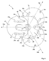
- the annular grooves 17a, 17b, 17c receive the braking device 6 which comprises three flaps 7.
- the braking device 6 which comprises three flaps 7.
- three flaps 7 of identical shapes are integral with the body 13. These flaps are marked 7a, 7b and 7c on figures 3 , 4 and 6 to distinguish them from each other.
- Each flap is capable of translating in a plane perpendicular to the axis 20 of the projectile. It is guided in its translation by two cylindrical rods 21 which are fixed (here only one rod 21b is visible). Each rod is disposed between the upper wall 15a and a hole 18 carried by the rear portion of the body 13. The rods 21 are all parallel to the axis 20 of the projectile and the rocket. They are forced into the holes 18.
- the figure 3 shows the distribution of the rods 21.
- Three rods 21a, 21b and 21c are provided and distributed angularly in a regular manner around the axis 20 of the rocket (equidistant from the axis 20 and with an angle of 120 ° between each position).
- Each rod 21 is cylindrical and cooperates with four coaxial holes drilled in the three partitions 15a to 15c and only in the body 13 (the latter hole is marked 18 in the figures).
- Each flap 7a, 7b and 7c comprises two closed grooves 22 and 23 generally parallel to a direction 24 perpendicular to the axis 20 of the projectile.
- the grooves 22 and 23 and the direction 24 are marked on the figures 2 and 3 by the designations 22a, 22b, 22c, 23a, 23b, 23c and 24a, 24b, 24c to distinguish the flaps and their structural and geometric elements relative to each other.
- the upper flap 7a has two grooves 22a, 23a parallel to a direction 24a.
- the median flap 7b has two grooves 22b, 23b parallel to a direction 24b.
- the lower flap 7c has two grooves 22c, 23c parallel to a direction 24c.
- these grooves each comprise a corrugation 37.
- this corrugation 37 shares each groove in two rectilinear aligned portions 38.1 and 38.2 which are separated by another rectilinear portion 38.3 parallel to the previous ones. Rounded portions connect the linear portions.
- the amplitude of the corrugation is about 2 mm and its length about 4 mm.
- Each groove cooperates with a rod 21 fixed relative to the projectile and more particularly each rod cooperates with two grooves of two adjacent flaps.
- Each flap 7 is held between two parallel surfaces or partitions delimiting a groove 17.
- the flap 7a is disposed in the groove 17a, between the upper partition 15a and the next partition 15b.
- the flap 7b is disposed in the groove 17b, between the partitions 15b and 15c.
- the flap 7c is disposed in the groove 17c between the partition 15c and the bearing surface 16 of the body 13.
- Such an arrangement of the shutters ensures the protection of the shutters and their mechanical resistance to the acceleration developed during firing of the projectile.
- a game of the order of a tenth of a millimeter is provided between each flap 7 and the groove 17 which receives it, as well as between the rods 21a, 21b and 21c and the grooves in order to allow the flaps to move from their position.
- the partitions separating the flaps are not shown.
- the central portion 14 of the body 13 of the rocket has been positioned in dotted lines.
- Each flap is made for example of sheet steel 2 mm thick and carries the two grooves 22, 23 for receiving the rods 21.
- the flaps may also be made of another material for example a light alloy (based on aluminum).
- each flap has an outer profile 25 covering an arc of a circle whose diameter is substantially equal to the outer diameter of the rocket 3.
- figure 5 thus shows a flap 7 alone.
- Each flap also has a notch 26 intended to allow the positioning of the flap around the central portion 14 of the body 13 of the rocket.
- the indentation 26 comprises a hemicylindrical portion 27 of the same diameter as that of the central portion 14 and coaxial with the axis 20 thereof (that is to say also to the axis of the rocket and the projectile ).
- the hemicylindrical portion 27 of the indentation is connected to two flat surfaces 28 and 29 which are parallel to the grooves 22, 23.
- a corrugation 40 is produced at the level of the flat surface 28 and a complementary recess 39 is arranged at the flat surface 29. These arrangements allow the lateral translation of the flap 7 with respect to the central portion 14 during the passage of the corrugations 37 by the stems 21.
- the corrugations of the grooves 22 and 23 make it possible to ensure braking of the opening movement of the flap 7. Indeed, when the rod 21 reaches the level of the corrugation 37, the clearance between the groove and the rod is distributed differently, the flap translates laterally with respect to the central portion 14, the groove rubs against the rod, thereby consuming energy and reducing the speed of movement of the shutter.
- the undulations thus constitute a means of slowing down the movement of deployment of the shutter. This reduces the impact of abutment of each flap against the guide rods at the end of the deployment movement, which increases the reliability of the device.
- the indented shape of the flaps 7 also allows to obtain a maximum flap surface for minimal space in the folded position.
- All flaps 7 here have the same structure and they comprise means that allow the locking of the shutters relative to each other in the folded position.
- each flap 7 carries a hole 30, this hole is intended to receive, at the level of the only first flap 7a, the rod 31 of a pyrotechnic piston 32 (see FIG. figure 2 ).
- This pyrotechnic piston is here a pyrotechnic retractor which is integral with the body 13 of the rocket. It comprises a gas generating composition which is electrically initiated by the control device 4 and which has the effect of causing the rod 31 to be pulled out of the hole 30.
- a pyrotechnic component is well known to those skilled in the art and it will not be described in more detail.
- the rod 31 of the retractor ensures the locking of the first flap 7a in the folded position.
- Each flap also carries a notch 33.
- the notch 33a of the first flap 7a is intended to cooperate with a first pin 34b carried by the second flap 7b to maintain the folded position thereof (see figure 3 ).
- the second flap 7b carries a second notch 33b (in dotted lines figure 3 ) which is intended to cooperate with a second pin 34c carried by the third flap 7c to maintain the folded position thereof.
- the pins 34b, 34c are housed in holes 47. Only the flaps 7b and 7c carry a pin, the flap 7a is devoid of it.
- the partitions 15b and 15c each comprise a clearance 48 which is delimited by two perpendicular planes. These clearances are visible at figure 3 with dots. A clearance is particularly visible at the figure 6 on which the partition 15b is shown.
- a single pyrotechnic piston 32 thus ensures the locking of all three components and prevents the deployment of these as a result of the centrifugal efforts exerted on them when firing the projectile.
- the holding pins are constituted by small cylindrical rods mounted in the holes 47 made on the flaps.
- the figure 3 shows the three flaps in their folded and locked position.
- the section of the rocket was made to remove the upper partition 15a. Only the first component 7a is completely visible. The three rods 21a, 21b and 21c are cut. The second component 7b is hidden by the partition 15b. The third part is also hidden.
- This figure shows how the different holding means cooperate with one another so as to ensure a locking of the three shutters.
- the pin 34c carried by the third flap 7c is positioned in the notch 33b of the second flap 7b (visible elements in dashed lines).
- the notch 33b is parallel to the direction 24b and is therefore cut by the direction of deployment 24c of the third component
- the third component can not open.
- each flap 7a, 7b and 7c comprises two end nozzles 41 which are each engaged in an impression 42 carried by a holding piece 43.
- These holding pieces 43 are all identical and are identified 43a, 43b and 43c on the figures 3 and 4 for distinguish the maintenance parts that are associated with each component.
- Each holding piece 43 is connected to the rocket 3 by a rod 21a, 21b or 21c. It is positioned, just like the shutter it blocks, in the annular groove 17a, 17b or 17c.
- Each holding piece 43 is constituted by a piece of steel sheet having substantially the same thickness as the flap considered.
- Each holding piece 43a, 43b, 43c has an internal medial portion 44 which is engaged in the notch 26 of the flap in the folded position. This median portion 44 is extended by two wings 45. Each wing 45 has a cavity 42 receiving one of the nozzles 41 of the flap in question.
- Each holding piece 43a, 43b, 43c finally has a circular outer profile 46 which extends the outer profile of the flap considered and closes the notch 26.
- the nozzles 41 have a trapezoidal profile.
- the wings 45 comprise imprints 42 which have a shape complementary to that of the nozzles 41.
- the trapezoidal profile allows an unlocking without excessive efforts during the deployment of the flap 7.
- the holding pieces 43a, 43b and 43c prevent the spacing of the nozzles 41 which would be caused by the action of the centrifugal forces. They thus prevent the opening of the indentation 26 which would cause jamming of the flap 7 with respect to its guide pins 21.
- the invention thus makes it possible to make the operation of the braking device 6 reliable.
- the invention it is also possible to implement the invention with a rocket whose braking device comprises only two flaps which are deployed in opposite directions to one another.
- the flaps will be further separated from each other by an intermediate partition secured to the body and which will receive a first flap on one side and a second flap on the other side.
- the flaps and the holding parts will then be housed in grooves delimited by the internal partition and by surfaces or surfaces of the rocket body which are parallel to this intermediate partition.
- the guide rods 21 will then be integral with this intermediate partition which will also carry the two holding pieces.
Abstract
L'invention a pour objet une fusée d'ogive pour un projectile d'artillerie gyrostabilisé, fusée incorporant un dispositif (6) de freinage en translation comprenant au moins deux volets (7a,7b,7c) déployables radialement sur trajectoire de façon à accroître la traînée aérodynamique du projectile. Chaque volet comporte au moins deux rainures (22,23) fermées coopérant chacune avec une tige (21a,21b,21c) qui est fixe par rapport à un corps de la fusée, rainures disposées de part et d'autre d'une échancrure (26) qui est destinée à permettre le positionnement du volet en position repliée autour d'une partie centrale (14) du corps. Cette fusée est caractérisée en ce que l'échancrure (26) de chaque volet (7a,7b,7c) comporte des becs d'extrémité (41) qui sont engagés dans des empreintes (42) de formes complémentaires qui sont portées par une pièce de maintien (43a,43b,43c) liée à la fusée (3).The invention relates to an ogive rocket for a gyro-stabilized artillery projectile, a rocket incorporating a device (6) for translational braking comprising at least two flaps (7a, 7b, 7c) deployable radially on a trajectory so as to increase the aerodynamic drag of the projectile. Each flap comprises at least two closed grooves (22,23) each cooperating with a rod (21a, 21b, 21c) which is fixed relative to a body of the rocket, grooves disposed on either side of a notch ( 26) which is intended to allow positioning of the flap in the folded position around a central portion (14) of the body. This rocket is characterized in that the indentation (26) of each flap (7a, 7b, 7c) comprises end tips (41) which are engaged in indentations (42) of complementary shapes which are carried by a part holding device (43a, 43b, 43c) connected to the rocket (3).
Description
Le domaine technique de l'invention est celui des fusées d'ogive pour projectile d'artillerie qui incorporent un dispositif de freinage en translation permettant d'accroître la traînée aérodynamique du projectile.The technical field of the invention is that of artillery projectile warhead rockets that incorporate a translational braking device to increase the aerodynamic drag of the projectile.
On connaît par le brevet
Les fusées à freinage d'ogive permettent d'accroître la précision des tirs d'artillerie en permettant de tenir compte des dispersions dues aux variations de la vitesse initiale du projectile. En effet, il est possible alors de pointer l'arme de façon à tirer plus loin que la cible visée, une conduite de tir mesure la vitesse réelle du projectile à la sortie du tube de l'arme et un ordre de freinage est ensuite transmis au projectile de façon à réduire sa portée et à l'amener ainsi au point d'impact souhaité.Rockets with ogive braking can increase the accuracy of artillery fire by taking into account dispersions due to variations in the initial velocity of the projectile. In fact, it is then possible to point the weapon so as to fire farther than the target, a firing line measures the actual speed of the projectile at the exit of the barrel of the weapon and a braking command is then transmitted to the projectile so as to reduce its range and thus bring it to the desired point of impact.
Les volets de la fusée décrite par le brevet
Cette architecture permet d'obtenir une résistance mécanique accrue des volets aux efforts aérodynamiques tout en assurant une symétrie de déploiement parfaite.This architecture makes it possible to obtain an increased mechanical resistance of the shutters to the aerodynamic forces while ensuring a symmetry of perfect deployment.
On a cependant pu observer que, à cause des efforts centrifuges subis lors du tir, les volets en forme de U étaient sujets à une déformation au niveau de l'échancrure (ouverture du U). Cette déformation, combinée aux jeux fonctionnels entre volets et tiges de guidage, conduit à des blocages ou coincements des volets qui nuisent à la symétrie du déploiement.However, it was observed that, due to the centrifugal forces experienced during firing, the U-shaped flaps were subject to deformation at the notch (opening of the U). This distortion, combined with the games functional shutters and guide rods, leads to blockages or jamming flaps that hinder the symmetry of the deployment.
C'est le but de l'invention que de proposer une architecture de volet permettant d'une façon simple de pallier un tel inconvénient.It is the object of the invention to provide a shutter architecture allowing a simple way to overcome such a disadvantage.
Ainsi l'invention a pour objet une fusée d'ogive pour un projectile d'artillerie gyrostabilisé, fusée incorporant un dispositif de freinage en translation comprenant au moins deux volets déployables radialement sur trajectoire de façon à accroître la traînée aérodynamique du projectile, chaque volet comportant au moins deux rainures fermées sensiblement parallèles à une direction perpendiculaire à l'axe de la fusée, chaque rainure coopérant avec une tige qui est fixe par rapport à un corps de la fusée, rainures disposées de part et d'autre d'une échancrure qui est destinée à permettre le positionnement du volet en position repliée autour d'une partie centrale du corps de la fusée, fusée caractérisée en ce que l'échancrure de chaque volet comporte des becs d'extrémité qui sont engagés dans des empreintes de formes complémentaires qui sont portées par une pièce de maintien liée à la fusée.Thus, the subject of the invention is an ogive rocket for a gyro-stabilized artillery projectile, a rocket incorporating a translational braking device comprising at least two radially deployable flaps on a trajectory so as to increase the aerodynamic drag of the projectile, each flap comprising at least two closed grooves substantially parallel to a direction perpendicular to the axis of the rocket, each groove cooperating with a rod which is fixed relative to a body of the rocket, grooves disposed on either side of a notch which is intended to allow the positioning of the flap in the folded position around a central part of the body of the rocket, rocket characterized in that the notch of each flap comprises end nozzles which are engaged in fingerprints of complementary shapes which are carried by a holding part connected to the rocket.
La pièce de maintien peut comporter une partie médiane interne qui est engagée dans l'échancrure d'un volet en position repliée, partie médiane qui est prolongée par deux ailes, chaque aile comportant une empreinte recevant un des becs du volet.The holding piece may comprise an internal medial portion which is engaged in the notch of a flap in the folded position, the middle portion which is extended by two wings, each wing having a cavity receiving one of the flaps of the flap.
La pièce de maintien pourra comporter un profil externe circulaire qui prolongera le profil externe du volet.The holding part may comprise a circular outer profile which will extend the outer profile of the shutter.
La fusée pourra comporter trois volets régulièrement répartis angulairement, trois tiges également régulièrement réparties angulairement assurant le guidage des différents volets, chaque tige assurant également le maintien d'une pièce de maintien.The rocket may comprise three regularly angularly distributed flaps, three rods also regularly distributed angularly guiding the various flaps, each rod also ensuring the maintenance of a holding part.
Avantageusement, chaque volet peut se loger dans un sillon du corps de la fusée, sillon qui est délimité par des cloisons ou surfaces du corps qui sont parallèles les unes aux autres.Advantageously, each flap can be housed in a groove of the body of the rocket groove which is delimited by partitions or surfaces of the body which are parallel to each other.
Selon une autre caractéristique, au moins une cloison comporte un dégagement permettant le passage d'un pion porté par un volet disposé d'un côté de ladite cloison, pion qui s'engage dans une encoche portée par un autre volet disposé de l'autre côté de ladite cloison.According to another feature, at least one partition has a clearance allowing the passage of a pin carried by a flap disposed on one side of said partition, pin which engages in a notch carried by another flap disposed of the other side of said partition.
L'invention sera mieux comprise à la lecture de la description qui va suivre de modes particuliers de réalisation, description faite en référence aux dessins annexés et dans lesquels :
- La
figure 1 montre schématiquement un projectile équipé d'une fusée selon l'invention. - La
figure 2 représente en coupe longitudinale partielle une fusée de projectile selon l'invention. - La
figure 3 est une vue en coupe du dispositif de freinage de la fusée, représenté en position repliée, coupe suivant le plan AA repéré à lafigure 2 . - La
figure 4 est une vue analogue à lafigure 3 mais le dispositif de freinage est en position dépliée et le corps de fusée n'est pas représenté. - La
figure 5 est une vue montrant un volet de freinage seul ainsi que la pièce de maintien associée. - La
figure 6 est une vue analogue à lafigure 4 mais avec le corps de fusée visible.
- The
figure 1 schematically shows a projectile equipped with a rocket according to the invention. - The
figure 2 represents in partial longitudinal section a projectile rocket according to the invention. - The
figure 3 is a sectional view of the rocket braking device, shown in the folded position, section along the plane AA marked at thefigure 2 . - The
figure 4 is a view similar to thefigure 3 but the braking device is in the unfolded position and the rocket body is not shown. - The
figure 5 is a view showing a single braking shutter and the associated holding part. - The
figure 6 is a view similar to thefigure 4 but with the visible rocket body.
En se reportant à la
A cet effet la fusée comporte un dispositif électronique de commande 4 qui provoque l'initiation d'une charge pyrotechnique 5 (qui est suivant le cas un relais de détonation ou un générateur de gaz).For this purpose the rocket comprises an
Conformément à l'invention, cette fusée 3 incorpore également un dispositif de freinage en translation 6 permettant le déploiement radial sur trajectoire de volets de freinage 7. Le déploiement des volets 7 est commandé par le dispositif électronique de commande 4 en réponse à un ordre reçu sur trajectoire par l'intermédiaire d'un récepteur 8 ou bien élaboré par le dispositif électronique de commande 4 comme suite à une programmation préalable au tir, ou bien encore qui est modifiée dans les premiers instants suivant le tir pour tenir compte de la vitesse initiale réelle du projectile.In accordance with the invention, this
La programmation sur trajectoire sera assurée par l'intermédiaire du récepteur 8 qui pourra être de technologie radar.The trajectory programming will be provided via the
La
Elle a une forme générale et un encombrement analogue à celui des fusées d'artillerie classiques. Elle comporte un corps 13 sur lequel est réalisé un filetage 9 destiné à permettre sa solidarisation avec le projectile. La charge pyrotechnique 5 est disposée dans un godet solidaire du corps et elle communique au travers d'un canal d'amorçage 10 avec un composant d'initiation 11 (amorce ou inflammateur) à déclenchement électrique, qui est lui-même relié au dispositif électronique de commande 4.It has a general shape and a footprint similar to that of conventional artillery rockets. It comprises a
D'une façon classique et qui n'est pas décrite ni représentée en détails, le composant d'initiation 11 est porté par un volet mobile 12 d'un dispositif de sécurité et d'armement (non représenté).In a conventional manner and which is not described or shown in detail, the
Le corps 13 de la fusée comporte au niveau d'une partie avant trois sillons annulaires 17a, 17b et 17c qui sont délimités par trois cloisons parallèles 15a, 15b et 15c ainsi que par une portée annulaire arrière 16 du corps 13.The
Les sillons s'étendent radialement jusqu'à une partie centrale 14 du corps sensiblement cylindrique et qui est traversée par le canal 10.The grooves extend radially to a
La cloison supérieure 15a reçoit une portion supérieure de la fusée renfermant le dispositif électronique 4.The
Les sillons annulaires 17a,17b,17c reçoivent le dispositif de freinage 6 qui comprend trois volets 7. Conformément à ce mode de réalisation de l'invention, trois volets 7 de formes identiques sont solidaires du corps 13. Ces volets sont repérés 7a, 7b et 7c sur les
Chaque volet est susceptible de se translater dans un plan perpendiculaire à l'axe 20 du projectile. Il est guidé dans sa translation par deux tiges cylindriques 21 qui sont fixes (ici une seule tige 21b est visible). Chaque tige est disposée entre la cloison supérieure 15a et un trou 18 porté par la partie arrière du corps 13. Les tiges 21 sont toutes parallèles à l'axe 20 du projectile et de la fusée. Elles sont emmanchées à force dans les trous 18.Each flap is capable of translating in a plane perpendicular to the
La
Chaque tige 21 est cylindrique et coopère avec quatre trous coaxiaux percés dans les trois cloisons 15a à 15c ainsi que dans le corps 13 (ce dernier trou est repéré 18 sur les figures).Each rod 21 is cylindrical and cooperates with four coaxial holes drilled in the three
Chaque volet 7a, 7b et 7c comporte deux rainures fermées 22 et 23 globalement parallèles à une direction 24 perpendiculaire à l'axe 20 du projectile. Les rainures 22 et 23 et la direction 24 sont repérées sur les
Le volet supérieur 7a comporte deux rainures 22a,23a parallèles à une direction 24a.The
Le volet médian 7b comporte deux rainures 22b,23b parallèles à une direction 24b.The
Le volet inférieur 7c comporte deux rainures 22c,23c parallèles à une direction 24c.The
Les trois directions 24a, 24b et 24c, coupent l'axe 20 de la fusée, elles sont perpendiculaires à cet axe et forment entre elles des angles de 120°.The three
Comme décrit par le brevet
Chaque rainure coopère avec une tige 21 fixe par rapport au projectile et plus particulièrement chaque tige coopère avec deux rainures de deux volets adjacents.Each groove cooperates with a rod 21 fixed relative to the projectile and more particularly each rod cooperates with two grooves of two adjacent flaps.
Ainsi la tige 21a assure le guidage de la rainure 23a du volet 7a et de la rainure 22b du volet 7b.Thus the
La tige 21b assure le guidage de la rainure 23b du volet 7b et de la rainure 22c du volet 7c.The
Enfin, la tige 21c assure le guidage de la rainure 23c du volet 7c et de la rainure 22a du volet 7a.Finally, the
Chaque volet 7 est maintenu entre deux surfaces ou cloisons parallèles délimitant un sillon 17. Ainsi le volet 7a est disposé dans le sillon 17a, entre la cloison supérieure 15a et la cloison suivante 15b. Le volet 7b est disposé dans le sillon 17b, entre les cloisons 15b et 15c. Le volet 7c est disposé dans le sillon 17c entre la cloison 15c et la portée 16 du corps 13.Each
Une telle disposition des volets assure la protection des volets et leur tenue mécanique à l'accélération développée lors du tir du projectile.Such an arrangement of the shutters ensures the protection of the shutters and their mechanical resistance to the acceleration developed during firing of the projectile.
Un jeu de l'ordre du dixième de millimètre est prévu, entre chaque volet 7 et le sillon 17 qui le reçoit, ainsi qu'entre les tiges 21a, 21b et 21c et les rainures afin d'autoriser le déplacement des volets de leur position de stockage représentée à la
Chaque volet est réalisé par exemple en tôle d'acier de 2 mm d'épaisseur et porte les deux rainures 22, 23 destinées à recevoir les tiges 21. Les volets pourront également être réalisés en un autre matériau par exemple un alliage léger (à base d'aluminium).Each flap is made for example of
Comme cela est décrit dans le brevet
Chaque volet présente également une échancrure 26 destinée à permettre le positionnement du volet autour de la partie centrale 14 du corps 13 de la fusée. A cet effet l'échancrure 26 comporte une portion hémicylindrique 27 de même diamètre que celui de la partie centrale 14 et coaxiale à l'axe 20 de celle-ci (c'est à dire aussi à l'axe de la fusée et du projectile). La portion hémicylindrique 27 de l'échancrure se raccorde à deux surfaces plane 28 et 29 qui sont parallèles aux rainures 22, 23.Each flap also has a
Une ondulation 40 est réalisée au niveau de la surface plane 28 et un creux complémentaire 39 est aménagé au niveau de la surface plane 29. Ces dispositions autorisent la translation latérale du volet 7 par rapport à la partie centrale 14 lors du passage des ondulations 37 par les tiges 21.A
Comme décrit par le brevet
La forme échancrée des volets 7 permet par ailleurs d'obtenir une surface de volet maximale pour un encombrement minimal en position repliée.The indented shape of the
Tous les volets 7 ont ici la même structure et ils comportent des moyens qui permettent les verrouillages des volets les uns par rapport aux autres en position repliée.All
Ainsi chaque volet 7 porte un trou 30, ce trou est destiné à recevoir, au niveau du seul premier volet 7a, la tige 31 d'un piston pyrotechnique 32 (voir
Ce piston pyrotechnique est ici un rétracteur pyrotechnique qui est solidaire du corps 13 de la fusée. Il comprend une composition génératrice de gaz qui est initiée électriquement par le dispositif de commande 4 et qui a pour effet de provoquer le retrait de la tige 31 hors du trou 30. Un tel composant pyrotechnique est bien connu de l'Homme du Métier et il ne sera pas décrit plus en détails.This pyrotechnic piston is here a pyrotechnic retractor which is integral with the
La tige 31 du rétracteur assure le verrouillage du premier volet 7a en position repliée.The
Chaque volet porte aussi une encoche 33. L'encoche 33a du premier volet 7a est destinée à coopérer avec un premier pion 34b porté par le deuxième volet 7b pour assurer le maintien en position repliée de celui-ci (voir
D'une façon analogue, le deuxième volet 7b porte une deuxième encoche 33b (en pointillés
Afin de permettre aux pions 34b et 34c de se positionner dans les encoches 33a et 33b des volets 7a et 7b, les cloisons 15b et 15c comportent chacune un dégagement 48 qui est délimité par deux plans perpendiculaires. Ces dégagements sont visibles à la
Les pions de maintien sont constitués par des petites tiges cylindriques montées dans les trous 47 réalisés sur les volets.The holding pins are constituted by small cylindrical rods mounted in the
La
La coupe de la fusée a été réalisée de façon à retirer la cloison supérieure 15a. Seul le premier volet 7a est complètement visible. Les trois tiges 21a,21b et 21c sont coupées. Le deuxième volet 7b est caché par la cloison 15b. Le troisième volet est lui aussi caché.The section of the rocket was made to remove the
Cette figure montre comment coopèrent entre eux les différents moyens de maintien de façon à assurer un verrouillage des trois volets.This figure shows how the different holding means cooperate with one another so as to ensure a locking of the three shutters.
On voit ainsi que, lorsque le premier volet 7a se trouve immobilisé par la tige 31 du piston pyrotechnique introduite dans le trou 30, le pion 34b du deuxième volet est positionné dans l'encoche 33a du premier volet 7a, encoche 33a qui est parallèle à la direction 24a et qui est donc coupée par la direction 24b de déploiement du deuxième volet. Le deuxième volet ne peut donc pas se déployer.It can thus be seen that, when the
D'une façon analogue, le pion 34c porté par le troisième volet 7c est positionné dans l'encoche 33b du deuxième volet 7b (éléments visibles en pointillés). L'encoche 33b est parallèle à la direction 24b et qui est donc coupée par la direction 24c de déploiement du troisième volet Le troisième volet ne peut donc pas s'ouvrir.In a similar way, the
Conformément à l'invention, l'échancrure 26 de chaque volet 7a,7b et 7c comporte deux becs d'extrémité 41 qui sont chacun engagés dans une empreinte 42 portée par une pièce de maintien 43. Ces pièces de maintien 43 sont toutes identiques et sont repérées 43a, 43b et 43c sur les
Chaque pièce de maintien 43 est liée à la fusée 3 par une tige 21a, 21b ou 21c. Elle est positionnée, tout comme le volet qu'elle bloque, dans le sillon annulaire 17a, 17b ou 17c.Each holding
Chaque pièce de maintien 43 est constituée par une pièce de tôle d'acier ayant sensiblement la même épaisseur que le volet considéré.Each holding
Chaque pièce de maintien 43a,43b,43c comporte une partie médiane interne 44 qui est engagée dans l'échancrure 26 du volet en position repliée. Cette partie médiane 44 est prolongée par deux ailes 45. Chaque aile 45 comporte une empreinte 42 recevant un des becs 41 du volet considéré.Each holding
Chaque pièce de maintien 43a, 43b, 43c comporte enfin un profil externe circulaire 46 qui prolonge le profil externe du volet considéré et ferme l'échancrure 26.Each holding
On voit sur les
Le profil trapézoïdal permet un déverrouillage sans efforts excessifs lors du déploiement du volet 7.The trapezoidal profile allows an unlocking without excessive efforts during the deployment of the
Lorsque les volets sont en position repliée (
L'invention permet ainsi de fiabiliser le fonctionnement du dispositif de freinage 6.The invention thus makes it possible to make the operation of the
Il n'est pas nécessaire d'immobiliser en rotation la pièce de maintien par rapport à sa tige 21. En position repliée, le volet 7 empêche la rotation de la pièce de maintien 43 qui lui est associée. En position déployée, les mouvements de pivotement limités de la pièce de maintien 43 dans le sillon 17 n'ont pas d'importance.It is not necessary to immobilize in rotation the holding member relative to its rod 21. In the folded position, the
Il est possible de mettre en oeuvre l'invention avec des volets 7 dont les rainures 22,23 sont droites et ne comportent pas d'ondulations 37. De telles rainures sont décrites par le brevet
Il est également possible de mettre en oeuvre l'invention avec une fusée dont le dispositif de freinage ne comporte que deux volets qui se déploient suivant des directions opposées l'une à l'autre. Dans ce cas les volets seront encore séparés l'un de l'autre par une cloison intermédiaire solidaire du corps et qui recevra un premier volet sur une face et un deuxième volet sur l'autre face. Les volets et les pièces de maintien seront alors logées dans des sillons délimités par la cloison interne et par des surfaces ou portées du corps de fusée qui sont parallèles à cette cloison intermédiaire. Les tiges de guidage 21 seront alors toutes solidaires de cette cloison intermédiaire qui portera aussi les deux pièces de maintien.It is also possible to implement the invention with a rocket whose braking device comprises only two flaps which are deployed in opposite directions to one another. In this case the flaps will be further separated from each other by an intermediate partition secured to the body and which will receive a first flap on one side and a second flap on the other side. The flaps and the holding parts will then be housed in grooves delimited by the internal partition and by surfaces or surfaces of the rocket body which are parallel to this intermediate partition. The guide rods 21 will then be integral with this intermediate partition which will also carry the two holding pieces.
Claims (6)
Priority Applications (1)
| Application Number | Priority Date | Filing Date | Title |
|---|---|---|---|
| PL15152942T PL2913628T3 (en) | 2014-02-27 | 2015-01-28 | Artillery projectile warhead fuse comprising a braking device acting in flight direction |
Applications Claiming Priority (1)
| Application Number | Priority Date | Filing Date | Title |
|---|---|---|---|
| FR1400529A FR3017943B1 (en) | 2014-02-27 | 2014-02-27 | ARTILLERY PROJECTILE OGIVE SHAFT HAVING A BRAKING DEVICE IN TRANSLATION |
Publications (2)
| Publication Number | Publication Date |
|---|---|
| EP2913628A1 true EP2913628A1 (en) | 2015-09-02 |
| EP2913628B1 EP2913628B1 (en) | 2017-01-11 |
Family
ID=51225578
Family Applications (1)
| Application Number | Title | Priority Date | Filing Date |
|---|---|---|---|
| EP15152942.7A Active EP2913628B1 (en) | 2014-02-27 | 2015-01-28 | Artillery projectile warhead fuse comprising a braking device acting in flight direction |
Country Status (4)
| Country | Link |
|---|---|
| EP (1) | EP2913628B1 (en) |
| ES (1) | ES2618063T3 (en) |
| FR (1) | FR3017943B1 (en) |
| PL (1) | PL2913628T3 (en) |
Cited By (1)
| Publication number | Priority date | Publication date | Assignee | Title |
|---|---|---|---|---|
| WO2020091646A1 (en) * | 2018-10-30 | 2020-05-07 | Bae Systems Bofors Ab | Brake assembly, detonator and projectile |
Citations (3)
| Publication number | Priority date | Publication date | Assignee | Title |
|---|---|---|---|---|
| WO1998001719A1 (en) * | 1996-07-05 | 1998-01-15 | The Secretary Of State For Defence | Means for increasing the drag on a munition |
| EP1006335A1 (en) * | 1998-11-30 | 2000-06-07 | Giat Industries | Device for reducing the velocity of a projectile on its trajectory |
| EP1045221A1 (en) | 1999-04-16 | 2000-10-18 | Giat Industries | Aerodynamic brake for reducing the velocity of a projectile on its trajectory |
-
2014
- 2014-02-27 FR FR1400529A patent/FR3017943B1/en not_active Expired - Fee Related
-
2015
- 2015-01-28 EP EP15152942.7A patent/EP2913628B1/en active Active
- 2015-01-28 PL PL15152942T patent/PL2913628T3/en unknown
- 2015-01-28 ES ES15152942.7T patent/ES2618063T3/en active Active
Patent Citations (3)
| Publication number | Priority date | Publication date | Assignee | Title |
|---|---|---|---|---|
| WO1998001719A1 (en) * | 1996-07-05 | 1998-01-15 | The Secretary Of State For Defence | Means for increasing the drag on a munition |
| EP1006335A1 (en) * | 1998-11-30 | 2000-06-07 | Giat Industries | Device for reducing the velocity of a projectile on its trajectory |
| EP1045221A1 (en) | 1999-04-16 | 2000-10-18 | Giat Industries | Aerodynamic brake for reducing the velocity of a projectile on its trajectory |
Cited By (2)
| Publication number | Priority date | Publication date | Assignee | Title |
|---|---|---|---|---|
| WO2020091646A1 (en) * | 2018-10-30 | 2020-05-07 | Bae Systems Bofors Ab | Brake assembly, detonator and projectile |
| EP3874224A4 (en) * | 2018-10-30 | 2022-07-27 | Bae Systems Bofors AB | Brake assembly, detonator and projectile |
Also Published As
| Publication number | Publication date |
|---|---|
| EP2913628B1 (en) | 2017-01-11 |
| ES2618063T3 (en) | 2017-06-20 |
| FR3017943B1 (en) | 2016-02-12 |
| PL2913628T3 (en) | 2017-08-31 |
| FR3017943A1 (en) | 2015-08-28 |
Similar Documents
| Publication | Publication Date | Title |
|---|---|---|
| EP0905473B1 (en) | Large-calibre long range projectile for artillery | |
| EP1045221B1 (en) | Aerodynamic brake for reducing the velocity of a projectile on its trajectory | |
| EP3150957B1 (en) | Artillery projectile having a piloted phase | |
| EP0169956B1 (en) | Cluster ammunition | |
| EP1006335B1 (en) | Device for reducing the velocity of a projectile on its trajectory | |
| EP2546597B1 (en) | Countermeasure masking system intended to be mounted on an aircraft | |
| EP2913628B1 (en) | Artillery projectile warhead fuse comprising a braking device acting in flight direction | |
| EP2962060B1 (en) | Munition with modifiable explosive capability | |
| FR2796454A1 (en) | Weapon system mounted on stealth aircraft is concealed to minimize radar signature has concelaed tube fixed to the exterior and minmizes the reflection of electromagnetic waves | |
| EP2434252B1 (en) | Security and arming device for a gyrostabilised explosive projectile and priming device implementing such a security and arming device | |
| EP3121553B1 (en) | Safing and arming device for a nose mounted fuze and fuze comprising such a device | |
| WO2012055889A1 (en) | Ejectable aerodynamic cap for guided munition and guided munition comprising such a cap | |
| CA1334908C (en) | Shell fin deployment device | |
| EP1369349A1 (en) | Weapon provided with a missile and which is mounted on a stealth aircraft, and a weapon system comprising a stealth aircraft and such a weapon | |
| FR2960055A1 (en) | GUIDED MUNITION PROTECTED BY AERODYNAMIC COIFFE | |
| FR2552871A1 (en) | Anti-tank projectile acting at the deviation speed | |
| CH617262A5 (en) | ||
| FR2975482A1 (en) | Warhead for use in projectile, has coating comprising machining zones or inserts that are formed or arranged to cause expansion of projection material at initiation of explosive charge to create impact on target | |
| EP2437025B1 (en) | Ammunition-launching weapon system with tubular extension | |
| EP0943887A1 (en) | Conversion kit enabling the conversion of an explosive projectile to a concrete piercing projectile and projectile obtained by conversion | |
| EP2546143B1 (en) | System for launching projectiles in particular as a countermeasure from an aircraft | |
| EP2383539B1 (en) | Priming device with electric initiation for a projectile | |
| FR3040482A1 (en) | OGIVE ROCKER WITH PERCUTOR | |
| BE883916A (en) | EXPLOSIVE RIFLE GRENADE | |
| FR2998660A1 (en) | MUNITION OF ARTILLERY WITH SLIDING STRUCTURE |
Legal Events
| Date | Code | Title | Description |
|---|---|---|---|
| PUAI | Public reference made under article 153(3) epc to a published international application that has entered the european phase |
Free format text: ORIGINAL CODE: 0009012 |
|
| AK | Designated contracting states |
Kind code of ref document: A1 Designated state(s): AL AT BE BG CH CY CZ DE DK EE ES FI FR GB GR HR HU IE IS IT LI LT LU LV MC MK MT NL NO PL PT RO RS SE SI SK SM TR |
|
| AX | Request for extension of the european patent |
Extension state: BA ME |
|
| 17P | Request for examination filed |
Effective date: 20160222 |
|
| RBV | Designated contracting states (corrected) |
Designated state(s): AL AT BE BG CH CY CZ DE DK EE ES FI FR GB GR HR HU IE IS IT LI LT LU LV MC MK MT NL NO PL PT RO RS SE SI SK SM TR |
|
| GRAP | Despatch of communication of intention to grant a patent |
Free format text: ORIGINAL CODE: EPIDOSNIGR1 |
|
| RIC1 | Information provided on ipc code assigned before grant |
Ipc: F42B 10/50 20060101AFI20160711BHEP |
|
| INTG | Intention to grant announced |
Effective date: 20160801 |
|
| GRAS | Grant fee paid |
Free format text: ORIGINAL CODE: EPIDOSNIGR3 |
|
| GRAA | (expected) grant |
Free format text: ORIGINAL CODE: 0009210 |
|
| AK | Designated contracting states |
Kind code of ref document: B1 Designated state(s): AL AT BE BG CH CY CZ DE DK EE ES FI FR GB GR HR HU IE IS IT LI LT LU LV MC MK MT NL NO PL PT RO RS SE SI SK SM TR |
|
| REG | Reference to a national code |
Ref country code: GB Ref legal event code: FG4D Free format text: NOT ENGLISH |
|
| REG | Reference to a national code |
Ref country code: CH Ref legal event code: EP |
|
| REG | Reference to a national code |
Ref country code: AT Ref legal event code: REF Ref document number: 861704 Country of ref document: AT Kind code of ref document: T Effective date: 20170115 |
|
| REG | Reference to a national code |
Ref country code: FR Ref legal event code: PLFP Year of fee payment: 3 |
|
| REG | Reference to a national code |
Ref country code: IE Ref legal event code: FG4D Free format text: LANGUAGE OF EP DOCUMENT: FRENCH |
|
| REG | Reference to a national code |
Ref country code: DE Ref legal event code: R096 Ref document number: 602015001232 Country of ref document: DE |
|
| REG | Reference to a national code |
Ref country code: SE Ref legal event code: TRGR |
|
| REG | Reference to a national code |
Ref country code: LT Ref legal event code: MG4D |
|
| REG | Reference to a national code |
Ref country code: NL Ref legal event code: MP Effective date: 20170111 |
|
| REG | Reference to a national code |
Ref country code: NO Ref legal event code: T2 Effective date: 20170111 |
|
| PG25 | Lapsed in a contracting state [announced via postgrant information from national office to epo] |
Ref country code: BE Free format text: LAPSE BECAUSE OF NON-PAYMENT OF DUE FEES Effective date: 20170131 |
|
| REG | Reference to a national code |
Ref country code: AT Ref legal event code: MK05 Ref document number: 861704 Country of ref document: AT Kind code of ref document: T Effective date: 20170111 |
|
| REG | Reference to a national code |
Ref country code: ES Ref legal event code: FG2A Ref document number: 2618063 Country of ref document: ES Kind code of ref document: T3 Effective date: 20170620 |
|
| PG25 | Lapsed in a contracting state [announced via postgrant information from national office to epo] |
Ref country code: NL Free format text: LAPSE BECAUSE OF FAILURE TO SUBMIT A TRANSLATION OF THE DESCRIPTION OR TO PAY THE FEE WITHIN THE PRESCRIBED TIME-LIMIT Effective date: 20170111 |
|
| PG25 | Lapsed in a contracting state [announced via postgrant information from national office to epo] |
Ref country code: LT Free format text: LAPSE BECAUSE OF FAILURE TO SUBMIT A TRANSLATION OF THE DESCRIPTION OR TO PAY THE FEE WITHIN THE PRESCRIBED TIME-LIMIT Effective date: 20170111 Ref country code: IS Free format text: LAPSE BECAUSE OF FAILURE TO SUBMIT A TRANSLATION OF THE DESCRIPTION OR TO PAY THE FEE WITHIN THE PRESCRIBED TIME-LIMIT Effective date: 20170511 Ref country code: FI Free format text: LAPSE BECAUSE OF FAILURE TO SUBMIT A TRANSLATION OF THE DESCRIPTION OR TO PAY THE FEE WITHIN THE PRESCRIBED TIME-LIMIT Effective date: 20170111 Ref country code: HR Free format text: LAPSE BECAUSE OF FAILURE TO SUBMIT A TRANSLATION OF THE DESCRIPTION OR TO PAY THE FEE WITHIN THE PRESCRIBED TIME-LIMIT Effective date: 20170111 Ref country code: GR Free format text: LAPSE BECAUSE OF FAILURE TO SUBMIT A TRANSLATION OF THE DESCRIPTION OR TO PAY THE FEE WITHIN THE PRESCRIBED TIME-LIMIT Effective date: 20170412 |
|
| PG25 | Lapsed in a contracting state [announced via postgrant information from national office to epo] |
Ref country code: BG Free format text: LAPSE BECAUSE OF FAILURE TO SUBMIT A TRANSLATION OF THE DESCRIPTION OR TO PAY THE FEE WITHIN THE PRESCRIBED TIME-LIMIT Effective date: 20170411 Ref country code: PT Free format text: LAPSE BECAUSE OF FAILURE TO SUBMIT A TRANSLATION OF THE DESCRIPTION OR TO PAY THE FEE WITHIN THE PRESCRIBED TIME-LIMIT Effective date: 20170511 Ref country code: LV Free format text: LAPSE BECAUSE OF FAILURE TO SUBMIT A TRANSLATION OF THE DESCRIPTION OR TO PAY THE FEE WITHIN THE PRESCRIBED TIME-LIMIT Effective date: 20170111 Ref country code: RS Free format text: LAPSE BECAUSE OF FAILURE TO SUBMIT A TRANSLATION OF THE DESCRIPTION OR TO PAY THE FEE WITHIN THE PRESCRIBED TIME-LIMIT Effective date: 20170111 Ref country code: AT Free format text: LAPSE BECAUSE OF FAILURE TO SUBMIT A TRANSLATION OF THE DESCRIPTION OR TO PAY THE FEE WITHIN THE PRESCRIBED TIME-LIMIT Effective date: 20170111 |
|
| REG | Reference to a national code |
Ref country code: DE Ref legal event code: R097 Ref document number: 602015001232 Country of ref document: DE |
|
| PG25 | Lapsed in a contracting state [announced via postgrant information from national office to epo] |
Ref country code: SK Free format text: LAPSE BECAUSE OF FAILURE TO SUBMIT A TRANSLATION OF THE DESCRIPTION OR TO PAY THE FEE WITHIN THE PRESCRIBED TIME-LIMIT Effective date: 20170111 Ref country code: EE Free format text: LAPSE BECAUSE OF FAILURE TO SUBMIT A TRANSLATION OF THE DESCRIPTION OR TO PAY THE FEE WITHIN THE PRESCRIBED TIME-LIMIT Effective date: 20170111 Ref country code: RO Free format text: LAPSE BECAUSE OF FAILURE TO SUBMIT A TRANSLATION OF THE DESCRIPTION OR TO PAY THE FEE WITHIN THE PRESCRIBED TIME-LIMIT Effective date: 20170111 Ref country code: CZ Free format text: LAPSE BECAUSE OF FAILURE TO SUBMIT A TRANSLATION OF THE DESCRIPTION OR TO PAY THE FEE WITHIN THE PRESCRIBED TIME-LIMIT Effective date: 20170111 |
|
| REG | Reference to a national code |
Ref country code: IE Ref legal event code: MM4A |
|
| PLBE | No opposition filed within time limit |
Free format text: ORIGINAL CODE: 0009261 |
|
| STAA | Information on the status of an ep patent application or granted ep patent |
Free format text: STATUS: NO OPPOSITION FILED WITHIN TIME LIMIT |
|
| PG25 | Lapsed in a contracting state [announced via postgrant information from national office to epo] |
Ref country code: MC Free format text: LAPSE BECAUSE OF FAILURE TO SUBMIT A TRANSLATION OF THE DESCRIPTION OR TO PAY THE FEE WITHIN THE PRESCRIBED TIME-LIMIT Effective date: 20170111 Ref country code: DK Free format text: LAPSE BECAUSE OF FAILURE TO SUBMIT A TRANSLATION OF THE DESCRIPTION OR TO PAY THE FEE WITHIN THE PRESCRIBED TIME-LIMIT Effective date: 20170111 Ref country code: LU Free format text: LAPSE BECAUSE OF NON-PAYMENT OF DUE FEES Effective date: 20170128 Ref country code: SM Free format text: LAPSE BECAUSE OF FAILURE TO SUBMIT A TRANSLATION OF THE DESCRIPTION OR TO PAY THE FEE WITHIN THE PRESCRIBED TIME-LIMIT Effective date: 20170111 |
|
| 26N | No opposition filed |
Effective date: 20171012 |
|
| REG | Reference to a national code |
Ref country code: FR Ref legal event code: PLFP Year of fee payment: 4 |
|
| REG | Reference to a national code |
Ref country code: BE Ref legal event code: MM Effective date: 20170131 |
|
| PG25 | Lapsed in a contracting state [announced via postgrant information from national office to epo] |
Ref country code: SI Free format text: LAPSE BECAUSE OF FAILURE TO SUBMIT A TRANSLATION OF THE DESCRIPTION OR TO PAY THE FEE WITHIN THE PRESCRIBED TIME-LIMIT Effective date: 20170111 Ref country code: IE Free format text: LAPSE BECAUSE OF NON-PAYMENT OF DUE FEES Effective date: 20170128 |
|
| REG | Reference to a national code |
Ref country code: CH Ref legal event code: PL |
|
| PG25 | Lapsed in a contracting state [announced via postgrant information from national office to epo] |
Ref country code: MT Free format text: LAPSE BECAUSE OF FAILURE TO SUBMIT A TRANSLATION OF THE DESCRIPTION OR TO PAY THE FEE WITHIN THE PRESCRIBED TIME-LIMIT Effective date: 20170111 |
|
| PG25 | Lapsed in a contracting state [announced via postgrant information from national office to epo] |
Ref country code: CH Free format text: LAPSE BECAUSE OF NON-PAYMENT OF DUE FEES Effective date: 20180131 Ref country code: LI Free format text: LAPSE BECAUSE OF NON-PAYMENT OF DUE FEES Effective date: 20180131 |
|
| PG25 | Lapsed in a contracting state [announced via postgrant information from national office to epo] |
Ref country code: HU Free format text: LAPSE BECAUSE OF FAILURE TO SUBMIT A TRANSLATION OF THE DESCRIPTION OR TO PAY THE FEE WITHIN THE PRESCRIBED TIME-LIMIT; INVALID AB INITIO Effective date: 20150128 |
|
| PG25 | Lapsed in a contracting state [announced via postgrant information from national office to epo] |
Ref country code: CY Free format text: LAPSE BECAUSE OF FAILURE TO SUBMIT A TRANSLATION OF THE DESCRIPTION OR TO PAY THE FEE WITHIN THE PRESCRIBED TIME-LIMIT Effective date: 20170111 |
|
| PG25 | Lapsed in a contracting state [announced via postgrant information from national office to epo] |
Ref country code: MK Free format text: LAPSE BECAUSE OF FAILURE TO SUBMIT A TRANSLATION OF THE DESCRIPTION OR TO PAY THE FEE WITHIN THE PRESCRIBED TIME-LIMIT Effective date: 20170111 |
|
| PG25 | Lapsed in a contracting state [announced via postgrant information from national office to epo] |
Ref country code: TR Free format text: LAPSE BECAUSE OF FAILURE TO SUBMIT A TRANSLATION OF THE DESCRIPTION OR TO PAY THE FEE WITHIN THE PRESCRIBED TIME-LIMIT Effective date: 20170111 |
|
| PG25 | Lapsed in a contracting state [announced via postgrant information from national office to epo] |
Ref country code: AL Free format text: LAPSE BECAUSE OF FAILURE TO SUBMIT A TRANSLATION OF THE DESCRIPTION OR TO PAY THE FEE WITHIN THE PRESCRIBED TIME-LIMIT Effective date: 20170111 |
|
| PGFP | Annual fee paid to national office [announced via postgrant information from national office to epo] |
Ref country code: ES Payment date: 20230201 Year of fee payment: 9 |
|
| PGFP | Annual fee paid to national office [announced via postgrant information from national office to epo] |
Ref country code: IT Payment date: 20230103 Year of fee payment: 9 |
|
| PGFP | Annual fee paid to national office [announced via postgrant information from national office to epo] |
Ref country code: GB Payment date: 20231219 Year of fee payment: 10 |
|
| PGFP | Annual fee paid to national office [announced via postgrant information from national office to epo] |
Ref country code: SE Payment date: 20231219 Year of fee payment: 10 Ref country code: NO Payment date: 20231221 Year of fee payment: 10 Ref country code: FR Payment date: 20231219 Year of fee payment: 10 |
|
| PGFP | Annual fee paid to national office [announced via postgrant information from national office to epo] |
Ref country code: PL Payment date: 20231221 Year of fee payment: 10 |
|
| PGFP | Annual fee paid to national office [announced via postgrant information from national office to epo] |
Ref country code: ES Payment date: 20240202 Year of fee payment: 10 |
|
| PGFP | Annual fee paid to national office [announced via postgrant information from national office to epo] |
Ref country code: DE Payment date: 20231219 Year of fee payment: 10 |