EP2913544A2 - Slewing bearing with sliding elements - Google Patents

Slewing bearing with sliding elements Download PDF

Info

Publication number
EP2913544A2
EP2913544A2 EP15405018.1A EP15405018A EP2913544A2 EP 2913544 A2 EP2913544 A2 EP 2913544A2 EP 15405018 A EP15405018 A EP 15405018A EP 2913544 A2 EP2913544 A2 EP 2913544A2
Authority
EP
European Patent Office
Prior art keywords
elements
sliding
bearing according
connection
sub
Prior art date
Legal status (The legal status is an assumption and is not a legal conclusion. Google has not performed a legal analysis and makes no representation as to the accuracy of the status listed.)
Granted
Application number
EP15405018.1A
Other languages
German (de)
French (fr)
Other versions
EP2913544B1 (en
EP2913544A3 (en
Inventor
Rudolf Gehring
Current Assignee (The listed assignees may be inaccurate. Google has not performed a legal analysis and makes no representation or warranty as to the accuracy of the list.)
Individual
Original Assignee
Individual
Priority date (The priority date is an assumption and is not a legal conclusion. Google has not performed a legal analysis and makes no representation as to the accuracy of the date listed.)
Filing date
Publication date
Application filed by Individual filed Critical Individual
Publication of EP2913544A2 publication Critical patent/EP2913544A2/en
Publication of EP2913544A3 publication Critical patent/EP2913544A3/en
Application granted granted Critical
Publication of EP2913544B1 publication Critical patent/EP2913544B1/en
Not-in-force legal-status Critical Current
Anticipated expiration legal-status Critical

Links

Images

Classifications

    • FMECHANICAL ENGINEERING; LIGHTING; HEATING; WEAPONS; BLASTING
    • F16ENGINEERING ELEMENTS AND UNITS; GENERAL MEASURES FOR PRODUCING AND MAINTAINING EFFECTIVE FUNCTIONING OF MACHINES OR INSTALLATIONS; THERMAL INSULATION IN GENERAL
    • F16CSHAFTS; FLEXIBLE SHAFTS; ELEMENTS OR CRANKSHAFT MECHANISMS; ROTARY BODIES OTHER THAN GEARING ELEMENTS; BEARINGS
    • F16C33/00Parts of bearings; Special methods for making bearings or parts thereof
    • F16C33/02Parts of sliding-contact bearings
    • F16C33/04Brasses; Bushes; Linings
    • F16C33/046Brasses; Bushes; Linings divided or split, e.g. half-bearings or rolled sleeves
    • FMECHANICAL ENGINEERING; LIGHTING; HEATING; WEAPONS; BLASTING
    • F16ENGINEERING ELEMENTS AND UNITS; GENERAL MEASURES FOR PRODUCING AND MAINTAINING EFFECTIVE FUNCTIONING OF MACHINES OR INSTALLATIONS; THERMAL INSULATION IN GENERAL
    • F16CSHAFTS; FLEXIBLE SHAFTS; ELEMENTS OR CRANKSHAFT MECHANISMS; ROTARY BODIES OTHER THAN GEARING ELEMENTS; BEARINGS
    • F16C17/00Sliding-contact bearings for exclusively rotary movement
    • F16C17/10Sliding-contact bearings for exclusively rotary movement for both radial and axial load
    • F16C17/102Sliding-contact bearings for exclusively rotary movement for both radial and axial load with grooves in the bearing surface to generate hydrodynamic pressure
    • F16C17/105Sliding-contact bearings for exclusively rotary movement for both radial and axial load with grooves in the bearing surface to generate hydrodynamic pressure with at least one bearing surface providing angular contact, e.g. conical or spherical bearing surfaces
    • FMECHANICAL ENGINEERING; LIGHTING; HEATING; WEAPONS; BLASTING
    • F16ENGINEERING ELEMENTS AND UNITS; GENERAL MEASURES FOR PRODUCING AND MAINTAINING EFFECTIVE FUNCTIONING OF MACHINES OR INSTALLATIONS; THERMAL INSULATION IN GENERAL
    • F16CSHAFTS; FLEXIBLE SHAFTS; ELEMENTS OR CRANKSHAFT MECHANISMS; ROTARY BODIES OTHER THAN GEARING ELEMENTS; BEARINGS
    • F16C25/00Bearings for exclusively rotary movement adjustable for wear or play
    • F16C25/02Sliding-contact bearings
    • FMECHANICAL ENGINEERING; LIGHTING; HEATING; WEAPONS; BLASTING
    • F16ENGINEERING ELEMENTS AND UNITS; GENERAL MEASURES FOR PRODUCING AND MAINTAINING EFFECTIVE FUNCTIONING OF MACHINES OR INSTALLATIONS; THERMAL INSULATION IN GENERAL
    • F16CSHAFTS; FLEXIBLE SHAFTS; ELEMENTS OR CRANKSHAFT MECHANISMS; ROTARY BODIES OTHER THAN GEARING ELEMENTS; BEARINGS
    • F16C43/00Assembling bearings
    • F16C43/02Assembling sliding-contact bearings
    • FMECHANICAL ENGINEERING; LIGHTING; HEATING; WEAPONS; BLASTING
    • F16ENGINEERING ELEMENTS AND UNITS; GENERAL MEASURES FOR PRODUCING AND MAINTAINING EFFECTIVE FUNCTIONING OF MACHINES OR INSTALLATIONS; THERMAL INSULATION IN GENERAL
    • F16CSHAFTS; FLEXIBLE SHAFTS; ELEMENTS OR CRANKSHAFT MECHANISMS; ROTARY BODIES OTHER THAN GEARING ELEMENTS; BEARINGS
    • F16C2226/00Joining parts; Fastening; Assembling or mounting parts
    • F16C2226/50Positive connections
    • F16C2226/60Positive connections with threaded parts, e.g. bolt and nut connections
    • FMECHANICAL ENGINEERING; LIGHTING; HEATING; WEAPONS; BLASTING
    • F16ENGINEERING ELEMENTS AND UNITS; GENERAL MEASURES FOR PRODUCING AND MAINTAINING EFFECTIVE FUNCTIONING OF MACHINES OR INSTALLATIONS; THERMAL INSULATION IN GENERAL
    • F16CSHAFTS; FLEXIBLE SHAFTS; ELEMENTS OR CRANKSHAFT MECHANISMS; ROTARY BODIES OTHER THAN GEARING ELEMENTS; BEARINGS
    • F16C2300/00Application independent of particular apparatuses
    • F16C2300/10Application independent of particular apparatuses related to size
    • F16C2300/14Large applications, e.g. bearings having an inner diameter exceeding 500 mm
    • FMECHANICAL ENGINEERING; LIGHTING; HEATING; WEAPONS; BLASTING
    • F16ENGINEERING ELEMENTS AND UNITS; GENERAL MEASURES FOR PRODUCING AND MAINTAINING EFFECTIVE FUNCTIONING OF MACHINES OR INSTALLATIONS; THERMAL INSULATION IN GENERAL
    • F16CSHAFTS; FLEXIBLE SHAFTS; ELEMENTS OR CRANKSHAFT MECHANISMS; ROTARY BODIES OTHER THAN GEARING ELEMENTS; BEARINGS
    • F16C33/00Parts of bearings; Special methods for making bearings or parts thereof
    • F16C33/02Parts of sliding-contact bearings
    • F16C33/04Brasses; Bushes; Linings
    • F16C33/20Sliding surface consisting mainly of plastics

Abstract

Ein Drehverbindungs-Lager auf Gleitlagerbasis weist die Funktionseinheiten Aussenring (1), Innenring (3) und zwischen diesen angeordneten Gleitelementen (2) als Lagerkörper auf. Jedes Gleitelement (2) besteht dabei aus zwei Teilelementen (2c, 2d), von denen jedes eine im Wesentlichen konische Gleitfläche (2f, 2x) sowie Verbindungselemente (12, 21) aufweist. Durch die Trennung der Funktionen von Tragbahn und Haltebahn auf die Teilelemente lassen sich die Gleitelemente (2) mit wesentlich einfacheren Spritzwerkzeugen, kürzeren Zykluszeiten und damit günstiger herstellen und montieren.A rotary joint bearing on a plain bearing base has the functional units outer ring (1), inner ring (3) and arranged between these sliding elements (2) as a bearing body. Each sliding element (2) consists of two sub-elements (2c, 2d), each of which has a substantially conical sliding surface (2f, 2x) and connecting elements (12, 21). By separating the functions of the support track and track on the sub-elements can be the sliding elements (2) with much simpler injection tools, shorter cycle times and thus cheaper to manufacture and assemble.

Description

TECHNISCHES GEBIETTECHNICAL AREA

Die vorliegende Erfindung betrifft eine Drehverbindung in Leichtbauweise mit den Funktionseinheiten Aussenring, Innenring und Gleitelementen als Lagerkörper.The present invention relates to a rotary joint in lightweight construction with the functional units outer ring, inner ring and sliding elements as bearing body.

STAND DER TECHNIKSTATE OF THE ART

Drehverbindungs-Lager mit Gleitelementen werden in der CH 691 191 und der EP 2 554 802 des Anmelders beschrieben. In der weiteren Beschreibung werden diese Drehverbindungs-Lager gemäss der branchenüblichen Terminologie kurz als Drehverbindungen bezeichnet. Drehverbindungen sind eine Drehlagerart mit grossem Lagerdurchmesser und im Vergleich dazu kleinen Lagerquerschnitten. Typischerweise haben sie mittlere Durchmesser von 400 mm bis 1000 mm und eine axiale Bauhöhe von 56 mm, welche jeweils bei einem Lagertyp über den gesamten Durchmesserbereich konstant ist. Ein weiterer Unterschied von Drehverbindungen zu normalen Radiallagern besteht darin, dass Aussen- und Innenringe mit Löchern zur Aufnahme von Schrauben zum Befestigen der Ringe an Anschlussteilen versehen sind, während normale Radiallager Ringe ohne Löcher aufweisen und deshalb durch Einpressen oder durch Befestigungsringe mit den Anschlussteilen verbunden werden müssen. Aussen- und Innenring dieser bekannten Drehverbindungen auf Gleitlagerbasis bestehen dabei meist aus Metallblech, das spanlos umgeformt wurde, um eine leichte und doch stabile Form zu erhalten. Der Innenring weist jeweils zwei konische oder konusähnliche Flächen auf, wobei die eine Konusfläche primär Druck-, die andere primär Zugbelastungen aufnimmt und beide zusammen radiale Belastungen und Kippmomente.Rotary joint bearings with sliding elements are used in the CH 691 191 and the EP 2 554 802 described by the applicant. In the further description, these rotary joint bearings are referred to as rotary joints in accordance with industry terminology. Slewing rings are a rotary bearing type with a large bearing diameter and compared to small bearing cross sections. Typically, they have average diameters of 400 mm to 1000 mm and an axial height of 56 mm, which is constant in each case for a bearing type over the entire diameter range. Another difference of rotary joints to normal radial bearings is that outer and inner rings are provided with holes for receiving screws for attaching the rings to connecting parts, while normal radial bearings have rings without holes and therefore connected by pressing or by fastening rings with the connecting parts have to. Outer and inner ring of these known rotary joints on plain bearing base usually consist of sheet metal, which has been reshaped to obtain a light yet stable shape. The inner ring has in each case two conical or cone-like surfaces, wherein the one conical surface receives primarily pressure, the other primarily tensile loads and both together radial loads and tilting moments.

Die Gleitelemente dieser bekannten Drehverbindungen auf Gleitlagerbasis sind dabei räumliche Ringsegmente mit einem im Wesentlichen M-förmigem Querschnitt. Entsprechend dieser Form der Gleitflächen und Gleitelemente werden solche Lager auch als Lager mit M-V-Querschnitt bezeichnet.The sliding elements of these known rotary joints on plain bearing base are spatial ring segments with a substantially M-shaped cross-section. According to this form of sliding surfaces and sliding elements, such bearings are also referred to as bearings with M-V cross-section.

Diese räumlichen Gleitelemente sind multifunktionell, dass heisst sie erfüllen neben der Hauptaufgabe, eine tribologisch günstige Gleitfläche zur Verfügung zu stellen mehrere weitere Funktionen. Diese werden weiter unten und in der Beschreibung der Zeichnungen genauer erläutert. Gleitlager mit konischen oder konusähnlichen Gleitflächen sind im Durchmesserbereich von 5 mm bis etwa 200 mm auch als zweireihige Schräglager oder als Gelenklager bekannt. Bei diesen bekannten Ausführungen sind die "Gleitelemente" reine unifunktionelle Oberflächenschichten oder Folien; ihr einziger Zweck besteht darin, die metallenen Ringe durch eine reibungsarme Schicht zu trennen. Bei Ausführungen mit Folien sind diese direkt an einem der beiden Lagerringe befestigt.These spatial sliding elements are multifunctional, meaning that in addition to the main task of providing a tribologically favorable sliding surface, they also fulfill several other functions. These will be explained in more detail below and in the description of the drawings. Slide bearings with conical or cone-like sliding surfaces are also known in the diameter range from 5 mm to about 200 mm as double-row angular contact bearings or as spherical plain bearings. In these known embodiments, the "sliding elements" are pure unifunctional surface layers or films; their sole purpose is to separate the metal rings by a low-friction layer. For versions with foils, these are fastened directly to one of the two bearing rings.

Ein solches zweireihiges Schräglager ist zum Beispiel in der FR 972.570 beschrieben. Bei diesem Schräglager sind die massiven Metallringe mit einem Gleitmetall beschichtet. Ein ähnliches Lager wie dasjenige gemäss FR 972.570 ist in der CH 459 668 beschrieben. Auch bei diesem Lager ist das "Gleitelement" die Gleitoberfläche des inneren oder äusseren Ringes. Auch in den dazugehörigen Zeichnungen ist diese Gleitschicht nicht als getrenntes Element offenbart, sondern als speziell behandelter Oberflächenbereich der Metall-Lagerringe.Such a double row angular contact bearing is for example in the FR 972,570 described. In this angular bearing, the solid metal rings are coated with a sliding metal. A similar camp as the one according to FR 972,570 is in the CH 459 668 described. Also in this bearing, the "sliding element" is the sliding surface of the inner or outer ring. Also in the accompanying drawings, this sliding layer is not disclosed as a separate element, but as a specially treated surface area of the metal bearing rings.

In der Branche sind auch zweireihige Schräglager und Gelenklager bekannt, bei denen anstelle der in den vorerwähnten Patenten beschriebenen Oberflächenschichten zwischen den metallenen Aussen- und Innenringen dünne Folien aus reibungsarmem Kunststoff eingebaut werden. Sie müssen an einem der beiden Lagerringe befestigt werden, damit sie im Betrieb nicht verrutschen und zerquetscht werden. Zur Befestigung kommt aus wirtschaftlichen Gründen bei diesen dünnen Folien praktisch nur Kleben in Frage. Weil die gleitaktiven Folien aber auch keine gute Haftung für die Klebstoffe gewährleisten ist vor dem Kleben eine aufwendige Oberflächenaktivierung notwendig. Da alle Teile starr sind benötigen alle diese Lagerbauformen zwangsläufig Spiel, um funktionieren zu können. Um dieses Spiel in Grenzen zu halten, müssen die Teile sehr genau gefertigt werden. Im Betrieb können Innenringe und Aussenringe zudem unterschiedlichen Temperaturen unterliegen. Auch die entsprechenden Dehnungsunterschiede müssen innerhalb des Spieles aufgefangen werden können. Diese Bauart eignet sich deshalb nur für kleine Lager. Bei Drehverbindungen sind die Massänderungen allen schon aufgrund der grösseren Durchmesser grösser, zudem müssen sie auch bei den häufig auftretenden Bedingungen einwandfrei funktionieren, bei denen Innen- und Aussenring infolge äusserer Einflüsse erhebliche Temperaturunterschiede aufweisen.Double-row angular contact bearings and spherical plain bearings are also known in the industry in which thin films of low-friction plastic are installed between the metal outer and inner rings instead of the surface layers described in the abovementioned patents. They must be attached to one of the two bearing rings so that they do not slip and crush during operation. For attachment comes for economic reasons in these thin films practically only gluing in question. Because the lubricious films but also do not ensure good adhesion to the adhesives is a complex surface activation necessary before bonding. Since all parts are rigid, all of these bearing designs inevitably require clearance to function. Around To keep this game within limits, the parts must be made very accurately. In operation, inner rings and outer rings can also be subject to different temperatures. Also, the corresponding strain differences must be able to be absorbed within the game. This design is therefore only suitable for small camps. In rotary joints, the dimensional changes are all larger due to the larger diameter, they also have to function properly even in the frequently encountered conditions in which the inner and outer ring due to external influences have significant temperature differences.

Im Gegensatz zu diesen Ausführungen für kleine Lager weisen bereits die Gleitelemente der Drehverbindungen gemäss dem CH 691 191 und der EP 2 554 802 A wesentliche Vorteile auf und erfüllen mehrere Funktionen gleichzeitig:

  • Dank ihrem grossen Querschnitt weisen sie eine frei wählbare Eigenstabilität auf und können deshalb zum Beispiel Vorspannkräfte von Spannfedern auf die Gleitfläche übertragen.
  • Ihre dreidimensionale Gestaltung schafft den nötigen Bauraum, um innerhalb ihrer Konturen Federn zum Aufbringen der Vorspannung einzubauen.
  • Die so erzeugte Vorspannung ergibt in Kombination mit der MV-Form der Gleitelemente ein spielfreies Lager.
  • Diese Kombination von Eigenschaften kompensiert auch allfällige Abnützung, sodass die Lager über ihren ganzen Lebenszyklus spielfrei bleiben.
  • Die Gestaltung von Gleitelement und Lagerringen gleicht die unterschiedliche Ausdehnung von Lager-Innen- und -Aussenring aus.
  • Die Schrauben zum Befestigen der Drehverbindung an der Anschlusskonstruktion dienen gleichzeitig als Fixierung der Gleitelemente. Deshalb können die Gleitelemente einfach in die Lagerringe eingelegt werden und benötigen keine zusätzliche Befestigung.
In contrast to these versions for small bearings already have the sliding elements of the rotary joints according to the CH 691 191 and the EP 2 554 802 A significant benefits and perform multiple functions simultaneously:
  • Thanks to their large cross-section, they have a freely selectable inherent stability and can therefore, for example, transfer preload forces from tension springs to the sliding surface.
  • Their three-dimensional design creates the necessary space to incorporate within their contours springs for applying the bias.
  • The preload thus produced, in combination with the MV shape of the sliding elements results in a play-free bearing.
  • This combination of properties also compensates for any wear and tear, leaving the bearings free of play over their entire life cycle.
  • The design of sliding element and bearing rings compensates for the different expansion of bearing inner and outer ring.
  • The screws for securing the rotary joint to the adjacent construction simultaneously serve as a fixation of the sliding elements. Therefore, the sliding elements can be easily inserted into the bearing rings and require no additional attachment.

In der US 2012/0183246 A1 ist ein Gelenklager beschrieben, dessen massiver Aussenring vollständig aus Kunststoff besteht und damit ebenfalls eine reibungsarme Gleitfläche aufweist. Nach dem Zusammenbau stellt dieses Lager ebenfalls ein Lager einfacher Bauart dar, welches innen und aussen glatte zylindrische Flächen aufweist und das damit wie ein handelsübliches Kugellager eingebaut und befestigt werden muss. Dieses Lager weist einen radial geteilten Aussenring auf. In die Trennflächen des Aussenringes sind Stifte eingesetzt respektive Bohrungen eingefügt. Stift und Bohrung sind aber nur gebräuchliche Mittel zur gegenseitigen Positionierung, die Lagerhälften werden damit nicht verbunden.In the US 2012/0183246 A1 is a joint bearing described, the solid outer ring is made entirely of plastic and thus also has a low-friction sliding surface. After assembly, this bearing is also a simple type bearing, which has smooth cylindrical surfaces inside and outside and thus must be installed and fixed like a commercially available ball bearing. This bearing points a radially split outer ring. In the separating surfaces of the outer ring pins are inserted respectively holes inserted. But pin and hole are only common means for mutual positioning, the bearing halves are not connected.

Aufgrund dieses technischen Standes wird im Weiteren nur noch auf die für Drehverbindungen geeignete Ausführung gemäss CH-Patent 691 191 und EPA 2 554 802 eingegangen. Entsprechend den bei Drehverbindungen üblichen Hauptlastrichtungen wird die in den Zeichnungen untere Konusfläche auch als Tragbahn, die obere als Haltebahn bezeichnet. Wie der Innenring weist auch jedes Gleitelement jeweils eine Tragbahn- und eine Haltebahn-Fläche auf. Im radialen Querschnitt weisen die Gleitelemente, wie bereits erwähnt, einen näherungsweise M-förmigen Querschnitt auf. Dabei wird das M liegend angeordnet, die "Basispartie" des M ist nach aussen gerichtet, die beiden konischen inneren Teilelemente des M bilden je eine Gleitbahn. Fig. 1 zeigt eine solche Drehverbindung gemäss EP 2 554 802 . Im Querschnitt weisen diese bekannten Drehverbindungen damit eine analoge Grundstruktur auf wie die im Bereich Linear-Wälzlager als M-V-Führungen bekannten Linearführungen (Fig.2).Due to this technical state is hereinafter according to only suitable for rotary joints execution CH patent 691 191 and EPA 2 554 802 received. According to the usual in rotary joints Hauptlastrichtungen the lower cone surface in the drawings is also referred to as a supporting track, the upper as a holding track. Like the inner ring, each sliding element also has in each case a carrier track and a stop track surface. In the radial cross section, the sliding elements, as already mentioned, an approximately M-shaped cross-section. In this case, the M is arranged horizontally, the "base part" of the M is directed outwards, the two conical inner sub-elements of the M each form a slideway. Fig. 1 shows such a rotary joint according to EP 2 554 802 , In cross-section, these known rotary joints thus have an analogous basic structure to those known in the linear rolling bearing sector as MV guides linear guides ( Fig.2 ).

Die Aussen- und Innenringe dieser Drehverbindungen sind dank der üblichen Metalldrück-Technologie günstig herzustellen. Die Gleitelemente sind primär aus funktionellen Gründen in Umfangsrichtung relativ kurz. Ihre Länge von meist rund 100 mm wurde aber auch deshalb gewählt, damit für das Spritzen der Gleitelemente aus Kunststoff kleine und kostengünstige Spritz-Formen und -Maschinen verwendet werden können. Die Praxis hat aber gezeigt, dass die Montage relativ aufwendig ist und dass die Spritzformen trotz der geringen Grösse relativ teuer sind, weil die M-Form der Elemente Züge (quer zur Schliessrichtung der Spritzform bewegliche Formteile) in den Formen bedingt, was auch eine erhöhte Zykluszeit zur Folge hat.The outer and inner rings of these rotary joints are cheap to produce thanks to the usual metal-pressing technology. The sliding elements are relatively short primarily for functional reasons in the circumferential direction. However, their length of usually around 100 mm was also chosen so that small and inexpensive injection molds and machines can be used for spraying the plastic sliding elements. However, practice has shown that the assembly is relatively expensive and that the injection molds are relatively expensive despite the small size, because the M-shape of the elements trains (transverse to the closing direction of the mold movable moldings) in the molds, which also increased Cycle time results.

Bei der Montage werden bei der Standardausführung mit Federvorspannung zuerst die Vorspannfedern montiert. Dann, unabhängig davon, ob mit oder ohne Vorspannung, müssen die Elemente um den Innenring angeordnet werden. Damit die Untergruppe "Innenring mit Gleitelementen" mit vernünftigem Aufwand in den Unterteil des Aussenringes eingebaut werden kann, muss parallel zum Anordnen der Gleitelemente oder anschliessend ein vorzugsweise elastisches Band um die Gleitelemente gelegt werden. Dieses wird anschliessend wieder entfernt. Diese Montagemethode ist zeitaufwendig und teuer.During assembly, the preload springs are first mounted on the standard version with spring preload. Then, whether with or without preload, the elements must be placed around the inner ring. Thus, the subgroup "inner ring with sliding elements" can be installed with reasonable effort in the lower part of the outer ring, parallel to the arrangement of the sliding elements or subsequently a preferably elastic band must be placed around the sliding elements. This is then removed again. This mounting method is time consuming and expensive.

DARSTELLUNG DER ERFINDUNGPRESENTATION OF THE INVENTION

Ausgehend von diesem Stand der Technik liegt der Erfindung die Aufgabe zugrunde, die vorgängig beschriebenen Nachteile der bekannten Drehverbindungen auf Gleitlagerbasis zu beseitigen, insbesondere eine Ausführung zu gestalten, welche eine besonders kostengünstige Herstellung der Gleitelemente und eine rationelle Montage der Drehverbindung ermöglicht.Based on this prior art, the present invention seeks to eliminate the above-described disadvantages of the known rotary joints on plain bearing base, in particular to design a design which allows a particularly cost-effective production of the sliding elements and a rational assembly of the rotary joint.

Dies wird erfindungsgemäss dadurch erreicht, dass jedes Gleitelement zweiteilig ausgeführt wird, wobei je ein Teilelement die Tragbahn und eines die Haltebahn beinhaltet. Dadurch lassen sich die Gleitelemente mit wesentlich einfacheren Spritzwerkzeugen. kürzeren Zykluszeiten und damit günstiger herstellen. Dabei handelt es sich bei den Gleitelementen um Gleitkörper aus Kunststoff; man kann sie auch als gleitaktive Lagerkörper bezeichnen; dabei ist es wesentlich, dass es sich bei den Gleitelementen um dreidimensionale Körper handelt.This is inventively achieved in that each slider is made in two parts, each one sub-element includes the support track and one the track. This allows the sliding elements with much simpler injection tools. shorter cycle times and thus produce cheaper. The sliding elements are sliding bodies made of plastic; you can also call them sliding bearing bodies; It is essential that the sliding elements are three-dimensional bodies.

Zudem wird durch die Zweiteilung die Montage wesentlich vereinfacht. Die beiden Teilelemente werden nachstehend als oberes und unteres Teilelement bezeichnet, wobei "oben" und "unten" lediglich die Lage in den Zeichnungen bezeichnen. Die Grundstruktur der erfindungsgemässen Ausführung bezeichnen wir im Gegensatz zu den bekannten Drehverbindungen in M-V-Form als V-ΔΔ-Aufbau (Vau-DeltaDelta).In addition, the assembly is considerably simplified by the division into two parts. The two sub-elements are hereinafter referred to as upper and lower sub-element, with "top" and "bottom" only denote the situation in the drawings. The basic structure of the inventive design we call in contrast to the known rotary joints in M-V form as V-ΔΔ structure (Vau-DeltaDelta).

Bei einer erfindungsgemässen Gestaltung werden die unteren Teilelemente, welche bereits mit den Muttern bestückt sind, einfach in den Aussenring-Unterteil eingelegt. Anschliessend wird der Innenring in diese Untergruppe bestehend aus Aussenring-Unterteil und den unteren Teilelementen eingelegt. Darauf werden die Stützhülsen und die oberen Teilelemente eingesetzt. Die Reihenfolge dieser beiden Komponenten ist beliebig. Bei der Standardausführung, mit spielfreier Vorspannung werden nun die Vorspannschrauben mit dem Federpaket in die Muttern eingeschraubt. Zum Schluss wird der Aussenring-Oberteil aufgesetzt. Als Transportsicherung wird die so entstandene Baugruppe mit drei Schrauben zusammengehalten. Diese Montagemethode ist nicht nur einfacher und schneller als die Methode für die einteiligen Gleitelemente nach EP 2 554 802 A , sondern sie benötigt auch keine Hilfsmittel.In an inventive design, the lower sub-elements, which are already equipped with the nuts, simply inserted into the outer ring lower part. Subsequently, the inner ring is inserted into this subgroup consisting of outer ring lower part and the lower sub-elements. Then the support sleeves and the upper sub-elements are used. The order of these two components is arbitrary. In the standard version, with backlash-free preload, the preload screws with the spring assembly are now screwed into the nuts. Finally it will the outer ring upper part attached. As transport protection, the resulting assembly is held together with three screws. This mounting method is not only simpler and faster than the method for the one-piece sliding elements after EP 2 554 802 A but it also needs no tools.

Diese getrennte Ausführung mit Teilelementen bietet weitere vorteilhafte Gestaltungsmöglichkeiten. Zum Beispiel ist es möglich, die Federbüchse so lang auszuführen, dass sie in eine Ansenkung des unteren Teilelementes hineinragt. Dies ermöglicht einesteils die Verwendung eines langen Federpaketes mit einer weichen Federcharakteristik und andernteils können das obere Teilelement und das untere Teilelement zueinander positioniert werden. Die weiche Federcharakteristik ermöglicht ein genaues Einstellen der Vorspannung bei grossen Masstoleranzen.This separate version with sub-elements offers further advantageous design options. For example, it is possible to make the spring box so long that it protrudes into a countersinking of the lower part element. This allows partly the use of a long spring assembly with a soft spring characteristic and other part, the upper sub-element and the lower sub-element can be positioned to each other. The soft spring characteristic allows precise adjustment of the preload with large dimension tolerances.

So wird bei erfindungsgemässen Drehverbindungen unter anderem ausgenützt, die Gleitelemente mit einem einfachen Verbindungssystem zu versehen, und zwar sowohl für die Verbindung der des oberen Teilelementes mit dem unteren Teilelement wie für die Verbindung der kompletten Gleitelemente zu einem geschlossenen Ring. Das Verbindungssystem zwischen kompletten Gleitelementen kann zum Beispiel gebildet werden, indem am einen Ende in Umfangsrichtung ein Zapfen mit Pilzkopf angespritzt wird und am anderen Ende eine entsprechende T-Nut oder eine T-Bohrung. Diese Ausführungen stellen aber nur je eine Möglichkeit der Gestaltung von Verbindungselementen dar, die Funktion lässt sich auch durch verschiedene andere Formen erreichen, sofern durch entsprechende Mittel an den Gleitelementen eine lösbare oder unlösbare angelenkte (und nicht unbedingt formschlüssige) Verbindung hergestellt wird. Dadurch lassen sich die Gleitelemente bei der Montage einfach aus den Teilelementen und anschliessend die kompletten Elemente zu einer Endloskette zusammenfügen, was die Montage wesentlich erleichtert und die Montagezeiten verkürzt.Thus, in the inventive rotary joints utilized, inter alia, to provide the sliding elements with a simple connection system, both for the connection of the upper sub-element with the lower sub-element as for the connection of the complete sliding elements to a closed ring. The connection system between complete sliding elements can be formed, for example, by molding a mushroom-headed pin at one end in the circumferential direction and a corresponding T-slot or T-hole at the other end. However, these embodiments are only ever a possibility of the design of fasteners, the function can also be achieved by various other forms, provided that a releasable or non-detachable hinged (and not necessarily positive) connection is made by appropriate means on the sliding elements. As a result, the sliding elements during assembly simply from the sub-elements and then combine the complete elements to form an endless chain, which greatly facilitates the assembly and shortens assembly times.

Die zweiteilige Ausführung der Gleitelemente ermöglicht auch das kostengünstige Integrieren von Formelementen wie lokal begrenzten Anschlagflächen und Rasterelementen, welche eine besonders montagefreundliche Gestaltung des kombinierten Verbindungssystems zum Verbinden der Teilelemente und zum anschliessenden Vorspannen der Drehverbindung ermöglichen.The two-part design of the sliding elements also allows cost-effective integration of form elements such as localized stop surfaces and grid elements, which allow a particularly easy to install design of the combined connection system for connecting the sub-elements and then biasing the rotary joint.

Insbesondere ist die Erfindung vorteilhaft bei einer Drehverbindung mit einem Aussenring und /oder Innenring mit kastenförmigem Querschnitt einsetzbar.In particular, the invention is advantageously used in a rotary joint with an outer ring and / or inner ring with box-shaped cross-section.

Weitere Ausführungsformen sind in den abhängigen Ansprüchen angegeben.Further embodiments are given in the dependent claims.

KURZE BESCHREIBUNG DER ZEICHNUNGENBRIEF DESCRIPTION OF THE DRAWINGS

Bevorzugte Ausführungsformen der Erfindung werden im Folgenden anhand der Zeichnungen beschrieben, die lediglich zur Erläuterung dienen und nicht einschränkend auszulegen sind. In den Zeichnungen zeigen:

Fig. 1
eine axiale Querschnittsansicht der bekannten Gleit-Drehverbindung gemäss EP 2 554 802 A2 ;
Fig. 2
einen Querschnitt durch eine Linear-Wälzlagerführung in MV-Form;
Fig. 3
eine axiale Querschnittsansicht durch eine erfindungsgemässe Ausführung in einer Schnittebene durch die Stützhülsen;
Fig. 4
eine axiale Querschnittsansicht durch eine erfindungsgemässe Ausführung in einer Schnittebene durch die Vorspannfedern und Schrauben zur stufenlosen Einstellung der Vorspannkraft;
Fig. 5
eine radiale und eine tangentiale Schnittansicht durch den Verbindungsbereich zweier nebeneinander liegender Gleitelemente mit einer Ausführungsform des Verbindungssystems;
Fig. 6
eine Schnittansicht in einer Ebene rechtwinklig zur Drehachse mit einem Verbindungssystem bestehend aus Zapfen und T-Bohrung gemäss Figur 5;
Fig. 7
eine nebeneinander dargestellte horizontale und eine tangentiale Schnittansicht durch die Schnappverbindung gemäss den Figuren 5 und 6; vergrössert dargestellt;
Fig. 8
eine weitere Ausführungsform des Verbindungssystems in radialer und tangentialer Schnittansicht sowie in einer Schnittansicht in einer Ebene rechtwinklig zur Drehachse;
Fig. 9
eine Ansicht eines Verbindungssystems, welches sowohl zur einfachen Verbindung von oberem und unterem Teilelement wie zum Vorspannen der Drehverbindung dient; und
Fig. 10
eine axiale Querschnittsansicht durch eine erfindungsgemässe Ausführung in einer Schnittebene durch die Vorspannfedern und Schrauben zur stufenlosen Einstellung der Vorspannkraft.
Preferred embodiments of the invention will be described below with reference to the drawings, which are given by way of illustration only and are not to be interpreted as limiting. In the drawings show:
Fig. 1
an axial cross-sectional view of the known sliding-rotary connection according to EP 2 554 802 A2 ;
Fig. 2
a cross section through a linear rolling bearing guide in MV form;
Fig. 3
an axial cross-sectional view through an inventive embodiment in a sectional plane through the support sleeves;
Fig. 4
an axial cross-sectional view through an inventive embodiment in a sectional plane through the biasing springs and screws for stepless adjustment of the biasing force;
Fig. 5
a radial and a tangential sectional view through the connecting portion of two juxtaposed sliding elements with an embodiment of the connection system;
Fig. 6
a sectional view in a plane perpendicular to the axis of rotation with a connection system consisting of pin and T-hole according to FIG. 5 ;
Fig. 7
a side-by-side horizontal and a tangential sectional view through the snap connection according to the FIGS. 5 and 6 ; shown enlarged;
Fig. 8
a further embodiment of the connection system in radial and tangential sectional view and in a sectional view in a plane perpendicular to the axis of rotation;
Fig. 9
a view of a connection system, which is both simple Connection of upper and lower sub-element as used to bias the rotary joint; and
Fig. 10
an axial cross-sectional view through an inventive embodiment in a sectional plane through the biasing springs and screws for stepless adjustment of the biasing force.

BESCHREIBUNG BEVORZUGTER AUSFÜHRUNGSFORMENDESCRIPTION OF PREFERRED EMBODIMENTS

Fig. 1 zeigt eine bekannte Ausführungsform einer Gleitdrehverbindung. Gleiche beziehungsweise ähnliche Merkmale sind in allen Figuren mit gleichen und ähnlichen Bezugszeichen gekennzeichnet, unabhängig davon, ob das Merkmal aus dem Stand der Technik bekannt ist oder mit der Erfindung hinzugetreten ist. Fig. 1 shows a known embodiment of a Gleitdrehverbindung. Identical or similar features are identified in all figures with the same and similar reference numerals, regardless of whether the feature is known from the prior art or has come with the invention.

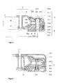
Bei der dargestellten Ausführungsvariante besteht der Innenring 3 aus dem Tragring 3c und dem Stützring 3d. Diese Drehverbindung enthält zur Abdichtung die Abdeckhaube 11, welche auch den Stauraum 10 und die Labyrinth-Dichtung 9 bildet sowie eine untere Dichtungspartie 8. Ebenfalls dargestellt sind die inneren Schrauben 7, welche nicht zur Drehverbindung gehören, sondern nur zum besseren Verständnis der Funktion gezeigt sind. Bekanntermassen kann der Innenring 3 der Gleitlager aus Metallblech hergestellt werden. Die Gleitelemente 2 bestehen meist aus Kunststoffen mit niedrigem Reibwert. Diese Elemente, welche zum Stand der Technik gehören, sind grundsätzlich auch bei der erfindungsgemässen Drehverbindung vorhanden, werden aber nicht weiter beschrieben.In the illustrated embodiment, the inner ring 3 consists of the support ring 3c and the support ring 3d. This rotary joint contains for sealing the cover 11, which also forms the storage space 10 and the labyrinth seal 9 and a lower sealing section 8. Also shown are the inner screws 7, which do not belong to the rotary joint, but are shown only for a better understanding of the function , As is known, the inner ring 3 of the plain bearings can be produced from sheet metal. The sliding elements 2 are usually made of plastics with a low coefficient of friction. These elements, which belong to the prior art, are basically also present in the inventive rotary joint, but will not be further described.

Der Teilkreis-Durchmesser 5a der dargestellten Drehverbindung beträgt 550mm, die Gesamthöhe hges ohne die Abdeckhaube 11 beträgt 54 mm. Die Gleitelemente 2 sind einteilig und weisen zwischen dem unteren Schenkel 2a und dem oberen Schenkel 2b eine Aussparung 2e auf. Diese Aussparung 2e ermöglicht es, das Gleitelement 2 so zu gestalten, dass sein Gelenkbereich 2k als elastisches Gelenk dient. Dadurch lässt sich der Gleitbahnbereich 2f des Gleitelementes 2 mittels in dieser Figur nicht sichtbarer Federn an die Haltebahn 3b des Innenringes 3 anpressen. Die Anpressfedern sind Stand der Technik und werden deshalb hier nicht dargestellt Sie spielen jedoch bei der Montage der erfindungsgemässen Ausführung eine Rolle und werden deshalb in dem dortigen Zusammenhang beschrieben und in Figur 4 dargestellt. Dank der Kombination von Elastizität und Anpressung lassen sich auch die Fertigungstoleranzen der einzelnen Teile überbrücken. Diese funktionell bedingte Aussparung 2e hat aber den Nachteil, dass die Herstellung der Gleitelemente dadurch relativ kompliziert und teuer wird. Bei grösseren Serien werden die Gleitelemente 2 üblicherweise gespritzt. Die Aussparung 2e bedingt dabei Formen mit sogenannten "Zügen". Die Nachteile dieser Gestaltung sind in der Beschreibung des technischen Standes erklärt. Aufgrund der Grundgestalt dieses Lagers, bei der der Innenringquerschnitt auf jeder Seite grob die Form eines liegenden V und die Gleitelemente die Form eines liegenden M haben wird diese Grundform auch als MV-Lager bezeichnet (siehe Fig. 2). Die geschlossene Kreisform der Drehverbindung hat aber zur Folge, dass Gleitdrehverbindungen in MV-Form nicht einfach wie die MV-Linearführungen gemäss Fig. 2 zusammengesetzt werden können, sondern dass der Aussenring 1 aus einem Aussenring-Unterteil 1a und einem Aussenring-Oberteil 1b bestehen muss und dass die Gleitelemente 2 keinen geschlossenen Ring bilden können, sondern einen segmentierten Ring aus mehreren Elementen. Die zweite Forderung stellt allerdings keinen praktischen Nachteil dar, weil die Gleitdrehverbindung aus funktionellen Gründen sowieso aus mehreren Gleitelementen 2 besteht. Üblicherweise sind das zwischen sechs und zweiunddreissig Gleitelemente 2. Nur für Anwendungen mit untergeordneten Ansprüchen und kleinen Stückzahlen ist eine Gleitdrehverbindung nach Offenlegungsschrift EP 2 554 802 A2 (Fig. 1) auch mit nur 2 Gleitelementen zweckmässig. Der M-förmige Querschnitt bedingt aber auch, wie im Stand der Technik beschrieben, eine aufwendige MontagemethodeThe pitch diameter 5a of the illustrated rotary joint is 550mm, the total height hges without the cover 11 is 54 mm. The sliding elements 2 are in one piece and have a recess 2e between the lower leg 2a and the upper leg 2b. This recess 2e makes it possible to design the sliding element 2 such that its joint area 2k serves as an elastic joint. As a result, the sliding track area 2f of the sliding element 2 can be pressed against the retaining track 3b of the inner ring 3 by means of springs which are not visible in this figure. The pressure springs are state of the art and are therefore not shown here but they play a role in the assembly of the inventive design and are therefore in the local Described in context and in FIG. 4 shown. Thanks to the combination of elasticity and pressure, the manufacturing tolerances of the individual parts can be bridged. However, this functionally related recess 2e has the disadvantage that the manufacture of the sliding elements becomes relatively complicated and expensive. For larger series, the sliding elements 2 are usually sprayed. The recess 2e requires forms with so-called "trains". The disadvantages of this design are explained in the description of the prior art. Due to the basic shape of this bearing, in which the inner ring cross section on each side roughly the shape of a horizontal V and the sliding elements have the shape of a lying M this basic shape is also referred to as MV bearing (see Fig. 2 ). However, the closed circular shape of the rotary joint has the consequence that Gleitdrehverbindungen in MV form not as easy as the MV linear guides according to Fig. 2 can be assembled, but that the outer ring 1 must consist of an outer ring lower part 1a and an outer ring upper part 1b and that the sliding elements 2 can not form a closed ring, but a segmented ring of a plurality of elements. However, the second requirement is not a practical disadvantage, because the Gleitdrehverbindung for functional reasons anyway consists of several sliding elements 2. These are usually between six and thirty-two sliding elements 2. Only for applications with subordinate claims and small numbers is a Gleitdrehverbindung according to published patent application EP 2 554 802 A2 ( Fig. 1 ) also with only 2 sliding appropriate. However, the M-shaped cross-section also requires, as described in the prior art, a complex mounting method

Fig. 2 zeigt eine Wälzlager-Linearführung in MV-Form. Dabei bedeutet 16 die M-Schiene, 17 eine einfache V-Schiene und 18 eine Doppel-V-Schiene. Die Linearführung enthält als Lagerkörper Zylinderrollen 19. Diese Zylinderrollen 19 werden im Winkelkäfig 20 gehalten und geführt. MV-Schienen sind Linearführungssysteme mit endlichem Hub. Üblicherweise bilden 2 Schienenpaare bestehend aus je einer M-Schiene 16 und einer einfachen V-Schiene 17 zusammen mit den Zylinderrollen 19 und dem Winkelkäfig 20 eine komplette MV-Linearführung. Bei Sonderausführungen, besonders bei kleinen Abständen zwischen den beiden Schienenpaaren, können die beiden inneren einfachen V-Schienen 17 auch zu einer Doppel-V-Schiene 18 vereinigt sein. Die beiden M-Schienen sind am einen Bauteil einer Maschine, zum Beispiel an einem Maschinengestell, befestigt, die beiden einfachen V-Schienen 17 an einem anderen Maschinenteil, zum Beispiel an einem Schlitten. Das Spiel oder allenfalls eine leichte Vorspannung von MV-Linearführungen werden dadurch eingestellt, dass eine Schiene, zum Beispiel eine M-Schiene 16 quer zur Bewegungsrichtung angestellt oder angepresst wird. Die Gleitdrehverbindung nach Fig. 1 entspricht im Querschnitt einer Wälzlager-Linearführung in MV-Form. Dabei entspricht der Innenring 3 der Drehverbindung einem Paar einfacher V-Schienen 17, die Gleitelemente 2 und der Aussenring 1 entsprechen zusammen dem Paar M-Schienen 16 und den Wälzkörpern 19. Infolge des geschlossenen Systems ist aber eine Einstellung des Spiels mittels Querverschiebung eines Lagerteiles nicht möglich. Deshalb weisen die Gleitdrehverbindungen Gleitelemente 2 mit einem Gelenkbereich 2k und den unter Fig. 4 beschriebenen Anpressfedern auf. Fig. 2 shows a rolling bearing linear guide in MV form. 16 means the M rail, 17 a simple V rail and 18 a double V rail. The linear guide contains as a bearing body cylindrical rollers 19. These cylindrical rollers 19 are held and guided in the angular cage 20. MV rails are finite stroke linear guide systems. Usually form two pairs of rails consisting of one M-rail 16 and a simple V-rail 17 together with the cylindrical rollers 19 and the angle cage 20 a complete MV linear guide. In special versions, especially at small distances between the two pairs of rails, the two inner simple V-rails 17 can also be combined to form a double V-rail 18. The two M-rails are attached to one component of a machine, for example on a machine frame, the two simple V-rails 17 on another machine part, for example on a carriage. The play or at best a slight bias of MV linear guides are adjusted by a rail, for example, an M-rail 16 is made or pressed transversely to the direction of movement. The Gleitdrehverbindung after Fig. 1 Corresponds in cross section to a roller bearing linear guide in MV form. The inner ring 3 of the rotary joint corresponds to a pair of simple V-rails 17, the sliding elements 2 and the outer ring 1 together correspond to the pair of M-rails 16 and the rolling elements 19. However, as a result of the closed system, an adjustment of the play by means of transverse displacement of a bearing part is not possible. Therefore, the Gleitdrehverbindungen sliding elements 2 with a hinge portion 2k and the lower Fig. 4 described pressure springs on.

Fig. 3 zeigt eine Ausführungsform der erfindungsgemässen Drehverbindung in einer axialen Querschnittsansicht durch die Stützhülsen 4 (Schnitt G-G in Fig. 6). Der Innenring 3 ist hier gemäss einer Variante der Drehverbindung gemäss EP 2554 802 dargestellt, bei welcher er aus dem Tragring 3c und den taillierten Stützhülsen 6 besteht. Sie ist ähnlich wie die Drehverbindung gemäss Fig. 1 ausgestaltet und gleiche Merkmale sind gleich ausgeführt, sie weist jedoch nachfolgend beschriebene erfindungsgemässe Verbesserungen auf. Jedes Gleitelement 2 besteht aus dem unteren Teilelement 2c und dem oberen Teilelement 2d. Das obere Teilelement 2d weist einen Klemmbord 2h, einen Brückenbereich 2j und einen Bereich mit der Gleitfläche 2f auf. Der Brückenbereich 2j ist elastisch und dient deshalb gleichzeitig als Gelenk. Die beiden Gleitelement-Teile unteres Teilelement 2c und oberes Teilelement 2d werden im kreuzweise schraffierten Druckbereich 2g durch den Aussenring-Oberteil 1b und den Aussenring-Unterteil 1a mittels der Schrauben 5 verspannt. Vor dem Verspannen hat es zwischen der oberen Stirnfläche 4a der Stützhülse 4 und dem horizontalen Bereich 1c des Aussenring-Oberteils 1b einen Spalt. Beim Anziehen der Schrauben 5 drückt der Aussenring-Oberteil 1b zuerst nur auf den kreuzweise schraffiert dargestellten Druckbereich 2g der beiden Gleitelementteile, der sich über das obere Teilelement 2d und das untere Teilelement 2c erstreckt. Beim weiteren Anziehen der Schrauben 5 verformt sich das Aussenring-Oberteil 1b leicht und liegt nun auch auf der Stirnfläche 4a der Stützhülse 4 auf. Dank dieser kraftschlüssigen Verbindung und der gegenseitigen Positionierung durch die Stützhülsen 4 wirken die zusammengesetzten Gleitelemente 2 gleich wie die einteiligen Gleitelemente 2 nach dem Stand der Technik in Fig. 1. Die kreuzweise schraffieren Teile, also der äussere Bereich des Aussenring-Unterteils 1a, der äussere Bereich des Aussenririg-Oberteils 1b, die Stützhülse 4 und der Klemmbereich 2g der Gleitelemente 2 bilden zusammen mit den Stützhülsen 4 wiederum den kastenartig geschlossenen Querschnitt. Funktionell sind die Ausführungen gemäss Fig. 1 und Fig. 3 gleichwertig. Fig. 3 shows an embodiment of the inventive rotary joint in an axial cross-sectional view through the support sleeves 4 (section GG in Fig. 6 ). The inner ring 3 is here according to a variant of the rotary joint according to EP 2554 802 shown, in which it consists of the support ring 3c and the waisted support sleeves 6. It is similar to the rotary joint according to Fig. 1 configured and the same features are the same, but it has described improvements according to the invention described below. Each sliding element 2 consists of the lower part element 2c and the upper part element 2d. The upper part member 2d has a clamping board 2h, a bridge portion 2j, and an area with the sliding surface 2f. The bridge region 2j is elastic and therefore simultaneously serves as a joint. The two sliding element parts lower sub-element 2c and upper sub-element 2d are clamped in the cross-hatched printing area 2g by the outer ring upper part 1b and the outer ring lower part 1a by means of the screws 5. Before the bracing, there is a gap between the upper end surface 4a of the support sleeve 4 and the horizontal portion 1c of the outer ring upper 1b. When tightening the screws 5, the outer ring upper part 1b first presses only on the cross-hatched pressure region 2g of the two sliding element parts, which extends over the upper part element 2d and the lower part element 2c. Upon further tightening of the screws 5, the outer ring upper part 1b deforms slightly and is now also on the end face 4a of the support sleeve 4. Thanks to this frictional connection and the mutual positioning by the support sleeves 4, the composite sliding elements 2 act the same as the one-piece sliding elements. 2 in the prior art Fig. 1 , The crosswise hatching parts, ie the outer region of the outer ring lower part 1a, the outer region of the Außenririg upper part 1b, the support sleeve 4 and the clamping portion 2g of the sliding elements 2 together with the support sleeves 4 turn the box-like closed cross-section. Functionally, the statements according to Fig. 1 and Fig. 3 equivalent.

Fig. 4 zeigt eine Ausführungsform der erfmdungsgemässen Drehverbindung mit einem System zum Verbinden der Teilelemente 2c und 2d sowie zum Vorspannen der Drehverbindung in einer axialen Querschnittsansicht durch das Federpaket 14 (Schnitt F-F in Fig. 6). Bei dieser Form dient die Schraube 13 gleichzeitig zum Verbinden des oberen Teilelementes 2d mit dem unteren Teilelementes 2c zu einem Gleitelement 2 sowie als Mittel zum stufenlosen Einstellen der Vorspannkraft auf die Drehverbindung. Die Vorspannkraft wird durch das Federpaket 14 erzeugt und über die Mutter 15 und die Vorspannschraube 13 auf das obere Teilelement 2d übertragen. Diese Schraubverbindung ermöglicht es, dass die Vorspannkraft jeder Drehverbindung optimal auf die spezifischen Anforderungen des zukünftigen Einsatzes abgestimmt werden kann. Die Mutter 15 ist in der Nut für Nutenstein 2y gegen Verdrehen gesichert. Bei der Montage der Drehverbindung werden zuerst die beiden Teilelemente zum kompletten Gleitelement 2 verbunden und anschliessend um den Innenring 3 gelegt. Dabei wird jeweils ein Gleitelement 2 mittels der Schnappverbindung 12 gemäss den Figuren 5 bis 8 der wachsenden Kette von Gleitelementen 2 beigefügt und am Schluss das vorerst offene C zu einem geschlossenen Ring verbunden. Darauf wird der Aussenring-Oberteil 1b über die Montagegruppe bestehend aus Innenring 3 und Gleitelementen 2 gelegt und darauf diese ganze Montagegruppe auf den Kopf gestellt. Anschliessend werden die Stützhülsen 4 (Fig. 3) eingesetzt und der Aussenring-Unterteil 1a aufgesetzt. Die komplette Drehverbindung wird zum Schluss mit 3 oder 4 Schrauben 5 (Fig. 3) für Lagerung und Transport verbunden. Fig. 4 shows an embodiment of the inventive rotary joint with a system for connecting the sub-elements 2c and 2d and for biasing the rotary joint in an axial cross-sectional view through the spring assembly 14 (section FF in Fig. 6 ). In this form, the screw 13 serves at the same time for connecting the upper sub-element 2 d with the lower sub-element 2 c to a sliding member 2 and as a means for continuously adjusting the biasing force on the rotary joint. The biasing force is generated by the spring assembly 14 and transmitted via the nut 15 and the biasing screw 13 to the upper sub-element 2 d. This bolted connection allows the preload force of each slewing ring to be optimally matched to the specific requirements of future use. The nut 15 is secured in the groove for sliding block 2y against rotation. When mounting the rotary joint, the two sub-elements are first connected to the complete sliding element 2 and then placed around the inner ring 3. In each case, a sliding element 2 by means of the snap connection 12 according to the FIGS. 5 to 8 attached to the growing chain of sliding elements 2 and connected at the end the initially open C to a closed ring. Then the outer ring upper part 1b is placed over the assembly group consisting of inner ring 3 and sliding elements 2 and placed on this whole assembly group upside down. Subsequently, the support sleeves 4 ( Fig. 3 ) and the outer ring lower part 1a placed. The complete slewing connection is finished with 3 or 4 screws 5 ( Fig. 3 ) for storage and transport.

Fig. 5 zeigt eine Ausführungsform der erfindungsgemässen Drehverbindung mit einem zusätzlichen Funktionselement. Die Fig. 5 zeigt dabei nebeneinander eine (rechts, in Fig. 5b, dargestellte) radiale und eine (links, in Fig. 5a, dargestellte) tangentiale Schnittansicht durch den Verbindungsbereich zweier nebeneinander liegender Gleitelemente 2 mit einer Ausführungsform des Verbindungssystems. Hinzu tritt mit der Fig. 6 eine Schnittansicht in einer Ebene rechtwinklig zur Drehachse mit dem Verbindungssystem nach Fig. 5 bestehend aus Zapfen und T-Bohrung. Fig. 5 shows an embodiment of the inventive rotary joint with an additional functional element. The Fig. 5 shows one next to each other (right, in Fig. 5b , shown) radial and one (left, in Fig. 5a , shown) tangential sectional view through the connecting portion of two adjacent sliding elements 2 with an embodiment of the connection system. Add to that with the Fig. 6 a sectional view in a plane perpendicular to the axis of rotation with the connection system according to Fig. 5 consisting of pin and T-hole.

Bei den Gleitelementen 2 dieser Ausführungsform ist ein Verbindungssystem in Form einer Schnappverbindung 12 integriert, welche das Zusammenstecken der einzelnen Gleitelemente 2 zu einem geschlossenen Ring ermöglicht. Durch diese Schnappverbindung 12 wird die Montage der Drehverbindung wesentlich erleichtert, wodurch die Montagezeit reduziert und die gesamte Baugruppe verbilligt wird. Die Schnitte der
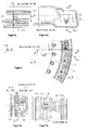
 Fig. 5 zeigen die Drehverbindung etwa im Massstab 1:1.4. Die Schnittebene der Darstellung links liegt tangential parallel zur z-Achse, diejenige rechts ist eine radiale x-z-Ebene. Dieser Radialschnitt verläuft im Spalt zwischen zwei Elementen. Um diese Schnappverbindung besser darstellen zu können, ist sie in Figur 7 etwa im Massstab 2:1 vergrössert (insbesondere gegenüber den Darstellungen der Fig. 5) dargestellt.In the sliding elements 2 of this embodiment, a connection system in the form of a snap connection 12 is integrated, which allows the mating of the individual sliding elements 2 to form a closed ring. By this snap connection 12, the assembly of the rotary joint is much easier, whereby the assembly time is reduced and the entire assembly is cheaper. The cuts of Fig. 5 show the rotary joint approximately on a scale of 1: 1.4. The sectional plane of the representation on the left lies tangentially parallel to the z-axis, that on the right is a radial xz-plane. This radial section runs in the gap between two elements. To better illustrate this snap connection, she is in FIG. 7 enlarged on a scale of 2: 1 (especially in comparison to the illustrations of the Fig. 5 ).

Die Figs. 5 bis 7 zeigen beispielhaft eine Ausführungsform des erfindungsgemässen Verbindungssystems. Sinnvollerweise enthält jedes Gleitelement am einen Ende die Öffnung oder Steckdose einer Art Druckknopfsystem und am anderen Ende den pilzförmigen Steckzapfen. Das erfindungsgemässe Verbindungssystem kann aber auch realisiert werden, indem zwei Arten von Gleitelementen verwendet werden. Ein Typ enthält dann an jedem Ende eine Steckdose und der andere Typ an jedem Ende einen Steckzapfen. Vorteilhafterweise sind dabei die Verbindungskomponenten des Verbindungssystems einstückig in die Gleitelemente 2 integriert.The Figs. 5 to 7 show an example of an embodiment of the inventive connection system. It makes sense that each slider at one end of the opening or socket of a kind of push button system and at the other end of the mushroom-shaped spigot. However, the connection system according to the invention can also be realized by using two types of sliding elements. One type then contains a socket at each end and the other type has a plug at each end. Advantageously, the connection components of the connection system are integrally integrated into the sliding elements 2.

Fig. 6 ist ein Horizontal-Teilschnitt durch eine erfindungsgemässe Drehverbindung. Der Schnittverlauf C-C ist in Fig. 5 angegeben. Gleichzeitig ist in Fig. 6 die Schnittlinie A-A der Darstellung der Fig. 5b (rechts) eingezeichnet. In dieser Figur 6 sind auch die Achsen bezeichnet. Diese Darstellung, etwa im Massstab 1:2, gibt einen Überblick über das Verbindungssystem. Fig. 6 is a horizontal partial section through an inventive rotary joint. The sectioning CC is in Fig. 5 specified. At the same time is in Fig. 6 the section line AA of the representation of Fig. 5b (right). In this FIG. 6 are also called the axes. This representation, on a scale of 1: 2, gives an overview of the connection system.

Fig. 7 zeigt die in den Figuren 5 und 6 grob beschriebene Ausführungsform eines Verbindungssystems im Detail, wobei die Schnittdarstellung der Fig. 7a (links), sich aus der Darstellung der Fig. 5a (links), entlang der Linie D-D ergibt. Die Darstellung der Fig. 7b (rechts) ist eine Schnittdarstellung der Fig. 7a (links), die sich aus der Darstellung entlang der Linie E-E ergibt. Bei dieser Ausführungsform der Schnappverbindung weist jedes untere Teilelement 2c am einen Ende in Umfangsrichtung einen Verbindungszapfen 21 und am andern Ende eine T-Nut 2q auf. Der Durchmesser des Zapfenkopfes 2n und die Breite des Nut-Hinterstiches 2s sind grösser als der zugehörige Durchmesser des Zapfenhalses 2m und grösser als die Breite des Nuthalses 2r. Dank dem Schlitz 2p lässt sich der Zapfenkopf 2n durch den Nuthals 2r in den Nut-Hinterstich 2s schieben. Nach der Passage durch den Nuthals 2r kann der Verbindungszapfen 21 wieder in seine ursprüngliche Form zurückfedern. Dadurch werden die zwei nebeneinander liegenden Gleitelemente 2 miteinander verbunden. Die Gleitelemente 2 sind zweckmässigerweise bereits gemäss der Beschreibung zu Fig. 4 mittels der Vorspannschrauben 13 und der Mutter 15 zu einer Montagegruppe verbunden. Die Komponenten sind also dabei an jedem freien Ende von jedem Teilelement 2c bzw. 2d in Umfangsrichtung vorgesehen, um mit komplementären Komponenten des benachbarten Teilelements verbindbar zu sein. Das Grundprinzip der Schnappverbindung ist der pilzförmige Zapfen mit einer komplementären hinterschnittenen Ausnehmung. Fig. 7 shows the in the FIGS. 5 and 6 roughly described embodiment of a connection system in detail, wherein the sectional view of Fig. 7a (left), from the representation of the Fig. 5a (left), along the line DD results. The presentation of the Fig. 7b (right) is a sectional view of the Fig. 7a (left), resulting from the representation along the line EE results. In this embodiment of the snap connection, each lower sub-element 2c has at one end in the circumferential direction a connecting pin 21 and at the other end a T-slot 2q. The diameter of the pin head 2n and the width of the groove-undercut 2s are greater than the associated diameter of the pin neck 2m and greater than the width of Nuthalses 2r. Thanks to the slot 2p, the pin head 2n can be pushed through the groove neck 2r into the groove-undercut 2s. After passing through the Nuthals 2r, the connecting pin 21 spring back into its original shape. As a result, the two adjacent sliding elements 2 are connected to each other. The sliding elements 2 are expediently already according to the description Fig. 4 connected by means of the biasing screws 13 and the nut 15 to a mounting group. The components are thus provided at each free end of each sub-element 2c and 2d in the circumferential direction to be connectable with complementary components of the adjacent sub-element. The basic principle of the snap connection is the mushroom-shaped pin with a complementary undercut recess.

Aus fertigungstechnischen Gründen ist die Mitte des Verbindungszapfens 21 in der Trennebene 2w des Spritzwerkzeuges. Aus dem gleichen Grund wird am anderen Ende des unteren Teilelementes 2c keine Bohrung angebracht, sondern nur eine im Schnitt E-E U-förmige T-Nut 2q. Durch diese T-Nut 2q im unteren Teilelement 2c sind die Gleitelemente aber erst in radialer und tangentialer Richtung verbunden sowie in einer axialen Richtung. Zur Fixierung in der axialen Gegenrichtung ist am oberen Teilelement 2d deshalb ein Verschluss-Nocken 2t angebracht. Damit fixiert die Schnappverbindung 12 die nebeneinander liegenden Gleitelemente in allen Richtungen. Die Schnappverbindungen 12 weisen aber soviel Spiel auf, dass der noch c-förmig offene Ring der Gleitelemente zum Einsetzen des letzten Gleitelementes etwas geöffnet werden kann.For manufacturing reasons, the center of the connecting pin 21 in the parting plane 2w of the injection molding tool. For the same reason, no bore is provided at the other end of the lower subelement 2c, but only a T-groove 2q which is U-shaped in section E-E. By means of this T-slot 2q in the lower part element 2c, however, the sliding elements are connected only in the radial and tangential direction and in an axial direction. For fixing in the axial opposite direction, therefore, a closing cam 2t is attached to the upper part element 2d. Thus, the snap connection 12 fixes the adjacent sliding elements in all directions. However, the snap connections 12 have so much game that the still c-shaped ring open the sliding elements for insertion of the last sliding element can be opened slightly.

Fig. 8 zeigt eine Drehverbindung mit einem ähnlichen Verbindungssystem für die Gleitelemente 2 wie die Figs. 5-7 nach einem weiteren Ausführungsbeispiel der Erfindung. Die drei Einzeldarstellungen ergeben sich als Schnitte nach den Linien A-A (Fig. 8c), B-B (Fig. 8a) und C-C (Fig. 8b) in dieser Fig. 8. Auch bei dieser Ausführungsform ist das Verbindungssystem eine Schnappverbindung 12. Sie besteht aus je zwei Verbindungszapfen 2 1 sowie zwei T-Nuten 2q pro Gleitelement. Sowohl das untere Teilelement 2c wie das obere Teilelement 2d enthalten jeweils am einen Ende einen Verbindungszapfen 2 1 und am anderen Ende eine T-Nut 2q. Der Schnappvorgang wird beim unteren Teilelement 2c erreicht durch zwei elastische Lappen 2v und beim oberen Teilelement 2d durch den elastischen Zapfenhals 2u. Dadurch können die Gleitelemente 2 in gleicher Weise zusammengesteckt werden wie diejenigen gemäss den Figs. 5-7. Hier ist das Verbindungssystem im unteren Teilelement 2c unterhalb der unteren Oberfläche der Aussparung 2e in dem Material des Teilelementes versenkt, während im oberen Teilelement 2d der angespritzte Zapfen in diese Aussparung hineinragt, da die Bauhöhe des oberen Teilelementes 2d in der dargestellten Ausführungsform kleiner als die notwendige Bauhöhe für die Nut-Feder-Verbindung ist. Das kann natürlich auch umgekehrt vorgesehen sein. Das Verbindungssystem ist in einem radialen Abstand von der Mitte des Lagers vorgesehen, der kleiner als der Mittenabstand der Stützhülsen 4 ist. Da die durch das Verbindungssystem erreichte Verbindung der einzelnen Teilelemente 2c oder 2d Spiel aufweist, kann die Wahl des Radius im oberen bzw. unteren Teilelement 2c oder 2d unterschiedlich sein und sich insbesondere nach räumlichen Gesichtspunkten richten. Insbesondere können die Verbindungssysteme an unterschiedlichen Radien vorgesehen sein. Fig. 8 shows a rotary joint with a similar connection system for the sliding elements 2 as the Figs. 5-7 according to a further embodiment of the invention. The three individual representations are shown as sections along the lines AA ( Fig. 8c ), BB ( Fig. 8a ) and CC ( Fig. 8b ) in this Fig. 8 , It also consists of two connecting pins 2 1 and two T-slots 2q per slider. Both the lower one Sub-element 2c as the upper sub-element 2d each contain at one end a connecting pin 2 1 and at the other end a T-slot 2q. The snap action is achieved at the lower part element 2c by two elastic lobes 2v and the upper part element 2d by the elastic pin neck 2u. As a result, the sliding elements 2 can be put together in the same way as those according to FIGS Figs. 5-7 , Here, the connection system in the lower subelement 2c is recessed below the lower surface of the recess 2e in the material of the subelement, while in the upper subelement 2d the molded spigot projects into this recess, since the overall height of the upper subelement 2d in the illustrated embodiment is smaller than the necessary Overall height for the tongue and groove connection is. Of course, this can also be provided vice versa. The connection system is provided at a radial distance from the center of the bearing, which is smaller than the center distance of the support sleeves 4. Since the connection of the individual partial elements 2c or 2d achieved by the connection system has clearance, the choice of the radius in the upper or lower partial element 2c or 2d can be different and can be directed in particular from a spatial point of view. In particular, the connection systems can be provided at different radii.

Ebenso kann der gleiche Grundgedanke realisiert werden, indem jedes Gleitelement an jedem Ende eine Steckdose bildende Ausnehmung, beispielsweise nach der Schnittdarstellung A-A der Fig. 8 mit in dieser vorgesehenen zwei flexiblen Enden 2v, enthält und die Gleitelemente 2c bzw. 2d durch getrennte Verbindungszapfen-Elemente, die für jede Verbindung zwischen zwei benachbarten Gleitelementen vorgesehen sind, miteinander verbunden werden. Diese sind dann hantelförmig mit zwei Verdickungen an den gegenüberliegenden Enden und einem Mittelabschnitt mit reduziertem Durchmesser.Likewise, the same basic idea can be realized by each slider at each end of an outlet forming recess, for example, according to the sectional view of the AA Fig. 8 with two flexible ends 2v provided therein, and the sliding members 2c and 2d, respectively, are interconnected by separate connecting pin members provided for each connection between two adjacent sliding members. These are then dumbbell-shaped with two thickenings at the opposite ends and a central portion of reduced diameter.

Fig. 9 zeigt eine alternative Ausführungsform zum Verbindungs- und Vorspannsystem gemäss Fig. 4. Gleiche oder ähnliche Merkmale, wie sie im Zusammenhang mit der Fig. 4 beschrieben worden sind, haben hier die gleichen Bezugszeichen erhalten und werden im folgenden nicht mehr getrennt erläutert. In vielen Anwendungsfällen ist die stufenlose Einstellung der Vorspannkraft, wie sie in der Ausführungsform gemäss Fig. 4 vorgesehen ist, nicht notwendig. Fig. 9 shows an alternative embodiment of the connection and biasing system according to Fig. 4 , Same or similar characteristics as those associated with the Fig. 4 have been described here, the same reference numerals have been obtained and will not be explained separately in the following. In many applications, the continuous adjustment of the biasing force, as in the embodiment according to Fig. 4 is provided, not necessary.

Für diese Fälle zeigt die Fig. 9 ein Verbindungssystem für die beiden Teilelemente 2c und 2d, welches wiederum dank der zweiteiligen Ausführung der Gleitelemente besonders günstig ausgeführt werden kann. Diese Ausführung kann mit der Stützhülse 6 des Innenrings 3 kombiniert werden. Der Verbindungsbolzen 21 bildet dabei zusammen mit den Vorspannfedern 14 ein zweistufiges Verbindungssystem für die Teilelemente 2c, 2d in Form eines Drehverschlusses. Der Verbindungsbolzen 21 ist oben schlüsselartig mit zwei Verriegelungsflügeln 21 a versehen und in der Mitte mit zwei Positionierflügeln 21b; er hat dadurch ungefähr die Form eines Schlüssels mit 2 Doppelbärten.For these cases shows the Fig. 9 a connection system for the two sub-elements 2c and 2d, which in turn can be carried out particularly low thanks to the two-part design of the sliding elements. This embodiment can be combined with the support sleeve 6 of the inner ring 3. The connecting pin 21 forms together with the biasing springs 14, a two-stage connection system for the sub-elements 2c, 2d in the form of a rotary closure. The connecting pin 21 is above key-like with two locking wings 21 a and provided in the middle with two positioning wings 21 b; He has about the shape of a key with 2 double beards.

Diese Form erkennt man insbesondere im Schnitt H-H in Fig. 9b. Im Bereich der Verriegelungsflügel 21 a und der Positionierflügel 21 b sind die Querschnitte identisch. Der Querschnitt der Durchgänge 21c in den Teilelementen 2c und 2d entspricht dem Querschnitt des Verbindungsbolzens im Bereich der Verriegelungsflügel 21a, ist aber natürlich leicht grösser, sodass der Verbindungsbolzen 21 leicht durch die Durchgänge 21 c geschoben werden kann.This form can be seen in particular in the section HH in Fig. 9b , In the area of the locking wings 21 a and the positioning wings 21 b, the cross sections are identical. The cross section of the passages 21 c in the sub-elements 2 c and 2 d corresponds to the cross-section of the connecting bolt in the region of the locking wings 21 a, but of course is slightly larger, so that the connecting pin 21 can be easily pushed through the passages 21 c.

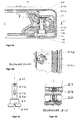
Zum Verbinden der Teilelemente 2c und 2 d werden diese "auf den Kopf" gestellt, das heisst das obere Teilelement 2d unten und das untere Teilelement 2c oben angeordnet, und in eine Montageunterlage gelegt. Das Federpaket 14 wird auf den Verbindungsbolzen 21 gesteckt und dieser anschliessend durch die Durchgänge 21c geschoben. Die Montageunterlage weist eine Anschlagfläche für die Stirnfläche 21j des Verbindungsbolzens 21 auf. Der Verbindungsbolzen 21 wird soweit in die Durchgänge 21c hineingestossen, bis er auf der Anschlagfläche der Montageunterlage ansteht. Nun wird der Verbindungsbolzen mit einem Schraubenzieher über den Schlitz 21d im Bolzenkopf um 45° gedreht. Die richtige Position für diese Drehbewegung ist mit einem Pfeil 21g auf dem Nutgrund 21f gekennzeichnet. Nun wird der Schraubenzieher weggezogen und das Federpaket 14 fixiert die Positionierflügel 21b mit der Positionierkerbe 21e am Rasterkamm 22. Die Teilelemente 2c und 2d sind nun so miteinander verbunden, dass sie beim Zusammenfügen der einzelnen Gleitelemente 2 um den Innenring 3 genau an der Tragbahn 3a und der Haltebahn 3b des Innenringes anliegen, ohne durch das Federpaket 14 nach aussen gedrückt zu werden. Die Gleitelemente werden nun wieder so umgedreht, dass das untere Teilelement 2c unten und das obere Teilelement 2c oben ist. Anschliessend fügt man die vormontierten Gleitelemente 2 mittels der Verbindungszapfen 21 zu einer Ringkette zusammen und legt sie gleichzeitig um den Innenring 3. Die Baugruppe bestehend aus dem Innenring 3 und dem Ring aus den Gleitelementen 2 wird nun in den Aussenring-Unterteil 1a eingesetzt.To connect the sub-elements 2c and 2d, these are placed "upside down", that is, the upper sub-element 2d below and the lower sub-element 2c arranged above, and placed in a mounting pad. The spring assembly 14 is placed on the connecting pin 21 and this subsequently pushed through the passages 21 c. The mounting pad has a stop surface for the end face 21j of the connecting pin 21. The connecting pin 21 is pushed so far into the passages 21 c until it is present on the stop surface of the mounting pad. Now, the connecting bolt is turned with a screwdriver over the slot 21d in the bolt head by 45 °. The correct position for this rotational movement is indicated by an arrow 21g on the groove bottom 21f. Now, the screwdriver is pulled away and the spring assembly 14 fixes the positioning 21b with the positioning notch 21e on the ratchet 22. The sub-elements 2c and 2d are now connected to each other so that when assembling the individual sliding elements 2 to the inner ring 3 exactly on the support track 3a and abut the retaining track 3b of the inner ring, without being pressed by the spring assembly 14 to the outside. The sliding elements are now turned over again so that the lower part element 2c below and the upper part element 2c is up. Subsequently, one adds the pre-assembled sliding elements 2 by means of the connecting pin 21 to a Ring chain together and puts them at the same time around the inner ring 3. The assembly consisting of the inner ring 3 and the ring of the sliding elements 2 is now inserted into the outer ring lower part 1a.

Darauf werden die Stützhülsen 4 (siehe Fig. 4) eingesetzt und die Ringkette aus den Gleitelementen 2 auf die Befestigungsbohrungen 1d ausgerichtet. Nun kann man die Verbindungsbolzen 21 über den Schlitz 21h um weitere 45° drehen. Dabei werden die Positionierflügel 21b aus dem Rasterkamm 22 gehoben; die Verriegelungsflügel 21a werden durch das Federpaket 14 in die Sicherungsnut 23 gezogen und damit formschlüssig in ihrer Lage gesichert. Gleichzeitig wird die Vorspannkraft der Federpakete 14 auf die Gleitflächen 2f, 2x, 3a und 3b (Fig. 3) aufgebracht. Die Drehverbindung wird zum Schluss fertig montiert.Then the support sleeves 4 (see Fig. 4 ) and aligned the ring chain of the sliding elements 2 on the mounting holes 1d. Now you can turn the connecting pin 21 through the slot 21h by another 45 °. The positioning wings 21b are lifted out of the raster comb 22; the locking wings 21a are pulled by the spring assembly 14 in the securing groove 23 and thus secured in a form-fitting manner in their position. At the same time, the biasing force of the spring assemblies 14 on the sliding surfaces 2f, 2x, 3a and 3b ( Fig. 3 ) applied. The rotary joint is finally assembled.

Fig. 10 zeigt eine Ausführungsform der erfindungsgemässen Drehverbindung mit einem System zum Vorspannen der Drehverbindung in einer axialen Querschnittsansicht durch das Federpaket 14. Bei dieser Form dient die Schraube 13 gleichzeitig zum stufenlosen Einstellen der Vorspannkraft auf die Drehverbindung sowie als Mittel zum Verbinden des oberen Teilelementes 2d mit dem unteren Teilelement 2c zu einem Gleitelement 2. Die Vorspannkraft wird durch das Federpaket 14 erzeugt und über die Mutter 15 und die Vorspannschraube 13 auf das obere Teilelement 2d übertragen. Diese Schraubverbindung ermöglicht es, dass die Vorspannkraft jeder Drehverbindung optimal auf die spezifischen Anforderungen des zukünftigen Einsatzes abgestimmt werden kann. Die Mutter 15 ist in der Sechskantaussparung 14d in das untere Teilelement 2c eingegossen und damit gegen Verdrehen gesichert. An die Mutter 15 schliesst sich die Sicherungspartie 14e an. Die Bohrung in dieser Partie ist einige Zehntelmillimeter kleiner als der Aussendurchmesser der Vorspannschraube 13. Beim Eindrehen der Vorspannschraube 13 in die Sicherungspartie 14e muss deshalb diese Sicherungspartie verformt werden. Die dazu notwendigen Verformungskräfte sichern die Vorspannschraube gegen losdrehen. Bei kleinen Fertigungslosen können die Gleitelemente 2 auch aus Kunststoff-Halbfabrikaten spanend hergestellt anstatt gespritzt werden. Bei diesem Herstellverfahren kann natürlich die Sechskantaussparung 14d bis zur Stirnfläche des unteren Teilelementes 2c gezogen werden. Die Mutter kann dann eingepresst oder eingeklebt und die Vorspannschraube zum Beispiel mit Klebstoffen gesichert werden. Die Federbüchse 14a ist mit einer Fase 14b versehen. Diese Fase erleichtert das Positionieren des oberen Teilelementes 2d gegenüber dem zuerst eingebauten unteren Teilelement 2c und trägt damit zusätzlich zur Reduktion der Montagezeit bei. BEZUGSZEICHENLISTE 1 Aussenring 3 Innenring 1a Aussenring-Unterteil 3a Tragbahn 1b Aussenring-Oberteil 3b Haltebahn 1c horizontaler Bereich 3c Tragring 1d Befestigungsbohrung 3d Stützring 1e Zentrierteil des Aussenrings 4 Stützhülse 2 Gleitelement 4a Stirnfläche 2a Unterer Schenkel 5 Schrauben 2b Oberer Schenkel 5a Teilkreis-Durchmesser 2c Unteres Teilelement 6 Taillierte Stützhülse 2d Oberes Teilelement 7 innere Schraube 2e Aussparung 8 Dichtungspartie 2f Obere Gleitfläche 9 Labyrinth-Dichtung 2g Druckbereich 10 Stauraum 2h Klemmbord 11 Abdeckhaube 2j Brückenbereich 12 Schnappverbindung 2k Gelenkbereich 13 Vorspannschraube 21 Verbindungszapfen 14 Federpaket 2m Zapfenhals 14a Federbüchse 2n Zapfenkopf 14b Fase 2p Schlitz 14c Ansenkung 2q T-Nut 14d Sechskantaussparung 2r Nuthals 14e Sicherungspartie 2s Nut-Hinterstich 15 Mutter 2t Verschluss-Nocken 16 M-Schiene 2u Elastischer Zapfenhals 17 einfache V-Schiene 2v Elastische Lappen 18 Doppel-V-Schiene 2w Trennebene 19 Zylinderrollen 2x Untere Gleitfläche 20 Winkelkäfig 2y Nut für Nutenstein 21 Verbindungsbolzen 2z Nutgrund 21a Verriegelungsflügel 21b Positionierflügel 21c Durchgang 21d Schlitz im Bolzenkopf 21e Positionierkerbe 21f obere Stirnfläche 21g Pfeil 21h oberer Schlitz 21j Stirnfläche 22 Rasterkamm 23 Sicherungsnut Fig. 10 shows an embodiment of the inventive rotary joint with a system for biasing the rotary joint in an axial cross-sectional view through the spring assembly 14. In this form, the screw 13 serves simultaneously for continuously adjusting the biasing force on the rotary joint and as a means for connecting the upper sub-element 2 d with the lower Sub-element 2c to a sliding element 2. The biasing force is generated by the spring assembly 14 and transmitted via the nut 15 and the biasing screw 13 to the upper sub-element 2d. This bolted connection allows the preload force of each slewing ring to be optimally matched to the specific requirements of future use. The nut 15 is poured into the hexagonal recess 14 d in the lower part element 2 c and thus secured against rotation. The securing part 14e adjoins the nut 15. The bore in this lot is a few tenths of a millimeter smaller than the outer diameter of the preloading screw 13. When screwing the preloading screw 13 into the securing part 14e therefore this securing part must be deformed. The necessary deformation forces secure the preload screw against unscrewing. For small production lots, the sliding elements 2 can also be produced from plastic semi-finished products instead of being sprayed. In this manufacturing method, of course, the hexagonal recess 14d can be pulled to the end face of the lower part element 2c. The nut can then be pressed or glued and the preload screw secured with, for example, adhesives. The spring sleeve 14a is provided with a chamfer 14b Provided. This chamfer facilitates the positioning of the upper sub-element 2d in relation to the first sub-element 2c installed first and thus additionally contributes to the reduction of the assembly time. LIST OF REFERENCE NUMBERS 1 outer ring 3 inner ring 1a Outer Ring base 3a supporting race 1b Outer ring shell 3b retention sheet 1c horizontal area 3c support ring 1d mounting hole 3d support ring 1e Centering part of the outer ring 4 support sleeve 2 Slide 4a face 2a Lower thigh 5 screw 2 B Upper thigh 5a Pitch circle diameter 2c Lower subelement 6 Waisted support sleeve 2d Upper part element 7 inner screw 2e recess 8th seal area 2f Upper sliding surface 9 Labyrinth seal 2g pressure range 10 storage space 2h terminal board 11 cover 2y bridge area 12 snap 2k joint area 13 preloading screw 21 connecting pins 14 spring assembly 2m pin neck 14a spring sleeve 2n tapping head 14b chamfer 2p slot 14c countersink 2q T-slot 14d Hexagonal recess 2r slot neck 14e backup game 2s Groove undercut 15 mother 2t Lock cam 16 M-rail 2u Elastic neck neck 17 simple V-rail 2v Elastic rag 18 Double-V-rail 2w parting plane 19 cylindrical rollers 2x Lower sliding surface 20 angle cage 2y Groove for sliding block 21 connecting bolts 2z groove base 21a locking wings 21b positioning tab 21c passage 21d Slot in the bolt head 21e positioning groove 21f upper face 21g arrow 21h upper slot 21j face 22 grid comb 23 securing groove

Claims (15)

Drehverbindungs-Lager auf Gleitlagerbasis mit den Funktionseinheiten Aussenring (1), Innenring (3) und zwischen diesen angeordneten Gleitelementen als Lagerkörper, dadurch gekennzeichnet, dass jedes Gleitelement (2) aus zwei Teilelementen (2c, 2d) besteht, von denen jedes eine im Wesentlichen konische Gleitfläche (2f, 2x) aufweist und dass das eine Teilelement (2d) jedes Gleitelementes (2) aus einem Bereich mit dem Klemmbord (2h), einem Brückenbereich (2j) und einem Bereich mit der Gleitfläche (2f) besteht.Jointed plain bearing with the functional units outer ring (1), inner ring (3) and arranged between these sliding elements as a bearing body, characterized in that each sliding element (2) consists of two sub-elements (2c, 2d), each of which is a substantially has conical sliding surface (2f, 2x) and that the one partial element (2d) of each sliding element (2) consists of an area with the clamping board (2h), a bridge area (2j) and a region with the sliding surface (2f). Drehverbindungs-Lager nach Anspruch 1, dadurch gekennzeichnet, dass die Gleitelemente (2) im Wesentlichen einen M-förmigen Querschnitt aufweisen.Rotary connection bearing according to claim 1, characterized in that the sliding elements (2) have a substantially M-shaped cross-section. Drehverbindungs-Lager nach Anspruch 1 oder 2, dadurch gekennzeichnet, dass jedes Gleitelement (2) an jedem freien Ende in Umfangsrichtung Verbindungskomponenten (2q bzw. 2 1) eines Verbindungssystems aufweist, mit der die Elemente miteinander verbunden werden können.Rotary joint bearing according to claim 1 or 2, characterized in that each sliding element (2) has at each free end in the circumferential direction connecting components (2q or 2 1) of a connection system, with which the elements can be interconnected. Drehverbindungs-Lager nach Anspruch 3, dadurch gekennzeichnet, dass die Verbindungskomponenten (2q bzw. 2 1) eine Schnappverbindung (12) des Typs Druckknopf bilden.Rotary connection bearing according to claim 3, characterized in that the connection components (2q or 2 1) form a snap connection (12) of the push-button type. Drehverbindungs-Lager nach Anspruch 4, dadurch gekennzeichnet, dass die Schnappverbindung (12) aus einem pilzförmigen Zapfen (21) am einen Ende jedes Gleitelementes (2c bzw. 2d) und einer hinterschnittenen Ausnehmung (2q) am anderen Ende jedes Gleitelementes (2c bzw. 2d) besteht und dass eine der Verbindungskomponenten so elastisch ist, dass die Verbindung beim Zusammenstecken einschnappt.Rotary joint bearing according to claim 4, characterized in that the snap connection (12) consists of a mushroom-shaped pin (21) at one end of each sliding element (2c or 2d) and an undercut recess (2q) at the other end of each sliding element (2c or 2c). 2d) and that one of the connection components is so elastic that the connection snaps when mating. Drehverbindungs-Lager nach einem der Ansprüche 3 bis 5, dadurch gekennzeichnet, dass die Verbindungskomponenten des Verbindungssystems einstückig in die Gleitelemente (2) integriert sind.Rotary joint bearing according to one of claims 3 to 5, characterized in that the connection components of the connection system in one piece in the sliding elements (2) are integrated. Drehverbindungs-Lager nach einem der Ansprüche 3 bis 5, dadurch gekennzeichnet, dass die Gleitelemente (2) an jedem freien Ende Aufnahmen für getrennte Verbindungselemente aufweisen.Rotary connection bearing according to one of claims 3 to 5, characterized in that the sliding elements (2) have receptacles for separate connecting elements at each free end. Drehverbindungs-Lager nach einem der Ansprüche 1 bis 7, dadurch gekennzeichnet, dass mindestens einer der Ringe (1, 3) einen Raum aufspannt und dass die Raumstruktur des Aussen- (1) und/oder des Innenringes (3) mindestens aus einem in Umfangsrichtung geschlossenen, aus flächigen Elementen bestehenden Ring (1 oder 3) und entlang dem Umfang verteilten und durch die gegenüberliegenden flächigen Elemente durchgreifenden Stützelementen (4, 6) gebildet wird.Rotary connection bearing according to one of claims 1 to 7, characterized in that at least one of the rings (1, 3) spans a space and that the spatial structure of the outer (1) and / or the inner ring (3) at least one in the circumferential direction closed, consisting of flat elements ring (1 or 3) and distributed along the circumference and by the opposing planar elements by cross-supporting elements (4, 6) is formed. Drehverbindungs-Lager nach Anspruch 8, dadurch gekennzeichnet, dass die Drehverbindung einen Aussenring (1) und einen Innenring (3) mit kastenförmigem Querschnitt aufweist.Rotary connection bearing according to claim 8, characterized in that the rotary connection has an outer ring (1) and an inner ring (3) with box-shaped cross-section. Drehverbindungs-Lager nach einem der Ansprüche 1 bis 9, dadurch gekennzeichnet, dass die beiden Teilelemente (2c, 2d) durch Verbindungselemente (21) miteinander verbunden werden.Rotary connection bearing according to one of claims 1 to 9, characterized in that the two sub-elements (2c, 2d) by connecting elements (21) are interconnected. Drehverbindungs-Lager nach einem der Ansprüche 1 bis 10, dadurch gekennzeichnet, dass die Verbindungselemente (21) einen Drehverschluss bilden und so ausgebildet sind, dass eine Verbindung in zwei Schritten möglich ist, wobei im ersten Schritt die Teilelemente (2c, 2d) für die Montage verbunden werden, dass die Gleitflächen (2f, 2x) die Tragbahn (3a) und die Haltebahn (3b) gerade berühren, und dass im zweiten Schritt die Vorspannung des Federpaketes (14) auf die Gleitflächen (2f) aufgebracht wird.Rotary joint bearing according to one of claims 1 to 10, characterized in that the connecting elements (21) form a rotary closure and are designed so that a connection in two steps is possible, wherein in the first step, the sub-elements (2c, 2d) for the Assembly are connected, that the sliding surfaces (2f, 2x) the support track (3a) and the retaining track (3b) just touch, and that in the second step, the bias of the spring assembly (14) on the sliding surfaces (2f) is applied. Drehverbindungs-Lager nach einem der Ansprüche 1 bis 11, dadurch gekennzeichnet, dass die Teilelemente (2c, 2d) mit einem Rasterkamm (22) und einer Sicherungsnut (23) versehen sind, welche das Verbindungselement (21) mittels Positionierkerben (21e) in der Montageposition fixieren und mittels Verriegelungsflügel (21a) in der Betriebsposition sichern.Rotary joint bearing according to one of claims 1 to 11, characterized in that the sub-elements (2c, 2d) with a ratchet (22) and a securing groove (23) are provided, which the connecting element (21) by means of positioning notches (21e) in the Fix mounting position and secure by means of locking wing (21a) in the operating position. Drehverbindungs-Lager nach einem der Ansprüche 1 bis 12, dadurch gekennzeichnet, dass die Teilelemente (2c, 2d) dreidimensionale Körper sind, insbesondere aus Kunststoff hergestellt. Drehverbindungs-Lager nach einem der Ansprüche 1 bis 11, dadurch gekennzeichnet, dass die Teilelemente (2c, 2d).Rotary connection bearing according to one of claims 1 to 12, characterized in that the sub-elements (2c, 2d) are three-dimensional body, in particular made of plastic. Rotary connection bearing according to one of claims 1 to 11, characterized in that the sub-elements (2c, 2d). Drehverbindungs-Lager nach einem der Ansprüche 1 bis 13, dadurch gekennzeichnet, dass die unteren Teilelemente (2c) und die oberen Teilelemente (2d) durch den Aussenring- Oberteil (1b) miteinander verspannt sind.Rotary connection bearing according to one of claims 1 to 13, characterized in that the lower part elements (2c) and the upper part elements (2d) by the outer ring upper part (1b) are clamped together. Drehverbindungs-Lager nach einem der Ansprüche 1 bis 14, dadurch gekennzeichnet, dass die Mutter (15) in das untere Teilelement (2c) eingegossen wird und dass sich an die Mutter eine Sicherungspartie (14e) anschliesst, deren Bohrungsdurchmesser etwas kleiner ist als der Aussendurchmesser der Vorspannschraube, wodurch die die Vorspannschraube (13) gegen Losdrehen gesichert wird.Rotary connection bearing according to one of Claims 1 to 14, characterized in that the nut (15) is cast into the lower part element (2c) and that a securing part (14e) adjoins the nut, whose bore diameter is slightly smaller than the outer diameter the preload screw, which is the biasing screw (13) secured against loosening.
EP15405018.1A 2014-02-27 2015-02-26 Slewing bearing with sliding elements Not-in-force EP2913544B1 (en)

Applications Claiming Priority (1)

Application Number Priority Date Filing Date Title
CH2962014 2014-02-27

Publications (3)

Publication Number Publication Date
EP2913544A2 true EP2913544A2 (en) 2015-09-02
EP2913544A3 EP2913544A3 (en) 2015-10-07
EP2913544B1 EP2913544B1 (en) 2018-03-28

Family

ID=52630307

Family Applications (1)

Application Number Title Priority Date Filing Date
EP15405018.1A Not-in-force EP2913544B1 (en) 2014-02-27 2015-02-26 Slewing bearing with sliding elements

Country Status (1)

Country Link
EP (1) EP2913544B1 (en)

Cited By (2)

* Cited by examiner, † Cited by third party
Publication number Priority date Publication date Assignee Title
EP3299645A1 (en) * 2016-09-26 2018-03-28 Rudolf Gehring Slewing bearing on base of sliding bearing with drive structures
CN108393684A (en) * 2018-05-03 2018-08-14 华中科技大学无锡研究院 A kind of adjustable float device

Citations (5)

* Cited by examiner, † Cited by third party
Publication number Priority date Publication date Assignee Title
FR972570A (en) 1948-09-29 1951-01-31 Smooth pad
CH459668A (en) 1966-06-03 1968-07-15 Skf Svenska Kullagerfab Ab Axial and radial plain bearing
CH691191A5 (en) 2000-01-06 2001-05-15 Rudolf Ing Htl Gehring Rotating joint designed as slide bearing, comprising inner or outer ring made of heavy sheet metal
US20120183246A1 (en) 2009-09-29 2012-07-19 Ntn Corporation Sliding bearing
EP2554802A2 (en) 2011-08-04 2013-02-06 Rudolf Gehring Slewing bearing with sliding element

Family Cites Families (4)

* Cited by examiner, † Cited by third party
Publication number Priority date Publication date Assignee Title
CH281535A (en) * 1950-01-07 1952-03-15 Keller Friedrich Ring plain bearings.
DE102005047625A1 (en) * 2005-10-05 2007-04-12 Kurz Tribotechnik Radial plain bearing has stationary inner bearing element, outer race rotating around axis of rotation, inner bearing surface surrounding active surface of inner bearing element and axial protection device for axial protection of race
DK2376797T3 (en) * 2008-12-15 2016-08-22 Jochen Corts Segmented composite bearings and wind generator that uses hydraulic pump / motor combination
DE102011013692B4 (en) * 2011-03-11 2015-06-18 Voith Patent Gmbh Bearing arrangement for receiving the axial thrust of a shaft

Patent Citations (5)

* Cited by examiner, † Cited by third party
Publication number Priority date Publication date Assignee Title
FR972570A (en) 1948-09-29 1951-01-31 Smooth pad
CH459668A (en) 1966-06-03 1968-07-15 Skf Svenska Kullagerfab Ab Axial and radial plain bearing
CH691191A5 (en) 2000-01-06 2001-05-15 Rudolf Ing Htl Gehring Rotating joint designed as slide bearing, comprising inner or outer ring made of heavy sheet metal
US20120183246A1 (en) 2009-09-29 2012-07-19 Ntn Corporation Sliding bearing
EP2554802A2 (en) 2011-08-04 2013-02-06 Rudolf Gehring Slewing bearing with sliding element

Cited By (2)

* Cited by examiner, † Cited by third party
Publication number Priority date Publication date Assignee Title
EP3299645A1 (en) * 2016-09-26 2018-03-28 Rudolf Gehring Slewing bearing on base of sliding bearing with drive structures
CN108393684A (en) * 2018-05-03 2018-08-14 华中科技大学无锡研究院 A kind of adjustable float device

Also Published As

Publication number Publication date
EP2913544B1 (en) 2018-03-28
EP2913544A3 (en) 2015-10-07

Similar Documents

Publication Publication Date Title
DE3931397C2 (en)
EP0472167B1 (en) Rolling contact bearing for linear movement, say rail guided rollers
EP0211243B1 (en) Rolling-contact bearing for linear movement
DE3416207A1 (en) LINEAR BALL BEARING ARRANGEMENT
DE102011000769A1 (en) Axial radial roller bearings, in particular for the storage of rotor blades on a wind turbine
EP2426050B1 (en) Bearing element of a rudder bearing
DE3227902C2 (en) Linear ball bearing unit
CH660215A5 (en) ROLL REFLECTOR.
DE3304641A1 (en) ROLLER BEARING LONGITUDINAL GUIDE FOR UNLIMITED SLIDING PATHS
DE3843096A1 (en) FASTENING DEVICE FOR FAIRING
DE102016216286A1 (en) Segmented roller bearing cage and cage segment to form the same
DE102011003376B4 (en) segment cage
EP2913544B1 (en) Slewing bearing with sliding elements
DE3620571A1 (en) Rolling bearing for linear motions
EP2649331B1 (en) Radial rolling bearing with loose spacing bodies between the rolling elements and method of assembling the rolling bearing
AT400881B (en) SPINDLE LIFT GEARBOX
DE3910457A1 (en) LINEAR BALL RIFLE
WO2008043531A1 (en) Injection mold for the production of a window unit comprising a window and a frame
EP1552149B1 (en) Stator for a progressive cavity pump
DE102012002361B4 (en) Die plate for die bushings of a rotary tablet press and rotor with such a die plate
DE3418621A1 (en) Rolling bearing
DE3512858A1 (en) LINEAR BALL BEARING KEYWORD: RADIAL COMPACT GUIDE
DE1956836A1 (en) Rolling bearing arrangement and method for its manufacture
DE102018127682B4 (en) Arrangement with an adjustment device for adjusting the position of two components connected to one another
CH691191A5 (en) Rotating joint designed as slide bearing, comprising inner or outer ring made of heavy sheet metal

Legal Events

Date Code Title Description
PUAI Public reference made under article 153(3) epc to a published international application that has entered the european phase

Free format text: ORIGINAL CODE: 0009012

AK Designated contracting states

Kind code of ref document: A2

Designated state(s): AL AT BE BG CH CY CZ DE DK EE ES FI FR GB GR HR HU IE IS IT LI LT LU LV MC MK MT NL NO PL PT RO RS SE SI SK SM TR

AX Request for extension of the european patent

Extension state: BA ME

PUAL Search report despatched

Free format text: ORIGINAL CODE: 0009013

AK Designated contracting states

Kind code of ref document: A3

Designated state(s): AL AT BE BG CH CY CZ DE DK EE ES FI FR GB GR HR HU IE IS IT LI LT LU LV MC MK MT NL NO PL PT RO RS SE SI SK SM TR

AX Request for extension of the european patent

Extension state: BA ME

RIC1 Information provided on ipc code assigned before grant

Ipc: F16C 35/02 20060101ALI20150828BHEP

Ipc: F16C 25/02 20060101ALI20150828BHEP

Ipc: F16C 17/10 20060101AFI20150828BHEP

Ipc: F16C 33/04 20060101ALI20150828BHEP

Ipc: F16C 33/20 20060101ALN20150828BHEP

Ipc: F16C 43/02 20060101ALI20150828BHEP

Ipc: F16C 33/26 20060101ALI20150828BHEP

17P Request for examination filed

Effective date: 20160225

RBV Designated contracting states (corrected)

Designated state(s): AL AT BE BG CH CY CZ DE DK EE ES FI FR GB GR HR HU IE IS IT LI LT LU LV MC MK MT NL NO PL PT RO RS SE SI SK SM TR

17Q First examination report despatched

Effective date: 20160810

STAA Information on the status of an ep patent application or granted ep patent

Free format text: STATUS: EXAMINATION IS IN PROGRESS

RIC1 Information provided on ipc code assigned before grant

Ipc: F16C 33/04 20060101ALI20171003BHEP

Ipc: F16C 17/10 20060101ALI20171003BHEP

Ipc: F16C 25/02 20060101ALI20171003BHEP

Ipc: F16C 33/20 20060101ALN20171003BHEP

Ipc: F16C 11/06 20060101AFI20171003BHEP

Ipc: F16C 43/02 20060101ALI20171003BHEP

REG Reference to a national code

Ref country code: DE

Ref legal event code: R079

Ref document number: 502015003606

Country of ref document: DE

Free format text: PREVIOUS MAIN CLASS: F16C0017100000

Ipc: F16C0011060000

GRAP Despatch of communication of intention to grant a patent

Free format text: ORIGINAL CODE: EPIDOSNIGR1

STAA Information on the status of an ep patent application or granted ep patent

Free format text: STATUS: GRANT OF PATENT IS INTENDED

RIC1 Information provided on ipc code assigned before grant

Ipc: F16C 33/20 20060101ALN20171107BHEP

Ipc: F16C 25/02 20060101ALI20171107BHEP

Ipc: F16C 33/04 20060101ALI20171107BHEP

Ipc: F16C 43/02 20060101ALI20171107BHEP

Ipc: F16C 17/10 20060101ALI20171107BHEP

Ipc: F16C 11/06 20060101AFI20171107BHEP

RIC1 Information provided on ipc code assigned before grant

Ipc: F16C 33/04 20060101ALI20171123BHEP

Ipc: F16C 33/20 20060101ALN20171123BHEP

Ipc: F16C 25/02 20060101ALI20171123BHEP

Ipc: F16C 11/06 20060101AFI20171123BHEP

Ipc: F16C 43/02 20060101ALI20171123BHEP

Ipc: F16C 17/10 20060101ALI20171123BHEP

RIC1 Information provided on ipc code assigned before grant

Ipc: F16C 33/04 20060101ALI20171124BHEP

Ipc: F16C 43/02 20060101ALI20171124BHEP

Ipc: F16C 17/10 20060101ALI20171124BHEP

Ipc: F16C 11/06 20060101AFI20171124BHEP

Ipc: F16C 33/20 20060101ALN20171124BHEP

Ipc: F16C 25/02 20060101ALI20171124BHEP

INTG Intention to grant announced

Effective date: 20171213

GRAS Grant fee paid

Free format text: ORIGINAL CODE: EPIDOSNIGR3

GRAA (expected) grant

Free format text: ORIGINAL CODE: 0009210

STAA Information on the status of an ep patent application or granted ep patent

Free format text: STATUS: THE PATENT HAS BEEN GRANTED

AK Designated contracting states

Kind code of ref document: B1

Designated state(s): AL AT BE BG CH CY CZ DE DK EE ES FI FR GB GR HR HU IE IS IT LI LT LU LV MC MK MT NL NO PL PT RO RS SE SI SK SM TR

REG Reference to a national code

Ref country code: GB

Ref legal event code: FG4D

Free format text: NOT ENGLISH

REG Reference to a national code

Ref country code: CH

Ref legal event code: EP

REG Reference to a national code

Ref country code: AT

Ref legal event code: REF

Ref document number: 983719

Country of ref document: AT

Kind code of ref document: T

Effective date: 20180415

REG Reference to a national code

Ref country code: IE

Ref legal event code: FG4D

Free format text: LANGUAGE OF EP DOCUMENT: GERMAN

REG Reference to a national code

Ref country code: DE

Ref legal event code: R096

Ref document number: 502015003606

Country of ref document: DE

PG25 Lapsed in a contracting state [announced via postgrant information from national office to epo]

Ref country code: FI

Free format text: LAPSE BECAUSE OF FAILURE TO SUBMIT A TRANSLATION OF THE DESCRIPTION OR TO PAY THE FEE WITHIN THE PRESCRIBED TIME-LIMIT

Effective date: 20180328

Ref country code: LT

Free format text: LAPSE BECAUSE OF FAILURE TO SUBMIT A TRANSLATION OF THE DESCRIPTION OR TO PAY THE FEE WITHIN THE PRESCRIBED TIME-LIMIT

Effective date: 20180328

Ref country code: NO

Free format text: LAPSE BECAUSE OF FAILURE TO SUBMIT A TRANSLATION OF THE DESCRIPTION OR TO PAY THE FEE WITHIN THE PRESCRIBED TIME-LIMIT

Effective date: 20180628

Ref country code: HR

Free format text: LAPSE BECAUSE OF FAILURE TO SUBMIT A TRANSLATION OF THE DESCRIPTION OR TO PAY THE FEE WITHIN THE PRESCRIBED TIME-LIMIT

Effective date: 20180328

REG Reference to a national code

Ref country code: NL

Ref legal event code: MP

Effective date: 20180328

REG Reference to a national code

Ref country code: LT

Ref legal event code: MG4D

PG25 Lapsed in a contracting state [announced via postgrant information from national office to epo]

Ref country code: BG

Free format text: LAPSE BECAUSE OF FAILURE TO SUBMIT A TRANSLATION OF THE DESCRIPTION OR TO PAY THE FEE WITHIN THE PRESCRIBED TIME-LIMIT

Effective date: 20180628

Ref country code: RS

Free format text: LAPSE BECAUSE OF FAILURE TO SUBMIT A TRANSLATION OF THE DESCRIPTION OR TO PAY THE FEE WITHIN THE PRESCRIBED TIME-LIMIT

Effective date: 20180328

Ref country code: SE

Free format text: LAPSE BECAUSE OF FAILURE TO SUBMIT A TRANSLATION OF THE DESCRIPTION OR TO PAY THE FEE WITHIN THE PRESCRIBED TIME-LIMIT

Effective date: 20180328

Ref country code: LV

Free format text: LAPSE BECAUSE OF FAILURE TO SUBMIT A TRANSLATION OF THE DESCRIPTION OR TO PAY THE FEE WITHIN THE PRESCRIBED TIME-LIMIT

Effective date: 20180328

Ref country code: GR

Free format text: LAPSE BECAUSE OF FAILURE TO SUBMIT A TRANSLATION OF THE DESCRIPTION OR TO PAY THE FEE WITHIN THE PRESCRIBED TIME-LIMIT

Effective date: 20180629

PG25 Lapsed in a contracting state [announced via postgrant information from national office to epo]

Ref country code: MT

Free format text: LAPSE BECAUSE OF FAILURE TO SUBMIT A TRANSLATION OF THE DESCRIPTION OR TO PAY THE FEE WITHIN THE PRESCRIBED TIME-LIMIT

Effective date: 20180328

PG25 Lapsed in a contracting state [announced via postgrant information from national office to epo]

Ref country code: PL

Free format text: LAPSE BECAUSE OF FAILURE TO SUBMIT A TRANSLATION OF THE DESCRIPTION OR TO PAY THE FEE WITHIN THE PRESCRIBED TIME-LIMIT

Effective date: 20180328

Ref country code: EE

Free format text: LAPSE BECAUSE OF FAILURE TO SUBMIT A TRANSLATION OF THE DESCRIPTION OR TO PAY THE FEE WITHIN THE PRESCRIBED TIME-LIMIT

Effective date: 20180328

Ref country code: ES

Free format text: LAPSE BECAUSE OF FAILURE TO SUBMIT A TRANSLATION OF THE DESCRIPTION OR TO PAY THE FEE WITHIN THE PRESCRIBED TIME-LIMIT

Effective date: 20180328

Ref country code: RO

Free format text: LAPSE BECAUSE OF FAILURE TO SUBMIT A TRANSLATION OF THE DESCRIPTION OR TO PAY THE FEE WITHIN THE PRESCRIBED TIME-LIMIT

Effective date: 20180328

Ref country code: NL

Free format text: LAPSE BECAUSE OF FAILURE TO SUBMIT A TRANSLATION OF THE DESCRIPTION OR TO PAY THE FEE WITHIN THE PRESCRIBED TIME-LIMIT

Effective date: 20180328

Ref country code: AL

Free format text: LAPSE BECAUSE OF FAILURE TO SUBMIT A TRANSLATION OF THE DESCRIPTION OR TO PAY THE FEE WITHIN THE PRESCRIBED TIME-LIMIT

Effective date: 20180328

PG25 Lapsed in a contracting state [announced via postgrant information from national office to epo]

Ref country code: SK

Free format text: LAPSE BECAUSE OF FAILURE TO SUBMIT A TRANSLATION OF THE DESCRIPTION OR TO PAY THE FEE WITHIN THE PRESCRIBED TIME-LIMIT

Effective date: 20180328

Ref country code: SM

Free format text: LAPSE BECAUSE OF FAILURE TO SUBMIT A TRANSLATION OF THE DESCRIPTION OR TO PAY THE FEE WITHIN THE PRESCRIBED TIME-LIMIT

Effective date: 20180328

Ref country code: CZ

Free format text: LAPSE BECAUSE OF FAILURE TO SUBMIT A TRANSLATION OF THE DESCRIPTION OR TO PAY THE FEE WITHIN THE PRESCRIBED TIME-LIMIT

Effective date: 20180328

PG25 Lapsed in a contracting state [announced via postgrant information from national office to epo]

Ref country code: PT

Free format text: LAPSE BECAUSE OF FAILURE TO SUBMIT A TRANSLATION OF THE DESCRIPTION OR TO PAY THE FEE WITHIN THE PRESCRIBED TIME-LIMIT

Effective date: 20180730

REG Reference to a national code

Ref country code: DE

Ref legal event code: R097

Ref document number: 502015003606

Country of ref document: DE

PG25 Lapsed in a contracting state [announced via postgrant information from national office to epo]

Ref country code: DK

Free format text: LAPSE BECAUSE OF FAILURE TO SUBMIT A TRANSLATION OF THE DESCRIPTION OR TO PAY THE FEE WITHIN THE PRESCRIBED TIME-LIMIT

Effective date: 20180328

PLBE No opposition filed within time limit

Free format text: ORIGINAL CODE: 0009261

STAA Information on the status of an ep patent application or granted ep patent

Free format text: STATUS: NO OPPOSITION FILED WITHIN TIME LIMIT

PG25 Lapsed in a contracting state [announced via postgrant information from national office to epo]

Ref country code: IT

Free format text: LAPSE BECAUSE OF FAILURE TO SUBMIT A TRANSLATION OF THE DESCRIPTION OR TO PAY THE FEE WITHIN THE PRESCRIBED TIME-LIMIT

Effective date: 20180328

26N No opposition filed

Effective date: 20190103

PGFP Annual fee paid to national office [announced via postgrant information from national office to epo]

Ref country code: FR

Payment date: 20190329

Year of fee payment: 5

Ref country code: GB

Payment date: 20190325

Year of fee payment: 5

PG25 Lapsed in a contracting state [announced via postgrant information from national office to epo]

Ref country code: SI

Free format text: LAPSE BECAUSE OF FAILURE TO SUBMIT A TRANSLATION OF THE DESCRIPTION OR TO PAY THE FEE WITHIN THE PRESCRIBED TIME-LIMIT

Effective date: 20180328

PG25 Lapsed in a contracting state [announced via postgrant information from national office to epo]

Ref country code: LU

Free format text: LAPSE BECAUSE OF NON-PAYMENT OF DUE FEES

Effective date: 20190226

Ref country code: MC

Free format text: LAPSE BECAUSE OF FAILURE TO SUBMIT A TRANSLATION OF THE DESCRIPTION OR TO PAY THE FEE WITHIN THE PRESCRIBED TIME-LIMIT

Effective date: 20180328

REG Reference to a national code

Ref country code: BE

Ref legal event code: MM

Effective date: 20190228

REG Reference to a national code

Ref country code: IE

Ref legal event code: MM4A

PG25 Lapsed in a contracting state [announced via postgrant information from national office to epo]

Ref country code: IE

Free format text: LAPSE BECAUSE OF NON-PAYMENT OF DUE FEES

Effective date: 20190226

PG25 Lapsed in a contracting state [announced via postgrant information from national office to epo]

Ref country code: BE

Free format text: LAPSE BECAUSE OF NON-PAYMENT OF DUE FEES

Effective date: 20190228

PG25 Lapsed in a contracting state [announced via postgrant information from national office to epo]

Ref country code: TR

Free format text: LAPSE BECAUSE OF FAILURE TO SUBMIT A TRANSLATION OF THE DESCRIPTION OR TO PAY THE FEE WITHIN THE PRESCRIBED TIME-LIMIT

Effective date: 20180328

GBPC Gb: european patent ceased through non-payment of renewal fee

Effective date: 20200226

PG25 Lapsed in a contracting state [announced via postgrant information from national office to epo]

Ref country code: GB

Free format text: LAPSE BECAUSE OF NON-PAYMENT OF DUE FEES

Effective date: 20200226

REG Reference to a national code

Ref country code: AT

Ref legal event code: MM01

Ref document number: 983719

Country of ref document: AT

Kind code of ref document: T

Effective date: 20200226

PG25 Lapsed in a contracting state [announced via postgrant information from national office to epo]

Ref country code: CY

Free format text: LAPSE BECAUSE OF FAILURE TO SUBMIT A TRANSLATION OF THE DESCRIPTION OR TO PAY THE FEE WITHIN THE PRESCRIBED TIME-LIMIT

Effective date: 20180328

Ref country code: AT

Free format text: LAPSE BECAUSE OF NON-PAYMENT OF DUE FEES

Effective date: 20200226

PGFP Annual fee paid to national office [announced via postgrant information from national office to epo]

Ref country code: DE

Payment date: 20210225

Year of fee payment: 7

PG25 Lapsed in a contracting state [announced via postgrant information from national office to epo]

Ref country code: IS

Free format text: LAPSE BECAUSE OF FAILURE TO SUBMIT A TRANSLATION OF THE DESCRIPTION OR TO PAY THE FEE WITHIN THE PRESCRIBED TIME-LIMIT

Effective date: 20180728

PG25 Lapsed in a contracting state [announced via postgrant information from national office to epo]

Ref country code: HU

Free format text: LAPSE BECAUSE OF FAILURE TO SUBMIT A TRANSLATION OF THE DESCRIPTION OR TO PAY THE FEE WITHIN THE PRESCRIBED TIME-LIMIT; INVALID AB INITIO

Effective date: 20150226

PG25 Lapsed in a contracting state [announced via postgrant information from national office to epo]

Ref country code: FR

Free format text: LAPSE BECAUSE OF NON-PAYMENT OF DUE FEES

Effective date: 20210228

PGFP Annual fee paid to national office [announced via postgrant information from national office to epo]

Ref country code: CH

Payment date: 20220107

Year of fee payment: 8

PG25 Lapsed in a contracting state [announced via postgrant information from national office to epo]

Ref country code: MK

Free format text: LAPSE BECAUSE OF FAILURE TO SUBMIT A TRANSLATION OF THE DESCRIPTION OR TO PAY THE FEE WITHIN THE PRESCRIBED TIME-LIMIT

Effective date: 20180328

REG Reference to a national code

Ref country code: DE

Ref legal event code: R119

Ref document number: 502015003606

Country of ref document: DE

PG25 Lapsed in a contracting state [announced via postgrant information from national office to epo]

Ref country code: DE

Free format text: LAPSE BECAUSE OF NON-PAYMENT OF DUE FEES

Effective date: 20220901

REG Reference to a national code

Ref country code: CH

Ref legal event code: PL

PG25 Lapsed in a contracting state [announced via postgrant information from national office to epo]

Ref country code: LI

Free format text: LAPSE BECAUSE OF NON-PAYMENT OF DUE FEES

Effective date: 20230228

Ref country code: CH

Free format text: LAPSE BECAUSE OF NON-PAYMENT OF DUE FEES

Effective date: 20230228