EP2913507A1 - Cooling structure for cylinder head - Google Patents
Cooling structure for cylinder head Download PDFInfo
- Publication number
- EP2913507A1 EP2913507A1 EP13849755.7A EP13849755A EP2913507A1 EP 2913507 A1 EP2913507 A1 EP 2913507A1 EP 13849755 A EP13849755 A EP 13849755A EP 2913507 A1 EP2913507 A1 EP 2913507A1
- Authority
- EP
- European Patent Office
- Prior art keywords
- water jacket
- exhaust manifold
- collector
- communication passage
- coolant
- Prior art date
- Legal status (The legal status is an assumption and is not a legal conclusion. Google has not performed a legal analysis and makes no representation as to the accuracy of the status listed.)
- Ceased
Links
Images


Classifications
-
- F—MECHANICAL ENGINEERING; LIGHTING; HEATING; WEAPONS; BLASTING
- F02—COMBUSTION ENGINES; HOT-GAS OR COMBUSTION-PRODUCT ENGINE PLANTS
- F02F—CYLINDERS, PISTONS OR CASINGS, FOR COMBUSTION ENGINES; ARRANGEMENTS OF SEALINGS IN COMBUSTION ENGINES
- F02F1/00—Cylinders; Cylinder heads
- F02F1/24—Cylinder heads
- F02F1/26—Cylinder heads having cooling means
- F02F1/36—Cylinder heads having cooling means for liquid cooling
- F02F1/38—Cylinder heads having cooling means for liquid cooling the cylinder heads being of overhead valve type
-
- F—MECHANICAL ENGINEERING; LIGHTING; HEATING; WEAPONS; BLASTING
- F01—MACHINES OR ENGINES IN GENERAL; ENGINE PLANTS IN GENERAL; STEAM ENGINES
- F01P—COOLING OF MACHINES OR ENGINES IN GENERAL; COOLING OF INTERNAL-COMBUSTION ENGINES
- F01P3/00—Liquid cooling
- F01P3/02—Arrangements for cooling cylinders or cylinder heads
-
- F—MECHANICAL ENGINEERING; LIGHTING; HEATING; WEAPONS; BLASTING
- F02—COMBUSTION ENGINES; HOT-GAS OR COMBUSTION-PRODUCT ENGINE PLANTS
- F02F—CYLINDERS, PISTONS OR CASINGS, FOR COMBUSTION ENGINES; ARRANGEMENTS OF SEALINGS IN COMBUSTION ENGINES
- F02F1/00—Cylinders; Cylinder heads
- F02F1/24—Cylinder heads
- F02F1/243—Cylinder heads and inlet or exhaust manifolds integrally cast together
-
- F—MECHANICAL ENGINEERING; LIGHTING; HEATING; WEAPONS; BLASTING
- F02—COMBUSTION ENGINES; HOT-GAS OR COMBUSTION-PRODUCT ENGINE PLANTS
- F02F—CYLINDERS, PISTONS OR CASINGS, FOR COMBUSTION ENGINES; ARRANGEMENTS OF SEALINGS IN COMBUSTION ENGINES
- F02F1/00—Cylinders; Cylinder heads
- F02F1/24—Cylinder heads
- F02F1/26—Cylinder heads having cooling means
- F02F1/36—Cylinder heads having cooling means for liquid cooling
- F02F1/40—Cylinder heads having cooling means for liquid cooling cylinder heads with means for directing, guiding, or distributing liquid stream
-
- F—MECHANICAL ENGINEERING; LIGHTING; HEATING; WEAPONS; BLASTING
- F01—MACHINES OR ENGINES IN GENERAL; ENGINE PLANTS IN GENERAL; STEAM ENGINES
- F01P—COOLING OF MACHINES OR ENGINES IN GENERAL; COOLING OF INTERNAL-COMBUSTION ENGINES
- F01P3/00—Liquid cooling
- F01P3/02—Arrangements for cooling cylinders or cylinder heads
- F01P2003/027—Cooling cylinders and cylinder heads in parallel
-
- F—MECHANICAL ENGINEERING; LIGHTING; HEATING; WEAPONS; BLASTING
- F02—COMBUSTION ENGINES; HOT-GAS OR COMBUSTION-PRODUCT ENGINE PLANTS
- F02F—CYLINDERS, PISTONS OR CASINGS, FOR COMBUSTION ENGINES; ARRANGEMENTS OF SEALINGS IN COMBUSTION ENGINES
- F02F1/00—Cylinders; Cylinder heads
- F02F1/24—Cylinder heads
- F02F1/42—Shape or arrangement of intake or exhaust channels in cylinder heads
- F02F1/4264—Shape or arrangement of intake or exhaust channels in cylinder heads of exhaust channels
- F02F2001/4278—Exhaust collectors
Definitions
- the present disclosure relates to a cooling structure for cooling a cylinder head that accommodates an exhaust manifold.
- Japanese Laid-Open Patent Publication No. 2010-275915 describes a cylinder head in which upper and lower water jackets are respectively arranged above and below an exhaust manifold to cover the exhaust manifold.
- the exhaust manifold is cooled by a coolant flowing through each water jacket.
- Patent Document 1 Japanese Laid-Open Patent Publication No. 2010-275915
- the cylinder head accommodates an exhaust manifold, a first water jacket, a second water jacket, a plurality of communication passages, and a coolant outlet.
- the exhaust manifold includes a plurality of branches and a collector. The branches are respectively connected to combustion chambers of cylinders. The branches converge at the collector.
- the first water jacket is located above the exhaust manifold and covers the exhaust manifold including at least the collector.
- the second water jacket is located below the exhaust manifold and covers the exhaust manifold including at least the collector.
- the communication passages supply coolant from the second water jacket to the first water jacket.
- the coolant outlet connects the first water jacket to the exterior.
- the cooling structure for the cylinder head is configured so that the coolant flows from each water jacket in a direction in which the cylinders are arranged in order to be discharged out of the coolant outlet.
- the communication passages include a first communication passage and a second communication passage.
- the first communication passage is located at an upstream side of the collector in a flow direction of the coolant and arranged at a position that is the most proximate to the collector.
- the second communication passage is located in a downstream side end of each water jacket.
- a cross-sectional passage area of the second communication passage is set to be smaller than a cross-sectional passage area of the first communication passage.
- the collector of the exhaust manifold tends to have a high temperature due to heat of the exhaust.
- the exhaust manifold is curved so that a portion at a downstream side is located below a portion at an upstream side.
- the exhaust flowing to the exhaust manifold from the combustion chamber tends to strike an upper portion of an inner wall of the exhaust manifold.
- the collector particularly, an upper portion of the collector, tends to have a high temperature.
- the configuration described above effectively cools the exhaust manifold, particularly, the upper portion of the collector, which tends to have a high temperature. More specifically, in the above configuration, a coolant supplied to a lower water jacket, which serves as the second water jacket, flows in the cylinder arrangement direction. Some of the coolant flows to the second communication passage arranged in the downstream side end of the second water jacket. Then, the coolant flows to an upper water jacket, which serves as the first water jacket, through the second communication passage and is discharged from the coolant outlet arranged in the first water jacket.
- the cross-sectional passage area of the second communication passage is set to be smaller than the cross-sectional passage area of the first communication passage.
- the upper portion of the exhaust manifold tends to have a high temperature compared to the lower portion.
- the first water jacket is set so that an area of the exhaust manifold that is covered by the first water jacket is larger than an area of the exhaust manifold that is covered by the second water jacket. This mode effectively cools the upper portion of the exhaust manifold, which tends to have a high temperature while limiting excessive cooling of the lower portion of the exhaust manifold.
- the communication passages include a third communication passage located at a downstream side of the collector in the flow direction of the coolant.
- the collector is located between the third communication passage and the first communication passage.
- the coolant is supplied to a portion that covers the two opposite sides of the collector through the first communication passage and the third communication passage. This effectively cools not only the upper side of the collector but also the sides of the collector.
- the second communication passage includes a downstream side opening that opens to the first water jacket.
- the second communication is configured so that a flow passage direction of the downstream side opening extends toward the coolant outlet.
- the coolant which is supplied to the first water jacket from the second communication passage, flows toward the coolant outlet. This generates flow of the coolant toward the coolant outlet in the first water jacket. Consequently, more coolant may be discharged to the exterior from the coolant outlet. This increases the amount of the coolant flowing through each of the water jackets, thereby effectively cooling the exhaust manifold.
- a cylinder head 20 is arranged above a cylinder block 10 in an internal combustion engine.
- the cylinder head 20 includes an exhaust manifold 21 that is in communication with a combustion chamber 30.
- the exhaust manifold 21 is curved so that a portion at a downstream side of the exhaust is located below a portion at an upstream side of the exhaust, which is at the side of the combustion chamber 30.
- the cylinder head 20 includes an upper water jacket 22, which is arranged above the exhaust manifold 21 and serves as a first water jacket, and a lower water jacket 23, which is arranged below the exhaust manifold 21 and serves as a second water jacket.
- the lower water jacket 23 is in communication with a coolant passage 11 formed in the cylinder block 10.
- the exhaust manifold 21 includes a plurality of branches 211, which are connected to the combustion chambers 30, and a collector 212.
- the branches 211 converge into the collector 212.
- the lower water jacket 23 extends in a direction in which cylinders are arranged (left-right direction in the drawing) and covers the collector 212 of the exhaust manifold 21 from a lower side.
- An area in which the lower water jacket 23 covers the exhaust manifold 21 is set to be 40% or less of the surface area of a lower portion of the exhaust manifold 21.
- the exhaust manifold 21, which is indicated by broken lines, includes a plurality of ends that are located below the lower water jacket 23 (located toward the cylinder block 10).
- the lower water jacket 23 includes a first end and a second end in the cylinder arrangement direction (left-right direction in Fig. 2 ).
- the first end includes a first inlet 24 to which a coolant is supplied from the cylinder block 10.
- the second end includes a second communication passage 25 that is in communication with the upper water jacket 22.
- the coolant which is supplied to the lower water jacket 23 from the first inlet 24, flows in the cylinder arrangement direction and is supplied to the upper water jacket 22 through the second communication passage 25.
- the upper water jacket 22 will now be described with reference to Fig. 3 .
- the upper water jacket 22 extends in the cylinder arrangement direction (left-right direction in Fig. 3 ) and covers the substantially entire exhaust manifold 21 including the collector 212 from an upper side.
- the area in which the upper water jacket 22 covers the exhaust manifold 21 is set to be 70% or more of the surface area of an upper portion of the exhaust manifold 21.
- the area of the exhaust manifold 21 covered by the upper water jacket 22 is set to be larger than that covered by the lower water jacket 23.
- the upper water jacket 22 includes a first end and a second end in the cylinder arrangement direction.
- the first end includes a second inlet 26 to which the coolant is supplied from the coolant passage 11 of the cylinder block 10.
- the second end is connected to the second communication passage 25 through which the coolant is supplied from the lower water jacket 23.
- the second end also includes a coolant outlet 27 that connects the upper water jacket 22 to the exterior.
- the coolant which is supplied to the upper water jacket 22 from the second inlet 26 and the second communication passage 25, flows toward the coolant outlet 27 and is discharged from the coolant outlet 27 to, for example, a radiator arranged at an outer side.
- the first end which includes the first inlet 24 or the second inlet 26, corresponds to an upstream side end in a flow direction of the coolant.
- the second end which includes the second communication passage 25, corresponds to a downstream side end in the flow direction of the coolant.
- Fig. 4 is a cross-sectional view taken along line 4-4 of Fig. 3 .
- the second inlet 26 of the upper water jacket 22 is in communication with the first inlet 24 of the lower water jacket 23.
- the first inlet 24 is in communication with the coolant passage 11 of the cylinder block 10.
- the coolant is supplied from the coolant passage 11 to each of the water jackets 22, 23 through each of the inlets 24, 26.
- the water jackets 22, 23 include a first communication passage 28 and a third communication passage 29.
- the coolant is supplied from the lower water jacket 23 to the upper water jacket 22 through the first communication passage 28 and the third communication passage 29 in addition to the second communication passage 25.
- the first communication passage 28 is located at an upstream side of the collector 212 in the flow direction of the coolant and arranged at a position that is the most proximate to the collector 212.
- the third communication passage 29 is located at a downstream side of the collector 212 in the flow direction of the coolant and arranged at a position where the distance from the third communication passage 29 to the collector 212 is substantially the same as the distance from the first communication passage 28 to the collector 212.
- Fig. 5 is a cross-sectional view taken along line 5-5 of Fig. 3 .
- the first communication passage 28 connects the two water jackets 22, 23 to each other at a location toward the upstream side from the collector 212.
- the third communication passage 29 connects the two water jackets 22, 23 to each other at a location toward the downstream side from the collector 212. That is, the collector 212 is located between the first communication passage 28 and the third communication passage 29.
- the upper water jacket 22, the first communication passage 28, and the third communication passage 29 are arranged to surround an upper side and two opposite sides of the collector 212.
- Fig. 6 is a cross-sectional view taken along line 6-6 of Fig. 3 .
- the second communication passage 25 includes an upstream side opening 251 that opens to the lower water jacket 23 and a downstream side opening 252 that opens to the upper water jacket 22.
- the entire second communication passage 25 is inclined relative to the vertical direction (up-down direction in the drawing) so that the downstream side opening 252 is located closer to a side of the coolant outlet 27 than the upstream side opening 251 as viewed from the vertical direction (up-down direction in the drawing). More specifically, a coolant flow passage direction of the downstream side opening 252 extends toward the coolant outlet 27.
- the cross-sectional passage area S2 of the second communication passage 25 is set to be smaller than the cross-sectional passage area S1 ( Fig. 5 ) of the first communication passage 28.
- the collector 212 tends to have a high temperature due to heat of the exhaust.
- the exhaust manifold 21 is curved so that the downstream side portion is located below the upstream side portion.
- the exhaust flowing to the exhaust manifold 21 from the combustion chamber 30 tends to strike an upper portion of an inner wall of the exhaust manifold 21.
- the collector 212 particularly, an upper portion of the collector 212, tends to have a high temperature.
- the cross-sectional passage area S2 of the second communication passage 25 is set to be smaller than the cross-sectional passage area S1 of the first communication passage 28.
- the upper portion of the exhaust manifold 21 tends to have a high temperature compared to the lower portion.
- the area of the exhaust manifold 21 covered by the upper water jacket 22 is larger than the area of the exhaust manifold 21 covered by the lower water jacket 23. This increases the amount of the coolant flowing above the exhaust manifold 21 compared to the amount of the coolant flowing to the lower water jacket 23.
- the cylinder head 20 is configured so that the collector 212 of the exhaust manifold 21 is located between the first communication passage 28 and the third communication passage 29.
- the coolant is supplied through the first communication passage 28 and the third communication passage 29 to a portion that covers the two opposite sides of the collector 212.
- the flow passage direction of the downstream side opening 252, which opens to the upper water jacket 22, extends toward the coolant outlet 27.
- the coolant flows toward the coolant outlet 27.
- This generates flow of the coolant toward the coolant outlet 27 in the upper water jacket 22. Consequently, more coolant is discharged to the exterior from the coolant outlet 27. This increases the amount of the coolant flowing through each of the water jackets 22, 23.
- the embodiment may be modified as follows.
- the area of the exhaust manifold 21 covered by the lower water jacket 23 is set to be 40% or less of the surface area of the lower portion of the exhaust manifold 21.
- the area of the exhaust manifold 21 covered by the upper water jacket 22 is set to be 70% or more of the surface area of the upper portion of the exhaust manifold 21.
- the condition for the setting may be modified in accordance with various conditions, such as the degree of overheating of the exhaust manifold 21.
- the third communication passage 29 is located at the downstream side of the collector 212 and arranged at the position where the distance from the third communication passage 29 to the collector 212 is substantially the same as the distance from the first communication passage 28 to the collector 212.
- the distance from the third communication passage 29 to the collector 212 may be modified as long as the sides of the collector 212 can be cooled.
- the entire second communication passage 25 is inclined relative to the vertical direction so that the downstream side opening 252 is located closer to the side of the coolant outlet 27 than the upstream side opening 251 as viewed from the vertical direction.
- the flow passage direction may extend toward the coolant outlet 27 by inclining only the downstream side opening 252 or attaching another member to the interior of the downstream side opening 252.
- the flow passage direction of a portion that opens to the upper water jacket 22 may extend toward the coolant outlet 27.
- the flow passage direction of the downstream side opening 252, which opens to the upper water jacket 22, is set to extend toward the coolant outlet 27.
- this configuration may be omitted. Advantages (1) to (3) described above may be obtained even when this configuration is omitted.
- the third communication passage 29 may be omitted from each embodiment. Advantages (1), (2), and (4) described above may be obtained even in a configuration in which the third communication passage 29 is omitted.
- the area of the exhaust manifold 21 covered by the upper water jacket 22 may be set to be substantially the same as the area of the exhaust manifold 21 covered by the lower water jacket 23. Advantages (1), (3), and (4) described above may be obtained even when the above setting is used.
Landscapes
- Engineering & Computer Science (AREA)
- Chemical & Material Sciences (AREA)
- Combustion & Propulsion (AREA)
- Mechanical Engineering (AREA)
- General Engineering & Computer Science (AREA)
- Exhaust Silencers (AREA)
- Cylinder Crankcases Of Internal Combustion Engines (AREA)
- Exhaust Gas After Treatment (AREA)
Abstract
Description
- The present disclosure relates to a cooling structure for cooling a cylinder head that accommodates an exhaust manifold.
- There is a recent cylinder head that accommodates an exhaust manifold. Japanese Laid-Open Patent Publication No.
2010-275915 - Patent Document 1: Japanese Laid-Open Patent Publication No.
2010-275915 - However, the temperature of an exhaust manifold is uneven. When such an exhaust manifold is uniformly cooled using a water jacket, a coolant is excessively supplied to a portion having a low temperature. This may result in insufficient cooling of a portion having a high temperature.
- It is an object of the present disclosure to provide a structure for cooling a cylinder head accommodating an exhaust manifold that effectively cools a portion of the exhaust manifold having a high temperature.
- One aspect of the present disclosure is a cooling structure for a cylinder head. The cylinder head accommodates an exhaust manifold, a first water jacket, a second water jacket, a plurality of communication passages, and a coolant outlet. The exhaust manifold includes a plurality of branches and a collector. The branches are respectively connected to combustion chambers of cylinders. The branches converge at the collector. The first water jacket is located above the exhaust manifold and covers the exhaust manifold including at least the collector. The second water jacket is located below the exhaust manifold and covers the exhaust manifold including at least the collector. The communication passages supply coolant from the second water jacket to the first water jacket. The coolant outlet connects the first water jacket to the exterior. The cooling structure for the cylinder head is configured so that the coolant flows from each water jacket in a direction in which the cylinders are arranged in order to be discharged out of the coolant outlet. The communication passages include a first communication passage and a second communication passage. The first communication passage is located at an upstream side of the collector in a flow direction of the coolant and arranged at a position that is the most proximate to the collector. The second communication passage is located in a downstream side end of each water jacket. A cross-sectional passage area of the second communication passage is set to be smaller than a cross-sectional passage area of the first communication passage.
- Exhaust constantly flows to the collector of the exhaust manifold from one of the branches. Thus, the collector of the exhaust manifold tends to have a high temperature due to heat of the exhaust. In general, the exhaust manifold is curved so that a portion at a downstream side is located below a portion at an upstream side. Thus, the exhaust flowing to the exhaust manifold from the combustion chamber tends to strike an upper portion of an inner wall of the exhaust manifold. This causes the upper portion of the exhaust manifold to have a high temperature compared to a lower portion. More specifically, in the exhaust manifold, the collector, particularly, an upper portion of the collector, tends to have a high temperature.
- In this regard, the configuration described above effectively cools the exhaust manifold, particularly, the upper portion of the collector, which tends to have a high temperature. More specifically, in the above configuration, a coolant supplied to a lower water jacket, which serves as the second water jacket, flows in the cylinder arrangement direction. Some of the coolant flows to the second communication passage arranged in the downstream side end of the second water jacket. Then, the coolant flows to an upper water jacket, which serves as the first water jacket, through the second communication passage and is discharged from the coolant outlet arranged in the first water jacket. In this case, the cross-sectional passage area of the second communication passage is set to be smaller than the cross-sectional passage area of the first communication passage. Thus, more coolant is supplied to the first water jacket from the second water jacket through the first communication passage than when a different setting is used. This increases a flow rate of the coolant flowing to a portion of the first water jacket that covers the upper portion of the collector. Consequently, the upper portion of the collector may be effectively cooled.
- As described above, the upper portion of the exhaust manifold tends to have a high temperature compared to the lower portion. In this regard, in one mode, the first water jacket is set so that an area of the exhaust manifold that is covered by the first water jacket is larger than an area of the exhaust manifold that is covered by the second water jacket. This mode effectively cools the upper portion of the exhaust manifold, which tends to have a high temperature while limiting excessive cooling of the lower portion of the exhaust manifold.
- In another mode, the communication passages include a third communication passage located at a downstream side of the collector in the flow direction of the coolant. The collector is located between the third communication passage and the first communication passage.
- In this mode, the coolant is supplied to a portion that covers the two opposite sides of the collector through the first communication passage and the third communication passage. This effectively cools not only the upper side of the collector but also the sides of the collector.
- In still another mode, the second communication passage includes a downstream side opening that opens to the first water jacket. The second communication is configured so that a flow passage direction of the downstream side opening extends toward the coolant outlet.
- In this mode, the coolant, which is supplied to the first water jacket from the second communication passage, flows toward the coolant outlet. This generates flow of the coolant toward the coolant outlet in the first water jacket. Consequently, more coolant may be discharged to the exterior from the coolant outlet. This increases the amount of the coolant flowing through each of the water jackets, thereby effectively cooling the exhaust manifold.
- Other aspects and advantages of the present disclosure will become apparent from the following description, taken in conjunction with the accompanying drawings, illustrating by way of example the principles of the present disclosure.
- Novel features of the present disclosure will become apparent from the accompanying claims. The invention, together with objects and advantages thereof, may best be understood by reference to the following description of the presently preferred embodiments together with the accompanying drawings in which:
-
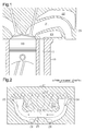
Fig. 1 is a schematic cross-sectional view showing the structure of one embodiment of a cooling structure for a cylinder head; -
Fig. 2 is a cross-sectional view showing the structure of a lower water jacket of the embodiment ofFig. 1 ; -
Fig. 3 is a cross-sectional view showing the structure of an upper water jacket of the embodiment ofFig. 1 ; -
Fig. 4 is a cross-sectional view taken along line 4-4 ofFig. 3 ; -
Fig. 5 is a cross-sectional view taken along line 5-5 ofFig. 3 ; and -
Fig. 6 is a cross-sectional view taken along line 6-6 ofFig. 3 . - One embodiment of a cooling structure for a cylinder head will now be described with reference to
Figs. 1 to 6 . - As shown in
Fig. 1 , acylinder head 20 is arranged above acylinder block 10 in an internal combustion engine. Thecylinder head 20 includes anexhaust manifold 21 that is in communication with acombustion chamber 30. Theexhaust manifold 21 is curved so that a portion at a downstream side of the exhaust is located below a portion at an upstream side of the exhaust, which is at the side of thecombustion chamber 30. Thecylinder head 20 includes anupper water jacket 22, which is arranged above theexhaust manifold 21 and serves as a first water jacket, and alower water jacket 23, which is arranged below theexhaust manifold 21 and serves as a second water jacket. Thelower water jacket 23 is in communication with acoolant passage 11 formed in thecylinder block 10. - The structure of each of the
upper water jacket 22 and thelower water jacket 23 will now be described with reference toFigs. 2 to 6 . - As shown in
Fig. 2 , theexhaust manifold 21 includes a plurality ofbranches 211, which are connected to thecombustion chambers 30, and acollector 212. Thebranches 211 converge into thecollector 212. Thelower water jacket 23 extends in a direction in which cylinders are arranged (left-right direction in the drawing) and covers thecollector 212 of theexhaust manifold 21 from a lower side. An area in which thelower water jacket 23 covers theexhaust manifold 21 is set to be 40% or less of the surface area of a lower portion of theexhaust manifold 21. Theexhaust manifold 21, which is indicated by broken lines, includes a plurality of ends that are located below the lower water jacket 23 (located toward the cylinder block 10). - The
lower water jacket 23 includes a first end and a second end in the cylinder arrangement direction (left-right direction inFig. 2 ). The first end includes afirst inlet 24 to which a coolant is supplied from thecylinder block 10. The second end includes asecond communication passage 25 that is in communication with theupper water jacket 22. Thus, the coolant, which is supplied to thelower water jacket 23 from thefirst inlet 24, flows in the cylinder arrangement direction and is supplied to theupper water jacket 22 through thesecond communication passage 25. - The
upper water jacket 22 will now be described with reference toFig. 3 . - As shown in
Fig. 3 , theupper water jacket 22 extends in the cylinder arrangement direction (left-right direction inFig. 3 ) and covers the substantiallyentire exhaust manifold 21 including thecollector 212 from an upper side. The area in which theupper water jacket 22 covers theexhaust manifold 21 is set to be 70% or more of the surface area of an upper portion of theexhaust manifold 21. Thus, the area of theexhaust manifold 21 covered by theupper water jacket 22 is set to be larger than that covered by thelower water jacket 23. - The
upper water jacket 22 includes a first end and a second end in the cylinder arrangement direction. The first end includes asecond inlet 26 to which the coolant is supplied from thecoolant passage 11 of thecylinder block 10. The second end is connected to thesecond communication passage 25 through which the coolant is supplied from thelower water jacket 23. The second end also includes acoolant outlet 27 that connects theupper water jacket 22 to the exterior. Thus, the coolant, which is supplied to theupper water jacket 22 from thesecond inlet 26 and thesecond communication passage 25, flows toward thecoolant outlet 27 and is discharged from thecoolant outlet 27 to, for example, a radiator arranged at an outer side. - As described above, in each of the
water jackets first inlet 24 or thesecond inlet 26, corresponds to an upstream side end in a flow direction of the coolant. The second end, which includes thesecond communication passage 25, corresponds to a downstream side end in the flow direction of the coolant. -
Fig. 4 is a cross-sectional view taken along line 4-4 ofFig. 3 . - As shown in
Fig. 4 , thesecond inlet 26 of theupper water jacket 22 is in communication with thefirst inlet 24 of thelower water jacket 23. Thefirst inlet 24 is in communication with thecoolant passage 11 of thecylinder block 10. Thus, the coolant is supplied from thecoolant passage 11 to each of thewater jackets inlets - Further, as shown in
Figs. 2 and3 , thewater jackets first communication passage 28 and athird communication passage 29. The coolant is supplied from thelower water jacket 23 to theupper water jacket 22 through thefirst communication passage 28 and thethird communication passage 29 in addition to thesecond communication passage 25. Thefirst communication passage 28 is located at an upstream side of thecollector 212 in the flow direction of the coolant and arranged at a position that is the most proximate to thecollector 212. Thethird communication passage 29 is located at a downstream side of thecollector 212 in the flow direction of the coolant and arranged at a position where the distance from thethird communication passage 29 to thecollector 212 is substantially the same as the distance from thefirst communication passage 28 to thecollector 212. -
Fig. 5 is a cross-sectional view taken along line 5-5 ofFig. 3 . - As shown in
Fig. 5 , thefirst communication passage 28 connects the twowater jackets collector 212. Thethird communication passage 29 connects the twowater jackets collector 212. That is, thecollector 212 is located between thefirst communication passage 28 and thethird communication passage 29. Thus, theupper water jacket 22, thefirst communication passage 28, and thethird communication passage 29 are arranged to surround an upper side and two opposite sides of thecollector 212. - The
second communication passage 25 will now be described with reference toFig. 6. Fig. 6 is a cross-sectional view taken along line 6-6 ofFig. 3 . - As shown in
Fig. 6 , thesecond communication passage 25 includes an upstream side opening 251 that opens to thelower water jacket 23 and adownstream side opening 252 that opens to theupper water jacket 22. The entiresecond communication passage 25 is inclined relative to the vertical direction (up-down direction in the drawing) so that thedownstream side opening 252 is located closer to a side of thecoolant outlet 27 than the upstream side opening 251 as viewed from the vertical direction (up-down direction in the drawing). More specifically, a coolant flow passage direction of thedownstream side opening 252 extends toward thecoolant outlet 27. The cross-sectional passage area S2 of thesecond communication passage 25 is set to be smaller than the cross-sectional passage area S1 (Fig. 5 ) of thefirst communication passage 28. - The operation of the cooling structure for the
cylinder head 20, which is configured in the above manner, will now be described. - Exhaust constantly flows to the
collector 212 of theexhaust manifold 21 from one of thebranches 211. Thus, thecollector 212 tends to have a high temperature due to heat of the exhaust. Theexhaust manifold 21 is curved so that the downstream side portion is located below the upstream side portion. Thus, the exhaust flowing to theexhaust manifold 21 from thecombustion chamber 30 tends to strike an upper portion of an inner wall of theexhaust manifold 21. This causes the upper portion of theexhaust manifold 21 to have a high temperature compared to a lower portion. More specifically, in theexhaust manifold 21, thecollector 212, particularly, an upper portion of thecollector 212, tends to have a high temperature. - As indicated by arrows of
Fig. 2 , in the present embodiment, when a coolant is supplied from thecylinder block 10 to thelower water jacket 23 through thefirst inlet 24 and flows toward thesecond communication passage 25, some of the coolant is supplied to theupper water jacket 22 from thefirst communication passage 28 and thethird communication passage 29. In this case, the cross-sectional passage area S2 of thesecond communication passage 25 is set to be smaller than the cross-sectional passage area S1 of thefirst communication passage 28. Thus, more coolant is supplied to theupper water jacket 22 through thefirst communication passage 28 than when a different setting is used. This increases a flow rate of the coolant flowing to a portion of theupper water jacket 22 that covers the upper portion of thecollector 212. - As described above, the upper portion of the
exhaust manifold 21 tends to have a high temperature compared to the lower portion. In this regard, in the present embodiment, the area of theexhaust manifold 21 covered by theupper water jacket 22 is larger than the area of theexhaust manifold 21 covered by thelower water jacket 23. This increases the amount of the coolant flowing above theexhaust manifold 21 compared to the amount of the coolant flowing to thelower water jacket 23. - The
cylinder head 20 is configured so that thecollector 212 of theexhaust manifold 21 is located between thefirst communication passage 28 and thethird communication passage 29. Thus, the coolant is supplied through thefirst communication passage 28 and thethird communication passage 29 to a portion that covers the two opposite sides of thecollector 212. - In the
second communication passage 25, the flow passage direction of thedownstream side opening 252, which opens to theupper water jacket 22, extends toward thecoolant outlet 27. Thus, when flowing to theupper water jacket 22 from thesecond communication passage 25, the coolant flows toward thecoolant outlet 27. This generates flow of the coolant toward thecoolant outlet 27 in theupper water jacket 22. Consequently, more coolant is discharged to the exterior from thecoolant outlet 27. This increases the amount of the coolant flowing through each of thewater jackets - The embodiment, which has been described above, has the advantages described below.
- (1) The present embodiment increases the flow rate of the coolant flowing to the portion of the
upper water jacket 22 that covers the upper portion of thecollector 212. This effectively cools the upper portion of thecollector 212. - (2) The present embodiment effectively cools the upper portion of the
exhaust manifold 21, which tends to have a high temperature, while limiting excessive cooling of the lower portion of theexhaust manifold 21. - (3) In the present embodiment, the coolant is supplied through the
first communication passage 28 and thethird communication passage 29 to a portion that covers the two opposite sides of thecollector 212. This effectively cools not only the upper portion of thecollector 212 but also the sides of thecollector 212. - (4) The present embodiment increases the amount of the coolant flowing through each of the
water jackets exhaust manifold 21. - The embodiment may be modified as follows.
- In the embodiment, the area of the
exhaust manifold 21 covered by thelower water jacket 23 is set to be 40% or less of the surface area of the lower portion of theexhaust manifold 21. The area of theexhaust manifold 21 covered by theupper water jacket 22 is set to be 70% or more of the surface area of the upper portion of theexhaust manifold 21. However, the condition for the setting may be modified in accordance with various conditions, such as the degree of overheating of theexhaust manifold 21. - In each embodiment, the
third communication passage 29 is located at the downstream side of thecollector 212 and arranged at the position where the distance from thethird communication passage 29 to thecollector 212 is substantially the same as the distance from thefirst communication passage 28 to thecollector 212. However, the distance from thethird communication passage 29 to thecollector 212 may be modified as long as the sides of thecollector 212 can be cooled. - In each embodiment, the entire
second communication passage 25 is inclined relative to the vertical direction so that thedownstream side opening 252 is located closer to the side of thecoolant outlet 27 than the upstream side opening 251 as viewed from the vertical direction. However, the flow passage direction may extend toward thecoolant outlet 27 by inclining only thedownstream side opening 252 or attaching another member to the interior of thedownstream side opening 252. The flow passage direction of thedownstream side opening 252, which opens to theupper water jacket 22, only needs to extend toward thecoolant outlet 27. - In each embodiment, in at least one of the
first communication passage 28, thethird communication passage 29, and thesecond inlet 26, the flow passage direction of a portion that opens to theupper water jacket 22 may extend toward thecoolant outlet 27. - In each embodiment, in the
second communication passage 25, the flow passage direction of thedownstream side opening 252, which opens to theupper water jacket 22, is set to extend toward thecoolant outlet 27. However, this configuration may be omitted. Advantages (1) to (3) described above may be obtained even when this configuration is omitted. - The
third communication passage 29 may be omitted from each embodiment. Advantages (1), (2), and (4) described above may be obtained even in a configuration in which thethird communication passage 29 is omitted. - In each embodiment, when the temperature of the upper portion of the
exhaust manifold 21 is not that high compared to the temperature of the lower portion, the area of theexhaust manifold 21 covered by theupper water jacket 22 may be set to be substantially the same as the area of theexhaust manifold 21 covered by thelower water jacket 23. Advantages (1), (3), and (4) described above may be obtained even when the above setting is used. -
- 10
- cylinder block
- 11
- coolant passage
- 20
- cylinder head
- 21
- exhaust manifold
- 22
- upper water jacket
- 23
- lower water jacket
- 24
- first inlet
- 25
- second communication passage
- 26
- second inlet
- 27
- coolant outlet
- 28
- first communication passage
- 29
- third communication passage
- 30
- combustion chamber
- 211
- branch
- 212
- collector
- 251
- upstream side opening
- 252
- downstream side opening
Claims (4)
- A cooling structure for a cylinder head comprising in the cylinder head:an exhaust manifold that includes a plurality of branches and a collector, wherein the branches are respectively connected to combustion chambers of cylinders, and the branches converge at the collector;a first water jacket located above the exhaust manifold, wherein the first water jacket covers the exhaust manifold including at least the collector;a second water jacket located below the exhaust manifold, wherein the second water jacket covers the exhaust manifold including at least the collector;a plurality of communication passages that supply coolant from the second water jacket to the first water jacket; anda coolant outlet that connects the first water jacket to the exterior, wherein
the cooling structure for the cylinder head is configured so that the coolant flows from each water jacket in a direction in which the cylinders are arranged in order to be discharged out of the coolant outlet,
the communication passages includea first communication passage located at an upstream side of the collector in a flow direction of the coolant and arranged at a position that is the most proximate to the collector, anda second communication passage located in a downstream side end of each water jacket, anda cross-sectional passage area of the second communication passage is set to be smaller than a cross-sectional passage area of the first communication passage. - The cooling structure for a cylinder head according to claim 1, wherein the first water jacket is set so that an area of the exhaust manifold that is covered by the first water jacket is larger than an area of the exhaust manifold that is covered by the second water jacket.
- The cooling structure for a cylinder head according to claim 1 or 2, wherein
the communication passages include a third communication passage located at a downstream side of the collector in the flow direction of the coolant, and
the collector is located between the third communication passage and the first communication passage. - The cooling structure for a cylinder head according to any one of claims 1 to 3, wherein
the second communication passage includes a downstream side opening that opens to the first water jacket, and
the second communication is configured so that a flow passage direction of the downstream side opening extends toward the coolant outlet.
Applications Claiming Priority (2)
| Application Number | Priority Date | Filing Date | Title |
|---|---|---|---|
| JP2012235787A JP5729367B2 (en) | 2012-10-25 | 2012-10-25 | Cylinder head cooling structure |
| PCT/JP2013/075674 WO2014065057A1 (en) | 2012-10-25 | 2013-09-24 | Cooling structure for cylinder head |
Publications (2)
| Publication Number | Publication Date |
|---|---|
| EP2913507A1 true EP2913507A1 (en) | 2015-09-02 |
| EP2913507A4 EP2913507A4 (en) | 2015-11-18 |
Family
ID=50544437
Family Applications (1)
| Application Number | Title | Priority Date | Filing Date |
|---|---|---|---|
| EP13849755.7A Ceased EP2913507A4 (en) | 2012-10-25 | 2013-09-24 | COOLING STRUCTURE OF A CYLINDER HEAD |
Country Status (5)
| Country | Link |
|---|---|
| US (1) | US9562493B2 (en) |
| EP (1) | EP2913507A4 (en) |
| JP (1) | JP5729367B2 (en) |
| CN (1) | CN104736826B (en) |
| WO (1) | WO2014065057A1 (en) |
Families Citing this family (12)
| Publication number | Priority date | Publication date | Assignee | Title |
|---|---|---|---|---|
| JP3349080B2 (en) | 1997-11-20 | 2002-11-20 | 株式会社椿本チエイン | Linear motor driven sorting device |
| EP3081795B1 (en) * | 2013-12-09 | 2020-02-26 | Mitsubishi Jidosha Kogyo Kabushiki Kaisha | Cylinder head for engine |
| JP6347479B2 (en) * | 2014-03-27 | 2018-06-27 | ダイハツ工業株式会社 | Internal combustion engine and cylinder head thereof |
| JP6131920B2 (en) * | 2014-07-28 | 2017-05-24 | トヨタ自動車株式会社 | Internal combustion engine cooling structure |
| AT517127B1 (en) * | 2015-05-07 | 2019-12-15 | Avl List Gmbh | CYLINDER HEAD FOR AN INTERNAL COMBUSTION ENGINE |
| DE102015222859A1 (en) * | 2015-11-19 | 2017-05-24 | ŠKODA AUTO a.s. | Cylinder head of an internal combustion engine with integrated exhaust manifold and cooling jacket |
| US10087894B2 (en) * | 2016-03-03 | 2018-10-02 | Ford Global Technologies, Llc | Cylinder head of an internal combustion engine |
| JP6496288B2 (en) * | 2016-09-13 | 2019-04-03 | 本田技研工業株式会社 | Vehicle charging unit arrangement structure |
| JP2018091260A (en) * | 2016-12-06 | 2018-06-14 | 本田技研工業株式会社 | Cooling structure of internal combustion engine |
| JP7200863B2 (en) * | 2019-07-17 | 2023-01-10 | トヨタ自動車株式会社 | cylinder head |
| KR102781211B1 (en) | 2020-02-06 | 2025-03-12 | 엘지전자 주식회사 | Air conditioner and method for controlling for the same |
| KR20220031324A (en) * | 2020-09-04 | 2022-03-11 | 현대자동차주식회사 | Cylinder head |
Family Cites Families (21)
| Publication number | Priority date | Publication date | Assignee | Title |
|---|---|---|---|---|
| JPS56157344U (en) * | 1980-04-25 | 1981-11-24 | ||
| JPH0296449A (en) | 1988-09-30 | 1990-04-09 | Fujitsu Ltd | Originating party name automatic displaying system for telephone terminal |
| JPH0296449U (en) * | 1989-01-18 | 1990-08-01 | ||
| JP3155993B2 (en) * | 1992-12-11 | 2001-04-16 | ヤマハ発動機株式会社 | Cylinder head cooling structure for multi-valve engine |
| JP2753787B2 (en) * | 1993-01-22 | 1998-05-20 | 株式会社クボタ | Cylinder head for water-cooled multi-cylinder diesel engine |
| US7051685B2 (en) * | 2003-10-27 | 2006-05-30 | General Motors Corporation | Cylinder head with integrated exhaust manifold |
| JP4098712B2 (en) | 2003-12-25 | 2008-06-11 | 本田技研工業株式会社 | Exhaust manifold integrated engine cooling structure |
| JP2007162519A (en) * | 2005-12-12 | 2007-06-28 | Nissan Motor Co Ltd | Cylinder head cooling structure |
| US7367294B2 (en) * | 2006-03-14 | 2008-05-06 | Gm Global Technology Operations, Inc. | Cylinder head with integral tuned exhaust manifold |
| JP2007278065A (en) | 2006-04-03 | 2007-10-25 | Nissan Motor Co Ltd | Exhaust manifold integrated cylinder head cooling structure |
| EP2003320B1 (en) * | 2007-06-13 | 2017-10-11 | Ford Global Technologies, LLC | Cylinder head for an internal combustion engine |
| JP5130825B2 (en) * | 2007-08-16 | 2013-01-30 | トヨタ自動車株式会社 | Cylinder head of internal combustion engine |
| JP4983556B2 (en) * | 2007-11-08 | 2012-07-25 | トヨタ自動車株式会社 | Internal combustion engine cooling structure |
| US7784442B2 (en) * | 2007-11-19 | 2010-08-31 | Gm Global Technology Operations, Inc. | Turbocharged engine cylinder head internal cooling |
| KR100916773B1 (en) * | 2007-12-12 | 2009-09-14 | 현대자동차주식회사 | Port-Exhaust Manifold Integrated Cylinder Head |
| EP2172635B1 (en) | 2008-10-02 | 2018-12-12 | Ford Global Technologies, LLC | Cylinder head for an internal combustion engine with two integrated exhaust manifolds and method to operate an internal combustion engine with such a cylinder head |
| JP2010275915A (en) * | 2009-05-28 | 2010-12-09 | Nissan Motor Co Ltd | Cooling device for internal combustion engine |
| JP5595079B2 (en) | 2010-03-25 | 2014-09-24 | ダイハツ工業株式会社 | Cylinder head water jacket structure |
| EP2388463B1 (en) * | 2010-05-17 | 2012-05-16 | Fiat Powertrain Technologies S.p.A. | Cylinder head for an internal combustion engine, with integrated exhaust manifold |
| US8474251B2 (en) * | 2010-10-19 | 2013-07-02 | Ford Global Technologies, Llc | Cylinder head cooling system |
| EP2500558B1 (en) * | 2011-03-10 | 2017-02-15 | Fiat Powertrain Technologies S.p.A. | Cylinder head for an internal combustion engine, with integrated exhaust manifold and subgroups of exhaust conduits merging into manifold portions which are superimposed and spaced apart from each other |
-
2012
- 2012-10-25 JP JP2012235787A patent/JP5729367B2/en active Active
-
2013
- 2013-09-24 CN CN201380055145.5A patent/CN104736826B/en not_active Expired - Fee Related
- 2013-09-24 WO PCT/JP2013/075674 patent/WO2014065057A1/en not_active Ceased
- 2013-09-24 EP EP13849755.7A patent/EP2913507A4/en not_active Ceased
- 2013-09-24 US US14/433,740 patent/US9562493B2/en not_active Expired - Fee Related
Also Published As
| Publication number | Publication date |
|---|---|
| JP5729367B2 (en) | 2015-06-03 |
| WO2014065057A1 (en) | 2014-05-01 |
| US9562493B2 (en) | 2017-02-07 |
| EP2913507A4 (en) | 2015-11-18 |
| JP2014084828A (en) | 2014-05-12 |
| CN104736826B (en) | 2016-12-14 |
| CN104736826A (en) | 2015-06-24 |
| US20150247473A1 (en) | 2015-09-03 |
Similar Documents
| Publication | Publication Date | Title |
|---|---|---|
| US9562493B2 (en) | Cooling structure for cylinder head | |
| US8960137B2 (en) | Integrated exhaust cylinder head | |
| RU129154U1 (en) | ENGINE COOLING SYSTEM WITH CYLINDER HEAD INTEGRATED WITH EXHAUST SYSTEM (OPTIONS) | |
| US9359058B1 (en) | Outboard marine propulsion devices and methods of making outboard marine propulsion devices having exhaust runner cooling passages | |
| US9732708B2 (en) | Internal combustion engine | |
| JP4983556B2 (en) | Internal combustion engine cooling structure | |
| US20140202143A1 (en) | Cylinder head | |
| CN105626296B (en) | Cylinder head having water jacket integrally formed with exhaust manifold | |
| JP2009002265A (en) | Internal combustion engine cooling structure | |
| CN110366636B (en) | Cylinder head for an internal combustion engine | |
| EP3342999B1 (en) | Water-cooled engine | |
| US10634088B2 (en) | Coolant jacket for a liquid-cooled cylinder head | |
| JP2016173107A (en) | Cylinder head for an internal combustion engine having a cooling channel | |
| US20060254272A1 (en) | Cylinder head and combustion engine comprising a cylinder head | |
| EP2826975B1 (en) | Engine and saddle type vehicle | |
| US10227947B2 (en) | Cylinder head for vehicle engine | |
| KR20180039777A (en) | Water jacket of cylinder head | |
| JP4363176B2 (en) | Engine exhaust gas recirculation system | |
| JP6303870B2 (en) | Internal combustion engine cylinder block | |
| JP6696125B2 (en) | Cylinder head cooling structure | |
| US10107181B2 (en) | Internal combustion engine | |
| JP6040658B2 (en) | Cooling device for internal combustion engine | |
| JP4587070B2 (en) | Turbocharged engine | |
| JP6327059B2 (en) | Internal combustion engine | |
| JP2017190731A (en) | Cylinder head for engine |
Legal Events
| Date | Code | Title | Description |
|---|---|---|---|
| PUAI | Public reference made under article 153(3) epc to a published international application that has entered the european phase |
Free format text: ORIGINAL CODE: 0009012 |
|
| 17P | Request for examination filed |
Effective date: 20150410 |
|
| AK | Designated contracting states |
Kind code of ref document: A1 Designated state(s): AL AT BE BG CH CY CZ DE DK EE ES FI FR GB GR HR HU IE IS IT LI LT LU LV MC MK MT NL NO PL PT RO RS SE SI SK SM TR |
|
| AX | Request for extension of the european patent |
Extension state: BA ME |
|
| RA4 | Supplementary search report drawn up and despatched (corrected) |
Effective date: 20151015 |
|
| RIC1 | Information provided on ipc code assigned before grant |
Ipc: F02F 1/40 20060101ALI20151009BHEP Ipc: F02F 1/42 20060101ALN20151009BHEP Ipc: F02F 1/38 20060101AFI20151009BHEP Ipc: F02F 1/36 20060101ALI20151009BHEP |
|
| DAX | Request for extension of the european patent (deleted) | ||
| 17Q | First examination report despatched |
Effective date: 20160811 |
|
| REG | Reference to a national code |
Ref country code: DE Ref legal event code: R003 |
|
| 18R | Application refused |
Effective date: 20180423 |