EP2913461B1 - Sicherheitsvorrichtung für ein zylinderschloss - Google Patents
Sicherheitsvorrichtung für ein zylinderschloss Download PDFInfo
- Publication number
- EP2913461B1 EP2913461B1 EP15155381.5A EP15155381A EP2913461B1 EP 2913461 B1 EP2913461 B1 EP 2913461B1 EP 15155381 A EP15155381 A EP 15155381A EP 2913461 B1 EP2913461 B1 EP 2913461B1
- Authority
- EP
- European Patent Office
- Prior art keywords
- slider
- cam
- security device
- opening
- locking position
- Prior art date
- Legal status (The legal status is an assumption and is not a legal conclusion. Google has not performed a legal analysis and makes no representation as to the accuracy of the status listed.)
- Active
Links
Images


Classifications
-
- E—FIXED CONSTRUCTIONS
- E05—LOCKS; KEYS; WINDOW OR DOOR FITTINGS; SAFES
- E05B—LOCKS; ACCESSORIES THEREFOR; HANDCUFFS
- E05B17/00—Accessories in connection with locks
- E05B17/14—Closures or guards for keyholes
- E05B17/145—Closures or guards for keyholes with combination lock
-
- E—FIXED CONSTRUCTIONS
- E05—LOCKS; KEYS; WINDOW OR DOOR FITTINGS; SAFES
- E05B—LOCKS; ACCESSORIES THEREFOR; HANDCUFFS
- E05B17/00—Accessories in connection with locks
- E05B17/14—Closures or guards for keyholes
- E05B17/18—Closures or guards for keyholes shaped as lids or slides
- E05B17/186—Closures or guards for keyholes shaped as lids or slides sliding
-
- E—FIXED CONSTRUCTIONS
- E05—LOCKS; KEYS; WINDOW OR DOOR FITTINGS; SAFES
- E05B—LOCKS; ACCESSORIES THEREFOR; HANDCUFFS
- E05B47/00—Operating or controlling locks or other fastening devices by electric or magnetic means
- E05B47/0038—Operating or controlling locks or other fastening devices by electric or magnetic means using permanent magnets
- E05B47/0042—Operating or controlling locks or other fastening devices by electric or magnetic means using permanent magnets with rotary magnet tumblers
-
- E—FIXED CONSTRUCTIONS
- E05—LOCKS; KEYS; WINDOW OR DOOR FITTINGS; SAFES
- E05B—LOCKS; ACCESSORIES THEREFOR; HANDCUFFS
- E05B47/00—Operating or controlling locks or other fastening devices by electric or magnetic means
- E05B47/0038—Operating or controlling locks or other fastening devices by electric or magnetic means using permanent magnets
- E05B47/0045—Operating or controlling locks or other fastening devices by electric or magnetic means using permanent magnets keys with permanent magnets
Definitions
- the present invention is relative to a security device for a cylinder lock, in particular for doors or gates, designed for preventing attempts at tampering with the lock, breaking or vandalizing it.
- Cylinder locks suitable for example to allow the closure and opening of a door or gate comprise a cylinder that is operated through a relative key inserted into a keyhole formed axially with respect to the cylinder.
- Cylinder locks of known type are generally made of brass, a material that offers scarce mechanical resistance against forcing attempts carried out by drilling and/or breaking and/or wrenching.
- a known means of protecting the cylinder lock from possible break-ins is to mount on the cylinder lock a covering element arranged so as to cover the cylinder and consisting of a circular escutcheon plate that is provided, at the keyhole, with a round hole in which is rotatably associated a keyhole guard disk provided with a slit that allows the insertion of the key.
- Italian Patent IT 1342717 on which the preamble of claim 1 is based, describes a security device for a cylinder lock that includes a base plate of essentially rectangular shape at one end of which is formed a through opening in which is inserted the portion of the cylinder projecting from the lock.
- each cam On the lateral surface of each cam is radially formed an undercut that can be engaged with a respective locking pin housed slidingly in a through duct formed transversally to the base plate and communicating with the seat of the respective cam.
- Each pin is urged externally in the respective duct by a spring inserted in the duct.
- a cover element capable of selectively occluding the lock cylinder.
- suitable slots engageable with the pins protruding from the base plate when the covering element completely occludes the cylinder; in this manner, the sliding of the covering element with respect to the base plate is blocked.
- the unlocking of the covering element is made possible by placing on the same a relative magnetic key containing magnets capable of coupling with the magnets contained in the cams to cause the rotation of these cams until the circumferential undercuts are brought into a position of axial alignment with the pins.
- the lowering of the covering element causes the pins to exit from the side slots and to enter into the undercuts of the cams, so as to allow the covering element to slide downward with respect to the base plate and make the cylinder accessible for inserting the key for opening the door.
- the security device described above provides a greater protection with respect to the conventional escutcheons with keyhole guards, it has however some drawbacks.
- the dimensions of the device, and particularly its considerable vertical extension, in addition to making it aesthetically unattractive may cause sticking or jamming during the sliding of the covering element
- the positioning of the covering element outside the base plate, and thus in a visible position on the external side of the door on which the device is installed makes it easily susceptible to attacks and possible actions of tampering, breaking-in and vandalism, for example by being hit with mallet blows to forcibly lower the covering element or by drilling it with a drill bit so as to access the cylinder, even when the covering element is a the locked position.
- WO 2007/088765 discloses a security device adapted to be coupled to a cylinder lock comprising :
- WO 03/025316 discloses a protector of cylinder lock for vehicle in which a shutter plate acting between a position for closing an insertion hole corresponding to the key hole of a cylinder lock and a position for opening the insertion hole is contained in a casing, and a magnet lock allowing action of the shutter plate from the closing position to the opening position when a magnet key is fitted in a fitting recess is disposed on the casing.
- the insertion hole is eccentrically arranged in respect to the casing and the key hole is eccentrically arranged in respect to the center of the key plate.
- the main objective of the present invention is thus to devise a security device of a cylinder lock capable of overcoming the disadvantages of the prior art.
- one purpose of the present invention is to provide a security device for a cylinder lock provided with a greater capacity to withstand break-in attempts, tampering or vandalism.
- Another purpose of the present invention is to provide a device that combines in a single structure the functions of protecting or shielding the cylinder.
- a further purpose of the present invention is to provide a security device having a more compact structure, both to guarantee a more reliable operation and a more attractive aesthetic appearance.
- Yet another purpose is to realize a device in which the locking and unlocking operations performed by the user can be carried out more easily.
- One not least important purpose is to realize a security device for a cylinder lock that achieves the above objective and purposes at competitive costs and that can be created with the usual well-known machines, systems and equipment.
- reference numeral 1 indicates a security device for a cylinder lock 100 ( fig. 7a ) applicable, for example, to a door 200.
- the device comprises a basic body, or casing 2, of essentially cylindrical shape associable to the lock 100 and provided with a first axial opening 3 for inserting a cylinder (not shown in the enclosed figures).
- the first opening 3 is arranged in an eccentric position with respect to the casing 2.
- a key-hole guard disk 4 can be advantageously provided rotatably associable to the casing 2 at a recessed circumferential portion 5 arranged along at least an edge portion of the first opening 3.
- the key-hole guard disk 4 is provided with a slit 6 to allow the insertion of the stem of a relative key 300 into the cylinder lock 100.
- a protective key-plate 7 is adapted to be coupled to the casing 2 from the side opposite the direction of insertion of the cylinder so that, when in use, it is arranged on the outward-facing side of the door 200.
- the protective key-plate 7 is provided with a second through-opening 8 arranged eccentrically with respect to the centre of the key-plate 7 so that, when the device is installed, said second opening 8 is preferably substantially aligned coaxially with the first opening 3 of the casing 2 and, if present, with the key-hole guard disk 4.
- a cavity 10 having a substantially rectilinear extension and arranged substantially parallel to the medial axis passing through the second opening 8 and the protective key-plate 7.
- guiding means 11, 12 consisting for example of a first portion 11 on one side of the cavity 10 and of a second portion 12 on the opposite side, both lowered with respect to the inner surface 9 of the protective key-plate 7 facing the casing 2.
- the cavity 10 or, if present, the guiding means 11, 12, have, at least on one side, and preferably on each side of its longitudinal extension, abutting means, whose function will be better explained later, comprising, on one side, at least a first slot 13 and a second slot 14 and advantageously, on the opposite side, at least a third slot 15 and a fourth slot 16.
- the pair formed by the first slot 13 and by the second slot 14 is arranged offset with respect to the pair formed by the third slot 15 and by the fourth slot 16.
- the first slot 13 is arranged near the end of the cavity 10 adjacent to the second opening 8 and the second slot 14 in an intermediate section; on the opposite side, the third slot 15 is arranged in an intermediate section of the cavity 10 and the fourth slot 16 near the opposite end of the cavity 10 with respect to the second opening 8.
- the walls of the cavity 10, or the first recessed portion 11 and the second recessed portion 12, are joined near the respective slots 13, 14, 15, 16 through an inclined plane or a radiused section.
- a slider 17 is slidingly accommodated within the cavity 10 and is movable between a locking position ( figures 3a, 4a, 4b , 7a ), in which the slider 17 closes the second opening 8 so as to occlude the cylinder lock 100 and prevent access to it through the first opening 3 and the slit 6, if any, on the key-hole guard disk 4, and an unlocking position ( figures 3c, 5a, 5b , 7c ), in which the slider 17 clears the passage through the second opening 8 to allow the user to insert the stem of the key 300 into the cylinder through the slit 6 and the opening 3.
- a combinatory unit of magnetic type is adapted to be housed in the slider 17 so that it will be jointly movable with the slider 17.
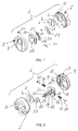
- the combinatory unit comprises at least a cam, preferably two cams 20, 21, in each of which are housed magnetic means 22, 23; the rotation of the cams, driven by a magnetic actuator 36 as will be better explained later, allows the slider 17 to slide or blocks it through suitable blocking means 30, 31 controlled by the cams 20, 21.
- the blocking means 30, 31 engage the abutting means, comprising at least the slots 13, 14 and/or 15, 16 to stably block the slider in said positions.
- the slider 17 is provided with at least a first seat 18 and a second seat 19, essentially of circular shape and arranged offset with respect to each other, adapted to rotatably accommodate the first cam 20 and the second cam 21.
- the slider 17 will of consequence be provided with a single seat.
- first magnetic means 22 and in the second cam 21 are accommodated second magnetic means 23;
- the first and the second magnetic means 22, 23 may include at least one magnet on each cam, of opposite polarity, or two magnets of opposite polarity S-N on the first cam 20 and as many oppositely polarized magnets in the second cam 21, or, again, two magnets of the same polarity S-S on the first cam 20 and two magnets of the same polarity, opposite to the previous one, N-N on the second cam 21.
- the configuration of the magnets must be such that, in the end locking and unlocking positions of the slider 17, a magnet housed in the first cam 20 faces the oppositely polarized magnet housed in the second cam 21, as exemplified in figures 3a and 3c .
- each cam 20 21 is formed a respective first notch 24 and a second notch 25.
- a pair of washers 26, 27 is advantageously provided to hold and cover the first cam 20 and the second cam 21 in the respective seats 18, 19.
- first conduit 28 and a second conduit 29 are formed, on the respective sides, a first conduit 28 and a second conduit 29 arranged axially offset from each other and communicating, respectively, with the first seat 18 and the second seat 19 at approximately their respective transversal axes.
- the conduits 28, 29 are suitable to slidably accommodate the slider 17 blocking means, comprising a respective first pin 30 and second pin 31, whose sliding movement is opposed by elastic means such as a respective first spring 32 and second spring 33 biased against suitable abutments 34, 35 provided in the conduits 28, 29.
- the movement of the slider 17 from the locking position to the unlocking position, and vice versa, is achieved through a magnetic actuator 36 provided with a suitable combination of third magnetic means (not shown in the enclosed figures) adapted to couple with the combination defined by the first and the second magnetic means 22, 23 contained in the first and in the second cam 20, 21 to cause the rotation of the latter, as will be better explained below.
- the slider 17 is provided with a recess 37 to avoid interfering, in the unlocking position, with the second opening 8.
- the operation of the device is as follows: in the condition with the door closed with the security device actuated, and therefore with the slider 17 covering the second opening 8 from inside to prevent access to the cylinder lock ( figures 3a, 4a, 4b , 7a ), the first and the second magnetic means 22, 23 are arranged so that a magnet contained in the first cam 20 faces the magnet of opposite polarity contained in the second cam 21, as exemplified in figure 3a .
- the first spring 32 pushes the head of the first pin 30 into engagement with the first slot 13, while the opposite end of the first pin 30 presses against the cylindrical wall of the first cam 20 from a direction approximately opposite the first notch 24.
- the second spring 33 pushes the head of the second pin 31 into engagement with the third slot 15, while the opposite end of the second pin 31 presses against the cylindrical wall of the second cam 21 from a direction approximately opposite the second notch 25.
- the sliding movement of the slider 17 is blocked by the engagement of the pins 30, 31 with the respective slots 13, 15, preventing access to the cylinder and therefore to the lock.
- the specific magnetic combination preset on the actuator 36 causes the misalignment of the magnetic means 22, 23 and thus the counterclockwise rotation, with reference to figure 3b , of the first and the second cam 21, 21 so as to bring the first notch 24 into axial alignment with the first pin 30 and, correspondingly, the second notch 25 with the second pin 31.
- the springs 32, 33 thus push the respective pins 30, 31 into engagement with the notches 24, 25.
- the actuator 36 is removed and the slider 17 reaches the unlocking position, exemplified in figures 3c, 5a, 5b and 7c ; the removal of the actuator 36 causes the inverse rotation, clockwise with reference to figure 3c , of the cams 20, 21, which return to the initial position with the first magnetic means 22 aligned with the second magnetic means 23 by effect of the magnetic attraction between magnets of opposite polarities.
- the ends of the pins 30, 31 become disengaged from the respective notches 24, 25 and, pushed by the action of the springs 32, 33, the heads of the first pin 30 and of the second pin 31 become engaged respectively in the second slot 14 and in the fourth slot 16.
- a security device has been designed for a cylinder lock capable of overcoming the drawbacks of the prior art, and in particular a device having a level of strength, and therefore a more effective security against break-in and tampering attempts and vandalism, resulting from the arrangement of the slider 17 and of the combination mechanism, consisting of the cams 20, 21, the magnetic means 22, 23 and the pins 30, 31, that are entirely held and protected within the structure of the same mechanism, and thus much less liable to external attacks; consequently, the structure of the device integrates and performs both the protection and shielding functions of the cylinder lock, when in the locked position.
- Another advantage of the present invention lies in the extremely compact structure of the device, obtained as a result of prearranging the combinatory unit inside the cursor 17. In this manner, it was possible to obtain a device with a more reliable operation, as being not prone to jamming or sticking and less susceptible to external agents, such as icing, in addition to having an attractive aesthetic appearance.
- the accommodation of the combinatory unit inside the slider also makes it possible to realize the advantage that, even in the event of perforation of the device in a breaking-in attempt, the slider remains locked in its position.
- a further advantage lies in the ease by the user to carry out the locking and unlocking operations, further facilitated if ramped approaches are provided near the locking and unlocking positions of the slider.
- the combinatory unit may include more than two cams, with the relative locking pins and slots, to increase the number of combinations available;
- figure 8 exemplifies a further embodiment of the security device according to the present invention, wherein is illustrated the protective key-plate 107 in which is slidably accommodated the slider 117, whose movement is controlled by a combinatory unit comprising three cams 120, 121 and 122.
Landscapes
- Lock And Its Accessories (AREA)
Claims (9)
- Sicherheitsvorrichtung, die angepasst ist, um mit einem Zylinderschloss gekoppelt zu sein, wobei die Sicherheitsvorrichtung ein im Wesentlichen zylindrisches Gehäuse (2), das mit dem Schloss verbindbar und mit einer ersten axialen Öffnung (3) versehen ist, die angepasst ist, um einen Zylinder des Schlosses aufzunehmen, wobei die erste axiale Öffnung (3) mit Bezug auf das Gehäuse (2) exzentrisch angeordnet ist, eine kombinatorische Einheit (20, 21), die eine magnetische Einrichtung (22, 23) aufweist, und einen Schieber (17) umfasst, der mit Bezug auf das Gehäuse (2) zwischen einer Verriegelungsposition, wobei der Schieber (17) die erste axiale Öffnung (3) verschließt, um bei Benutzung einen Zugriff auf den Zylinder zu verhindern, und einer Entriegelungsposition verschiebbar ist, wobei der Schieber (17) den Zugriff auf die erste axiale Öffnung (3) zulässt, wobei der Übergang zwischen der Verriegelungsposition und der Entriegelungsposition und umgekehrt durch ein magnetisches Stellelement (36) betätigt werden kann, das mit einer Kombination bereitgestellt wird, die angepasst ist, um mit der magnetischen Einrichtung (22, 23) der kombinatorischen Einheit (20, 21) zusammenzuarbeiten, wobei der Schieber (17) zwischen dem Gehäuse (2) und einer Schlüsselschutzplatte (7) angeordnet ist, die angepasst ist, um mit dem Gehäuse (2) gekoppelt zu sein, wobei die Schlüsselplatte (7) mit einer zweiten Durchgangsöffnung (8) versehen ist, die mit Bezug auf die Mitte der Schlüsselplatte (7) exzentrisch angeordnet ist, so dass die zweite Durchgangsöffnung (8) bei Benutzung mit der ersten axialen Öffnung (3) ausgerichtet ist, wobei die kombinatorische Einheit (20, 21) angepasst ist, um im Inneren aufgenommen und mit dem Schieber (17) gemeinsam bewegbar zu sein.
- Sicherheitsvorrichtung nach Anspruch 1, wobei ein bei Benutzung dem Gehäuse (2) zugewandter Hohlraum (10) an der inneren Oberfläche (9) der Schlüsselplatte (8) bereitgestellt wird, wobei der Hohlraum (10) eine im Wesentlichen lineare Verlängerung aufweist, die im Wesentlichen parallel zur mittleren Achse angeordnet ist, die durch die zweite Öffnung (8) und die Schlüsselplatte (7) führt.
- Sicherheitsvorrichtung nach Anspruch 2, wobei der Schieber (17) angepasst ist, um innerhalb des Hohlraums (10) aufgenommen zu werden, so dass er zwischen der Verriegelungsposition, wobei der Schieber (17) die zweite Öffnung (8) verschließt, und der Entriegelungsposition bewegbar ist, wobei der Schieber (17) den Durchgang durch die zweite Öffnung (8) räumt.
- Sicherheitsvorrichtung nach Anspruch 1, wobei die kombinatorische Einheit (20, 21) wenigstens einen Nocken (22, 23) umfasst, der mit dem Schieber (17) drehbar verbunden ist und die magnetische Einrichtung (22, 23) aufweist, wobei der wenigstens eine Nocken (20, 21) angepasst ist, um eine geeignete Sperrvorrichtung (30, 31) zu steuern, die angepasst ist, um es dem Schieber (17) zu ermöglichen, zwischen der Verriegelungsposition und der Entriegelungsposition zu gleiten oder um den Schieber (17) an der Verriegelungsposition oder der Entriegelungsposition zu sperren.
- Sicherheitsvorrichtung nach Anspruch 1, wobei die kombinatorische Einheit (20, 21) wenigstens einen ersten Nocken (20) und einen zweiten Nokken (21) umfasst, die mit dem Schieber (17) drehbar verbunden sind, wobei jeder von wenigstens dem ersten Nocken (20) und dem zweiten Nocken (21) wenigstens einen Magneten (22, 23) aufweist, der so polarisiert ist, dass er in der Verriegelungsposition und der Entriegelungsposition durch einen entgegengesetzt polarisierten Magneten angezogen wird, der in dem anderen Nocken enthalten ist.
- Sicherheitsvorrichtung nach Anspruch 5, wobei wenigstens ein erster Nokken (20) und ein zweiter Nocken (21) angepasst sind, um eine geeignete Sperrvorrichtung (30, 31) zu steuern, die angepasst ist, um es dem Schieber (17) zu ermöglichen, zwischen der Verriegelungsposition und der Entriegelungsposition zu gleiten oder um den Schieber (17) in der Verriegelungsposition oder der Entriegelungsposition zu sperren.
- Sicherheitsvorrichtung nach Anspruch 6, wobei die Sperrvorrichtung (30, 31) mit dem Schieber (17) verschiebbar verbunden und gegen eine elastische Einrichtung (32, 33) bewegbar ist, um so eine Gleitbewegung des Schiebers (17) zu sperren oder zu erlauben.
- Sicherheitsvorrichtung nach Anspruch 2 und 7, wobei die Sperrvorrichtung (30, 31) angepasst ist, um mit einer geeigneten Anstoßeinrichtung (13, 14, 15, 16) in Eingriff zu kommen, die in dem Hohlraum (10) bereitgestellt wird, um den Schieber (17) in der Verriegelungsposition oder der Entriegelungsposition stabil zu sperren.
- Sicherheitsvorrichtung nach Anspruch 8, wobei das magnetische Stellelement (36), das mit der magnetischen Einrichtung (22, 23) zusammenwirkt, eine Drehbewegung des ersten Nockens (20) und des zweiten Nockens (21) bewirkt, die angepasst ist, um die Sperrvorrichtung (30, 31) von der Anstoßeinrichtung (13, 14, 15, 16) zu lösen, um es so dem Schieber (17) zu ermöglichen, von der Verriegelungsposition zur Entriegelungsposition und umgekehrt zu gleiten.
Applications Claiming Priority (1)
| Application Number | Priority Date | Filing Date | Title |
|---|---|---|---|
| ITPN20140012 | 2014-02-28 |
Publications (2)
| Publication Number | Publication Date |
|---|---|
| EP2913461A1 EP2913461A1 (de) | 2015-09-02 |
| EP2913461B1 true EP2913461B1 (de) | 2016-10-12 |
Family
ID=50630934
Family Applications (1)
| Application Number | Title | Priority Date | Filing Date |
|---|---|---|---|
| EP15155381.5A Active EP2913461B1 (de) | 2014-02-28 | 2015-02-17 | Sicherheitsvorrichtung für ein zylinderschloss |
Country Status (3)
| Country | Link |
|---|---|
| EP (1) | EP2913461B1 (de) |
| ES (1) | ES2609635T3 (de) |
| PT (1) | PT2913461T (de) |
Families Citing this family (7)
| Publication number | Priority date | Publication date | Assignee | Title |
|---|---|---|---|---|
| EP3243979B1 (de) * | 2016-05-12 | 2019-02-06 | Pier Luigi Oliana | Schutzvorrichtung, insbesondere für ein schloss einer tür oder eines türflügels |
| IT201700072347A1 (it) * | 2017-06-28 | 2017-09-28 | Piero Cravero | Sistema antintrusione |
| IT201800002717A1 (it) * | 2018-02-15 | 2019-08-15 | Pier Luigi Oliana | Dispositivo perfezionato di protezione di una serratura |
| IT202200018369A1 (it) * | 2022-09-09 | 2024-03-09 | Fabbro Emanuela Dal | Dispositivo di protezione per serrature |
| IT202300017004A1 (it) * | 2023-08-09 | 2025-02-09 | Fabbro Emanuela Dal | Dispositivo di protezione per serrature. |
| IT202300024027A1 (it) * | 2023-11-14 | 2025-05-14 | Pier Luigi Oliana | Dispositivo di protezione |
| IT202400004228A1 (it) * | 2024-02-28 | 2025-08-28 | Pier Luigi Oliana | Disco di protezione per serrature. |
Citations (2)
| Publication number | Priority date | Publication date | Assignee | Title |
|---|---|---|---|---|
| WO2003025316A1 (en) * | 2001-09-14 | 2003-03-27 | Kabushiki Kaisha Honda Lock | Protector of cylinder lock for vehicle |
| WO2007088765A1 (ja) * | 2006-01-31 | 2007-08-09 | Kabushiki Kaisha Honda Lock | シリンダ錠の保護装置 |
Family Cites Families (4)
| Publication number | Priority date | Publication date | Assignee | Title |
|---|---|---|---|---|
| DE3731877A1 (de) * | 1987-09-19 | 1989-03-30 | Elstermann Juergen Dipl Ing | Schliessvorrichtung |
| AT394877B (de) * | 1990-08-22 | 1992-07-10 | Evva Werke | Zylinderschloss mit zylindergehaeuse und einem in diesem verdrehbaren zylinderkern |
| FR2919584A1 (fr) * | 2007-07-30 | 2009-02-06 | Oreal | Boitier comportant un couvercle et une base ayant des aimants interagissant |
| ITTV20110069A1 (it) * | 2011-05-20 | 2012-11-21 | Pier Luigi Oliana | Struttura di dispositivo di protezione, particolarmente per una serratura di una porta o anta. |
-
2015
- 2015-02-17 EP EP15155381.5A patent/EP2913461B1/de active Active
- 2015-02-17 ES ES15155381.5T patent/ES2609635T3/es active Active
- 2015-02-17 PT PT151553815T patent/PT2913461T/pt unknown
Patent Citations (2)
| Publication number | Priority date | Publication date | Assignee | Title |
|---|---|---|---|---|
| WO2003025316A1 (en) * | 2001-09-14 | 2003-03-27 | Kabushiki Kaisha Honda Lock | Protector of cylinder lock for vehicle |
| WO2007088765A1 (ja) * | 2006-01-31 | 2007-08-09 | Kabushiki Kaisha Honda Lock | シリンダ錠の保護装置 |
Also Published As
| Publication number | Publication date |
|---|---|
| ES2609635T3 (es) | 2017-04-21 |
| PT2913461T (pt) | 2017-01-06 |
| EP2913461A1 (de) | 2015-09-02 |
Similar Documents
| Publication | Publication Date | Title |
|---|---|---|
| EP2913461B1 (de) | Sicherheitsvorrichtung für ein zylinderschloss | |
| KR101756565B1 (ko) | 개선된 회전식 차단 장치 | |
| CN106088849B (zh) | 一种转舌锁 | |
| US3714804A (en) | Shutter structure | |
| US8800329B1 (en) | Protected bar lock assembly | |
| US11346130B1 (en) | Double lock dual action gravity latch | |
| EP2525024B1 (de) | Schutzvorrichtung für ein in einer Türplatte montiertes Zylinderschloss | |
| EP2675974A1 (de) | Austauschbarer einsteckschlosszylinder | |
| US9540847B2 (en) | Magnetically enhanced key and lock system | |
| RU2309233C2 (ru) | Предохранительный замок для домашних дверей и им подобных | |
| EP3243979B1 (de) | Schutzvorrichtung, insbesondere für ein schloss einer tür oder eines türflügels | |
| KR200460718Y1 (ko) | 안심 자물쇠 | |
| EP3527754B1 (de) | Sicherheitsvorrichtung für einen schliesszylinder | |
| GB2548224A (en) | Further improved locks and locking mechanisms | |
| RU2629860C1 (ru) | Накладка защитная для сувальдного замка | |
| AU2010217198A1 (en) | Locking mechanism, for a padlock for example, in which a shackle can be severed for luggage inspection and then relocked | |
| RU85532U1 (ru) | Электромеханическое запирающее устройство | |
| EP2532811A1 (de) | Sicherheitsschloss mit Doppelbartschloss | |
| WO2015145202A1 (en) | Door lock protection device | |
| EP2171184B1 (de) | Schloss für verstärkte türen und dergleichen | |
| JP3418708B2 (ja) | 鍵穴の防護カバー装置 | |
| US10890012B2 (en) | Lock and key therefor | |
| RU2231605C1 (ru) | Цилиндровый механизм секретности замка (варианты) | |
| RU2279518C1 (ru) | Устройство защиты замочных скважин | |
| EP3262256A1 (de) | Universalschloss mit gleitstoppmechanismus |
Legal Events
| Date | Code | Title | Description |
|---|---|---|---|
| PUAI | Public reference made under article 153(3) epc to a published international application that has entered the european phase |
Free format text: ORIGINAL CODE: 0009012 |
|
| AK | Designated contracting states |
Kind code of ref document: A1 Designated state(s): AL AT BE BG CH CY CZ DE DK EE ES FI FR GB GR HR HU IE IS IT LI LT LU LV MC MK MT NL NO PL PT RO RS SE SI SK SM TR |
|
| AX | Request for extension of the european patent |
Extension state: BA ME |
|
| 17P | Request for examination filed |
Effective date: 20151013 |
|
| RBV | Designated contracting states (corrected) |
Designated state(s): AL AT BE BG CH CY CZ DE DK EE ES FI FR GB GR HR HU IE IS IT LI LT LU LV MC MK MT NL NO PL PT RO RS SE SI SK SM TR |
|
| 17Q | First examination report despatched |
Effective date: 20160211 |
|
| GRAP | Despatch of communication of intention to grant a patent |
Free format text: ORIGINAL CODE: EPIDOSNIGR1 |
|
| INTG | Intention to grant announced |
Effective date: 20160728 |
|
| GRAS | Grant fee paid |
Free format text: ORIGINAL CODE: EPIDOSNIGR3 |
|
| GRAA | (expected) grant |
Free format text: ORIGINAL CODE: 0009210 |
|
| AK | Designated contracting states |
Kind code of ref document: B1 Designated state(s): AL AT BE BG CH CY CZ DE DK EE ES FI FR GB GR HR HU IE IS IT LI LT LU LV MC MK MT NL NO PL PT RO RS SE SI SK SM TR |
|
| REG | Reference to a national code |
Ref country code: GB Ref legal event code: FG4D |
|
| REG | Reference to a national code |
Ref country code: CH Ref legal event code: EP |
|
| REG | Reference to a national code |
Ref country code: AT Ref legal event code: REF Ref document number: 836668 Country of ref document: AT Kind code of ref document: T Effective date: 20161015 |
|
| REG | Reference to a national code |
Ref country code: IE Ref legal event code: FG4D |
|
| REG | Reference to a national code |
Ref country code: DE Ref legal event code: R096 Ref document number: 602015000450 Country of ref document: DE |
|
| REG | Reference to a national code |
Ref country code: PT Ref legal event code: SC4A Ref document number: 2913461 Country of ref document: PT Date of ref document: 20170106 Kind code of ref document: T Free format text: AVAILABILITY OF NATIONAL TRANSLATION Effective date: 20161229 |
|
| REG | Reference to a national code |
Ref country code: NL Ref legal event code: FP |
|
| REG | Reference to a national code |
Ref country code: LT Ref legal event code: MG4D |
|
| REG | Reference to a national code |
Ref country code: FR Ref legal event code: PLFP Year of fee payment: 3 |
|
| PG25 | Lapsed in a contracting state [announced via postgrant information from national office to epo] |
Ref country code: LV Free format text: LAPSE BECAUSE OF FAILURE TO SUBMIT A TRANSLATION OF THE DESCRIPTION OR TO PAY THE FEE WITHIN THE PRESCRIBED TIME-LIMIT Effective date: 20161012 |
|
| REG | Reference to a national code |
Ref country code: AT Ref legal event code: MK05 Ref document number: 836668 Country of ref document: AT Kind code of ref document: T Effective date: 20161012 |
|
| REG | Reference to a national code |
Ref country code: ES Ref legal event code: FG2A Ref document number: 2609635 Country of ref document: ES Kind code of ref document: T3 Effective date: 20170421 |
|
| PG25 | Lapsed in a contracting state [announced via postgrant information from national office to epo] |
Ref country code: NO Free format text: LAPSE BECAUSE OF FAILURE TO SUBMIT A TRANSLATION OF THE DESCRIPTION OR TO PAY THE FEE WITHIN THE PRESCRIBED TIME-LIMIT Effective date: 20170112 Ref country code: SE Free format text: LAPSE BECAUSE OF FAILURE TO SUBMIT A TRANSLATION OF THE DESCRIPTION OR TO PAY THE FEE WITHIN THE PRESCRIBED TIME-LIMIT Effective date: 20161012 Ref country code: LT Free format text: LAPSE BECAUSE OF FAILURE TO SUBMIT A TRANSLATION OF THE DESCRIPTION OR TO PAY THE FEE WITHIN THE PRESCRIBED TIME-LIMIT Effective date: 20161012 |
|
| PG25 | Lapsed in a contracting state [announced via postgrant information from national office to epo] |
Ref country code: FI Free format text: LAPSE BECAUSE OF FAILURE TO SUBMIT A TRANSLATION OF THE DESCRIPTION OR TO PAY THE FEE WITHIN THE PRESCRIBED TIME-LIMIT Effective date: 20161012 Ref country code: HR Free format text: LAPSE BECAUSE OF FAILURE TO SUBMIT A TRANSLATION OF THE DESCRIPTION OR TO PAY THE FEE WITHIN THE PRESCRIBED TIME-LIMIT Effective date: 20161012 Ref country code: IS Free format text: LAPSE BECAUSE OF FAILURE TO SUBMIT A TRANSLATION OF THE DESCRIPTION OR TO PAY THE FEE WITHIN THE PRESCRIBED TIME-LIMIT Effective date: 20170212 Ref country code: RS Free format text: LAPSE BECAUSE OF FAILURE TO SUBMIT A TRANSLATION OF THE DESCRIPTION OR TO PAY THE FEE WITHIN THE PRESCRIBED TIME-LIMIT Effective date: 20161012 Ref country code: PL Free format text: LAPSE BECAUSE OF FAILURE TO SUBMIT A TRANSLATION OF THE DESCRIPTION OR TO PAY THE FEE WITHIN THE PRESCRIBED TIME-LIMIT Effective date: 20161012 Ref country code: AT Free format text: LAPSE BECAUSE OF FAILURE TO SUBMIT A TRANSLATION OF THE DESCRIPTION OR TO PAY THE FEE WITHIN THE PRESCRIBED TIME-LIMIT Effective date: 20161012 |
|
| REG | Reference to a national code |
Ref country code: DE Ref legal event code: R097 Ref document number: 602015000450 Country of ref document: DE |
|
| PG25 | Lapsed in a contracting state [announced via postgrant information from national office to epo] |
Ref country code: SK Free format text: LAPSE BECAUSE OF FAILURE TO SUBMIT A TRANSLATION OF THE DESCRIPTION OR TO PAY THE FEE WITHIN THE PRESCRIBED TIME-LIMIT Effective date: 20161012 Ref country code: DK Free format text: LAPSE BECAUSE OF FAILURE TO SUBMIT A TRANSLATION OF THE DESCRIPTION OR TO PAY THE FEE WITHIN THE PRESCRIBED TIME-LIMIT Effective date: 20161012 Ref country code: RO Free format text: LAPSE BECAUSE OF FAILURE TO SUBMIT A TRANSLATION OF THE DESCRIPTION OR TO PAY THE FEE WITHIN THE PRESCRIBED TIME-LIMIT Effective date: 20161012 Ref country code: EE Free format text: LAPSE BECAUSE OF FAILURE TO SUBMIT A TRANSLATION OF THE DESCRIPTION OR TO PAY THE FEE WITHIN THE PRESCRIBED TIME-LIMIT Effective date: 20161012 Ref country code: CZ Free format text: LAPSE BECAUSE OF FAILURE TO SUBMIT A TRANSLATION OF THE DESCRIPTION OR TO PAY THE FEE WITHIN THE PRESCRIBED TIME-LIMIT Effective date: 20161012 |
|
| PLBE | No opposition filed within time limit |
Free format text: ORIGINAL CODE: 0009261 |
|
| STAA | Information on the status of an ep patent application or granted ep patent |
Free format text: STATUS: NO OPPOSITION FILED WITHIN TIME LIMIT |
|
| PG25 | Lapsed in a contracting state [announced via postgrant information from national office to epo] |
Ref country code: SM Free format text: LAPSE BECAUSE OF FAILURE TO SUBMIT A TRANSLATION OF THE DESCRIPTION OR TO PAY THE FEE WITHIN THE PRESCRIBED TIME-LIMIT Effective date: 20161012 Ref country code: BG Free format text: LAPSE BECAUSE OF FAILURE TO SUBMIT A TRANSLATION OF THE DESCRIPTION OR TO PAY THE FEE WITHIN THE PRESCRIBED TIME-LIMIT Effective date: 20170112 |
|
| 26N | No opposition filed |
Effective date: 20170713 |
|
| PG25 | Lapsed in a contracting state [announced via postgrant information from national office to epo] |
Ref country code: MC Free format text: LAPSE BECAUSE OF FAILURE TO SUBMIT A TRANSLATION OF THE DESCRIPTION OR TO PAY THE FEE WITHIN THE PRESCRIBED TIME-LIMIT Effective date: 20161012 |
|
| REG | Reference to a national code |
Ref country code: IE Ref legal event code: MM4A |
|
| PG25 | Lapsed in a contracting state [announced via postgrant information from national office to epo] |
Ref country code: SI Free format text: LAPSE BECAUSE OF FAILURE TO SUBMIT A TRANSLATION OF THE DESCRIPTION OR TO PAY THE FEE WITHIN THE PRESCRIBED TIME-LIMIT Effective date: 20161012 |
|
| PG25 | Lapsed in a contracting state [announced via postgrant information from national office to epo] |
Ref country code: LU Free format text: LAPSE BECAUSE OF NON-PAYMENT OF DUE FEES Effective date: 20170217 |
|
| REG | Reference to a national code |
Ref country code: FR Ref legal event code: PLFP Year of fee payment: 4 |
|
| PG25 | Lapsed in a contracting state [announced via postgrant information from national office to epo] |
Ref country code: IE Free format text: LAPSE BECAUSE OF NON-PAYMENT OF DUE FEES Effective date: 20170217 |
|
| REG | Reference to a national code |
Ref country code: CH Ref legal event code: PL |
|
| PG25 | Lapsed in a contracting state [announced via postgrant information from national office to epo] |
Ref country code: MT Free format text: LAPSE BECAUSE OF NON-PAYMENT OF DUE FEES Effective date: 20170217 |
|
| PG25 | Lapsed in a contracting state [announced via postgrant information from national office to epo] |
Ref country code: LI Free format text: LAPSE BECAUSE OF NON-PAYMENT OF DUE FEES Effective date: 20180228 Ref country code: CH Free format text: LAPSE BECAUSE OF NON-PAYMENT OF DUE FEES Effective date: 20180228 |
|
| PG25 | Lapsed in a contracting state [announced via postgrant information from national office to epo] |
Ref country code: HU Free format text: LAPSE BECAUSE OF FAILURE TO SUBMIT A TRANSLATION OF THE DESCRIPTION OR TO PAY THE FEE WITHIN THE PRESCRIBED TIME-LIMIT; INVALID AB INITIO Effective date: 20150217 |
|
| PG25 | Lapsed in a contracting state [announced via postgrant information from national office to epo] |
Ref country code: CY Free format text: LAPSE BECAUSE OF FAILURE TO SUBMIT A TRANSLATION OF THE DESCRIPTION OR TO PAY THE FEE WITHIN THE PRESCRIBED TIME-LIMIT Effective date: 20161012 |
|
| PG25 | Lapsed in a contracting state [announced via postgrant information from national office to epo] |
Ref country code: MK Free format text: LAPSE BECAUSE OF FAILURE TO SUBMIT A TRANSLATION OF THE DESCRIPTION OR TO PAY THE FEE WITHIN THE PRESCRIBED TIME-LIMIT Effective date: 20161012 |
|
| PG25 | Lapsed in a contracting state [announced via postgrant information from national office to epo] |
Ref country code: TR Free format text: LAPSE BECAUSE OF FAILURE TO SUBMIT A TRANSLATION OF THE DESCRIPTION OR TO PAY THE FEE WITHIN THE PRESCRIBED TIME-LIMIT Effective date: 20161012 |
|
| PG25 | Lapsed in a contracting state [announced via postgrant information from national office to epo] |
Ref country code: AL Free format text: LAPSE BECAUSE OF FAILURE TO SUBMIT A TRANSLATION OF THE DESCRIPTION OR TO PAY THE FEE WITHIN THE PRESCRIBED TIME-LIMIT Effective date: 20161012 |
|
| PGFP | Annual fee paid to national office [announced via postgrant information from national office to epo] |
Ref country code: NL Payment date: 20230216 Year of fee payment: 9 |
|
| PGFP | Annual fee paid to national office [announced via postgrant information from national office to epo] |
Ref country code: PT Payment date: 20230209 Year of fee payment: 9 Ref country code: GB Payment date: 20230221 Year of fee payment: 9 Ref country code: DE Payment date: 20230216 Year of fee payment: 9 Ref country code: BE Payment date: 20230216 Year of fee payment: 9 |
|
| P01 | Opt-out of the competence of the unified patent court (upc) registered |
Effective date: 20230522 |
|
| REG | Reference to a national code |
Ref country code: DE Ref legal event code: R119 Ref document number: 602015000450 Country of ref document: DE |
|
| REG | Reference to a national code |
Ref country code: NL Ref legal event code: MM Effective date: 20240301 |
|
| PG25 | Lapsed in a contracting state [announced via postgrant information from national office to epo] |
Ref country code: PT Free format text: LAPSE BECAUSE OF NON-PAYMENT OF DUE FEES Effective date: 20240819 |
|
| GBPC | Gb: european patent ceased through non-payment of renewal fee |
Effective date: 20240217 |
|
| PG25 | Lapsed in a contracting state [announced via postgrant information from national office to epo] |
Ref country code: PT Free format text: LAPSE BECAUSE OF NON-PAYMENT OF DUE FEES Effective date: 20240819 |
|
| PG25 | Lapsed in a contracting state [announced via postgrant information from national office to epo] |
Ref country code: NL Free format text: LAPSE BECAUSE OF NON-PAYMENT OF DUE FEES Effective date: 20240301 |
|
| PG25 | Lapsed in a contracting state [announced via postgrant information from national office to epo] |
Ref country code: NL Free format text: LAPSE BECAUSE OF NON-PAYMENT OF DUE FEES Effective date: 20240301 |
|
| REG | Reference to a national code |
Ref country code: BE Ref legal event code: MM Effective date: 20240229 |
|
| PG25 | Lapsed in a contracting state [announced via postgrant information from national office to epo] |
Ref country code: DE Free format text: LAPSE BECAUSE OF NON-PAYMENT OF DUE FEES Effective date: 20240903 |
|
| PG25 | Lapsed in a contracting state [announced via postgrant information from national office to epo] |
Ref country code: BE Free format text: LAPSE BECAUSE OF NON-PAYMENT OF DUE FEES Effective date: 20240229 |
|
| PG25 | Lapsed in a contracting state [announced via postgrant information from national office to epo] |
Ref country code: GB Free format text: LAPSE BECAUSE OF NON-PAYMENT OF DUE FEES Effective date: 20240217 |
|
| PG25 | Lapsed in a contracting state [announced via postgrant information from national office to epo] |
Ref country code: GB Free format text: LAPSE BECAUSE OF NON-PAYMENT OF DUE FEES Effective date: 20240217 Ref country code: DE Free format text: LAPSE BECAUSE OF NON-PAYMENT OF DUE FEES Effective date: 20240903 Ref country code: BE Free format text: LAPSE BECAUSE OF NON-PAYMENT OF DUE FEES Effective date: 20240229 |
|
| PGFP | Annual fee paid to national office [announced via postgrant information from national office to epo] |
Ref country code: GR Payment date: 20250220 Year of fee payment: 11 |
|
| PGFP | Annual fee paid to national office [announced via postgrant information from national office to epo] |
Ref country code: FR Payment date: 20250221 Year of fee payment: 11 |
|
| PGFP | Annual fee paid to national office [announced via postgrant information from national office to epo] |
Ref country code: IT Payment date: 20250117 Year of fee payment: 11 |
|
| PGFP | Annual fee paid to national office [announced via postgrant information from national office to epo] |
Ref country code: ES Payment date: 20250331 Year of fee payment: 11 |