EP2913209B1 - Vehicle height adjustment apparatus - Google Patents
Vehicle height adjustment apparatus Download PDFInfo
- Publication number
- EP2913209B1 EP2913209B1 EP14182630.5A EP14182630A EP2913209B1 EP 2913209 B1 EP2913209 B1 EP 2913209B1 EP 14182630 A EP14182630 A EP 14182630A EP 2913209 B1 EP2913209 B1 EP 2913209B1
- Authority
- EP
- European Patent Office
- Prior art keywords
- front wheel
- rear wheel
- electromagnetic valve
- vehicle
- motorcycle
- Prior art date
- Legal status (The legal status is an assumption and is not a legal conclusion. Google has not performed a legal analysis and makes no representation as to the accuracy of the status listed.)
- Active
Links
- 230000008859 change Effects 0.000 claims description 22
- 239000007788 liquid Substances 0.000 description 70
- 239000000725 suspension Substances 0.000 description 59
- 238000001514 detection method Methods 0.000 description 28
- 230000007423 decrease Effects 0.000 description 18
- 230000006870 function Effects 0.000 description 10
- 238000000034 method Methods 0.000 description 10
- 230000008569 process Effects 0.000 description 10
- 238000005086 pumping Methods 0.000 description 8
- 238000013016 damping Methods 0.000 description 6
- 230000003247 decreasing effect Effects 0.000 description 5
- 230000007246 mechanism Effects 0.000 description 5
- 230000035939 shock Effects 0.000 description 5
- 230000006835 compression Effects 0.000 description 4
- 238000007906 compression Methods 0.000 description 4
- 238000010586 diagram Methods 0.000 description 4
- 230000004048 modification Effects 0.000 description 4
- 238000012986 modification Methods 0.000 description 4
- 239000012530 fluid Substances 0.000 description 2
- 239000002828 fuel tank Substances 0.000 description 2
- 230000006698 induction Effects 0.000 description 2
- 230000005540 biological transmission Effects 0.000 description 1
- 230000001419 dependent effect Effects 0.000 description 1
- 230000015654 memory Effects 0.000 description 1
- 230000009467 reduction Effects 0.000 description 1
- 230000003936 working memory Effects 0.000 description 1
Images


Classifications
-
- B—PERFORMING OPERATIONS; TRANSPORTING
- B62—LAND VEHICLES FOR TRAVELLING OTHERWISE THAN ON RAILS
- B62K—CYCLES; CYCLE FRAMES; CYCLE STEERING DEVICES; RIDER-OPERATED TERMINAL CONTROLS SPECIALLY ADAPTED FOR CYCLES; CYCLE AXLE SUSPENSIONS; CYCLE SIDE-CARS, FORECARS, OR THE LIKE
- B62K25/00—Axle suspensions
- B62K25/04—Axle suspensions for mounting axles resiliently on cycle frame or fork
- B62K25/28—Axle suspensions for mounting axles resiliently on cycle frame or fork with pivoted chain-stay
- B62K25/283—Axle suspensions for mounting axles resiliently on cycle frame or fork with pivoted chain-stay for cycles without a pedal crank, e.g. motorcycles
-
- B—PERFORMING OPERATIONS; TRANSPORTING
- B60—VEHICLES IN GENERAL
- B60G—VEHICLE SUSPENSION ARRANGEMENTS
- B60G17/00—Resilient suspensions having means for adjusting the spring or vibration-damper characteristics, for regulating the distance between a supporting surface and a sprung part of vehicle or for locking suspension during use to meet varying vehicular or surface conditions, e.g. due to speed or load
- B60G17/015—Resilient suspensions having means for adjusting the spring or vibration-damper characteristics, for regulating the distance between a supporting surface and a sprung part of vehicle or for locking suspension during use to meet varying vehicular or surface conditions, e.g. due to speed or load the regulating means comprising electric or electronic elements
- B60G17/018—Resilient suspensions having means for adjusting the spring or vibration-damper characteristics, for regulating the distance between a supporting surface and a sprung part of vehicle or for locking suspension during use to meet varying vehicular or surface conditions, e.g. due to speed or load the regulating means comprising electric or electronic elements characterised by the use of a specific signal treatment or control method
-
- B—PERFORMING OPERATIONS; TRANSPORTING
- B60—VEHICLES IN GENERAL
- B60G—VEHICLE SUSPENSION ARRANGEMENTS
- B60G17/00—Resilient suspensions having means for adjusting the spring or vibration-damper characteristics, for regulating the distance between a supporting surface and a sprung part of vehicle or for locking suspension during use to meet varying vehicular or surface conditions, e.g. due to speed or load
- B60G17/02—Spring characteristics, e.g. mechanical springs and mechanical adjusting means
- B60G17/027—Mechanical springs regulated by fluid means
- B60G17/0272—Mechanical springs regulated by fluid means the mechanical spring being a coil spring
-
- B—PERFORMING OPERATIONS; TRANSPORTING
- B60—VEHICLES IN GENERAL
- B60G—VEHICLE SUSPENSION ARRANGEMENTS
- B60G17/00—Resilient suspensions having means for adjusting the spring or vibration-damper characteristics, for regulating the distance between a supporting surface and a sprung part of vehicle or for locking suspension during use to meet varying vehicular or surface conditions, e.g. due to speed or load
- B60G17/02—Spring characteristics, e.g. mechanical springs and mechanical adjusting means
- B60G17/04—Spring characteristics, e.g. mechanical springs and mechanical adjusting means fluid spring characteristics
- B60G17/044—Self-pumping fluid springs
-
- F—MECHANICAL ENGINEERING; LIGHTING; HEATING; WEAPONS; BLASTING
- F16—ENGINEERING ELEMENTS AND UNITS; GENERAL MEASURES FOR PRODUCING AND MAINTAINING EFFECTIVE FUNCTIONING OF MACHINES OR INSTALLATIONS; THERMAL INSULATION IN GENERAL
- F16F—SPRINGS; SHOCK-ABSORBERS; MEANS FOR DAMPING VIBRATION
- F16F9/00—Springs, vibration-dampers, shock-absorbers, or similarly-constructed movement-dampers using a fluid or the equivalent as damping medium
- F16F9/32—Details
- F16F9/56—Means for adjusting the length of, or for locking, the spring or damper, e.g. at the end of the stroke
-
- B—PERFORMING OPERATIONS; TRANSPORTING
- B60—VEHICLES IN GENERAL
- B60G—VEHICLE SUSPENSION ARRANGEMENTS
- B60G2204/00—Indexing codes related to suspensions per se or to auxiliary parts
- B60G2204/10—Mounting of suspension elements
- B60G2204/20—Mounting of accessories, e.g. pump, compressor
- B60G2204/202—Mounting of accessories, e.g. pump, compressor of cables
-
- B—PERFORMING OPERATIONS; TRANSPORTING
- B60—VEHICLES IN GENERAL
- B60G—VEHICLE SUSPENSION ARRANGEMENTS
- B60G2204/00—Indexing codes related to suspensions per se or to auxiliary parts
- B60G2204/62—Adjustable continuously, e.g. during driving
-
- B—PERFORMING OPERATIONS; TRANSPORTING
- B60—VEHICLES IN GENERAL
- B60G—VEHICLE SUSPENSION ARRANGEMENTS
- B60G2206/00—Indexing codes related to the manufacturing of suspensions: constructional features, the materials used, procedures or tools
- B60G2206/01—Constructional features of suspension elements, e.g. arms, dampers, springs
- B60G2206/40—Constructional features of dampers and/or springs
- B60G2206/41—Dampers
-
- B—PERFORMING OPERATIONS; TRANSPORTING
- B60—VEHICLES IN GENERAL
- B60G—VEHICLE SUSPENSION ARRANGEMENTS
- B60G2300/00—Indexing codes relating to the type of vehicle
- B60G2300/12—Cycles; Motorcycles
-
- B—PERFORMING OPERATIONS; TRANSPORTING
- B60—VEHICLES IN GENERAL
- B60G—VEHICLE SUSPENSION ARRANGEMENTS
- B60G2400/00—Indexing codes relating to detected, measured or calculated conditions or factors
- B60G2400/60—Load
-
- B—PERFORMING OPERATIONS; TRANSPORTING
- B60—VEHICLES IN GENERAL
- B60G—VEHICLE SUSPENSION ARRANGEMENTS
- B60G2500/00—Indexing codes relating to the regulated action or device
- B60G2500/30—Height or ground clearance
-
- B—PERFORMING OPERATIONS; TRANSPORTING
- B60—VEHICLES IN GENERAL
- B60G—VEHICLE SUSPENSION ARRANGEMENTS
- B60G2600/00—Indexing codes relating to particular elements, systems or processes used on suspension systems or suspension control systems
- B60G2600/20—Manual control or setting means
-
- B—PERFORMING OPERATIONS; TRANSPORTING
- B60—VEHICLES IN GENERAL
- B60G—VEHICLE SUSPENSION ARRANGEMENTS
- B60G2600/00—Indexing codes relating to particular elements, systems or processes used on suspension systems or suspension control systems
- B60G2600/22—Magnetic elements
- B60G2600/26—Electromagnets; Solenoids
-
- B—PERFORMING OPERATIONS; TRANSPORTING
- B60—VEHICLES IN GENERAL
- B60G—VEHICLE SUSPENSION ARRANGEMENTS
- B60G2800/00—Indexing codes relating to the type of movement or to the condition of the vehicle and to the end result to be achieved by the control action
- B60G2800/90—System Controller type
- B60G2800/91—Suspension Control
- B60G2800/914—Height Control System
-
- B—PERFORMING OPERATIONS; TRANSPORTING
- B62—LAND VEHICLES FOR TRAVELLING OTHERWISE THAN ON RAILS
- B62K—CYCLES; CYCLE FRAMES; CYCLE STEERING DEVICES; RIDER-OPERATED TERMINAL CONTROLS SPECIALLY ADAPTED FOR CYCLES; CYCLE AXLE SUSPENSIONS; CYCLE SIDE-CARS, FORECARS, OR THE LIKE
- B62K25/00—Axle suspensions
- B62K25/04—Axle suspensions for mounting axles resiliently on cycle frame or fork
- B62K2025/044—Suspensions with automatic adjustment
-
- B—PERFORMING OPERATIONS; TRANSPORTING
- B62—LAND VEHICLES FOR TRAVELLING OTHERWISE THAN ON RAILS
- B62K—CYCLES; CYCLE FRAMES; CYCLE STEERING DEVICES; RIDER-OPERATED TERMINAL CONTROLS SPECIALLY ADAPTED FOR CYCLES; CYCLE AXLE SUSPENSIONS; CYCLE SIDE-CARS, FORECARS, OR THE LIKE
- B62K25/00—Axle suspensions
- B62K25/04—Axle suspensions for mounting axles resiliently on cycle frame or fork
- B62K2025/045—Suspensions with ride-height adjustment
-
- B—PERFORMING OPERATIONS; TRANSPORTING
- B62—LAND VEHICLES FOR TRAVELLING OTHERWISE THAN ON RAILS
- B62K—CYCLES; CYCLE FRAMES; CYCLE STEERING DEVICES; RIDER-OPERATED TERMINAL CONTROLS SPECIALLY ADAPTED FOR CYCLES; CYCLE AXLE SUSPENSIONS; CYCLE SIDE-CARS, FORECARS, OR THE LIKE
- B62K2201/00—Springs used in cycle frames or parts thereof
- B62K2201/08—Fluid springs
-
- Y—GENERAL TAGGING OF NEW TECHNOLOGICAL DEVELOPMENTS; GENERAL TAGGING OF CROSS-SECTIONAL TECHNOLOGIES SPANNING OVER SEVERAL SECTIONS OF THE IPC; TECHNICAL SUBJECTS COVERED BY FORMER USPC CROSS-REFERENCE ART COLLECTIONS [XRACs] AND DIGESTS
- Y10—TECHNICAL SUBJECTS COVERED BY FORMER USPC
- Y10S—TECHNICAL SUBJECTS COVERED BY FORMER USPC CROSS-REFERENCE ART COLLECTIONS [XRACs] AND DIGESTS
- Y10S280/00—Land vehicles
- Y10S280/01—Load responsive, leveling of vehicle
Definitions
- the present invention relates to a vehicle height adjustment apparatus that adjusts a vehicle height of a motorcycle.
- a vehicle height adjustment apparatus disclosed in JP-B-H08-22680 has the following configuration. That is, a rear arm is pivotably supported by a rear portion of a vehicle frame of the motorcycle, and a rear wheel is supported in a rear end of the rear arm via a vehicle axle.
- a hydraulic shock absorbing apparatus is disposed between the rear arm and the vehicle frame via a link mechanism.
- the hydraulic shock absorbing apparatus has a hydraulic attenuator and a shock absorbing spring.
- a lid is fitted into a cylinder head aperture, and also functions as a bracket for attachment of a cylinder.
- a support tube is fixed to the lid while being freely fitted in the circumference of the cylinder.
- a cylindrical spring seat is inserted in a fitting yet slidable manner into the cylinder and the support tube.
- the spring seat is intended to support the shock absorbing spring on the opposite side of a bracket of a piston rod.
- a working oil chamber is formed on an inner side of the support tube.
- the vehicle height adjustment apparatus pushes the spring seat downwardly against the shock absorbing spring, and extends an oil pressure attenuator by changing the oil pressure of the working oil chamber. Accordingly, a gap between the rear arm and the frame is increased, and thus the vehicle height is increased.
- the vehicle height is changed by a weight exerted on a vehicle such as the weight of an occupant or the weight of luggage.
- a weight exerted on a vehicle such as the weight of an occupant or the weight of luggage.
- the vehicle height becomes lower than a desired height.
- the weight exerted on the vehicle is less than the assumed weight, the vehicle height becomes higher than the desired height.
- the vehicle height affects ride comfort or travelling stability while the vehicle is travelling, obtaining the desired height regardless of the weight exerted on the vehicle is desired.
- An object of the present invention is to provide a vehicle height adjustment apparatus that can adjust a vehicle height to a desired height regardless of a weight exerted on a vehicle.
- a vehicle height adjustment apparatus includes a spring that is disposed between a vehicle body and a tire wheel of a vehicle; a damper that undergoes an extensional and contractional operation so as to move working oil to dampen vibration of the spring; a support member that supports one end portion of the spring, and moves relative to the damper to change the length of the spring; a working oil chamber into which the working oil causing the support member to move relative to the damper flows by the extensional and contractional operation of the damper; an electromagnetic valve that adjusts the amount of the working oil flowing into the working oil chamber by the degree of opening of the electromagnetic valve; and a control unit that controls the degree of opening of the electromagnetic valve based on a weight exerted on the vehicle.
- control unit may change upper and lower limits of the amount of working oil flowing into the working oil chamber based on the weight exerted on the vehicle.
- the vehicle height adjustment apparatus that can adjust the vehicle height to a desired height regardless of the weight exerted on the vehicle.
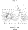
- Fig. 1 is a view illustrating a schematic configuration of a motorcycle 1 according to an embodiment.
- the motorcycle 1 has a vehicle frame 11; a head pipe 12 that is attached to a front end portion of the vehicle frame 11; two front forks 13 that are provided in the head pipe 12; and a front wheel 14 that is attached to lower ends of the two front forks 13.
- the two front forks 13 are respectively disposed on right and left sides of the front wheel 14.
- Fig. 1 illustrates only the front fork 13 that is disposed on the right side. A specific configuration of the front fork 13 will be described later.
- the motorcycle 1 has a handlebar 15 that is attached to upper portions of the front forks 13; a fuel tank 16 that is attached to a front upper portion of the vehicle frame 11; and an engine 17 and a transmission 18 which are disposed below the fuel tank 16.
- the motorcycle 1 has a seat 19 that is attached to a rear upper portion of the vehicle frame 11; a swing arm 20 that is swingably attached to a lower portion of the vehicle frame 11; a rear wheel 21 that is attached to a rear end of the swing arm 20; and one or two rear suspensions 22 that are attached between a rear portion (the rear wheel 21) of the swing arm 20 and a rear portion of the vehicle frame 11.
- the one or the two rear suspensions 22 are respectively disposed on right and left sides of the rear wheel 21.
- Fig. 1 illustrates only the rear suspension 22 that is disposed on the right side. A specific configuration of the rear suspension 22 will be described later.
- the motorcycle 1 has a head lamp 23 that is disposed in front of the head pipe 12; a front fender 24 that is attached to the front forks 13 so as to cover an upper portion of the front wheel 14; a tail lamp 25 that is disposed in the back of the seat 19; and a rear fender 26 that is attached below the tail lamp 25 so as to cover an upper portion of the rear wheel 21.
- the motorcycle 1 has a brake 27 for stopping the rotation of the front wheel 14.
- the motorcycle 1 has a front wheel rotation detection sensor 31 that detects a rotation angle of the front wheel 14, and a rear wheel rotation detection sensor 32 that detects a rotation angle of the rear wheel 21.
- the motorcycle 1 has a load detection sensor 33 that detects a load exerted on the front wheel 14 and the rear wheel 21 from the vehicle frame 11 when an occupant gets on or luggage is mounted on the seat 19 and the like.
- the motorcycle 1 includes a control device 50 as an example of the control unit that controls the degree of opening of a front wheel electromagnetic valve 270 of the front fork 13, which will be describe later and the degree of opening of a rear wheel electromagnetic valve 170 of the rear suspension 22, which will be described later.
- the control device 50 controls a vehicle height of the motorcycle 1 by controlling the degree of opening of the front wheel electromagnetic valve 270 and the rear wheel electromagnetic valve 170 which will be described later.
- the control device 50 receives signals output from the front wheel rotation detection sensor 31, the rear wheel rotation detection sensor 32, the load detection sensor 33, and the like.
- Fig. 2 is a cross-sectional view of the rear suspension 22.
- the rear suspension 22 is attached between the vehicle frame 11 as an example of a vehicle body and the rear wheel 21 of the motorcycle 1.
- the rear suspension 22 includes a rear wheel suspension spring 110 as an example of a spring that supports the weight of the motorcycle 1, and absorbs an impact, and a rear wheel damper 120 as an example of a damper that dampens vibration of the rear wheel suspension spring 110.
- the rear suspension 22 includes a rear wheel relative position changing device 140 that can change a rear wheel relative position indicating a relative position between the vehicle frame 11 and the rear wheel 21 by adjusting the spring force of the rear wheel suspension spring 110, and a rear wheel liquid supply device 160 that supplies liquid to the rear wheel relative position changing device 140.
- the rear suspension 22 includes a vehicle body side attachment member 184 through which the rear suspension 22 is attached to the vehicle frame 11; a vehicle axle-side attachment member 185 through which the rear suspension 22 is attached to the rear wheel 21; and a spring receiver 190 that is attached to the vehicle axle-side attachment member 185 so as to support one end portion (a lower portion in Fig. 2 ) of the rear wheel suspension spring 110 in a centerline direction.
- the rear suspension 22 functions as an example of change means that can change a relative position between the vehicle frame 11 and the rear wheel 21 as an example of a tire wheel, and as an example of rear wheel-side change means.
- the rear wheel damper 120 includes a cylinder 125 having a thin-wall cylindrical outer cylinder 121; a thin-wall cylindrical inner cylinder 122 that is accommodated in the outer cylinder 121; a bottom cover 123 that blocks one end portion (a lower portion in Fig. 2 ) of the cylindrical outer cylinder 121 in a centerline direction (in the vertical direction in Fig. 2 ) of the outer cylinder 121; and an upper cover 124 that blocks one end portion (an upper portion in Fig. 2 ) of the inner cylinder 122 in the centerline direction.
- the centerline direction of the outer cylinder 121 is simply referred to as the "centerline direction”.
- the rear wheel damper 120 includes a piston 126 that is inserted into the inner cylinder 122 so as to be movable in the centerline direction, and a piston rod 127 that extends in the centerline direction, and supports the piston 126 by one end portion (an upper end portion in Fig. 2 ) of the piston rod 127 in the centerline direction.
- the piston 126 is in contact with an inner circumferential surface of the inner cylinder 122, and divides a liquid (oil in the embodiment) sealed space in the cylinder 125 into a first oil chamber 131 and a second oil chamber 132.
- the first oil chamber 131 is positioned on one end side of the piston 126 in the centerline direction, and the second oil chamber 132 is positioned on the other end side of the piston 126 in the centerline direction.
- the piston rod 127 is a cylindrical member, and a pipe 161 to be described later is inserted into the piston rod 127.
- oil functions as an example of working oil.
- the rear wheel damper 120 includes a first damping force generating apparatus 128 that is disposed in one end portion of the piston rod 127 in the centerline direction, and a second damping force generating apparatus 129 that is disposed in the other end portion of the inner cylinder 122 in the centerline direction.
- the first damping force generating apparatus 128 and the second damping force generating apparatus 129 dampen extensional and contractional vibration of the cylinder 125 and the piston rod 127, which is occurring when the rear wheel suspension spring 110 absorbs an impact force from a road surface.
- the first damping force generating apparatus 128 is disposed to function as a connection path between the first oil chamber 131 and the second oil chamber 132.
- the second damping force generating apparatus 129 is disposed to function as a connection path between the second oil chamber 132 and a jack chamber 142 of the rear wheel relative position changing device 140, which will be described later.
- the rear wheel liquid supply device 160 undergoes a pumping operation by an extensional and contractional movement of the piston rod 127 relative to the cylinder 125 so that the rear wheel liquid supply device 160 supplies liquid into the jack chamber 142 of the rear wheel relative position changing device 140, which will be described later.
- the rear wheel liquid supply device 160 has the cylindrical pipe 161 that is fixed to the cover 124 of the rear wheel damper 120 so as to extend in the centerline direction.
- the pipe 161 is coaxially inserted into a pump chamber 162 which is an inner portion of the cylindrical piston rod 127.
- the rear wheel liquid supply device 160 has a discharge check valve 163 and a suction check valve 164.
- a discharge check valve 163 When the piston rod 127 moves to enter the cylinder 125 and the pipe 161, liquid in the pump chamber 162 is pressurized and discharged into the jack chamber 142, which will be described later, via the discharge check valve 163.
- a pressure of the pump chamber 162 becomes negative, and liquid in the cylinder 125 is suctioned into the pump chamber 162 via the suction check valve 164.
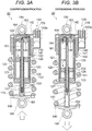
- Figs. 3A and 3B are views describing an operation of the rear wheel liquid supply device 160.
- the rear wheel liquid supply device 160 When the rear suspension 22 receives a force caused by concave and convex road surfaces while the motorcycle 1 is travelling, the rear wheel liquid supply device 160 with the aforementioned configuration undergoes a pumping operation by an extensional and contractional movement in which the piston rod 127 enters and retracts from the cylinder 125 and the pipe 161.
- the discharge check valve 163 When the pump chamber 162 is pressured by the pumping operation, the discharge check valve 163 is opened by liquid in the pump chamber 162, and the liquid is discharged into the jack chamber 142 of the rear wheel relative position changing device 140 (refer to Fig. 3A ).
- the rear wheel relative position changing device 140 has a support member 141 that is disposed to cover an outer circumference of the cylinder 125 of the rear wheel damper 120, and supports the other end portion (an upper portion in Figs. 3A and 3B ) of the rear wheel suspension spring 110 in the centerline direction.
- the rear wheel relative position changing device 140 also has a hydraulic jack 143 that is disposed to cover an outer circumference of one end portion (an upper portion in Figs. 3A and 3B ) of the cylinder 125 in the centerline direction, and forms the jack chamber 142 along with the support member 141.
- the support member 141 moves relative to the hydraulic jack 143 in the centerline direction.
- the vehicle body side attachment member 184 is attached to an upper portion of the hydraulic jack 143, and the support member 141 moves relative to the hydraulic jack 143 in the centerline direction. Accordingly, the spring force of the rear wheel suspension spring 110 changes, thereby changing a position of the seat 19 relative to the rear wheel 21.
- the rear wheel relative position changing device 140 has a rear wheel electromagnetic valve 170 which is an electromagnetic valve (a solenoid valve) provided in a fluid flow path between the jack chamber 142 and a liquid reservoir chamber 143a formed in the hydraulic jack 143.
- a rear wheel electromagnetic valve 170 is an electromagnetic valve (a solenoid valve) provided in a fluid flow path between the jack chamber 142 and a liquid reservoir chamber 143a formed in the hydraulic jack 143.
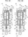
- Figs. 4A and 4B are views describing adjustment of a vehicle height by the rear wheel relative position changing device 140.
- the amount of compression (a change in distance between the vehicle body side attachment member 184 and the vehicle axle-side attachment member 185) of the rear suspension 22 decreases.
- the support member 141 moves relative to the hydraulic jack 143, and thus the spring length of the rear wheel suspension spring 110 becomes shortened, the height of the seat 19 is increased (the vehicle height is increased) further compared to when the support member 141 does not move relative to the hydraulic jack 143. That is, the degree of opening of the rear wheel electromagnetic valve 170 decreases, and thus the vehicle height is increased.
- the height of the seat 19 decreases (the vehicle height decreases) further compared to when the support member 141 does not move relative to the hydraulic jack 143. That is, the vehicle height decreases to the extent that the degree of opening of the rear wheel electromagnetic valve 170 increases.
- the degree of opening of the rear wheel electromagnetic valve 170 is controlled by the control device 50.
- liquid supplied into the jack chamber 142 may be discharged into the first oil chamber 131 and/or the second oil chamber 132 of the cylinder 125.
- a return path 121a is provided in the outer cylinder 121 of the cylinder 125.
- the support member 141 moves to a predetermined limit position toward one end portion (the lower portion in Fig. 2 ) of the hydraulic jack 143 in the centerline direction, liquid in the jack chamber 142 returns into the cylinder 125 via the return path 121a.
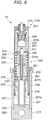
- Fig. 5 is a view illustrating a mechanism in which the vehicle height is maintained.
- the state of the rear suspension 22 is referred to as a minimum state.
- the state of the rear suspension 22 is referred to as a maximum state.
- the rear suspension 22 has a rear wheel relative position detection unit 195 (refer to Fig. 11 ).
- the rear wheel relative position detection unit 195 can detect the amount of movement of the support member 141 relative to the hydraulic jack 143 in the centerline direction, or in other words, the amount of movement of the support member 141 relative to the vehicle body side attachment member 184 in the centerline direction.
- coils are wound around an outer circumferential surface of the support member 141, and the hydraulic jack 143 is formed of a magnetic body.
- the rear wheel relative position detection unit 195 can detect the amount of movement of the support member 141 based on impedance of the coils, which changes according to the movement of the support member 141 relative to the hydraulic jack 143 in the centerline direction.
- Fig. 6 is a cross-sectional view of the front fork 13.
- the front fork 13 is attached between the vehicle frame 11 and the front wheel 14.
- the front fork 13 includes a front wheel suspension spring 210 that supports the weight of the motorcycle 1, and absorbs an impact, and a front wheel damper 220 that dampens vibration of the front wheel suspension spring 210.
- the front fork 13 includes a front wheel relative position changing device 240 that can change a front wheel relative position indicating a relative position between the vehicle frame 11 and the front wheel 14 by adjusting the spring force of the front wheel suspension spring 210, and a front wheel liquid supply device 260 that supplies liquid to the front wheel relative position changing device 240.
- the front fork 13 includes a vehicle axle-side attachment portion 285 and a head pipe-side attachment portion (not illustrated).
- the front fork 13 is attached to the front wheel 14 via the vehicle axle-side attachment portion 285, and the front fork 13 is attached to the head pipe 12 via the head pipe-side attachment portion.
- the front fork 13 functions as an example of the change means that changes a relative position between the vehicle frame 11 and the front wheel 14.
- the front fork 13 functions as an example of the change means that can change a relative position between the vehicle frame 11 and the front wheel 14 as an example of the tire wheel, and as an example of front wheel-side change means.
- the front wheel damper 220 includes a cylinder 225 having a thin-wall cylindrical outer cylinder 221; a thin-wall cylindrical inner cylinder 222, one end portion (a lower portion in Fig. 6 ) of which is inserted into the cylindrical outer cylinder 221 via one end portion (an upper portion in Fig. 6 ) of the outer cylinder 221 in a centerline direction (in the vertical direction in Fig. 6 ) ; a bottom cover 223 that blocks the other end portion (a lower portion in Fig. 6 ) of the outer cylinder 221 in the centerline direction; and an upper cover 224 that blocks the other end portion (an upper portion in Fig. 6 ) of the inner cylinder 222 in the centerline direction.
- the inner cylinder 222 is slidably inserted into the outer cylinder 221.
- the front wheel damper 220 includes a piston rod 227 that is attached to the bottom cover 223 so as to extend in the centerline direction.
- the piston rod 227 has a cylindrical portion 227a that extends in the centerline direction, and a disc-shaped flange portion 227b that is provided in one end portion (an upper portion in Fig. 6 ) of the cylindrical portion 227a in the centerline direction.
- the front wheel damper 220 is fixed to one end portion (the lower portion in Fig. 6 ) of the inner cylinder 222 in the centerline direction, and includes a piston 226 that is slidable relative to an outer circumference of the cylindrical portion 227a of the piston rod 227.
- the piston 226 is in contact with an outer circumferential surface of the cylindrical portion 227a of the piston rod 227, and divides a liquid (oil in the embodiment) sealed space in the cylinder 225 into a first oil chamber 231 and a second oil chamber 232.
- the first oil chamber 231 is positioned on one end side of the piston 226 in the centerline direction
- the second oil chamber 232 is positioned on the other end side of the piston 226 in the centerline direction.
- oil functions as an example of working oil.
- the front wheel damper 220 includes a cover member 230 that is provided above the piston rod 227 so as to cover an aperture of the cylindrical portion 227a of the piston rod 227.
- the cover member 230 supports one end portion (a lower portion in Fig. 6 ) of the front wheel suspension spring 210 in the centerline direction.
- the front wheel damper 220 has an oil reservoir chamber 233 including a space that is formed in the inner cylinder 222 on one end side of the cover member 230 in the centerline direction, and a space that is formed in the cylindrical portion 227a of the piston rod 227.
- the oil reservoir chamber 233 communicates with the first oil chamber 231 and the second oil chamber 232 all the time.
- the front wheel damper 220 includes a first dampening force generation portion 228 that is provided in the piston 226, and a second dampening force generation portion 229 that is formed in the piston rod 227.
- the first dampening force generation portion 228 and the second dampening force generation portion 229 dampen extensional and contractional vibration of the inner cylinder 222 and the piston rod 227, which is occurring when the front wheel suspension spring 210 absorbs an impact force from a road surface.
- the first dampening force generation portion 228 is disposed to function as a connection path between the first oil chamber 231 and the second oil chamber 232.
- the second dampening force generation portion 229 is formed to function as a connection path between the first oil chamber 231, the second oil chamber 232 and the oil reservoir chamber 233.
- the front wheel liquid supply device 260 undergoes a pumping operation by an extensional and contractional movement of the piston rod 227 relative to the inner cylinder 222 so that the front wheel liquid supply device 260 supplies liquid into a jack chamber 242 of the front wheel relative position changing device 240, which will be described later.
- the front wheel liquid supply device 260 has a cylindrical pipe 261 that is fixed to the cover member 230 of the front wheel damper 220 so as to extend in the centerline direction.
- the pipe 261 is coaxially inserted into a pump chamber 262 which is an inner portion of a lower cylindrical portion 241a of a support member 241 of the front wheel relative position changing device 240, which will be described later.
- the front wheel liquid supply device 260 has a discharge check valve 263 and a suction check valve 264.
- a discharge check valve 263 When the piston rod 227 moves to enter the inner cylinder 222, liquid in the pump chamber 262 is pressurized and discharged into the jack chamber 242, which will be described later, via the discharge check valve 263.
- a pressure of the pump chamber 262 becomes negative, and liquid in the oil reservoir chamber 233 is suctioned into the pump chamber 262 via the suction check valve 264.
- Figs. 7A and 7B are views describing an operation of the front wheel liquid supply device 260.
- the front wheel liquid supply device 260 With the aforementioned configuration undergoes a pumping operation.
- the pump chamber 262 is pressured by the pumping operation, the discharge check valve 263 is opened by liquid in the pump chamber 262, and the liquid is discharged into the jack chamber 242 of the front wheel relative position changing device 240 (refer to Fig. 7A ).
- the suction check valve 264 is opened by liquid in the oil reservoir chamber 233, and the liquid is suctioned into the pump chamber 262 (refer to Fig. 7B ).
- the front wheel relative position changing device 240 includes the support member 241 that is disposed in the inner cylinder 222 of the front wheel damper 220, and supports the other end portion (an upper portion in Figs. 7A and 7B ) of the front wheel suspension spring 210 in the centerline direction via a disc-shaped spring receiver 244.
- the support member 241 has the cylindrical lower cylindrical portion 241a formed in one end portion (a lower portion in Figs. 7A and 7B ) of the support member 241 in the centerline direction, and a cylindrical upper cylindrical portion 241b formed in the other end portion (an upper portion in Figs. 7A and 7B ) of the support member 241 in the centerline direction.
- the pipe 261 is inserted into the lower cylindrical portion 241a.
- the front wheel relative position changing device 240 has a hydraulic jack 243 that is fitted into the upper cylindrical portion 241b of the support member 241, and forms the jack chamber 242 along with the support member 241.
- the support member 241 moves relative to the hydraulic jack 243 in the centerline direction.
- the head pipe-side attachment portion (not illustrated) is attached to an upper portion of the hydraulic jack 243, and the support member 241 moves relative to the hydraulic jack 243 in the centerline direction. Accordingly, the spring force of the front wheel suspension spring 210 changes, thereby changing a position of the seat 19 relative to the front wheel 14.
- the front wheel relative position changing device 240 has a front wheel electromagnetic valve 270 which is an electromagnetic valve (a solenoid valve) provided in a fluid flow path between the jack chamber 242 and the oil reservoir chamber 233.
- a front wheel electromagnetic valve 270 is an electromagnetic valve (a solenoid valve) provided in a fluid flow path between the jack chamber 242 and the oil reservoir chamber 233.
- the front wheel electromagnetic valve 270 is closed, liquid supplied into the jack chamber 242 is reserved in the jack chamber 242.
- the front wheel electromagnetic valve 270 is open, the liquid supplied into the jack chamber 242 is discharged into the oil reservoir chamber 233.
- the front wheel electromagnetic valve 270 will be described in detail later.
- Figs. 8A and 8B are views describing adjustment of the vehicle height by the front wheel relative position changing device 240.
- the jack chamber 242 When the front wheel liquid supply device 260 supplies liquid into the jack chamber 242 in a state in which the front wheel electromagnetic valve 270 is even a little closed from a fully open state, the jack chamber 242 is filled with the liquid, the support member 241 moves toward one end portion (a lower portion in Fig. 8A ) of the hydraulic jack 243 in the centerline direction, and the spring length of the front wheel suspension spring 210 becomes shortened (refer to Fig. 8A ). In contrast, when the front wheel electromagnetic valve 270 is fully open, the liquid in the jack chamber 242 is discharged into the oil reservoir chamber 233, the support member 241 moves toward the other end portion (an upper portion in Fig. 8B ) of the hydraulic jack 243 in the centerline direction, and the spring length of the front wheel suspension spring 210 becomes lengthened (refer to Fig. 8B ).
- the amount of compression (a change in distance between the head pipe-side attachment member (not illustrated) and the vehicle axle-side attachment portion 285) of the front fork 13 decreases.
- the support member 241 moves relative to the hydraulic jack 243, and thus the spring length of the front wheel suspension spring 210 becomes shortened, the height of the seat 19 is increased (the vehicle height is increased) further compared to when the support member 241 does not move relative to the hydraulic jack 243. That is, the degree of opening of the front wheel electromagnetic valve 270 decreases, and thus the vehicle height is increased.
- the height of the seat 19 decreases (the vehicle height decreases) further compared to when the support member 241 does not move relative to the hydraulic jack 243. That is, the vehicle height decreases to the extent that the degree of opening of the front wheel electromagnetic valve 270 increases.
- the degree of opening of the front wheel electromagnetic valve 270 is controlled by the control device 50.
- liquid supplied into the jack chamber 242 may be discharged into the first oil chamber 231 and/or the second oil chamber 232.
- Fig. 9 is a view illustrating a mechanism in which the vehicle height is maintained.
- a return path (not illustrated) is provided in an outer circumferential surface of the hydraulic jack 243.
- the support member 241 moves to a predetermined limit position toward one end portion (the lower portions in Fig. 8A and 8B ) of the hydraulic jack 243 in the centerline direction, liquid in the jack chamber 242 returns into the oil reservoir chamber 233 via the return path.
- the front wheel electromagnetic valve 270 When the front wheel electromagnetic valve 270 is closed, and liquid is continuously supplied into the jack chamber 242, the supplied liquid returns into the oil reservoir chamber 233 via the return path. Accordingly, the position of the support member 241 is maintained relative to the hydraulic jack 243, or the height of the seat 19 (the vehicle height) is maintained.
- the state of the front fork 13 is referred to as a minimum state.
- the state of the front fork 13 is referred to as a maximum state.
- the front fork 13 has a front wheel relative position detection unit 295 (refer to Fig. 11 ).
- the front wheel relative position detection unit 295 can detect the amount of movement of the support member 241 relative to the hydraulic jack 243 in the centerline direction, or in other words, the amount of movement of the support member 241 relative to the head pipe-side attachment member in the centerline direction.
- coils are wound around an outer circumferential surface in a radial direction of the inner cylinder 222 at a position which corresponds to the support member 241 in the centerline direction, and the support member 241 is formed of a magnetic body.
- the front wheel relative position detection unit 295 can detect the amount of movement of the support member 241 based on impedance of the coils, which changes according to the movement of the support member 241 relative to the hydraulic jack 243 in the centerline direction.
- Fig. 10A is a view illustrating the schematic configuration of the front wheel electromagnetic valve 270
- Fig. 10B is a view illustrating the schematic configuration of a rear wheel electromagnetic valve 170.
- the front wheel electromagnetic valve 270 is a so-called normally open electromagnetic valve. As illustrated in Fig. 10A , the front wheel electromagnetic valve 270 includes a bobbin 272 around which a coil 271 is wound; a bar-shaped stator core 273 that is fixed to a hollow portion 272a of the bobbin 272; a holder 274 that supports the coil 271, the bobbin 272, and the stator core 273; and a substantially disc-shaped moving core 275 that is disposed to correspond to a tip (an end surface) of the stator core 273, and is drawn toward the stator core 273.
- the front wheel electromagnetic valve 270 includes a valve body 276 which is fixed to the center of the tip of the moving core 275; a body 277 which is assembled with the holder 274; a valve chamber 278 which is formed in the body 277, and in which the valve body 276 is disposed; a cover member 279 which covers an aperture portion formed in the body 277, and forms the valve chamber 278 along with the body 277; and a coil spring 280 which is disposed between the valve body 276 and the cover member 279.
- the front wheel electromagnetic valve 270 includes a valve seat 281 which is formed in the body 277, and is disposed in the valve chamber 278 so as to correspond to the valve body 276; an introduction flow path 282 which is formed in the body 277, and through which liquid is introduced into the valve chamber 278 from the jack chamber 242 (refer to Fig. 9 ); and an output flow path 283 which is formed in the body 277, and through which liquid is output into the oil reservoir chamber 233 from the valve chamber 278 via the valve seat 281.
- the front wheel electromagnetic valve 270 may be a normally closed electromagnetic valve.
- the rear wheel electromagnetic valve 170 is a so-called normally open electromagnetic valve. As illustrated in Fig. 10B , the rear wheel electromagnetic valve 170 includes a bobbin 172 around which a coil 171 is wound; a bar-shaped stator core 173 that is fixed to a hollow portion 172a of the bobbin 172; a holder 174 that supports the coil 171, the bobbin 172, and the stator core 173; and a substantially disc-shaped moving core 175 that is disposed to correspond to a tip (an end surface) of the stator core 173, and is drawn toward the stator core 173.
- the rear wheel electromagnetic valve 170 includes a valve body 176 which is fixed to the center of the tip of the moving core 175; a body 177 which is assembled with the holder 174; a valve chamber 178 which is formed in the body 177, and in which the valve body 176 is disposed; a cover member 179 which covers an aperture portion formed in the body 177, and forms the valve chamber 178 along with the body 177; and a coil spring 180 which is disposed between the valve body 176 and the cover member 179.
- the rear wheel electromagnetic valve 170 includes a valve seat 181 which is formed in the body 177, and is disposed in the valve chamber 178 so as to correspond to the valve body 176; an introduction flow path 182 which is formed in the body 177, and through which liquid is introduced into the valve chamber 178 from the jack chamber 142 (refer to Fig. 5 ); and an output flow path 183 which is formed in the body 177, and through which liquid is output into the liquid reservoir chamber 143a from the valve chamber 178 via the valve seat 181.
- the rear wheel electromagnetic valve 170 may be a normally closed electromagnetic valve.
- the moving cores 275 and 175 are respectively biased toward the bottom in Figs. 10A and 10B by the coil springs 280 and 180, and thus the valve bodies 276 and 176 are not in contact with the valve seats 281 and 181, respectively.
- the valve bodies 276 and 176 are respectively fixed to the tips (the end surfaces) of the moving cores 275 and 175. For this reason, the introduction flow paths 282 and 182 communicate with the output flow paths 283 and 183, respectively, and the front wheel electromagnetic valve 270 and the rear wheel electromagnetic valve 170 are open.
- the moving cores 275 and 175 are respectively displaced based on balance between an induction force of the stator core 273 and a bias force of the coil spring 280, and balance between an induction force of the stator core 173 and a bias force of the coil spring 180.
- the front wheel electromagnetic valve 270 and the rear wheel electromagnetic valve 170 adjust positions of the valve bodies 276 and 176 relative to the valve seats 281 and 181, respectively. That is, the front wheel electromagnetic valve 270 and the rear wheel electromagnetic valve 170 adjust the degree of opening of the valves, respectively. The degree of opening of the valves is respectively adjusted by changes in electric power (current and voltage) supplied to the coils 271 and 171.
- control device 50 will be described.
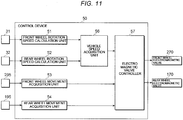
- Fig. 11 is a block diagram of a control device 50.
- the control device 50 includes a CPU; a ROM that stores a program which is executed by the CPU, various data and the like; a RAM that is used as a CPU's working memory and the like, and an EEPROM which is a non-volatile memory.
- the control device 50 receives signals output from the front wheel rotation detection sensor 31; the rear wheel rotation detection sensor 32; the front wheel relative position detection unit 295; the rear wheel relative position detection unit 195; and the like.
- the control device 50 includes a front wheel rotation speed calculation unit 51 and a rear wheel rotation speed calculation unit 52.
- the front wheel rotation speed calculation unit 51 calculates a rotation speed of the front wheel 14 based on a signal output from the front wheel rotation detection sensor 31.
- the rear wheel rotation speed calculation unit 52 that calculates a rotation speed of the rear wheel 21 based on a signal output from the rear wheel rotation detection sensor 32.
- the front wheel rotation speed calculation unit 51 and the rear wheel rotation speed calculation unit 52 acquire rotation angles of the front wheel 14 and the rear wheel 21 respectively based on pulse signals which are the signals output from the sensors, and then calculate rotation speeds by differentiating the acquired rotation angles over elapsed times.
- the control device 50 includes a front wheel movement acquisition unit 53 that acquires a front wheel movement Lf based on a signal output from the front wheel relative position detection unit 295.
- the front wheel movement Lf is the amount of movement of the support member 241 of the front wheel relative position changing device 240 (refer to Figs. 8A and 8B ) relative to the hydraulic jack 243.
- the control device 50 includes a rear wheel movement acquisition unit 54 that acquires a rear wheel movement Lr based on a signal output from the rear wheel relative position detection unit 195.
- the rear wheel movement Lr is the amount of movement of the support member 141 of the rear wheel relative position changing device 140 relative to the hydraulic jack 143.
- the front wheel movement acquisition unit 53 and the rear wheel movement acquisition unit 54 can acquire the front wheel movement Lf and the rear wheel movement Lr respectively based on respective correlations between the impedance of the coil that is stored in the ROM in advance, and the front wheel movement Lf, and between the impedance of the coil that is stored in the ROM in advance, and the rear wheel movement Lr.
- the control device 50 includes a vehicle speed acquisition unit 56 that acquires a vehicle speed Vc, which is a moving speed of the motorcycle 1, based on the rotation speed of the front wheel 14 calculated by the front wheel rotation speed calculation unit 51 and/or the rotation speed of the rear wheel 21 calculated by the rear wheel rotation speed calculation unit 52.
- the vehicle speed acquisition unit 56 acquires the vehicle speed Vc by calculating a moving speed of the front wheel 14 or a moving speed of the rear wheel 21 based on a front wheel rotation speed Rf or a rear wheel rotation speed Rr.
- the moving speed of the front wheel 14 can be calculated based on the front wheel rotation speed Rf and the outer diameter of a tire of the front wheel 14.
- the moving speed of the rear wheel 21 can be calculated based on the rear wheel rotation speed Rr and the outer diameter of a tire of the rear wheel 21.
- the vehicle speed Vc is equal to the moving speed of the front wheel 14 or the moving speed of the rear wheel 21.
- the vehicle speed acquisition unit 56 may acquire the vehicle speed Vc by calculating an average moving speed of the front wheel 14 and the rear wheel 21 based on an average value of the front wheel rotation speed Rf and the rear wheel rotation speed Rr.
- the control device 50 has an electromagnetic valve controller 57 that controls the degree of opening of the front wheel electromagnetic valve 270 of the front wheel relative position changing device 240 and the degree of opening of the rear wheel electromagnetic valve 170 of the rear wheel relative position changing device 140 based on the vehicle speed Vc acquired by the vehicle speed acquisition unit 56.
- the electromagnetic valve controller 57 will be described in detail later.
- the CPU executes software stored in a storage area such as the ROM so as to realize the front wheel rotation speed calculation unit 51, the rear wheel rotation speed calculation unit 52, the front wheel movement acquisition unit 53, the rear wheel movement acquisition unit 54, the vehicle speed acquisition unit 56, and the electromagnetic valve controller 57.
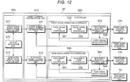
- Fig. 12 is a block diagram of the electromagnetic valve controller 57 according to the embodiment.
- the electromagnetic valve controller 57 has a target movement determination unit 570.
- the target movement determination unit 570 has a front wheel target movement determination unit 571 that determines a front wheel target movement which is a target movement of the front wheel movement Lf; and a rear wheel target movement determination unit 572 that determines a rear wheel target movement which is a target movement of the rear wheel movement Lr; and a weight acquisition unit 575 that acquires the weight exerted on the motorcycle 1 as an example of the vehicle.
- the electromagnetic valve controller 57 has a target current determination unit 510 and a controller 520.
- the target current determination unit 510 determines a target current supplied to the front wheel electromagnetic valve 270 of the front wheel relative position changing device 240, and a target current supplied to the rear wheel electromagnetic valve 170 of the rear wheel relative position changing device 140.
- the controller 520 performs a feedback control based on the target currents determined by the target current determination unit 510.
- the target movement determination unit 570 determines a target movement based on the vehicle speed Vc acquired by the vehicle speed acquisition unit 56 (refer to Fig. 11 ) and the weight exerted on the motorcycle 1 which is acquired by the weight acquisition unit 575.
- the weight acquisition unit 575 acquires the weight exerted on the motorcycle 1 based on the weight input via the input device 34 that is provided on the motorcycle 1.
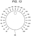
- Fig. 13 is an exterior appearance view of the input device 34.
- the input device 34 is a so-called dial-type device having weight numerals written thereon.
- a user can select the weight exerted on the motorcycle 1 by rotating a knob of the input device 34.
- a driver estimates the weight exerted on the motorcycle 1 in consideration of the weight of an occupant on the motorcycle 1 or luggage to be carried by the motorcycle 1, and the driver selects the weight via the input device 34.
- the weight acquisition unit 575 acquires the weight selected via the input device 34 as the weight exerted on the motorcycle 1.
- the input device 34 may be provided in the vicinity of a speedometer.
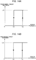
- Fig. 14A is a graph illustrating a correlation between the vehicle speed Vc and the front wheel target movement
- Fig. 14B is a graph illustrating a correlation between the vehicle speed Vc and the rear wheel target movement.
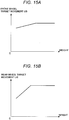
- Fig. 15A is a graph illustrating a relationship between the weight exerted on the motorcycle 1 and the front wheel target movement Lf0
- Fig. 15B is a graph illustrating a relationship between the weight exerted on the motorcycle 1 and the rear wheel target movement Lr0.
- the target movement determination unit 570 sets the target movement to zero.
- the target movement determination unit 570 sets the target movement to a value that is determined in advance based on the weight exerted on the motorcycle 1, which is acquired by the weight acquisition unit 575. More specifically, as illustrated in Fig.
- the front wheel target movement determination unit 571 sets the front wheel target movement to a predetermined front wheel target movement Lf0 that is determined in advance based on the weight exerted on the motorcycle 1 as illustrated in Fig. 15A .
- the front wheel target movement determination unit 571 sets the front wheel target movement to a predetermined front wheel target movement Lf0 that is determined in advance based on the weight exerted on the motorcycle 1 as illustrated in Fig. 15A .
- Fig. 15A In contrast, as illustrated in Fig.
- the rear wheel target movement determination unit 572 sets the rear wheel target movement to a predetermined rear wheel target movement Lr0 that is determined in advance based on the weight exerted on the motorcycle 1 as illustrated in Fig. 15B . Thereafter, while the vehicle speed Vc acquired by the vehicle speed acquisition unit 56 is higher than or equal to the increasing vehicle speed Vu, the front wheel target movement determination unit 571 and the rear wheel target movement determination unit 572 set the front wheel target movement and the rear wheel target movement to the predetermined front wheel target movement Lf0 and the predetermined rear wheel target movement Lr0, respectively.
- the ROM stores in advance a relationship between a selected position of the input device 34 and the weight exerted on the motorcycle 1, a relationship between the weight exerted on the motorcycle 1 and the front wheel target movement Lf0 as illustrated in Fig. 15A , and a relationship between the weight exerted on the motorcycle 1 and the rear wheel target movement Lr0 as illustrated in Fig. 15B .
- the front wheel target movement Lf0 and the rear wheel target movement Lr0 can be determined in advance based on the weight (a selected position of the input device 34) exerted on the motorcycle 1 in such a manner that the vehicle height becomes equal to a predetermined desired vehicle height, and the predetermined front wheel target movement Lf0 and the pretermined rear wheel target movement Lr0 can be stored in the ROM.
- the target movement determination unit 570 sets the target movement to zero. That is, the front wheel target movement determination unit 571 and the rear wheel target movement determination unit 572 set the front wheel target movement and the rear wheel target movement to zero, respectively. It is possible to illustrate 10 km/h and 8 km/h for the increasing vehicle speed Vu and the decreasing vehicle speed Vd, respectively.
- the target movement determination unit 570 sets the target movement to zero. That is, the front wheel target movement determination unit 571 and the rear wheel target movement determination unit 572 set the front wheel target movement and the rear wheel target movement to zero, respectively.
- the fact that the motorcycle 1 undergoes a rapid deceleration can be acquired based on whether the amount of reduction of the vehicle speed Vc acquired by the vehicle speed acquisition unit 56 per unit time is less than or equal to a predetermined value.
- the target current determination unit 510 has a front wheel target current determination unit 511 and a rear wheel target current determination unit 512.
- the front wheel target current determination unit 511 determines a front wheel target current based on the front wheel target movement determined by the front wheel target movement determination unit 571.
- the front wheel target current is a target current of the front wheel electromagnetic valve 270.
- the rear wheel target current determination unit 512 determines a rear wheel target current based on the rear wheel target movement determined by the rear wheel target movement determination unit 572.
- the rear wheel target current is a target current of the rear wheel electromagnetic valve 170.
- the front wheel target current determination unit 511 determines the front wheel target current by substituting the front wheel target movement, which is determined by the front wheel target movement determination unit 571, into a corresponding map between the front wheel target movement and the front wheel target current, and which is prepared based on an empirical rule and is stored in the ROM in advance.
- the rear wheel target current determination unit 512 determines the rear wheel target current by substituting the rear wheel target movement, which is determined by the rear wheel target movement determination unit 572, into a corresponding map between the rear wheel target movement and the rear wheel target current, and which is prepared based on an empirical rule and is stored in the ROM in advance.
- the front wheel target current determination unit 511 and the rear wheel target current determination unit 512 set the front wheel target current and the rear wheel target current to zero, respectively.
- the front wheel target current determination unit 511 and the rear wheel target current determination unit 512 set the front wheel target current and the rear wheel target current, respectively, based on the front wheel target movement and the rear wheel target movement which are respectively determined by the front wheel target movement determination unit 571 and the rear wheel target movement determination unit 572.
- front wheel electromagnetic valve 270 When the front wheel electromagnetic valve 270 is a normally closed electromagnetic valve, and the front wheel target movement is equal to zero, it is necessary to energize the front wheel electromagnetic valve 270.
- rear wheel electromagnetic valve 170 When the rear wheel electromagnetic valve 170 is a normally closed electromagnetic valve, and the rear wheel target movement is equal to zero, it is necessary to energize the rear wheel electromagnetic valve 170.
- the front wheel target current determination unit 511 may perform a feedback control based on a deviation between the front wheel target movement determined by the front wheel target movement determination unit 571 and the actual front wheel movement Lf acquired by the front wheel movement acquisition unit 53 (refer to Fig. 11 ), and the front wheel target current determination unit 511 may determine the front wheel target current.
- the rear wheel target current determination unit 512 may perform a feedback control based on a deviation between the rear wheel target movement determined by the rear wheel target movement determination unit 572 and the actual rear wheel movement Lr acquired by the rear wheel movement acquisition unit 54 (refer to Fig. 11 ), and the rear wheel target current determination unit 512 may determine the rear wheel target current.
- the controller 520 has a front wheel operation controller 530 that controls an operation of the front wheel electromagnetic valve 270; a front wheel electromagnetic valve drive unit 533 that drives the front wheel electromagnetic valve 270; and a front wheel detection unit 534 that detects an actual current flowing through the front wheel electromagnetic valve 270.
- the controller 520 has a rear wheel operation controller 540 that controls an operation of the rear wheel electromagnetic valve 170; a rear wheel electromagnetic valve drive unit 543 that drives the rear wheel electromagnetic valve 170; and a rear wheel detection unit 544 that detects an actual current flowing through the rear wheel electromagnetic valve 170.
- the front wheel operation controller 530 has a front wheel feedback (F/B) controller 531 and a front wheel PWM controller 532.
- the front wheel feedback controller 531 performs a feedback control based on a deviation between the front wheel target current determined by the front wheel target current determination unit 511 and an actual current (an actual front wheel current) detected by the front wheel detection unit 534.
- the front wheel PWM controller 532 performs PWM control of the front wheel electromagnetic valve 270.
- the rear wheel operation controller 540 has a rear wheel feedback (F/B) controller 541 and a rear wheel PWM controller 542.
- the rear wheel feedback controller 541 performs a feedback control based on a deviation between the rear wheel target current determined by the rear wheel target current determination unit 512 and an actual current (an actual rear wheel current) detected by the rear wheel detection unit 544.
- the rear wheel PWM controller 542 performs PWM control of the rear wheel electromagnetic valve 170.
- the front wheel feedback controller 531 obtains a deviation between the front wheel target current and an actual front wheel current detected by the front wheel detection unit 534, and performs a feedback control in such a manner that the deviation becomes zero.
- the rear wheel feedback controller 541 obtains a deviation between the rear wheel target current and an actual rear wheel current detected by the rear wheel detection unit 544, and performs a feedback control in such a manner that the deviation becomes zero.
- the front wheel feedback controller 531 can perform a proportional process and an integral process on the deviation between the front wheel target current and the actual front wheel current by using a proportional element and an integral element, respectively.
- the rear wheel feedback controller 541 can perform a proportional process and an integral process on the deviation between the rear wheel target current and the actual rear wheel current by using a proportional element and an integral element, respectively.
- the processed values can be added by an addition calculation unit.
- the front wheel feedback controller 531 can perform a proportional process, an integral process and a differential process on the deviation between the front wheel target current and the actual front wheel current by using a proportional element, an integral element and a differential element, respectively.
- the rear wheel feedback controller 541 can perform a proportional process, an integral process and a differential process on the deviation between the rear wheel target current and the actual rear wheel current by using a proportional element, an integral element and a differential element, respectively.
- the processed values can be added by the addition calculation unit.
- a pulse-shaped voltage is applied to the coil of the front wheel electromagnetic valve 270 based on the duty ratio.
- a current flowing through the coil 271 of the front wheel electromagnetic valve 270 cannot trace the applied pulse-shaped voltage due to the impedance of the coil 271, and an output of the current is dull.
- the current flowing through the coil of the front wheel electromagnetic valve 270 increases and decreases proportionally to the duty ratio.
- the front wheel PWM controller 532 can set the duty ratio to zero, and when the front wheel target current is equal to the maximum current or a first target current A1 which will be described later, the front wheel PWM controller 532 can set the duty ratio to 100%.
- the rear wheel PWM controller 542 changes a duty ratio, and performs PWM control of the degree of opening (a voltage applied to the coil of the rear wheel electromagnetic valve 170) of the rear wheel electromagnetic valve 170.
- PWM control a pulse-shaped voltage is applied to the coil 171 of the rear wheel electromagnetic valve 170 based on the duty ratio, and a current flowing through the coil 171 of the rear wheel electromagnetic valve 170 increases and decreases proportionally to the duty ratio.
- the rear wheel PWM controller 542 can set the duty ratio to zero, and when the rear wheel target current is equal to the maximum current or a second target current A2 which will be described later, the rear wheel PWM controller 542 can set the duty ratio to 100%.
- the front wheel electromagnetic valve drive unit 533 includes a transistor (FET) as a switching element that is connected between a positive line of a power supply and the coil of the front wheel electromagnetic valve 270.
- the front wheel electromagnetic valve drive unit 533 controls the driving of the front wheel electromagnetic valve 270 by driving a gate of the transistor and causing the transistor to undergo a switching operation.
- the rear wheel electromagnetic valve drive unit 543 includes a transistor that is connected between a positive line of the power supply and the coil of the rear wheel electromagnetic valve 170.
- the rear wheel electromagnetic valve drive unit 543 controls the driving of the rear wheel electromagnetic valve 170 by driving a gate of the transistor and causing the transistor to undergo a switching operation.
- the front wheel detection unit 534 detects an actual current flowing through the front wheel electromagnetic valve 270 from a voltage occurring between opposite ends of a shunt resistance that is connected to the front wheel electromagnetic valve drive unit 533.
- the rear wheel detection unit 544 detects an actual current flowing through the rear wheel electromagnetic valve 170 from a voltage occurring between opposite ends of a shunt resistance that is connected to the rear wheel electromagnetic valve drive unit 543.
- the electromagnetic valve controller 57 of the control device 50 determines the target current based on the target movement associated with the weight exerted on the motorcycle 1, and performs PWM control in such a manner that actual currents supplied to the front wheel electromagnetic valve 270 and the rear wheel electromagnetic valve 170 become equal to the determined target currents. That is, the front wheel PWM controller 532 and the rear wheel PWM controller 542 of the electromagnetic valve controller 57 change the duty ratios, and thus control electric power supplied to the coil 271 of the front wheel electromagnetic valve 270 and the coil 171 of the rear wheel electromagnetic valve 170, respectively, and control the front wheel electromagnetic valve 270 and the rear wheel electromagnetic valve 170 to open to an arbitrary degree of opening, respectively.
- the control device 50 controls upper limits of the amount of liquid (oil) flowing into the jack chamber 242 and the jack chamber 142 by controlling the degree of opening of the front wheel electromagnetic valve 270 and the rear wheel electromagnetic valve 170, the control device 50 can change the target movements to the target movements which are determined based on the weight exerted on the motorcycle 1 as illustrated in Figs. 15A and 15B .
- the weight exerted on the motorcycle 1 As the weight becomes larger, the front wheel target movement Lf0 and the rear wheel target movement Lr0 become larger.
- the front wheel PWM controller 532 and the rear wheel PWM controller 542 of the electromagnetic valve controller 57 may control the front wheel electromagnetic valve 270 and the rear wheel electromagnetic valve 170, respectively, in such a manner that the detected movements coincide with the target movements.
- the front wheel PWM controller 532 and the rear wheel PWM controller 542 determine the target currents based on the target movements and the detected movements, respectively.
- the target movement determination unit 570 sets the target movement to zero.
- the minimum target movement may not be set to zero, and instead, the minimum target movement may be determined based on the weight exerted on the motorcycle 1.
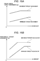
- Fig. 16A is a graph illustrating a relationship between the weight exerted on the motorcycle 1 and the front wheel target movement Lf0
- Fig. 16B is a graph illustrating a relationship between the weight exerted on the motorcycle 1 and the rear wheel target movement Lr0.
- Fig. 16A illustrates the maximum target movement and the minimum target movement of the front wheel target movement Lf0
- Fig. 16B illustrates the maximum target movement and the minimum target movement of the rear wheel target movement Lr0
- the maximum target movement of the front wheel target movement Lf0 illustrated in Fig. 16A is a movement equivalent to the front wheel target movement Lf0 illustrated in Fig. 15A
- the maximum target movement of the rear wheel target movement Lr0 illustrated in Fig. 16B is a movement equivalent to the rear wheel target movement Lr0 illustrated in Fig. 15B .
- the target movement determination unit 570 sets the target movements to the minimum target movements based on the weight exerted on the motorcycle 1 as illustrated in Figs. 16A and 16B .
- control device 50 when the control device 50 controls lower limits of the amount of liquid (oil) flowing into the jack chamber 242 and the jack chamber 142 by controlling the degree of opening of the front wheel electromagnetic valve 270 and the rear wheel electromagnetic valve 170, the control device 50 can change the minimum target movements to the target movements which are determined based on the weight exerted on the motorcycle 1 as illustrated in Figs. 16A and 16B . Accordingly, while the vehicle is travelling at a low speed, the control device 50 can adjust the vehicle height to a desired height regardless of the weight exerted on the motorcycle 1.
- the input device 34 may be a lever-type device in which the user linearly moves a knob, a switch-type device in which the user presses a button for the weight, or a touch panel-type device in which the user presses a display on a screen so as to input the weight.
- the weight acquisition unit 575 acquires the weight exerted on the motorcycle 1 based on the weight input via the input device 34 that is provided on the motorcycle 1.
- the present invention is not limited to the embodiment.
- a weight sensor may be provided in the seat 19 of the motorcycle 1, and the weight acquisition unit 575 may acquire the weight exerted on the motorcycle 1 based on the weight detected by the weight sensor.
- the weight acquisition unit 575 can acquire the weight exerted on the motorcycle 1 based on the value detected by the weight sensor.
- the weight acquisition unit 575 may acquire the weight exerted on the motorcycle 1 dependent on a changing speed of the amount of movement determined based on the front wheel movement Lf and the rear wheel movement Lr when a predetermined period of time elapses after the vehicle height begins to be increased from a state of not being increased.
- the EEPROM or the like may store the weight exerted on the motorcycle 1, which is acquired at a startup, and the weight acquisition unit 575 may read the stored weight at the next startup.
- Each correlation between the weight exerted on the motorcycle 1 and the target movement which is stored in the ROM as illustrated in Figs. 15A, 15B , 16A, and 16B , may undergo an offset correction for the motorcycle 1 after the front fork 13 and the rear suspension 22 are attached to the motorcycle 1. Accordingly, it is possible to correct a variation of each of the front fork 13 and the rear suspension 22.
Landscapes
- Engineering & Computer Science (AREA)
- Mechanical Engineering (AREA)
- General Engineering & Computer Science (AREA)
- Vehicle Body Suspensions (AREA)
- Axle Suspensions And Sidecars For Cycles (AREA)
- Fluid-Damping Devices (AREA)
Description
- The present invention relates to a vehicle height adjustment apparatus that adjusts a vehicle height of a motorcycle.
- In recent years, an apparatus is proposed which increases the vehicle height of a motorcycle while the motorcycle is travelling, and decreases the vehicle height in order for an occupant to easily get on and off the motorcycle at a stop.
- For example, a vehicle height adjustment apparatus disclosed in
JP-B-H08-22680 - In an apparatus that adjusts a vehicle height by changing an initial length of a spring and thus an initial load, the vehicle height is changed by a weight exerted on a vehicle such as the weight of an occupant or the weight of luggage. For example, when the weight exerted on the vehicle is greater than an assumed weight, the vehicle height becomes lower than a desired height. When the weight exerted on the vehicle is less than the assumed weight, the vehicle height becomes higher than the desired height. In particular, since the vehicle height affects ride comfort or travelling stability while the vehicle is travelling, obtaining the desired height regardless of the weight exerted on the vehicle is desired.
- An object of the present invention is to provide a vehicle height adjustment apparatus that can adjust a vehicle height to a desired height regardless of a weight exerted on a vehicle.
- A vehicle height adjustment apparatus according to an aspect of the present invention includes a spring that is disposed between a vehicle body and a tire wheel of a vehicle; a damper that undergoes an extensional and contractional operation so as to move working oil to dampen vibration of the spring; a support member that supports one end portion of the spring, and moves relative to the damper to change the length of the spring; a working oil chamber into which the working oil causing the support member to move relative to the damper flows by the extensional and contractional operation of the damper; an electromagnetic valve that adjusts the amount of the working oil flowing into the working oil chamber by the degree of opening of the electromagnetic valve; and a control unit that controls the degree of opening of the electromagnetic valve based on a weight exerted on the vehicle.
- Here, the control unit may change upper and lower limits of the amount of working oil flowing into the working oil chamber based on the weight exerted on the vehicle.
- According to the present invention, it is possible to provide the vehicle height adjustment apparatus that can adjust the vehicle height to a desired height regardless of the weight exerted on the vehicle.
-
-
Fig. 1 is a view illustrating a schematic configuration of a motorcycle according to an embodiment. -
Fig. 2 is a cross-sectional view of a rear suspension. -
Figs. 3A and 3B are views describing an operation of a rear wheel liquid supply device. -
Figs. 4A and 4B are views describing adjustment of a vehicle height by a rear wheel relative position changing device. -
Fig. 5 is a view illustrating a mechanism in which the vehicle height is maintained. -
Fig. 6 is a cross-sectional view of a front fork. -
Figs. 7A and 7B are views describing an operation of a front wheel liquid supply device. -
Figs. 8A and 8B are views describing adjustment of the vehicle height by a front wheel relative position changing device. -
Fig. 9 is a view illustrating a mechanism in which the vehicle height is maintained. -
Fig. 10A is a view illustrating a schematic configuration of a front wheel electromagnetic valve, andFig. 10B is a view illustrating a schematic configuration of a rear wheel electromagnetic valve. -
Fig. 11 is a block diagram of a control device. -
Fig. 12 is a block diagram of an electromagnetic valve controller according to the embodiment. -
Fig. 13 is an exterior appearance view of an input device. -
Fig. 14A is a graph illustrating a correlation between a vehicle speed and a front wheel target movement, andFig. 14B is a graph illustrating a correlation between the vehicle speed and a rear wheel target movement. -
Fig. 15A is a graph illustrating a relationship between a weight exerted on the motorcycle and the front wheel target movement, andFig. 15B is a graph illustrating a relationship between the weight exerted on the motorcycle and the rear wheel target movement. -
Fig. 16A is a graph illustrating a relationship between the weight exerted on the motorcycle and the front wheel target movement, andFig. 16B is a graph illustrating a relationship between the weight exerted on the motorcycle and the rear wheel target movement. - Hereinafter, embodiments of the present invention will be described with reference to the accompanying drawings.
-
Fig. 1 is a view illustrating a schematic configuration of amotorcycle 1 according to an embodiment. - As illustrated in
Fig. 1 , themotorcycle 1 has avehicle frame 11; ahead pipe 12 that is attached to a front end portion of thevehicle frame 11; twofront forks 13 that are provided in thehead pipe 12; and afront wheel 14 that is attached to lower ends of the twofront forks 13. The twofront forks 13 are respectively disposed on right and left sides of thefront wheel 14.Fig. 1 illustrates only thefront fork 13 that is disposed on the right side. A specific configuration of thefront fork 13 will be described later. - The
motorcycle 1 has ahandlebar 15 that is attached to upper portions of thefront forks 13; afuel tank 16 that is attached to a front upper portion of thevehicle frame 11; and anengine 17 and atransmission 18 which are disposed below thefuel tank 16. - The
motorcycle 1 has aseat 19 that is attached to a rear upper portion of thevehicle frame 11; aswing arm 20 that is swingably attached to a lower portion of thevehicle frame 11; arear wheel 21 that is attached to a rear end of theswing arm 20; and one or tworear suspensions 22 that are attached between a rear portion (the rear wheel 21) of theswing arm 20 and a rear portion of thevehicle frame 11. The one or the tworear suspensions 22 are respectively disposed on right and left sides of therear wheel 21.Fig. 1 illustrates only therear suspension 22 that is disposed on the right side. A specific configuration of therear suspension 22 will be described later. - The
motorcycle 1 has ahead lamp 23 that is disposed in front of thehead pipe 12; afront fender 24 that is attached to thefront forks 13 so as to cover an upper portion of thefront wheel 14; atail lamp 25 that is disposed in the back of theseat 19; and arear fender 26 that is attached below thetail lamp 25 so as to cover an upper portion of therear wheel 21. Themotorcycle 1 has abrake 27 for stopping the rotation of thefront wheel 14. - The
motorcycle 1 has a front wheelrotation detection sensor 31 that detects a rotation angle of thefront wheel 14, and a rear wheelrotation detection sensor 32 that detects a rotation angle of therear wheel 21. Themotorcycle 1 has aload detection sensor 33 that detects a load exerted on thefront wheel 14 and therear wheel 21 from thevehicle frame 11 when an occupant gets on or luggage is mounted on theseat 19 and the like. - The
motorcycle 1 includes acontrol device 50 as an example of the control unit that controls the degree of opening of a front wheelelectromagnetic valve 270 of thefront fork 13, which will be describe later and the degree of opening of a rear wheelelectromagnetic valve 170 of therear suspension 22, which will be described later. Thecontrol device 50 controls a vehicle height of themotorcycle 1 by controlling the degree of opening of the front wheelelectromagnetic valve 270 and the rear wheelelectromagnetic valve 170 which will be described later. Thecontrol device 50 receives signals output from the front wheelrotation detection sensor 31, the rear wheelrotation detection sensor 32, theload detection sensor 33, and the like. - Subsequently, the
rear suspension 22 will be described. -
Fig. 2 is a cross-sectional view of therear suspension 22. - The
rear suspension 22 is attached between thevehicle frame 11 as an example of a vehicle body and therear wheel 21 of themotorcycle 1. Therear suspension 22 includes a rearwheel suspension spring 110 as an example of a spring that supports the weight of themotorcycle 1, and absorbs an impact, and arear wheel damper 120 as an example of a damper that dampens vibration of the rearwheel suspension spring 110. Therear suspension 22 includes a rear wheel relativeposition changing device 140 that can change a rear wheel relative position indicating a relative position between thevehicle frame 11 and therear wheel 21 by adjusting the spring force of the rearwheel suspension spring 110, and a rear wheelliquid supply device 160 that supplies liquid to the rear wheel relativeposition changing device 140. Therear suspension 22 includes a vehicle bodyside attachment member 184 through which therear suspension 22 is attached to thevehicle frame 11; a vehicle axle-side attachment member 185 through which therear suspension 22 is attached to therear wheel 21; and aspring receiver 190 that is attached to the vehicle axle-side attachment member 185 so as to support one end portion (a lower portion inFig. 2 ) of the rearwheel suspension spring 110 in a centerline direction. Therear suspension 22 functions as an example of change means that can change a relative position between thevehicle frame 11 and therear wheel 21 as an example of a tire wheel, and as an example of rear wheel-side change means. - As illustrated in
Fig. 2 , therear wheel damper 120 includes acylinder 125 having a thin-wall cylindricalouter cylinder 121; a thin-wall cylindricalinner cylinder 122 that is accommodated in theouter cylinder 121; abottom cover 123 that blocks one end portion (a lower portion inFig. 2 ) of the cylindricalouter cylinder 121 in a centerline direction (in the vertical direction inFig. 2 ) of theouter cylinder 121; and anupper cover 124 that blocks one end portion (an upper portion inFig. 2 ) of theinner cylinder 122 in the centerline direction. Hereinafter, the centerline direction of theouter cylinder 121 is simply referred to as the "centerline direction". - The
rear wheel damper 120 includes apiston 126 that is inserted into theinner cylinder 122 so as to be movable in the centerline direction, and apiston rod 127 that extends in the centerline direction, and supports thepiston 126 by one end portion (an upper end portion inFig. 2 ) of thepiston rod 127 in the centerline direction. Thepiston 126 is in contact with an inner circumferential surface of theinner cylinder 122, and divides a liquid (oil in the embodiment) sealed space in thecylinder 125 into afirst oil chamber 131 and asecond oil chamber 132. Thefirst oil chamber 131 is positioned on one end side of thepiston 126 in the centerline direction, and thesecond oil chamber 132 is positioned on the other end side of thepiston 126 in the centerline direction. Thepiston rod 127 is a cylindrical member, and apipe 161 to be described later is inserted into thepiston rod 127. In the embodiment, oil functions as an example of working oil. - The
rear wheel damper 120 includes a first dampingforce generating apparatus 128 that is disposed in one end portion of thepiston rod 127 in the centerline direction, and a second dampingforce generating apparatus 129 that is disposed in the other end portion of theinner cylinder 122 in the centerline direction. The first dampingforce generating apparatus 128 and the second dampingforce generating apparatus 129 dampen extensional and contractional vibration of thecylinder 125 and thepiston rod 127, which is occurring when the rearwheel suspension spring 110 absorbs an impact force from a road surface. The first dampingforce generating apparatus 128 is disposed to function as a connection path between thefirst oil chamber 131 and thesecond oil chamber 132. The second dampingforce generating apparatus 129 is disposed to function as a connection path between thesecond oil chamber 132 and ajack chamber 142 of the rear wheel relativeposition changing device 140, which will be described later. - The rear wheel
liquid supply device 160 undergoes a pumping operation by an extensional and contractional movement of thepiston rod 127 relative to thecylinder 125 so that the rear wheelliquid supply device 160 supplies liquid into thejack chamber 142 of the rear wheel relativeposition changing device 140, which will be described later. - The rear wheel
liquid supply device 160 has thecylindrical pipe 161 that is fixed to thecover 124 of therear wheel damper 120 so as to extend in the centerline direction. Thepipe 161 is coaxially inserted into apump chamber 162 which is an inner portion of thecylindrical piston rod 127. - The rear wheel
liquid supply device 160 has adischarge check valve 163 and asuction check valve 164. When thepiston rod 127 moves to enter thecylinder 125 and thepipe 161, liquid in thepump chamber 162 is pressurized and discharged into thejack chamber 142, which will be described later, via thedischarge check valve 163. When thepiston rod 127 moves to retract from thecylinder 125 and thepipe 161, a pressure of thepump chamber 162 becomes negative, and liquid in thecylinder 125 is suctioned into thepump chamber 162 via thesuction check valve 164. -
Figs. 3A and 3B are views describing an operation of the rear wheelliquid supply device 160. - When the
rear suspension 22 receives a force caused by concave and convex road surfaces while themotorcycle 1 is travelling, the rear wheelliquid supply device 160 with the aforementioned configuration undergoes a pumping operation by an extensional and contractional movement in which thepiston rod 127 enters and retracts from thecylinder 125 and thepipe 161. When thepump chamber 162 is pressured by the pumping operation, thedischarge check valve 163 is opened by liquid in thepump chamber 162, and the liquid is discharged into thejack chamber 142 of the rear wheel relative position changing device 140 (refer toFig. 3A ). When a pressure of thepump chamber 162 becomes negative by the pumping operation, thesuction check valve 164 is opened by liquid in thesecond oil chamber 132 of thecylinder 125, and the liquid is suctioned into the pump chamber 162 (refer toFig. 3B ). - The rear wheel relative
position changing device 140 has asupport member 141 that is disposed to cover an outer circumference of thecylinder 125 of therear wheel damper 120, and supports the other end portion (an upper portion inFigs. 3A and 3B ) of the rearwheel suspension spring 110 in the centerline direction. The rear wheel relativeposition changing device 140 also has ahydraulic jack 143 that is disposed to cover an outer circumference of one end portion (an upper portion inFigs. 3A and 3B ) of thecylinder 125 in the centerline direction, and forms thejack chamber 142 along with thesupport member 141. When thejack chamber 142 as an example of a working oil chamber is filled with liquid from thecylinder 125, or when liquid is discharged from thejack chamber 142, thesupport member 141 moves relative to thehydraulic jack 143 in the centerline direction. The vehicle bodyside attachment member 184 is attached to an upper portion of thehydraulic jack 143, and thesupport member 141 moves relative to thehydraulic jack 143 in the centerline direction. Accordingly, the spring force of the rearwheel suspension spring 110 changes, thereby changing a position of theseat 19 relative to therear wheel 21. - The rear wheel relative
position changing device 140 has a rear wheelelectromagnetic valve 170 which is an electromagnetic valve (a solenoid valve) provided in a fluid flow path between thejack chamber 142 and aliquid reservoir chamber 143a formed in thehydraulic jack 143. When the rear wheelelectromagnetic valve 170 is closed, liquid supplied into thejack chamber 142 is reserved in thejack chamber 142. When the rear wheelelectromagnetic valve 170 is open, the liquid supplied into thejack chamber 142 is discharged into theliquid reservoir chamber 143a formed in thehydraulic jack 143. The rear wheelelectromagnetic valve 170 will be described in detail later. The liquid discharged into theliquid reservoir chamber 143a returns into thecylinder 125. -
Figs. 4A and 4B are views describing adjustment of a vehicle height by the rear wheel relativeposition changing device 140. - When the rear wheel
liquid supply device 160 supplies liquid into thejack chamber 142 in a state in which the rear wheelelectromagnetic valve 170 is even a little closed from a fully open state, thejack chamber 142 is filled with the liquid, thesupport member 141 moves toward one end portion (a lower portion inFig. 4A ) of thehydraulic jack 143 in the centerline direction, and the spring length of the rearwheel suspension spring 110 becomes shortened (refer toFig. 4A ). In contrast, when the rear wheelelectromagnetic valve 170 is fully open, the liquid in thejack chamber 142 is discharged into theliquid reservoir chamber 143a, thesupport member 141 moves toward the other end portion (an upper portion inFig. 4B ) of thehydraulic jack 143 in the centerline direction, and the spring length of the rearwheel suspension spring 110 becomes lengthened (refer toFig. 4B ). - When the
support member 141 moves relative to thehydraulic jack 143, and thus the spring length of the rearwheel suspension spring 110 becomes shortened, the spring force of the rearwheel suspension spring 110 to press thesupport member 141 increases further compared to when thesupport member 141 does not move relative to thehydraulic jack 143. As a result, even when a force is exerted toward therear wheel 21 from thevehicle frame 11, an initial load changes, at which a relative position between therear wheel 21 and thevehicle frame 11 does not change. At this time, when the same force is exerted from the vehicle frame 11 (the seat 19) toward one end portion (lower portions inFigs. 4A and 4B ) of therear suspension 22 in the centerline direction, the amount of compression (a change in distance between the vehicle bodyside attachment member 184 and the vehicle axle-side attachment member 185) of therear suspension 22 decreases. When thesupport member 141 moves relative to thehydraulic jack 143, and thus the spring length of the rearwheel suspension spring 110 becomes shortened, the height of theseat 19 is increased (the vehicle height is increased) further compared to when thesupport member 141 does not move relative to thehydraulic jack 143. That is, the degree of opening of the rear wheelelectromagnetic valve 170 decreases, and thus the vehicle height is increased. - In contrast, when the
support member 141 moves relative to thehydraulic jack 143, and thus the spring length of the rearwheel suspension spring 110 becomes lengthened, the spring force of the rearwheel suspension spring 110 to press thesupport member 141 decreases further compared to when thesupport member 141 does not move relative to thehydraulic jack 143. At this time, when the same force is exerted from the vehicle frame 11 (the seat 19) toward one end portion (the lower portions inFigs. 4A and 4B ) of therear suspension 22 in the centerline direction, the amount of compression (a change in distance between the vehicle bodyside attachment member 184 and the vehicle axle-side attachment member 185) of therear suspension 22 increases. When thesupport member 141 moves relative to thehydraulic jack 143, and thus the spring length of the rearwheel suspension spring 110 becomes lengthened, the height of theseat 19 decreases (the vehicle height decreases) further compared to when thesupport member 141 does not move relative to thehydraulic jack 143. That is, the vehicle height decreases to the extent that the degree of opening of the rear wheelelectromagnetic valve 170 increases. - The degree of opening of the rear wheel
electromagnetic valve 170 is controlled by thecontrol device 50. - When the rear wheel
electromagnetic valve 170 is open, liquid supplied into thejack chamber 142 may be discharged into thefirst oil chamber 131 and/or thesecond oil chamber 132 of thecylinder 125. - As illustrated in
Fig. 2 , areturn path 121a is provided in theouter cylinder 121 of thecylinder 125. When thesupport member 141 moves to a predetermined limit position toward one end portion (the lower portion inFig. 2 ) of thehydraulic jack 143 in the centerline direction, liquid in thejack chamber 142 returns into thecylinder 125 via thereturn path 121a. -
Fig. 5 is a view illustrating a mechanism in which the vehicle height is maintained. - When the rear wheel
electromagnetic valve 170 is fully closed, and liquid is continuously supplied into thejack chamber 142, the supplied liquid returns into thecylinder 125 via thereturn path 121a. Accordingly, the position of thesupport member 141 is maintained relative to thehydraulic jack 143, and the height of the seat 19 (the vehicle height) is maintained. - Hereinafter, when the rear wheel
electromagnetic valve 170 is fully open, and the amount of movement of thesupport member 141 relative to thehydraulic jack 143 is the minimum (zero), the state of therear suspension 22 is referred to as a minimum state. When the rear wheelelectromagnetic valve 170 is fully closed, and the amount of movement of thesupport member 141 relative to thehydraulic jack 143 is the maximum, the state of therear suspension 22 is referred to as a maximum state. - The
rear suspension 22 has a rear wheel relative position detection unit 195 (refer toFig. 11 ). The rear wheel relativeposition detection unit 195 can detect the amount of movement of thesupport member 141 relative to thehydraulic jack 143 in the centerline direction, or in other words, the amount of movement of thesupport member 141 relative to the vehicle bodyside attachment member 184 in the centerline direction. Specifically, coils are wound around an outer circumferential surface of thesupport member 141, and thehydraulic jack 143 is formed of a magnetic body. The rear wheel relativeposition detection unit 195 can detect the amount of movement of thesupport member 141 based on impedance of the coils, which changes according to the movement of thesupport member 141 relative to thehydraulic jack 143 in the centerline direction. - Subsequently, the
front fork 13 will be described in detail. -
Fig. 6 is a cross-sectional view of thefront fork 13. - The
front fork 13 is attached between thevehicle frame 11 and thefront wheel 14. Thefront fork 13 includes a frontwheel suspension spring 210 that supports the weight of themotorcycle 1, and absorbs an impact, and afront wheel damper 220 that dampens vibration of the frontwheel suspension spring 210. Thefront fork 13 includes a front wheel relativeposition changing device 240 that can change a front wheel relative position indicating a relative position between thevehicle frame 11 and thefront wheel 14 by adjusting the spring force of the frontwheel suspension spring 210, and a front wheelliquid supply device 260 that supplies liquid to the front wheel relativeposition changing device 240. Thefront fork 13 includes a vehicle axle-side attachment portion 285 and a head pipe-side attachment portion (not illustrated). Thefront fork 13 is attached to thefront wheel 14 via the vehicle axle-side attachment portion 285, and thefront fork 13 is attached to thehead pipe 12 via the head pipe-side attachment portion. Thefront fork 13 functions as an example of the change means that changes a relative position between thevehicle frame 11 and thefront wheel 14. Thefront fork 13 functions as an example of the change means that can change a relative position between thevehicle frame 11 and thefront wheel 14 as an example of the tire wheel, and as an example of front wheel-side change means. - As illustrated in
Fig. 6 , thefront wheel damper 220 includes acylinder 225 having a thin-wall cylindricalouter cylinder 221; a thin-wall cylindricalinner cylinder 222, one end portion (a lower portion inFig. 6 ) of which is inserted into the cylindricalouter cylinder 221 via one end portion (an upper portion inFig. 6 ) of theouter cylinder 221 in a centerline direction (in the vertical direction inFig. 6 ) ; abottom cover 223 that blocks the other end portion (a lower portion inFig. 6 ) of theouter cylinder 221 in the centerline direction; and anupper cover 224 that blocks the other end portion (an upper portion inFig. 6 ) of theinner cylinder 222 in the centerline direction. Theinner cylinder 222 is slidably inserted into theouter cylinder 221. - The
front wheel damper 220 includes apiston rod 227 that is attached to thebottom cover 223 so as to extend in the centerline direction. Thepiston rod 227 has acylindrical portion 227a that extends in the centerline direction, and a disc-shapedflange portion 227b that is provided in one end portion (an upper portion inFig. 6 ) of thecylindrical portion 227a in the centerline direction. - The
front wheel damper 220 is fixed to one end portion (the lower portion inFig. 6 ) of theinner cylinder 222 in the centerline direction, and includes apiston 226 that is slidable relative to an outer circumference of thecylindrical portion 227a of thepiston rod 227. Thepiston 226 is in contact with an outer circumferential surface of thecylindrical portion 227a of thepiston rod 227, and divides a liquid (oil in the embodiment) sealed space in thecylinder 225 into afirst oil chamber 231 and asecond oil chamber 232. Thefirst oil chamber 231 is positioned on one end side of thepiston 226 in the centerline direction, and thesecond oil chamber 232 is positioned on the other end side of thepiston 226 in the centerline direction. In the embodiment, oil functions as an example of working oil. - The
front wheel damper 220 includes acover member 230 that is provided above thepiston rod 227 so as to cover an aperture of thecylindrical portion 227a of thepiston rod 227. Thecover member 230 supports one end portion (a lower portion inFig. 6 ) of the frontwheel suspension spring 210 in the centerline direction. Thefront wheel damper 220 has anoil reservoir chamber 233 including a space that is formed in theinner cylinder 222 on one end side of thecover member 230 in the centerline direction, and a space that is formed in thecylindrical portion 227a of thepiston rod 227. Theoil reservoir chamber 233 communicates with thefirst oil chamber 231 and thesecond oil chamber 232 all the time. - The
front wheel damper 220 includes a first dampeningforce generation portion 228 that is provided in thepiston 226, and a second dampeningforce generation portion 229 that is formed in thepiston rod 227. The first dampeningforce generation portion 228 and the second dampeningforce generation portion 229 dampen extensional and contractional vibration of theinner cylinder 222 and thepiston rod 227, which is occurring when the frontwheel suspension spring 210 absorbs an impact force from a road surface. The first dampeningforce generation portion 228 is disposed to function as a connection path between thefirst oil chamber 231 and thesecond oil chamber 232. The second dampeningforce generation portion 229 is formed to function as a connection path between thefirst oil chamber 231, thesecond oil chamber 232 and theoil reservoir chamber 233. - The front wheel
liquid supply device 260 undergoes a pumping operation by an extensional and contractional movement of thepiston rod 227 relative to theinner cylinder 222 so that the front wheelliquid supply device 260 supplies liquid into ajack chamber 242 of the front wheel relativeposition changing device 240, which will be described later. - The front wheel
liquid supply device 260 has acylindrical pipe 261 that is fixed to thecover member 230 of thefront wheel damper 220 so as to extend in the centerline direction. Thepipe 261 is coaxially inserted into apump chamber 262 which is an inner portion of a lowercylindrical portion 241a of asupport member 241 of the front wheel relativeposition changing device 240, which will be described later. - The front wheel
liquid supply device 260 has adischarge check valve 263 and asuction check valve 264. When thepiston rod 227 moves to enter theinner cylinder 222, liquid in thepump chamber 262 is pressurized and discharged into thejack chamber 242, which will be described later, via thedischarge check valve 263. When thepiston rod 227 moves to retract from theinner cylinder 222, a pressure of thepump chamber 262 becomes negative, and liquid in theoil reservoir chamber 233 is suctioned into thepump chamber 262 via thesuction check valve 264. -
Figs. 7A and 7B are views describing an operation of the front wheelliquid supply device 260. - When the
front fork 13 receives a force caused by concave and convex road surfaces while themotorcycle 1 is travelling, and thus thepiston rod 227 enters and retracts from theinner cylinder 222, thepipe 261 enters and retracts from thesupport member 241 of the front wheel relativeposition changing device 240. Accordingly, the front wheelliquid supply device 260 with the aforementioned configuration undergoes a pumping operation. When thepump chamber 262 is pressured by the pumping operation, thedischarge check valve 263 is opened by liquid in thepump chamber 262, and the liquid is discharged into thejack chamber 242 of the front wheel relative position changing device 240 (refer toFig. 7A ). When a pressure of thepump chamber 262 becomes negative by the pumping operation, thesuction check valve 264 is opened by liquid in theoil reservoir chamber 233, and the liquid is suctioned into the pump chamber 262 (refer toFig. 7B ). - The front wheel relative
position changing device 240 includes thesupport member 241 that is disposed in theinner cylinder 222 of thefront wheel damper 220, and supports the other end portion (an upper portion inFigs. 7A and 7B ) of the frontwheel suspension spring 210 in the centerline direction via a disc-shapedspring receiver 244. Thesupport member 241 has the cylindrical lowercylindrical portion 241a formed in one end portion (a lower portion inFigs. 7A and 7B ) of thesupport member 241 in the centerline direction, and a cylindrical uppercylindrical portion 241b formed in the other end portion (an upper portion inFigs. 7A and 7B ) of thesupport member 241 in the centerline direction. Thepipe 261 is inserted into the lowercylindrical portion 241a. - The front wheel relative
position changing device 240 has ahydraulic jack 243 that is fitted into the uppercylindrical portion 241b of thesupport member 241, and forms thejack chamber 242 along with thesupport member 241. When thejack chamber 242 is filled with liquid from thecylinder 225, or when liquid is discharged from thejack chamber 242, thesupport member 241 moves relative to thehydraulic jack 243 in the centerline direction. The head pipe-side attachment portion (not illustrated) is attached to an upper portion of thehydraulic jack 243, and thesupport member 241 moves relative to thehydraulic jack 243 in the centerline direction. Accordingly, the spring force of the frontwheel suspension spring 210 changes, thereby changing a position of theseat 19 relative to thefront wheel 14. - The front wheel relative
position changing device 240 has a front wheelelectromagnetic valve 270 which is an electromagnetic valve (a solenoid valve) provided in a fluid flow path between thejack chamber 242 and theoil reservoir chamber 233. When the front wheelelectromagnetic valve 270 is closed, liquid supplied into thejack chamber 242 is reserved in thejack chamber 242. When the front wheelelectromagnetic valve 270 is open, the liquid supplied into thejack chamber 242 is discharged into theoil reservoir chamber 233. The front wheelelectromagnetic valve 270 will be described in detail later. -
Figs. 8A and 8B are views describing adjustment of the vehicle height by the front wheel relativeposition changing device 240. - When the front wheel
liquid supply device 260 supplies liquid into thejack chamber 242 in a state in which the front wheelelectromagnetic valve 270 is even a little closed from a fully open state, thejack chamber 242 is filled with the liquid, thesupport member 241 moves toward one end portion (a lower portion inFig. 8A ) of thehydraulic jack 243 in the centerline direction, and the spring length of the frontwheel suspension spring 210 becomes shortened (refer toFig. 8A ). In contrast, when the front wheelelectromagnetic valve 270 is fully open, the liquid in thejack chamber 242 is discharged into theoil reservoir chamber 233, thesupport member 241 moves toward the other end portion (an upper portion inFig. 8B ) of thehydraulic jack 243 in the centerline direction, and the spring length of the frontwheel suspension spring 210 becomes lengthened (refer toFig. 8B ). - When the
support member 241 moves relative to thehydraulic jack 243, and thus the spring length of the frontwheel suspension spring 210 becomes shortened, the spring force of the frontwheel suspension spring 210 to press thesupport member 241 increases further compared to when thesupport member 241 does not move relative to thehydraulic jack 243. As a result, even when a force is exerted toward thefront wheel 14 from thevehicle frame 11, an initial load changes, at which a relative position between thefront wheel 14 and thevehicle frame 11 does not change. At this time, when the same force is exerted from the vehicle frame 11 (the seat 19) toward one end portion (lower portions inFigs. 8A and 8B ) of thefront fork 13 in the centerline direction, the amount of compression (a change in distance between the head pipe-side attachment member (not illustrated) and the vehicle axle-side attachment portion 285) of thefront fork 13 decreases. When thesupport member 241 moves relative to thehydraulic jack 243, and thus the spring length of the frontwheel suspension spring 210 becomes shortened, the height of theseat 19 is increased (the vehicle height is increased) further compared to when thesupport member 241 does not move relative to thehydraulic jack 243. That is, the degree of opening of the front wheelelectromagnetic valve 270 decreases, and thus the vehicle height is increased. - In contrast, when the
support member 241 moves relative to thehydraulic jack 243, and thus the spring length of the frontwheel suspension spring 210 becomes lengthened, the spring force of the frontwheel suspension spring 210 to press thesupport member 241 decreases further compared to when thesupport member 241 does not move relative to thehydraulic jack 243. At this time, when the same force is exerted from the vehicle frame 11 (the seat 19) toward one end portion (the lower portions inFigs. 8A and 8B ) of thefront fork 13 in the centerline direction, the amount of compression (a change in distance between the head pipe-side attachment portion (not illustrated) and the vehicle axle-side attachment portion 285) of thefront fork 13 increases. When thesupport member 241 moves relative to thehydraulic jack 243, and thus the spring length of the frontwheel suspension spring 210 becomes lengthened, the height of theseat 19 decreases (the vehicle height decreases) further compared to when thesupport member 241 does not move relative to thehydraulic jack 243. That is, the vehicle height decreases to the extent that the degree of opening of the front wheelelectromagnetic valve 270 increases. - The degree of opening of the front wheel
electromagnetic valve 270 is controlled by thecontrol device 50. - When the front wheel
electromagnetic valve 270 is open, liquid supplied into thejack chamber 242 may be discharged into thefirst oil chamber 231 and/or thesecond oil chamber 232. -
Fig. 9 is a view illustrating a mechanism in which the vehicle height is maintained. - As illustrated in
Fig. 9 , a return path (not illustrated) is provided in an outer circumferential surface of thehydraulic jack 243. When thesupport member 241 moves to a predetermined limit position toward one end portion (the lower portions inFig. 8A and 8B ) of thehydraulic jack 243 in the centerline direction, liquid in thejack chamber 242 returns into theoil reservoir chamber 233 via the return path. - When the front wheel
electromagnetic valve 270 is closed, and liquid is continuously supplied into thejack chamber 242, the supplied liquid returns into theoil reservoir chamber 233 via the return path. Accordingly, the position of thesupport member 241 is maintained relative to thehydraulic jack 243, or the height of the seat 19 (the vehicle height) is maintained. - Hereinafter, when the front wheel
electromagnetic valve 270 is fully open, and the amount of movement of thesupport member 241 relative to thehydraulic jack 243 is the minimum (zero), the state of thefront fork 13 is referred to as a minimum state. When the front wheelelectromagnetic valve 270 is fully closed, and the amount of movement of thesupport member 241 relative to thehydraulic jack 243 is the maximum, the state of thefront fork 13 is referred to as a maximum state. - The
front fork 13 has a front wheel relative position detection unit 295 (refer toFig. 11 ). The front wheel relativeposition detection unit 295 can detect the amount of movement of thesupport member 241 relative to thehydraulic jack 243 in the centerline direction, or in other words, the amount of movement of thesupport member 241 relative to the head pipe-side attachment member in the centerline direction. Specifically, coils are wound around an outer circumferential surface in a radial direction of theinner cylinder 222 at a position which corresponds to thesupport member 241 in the centerline direction, and thesupport member 241 is formed of a magnetic body. The front wheel relativeposition detection unit 295 can detect the amount of movement of thesupport member 241 based on impedance of the coils, which changes according to the movement of thesupport member 241 relative to thehydraulic jack 243 in the centerline direction. - Subsequently, schematic configurations of the electromagnetic valves will be described: the front wheel
electromagnetic valve 270 of the front wheel relativeposition changing device 240, and the rear wheelelectromagnetic valve 170 of the rear wheel relativeposition changing device 140. -
Fig. 10A is a view illustrating the schematic configuration of the front wheelelectromagnetic valve 270, andFig. 10B is a view illustrating the schematic configuration of a rear wheelelectromagnetic valve 170. - The front wheel
electromagnetic valve 270 is a so-called normally open electromagnetic valve. As illustrated inFig. 10A , the front wheelelectromagnetic valve 270 includes abobbin 272 around which acoil 271 is wound; a bar-shapedstator core 273 that is fixed to ahollow portion 272a of thebobbin 272; aholder 274 that supports thecoil 271, thebobbin 272, and thestator core 273; and a substantially disc-shaped movingcore 275 that is disposed to correspond to a tip (an end surface) of thestator core 273, and is drawn toward thestator core 273. The front wheelelectromagnetic valve 270 includes avalve body 276 which is fixed to the center of the tip of the movingcore 275; abody 277 which is assembled with theholder 274; avalve chamber 278 which is formed in thebody 277, and in which thevalve body 276 is disposed; acover member 279 which covers an aperture portion formed in thebody 277, and forms thevalve chamber 278 along with thebody 277; and acoil spring 280 which is disposed between thevalve body 276 and thecover member 279. The front wheelelectromagnetic valve 270 includes avalve seat 281 which is formed in thebody 277, and is disposed in thevalve chamber 278 so as to correspond to thevalve body 276; anintroduction flow path 282 which is formed in thebody 277, and through which liquid is introduced into thevalve chamber 278 from the jack chamber 242 (refer toFig. 9 ); and anoutput flow path 283 which is formed in thebody 277, and through which liquid is output into theoil reservoir chamber 233 from thevalve chamber 278 via thevalve seat 281. The front wheelelectromagnetic valve 270 may be a normally closed electromagnetic valve. - The rear wheel
electromagnetic valve 170 is a so-called normally open electromagnetic valve. As illustrated inFig. 10B , the rear wheelelectromagnetic valve 170 includes abobbin 172 around which acoil 171 is wound; a bar-shapedstator core 173 that is fixed to ahollow portion 172a of thebobbin 172; aholder 174 that supports thecoil 171, thebobbin 172, and thestator core 173; and a substantially disc-shaped movingcore 175 that is disposed to correspond to a tip (an end surface) of thestator core 173, and is drawn toward thestator core 173. The rear wheelelectromagnetic valve 170 includes avalve body 176 which is fixed to the center of the tip of the movingcore 175; abody 177 which is assembled with theholder 174; avalve chamber 178 which is formed in thebody 177, and in which thevalve body 176 is disposed; acover member 179 which covers an aperture portion formed in thebody 177, and forms thevalve chamber 178 along with thebody 177; and acoil spring 180 which is disposed between thevalve body 176 and thecover member 179. The rear wheelelectromagnetic valve 170 includes avalve seat 181 which is formed in thebody 177, and is disposed in thevalve chamber 178 so as to correspond to thevalve body 176; anintroduction flow path 182 which is formed in thebody 177, and through which liquid is introduced into thevalve chamber 178 from the jack chamber 142 (refer toFig. 5 ); and anoutput flow path 183 which is formed in thebody 177, and through which liquid is output into theliquid reservoir chamber 143a from thevalve chamber 178 via thevalve seat 181. The rear wheelelectromagnetic valve 170 may be a normally closed electromagnetic valve. - In the front wheel
electromagnetic valve 270 and the rear wheelelectromagnetic valve 170 with the aforementioned configuration, when thecoils cores Figs. 10A and 10B by the coil springs 280 and 180, and thus thevalve bodies valve bodies cores introduction flow paths output flow paths electromagnetic valve 270 and the rear wheelelectromagnetic valve 170 are open. In contrast, in the front wheelelectromagnetic valve 270 and the rear wheelelectromagnetic valve 170, when thecoils cores stator core 273 and a bias force of thecoil spring 280, and balance between an induction force of thestator core 173 and a bias force of thecoil spring 180. The front wheelelectromagnetic valve 270 and the rear wheelelectromagnetic valve 170 adjust positions of thevalve bodies electromagnetic valve 270 and the rear wheelelectromagnetic valve 170 adjust the degree of opening of the valves, respectively. The degree of opening of the valves is respectively adjusted by changes in electric power (current and voltage) supplied to thecoils - Subsequently, the
control device 50 will be described. -
Fig. 11 is a block diagram of acontrol device 50. - The
control device 50 includes a CPU; a ROM that stores a program which is executed by the CPU, various data and the like; a RAM that is used as a CPU's working memory and the like, and an EEPROM which is a non-volatile memory. Thecontrol device 50 receives signals output from the front wheelrotation detection sensor 31; the rear wheelrotation detection sensor 32; the front wheel relativeposition detection unit 295; the rear wheel relativeposition detection unit 195; and the like. - The
control device 50 includes a front wheel rotationspeed calculation unit 51 and a rear wheel rotationspeed calculation unit 52. The front wheel rotationspeed calculation unit 51 calculates a rotation speed of thefront wheel 14 based on a signal output from the front wheelrotation detection sensor 31. The rear wheel rotationspeed calculation unit 52 that calculates a rotation speed of therear wheel 21 based on a signal output from the rear wheelrotation detection sensor 32. The front wheel rotationspeed calculation unit 51 and the rear wheel rotationspeed calculation unit 52 acquire rotation angles of thefront wheel 14 and therear wheel 21 respectively based on pulse signals which are the signals output from the sensors, and then calculate rotation speeds by differentiating the acquired rotation angles over elapsed times. - The
control device 50 includes a front wheelmovement acquisition unit 53 that acquires a front wheel movement Lf based on a signal output from the front wheel relativeposition detection unit 295. The front wheel movement Lf is the amount of movement of thesupport member 241 of the front wheel relative position changing device 240 (refer toFigs. 8A and 8B ) relative to thehydraulic jack 243. Thecontrol device 50 includes a rear wheelmovement acquisition unit 54 that acquires a rear wheel movement Lr based on a signal output from the rear wheel relativeposition detection unit 195. The rear wheel movement Lr is the amount of movement of thesupport member 141 of the rear wheel relativeposition changing device 140 relative to thehydraulic jack 143. The front wheelmovement acquisition unit 53 and the rear wheelmovement acquisition unit 54 can acquire the front wheel movement Lf and the rear wheel movement Lr respectively based on respective correlations between the impedance of the coil that is stored in the ROM in advance, and the front wheel movement Lf, and between the impedance of the coil that is stored in the ROM in advance, and the rear wheel movement Lr. - The
control device 50 includes a vehiclespeed acquisition unit 56 that acquires a vehicle speed Vc, which is a moving speed of themotorcycle 1, based on the rotation speed of thefront wheel 14 calculated by the front wheel rotationspeed calculation unit 51 and/or the rotation speed of therear wheel 21 calculated by the rear wheel rotationspeed calculation unit 52. The vehiclespeed acquisition unit 56 acquires the vehicle speed Vc by calculating a moving speed of thefront wheel 14 or a moving speed of therear wheel 21 based on a front wheel rotation speed Rf or a rear wheel rotation speed Rr. The moving speed of thefront wheel 14 can be calculated based on the front wheel rotation speed Rf and the outer diameter of a tire of thefront wheel 14. The moving speed of therear wheel 21 can be calculated based on the rear wheel rotation speed Rr and the outer diameter of a tire of therear wheel 21. When themotorcycle 1 is normally travelling, it is possible to comprehend that the vehicle speed Vc is equal to the moving speed of thefront wheel 14 or the moving speed of therear wheel 21. The vehiclespeed acquisition unit 56 may acquire the vehicle speed Vc by calculating an average moving speed of thefront wheel 14 and therear wheel 21 based on an average value of the front wheel rotation speed Rf and the rear wheel rotation speed Rr. - The
control device 50 has anelectromagnetic valve controller 57 that controls the degree of opening of the front wheelelectromagnetic valve 270 of the front wheel relativeposition changing device 240 and the degree of opening of the rear wheelelectromagnetic valve 170 of the rear wheel relativeposition changing device 140 based on the vehicle speed Vc acquired by the vehiclespeed acquisition unit 56. Theelectromagnetic valve controller 57 will be described in detail later. - The CPU executes software stored in a storage area such as the ROM so as to realize the front wheel rotation
speed calculation unit 51, the rear wheel rotationspeed calculation unit 52, the front wheelmovement acquisition unit 53, the rear wheelmovement acquisition unit 54, the vehiclespeed acquisition unit 56, and theelectromagnetic valve controller 57. - Subsequently, the
electromagnetic valve controller 57 of thecontrol device 50 will be described in detail. -
Fig. 12 is a block diagram of theelectromagnetic valve controller 57 according to the embodiment. - The
electromagnetic valve controller 57 has a targetmovement determination unit 570. The targetmovement determination unit 570 has a front wheel targetmovement determination unit 571 that determines a front wheel target movement which is a target movement of the front wheel movement Lf; and a rear wheel targetmovement determination unit 572 that determines a rear wheel target movement which is a target movement of the rear wheel movement Lr; and aweight acquisition unit 575 that acquires the weight exerted on themotorcycle 1 as an example of the vehicle. Theelectromagnetic valve controller 57 has a targetcurrent determination unit 510 and acontroller 520. The targetcurrent determination unit 510 determines a target current supplied to the front wheelelectromagnetic valve 270 of the front wheel relativeposition changing device 240, and a target current supplied to the rear wheelelectromagnetic valve 170 of the rear wheel relativeposition changing device 140. Thecontroller 520 performs a feedback control based on the target currents determined by the targetcurrent determination unit 510. - The target
movement determination unit 570 determines a target movement based on the vehicle speed Vc acquired by the vehicle speed acquisition unit 56 (refer toFig. 11 ) and the weight exerted on themotorcycle 1 which is acquired by theweight acquisition unit 575. - The
weight acquisition unit 575 acquires the weight exerted on themotorcycle 1 based on the weight input via theinput device 34 that is provided on themotorcycle 1. -
Fig. 13 is an exterior appearance view of theinput device 34. - For example, as illustrated in
Fig. 13 , theinput device 34 is a so-called dial-type device having weight numerals written thereon. A user can select the weight exerted on themotorcycle 1 by rotating a knob of theinput device 34. A driver estimates the weight exerted on themotorcycle 1 in consideration of the weight of an occupant on themotorcycle 1 or luggage to be carried by themotorcycle 1, and the driver selects the weight via theinput device 34. Theweight acquisition unit 575 acquires the weight selected via theinput device 34 as the weight exerted on themotorcycle 1. For example, theinput device 34 may be provided in the vicinity of a speedometer. -
Fig. 14A is a graph illustrating a correlation between the vehicle speed Vc and the front wheel target movement, andFig. 14B is a graph illustrating a correlation between the vehicle speed Vc and the rear wheel target movement. -
Fig. 15A is a graph illustrating a relationship between the weight exerted on themotorcycle 1 and the front wheel target movement Lf0, andFig. 15B is a graph illustrating a relationship between the weight exerted on themotorcycle 1 and the rear wheel target movement Lr0. - When the
motorcycle 1 begins to travel, and the vehicle speed Vc acquired by the vehiclespeed acquisition unit 56 is lower than a predetermined increasing vehicle speed Vu, the targetmovement determination unit 570 sets the target movement to zero. When the vehicle speed Vc increases from a vehicle speed lower than the increasing vehicle speed Vu to a vehicle speed higher than or equal to the increasing vehicle speed Vu, the targetmovement determination unit 570 sets the target movement to a value that is determined in advance based on the weight exerted on themotorcycle 1, which is acquired by theweight acquisition unit 575. More specifically, as illustrated inFig. 14A , when the vehicle speed Vc increases from a vehicle speed lower than the increasing vehicle speed Vu to a vehicle speed higher than or equal to the increasing vehicle speed Vu, the front wheel targetmovement determination unit 571 sets the front wheel target movement to a predetermined front wheel target movement Lf0 that is determined in advance based on the weight exerted on themotorcycle 1 as illustrated inFig. 15A . In contrast, as illustrated inFig. 14B , when the vehicle speed Vc increases from a vehicle speed lower than the increasing vehicle speed Vu to a vehicle speed higher than or equal to the increasing vehicle speed Vu, the rear wheel targetmovement determination unit 572 sets the rear wheel target movement to a predetermined rear wheel target movement Lr0 that is determined in advance based on the weight exerted on themotorcycle 1 as illustrated inFig. 15B . Thereafter, while the vehicle speed Vc acquired by the vehiclespeed acquisition unit 56 is higher than or equal to the increasing vehicle speed Vu, the front wheel targetmovement determination unit 571 and the rear wheel targetmovement determination unit 572 set the front wheel target movement and the rear wheel target movement to the predetermined front wheel target movement Lf0 and the predetermined rear wheel target movement Lr0, respectively. The ROM stores in advance a relationship between a selected position of theinput device 34 and the weight exerted on themotorcycle 1, a relationship between the weight exerted on themotorcycle 1 and the front wheel target movement Lf0 as illustrated inFig. 15A , and a relationship between the weight exerted on themotorcycle 1 and the rear wheel target movement Lr0 as illustrated inFig. 15B . Since the vehicle height of themotorcycle 1 is determined based on the front wheel movement Lf and the rear wheel movement Lr, the front wheel target movement Lf0 and the rear wheel target movement Lr0 can be determined in advance based on the weight (a selected position of the input device 34) exerted on themotorcycle 1 in such a manner that the vehicle height becomes equal to a predetermined desired vehicle height, and the predetermined front wheel target movement Lf0 and the pretermined rear wheel target movement Lr0 can be stored in the ROM. - In contrast, when the travelling speed of the
motorcycle 1 decreases from a vehicle speed higher than or equal to the increasing vehicle speed Vu to a vehicle speed lower than or equal to a predetermined decreasing vehicle speed Vd, the targetmovement determination unit 570 sets the target movement to zero. That is, the front wheel targetmovement determination unit 571 and the rear wheel targetmovement determination unit 572 set the front wheel target movement and the rear wheel target movement to zero, respectively. It is possible to illustrate 10 km/h and 8 km/h for the increasing vehicle speed Vu and the decreasing vehicle speed Vd, respectively. - Even in a case in which the vehicle speed Vc acquired by the vehicle
speed acquisition unit 56 is higher than the decreasing vehicle speed Vd, when themotorcycle 1 decelerates rapidly due to the sudden application of a brake and the like, the targetmovement determination unit 570 sets the target movement to zero. That is, the front wheel targetmovement determination unit 571 and the rear wheel targetmovement determination unit 572 set the front wheel target movement and the rear wheel target movement to zero, respectively. The fact that themotorcycle 1 undergoes a rapid deceleration can be acquired based on whether the amount of reduction of the vehicle speed Vc acquired by the vehiclespeed acquisition unit 56 per unit time is less than or equal to a predetermined value. - The target
current determination unit 510 has a front wheel targetcurrent determination unit 511 and a rear wheel targetcurrent determination unit 512. The front wheel targetcurrent determination unit 511 determines a front wheel target current based on the front wheel target movement determined by the front wheel targetmovement determination unit 571. The front wheel target current is a target current of the front wheelelectromagnetic valve 270. The rear wheel targetcurrent determination unit 512 determines a rear wheel target current based on the rear wheel target movement determined by the rear wheel targetmovement determination unit 572. The rear wheel target current is a target current of the rear wheelelectromagnetic valve 170. - For example, the front wheel target
current determination unit 511 determines the front wheel target current by substituting the front wheel target movement, which is determined by the front wheel targetmovement determination unit 571, into a corresponding map between the front wheel target movement and the front wheel target current, and which is prepared based on an empirical rule and is stored in the ROM in advance. - For example, the rear wheel target
current determination unit 512 determines the rear wheel target current by substituting the rear wheel target movement, which is determined by the rear wheel targetmovement determination unit 572, into a corresponding map between the rear wheel target movement and the rear wheel target current, and which is prepared based on an empirical rule and is stored in the ROM in advance. - When the front wheel target movement and the rear wheel target movement are equal to zero, the front wheel target
current determination unit 511 and the rear wheel targetcurrent determination unit 512 set the front wheel target current and the rear wheel target current to zero, respectively. In a state in which the front wheel target current and the rear wheel target current are determined to be zero, when the front wheel target movement and the rear wheel target movement which are respectively determined by the front wheel targetmovement determination unit 571 and the rear wheel targetmovement determination unit 572, change from zero to values other than zero, or in other words, when the vehicle height begins to be increased from a state of not being increased, the front wheel targetcurrent determination unit 511 and the rear wheel targetcurrent determination unit 512 set the front wheel target current and the rear wheel target current, respectively, based on the front wheel target movement and the rear wheel target movement which are respectively determined by the front wheel targetmovement determination unit 571 and the rear wheel targetmovement determination unit 572. When the front wheelelectromagnetic valve 270 is a normally closed electromagnetic valve, and the front wheel target movement is equal to zero, it is necessary to energize the front wheelelectromagnetic valve 270. When the rear wheelelectromagnetic valve 170 is a normally closed electromagnetic valve, and the rear wheel target movement is equal to zero, it is necessary to energize the rear wheelelectromagnetic valve 170. - When the front wheel target
current determination unit 511 determines the front wheel target current based on the front wheel target movement determined by the front wheel targetmovement determination unit 571, the front wheel targetcurrent determination unit 511 may perform a feedback control based on a deviation between the front wheel target movement determined by the front wheel targetmovement determination unit 571 and the actual front wheel movement Lf acquired by the front wheel movement acquisition unit 53 (refer toFig. 11 ), and the front wheel targetcurrent determination unit 511 may determine the front wheel target current. Similarly, when the rear wheel targetcurrent determination unit 512 determines the rear wheel target current based on the rear wheel target movement determined by the rear wheel targetmovement determination unit 572, the rear wheel targetcurrent determination unit 512 may perform a feedback control based on a deviation between the rear wheel target movement determined by the rear wheel targetmovement determination unit 572 and the actual rear wheel movement Lr acquired by the rear wheel movement acquisition unit 54 (refer toFig. 11 ), and the rear wheel targetcurrent determination unit 512 may determine the rear wheel target current. - The
controller 520 has a frontwheel operation controller 530 that controls an operation of the front wheelelectromagnetic valve 270; a front wheel electromagneticvalve drive unit 533 that drives the front wheelelectromagnetic valve 270; and a frontwheel detection unit 534 that detects an actual current flowing through the front wheelelectromagnetic valve 270. Thecontroller 520 has a rearwheel operation controller 540 that controls an operation of the rear wheelelectromagnetic valve 170; a rear wheel electromagneticvalve drive unit 543 that drives the rear wheelelectromagnetic valve 170; and a rearwheel detection unit 544 that detects an actual current flowing through the rear wheelelectromagnetic valve 170. - The front
wheel operation controller 530 has a front wheel feedback (F/B)controller 531 and a frontwheel PWM controller 532. The frontwheel feedback controller 531 performs a feedback control based on a deviation between the front wheel target current determined by the front wheel targetcurrent determination unit 511 and an actual current (an actual front wheel current) detected by the frontwheel detection unit 534. The frontwheel PWM controller 532 performs PWM control of the front wheelelectromagnetic valve 270. - The rear
wheel operation controller 540 has a rear wheel feedback (F/B)controller 541 and a rearwheel PWM controller 542. The rearwheel feedback controller 541 performs a feedback control based on a deviation between the rear wheel target current determined by the rear wheel targetcurrent determination unit 512 and an actual current (an actual rear wheel current) detected by the rearwheel detection unit 544. The rearwheel PWM controller 542 performs PWM control of the rear wheelelectromagnetic valve 170. - The front
wheel feedback controller 531 obtains a deviation between the front wheel target current and an actual front wheel current detected by the frontwheel detection unit 534, and performs a feedback control in such a manner that the deviation becomes zero. The rearwheel feedback controller 541 obtains a deviation between the rear wheel target current and an actual rear wheel current detected by the rearwheel detection unit 544, and performs a feedback control in such a manner that the deviation becomes zero. For example, the frontwheel feedback controller 531 can perform a proportional process and an integral process on the deviation between the front wheel target current and the actual front wheel current by using a proportional element and an integral element, respectively. The rearwheel feedback controller 541 can perform a proportional process and an integral process on the deviation between the rear wheel target current and the actual rear wheel current by using a proportional element and an integral element, respectively. The processed values can be added by an addition calculation unit. Alternatively, for example, the frontwheel feedback controller 531 can perform a proportional process, an integral process and a differential process on the deviation between the front wheel target current and the actual front wheel current by using a proportional element, an integral element and a differential element, respectively. The rearwheel feedback controller 541 can perform a proportional process, an integral process and a differential process on the deviation between the rear wheel target current and the actual rear wheel current by using a proportional element, an integral element and a differential element, respectively. The processed values can be added by the addition calculation unit. - The front
wheel PWM controller 532 changes a duty ratio (= t / T x 100 (%)) of a pulse width (t) to a certain period (T), and performs PWM control of the degree of opening (a voltage applied to the coil of the front wheel electromagnetic valve 270) of the front wheelelectromagnetic valve 270. When the PWM control is performed, a pulse-shaped voltage is applied to the coil of the front wheelelectromagnetic valve 270 based on the duty ratio. At this time, a current flowing through thecoil 271 of the front wheelelectromagnetic valve 270 cannot trace the applied pulse-shaped voltage due to the impedance of thecoil 271, and an output of the current is dull. The current flowing through the coil of the front wheelelectromagnetic valve 270 increases and decreases proportionally to the duty ratio. For example, when the front wheel target current is equal to zero, the frontwheel PWM controller 532 can set the duty ratio to zero, and when the front wheel target current is equal to the maximum current or a first target current A1 which will be described later, the frontwheel PWM controller 532 can set the duty ratio to 100%. - Similarly, the rear
wheel PWM controller 542 changes a duty ratio, and performs PWM control of the degree of opening (a voltage applied to the coil of the rear wheel electromagnetic valve 170) of the rear wheelelectromagnetic valve 170. When the PWM control is performed, a pulse-shaped voltage is applied to thecoil 171 of the rear wheelelectromagnetic valve 170 based on the duty ratio, and a current flowing through thecoil 171 of the rear wheelelectromagnetic valve 170 increases and decreases proportionally to the duty ratio. For example, when the rear wheel target current is equal to zero, the rearwheel PWM controller 542 can set the duty ratio to zero, and when the rear wheel target current is equal to the maximum current or a second target current A2 which will be described later, the rearwheel PWM controller 542 can set the duty ratio to 100%. - For example, the front wheel electromagnetic
valve drive unit 533 includes a transistor (FET) as a switching element that is connected between a positive line of a power supply and the coil of the front wheelelectromagnetic valve 270. The front wheel electromagneticvalve drive unit 533 controls the driving of the front wheelelectromagnetic valve 270 by driving a gate of the transistor and causing the transistor to undergo a switching operation. For example, the rear wheel electromagneticvalve drive unit 543 includes a transistor that is connected between a positive line of the power supply and the coil of the rear wheelelectromagnetic valve 170. The rear wheel electromagneticvalve drive unit 543 controls the driving of the rear wheelelectromagnetic valve 170 by driving a gate of the transistor and causing the transistor to undergo a switching operation. - The front
wheel detection unit 534 detects an actual current flowing through the front wheelelectromagnetic valve 270 from a voltage occurring between opposite ends of a shunt resistance that is connected to the front wheel electromagneticvalve drive unit 533. The rearwheel detection unit 544 detects an actual current flowing through the rear wheelelectromagnetic valve 170 from a voltage occurring between opposite ends of a shunt resistance that is connected to the rear wheel electromagneticvalve drive unit 543. - In the
motorcycle 1 with the aforementioned configuration, theelectromagnetic valve controller 57 of thecontrol device 50 determines the target current based on the target movement associated with the weight exerted on themotorcycle 1, and performs PWM control in such a manner that actual currents supplied to the front wheelelectromagnetic valve 270 and the rear wheelelectromagnetic valve 170 become equal to the determined target currents. That is, the frontwheel PWM controller 532 and the rearwheel PWM controller 542 of theelectromagnetic valve controller 57 change the duty ratios, and thus control electric power supplied to thecoil 271 of the front wheelelectromagnetic valve 270 and thecoil 171 of the rear wheelelectromagnetic valve 170, respectively, and control the front wheelelectromagnetic valve 270 and the rear wheelelectromagnetic valve 170 to open to an arbitrary degree of opening, respectively. Accordingly, when thecontrol device 50 controls upper limits of the amount of liquid (oil) flowing into thejack chamber 242 and thejack chamber 142 by controlling the degree of opening of the front wheelelectromagnetic valve 270 and the rear wheelelectromagnetic valve 170, thecontrol device 50 can change the target movements to the target movements which are determined based on the weight exerted on themotorcycle 1 as illustrated inFigs. 15A and 15B . In the relationship between the weight exerted on themotorcycle 1 and the target movement illustrated inFigs. 15A and 15B , as the weight becomes larger, the front wheel target movement Lf0 and the rear wheel target movement Lr0 become larger. Therefore, as the weight exerted on themotorcycle 1 becomes larger, an initial load of each of the frontwheel suspension spring 210 and the rearwheel suspension spring 110 becomes larger. When the weight exerted on themotorcycle 1 is large, thefront fork 13 and therear suspension 22 are unlikely to be compressed. In contrast, when the weight exerted on themotorcycle 1 is small, thefront fork 13 and therear suspension 22 are likely to be compressed. It is possible to adjust the vehicle height to a desired height regardless of the weight exerted on themotorcycle 1. As a result, even when the weight of a driver is heavy, or two occupants get on themotorcycle 1, or luggage is heavy, it is possible to adjust the vehicle height to a desired height while the vehicle is travelling, and thus it is possible to improve ride comfort or travelling stability. The frontwheel PWM controller 532 and the rearwheel PWM controller 542 of theelectromagnetic valve controller 57 may control the front wheelelectromagnetic valve 270 and the rear wheelelectromagnetic valve 170, respectively, in such a manner that the detected movements coincide with the target movements. At this time, the frontwheel PWM controller 532 and the rearwheel PWM controller 542 determine the target currents based on the target movements and the detected movements, respectively. - In the embodiment, when the
motorcycle 1 begins to travel, and the vehicle speed Vc acquired by the vehiclespeed acquisition unit 56 increases from a vehicle speed lower than the increasing vehicle speed Vu to a vehicle speed higher than or equal to the increasing vehicle speed Vu, or when themotorcycle 1 begins to travel, and the vehicle speed Vc decreases from a vehicle speed higher than or equal to the increasing vehicle speed Vu to a vehicle speed lower than or equal to the decreasing vehicle speed Vd, the targetmovement determination unit 570 sets the target movement to zero. However, the present invention is not limited to the embodiment. The minimum target movement may not be set to zero, and instead, the minimum target movement may be determined based on the weight exerted on themotorcycle 1. -
Fig. 16A is a graph illustrating a relationship between the weight exerted on themotorcycle 1 and the front wheel target movement Lf0, andFig. 16B is a graph illustrating a relationship between the weight exerted on themotorcycle 1 and the rear wheel target movement Lr0. -
Fig. 16A illustrates the maximum target movement and the minimum target movement of the front wheel target movement Lf0, andFig. 16B illustrates the maximum target movement and the minimum target movement of the rear wheel target movement Lr0. The maximum target movement of the front wheel target movement Lf0 illustrated inFig. 16A is a movement equivalent to the front wheel target movement Lf0 illustrated inFig. 15A . The maximum target movement of the rear wheel target movement Lr0 illustrated inFig. 16B is a movement equivalent to the rear wheel target movement Lr0 illustrated inFig. 15B . - When the
motorcycle 1 begins to travel, and the vehicle speed Vc is lower than the increasing vehicle speed Vu, or when themotorcycle 1 begins to travel, and the vehicle speed Vc decreases from a vehicle speed higher than or equal to the increasing vehicle speed Vu to a vehicle speed lower than or equal to the decreasing vehicle speed Vd, the targetmovement determination unit 570 sets the target movements to the minimum target movements based on the weight exerted on themotorcycle 1 as illustrated inFigs. 16A and 16B . In other words, when thecontrol device 50 controls lower limits of the amount of liquid (oil) flowing into thejack chamber 242 and thejack chamber 142 by controlling the degree of opening of the front wheelelectromagnetic valve 270 and the rear wheelelectromagnetic valve 170, thecontrol device 50 can change the minimum target movements to the target movements which are determined based on the weight exerted on themotorcycle 1 as illustrated inFigs. 16A and 16B . Accordingly, while the vehicle is travelling at a low speed, thecontrol device 50 can adjust the vehicle height to a desired height regardless of the weight exerted on themotorcycle 1. As a result, even when the weight of a driver is heavy, two occupants get on themotorcycle 1, or luggage is heavy, it is possible to adjust the vehicle height to a desired height while the vehicle is travelling at a low speed, and thus it is possible to improve ride comfort or travelling stability. - In the embodiment, a so-called dial-type device is adopted as the
input device 34. However, the present invention is not limited to the embodiment. Insofar as a user can select the weight exerted on themotorcycle 1, theinput device 34 may be a lever-type device in which the user linearly moves a knob, a switch-type device in which the user presses a button for the weight, or a touch panel-type device in which the user presses a display on a screen so as to input the weight. - In the embodiment, the
weight acquisition unit 575 acquires the weight exerted on themotorcycle 1 based on the weight input via theinput device 34 that is provided on themotorcycle 1. However, the present invention is not limited to the embodiment. - For example, a weight sensor may be provided in the
seat 19 of themotorcycle 1, and theweight acquisition unit 575 may acquire the weight exerted on themotorcycle 1 based on the weight detected by the weight sensor. When the vehicle speed Vc is lower than the increasing vehicle speed Vu before the vehicle height begins to be increased, theweight acquisition unit 575 can acquire the weight exerted on themotorcycle 1 based on the value detected by the weight sensor. - For example, the
weight acquisition unit 575 may acquire the weight exerted on themotorcycle 1 dependent on a changing speed of the amount of movement determined based on the front wheel movement Lf and the rear wheel movement Lr when a predetermined period of time elapses after the vehicle height begins to be increased from a state of not being increased. - When electric power is not supplied to the
control device 50, for example, theengine 17 of themotorcycle 1 is stopped, the EEPROM or the like may store the weight exerted on themotorcycle 1, which is acquired at a startup, and theweight acquisition unit 575 may read the stored weight at the next startup. - Each correlation between the weight exerted on the
motorcycle 1 and the target movement, which is stored in the ROM as illustrated inFigs. 15A, 15B ,16A, and 16B , may undergo an offset correction for themotorcycle 1 after thefront fork 13 and therear suspension 22 are attached to themotorcycle 1. Accordingly, it is possible to correct a variation of each of thefront fork 13 and therear suspension 22.
Claims (2)
- A vehicle height adjustment apparatus comprising:a spring (110, 210) that is disposed between a body of a vehicle (1) and a tire wheel (14, 21) of the vehicle;a damper (120, 220) that undergoes an extensional and contractional operation so as to move working oil to dampen vibration of the spring;a support member (141, 241) that supports one end portion of the spring, and moves relative to the damper to change a length of the spring;a working oil chamber (142, 242) into which the working oil causing the support member to move relative to the damper flows by the extensional and contractional operation of the damper; characterized by an electromagnetic valve (170, 270) that adjusts an amount of the working oil flowing into the working oil chamber by a degree of opening of the electromagnetic valve; anda control unit (50) that controls the degree of opening of the electromagnetic valve based on a weight exerted on the vehicle.
- The vehicle height adjustment apparatus according to claim 1,
wherein the control unit changes upper and lower limits of the amount of working oil flowing into the working oil chamber based on the weight exerted on the vehicle.
Applications Claiming Priority (1)
| Application Number | Priority Date | Filing Date | Title |
|---|---|---|---|
| JP2014036448A JP6180964B2 (en) | 2014-02-27 | 2014-02-27 | Vehicle height adjustment device |
Publications (3)
| Publication Number | Publication Date |
|---|---|
| EP2913209A2 EP2913209A2 (en) | 2015-09-02 |
| EP2913209A3 EP2913209A3 (en) | 2016-06-15 |
| EP2913209B1 true EP2913209B1 (en) | 2018-05-09 |
Family
ID=51417194
Family Applications (1)
| Application Number | Title | Priority Date | Filing Date |
|---|---|---|---|
| EP14182630.5A Active EP2913209B1 (en) | 2014-02-27 | 2014-08-28 | Vehicle height adjustment apparatus |
Country Status (4)
| Country | Link |
|---|---|
| US (1) | US9114846B1 (en) |
| EP (1) | EP2913209B1 (en) |
| JP (1) | JP6180964B2 (en) |
| CN (1) | CN104875834B (en) |
Families Citing this family (18)
| Publication number | Priority date | Publication date | Assignee | Title |
|---|---|---|---|---|
| US9108484B2 (en) * | 2013-07-25 | 2015-08-18 | Tenneco Automotive Operating Company Inc. | Recuperating passive and active suspension |
| CN103738136B (en) * | 2014-01-27 | 2017-02-15 | 徐州重型机械有限公司 | Independent suspension system and crane with same |
| DE102014207055B4 (en) * | 2014-03-04 | 2016-05-12 | Zf Friedrichshafen Ag | Vibration damper with level control |
| US9682602B2 (en) * | 2015-01-26 | 2017-06-20 | Showa Corporation | Control apparatus for damping force varying damper and damping force varying damper system |
| US10434835B2 (en) | 2016-02-24 | 2019-10-08 | Tenneco Automotive Operating Company Inc. | Monotube active suspension system having different system layouts for controlling pump flow distribution |
| JP6681767B2 (en) * | 2016-03-31 | 2020-04-15 | 株式会社ショーワ | Vehicle height adjustment device |
| JP6571579B2 (en) * | 2016-03-31 | 2019-09-04 | 株式会社ショーワ | Flow path control device, vehicle height adjustment device |
| JP2018140746A (en) * | 2017-02-28 | 2018-09-13 | ヤマハ発動機株式会社 | Saddle type vehicle and its assembling method |
| JP6181335B1 (en) * | 2017-03-06 | 2017-08-16 | 株式会社ショーワ | Vehicle height adjustment device |
| JP6145589B1 (en) * | 2017-03-06 | 2017-06-14 | 株式会社ショーワ | Vehicle height adjustment device |
| DE102017209622A1 (en) * | 2017-06-08 | 2018-12-13 | Robert Bosch Gmbh | Method and device for driver-independent raising or lowering of the chassis of a single-track motor vehicle |
| CN109383210A (en) * | 2017-08-03 | 2019-02-26 | 北京凌云智能科技有限公司 | Air suspension, air suspension two wheeler and its start-up and shut-down control method |
| JP6901516B2 (en) * | 2019-04-15 | 2021-07-14 | 本田技研工業株式会社 | Vehicle suspension |
| DE102019212908A1 (en) * | 2019-08-28 | 2021-03-04 | Thyssenkrupp Ag | Vibration damper with adjustable damping force |
| US11840120B2 (en) * | 2020-02-27 | 2023-12-12 | Fox Factory, Inc. | IFP shock with automatically adjustable ride height |
| US11718137B2 (en) * | 2020-02-27 | 2023-08-08 | Fox Factory, Inc. | Shock assembly with automatically adjustable ride height |
| CN111720486B (en) * | 2020-07-02 | 2022-02-25 | 长安大学 | Impact-resistant vibration-damping support based on hydraulic principle and working method |
| US11872862B2 (en) * | 2022-02-04 | 2024-01-16 | GM Global Technology Operations LLC | Automatic corner weight adjustment of vehicle with automated spring seats |
Citations (1)
| Publication number | Priority date | Publication date | Assignee | Title |
|---|---|---|---|---|
| JP2014094602A (en) * | 2012-11-07 | 2014-05-22 | Showa Corp | Vehicle height adjustment device |
Family Cites Families (24)
| Publication number | Priority date | Publication date | Assignee | Title |
|---|---|---|---|---|
| GB1478016A (en) * | 1973-07-27 | 1977-06-29 | Woodhead Ltd J | Levelling suspension strut for a vehicle |
| JPS54136026A (en) * | 1978-04-07 | 1979-10-22 | Kayaba Ind Co Ltd | Body suspension system |
| GB2068080B (en) * | 1979-12-17 | 1984-05-10 | Honda Motor Co Ltd | Vehicle suspension unit |
| DE3433918C1 (en) * | 1984-09-15 | 1986-03-13 | Boge Gmbh, 5208 Eitorf | Self-pumping, height-adjustable shock absorber for vehicles |
| JPH0822680B2 (en) | 1985-04-11 | 1996-03-06 | ヤマハ発動機株式会社 | Vehicle height adjustment device |
| JPH0694253B2 (en) * | 1986-03-17 | 1994-11-24 | トヨタ自動車株式会社 | Roll control device for vehicle |
| JPS63134321A (en) * | 1986-11-25 | 1988-06-06 | Nippon Denso Co Ltd | Attitude detecting device for vehicle |
| JPS63180510A (en) * | 1987-01-21 | 1988-07-25 | Toyota Motor Corp | Stabilizer controller |
| US5009451A (en) * | 1988-07-19 | 1991-04-23 | Kabushiki Kaisha Showa Seisakusho | Shock absorber for use in a vehicle |
| US5211420A (en) * | 1988-09-16 | 1993-05-18 | Honda Giken Kogyo Kabushiki Kaisha | Adjustable height suspension mechanism for two-wheeled motor vehicles |
| ES2052134T3 (en) * | 1989-11-10 | 1994-07-01 | Suzuki Co Ltd | MOTORCYCLE WITH HEIGHT ADJUSTMENT DEVICE. |
| DE4403467C2 (en) * | 1994-02-04 | 1998-10-29 | Daimler Benz Ag | Level control of an air suspension truck during loading and unloading operations |
| NL9402150A (en) * | 1994-12-19 | 1996-08-01 | Koni Bv | Continuously variable two-pipe shock absorber. |
| JP3692650B2 (en) * | 1996-09-19 | 2005-09-07 | マツダ株式会社 | Vehicle height adjustment device |
| JPH10338017A (en) * | 1997-04-11 | 1998-12-22 | Tokico Ltd | Cylinder device and vehicle height adjusting device |
| JP3646499B2 (en) * | 1998-01-16 | 2005-05-11 | トヨタ自動車株式会社 | Vehicle height adjustment device |
| DE19849222B4 (en) * | 1998-10-26 | 2004-02-12 | Zf Sachs Ag | Self-pumping hydropneumatic shock absorber with internal level control |
| JP4648126B2 (en) * | 2005-08-05 | 2011-03-09 | 本田技研工業株式会社 | Vehicle suspension system |
| JP4839196B2 (en) * | 2006-03-28 | 2011-12-21 | カヤバ工業株式会社 | Vehicle height adjustment device |
| JP4800172B2 (en) * | 2006-10-11 | 2011-10-26 | ヤマハ発動機株式会社 | Motorcycle |
| KR100977191B1 (en) * | 2010-02-22 | 2010-08-23 | 주식회사 케이. 아이. 씨 | Damping force adjustable shock absorber |
| US20110227301A1 (en) * | 2010-03-16 | 2011-09-22 | Showa Corporation | Vehicle Height Adjusting Apparatus |
| JP2014148205A (en) * | 2013-01-31 | 2014-08-21 | Showa Corp | Vehicular height control apparatus |
| JP6067455B2 (en) * | 2013-03-28 | 2017-01-25 | 株式会社ショーワ | Height adjustment device for motorcycles |
-
2014
- 2014-02-27 JP JP2014036448A patent/JP6180964B2/en active Active
- 2014-08-18 US US14/461,804 patent/US9114846B1/en active Active
- 2014-08-28 CN CN201410433178.5A patent/CN104875834B/en active Active
- 2014-08-28 EP EP14182630.5A patent/EP2913209B1/en active Active
Patent Citations (1)
| Publication number | Priority date | Publication date | Assignee | Title |
|---|---|---|---|---|
| JP2014094602A (en) * | 2012-11-07 | 2014-05-22 | Showa Corp | Vehicle height adjustment device |
Also Published As
| Publication number | Publication date |
|---|---|
| US9114846B1 (en) | 2015-08-25 |
| CN104875834A (en) | 2015-09-02 |
| CN104875834B (en) | 2018-09-25 |
| JP6180964B2 (en) | 2017-08-16 |
| EP2913209A3 (en) | 2016-06-15 |
| EP2913209A2 (en) | 2015-09-02 |
| JP2015160501A (en) | 2015-09-07 |
| US20150239526A1 (en) | 2015-08-27 |
Similar Documents
| Publication | Publication Date | Title |
|---|---|---|
| EP2913209B1 (en) | Vehicle height adjustment apparatus | |
| EP2902222B1 (en) | Vehicle height adjustment apparatus and vehicle height adjustment method | |
| EP3225436B1 (en) | Vehicle height adjustment apparatus | |
| JP5938057B2 (en) | Vehicle height adjustment device, control device for vehicle height adjustment device, and program | |
| JP6152326B2 (en) | Vehicle height adjustment device | |
| EP2918486B1 (en) | Motorcycle height adjusting device and motorcyle height adjusting method | |
| US10654331B2 (en) | Vehicle height adjustment device | |
| US10919597B2 (en) | Vehicle height adjustment device | |
| JP6234862B2 (en) | Suspension device and vehicle height adjustment device |
Legal Events
| Date | Code | Title | Description |
|---|---|---|---|
| PUAI | Public reference made under article 153(3) epc to a published international application that has entered the european phase |
Free format text: ORIGINAL CODE: 0009012 |
|
| AK | Designated contracting states |
Kind code of ref document: A2 Designated state(s): AL AT BE BG CH CY CZ DE DK EE ES FI FR GB GR HR HU IE IS IT LI LT LU LV MC MK MT NL NO PL PT RO RS SE SI SK SM TR |
|
| AX | Request for extension of the european patent |
Extension state: BA ME |
|
| PUAL | Search report despatched |
Free format text: ORIGINAL CODE: 0009013 |
|
| AK | Designated contracting states |
Kind code of ref document: A3 Designated state(s): AL AT BE BG CH CY CZ DE DK EE ES FI FR GB GR HR HU IE IS IT LI LT LU LV MC MK MT NL NO PL PT RO RS SE SI SK SM TR |
|
| AX | Request for extension of the european patent |
Extension state: BA ME |
|
| RIC1 | Information provided on ipc code assigned before grant |
Ipc: B60G 17/018 20060101ALI20160512BHEP Ipc: B60G 17/044 20060101ALI20160512BHEP Ipc: F16F 9/56 20060101ALI20160512BHEP Ipc: B62K 25/04 20060101ALI20160512BHEP Ipc: B60G 17/027 20060101AFI20160512BHEP Ipc: B62K 25/28 20060101ALI20160512BHEP |
|
| 17P | Request for examination filed |
Effective date: 20161215 |
|
| RBV | Designated contracting states (corrected) |
Designated state(s): AL AT BE BG CH CY CZ DE DK EE ES FI FR GB GR HR HU IE IS IT LI LT LU LV MC MK MT NL NO PL PT RO RS SE SI SK SM TR |
|
| GRAP | Despatch of communication of intention to grant a patent |
Free format text: ORIGINAL CODE: EPIDOSNIGR1 |
|
| INTG | Intention to grant announced |
Effective date: 20170619 |
|
| GRAJ | Information related to disapproval of communication of intention to grant by the applicant or resumption of examination proceedings by the epo deleted |
Free format text: ORIGINAL CODE: EPIDOSDIGR1 |
|
| GRAP | Despatch of communication of intention to grant a patent |
Free format text: ORIGINAL CODE: EPIDOSNIGR1 |
|
| INTC | Intention to grant announced (deleted) | ||
| INTG | Intention to grant announced |
Effective date: 20171127 |
|
| GRAS | Grant fee paid |
Free format text: ORIGINAL CODE: EPIDOSNIGR3 |
|
| GRAA | (expected) grant |
Free format text: ORIGINAL CODE: 0009210 |
|
| AK | Designated contracting states |
Kind code of ref document: B1 Designated state(s): AL AT BE BG CH CY CZ DE DK EE ES FI FR GB GR HR HU IE IS IT LI LT LU LV MC MK MT NL NO PL PT RO RS SE SI SK SM TR |
|
| REG | Reference to a national code |
Ref country code: GB Ref legal event code: FG4D |
|
| REG | Reference to a national code |
Ref country code: CH Ref legal event code: EP Ref country code: AT Ref legal event code: REF Ref document number: 997249 Country of ref document: AT Kind code of ref document: T Effective date: 20180515 |
|
| REG | Reference to a national code |
Ref country code: IE Ref legal event code: FG4D |
|
| REG | Reference to a national code |
Ref country code: DE Ref legal event code: R096 Ref document number: 602014025131 Country of ref document: DE |
|
| REG | Reference to a national code |
Ref country code: NL Ref legal event code: MP Effective date: 20180509 |
|
| REG | Reference to a national code |
Ref country code: LT Ref legal event code: MG4D |
|
| PG25 | Lapsed in a contracting state [announced via postgrant information from national office to epo] |
Ref country code: ES Free format text: LAPSE BECAUSE OF FAILURE TO SUBMIT A TRANSLATION OF THE DESCRIPTION OR TO PAY THE FEE WITHIN THE PRESCRIBED TIME-LIMIT Effective date: 20180509 Ref country code: LT Free format text: LAPSE BECAUSE OF FAILURE TO SUBMIT A TRANSLATION OF THE DESCRIPTION OR TO PAY THE FEE WITHIN THE PRESCRIBED TIME-LIMIT Effective date: 20180509 Ref country code: BG Free format text: LAPSE BECAUSE OF FAILURE TO SUBMIT A TRANSLATION OF THE DESCRIPTION OR TO PAY THE FEE WITHIN THE PRESCRIBED TIME-LIMIT Effective date: 20180809 Ref country code: FI Free format text: LAPSE BECAUSE OF FAILURE TO SUBMIT A TRANSLATION OF THE DESCRIPTION OR TO PAY THE FEE WITHIN THE PRESCRIBED TIME-LIMIT Effective date: 20180509 Ref country code: SE Free format text: LAPSE BECAUSE OF FAILURE TO SUBMIT A TRANSLATION OF THE DESCRIPTION OR TO PAY THE FEE WITHIN THE PRESCRIBED TIME-LIMIT Effective date: 20180509 Ref country code: NO Free format text: LAPSE BECAUSE OF FAILURE TO SUBMIT A TRANSLATION OF THE DESCRIPTION OR TO PAY THE FEE WITHIN THE PRESCRIBED TIME-LIMIT Effective date: 20180809 |
|
| PG25 | Lapsed in a contracting state [announced via postgrant information from national office to epo] |
Ref country code: HR Free format text: LAPSE BECAUSE OF FAILURE TO SUBMIT A TRANSLATION OF THE DESCRIPTION OR TO PAY THE FEE WITHIN THE PRESCRIBED TIME-LIMIT Effective date: 20180509 Ref country code: RS Free format text: LAPSE BECAUSE OF FAILURE TO SUBMIT A TRANSLATION OF THE DESCRIPTION OR TO PAY THE FEE WITHIN THE PRESCRIBED TIME-LIMIT Effective date: 20180509 Ref country code: LV Free format text: LAPSE BECAUSE OF FAILURE TO SUBMIT A TRANSLATION OF THE DESCRIPTION OR TO PAY THE FEE WITHIN THE PRESCRIBED TIME-LIMIT Effective date: 20180509 Ref country code: GR Free format text: LAPSE BECAUSE OF FAILURE TO SUBMIT A TRANSLATION OF THE DESCRIPTION OR TO PAY THE FEE WITHIN THE PRESCRIBED TIME-LIMIT Effective date: 20180810 Ref country code: NL Free format text: LAPSE BECAUSE OF FAILURE TO SUBMIT A TRANSLATION OF THE DESCRIPTION OR TO PAY THE FEE WITHIN THE PRESCRIBED TIME-LIMIT Effective date: 20180509 |
|
| REG | Reference to a national code |
Ref country code: AT Ref legal event code: MK05 Ref document number: 997249 Country of ref document: AT Kind code of ref document: T Effective date: 20180509 |
|
| PG25 | Lapsed in a contracting state [announced via postgrant information from national office to epo] |
Ref country code: SK Free format text: LAPSE BECAUSE OF FAILURE TO SUBMIT A TRANSLATION OF THE DESCRIPTION OR TO PAY THE FEE WITHIN THE PRESCRIBED TIME-LIMIT Effective date: 20180509 Ref country code: CZ Free format text: LAPSE BECAUSE OF FAILURE TO SUBMIT A TRANSLATION OF THE DESCRIPTION OR TO PAY THE FEE WITHIN THE PRESCRIBED TIME-LIMIT Effective date: 20180509 Ref country code: RO Free format text: LAPSE BECAUSE OF FAILURE TO SUBMIT A TRANSLATION OF THE DESCRIPTION OR TO PAY THE FEE WITHIN THE PRESCRIBED TIME-LIMIT Effective date: 20180509 Ref country code: PL Free format text: LAPSE BECAUSE OF FAILURE TO SUBMIT A TRANSLATION OF THE DESCRIPTION OR TO PAY THE FEE WITHIN THE PRESCRIBED TIME-LIMIT Effective date: 20180509 Ref country code: EE Free format text: LAPSE BECAUSE OF FAILURE TO SUBMIT A TRANSLATION OF THE DESCRIPTION OR TO PAY THE FEE WITHIN THE PRESCRIBED TIME-LIMIT Effective date: 20180509 Ref country code: DK Free format text: LAPSE BECAUSE OF FAILURE TO SUBMIT A TRANSLATION OF THE DESCRIPTION OR TO PAY THE FEE WITHIN THE PRESCRIBED TIME-LIMIT Effective date: 20180509 Ref country code: AT Free format text: LAPSE BECAUSE OF FAILURE TO SUBMIT A TRANSLATION OF THE DESCRIPTION OR TO PAY THE FEE WITHIN THE PRESCRIBED TIME-LIMIT Effective date: 20180509 |
|
| REG | Reference to a national code |
Ref country code: DE Ref legal event code: R097 Ref document number: 602014025131 Country of ref document: DE |
|
| PG25 | Lapsed in a contracting state [announced via postgrant information from national office to epo] |
Ref country code: SM Free format text: LAPSE BECAUSE OF FAILURE TO SUBMIT A TRANSLATION OF THE DESCRIPTION OR TO PAY THE FEE WITHIN THE PRESCRIBED TIME-LIMIT Effective date: 20180509 |
|
| PLBE | No opposition filed within time limit |
Free format text: ORIGINAL CODE: 0009261 |
|
| STAA | Information on the status of an ep patent application or granted ep patent |
Free format text: STATUS: NO OPPOSITION FILED WITHIN TIME LIMIT |
|
| PG25 | Lapsed in a contracting state [announced via postgrant information from national office to epo] |
Ref country code: MC Free format text: LAPSE BECAUSE OF FAILURE TO SUBMIT A TRANSLATION OF THE DESCRIPTION OR TO PAY THE FEE WITHIN THE PRESCRIBED TIME-LIMIT Effective date: 20180509 |
|
| REG | Reference to a national code |
Ref country code: CH Ref legal event code: PL |
|
| 26N | No opposition filed |
Effective date: 20190212 |
|
| PG25 | Lapsed in a contracting state [announced via postgrant information from national office to epo] |
Ref country code: LU Free format text: LAPSE BECAUSE OF NON-PAYMENT OF DUE FEES Effective date: 20180828 Ref country code: CH Free format text: LAPSE BECAUSE OF NON-PAYMENT OF DUE FEES Effective date: 20180831 Ref country code: LI Free format text: LAPSE BECAUSE OF NON-PAYMENT OF DUE FEES Effective date: 20180831 |
|
| REG | Reference to a national code |
Ref country code: BE Ref legal event code: MM Effective date: 20180831 |
|
| PG25 | Lapsed in a contracting state [announced via postgrant information from national office to epo] |
Ref country code: SI Free format text: LAPSE BECAUSE OF FAILURE TO SUBMIT A TRANSLATION OF THE DESCRIPTION OR TO PAY THE FEE WITHIN THE PRESCRIBED TIME-LIMIT Effective date: 20180509 |
|
| PG25 | Lapsed in a contracting state [announced via postgrant information from national office to epo] |
Ref country code: FR Free format text: LAPSE BECAUSE OF NON-PAYMENT OF DUE FEES Effective date: 20180831 Ref country code: BE Free format text: LAPSE BECAUSE OF NON-PAYMENT OF DUE FEES Effective date: 20180831 |
|
| PG25 | Lapsed in a contracting state [announced via postgrant information from national office to epo] |
Ref country code: AL Free format text: LAPSE BECAUSE OF FAILURE TO SUBMIT A TRANSLATION OF THE DESCRIPTION OR TO PAY THE FEE WITHIN THE PRESCRIBED TIME-LIMIT Effective date: 20180509 |
|
| PG25 | Lapsed in a contracting state [announced via postgrant information from national office to epo] |
Ref country code: MT Free format text: LAPSE BECAUSE OF NON-PAYMENT OF DUE FEES Effective date: 20180828 |
|
| PG25 | Lapsed in a contracting state [announced via postgrant information from national office to epo] |
Ref country code: TR Free format text: LAPSE BECAUSE OF FAILURE TO SUBMIT A TRANSLATION OF THE DESCRIPTION OR TO PAY THE FEE WITHIN THE PRESCRIBED TIME-LIMIT Effective date: 20180509 |
|
| PG25 | Lapsed in a contracting state [announced via postgrant information from national office to epo] |
Ref country code: PT Free format text: LAPSE BECAUSE OF FAILURE TO SUBMIT A TRANSLATION OF THE DESCRIPTION OR TO PAY THE FEE WITHIN THE PRESCRIBED TIME-LIMIT Effective date: 20180509 |
|
| PG25 | Lapsed in a contracting state [announced via postgrant information from national office to epo] |
Ref country code: HU Free format text: LAPSE BECAUSE OF FAILURE TO SUBMIT A TRANSLATION OF THE DESCRIPTION OR TO PAY THE FEE WITHIN THE PRESCRIBED TIME-LIMIT; INVALID AB INITIO Effective date: 20140828 Ref country code: MK Free format text: LAPSE BECAUSE OF NON-PAYMENT OF DUE FEES Effective date: 20180509 Ref country code: IE Free format text: LAPSE BECAUSE OF NON-PAYMENT OF DUE FEES Effective date: 20180828 Ref country code: CY Free format text: LAPSE BECAUSE OF FAILURE TO SUBMIT A TRANSLATION OF THE DESCRIPTION OR TO PAY THE FEE WITHIN THE PRESCRIBED TIME-LIMIT Effective date: 20180509 |
|
| PG25 | Lapsed in a contracting state [announced via postgrant information from national office to epo] |
Ref country code: IS Free format text: LAPSE BECAUSE OF FAILURE TO SUBMIT A TRANSLATION OF THE DESCRIPTION OR TO PAY THE FEE WITHIN THE PRESCRIBED TIME-LIMIT Effective date: 20180909 |
|
| REG | Reference to a national code |
Ref country code: DE Ref legal event code: R081 Ref document number: 602014025131 Country of ref document: DE Owner name: HITACHI ASTEMO, LTD., HITACHINAKA-SHI, JP Free format text: FORMER OWNER: SHOWA CORP., GYODA-SHI, SAITAMA, JP Ref country code: GB Ref legal event code: 732E Free format text: REGISTERED BETWEEN 20211216 AND 20211222 |
|
| PGFP | Annual fee paid to national office [announced via postgrant information from national office to epo] |
Ref country code: IT Payment date: 20230711 Year of fee payment: 10 Ref country code: GB Payment date: 20230706 Year of fee payment: 10 |
|
| PGFP | Annual fee paid to national office [announced via postgrant information from national office to epo] |
Ref country code: DE Payment date: 20230703 Year of fee payment: 10 |