EP2913098A1 - Hollow fiber membrane having hexagonal voids - Google Patents
Hollow fiber membrane having hexagonal voids Download PDFInfo
- Publication number
- EP2913098A1 EP2913098A1 EP15152939.3A EP15152939A EP2913098A1 EP 2913098 A1 EP2913098 A1 EP 2913098A1 EP 15152939 A EP15152939 A EP 15152939A EP 2913098 A1 EP2913098 A1 EP 2913098A1
- Authority
- EP
- European Patent Office
- Prior art keywords
- pores
- hollow fiber
- filament
- pore size
- coating composition
- Prior art date
- Legal status (The legal status is an assumption and is not a legal conclusion. Google has not performed a legal analysis and makes no representation as to the accuracy of the status listed.)
- Granted
Links
Images


Classifications
-
- B—PERFORMING OPERATIONS; TRANSPORTING
- B01—PHYSICAL OR CHEMICAL PROCESSES OR APPARATUS IN GENERAL
- B01D—SEPARATION
- B01D69/00—Semi-permeable membranes for separation processes or apparatus characterised by their form, structure or properties; Manufacturing processes specially adapted therefor
- B01D69/08—Hollow fibre membranes
-
- B—PERFORMING OPERATIONS; TRANSPORTING
- B01—PHYSICAL OR CHEMICAL PROCESSES OR APPARATUS IN GENERAL
- B01D—SEPARATION
- B01D67/00—Processes specially adapted for manufacturing semi-permeable membranes for separation processes or apparatus
- B01D67/0002—Organic membrane manufacture
- B01D67/0023—Organic membrane manufacture by inducing porosity into non porous precursor membranes
- B01D67/003—Organic membrane manufacture by inducing porosity into non porous precursor membranes by selective elimination of components, e.g. by leaching
-
- B—PERFORMING OPERATIONS; TRANSPORTING
- B01—PHYSICAL OR CHEMICAL PROCESSES OR APPARATUS IN GENERAL
- B01D—SEPARATION
- B01D69/00—Semi-permeable membranes for separation processes or apparatus characterised by their form, structure or properties; Manufacturing processes specially adapted therefor
- B01D69/02—Semi-permeable membranes for separation processes or apparatus characterised by their form, structure or properties; Manufacturing processes specially adapted therefor characterised by their properties
-
- B—PERFORMING OPERATIONS; TRANSPORTING
- B01—PHYSICAL OR CHEMICAL PROCESSES OR APPARATUS IN GENERAL
- B01D—SEPARATION
- B01D2323/00—Details relating to membrane preparation
- B01D2323/15—Use of additives
- B01D2323/18—Pore-control agents or pore formers
-
- B—PERFORMING OPERATIONS; TRANSPORTING
- B01—PHYSICAL OR CHEMICAL PROCESSES OR APPARATUS IN GENERAL
- B01D—SEPARATION
- B01D2323/00—Details relating to membrane preparation
- B01D2323/24—Use of template or surface directing agents [SDA]
-
- B—PERFORMING OPERATIONS; TRANSPORTING
- B01—PHYSICAL OR CHEMICAL PROCESSES OR APPARATUS IN GENERAL
- B01D—SEPARATION
- B01D2325/00—Details relating to properties of membranes
- B01D2325/02—Details relating to pores or porosity of the membranes
- B01D2325/021—Pore shapes
- B01D2325/0214—Tapered pores
Definitions
- Hollow fiber membranes are used to filter a variety of fluids. However, there is a need for hollow fiber membranes that provide high throughput performance.
- the present invention provides for ameliorating at least some of the disadvantages of the prior art.
- An embodiment of the invention provides a hollow fiber membrane comprising (i) an inner surface; (ii) an outer surface; and (iii) a porous bulk disposed between the inner surface and the outer surface, wherein the porous bulk comprises at least a first region including: a) a first set of pores having a first controlled pore size and having outer rims; b) a second set of pores connecting the outer rims of the first set of pores, wherein the pore size of the first set of pores is greater than the pore size of the second set of pores; and c) a polymer matrix supporting the first set of pores.
- the invention provides a hollow fiber membrane comprising (i) an inner surface; (ii) an outer surface; and (iii) a porous bulk disposed between the inner surface and the outer surface, wherein the porous bulk comprises a first region and a second region, wherein the first region includes: a) a first set of pores having outer rims; b) a second set of pores connecting the outer rims of the first set of pores, wherein the pore size of the first set of pores is greater than the pore size of the second set of pores, and the second region includes a) a third set of pores having outer rims; b) a fourth set of pores connecting the outer rims of the third set of pores, wherein the pore size of the third set of pores is greater than the pore size of the fourth set of pores and c) a polymer matrix supporting the third set of pores.
- filters and filter devices comprising the membranes, as well of methods of making and using the membranes, are provided.
- An embodiment of the invention provides a hollow fiber membrane comprising (i) an inner surface; (ii) an outer surface; and (iii) a porous bulk disposed between the inner surface and the outer surface, wherein the porous bulk comprises at least a first region including: a) a first set of pores having a first controlled pore size and having outer rims; b) a second set of pores connecting the outer rims of the first set of pores, wherein the pore size of the first set of pores is greater than the pore size of the second set of pores; and c) a polymer matrix supporting the first set of pores.
- the pore size of the first set of pores is in the range of from about 50 nm to about 1000 nm, for example, from about 160 nm to about 630 nm.
- the pore size of the first set of pores is about 160 nm, about 180 nm, about 200 nm, about 220 nm, about 240 nm, about 260 nm, about 280 nm, about 300 nm, about 320 nm, about 340 nm, about 360 nm, about 380 nm, about 400 nm, about 420 nm, about 440 nm, about 460 nm, about 480 nm, about 500 nm, about 520 nm, about 540 nm, about 560 nm, about 580 nm, about 600 nm, or about 620 nm.
- the pore size of the second set of pores is in a ratio in the range of about 0.2 to about 0.4 times the pore size of the corresponding first set of pores.
- the invention provides a hollow fiber membrane comprising (i) an inner surface; (ii) an outer surface; and (iii) a porous bulk disposed between the inner surface and the outer surface, wherein the porous bulk comprises a first region and a second region, wherein the first region includes: a) a first set of pores having outer rims; b) a second set of pores connecting the outer rims of the first set of pores, wherein the pore size of the first set of pores is greater than the pore size of the second set of pores, and the second region includes a) a third set of pores having outer rims; b) a fourth set of pores connecting the outer rims of the third set of pores, wherein the pore size of the third set of pores is greater than the pore size of the fourth set of pores and c) a polymer matrix supporting the third set of pores.
- the pore size of the fourth set of pores is in a ratio in the range of about 0.2 to about 0.4 times the pore size of the third set of pores.
- the pore size of the third set of pores is at least 10%, for example, 20%, 30%, 40%, 50%, 60%, 70%, or 80%, different from the pore size of the first set of pores.
- the pore size of the third set of pores can be larger or smaller than the pore size of the first set of pores.
- the present invention further provides a method of making a hollow fiber membrane, the method comprising: (a) forming at least one coating composition comprising a solvent, dissolvable nanoparticles, and a membrane-forming polymer; (b) coating the at least one coating composition onto a filament; (c) carrying out phase inversion of the coating composition or coating compositions coated onto the filament; (d) dissolving the dissolvable nanoparticles and removing the filament from the coated filament to obtain a hollow fiber membrane; and optionally (e) washing the hollow fiber membrane obtained in (d).
- the hollow fiber membrane is prepared by introducing dissolvable nanoparticles into one or more membrane forming polymers (typically, the membrane forming polymers are dissolved in a solvent), casting the nanoparticle-containing polymer solution (coating composition) (preferably, casting the nanoparticle-containing polymer solution on a substrate such as a filament or fiber wherein the substrate has been pretreated with a preconditioning or releasing agent; more preferably, wherein the agent has been dried on the substrate before casting the solution thereon), carrying out phase inversion of the nanoparticle-containing polymer solution to provide a membrane, subsequently dissolving the nanoparticles, and washing the resultant membrane.
- the dissolvable nanoparticles comprise silica nanoparticles, especially ones having high surface area or low density.
- hollow fiber membranes according to the invention can be produced using preformed polymers such as polyethersulfone (PES), polyvinylidene fluoride (PVDF), and polyacrylonitrile (PAN), that are commonly used in commercial membranes.
- PES polyethersulfone
- PVDF polyvinylidene fluoride
- PAN polyacrylonitrile
- the nanoparticles can be dissolved without using hydrofluoric acid, for example, the nanoparticles can be dissolved using safer, more environmentally benign solvents such as an alkaline solution.
- filters and filter devices are provided, the filter and filter devices comprising at least one hollow fiber membrane.
- a method of filtering fluid is also provided in accordance with another embodiment of the invention, the method comprising passing the fluid through at least one membrane, or a filter comprising at least one membrane, as described above.
- a method of preparing a membrane comprises (a) forming a composition comprising a silica nanoparticle-containing polymer solution; (b) coating the composition onto a filament substrate; (c) carrying out phase inversion of the coated nanoparticle-containing coating composition to provide a membrane; (d) dissolving the nanoparticles and obtaining a nanoparticle-depleted membrane; and (e) removing the filament substrate to obtain the hollow fiber membrane.
- (b) comprises casting the solution onto a filament substrate pretreated with a preconditioning agent or a release agent.
- the preconditioning agent or the release agent is dried on the substrate before casting the solution on the pretreated substrate.
- (c) comprises immersing the coated filament in liquid to obtain the membrane.
- the coated filament can be phase inverted by exposing it to a temperature in the range of from about 40 °C to about 80 °C for a period in the range of from about 1 minute to about 2 hours.
- dissolving the particles creates a first set of pores in the membranes, the first set of pores having outer rims, and located within the outer rims is a second set of pores.
- the dashed line highlights an outer rim of a pore in the first set
- the solid line highlights a pore in the second set.
- the second set of pores allows communication (e.g., fluid flow) from the void within one outer rim into the void of another outer rim.
- the nanoparticles comprise silica, typically ranging in diameter from about 50 nm to about 1000 nm.
- the silica nanoparticles have a diameter of about 50 nm to about 1000 nm and a particle density of about 1.96 g/cm 3 or less.
- the silica nanoparticles have a particle density of about 1.93 to about 1.96 g/cm 3 .
- the silica nanoparticles can have a particle size, e.g., diameter, of less than 1000 nm, in particular a particle size of from about 160 nm to about 630 nm.
- the nanoparticles have a particle size of about 160 nm, about 180 nm, about 200 nm, about 220 nm, about 240 nm, about 260 nm, about 280 nm, about 300 nm, about 320 nm, about 340 nm, about 360 nm, about 380 nm, about 400 nm, about 420 nm, about 440 nm, about 460 nm, about 480 nm, about 500 nm, about 520 nm, about 540 nm, about 560 nm, about 580 nm, about 600 nm, or about 620 nm.
- the silica nanoparticles can be prepared by a method comprising: (a) reacting an orthosilicate and an alcohol or a mixture of alcohols in an aqueous medium in the presence of a salt of a metal of Group Ia or Group IIa, or in the presence of a metalloid compound, optionally in combination with ammonium hydroxide, (b) isolating the resulting nanoparticles, and (c) treating the nanoparticles from (b) with an acid.
- the nanoparticles can be included in the coating composition prior to the acid treatment (c).
- the orthosilicate used in the preparation of the nanoparticles is a tetraalkylorthosilicate.
- tetraalkylorthosilicates tetramethylorthosilicate, tetraethylorthosilicate, tetrapropylorthosilicate, tetrabutylorthosilicate, and tetrapentylortho silicate.
- any suitable alcohol or mixture of alcohols can be used in the preparation of the nanoparticles, for example, the alcohol or mixture of alcohols is selected from methanol, ethanol, propanol, butanol, and mixtures thereof.
- the salt of the metal used in the preparation of the nanoparticles can be selected from salts of lithium, sodium, potassium, cesium, magnesium, and calcium.
- the salt of the metal is selected from lithium acetate, sodium acetate, sodium metasilicate, sodium formate, potassium acetate, cesium acetate, magnesium acetate, and calcium acetate.
- the metalloid compound is a compound of boron, for example, boric acid or a boric acid ester such as alkyl borate.
- the alkyl borate can be a trialkyl borate such as trimethyl borate or triethyl borate.
- the acid employed in (c) of the method above can be a mineral acid or organic acid.
- mineral acids include hydrochloric acid, sulfuric acid, and nitric acid, preferably hydrochloric acid or sulfuric acid.
- organic acids include acetic acid, formic acid, trifluoroacetic acid, trichloroacetic acid, and p-toluenesulfonic acid, preferably formic acid.
- the nanoparticles isolated in (b) can be treated with a 1N to 2N acid, e.g., 1N HC1, for a period of about 0.5 hr to about 3 hr, preferably about 1 hr to 2 hr.
- the nanoparticles can be sonicated in an acid bath for the above period. Following the acid treatment, the nanoparticles are isolated from the acid and washed with deionized water and dried under vacuum to obtain the silica nanoparticles.
- silica nanoparticles were prepared as follows. In a 6 L jacketed flask kept at 25 °C, 4.8 g lithium acetate dihydrate (LiOAc. 2H 2 O), 2480 mL deionized water (DI-H 2 O), 2.9 L anhydrous ethanol (EtOH), and 120 mL 28% w/w NH 3 in water were stirred for 30 min at 200 rpm using an overhead mixer with PTFE impellers.
- LiOAc. 2H 2 O lithium acetate dihydrate
- DI-H 2 O deionized water
- EtOH anhydrous ethanol
- 120 mL 28% w/w NH 3 in water were stirred for 30 min at 200 rpm using an overhead mixer with PTFE impellers.
- the particles were sonicated with 1N HC1, washed with DI water, and dried under vacuum at 40 °C.
- Typical coating compositions comprising the dissolvable nanoparticles, preferably purified dissolvable nanoparticles, comprise the nanoparticles dispersed at concentrations in the range of from about 30 wt% to about 65 wt% dimethyl formamide (DMF), within the range of from about 0.001 % to about 0.1 % triethanolamine (TEA).
- DMF dimethyl formamide
- TAA triethanolamine
- a membrane-forming polymer solution is prepared by dissolving the polymer in a solvent or a mixture of solvents.
- Suitable polymers can include, polymers such as, for example, polyaromatics; sulfones (e.g., polysulfones, including aromatic polysulfones such as, for example, polyethersulfone (PES), polyether ether sulfone, bisphenol A polysulfone, polyarylsulfone, and polyphenylsulfone), polyamides, polyimides, polyvinylidene halides (including polyvinylidene fluoride (PVDF)), polyolefins, such as polypropylene and polymethylpentene, polyesters, polystyrenes, polycarbonates, polyacrylonitriles ((PANs) including polyalkylacrylonitriles), cellulosic polymers (such as PANs) including polyalkylacrylonitriles), cellulosic polymers
- Polymer solutions can include a mixture of polymers, e.g., a hydrophobic polymer (e.g., a sulfone polymer) and a hydrophilic polymer (e.g., polyvinylpyrrolidone (PVP)).
- a hydrophobic polymer e.g., a sulfone polymer
- a hydrophilic polymer e.g., polyvinylpyrrolidone (PVP)
- typical polymer solutions comprise at least one solvent, and may further comprise at least one non-solvent.
- suitable solvents include, for example, dimethyl formamide (DMF); N,N-dimethylacetamide (DMAC); N-methyl pyrrolidone (NMP); dimethyl sulfoxide (DMSO), methyl sulfoxide, tetramethylurea; dioxane; diethyl succinate; chloroform; and tetrachloroethane; and mixtures thereof.
- Suitable nonsolvents include, for example, water; various polyethylene glycols (PEGs; e.g., PEG-200, PEG-300, PEG-400, PEG-1000); various polypropylene glycols; various alcohols, e.g., methanol, ethanol, isopropyl alcohol (IPA), amyl alcohols, hexanols, heptanols, and octanols; alkanes, such as hexane, propane, nitropropane, heptanes, and octane; and ketone, ethers and esters such as acetone, butyl ether, ethyl acetate, and amyl acetate; acids, such as acetic acid, citric acid, and lactic acid; and various salts, such as calcium chloride, magnesium chloride, and lithium chloride; and mixtures thereof.
- PEGs polyethylene glycols
- PEG-200 polyethylene glyco
- a solution comprising a polymer can further comprise, for example, one or more polymerization initiators (e.g., any one or more of peroxides, ammonium persulfate, aliphatic azo compounds (e.g., 2,2'-azobis(2-amidinopropane) dihydrochloride (V50)), and combinations thereof), and/or minor ingredients such as surfactants and/or release agents.
- polymerization initiators e.g., any one or more of peroxides, ammonium persulfate, aliphatic azo compounds (e.g., 2,2'-azobis(2-amidinopropane) dihydrochloride (V50)
- minor ingredients such as surfactants and/or release agents.
- Typical stock solutions including a polymer comprise in the range of from about 10 wt% to about 35 wt% resin (e.g., PES, PVDF, or PAN), in the range of from about 0 to about 10 wt% PVP, in the range of from about 0 to about 10 wt% PEG, in the range of from about 0 to about 90 wt% NMP, in the range of from about 0 to about 90 wt% DMF, and in the range of from about 0 to about 90 wt% DMAC.
- resin e.g., PES, PVDF, or PAN
- Suitable components of solutions are known in the art.
- Illustrative solutions comprising polymers, and illustrative solvents and nonsolvents include those disclosed in, for example, U.S. Patents 4,340,579 ; 4,629,563 ; 4,900,449 ; 4,964,990 , 5,444,097 ; 5,846,422 ; 5,906,742 ; 5,928,774 ; 6,045,899 ; 6,146,747 ; and 7,208,200 .
- the membranes are sulfone membranes (more preferably, polyethersulfone membranes and/or polyarylsulfone membranes), acrylic membranes (e.g., (PANs, including polyalkylacrylonitriles), or semi-crystalline membranes (for example, PVDF membranes and/or polyamide membranes).
- sulfone membranes more preferably, polyethersulfone membranes and/or polyarylsulfone membranes
- acrylic membranes e.g., (PANs, including polyalkylacrylonitriles)
- semi-crystalline membranes for example, PVDF membranes and/or polyamide membranes.
- the coating composition can be coated on a filament by any suitable technique, for example, by dip coating or spray coating.
- filaments are suitable for coating the coating composition according to embodiments of the invention.
- Suitable filaments include, for example, glass, a polyester such as polyethylene terephthalate (PET); polypropylene; polyethylene (including polyethylene naphthalate (PEN); polyethylene terephthalate glycol (PETG)); polyimide; polyphenylene oxide; nylons, particularly polycaprolactam; and acrylics.
- PET polyethylene terephthalate
- PEN polyethylene naphthalate
- PETG polyethylene terephthalate glycol
- polyimide polyphenylene oxide
- nylons particularly polycaprolactam
- acrylics preferably, the filament is a monofilament.
- the filament can be of any suitable thickness depending on the desired inner diameter of the hollow fiber membrane.
- the filaments are typically circular in cross-section and about 0.1 mil to about 10 mils thick, for example, 1, 2, 3, 4, 5, 6, 7, 8, 9, or 10 mils thick.
- the filament has been preconditioned with a preconditioning agent, preferably, wherein the agent is dried before the particle-containing polymer solution (coating composition) is cast on the pretreated filament.
- a preconditioning agent preferably, wherein the agent is dried before the particle-containing polymer solution (coating composition) is cast on the pretreated filament.
- the preconditioning agent does not dissolve in solvents used in the coating compositions, is compatible with membrane processing temperatures, sufficiently adheres to the coating during thermal processing that it does not delaminate, and dissolves readily in solvents that do not dissolve the membrane resin (such that the membrane can be released from the filament).
- suitable preconditioning agents include polyvinyl alcohol (PVOH), polyvinylpyrrolidone (PVP), poly(acrylic acid), and poly(methacrylic acid).
- a PVOH stock solution can be prepared with about 5 wt% to about 15 wt% PVOH in deionized water, and cast on a filament by dipping the filament in the solution and withdrawing it to provide a coating having a thickness in the range of from about 1 to about 10 mil, and dried in an oven at a temperature in the range of from about 40 °C to about 80 °C for a period in the range of from about 1 minute to about 2 hours.
- the preconditioned filament is coated with the coating composition to provide the desired coating thickness.
- the coated filament is then subjected to a phase inversion process, which involves drying the coating containing resin(s), solvent system, and nanoparticles to remove some or all of the solvent.
- the coated filament can be dried, for example, by placing it in an oven at 40 to 80 C for a period of 1 min to about 2 hours.
- one or more additional coating compositions can be coated and dried in a similar manner on the filament that has been already coated and dried with the first coating composition.
- the membrane-forming polymer in the first coating composition is different from the membrane-forming polymer in the second coating composition.
- the solvent in the first coating composition is different from the solvent in the second coating composition.
- the particle size of the dissolvable nanoparticles in the first coating composition is different from the particle size of the dissolvable nanoparticles in the second coating composition.
- the dissolvable nanoparticles in the first coating composition can be larger or smaller than the particle size of the dissolvable nanoparticles in the second coating composition.
- the filament that has been coated and dried as described above is then immersed in water for a suitable period of time, for example, 1 min to about 1 hr, thereby completing the solvent removal process.
- the dissolvable particles are then removed by dissolving them in a suitable solvent.
- a suitable solvent A variety of procedures are suitable for dissolving the particles. As noted above, the process should avoid using hydrofluoric acid; rather, the nanoparticles can be, and should be, dissolved using safer, more environmentally benign solvents.
- the filament that has been coated and phase inverted can be placed in a mineral acid (e.g., HCl or H 2 SO 4 ) at a concentration in the range of about 0.1 to about 2 moles/L for a period in the range of from about 1 minute to about 1 hour, followed by immersion in an alkaline solution (e.g., KOH or NaOH) at a concentration in the range of about 0.1 to about 4 moles/L for a period in the range of from about 30 minutes to about 24 hours, followed by washing in water (e.g., DI water) for a period in the range of about 30 minutes to about 4 hours.
- the resulting membrane can subsequently be dried, e.g., in an oven at a temperature in the range of from about 40 °C to about 80 °C for a period in the range of about 30 minutes to about 2 hours.
- the filament is then removed from the above membrane by dissolving it in a suitable solvent.
- Any suitable solvent can be utilized which does not adversely affect the membrane.
- formic acid can be used to dissolve a filament made of polycaprolactam.
- the resulting hollow fiber membrane is then washed with water for a suitable period of time, for example, 30 min to about 4 hr, and then dried, for example, in an oven at about 40 °C to about 80 °C for a period of about 30 min to about 2 hours.
- the hollow fiber membranes have a desirable hexagonal structure in at least small regions, resulting from the first set of pores in the bulk of the membrane. As illustrated in Figure 2 (showing the first set of pores resulting from dissolving the introduced particles and the hexagonal structure representing the maximum void fraction), the maximum void fraction is 74 volume percent, and membranes according to embodiments of the invention have in the range of from about 66% to about 73% void fraction.
- the surfaces of the hollow fiber membranes can have any suitable mean pore size, e.g., as determined by, for example, calculating the average surface pore size from an SEM at 5,000X or 20,000X magnification.
- the wall thickness of the hollow fiber membranes according to embodiments of the invention is in the range of about 0.5 mils to about 6.5 mils, preferably, in the range of from about 1 mils to about 3 mils.
- the membrane can have any desired critical wetting surface tension (CWST, as defined in, for example, U.S. Patent 4,925,572 ).
- CWST can be selected as is known in the art, e.g., as additionally disclosed in, for example, U.S. Patents 5,152,905 , 5,443,743 , 5,472,621 , and 6,074,869 .
- the membrane has a CWST of greater than about 70 dynes/cm (about 70 x 10 -5 N/cm), more typically greater than about 73 dynes/cm (about 73 x 10 -5 N/cm), and can have a CWST of about 78 dynes/cm (about 78 x 10 -5 N/cm) or more. In some embodiments, the membrane has a CWST of about 82 dynes/cm (about 82 x 10 -5 N/cm) or more.
- the surface characteristics of the hollow fiber membrane can be modified (e.g., to affect the CWST, to include a surface charge, e.g., a positive or negative charge, and/or to alter the polarity or hydrophilicity of the surface) by wet or dry oxidation, by coating or depositing a polymer on the surface, or by a grafting reaction. Modifications include, e.g., irradiation, a polar or charged monomer, coating and/or curing the surface with a charged polymer, and carrying out chemical modification to attach functional groups on the surface.
- Grafting reactions may be activated by exposure to an energy source such as gas plasma, vapor plasma, corona discharge, heat, a Van de Graff generator, ultraviolet light, electron beam, or to various other forms of radiation, or by surface etching or deposition using a plasma treatment.
- an energy source such as gas plasma, vapor plasma, corona discharge, heat, a Van de Graff generator, ultraviolet light, electron beam, or to various other forms of radiation, or by surface etching or deposition using a plasma treatment.
- Hollow fiber membranes according to embodiments of the invention can be used in a variety of applications, including, for example, diagnostic applications (including, for example, sample preparation and/or diagnostic lateral flow devices), ink jet applications, filtering fluids for the pharmaceutical industry, filtering fluids for medical applications (including for home and/or for patient use, e.g., intravenous applications, also including, for example, filtering biological fluids such as blood (e.g., to remove leukocytes)), filtering fluids for the electronics industry (e.g., filtering photoresist fluids in the microelectronics industry), filtering fluids for the food and beverage industry, clarification, filtering antibody- and/or protein-containing fluids, filtering nucleic acid-containing fluids, cell detection (including in situ ), cell harvesting, and/or filtering cell culture fluids.
- diagnostic applications including, for example, sample preparation and/or diagnostic lateral flow devices
- ink jet applications filtering fluids for the pharmaceutical industry
- filtering fluids for medical applications including for home and/
- membranes according to embodiments of the invention can be used to filter air and/or gas and/or can be used for venting applications (e.g., allowing air and/or gas, but not liquid, to pass therethrough).
- Membranes according to embodiments of the inventions can be used in a variety of devices, including surgical devices and products, such as, for example, ophthalmic surgical products.
- the hollow fiber membrane can be configured in a variety of configurations, e.g., the hollow fiber membrane can be arranged into bundles, sometimes with one end blinded.
- Hollow fiber membranes according to embodiments of the invention are typically disposed in a housing comprising at least one inlet and at least one outlet and defining at least one fluid flow path between the inlet and the outlet, wherein at least one inventive membrane or a filter including at least one inventive membrane is across the fluid flow path, to provide a filter device or filter module.
- a filter device comprising a housing comprising an inlet and a first outlet, and defining a first fluid flow path between the inlet and the first outlet; and at least one inventive hollow fiber membrane or a filter comprising at least one inventive membrane, the inventive membrane or filter comprising at least one inventive membrane being disposed in the housing across the first fluid flow path.
- At least one inventive membrane or filter comprising at least one inventive membrane is disposed in a housing comprising at least one inlet and at least two outlets and defining at least a first fluid flow path between the inlet and the first outlet, and a second fluid flow path between the inlet and the second outlet, wherein the inventive membrane or filter comprising at least one inventive membrane is across the first fluid flow path, to provide a filter device or filter module.
- the filter device comprises a crossflow filter module, the housing comprising an inlet, a first outlet comprising a concentrate outlet, and a second outlet comprising a permeate outlet, and defining a first fluid flow path between the inlet and the first outlet, and a second fluid flow path between the inlet and the second outlet, wherein at least one inventive membrane or filter comprising at least one inventive membrane is disposed across the first fluid flow path.
- the filter device or module may be sterilizable. Any housing of suitable shape and providing an inlet and one or more outlets may be employed.
- the housing can be fabricated from any suitable rigid impervious material, including any impervious thermoplastic material, which is compatible with the fluid being processed.
- the housing can be fabricated from a metal, such as stainless steel, or from a polymer, e.g., transparent or translucent polymer, such as an acrylic, polypropylene, polystyrene, or a polycarbonate resin.
- This example demonstrates methods for making the conditioned substrate, resin stock solutions, and nanoparticle stock solutions.
- PVOH stock solution (1) In a jacketed kettle kept at 90 °C, a solution was prepared by combining 10% w/w PVOH (96% Hydrolyzed, Scientific Polymer Products) with 90% deionized water and stirring at 200 rpm for 16 h. A polycaprolactam monofilament with a diameter of 1.5 mils was dipped into PVOH stock solution (1) and placed in an oven at 80 °C for 2h.
- Resin Stock Solution (1) In a jacketed kettle kept at 40 °C using a circulating bath, 30% (w/w) PES resin (BASF, Ultrason E 6020 P), 15% N-methylpyrrolidone, and 55% dimethylformamide were mixed at 800 rpm using an overhead mixer for 4 h. The solution was placed under vacuum at 200 mbar for 30 minutes to deaerate the solution.
- 30% (w/w) PES resin BASF, Ultrason E 6020 P
- N-methylpyrrolidone 15% N-methylpyrrolidone
- dimethylformamide dimethylformamide
- Particle Stock Solution (1) In a jacketed flask kept at 25 °C, a solution was prepared consisting of 1 mol/L ammonia, 8.24 mol/L ethanol, 1 mol/L methanol, 23.7 mol/L water, 0.15 mol/L tetraethoxysilane, and 0.0078 mol/L sodium metasilicate and stirred at 200 rpm for 1 h. Dynamic light scattering and SEM showed particle diameters of approximately 570 nm. The particles were centrifuged, decanted, and re-suspended in ethanol twice. They were centrifuged, decanted, and re-suspended in dimethylformamide along with 0.1% triethanolamine three times. The stock solution had a final concentration of 63% (w/w) particles.
- Particle Stock Solution (2) In a jacketed flask kept at 25 °C, a solution was prepared consisting of 0.9 mol/L ammonia, 9.16 mol/L ethanol, 23.07 mol/L water, 0.15 mol/L tetraethoxysilane, and 0.0078 mol/L lithium acetate and stirred at 200 rpm for 1 h. Dynamic light scattering and SEM show particle diameters of approximately 310 nm. The particles were centrifuged, decanted, and re-suspended in ethanol twice. They were centrifuged, decanted, and re-suspended in dimethylformamide along with 0.1% triethanolamine three times. The stock solution had a final concentration of 55% (w/w) particles.
- This example illustrates the preparation of coating compositions used in the preparation of the hollow fiber membranes.
- Coating composition (1) Resin stock solution (1) and particle stock solution (1) were combined in a flask_along with PEG-1000 and PVP K90 and mixed at 30,000 rpm for 2 min with final concentrations of 40% (w/w) particles, 11% PES, 0.5 % PEG-1000, 0.5 % PVP K90, 6% NMP, and 42% DMF. It was then deaerated at 200 mbar for 30 min.
- Coating composition (2) Resin stock solution (1) and particle stock solution (2) were combined in a flask along with PEG-1000 and PVP K90 and mixed at 30,000 rpm for 2 min with final concentrations of 42% (w/w) particles, 11% PES, 0.5 % PEG-1000, 0.5 % PVP K90, 5% NMP, and 41% DMF. It was then deaerated at 200 mbar for 30 min.
- This example illustrates a method of preparing a PES hollow fiber with one 570 nm particle-templated zone.
- the monofilament was dipped into coating composition (1) and placed in an oven for 15 min at 60 °C, followed by immersion immersed in water at 80 °C for 1 h.
- the coated filament was soaked in 1 mol/L HCl for 30 min, then 2 mol/L KOH for 18 h and the filament removed by soaking in formic acid for 18 h.
- the hollow fiber membrane was then washed with water at 25 °C for 2 h and dried at 70 °C for 30 min.
- An SEM image of the cross-section is shown in Figure 4 .
- the first set of pores is about 570 nm
- the second set of pores is about 171 nm in diameter.
- This example illustrates a method of preparing a PES hollow fiber with two particle-templated zones: 310 nm: 570 nm
- the monofilament was dipped into coating composition (1) and placed in an oven for 15 min at 60 °C, followed by dipping in coating composition (2) and placing in an oven for 15 min at 60 °C.
- the coated filament was then immersed in water at 80 °C for 1 h and soaked in 1 mol/L HCl for 30 min, then 2 mol/L KOH for 18 h.
- the filament was removed by soaking in formic acid for 18 h.
- the hollow fiber was then washed with water at 25 °C for 2 h and dried at 70 °C for 30 min. SEM images of the cross-sections are shown in Figure 2 .
- the first set of pores in the inner region is about 310 nm
- the second set of pores is about 93 nm in diameter.
- the first set of pores in the outer region is about 570 nm
- the second set of pores is about 171 nm in diameter.
- This example illustrates a method of preparing a PES hollow fiber with two particle-templated zones: 570 nm: 310 nm
- the monofilament was dipped into coating composition (2) and placed in an oven for 15 min at 60 °C, followed by dipping in coating composition (1) and placing in an oven for 15 min at 60 °C.
- the coated filament was then immersed in water at 80 °C for 1 h and soaked in 1 mol/L HCl for 30 min, then 2 mol/L KOH for 18 h.
- the core filament was removed by soaking in formic acid for 18 h.
- the hollow fiber was then washed with water at 25 °C for 2 h and dried at 70 °C for 30 min. SEM images of the cross-sections are shown in Figure 3 .
- the first set of pores in the inner region is about 570 nm
- the second set of pores is about 171 nm in diameter.
- the first set of pores in the outer region is about 310 nm
- the second set of pores is about 93 nm in diameter.
Landscapes
- Chemical & Material Sciences (AREA)
- Chemical Kinetics & Catalysis (AREA)
- Engineering & Computer Science (AREA)
- Manufacturing & Machinery (AREA)
- Separation Using Semi-Permeable Membranes (AREA)
- Silicon Compounds (AREA)
- Chemical Or Physical Treatment Of Fibers (AREA)
Abstract
Description
- Hollow fiber membranes are used to filter a variety of fluids. However, there is a need for hollow fiber membranes that provide high throughput performance.
- The present invention provides for ameliorating at least some of the disadvantages of the prior art. These and other advantages of the present invention will be apparent from the description as set forth below.
- An embodiment of the invention provides a hollow fiber membrane comprising (i) an inner surface; (ii) an outer surface; and (iii) a porous bulk disposed between the inner surface and the outer surface, wherein the porous bulk comprises at least a first region including: a) a first set of pores having a first controlled pore size and having outer rims; b) a second set of pores connecting the outer rims of the first set of pores, wherein the pore size of the first set of pores is greater than the pore size of the second set of pores; and c) a polymer matrix supporting the first set of pores.
- In an embodiment, the invention provides a hollow fiber membrane comprising (i) an inner surface; (ii) an outer surface; and (iii) a porous bulk disposed between the inner surface and the outer surface, wherein the porous bulk comprises a first region and a second region, wherein the first region includes: a) a first set of pores having outer rims; b) a second set of pores connecting the outer rims of the first set of pores, wherein the pore size of the first set of pores is greater than the pore size of the second set of pores, and the second region includes a) a third set of pores having outer rims; b) a fourth set of pores connecting the outer rims of the third set of pores, wherein the pore size of the third set of pores is greater than the pore size of the fourth set of pores and c) a polymer matrix supporting the third set of pores.
- In accordance with other embodiments of the invention, filters and filter devices comprising the membranes, as well of methods of making and using the membranes, are provided.
-
-
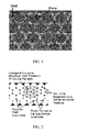
Figure 1 is an illustration of the pores and voids present in at least some parts of the hollow fiber membrane according to the present invention, showing a first set of pores having connecting outer rims (one pore highlighted in dashed lines), and a second set of pores (one pore highlighted in solid line) located in the connecting outer rims of the first set of pores. -
Figure 2 illustrates hexagonal packing of the first set of pores (formed by dissolving of particles) in a membrane according to an embodiment of the invention, wherein the hexagonal packing is 74 volume percent.Figure 2 also illustrates the matrix ("polymer formed interstitials") supporting the first set of pores, and the second set of pores connecting the outer rims of the first set of pores. -
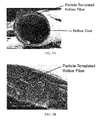
Figure 3A depicts an SEM of a single zone PES hollow fiber membrane in accordance with an embodiment of the invention illustrated in Example 3.Figure 3B is a higher magnification SEM of the hollow fiber membrane depicted inFigure 3A .Figure 3C is an even higher magnification SEM of the hollow fiber membrane. -
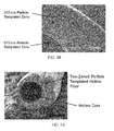
Figure 4A depicts an SEM of a double zone PES hollow fiber membrane in accordance with an embodiment of the invention illustrated in Example 4.Figure 4B is a higher magnification SEM of the hollow fiber membrane showing the two porous zones. -
Figure 5A depicts an SEM of a double zone PES hollow fiber membrane in accordance with an embodiment of the invention illustrated in Example 5.Figure 5B is a higher magnification SEM of the hollow fiber membrane showing the two porous zones.Figure 5C is an even higher magnification SEM of the hollow fiber membrane. - An embodiment of the invention provides a hollow fiber membrane comprising (i) an inner surface; (ii) an outer surface; and (iii) a porous bulk disposed between the inner surface and the outer surface, wherein the porous bulk comprises at least a first region including: a) a first set of pores having a first controlled pore size and having outer rims; b) a second set of pores connecting the outer rims of the first set of pores, wherein the pore size of the first set of pores is greater than the pore size of the second set of pores; and c) a polymer matrix supporting the first set of pores.
- In accordance with an embodiment, the pore size of the first set of pores is in the range of from about 50 nm to about 1000 nm, for example, from about 160 nm to about 630 nm. Thus, for example, the pore size of the first set of pores is about 160 nm, about 180 nm, about 200 nm, about 220 nm, about 240 nm, about 260 nm, about 280 nm, about 300 nm, about 320 nm, about 340 nm, about 360 nm, about 380 nm, about 400 nm, about 420 nm, about 440 nm, about 460 nm, about 480 nm, about 500 nm, about 520 nm, about 540 nm, about 560 nm, about 580 nm, about 600 nm, or about 620 nm.
- In an embodiment, the pore size of the second set of pores is in a ratio in the range of about 0.2 to about 0.4 times the pore size of the corresponding first set of pores.
- In an embodiment, the invention provides a hollow fiber membrane comprising (i) an inner surface; (ii) an outer surface; and (iii) a porous bulk disposed between the inner surface and the outer surface, wherein the porous bulk comprises a first region and a second region, wherein the first region includes: a) a first set of pores having outer rims; b) a second set of pores connecting the outer rims of the first set of pores, wherein the pore size of the first set of pores is greater than the pore size of the second set of pores, and the second region includes a) a third set of pores having outer rims; b) a fourth set of pores connecting the outer rims of the third set of pores, wherein the pore size of the third set of pores is greater than the pore size of the fourth set of pores and c) a polymer matrix supporting the third set of pores.
- In an embodiment, the pore size of the fourth set of pores is in a ratio in the range of about 0.2 to about 0.4 times the pore size of the third set of pores.
- In an embodiment, the pore size of the third set of pores is at least 10%, for example, 20%, 30%, 40%, 50%, 60%, 70%, or 80%, different from the pore size of the first set of pores. The pore size of the third set of pores can be larger or smaller than the pore size of the first set of pores.
- The present invention further provides a method of making a hollow fiber membrane, the method comprising: (a) forming at least one coating composition comprising a solvent, dissolvable nanoparticles, and a membrane-forming polymer; (b) coating the at least one coating composition onto a filament; (c) carrying out phase inversion of the coating composition or coating compositions coated onto the filament; (d) dissolving the dissolvable nanoparticles and removing the filament from the coated filament to obtain a hollow fiber membrane; and optionally (e) washing the hollow fiber membrane obtained in (d).
- In an embodiment, the hollow fiber membrane is prepared by introducing dissolvable nanoparticles into one or more membrane forming polymers (typically, the membrane forming polymers are dissolved in a solvent), casting the nanoparticle-containing polymer solution (coating composition) (preferably, casting the nanoparticle-containing polymer solution on a substrate such as a filament or fiber wherein the substrate has been pretreated with a preconditioning or releasing agent; more preferably, wherein the agent has been dried on the substrate before casting the solution thereon), carrying out phase inversion of the nanoparticle-containing polymer solution to provide a membrane, subsequently dissolving the nanoparticles, and washing the resultant membrane. Preferably, the dissolvable nanoparticles comprise silica nanoparticles, especially ones having high surface area or low density.
- Advantageously, hollow fiber membranes according to the invention can be produced using preformed polymers such as polyethersulfone (PES), polyvinylidene fluoride (PVDF), and polyacrylonitrile (PAN), that are commonly used in commercial membranes. Additionally, the nanoparticles can be dissolved without using hydrofluoric acid, for example, the nanoparticles can be dissolved using safer, more environmentally benign solvents such as an alkaline solution.
- In other embodiments, filters and filter devices are provided, the filter and filter devices comprising at least one hollow fiber membrane.
- A method of filtering fluid is also provided in accordance with another embodiment of the invention, the method comprising passing the fluid through at least one membrane, or a filter comprising at least one membrane, as described above.
- In accordance with an embodiment of the invention, a method of preparing a membrane comprises (a) forming a composition comprising a silica nanoparticle-containing polymer solution; (b) coating the composition onto a filament substrate; (c) carrying out phase inversion of the coated nanoparticle-containing coating composition to provide a membrane; (d) dissolving the nanoparticles and obtaining a nanoparticle-depleted membrane; and (e) removing the filament substrate to obtain the hollow fiber membrane. Preferably (b) comprises casting the solution onto a filament substrate pretreated with a preconditioning agent or a release agent. In some embodiments of the method, the preconditioning agent or the release agent is dried on the substrate before casting the solution on the pretreated substrate. In some embodiments, (c) comprises immersing the coated filament in liquid to obtain the membrane. Alternatively, or in addition, the coated filament can be phase inverted by exposing it to a temperature in the range of from about 40 °C to about 80 °C for a period in the range of from about 1 minute to about 2 hours.
- As will be described in more detail below, dissolving the particles creates a first set of pores in the membranes, the first set of pores having outer rims, and located within the outer rims is a second set of pores. As illustrated in
Figure 1 , the dashed line highlights an outer rim of a pore in the first set, and the solid line highlights a pore in the second set. The second set of pores allows communication (e.g., fluid flow) from the void within one outer rim into the void of another outer rim. - A variety of dissolvable nanoparticles are suitable for use in preparing membranes according to embodiments of the invention. Preferably, the nanoparticles comprise silica, typically ranging in diameter from about 50 nm to about 1000 nm. In accordance with an embodiment, the silica nanoparticles have a diameter of about 50 nm to about 1000 nm and a particle density of about 1.96 g/cm3 or less.
- In an embodiment, the silica nanoparticles have a particle density of about 1.93 to about 1.96 g/cm3.
- The silica nanoparticles can have a particle size, e.g., diameter, of less than 1000 nm, in particular a particle size of from about 160 nm to about 630 nm. Thus, for example, the nanoparticles have a particle size of about 160 nm, about 180 nm, about 200 nm, about 220 nm, about 240 nm, about 260 nm, about 280 nm, about 300 nm, about 320 nm, about 340 nm, about 360 nm, about 380 nm, about 400 nm, about 420 nm, about 440 nm, about 460 nm, about 480 nm, about 500 nm, about 520 nm, about 540 nm, about 560 nm, about 580 nm, about 600 nm, or about 620 nm.
- The silica nanoparticles can be prepared by a method comprising: (a) reacting an orthosilicate and an alcohol or a mixture of alcohols in an aqueous medium in the presence of a salt of a metal of Group Ia or Group IIa, or in the presence of a metalloid compound, optionally in combination with ammonium hydroxide, (b) isolating the resulting nanoparticles, and (c) treating the nanoparticles from (b) with an acid.
- In an embodiment, the nanoparticles can be included in the coating composition prior to the acid treatment (c).
- In an embodiment, the orthosilicate used in the preparation of the nanoparticles is a tetraalkylorthosilicate. Examples of tetraalkylorthosilicates tetramethylorthosilicate, tetraethylorthosilicate, tetrapropylorthosilicate, tetrabutylorthosilicate, and tetrapentylortho silicate.
- Any suitable alcohol or mixture of alcohols can be used in the preparation of the nanoparticles, for example, the alcohol or mixture of alcohols is selected from methanol, ethanol, propanol, butanol, and mixtures thereof.
- The salt of the metal used in the preparation of the nanoparticles can be selected from salts of lithium, sodium, potassium, cesium, magnesium, and calcium. In an embodiment, the salt of the metal is selected from lithium acetate, sodium acetate, sodium metasilicate, sodium formate, potassium acetate, cesium acetate, magnesium acetate, and calcium acetate. In another embodiment, the metalloid compound is a compound of boron, for example, boric acid or a boric acid ester such as alkyl borate. The alkyl borate can be a trialkyl borate such as trimethyl borate or triethyl borate.
- The acid employed in (c) of the method above can be a mineral acid or organic acid. Examples of mineral acids include hydrochloric acid, sulfuric acid, and nitric acid, preferably hydrochloric acid or sulfuric acid. Examples of organic acids include acetic acid, formic acid, trifluoroacetic acid, trichloroacetic acid, and p-toluenesulfonic acid, preferably formic acid. The nanoparticles isolated in (b) can be treated with a 1N to 2N acid, e.g., 1N HC1, for a period of about 0.5 hr to about 3 hr, preferably about 1 hr to 2 hr. For example, the nanoparticles can be sonicated in an acid bath for the above period. Following the acid treatment, the nanoparticles are isolated from the acid and washed with deionized water and dried under vacuum to obtain the silica nanoparticles.
- Illustratively, silica nanoparticles were prepared as follows. In a 6 L jacketed flask kept at 25 °C, 4.8 g lithium acetate dihydrate (LiOAc. 2H2O), 2480 mL deionized water (DI-H2O), 2.9 L anhydrous ethanol (EtOH), and 120 mL 28% w/w NH3 in water were stirred for 30 min at 200 rpm using an overhead mixer with PTFE impellers. A solution of 300 mL EtOH with 200 mL tetraethylorthosilicate (TEOS), which was prepared under dry conditions (< 10% relative humidity), was rapidly poured into the 6 L flask, and mixing was increased to 400 rpm and a dry air purge (< 1% relative humidity) was utilized for 5 min. Mixing was reduced to 200 rpm, the dry air purge was removed, the flask was sealed, and the reaction continued for a total of 1 h. The particles were purified by centrifugation and re-suspension in EtOH three times. The particles prepared as above can be used as such in the preparation of the coating composition for preparing the hollow fiber membrane, or alternatively, they can be treated with HC1 before preparing the coating composition.
- Thus, the particles were sonicated with 1N HC1, washed with DI water, and dried under vacuum at 40 °C.
- Typical coating compositions (dispersions) comprising the dissolvable nanoparticles, preferably purified dissolvable nanoparticles, comprise the nanoparticles dispersed at concentrations in the range of from about 30 wt% to about 65 wt% dimethyl formamide (DMF), within the range of from about 0.001 % to about 0.1 % triethanolamine (TEA).
- A membrane-forming polymer solution is prepared by dissolving the polymer in a solvent or a mixture of solvents. A variety of polymers is suitable for use as membrane-forming polymers in the invention, and is known in the art. Suitable polymers can include, polymers such as, for example, polyaromatics; sulfones (e.g., polysulfones, including aromatic polysulfones such as, for example, polyethersulfone (PES), polyether ether sulfone, bisphenol A polysulfone, polyarylsulfone, and polyphenylsulfone), polyamides, polyimides, polyvinylidene halides (including polyvinylidene fluoride (PVDF)), polyolefins, such as polypropylene and polymethylpentene, polyesters, polystyrenes, polycarbonates, polyacrylonitriles ((PANs) including polyalkylacrylonitriles), cellulosic polymers (such as cellulose acetates and cellulose nitrates), fluoropolymers, and polyetherether ketone (PEEK). Polymer solutions can include a mixture of polymers, e.g., a hydrophobic polymer (e.g., a sulfone polymer) and a hydrophilic polymer (e.g., polyvinylpyrrolidone (PVP)).
- In addition to one or more polymers, typical polymer solutions comprise at least one solvent, and may further comprise at least one non-solvent. Suitable solvents include, for example, dimethyl formamide (DMF); N,N-dimethylacetamide (DMAC); N-methyl pyrrolidone (NMP); dimethyl sulfoxide (DMSO), methyl sulfoxide, tetramethylurea; dioxane; diethyl succinate; chloroform; and tetrachloroethane; and mixtures thereof. Suitable nonsolvents include, for example, water; various polyethylene glycols (PEGs; e.g., PEG-200, PEG-300, PEG-400, PEG-1000); various polypropylene glycols; various alcohols, e.g., methanol, ethanol, isopropyl alcohol (IPA), amyl alcohols, hexanols, heptanols, and octanols; alkanes, such as hexane, propane, nitropropane, heptanes, and octane; and ketone, ethers and esters such as acetone, butyl ether, ethyl acetate, and amyl acetate; acids, such as acetic acid, citric acid, and lactic acid; and various salts, such as calcium chloride, magnesium chloride, and lithium chloride; and mixtures thereof.
- If desired, a solution comprising a polymer can further comprise, for example, one or more polymerization initiators (e.g., any one or more of peroxides, ammonium persulfate, aliphatic azo compounds (e.g., 2,2'-azobis(2-amidinopropane) dihydrochloride (V50)), and combinations thereof), and/or minor ingredients such as surfactants and/or release agents.
- Typical stock solutions including a polymer (before combining with a solution comprising the dissolvable nanoparticles) comprise in the range of from about 10 wt% to about 35 wt% resin (e.g., PES, PVDF, or PAN), in the range of from about 0 to about 10 wt% PVP, in the range of from about 0 to about 10 wt% PEG, in the range of from about 0 to about 90 wt% NMP, in the range of from about 0 to about 90 wt% DMF, and in the range of from about 0 to about 90 wt% DMAC.
- Suitable components of solutions are known in the art. Illustrative solutions comprising polymers, and illustrative solvents and nonsolvents include those disclosed in, for example,
U.S. Patents 4,340,579 ;4,629,563 ;4,900,449 ;4,964,990 ,5,444,097 ;5,846,422 ;5,906,742 ;5,928,774 ;6,045,899 ;6,146,747 ; and7,208,200 . - While a variety of polymeric membranes can be produced in accordance with the invention, in preferred embodiments, the membranes are sulfone membranes (more preferably, polyethersulfone membranes and/or polyarylsulfone membranes), acrylic membranes (e.g., (PANs, including polyalkylacrylonitriles), or semi-crystalline membranes (for example, PVDF membranes and/or polyamide membranes).
- The coating composition can be coated on a filament by any suitable technique, for example, by dip coating or spray coating.
- A variety of filaments are suitable for coating the coating composition according to embodiments of the invention. Suitable filaments include, for example, glass, a polyester such as polyethylene terephthalate (PET); polypropylene; polyethylene (including polyethylene naphthalate (PEN); polyethylene terephthalate glycol (PETG)); polyimide; polyphenylene oxide; nylons, particularly polycaprolactam; and acrylics. Preferably, the filament is a monofilament. The filament can be of any suitable thickness depending on the desired inner diameter of the hollow fiber membrane. The filaments are typically circular in cross-section and about 0.1 mil to about 10 mils thick, for example, 1, 2, 3, 4, 5, 6, 7, 8, 9, or 10 mils thick.
- In some embodiments, the filament has been preconditioned with a preconditioning agent, preferably, wherein the agent is dried before the particle-containing polymer solution (coating composition) is cast on the pretreated filament. Without being bound to any particular theory, it is believed that, with respect to some filaments, the use of a preconditioning agent improves efficiency in separating the hollow fiber membrane from the filament.
- Preferably, the preconditioning agent does not dissolve in solvents used in the coating compositions, is compatible with membrane processing temperatures, sufficiently adheres to the coating during thermal processing that it does not delaminate, and dissolves readily in solvents that do not dissolve the membrane resin (such that the membrane can be released from the filament). Examples of suitable preconditioning agents include polyvinyl alcohol (PVOH), polyvinylpyrrolidone (PVP), poly(acrylic acid), and poly(methacrylic acid).
- Illustratively, a PVOH stock solution can be prepared with about 5 wt% to about 15 wt% PVOH in deionized water, and cast on a filament by dipping the filament in the solution and withdrawing it to provide a coating having a thickness in the range of from about 1 to about 10 mil, and dried in an oven at a temperature in the range of from about 40 °C to about 80 °C for a period in the range of from about 1 minute to about 2 hours.
- The preconditioned filament is coated with the coating composition to provide the desired coating thickness.
- The coated filament is then subjected to a phase inversion process, which involves drying the coating containing resin(s), solvent system, and nanoparticles to remove some or all of the solvent. The coated filament can be dried, for example, by placing it in an oven at 40 to 80 C for a period of 1 min to about 2 hours. If desired, one or more additional coating compositions can be coated and dried in a similar manner on the filament that has been already coated and dried with the first coating composition. In an embodiment, the membrane-forming polymer in the first coating composition is different from the membrane-forming polymer in the second coating composition. In an embodiment, the solvent in the first coating composition is different from the solvent in the second coating composition.
- In an embodiment, the particle size of the dissolvable nanoparticles in the first coating composition is different from the particle size of the dissolvable nanoparticles in the second coating composition. Thus, the dissolvable nanoparticles in the first coating composition can be larger or smaller than the particle size of the dissolvable nanoparticles in the second coating composition.
- The filament that has been coated and dried as described above is then immersed in water for a suitable period of time, for example, 1 min to about 1 hr, thereby completing the solvent removal process.
- The dissolvable particles are then removed by dissolving them in a suitable solvent. A variety of procedures are suitable for dissolving the particles. As noted above, the process should avoid using hydrofluoric acid; rather, the nanoparticles can be, and should be, dissolved using safer, more environmentally benign solvents. For example, the filament that has been coated and phase inverted can be placed in a mineral acid (e.g., HCl or H2SO4) at a concentration in the range of about 0.1 to about 2 moles/L for a period in the range of from about 1 minute to about 1 hour, followed by immersion in an alkaline solution (e.g., KOH or NaOH) at a concentration in the range of about 0.1 to about 4 moles/L for a period in the range of from about 30 minutes to about 24 hours, followed by washing in water (e.g., DI water) for a period in the range of about 30 minutes to about 4 hours. If desired, the resulting membrane can subsequently be dried, e.g., in an oven at a temperature in the range of from about 40 °C to about 80 °C for a period in the range of about 30 minutes to about 2 hours.
- The filament is then removed from the above membrane by dissolving it in a suitable solvent. Any suitable solvent can be utilized which does not adversely affect the membrane. For example, formic acid can be used to dissolve a filament made of polycaprolactam. The resulting hollow fiber membrane is then washed with water for a suitable period of time, for example, 30 min to about 4 hr, and then dried, for example, in an oven at about 40 °C to about 80 °C for a period of about 30 min to about 2 hours.
- The hollow fiber membranes have a desirable hexagonal structure in at least small regions, resulting from the first set of pores in the bulk of the membrane. As illustrated in
Figure 2 (showing the first set of pores resulting from dissolving the introduced particles and the hexagonal structure representing the maximum void fraction), the maximum void fraction is 74 volume percent, and membranes according to embodiments of the invention have in the range of from about 66% to about 73% void fraction. - The surfaces of the hollow fiber membranes can have any suitable mean pore size, e.g., as determined by, for example, calculating the average surface pore size from an SEM at 5,000X or 20,000X magnification.
- Typically, the wall thickness of the hollow fiber membranes according to embodiments of the invention is in the range of about 0.5 mils to about 6.5 mils, preferably, in the range of from about 1 mils to about 3 mils.
- The membrane can have any desired critical wetting surface tension (CWST, as defined in, for example,
U.S. Patent 4,925,572 ). The CWST can be selected as is known in the art, e.g., as additionally disclosed in, for example,U.S. Patents 5,152,905 ,5,443,743 ,5,472,621 , and6,074,869 . Typically, the membrane has a CWST of greater than about 70 dynes/cm (about 70 x 10-5 N/cm), more typically greater than about 73 dynes/cm (about 73 x 10-5 N/cm), and can have a CWST of about 78 dynes/cm (about 78 x 10-5 N/cm) or more. In some embodiments, the membrane has a CWST of about 82 dynes/cm (about 82 x 10-5 N/cm) or more. - The surface characteristics of the hollow fiber membrane can be modified (e.g., to affect the CWST, to include a surface charge, e.g., a positive or negative charge, and/or to alter the polarity or hydrophilicity of the surface) by wet or dry oxidation, by coating or depositing a polymer on the surface, or by a grafting reaction. Modifications include, e.g., irradiation, a polar or charged monomer, coating and/or curing the surface with a charged polymer, and carrying out chemical modification to attach functional groups on the surface. Grafting reactions may be activated by exposure to an energy source such as gas plasma, vapor plasma, corona discharge, heat, a Van de Graff generator, ultraviolet light, electron beam, or to various other forms of radiation, or by surface etching or deposition using a plasma treatment.
- A variety of fluids can be filtered in accordance with embodiments of the invention. Hollow fiber membranes according to embodiments of the invention can be used in a variety of applications, including, for example, diagnostic applications (including, for example, sample preparation and/or diagnostic lateral flow devices), ink jet applications, filtering fluids for the pharmaceutical industry, filtering fluids for medical applications (including for home and/or for patient use, e.g., intravenous applications, also including, for example, filtering biological fluids such as blood (e.g., to remove leukocytes)), filtering fluids for the electronics industry (e.g., filtering photoresist fluids in the microelectronics industry), filtering fluids for the food and beverage industry, clarification, filtering antibody- and/or protein-containing fluids, filtering nucleic acid-containing fluids, cell detection (including in situ), cell harvesting, and/or filtering cell culture fluids. Alternatively, or additionally, membranes according to embodiments of the invention can be used to filter air and/or gas and/or can be used for venting applications (e.g., allowing air and/or gas, but not liquid, to pass therethrough). Membranes according to embodiments of the inventions can be used in a variety of devices, including surgical devices and products, such as, for example, ophthalmic surgical products.
- In accordance with embodiments of the invention, the hollow fiber membrane can be configured in a variety of configurations, e.g., the hollow fiber membrane can be arranged into bundles, sometimes with one end blinded.
- Hollow fiber membranes according to embodiments of the invention are typically disposed in a housing comprising at least one inlet and at least one outlet and defining at least one fluid flow path between the inlet and the outlet, wherein at least one inventive membrane or a filter including at least one inventive membrane is across the fluid flow path, to provide a filter device or filter module. In an embodiment, a filter device is provided comprising a housing comprising an inlet and a first outlet, and defining a first fluid flow path between the inlet and the first outlet; and at least one inventive hollow fiber membrane or a filter comprising at least one inventive membrane, the inventive membrane or filter comprising at least one inventive membrane being disposed in the housing across the first fluid flow path.
- Preferably, for crossflow applications, at least one inventive membrane or filter comprising at least one inventive membrane is disposed in a housing comprising at least one inlet and at least two outlets and defining at least a first fluid flow path between the inlet and the first outlet, and a second fluid flow path between the inlet and the second outlet, wherein the inventive membrane or filter comprising at least one inventive membrane is across the first fluid flow path, to provide a filter device or filter module. In an illustrative embodiment, the filter device comprises a crossflow filter module, the housing comprising an inlet, a first outlet comprising a concentrate outlet, and a second outlet comprising a permeate outlet, and defining a first fluid flow path between the inlet and the first outlet, and a second fluid flow path between the inlet and the second outlet, wherein at least one inventive membrane or filter comprising at least one inventive membrane is disposed across the first fluid flow path.
- The filter device or module may be sterilizable. Any housing of suitable shape and providing an inlet and one or more outlets may be employed.
- The housing can be fabricated from any suitable rigid impervious material, including any impervious thermoplastic material, which is compatible with the fluid being processed. For example, the housing can be fabricated from a metal, such as stainless steel, or from a polymer, e.g., transparent or translucent polymer, such as an acrylic, polypropylene, polystyrene, or a polycarbonate resin.
- The following examples further illustrate the invention but, of course, should not be construed as in any way limiting its scope.
- This example demonstrates methods for making the conditioned substrate, resin stock solutions, and nanoparticle stock solutions.
- PVOH stock solution (1): In a jacketed kettle kept at 90 °C, a solution was prepared by combining 10% w/w PVOH (96% Hydrolyzed, Scientific Polymer Products) with 90% deionized water and stirring at 200 rpm for 16 h. A polycaprolactam monofilament with a diameter of 1.5 mils was dipped into PVOH stock solution (1) and placed in an oven at 80 °C for 2h.
- Resin Stock Solution (1): In a jacketed kettle kept at 40 °C using a circulating bath, 30% (w/w) PES resin (BASF, Ultrason E 6020 P), 15% N-methylpyrrolidone, and 55% dimethylformamide were mixed at 800 rpm using an overhead mixer for 4 h. The solution was placed under vacuum at 200 mbar for 30 minutes to deaerate the solution.
- Particle Stock Solution (1): In a jacketed flask kept at 25 °C, a solution was prepared consisting of 1 mol/L ammonia, 8.24 mol/L ethanol, 1 mol/L methanol, 23.7 mol/L water, 0.15 mol/L tetraethoxysilane, and 0.0078 mol/L sodium metasilicate and stirred at 200 rpm for 1 h. Dynamic light scattering and SEM showed particle diameters of approximately 570 nm. The particles were centrifuged, decanted, and re-suspended in ethanol twice. They were centrifuged, decanted, and re-suspended in dimethylformamide along with 0.1% triethanolamine three times. The stock solution had a final concentration of 63% (w/w) particles.
- Particle Stock Solution (2): In a jacketed flask kept at 25 °C, a solution was prepared consisting of 0.9 mol/L ammonia, 9.16 mol/L ethanol, 23.07 mol/L water, 0.15 mol/L tetraethoxysilane, and 0.0078 mol/L lithium acetate and stirred at 200 rpm for 1 h. Dynamic light scattering and SEM show particle diameters of approximately 310 nm. The particles were centrifuged, decanted, and re-suspended in ethanol twice. They were centrifuged, decanted, and re-suspended in dimethylformamide along with 0.1% triethanolamine three times. The stock solution had a final concentration of 55% (w/w) particles.
- This example illustrates the preparation of coating compositions used in the preparation of the hollow fiber membranes.
- Coating composition (1): Resin stock solution (1) and particle stock solution (1) were combined in a flask_along with PEG-1000 and PVP K90 and mixed at 30,000 rpm for 2 min with final concentrations of 40% (w/w) particles, 11% PES, 0.5 % PEG-1000, 0.5 % PVP K90, 6% NMP, and 42% DMF. It was then deaerated at 200 mbar for 30 min.
- Coating composition (2): Resin stock solution (1) and particle stock solution (2) were combined in a flask along with PEG-1000 and PVP K90 and mixed at 30,000 rpm for 2 min with final concentrations of 42% (w/w) particles, 11% PES, 0.5 % PEG-1000, 0.5 % PVP K90, 5% NMP, and 41% DMF. It was then deaerated at 200 mbar for 30 min.
- This example illustrates a method of preparing a PES hollow fiber with one 570 nm particle-templated zone.
- The monofilament was dipped into coating composition (1) and placed in an oven for 15 min at 60 °C, followed by immersion immersed in water at 80 °C for 1 h. The coated filament was soaked in 1 mol/L HCl for 30 min, then 2 mol/L KOH for 18 h and the filament removed by soaking in formic acid for 18 h. The hollow fiber membrane was then washed with water at 25 °C for 2 h and dried at 70 °C for 30 min. An SEM image of the cross-section is shown in
Figure 4 . The first set of pores is about 570 nm, and the second set of pores is about 171 nm in diameter. - This example illustrates a method of preparing a PES hollow fiber with two particle-templated zones: 310 nm: 570 nm
- The monofilament was dipped into coating composition (1) and placed in an oven for 15 min at 60 °C, followed by dipping in coating composition (2) and placing in an oven for 15 min at 60 °C. The coated filament was then immersed in water at 80 °C for 1 h and soaked in 1 mol/L HCl for 30 min, then 2 mol/L KOH for 18 h. The filament was removed by soaking in formic acid for 18 h. The hollow fiber was then washed with water at 25 °C for 2 h and dried at 70 °C for 30 min. SEM images of the cross-sections are shown in
Figure 2 . The first set of pores in the inner region is about 310 nm, and the second set of pores is about 93 nm in diameter. The first set of pores in the outer region is about 570 nm, and the second set of pores is about 171 nm in diameter. - This example illustrates a method of preparing a PES hollow fiber with two particle-templated zones: 570 nm: 310 nm
- The monofilament was dipped into coating composition (2) and placed in an oven for 15 min at 60 °C, followed by dipping in coating composition (1) and placing in an oven for 15 min at 60 °C. The coated filament was then immersed in water at 80 °C for 1 h and soaked in 1 mol/L HCl for 30 min, then 2 mol/L KOH for 18 h. The core filament was removed by soaking in formic acid for 18 h. The hollow fiber was then washed with water at 25 °C for 2 h and dried at 70 °C for 30 min. SEM images of the cross-sections are shown in
Figure 3 . The first set of pores in the inner region is about 570 nm, and the second set of pores is about 171 nm in diameter. The first set of pores in the outer region is about 310 nm, and the second set of pores is about 93 nm in diameter. - All references, including publications, patent applications, and patents, cited herein are hereby incorporated by reference to the same extent as if each reference were individually and specifically indicated to be incorporated by reference and were set forth in its entirety herein.
- The use of the terms "a" and "an" and "the" and "at least one" and similar referents in the context of describing the invention (especially in the context of the following claims) are to be construed to cover both the singular and the plural, unless otherwise indicated herein or clearly contradicted by context. The use of the term "at least one" followed by a list of one or more items (for example, "at least one of A and B") is to be construed to mean one item selected from the listed items (A or B) or any combination of two or more of the listed items (A and B), unless otherwise indicated herein or clearly contradicted by context. The terms "comprising," "having," "including," and "containing" are to be construed as open-ended terms (i.e., meaning "including, but not limited to,") unless otherwise noted. Recitation of ranges of values herein are merely intended to serve as a shorthand method of referring individually to each separate value falling within the range, unless otherwise indicated herein, and each separate value is incorporated into the specification as if it were individually recited herein. All methods described herein can be performed in any suitable order unless otherwise indicated herein or otherwise clearly contradicted by context. The use of any and all examples, or exemplary language (e.g., "such as") provided herein, is intended merely to better illuminate the invention and does not pose a limitation on the scope of the invention unless otherwise claimed. No language in the specification should be construed as indicating any non-claimed element as essential to the practice of the invention.
- Preferred embodiments of this invention are described herein, including the best mode known to the inventors for carrying out the invention. Variations of those preferred embodiments may become apparent to those of ordinary skill in the art upon reading the foregoing description. The inventors expect skilled artisans to employ such variations as appropriate, and the inventors intend for the invention to be practiced otherwise than as specifically described herein. Accordingly, this invention includes all modifications and equivalents of the subject matter recited in the claims appended hereto as permitted by applicable law. Moreover, any combination of the above-described elements in all possible variations thereof is encompassed by the invention unless otherwise indicated herein or otherwise clearly contradicted by context.
Claims (15)
- A hollow fiber membrane comprising:(i) an inner surface;(ii) an outer surface; and(iii) a porous bulk disposed between the inner surface and the outer surface, wherein the porous bulk comprises at least a first region including: a) a first set of pores having a first controlled pore size and having outer rims; b) a second set of pores connecting the outer rims of the first set of pores, wherein the pore size of the first set of pores is greater than the pore size of the second set of pores; and c) a polymer matrix supporting the first set of pores.
- The hollow fiber membrane of claim 1, wherein the pore size of the first set of pores is in the range of from about 50 nm to about 1000 nm.
- The hollow fiber membrane of claim 1 or 2, wherein the pore size of the second set of pores is in a ratio in the range of about 0.2 to about 0.4 times the pore size of the first set of pores.
- The hollow fiber membrane of claim 1 or 2, wherein the porous bulk further comprises at least a second region including: d) a third set of pores having outer rims; e) a fourth set of pores connecting the outer rims of the third set of pores, wherein the pore size of the third set of pores is greater than the pore size of the fourth set of pores; and (f) a polymer matrix supporting the third set of pores, optionally
wherein the pore size of the fourth set of pores is in a ratio in the range of about 0.2 to about 0.4 times the pore size of the third set of pores and/or
wherein the pore size of the third set of pores is at least 10% different from the pore size of the first set of pores. - A method of making a hollow fiber membrane, the method comprising:(a) forming at least one coating composition comprising a solvent, dissolvable silica nanoparticles, and a membrane-forming polymer;(b) coating the at least one coating composition onto a filament;(c) carrying out phase inversion of the coating composition or coating compositions coated onto the filament;(d) dissolving the dissolvable silica nanoparticles and removing the filament from the coated filament to obtain a hollow fiber membrane; and optionally(e) washing the hollow fiber membrane obtained in (d).
- The method of claim 5, which includes:forming a first coating composition and a second coating composition, each comprising a solvent, a set of dissolvable silica nanoparticles, and a membrane-forming polymer in (a), andcoating the coating the first and the second coating compositions onto the filament in (b).
- The method of claim 6, wherein the particle size of the dissolvable silica nanoparticles in the first coating composition is different from the particle size of the dissolvable silica nanoparticles in the second coating composition.
- The method of claim 6 or 7, wherein the membrane-forming polymer in the first coating composition is different from the membrane-forming polymer in the second coating composition.
- The method of any one of claims 5 to 7, wherein the solvent in the first coating composition is different from the solvent in the second coating composition.
- The method of any one of claims 5 to 9, wherein the filament is a polymer filament, optionally
wherein the polymer filament has been pre-treated with a release agent. - The method of any one of claims 5 to 10, wherein the at least one coating composition is coated by dip coating.
- The method of any one of claims 1 to 11, wherein the phase inversion is carried out by heating the coated filament.
- The method of any one of claims 1 to 12, wherein the dissolvable silica nanoparticles are dissolved by contacting the filament after (c) with an acid and an alkali.
- The method of any one of claims 1 to 13, wherein the filament is removed by dissolving it in a solvent.
- A method of filtering a fluid, the method comprising passing the fluid through the hollow fiber membrane of any one of claims 1 to 4 or a membrane obtained in a method according to any one of claims 5 to 14.
Applications Claiming Priority (1)
| Application Number | Priority Date | Filing Date | Title |
|---|---|---|---|
| US14/193,825 US9737860B2 (en) | 2014-02-28 | 2014-02-28 | Hollow fiber membrane having hexagonal voids |
Publications (2)
| Publication Number | Publication Date |
|---|---|
| EP2913098A1 true EP2913098A1 (en) | 2015-09-02 |
| EP2913098B1 EP2913098B1 (en) | 2024-05-22 |
Family
ID=52686074
Family Applications (1)
| Application Number | Title | Priority Date | Filing Date |
|---|---|---|---|
| EP15152939.3A Active EP2913098B1 (en) | 2014-02-28 | 2015-01-28 | Hollow fiber membrane having hexagonal voids |
Country Status (4)
| Country | Link |
|---|---|
| US (1) | US9737860B2 (en) |
| EP (1) | EP2913098B1 (en) |
| JP (2) | JP2015166078A (en) |
| CN (2) | CN104874299A (en) |
Families Citing this family (10)
| Publication number | Priority date | Publication date | Assignee | Title |
|---|---|---|---|---|
| US9302228B2 (en) | 2014-02-28 | 2016-04-05 | Pall Corporation | Charged porous polymeric membrane with high void volume |
| US9764292B2 (en) | 2014-02-28 | 2017-09-19 | Pall Corporation | Porous polymeric membrane with high void volume |
| US9610548B2 (en) | 2014-02-28 | 2017-04-04 | Pall Corporation | Composite porous polymeric membrane with high void volume |
| US9561473B2 (en) | 2014-02-28 | 2017-02-07 | Pall Corporation | Charged hollow fiber membrane having hexagonal voids |
| US9776142B2 (en) | 2014-02-28 | 2017-10-03 | Pall Corporation | Porous polymeric membrane with high void volume |
| US9446355B2 (en) | 2014-02-28 | 2016-09-20 | Pall Corporation | Porous polymeric membrane with high void volume |
| EP3398675A1 (en) * | 2017-05-02 | 2018-11-07 | Helmholtz-Zentrum Geesthacht Zentrum für Material- und Küstenforschung GmbH | Macroporous or mesoporous polymer films in hollow fiber or flat sheet geometry |
| EP3858471A1 (en) * | 2020-01-31 | 2021-08-04 | Novamem AG | Solvent-free production of porous polymer structures |
| US12606661B2 (en) | 2021-02-03 | 2026-04-21 | Donaldson Company, Inc. | Compositions and articles including perfluoropolyether bottlebrush polymers and methods of making and using same |
| US12296303B2 (en) * | 2021-11-03 | 2025-05-13 | Taiwan Semiconductor Manufacturing Company, Ltd. | Filter membrane and method for making the same |
Citations (20)
| Publication number | Priority date | Publication date | Assignee | Title |
|---|---|---|---|---|
| US4340579A (en) | 1978-12-02 | 1982-07-20 | Vereinigte Aluminium-Werke Aktiengesellschaft | Process for producing modified alumina hydrate crystals |
| US4629563A (en) | 1980-03-14 | 1986-12-16 | Brunswick Corporation | Asymmetric membranes |
| US4900449A (en) | 1987-05-20 | 1990-02-13 | Gelman Sciences | Filtration membranes and method of making the same |
| US4925572A (en) | 1987-10-20 | 1990-05-15 | Pall Corporation | Device and method for depletion of the leukocyte content of blood and blood components |
| US4964990A (en) | 1987-05-20 | 1990-10-23 | Gelman Sciences, Inc. | Filtration membranes and method of making the same |
| US5152905A (en) | 1989-09-12 | 1992-10-06 | Pall Corporation | Method for processing blood for human transfusion |
| US5443743A (en) | 1991-09-11 | 1995-08-22 | Pall Corporation | Gas plasma treated porous medium and method of separation using same |
| US5444097A (en) | 1992-07-07 | 1995-08-22 | Millipore Corporation | Porous polymeric structures and a method of making such structures by means of heat-induced phase separation |
| US5472621A (en) | 1992-06-10 | 1995-12-05 | Pall Corporation | Method for treating transition zone material |
| US5846422A (en) | 1994-03-04 | 1998-12-08 | Memtec America Corporation | Large pore synthetic polymer membranes |
| US5906742A (en) | 1995-07-05 | 1999-05-25 | Usf Filtration And Separations Group Inc. | Microfiltration membranes having high pore density and mixed isotropic and anisotropic structure |
| US5928774A (en) | 1997-07-08 | 1999-07-27 | Usf Filtration And Separations Group Inc. | Highly asymmetric ultrafiltration membranes |
| US6045899A (en) | 1996-12-12 | 2000-04-04 | Usf Filtration & Separations Group, Inc. | Highly assymetric, hydrophilic, microfiltration membranes having large pore diameters |
| US6074869A (en) | 1994-07-28 | 2000-06-13 | Pall Corporation | Fibrous web for processing a fluid |
| US6146747A (en) | 1997-01-22 | 2000-11-14 | Usf Filtration And Separations Group Inc. | Highly porous polyvinylidene difluoride membranes |
| EP1166859A2 (en) * | 2000-06-21 | 2002-01-02 | Kuraray Co., Ltd. | Porous hollow fiber membranes and method of making the same |
| US20030107150A1 (en) * | 2001-03-06 | 2003-06-12 | Katsuhiko Hamanaka | Method for producing hollow yarn film |
| US7208200B2 (en) | 2000-05-24 | 2007-04-24 | Millipore Corporation | Process of forming multilayered structures |
| EP2476724A1 (en) * | 2011-01-17 | 2012-07-18 | ETH Zurich | Pourous polymer membranes |
| US20130134081A1 (en) * | 2011-11-29 | 2013-05-30 | Samsung Electronics Co., Ltd. | Hybrid porous structure, method of preparing hybrid porous structure, separation membrane including hybrid porous structure, and water treatment device including membrane |
Family Cites Families (88)
| Publication number | Priority date | Publication date | Assignee | Title |
|---|---|---|---|---|
| US2913419A (en) | 1956-04-18 | 1959-11-17 | Du Pont | Chemical process and composition |
| US2974108A (en) | 1957-01-14 | 1961-03-07 | Du Pont | Aluminosilicate aquasols and their preparation |
| CA1047718A (en) | 1971-12-16 | 1979-02-06 | Robert E. Kesting | Microporous polyester membranes and polymer assisted phase inversion process for making same |
| US3957651A (en) | 1971-12-16 | 1976-05-18 | Chemical Systems Incorporated | Microporous polyester membranes and polymer assisted phase inversion process for their manufacture |
| US4188418A (en) | 1972-08-09 | 1980-02-12 | Lever Brothers Company | Separation process |
| CH625966A5 (en) | 1977-07-15 | 1981-10-30 | Kilcher Chemie Ag | |
| US4289600A (en) | 1978-03-31 | 1981-09-15 | Hooker Chemicals & Plastics Corp. | Microporous membrane materials |
| DE2829045A1 (en) | 1978-07-01 | 1980-01-10 | Degussa | PRESERVED FELLING ACID |
| JPS58110414A (en) | 1981-12-23 | 1983-07-01 | Tokuyama Soda Co Ltd | Inorganic oxide and its manufacture |
| JPH0611870B2 (en) * | 1986-06-27 | 1994-02-16 | 徳山曹達株式会社 | Inorganic compound / dye composite particles |
| US5236683A (en) | 1987-01-20 | 1993-08-17 | Mizusawa Industrial Chemicals, Ltd. | Amorphous silica spherical particles |
| US5221497A (en) | 1988-03-16 | 1993-06-22 | Nissan Chemical Industries, Ltd. | Elongated-shaped silica sol and method for preparing the same |
| US4940571A (en) | 1988-04-01 | 1990-07-10 | Gte Laboratories Incorporated | Method of making large particle size, high purity dense silica |
| JP2899903B2 (en) * | 1989-01-12 | 1999-06-02 | 旭化成工業株式会社 | Polyvinylidene fluoride porous membrane and method for producing the same |
| US5100581A (en) | 1990-02-22 | 1992-03-31 | Nissan Chemical Industries Ltd. | Method of preparing high-purity aqueous silica sol |
| US5024826A (en) | 1990-03-05 | 1991-06-18 | E. I. Du Pont De Nemours And Company | Silica particulate composition |
| US5102917A (en) | 1990-09-14 | 1992-04-07 | Cpc Engineering Corporation | Porous polysulfone media suitable for filtration |
| JP3255385B2 (en) * | 1993-12-15 | 2002-02-12 | 株式会社クラレ | Polysulfone hollow fiber membrane and method for producing the same |
| US5746916A (en) * | 1994-01-26 | 1998-05-05 | Mitsubishi Rayon Co., Ltd. | Microporous membrane made of non-crystalline polymers and method of producing the same |
| CA2509635C (en) | 1997-09-30 | 2007-11-20 | Nalco Chemical Company | Colloidal borosilicates and their use in the production of paper |
| US6083393A (en) | 1997-10-27 | 2000-07-04 | Pall Corporation | Hydrophilic membrane |
| US6255359B1 (en) * | 1997-12-23 | 2001-07-03 | Board Of Regents Of The University Of Texas System | Permeable compositions and methods for their preparation |
| CO5070714A1 (en) | 1998-03-06 | 2001-08-28 | Nalco Chemical Co | PROCESS FOR THE PREPARATION OF STABLE COLOIDAL SILICE |
| DE60011584T3 (en) | 1999-02-25 | 2008-03-06 | Pall Corp. | POSITIVE LOADED MEMBRANE |
| US6680013B1 (en) | 1999-04-15 | 2004-01-20 | Regents Of The University Of Minnesota | Synthesis of macroporous structures |
| US7838225B2 (en) | 1999-10-29 | 2010-11-23 | Hologic, Inc. | Methods for detection of a target nucleic acid by forming a cleavage structure using a reverse transcriptase |
| PT1261550E (en) | 2000-03-03 | 2006-05-31 | Grace Gmbh & Co Kg | PARTICLES OF SILICA AMORFA UNDERSTANDING BORO |
| US6548264B1 (en) | 2000-05-17 | 2003-04-15 | University Of Florida | Coated nanoparticles |
| JP3805634B2 (en) | 2000-06-21 | 2006-08-02 | 株式会社クラレ | Porous hollow fiber membrane and method for producing the same |
| US6906109B2 (en) | 2000-09-01 | 2005-06-14 | Chemical Products Corp. | Method for controling uniformity of colloidal silica particle size |
| DE10048616A1 (en) | 2000-09-30 | 2002-04-11 | Degussa | Doped precipitated silica |
| JP2002136851A (en) * | 2000-10-31 | 2002-05-14 | Asahi Kasei Corp | Ethylene-vinyl alcohol copolymer porous hollow fiber membrane and method for producing the same |
| US6929764B2 (en) | 2000-11-17 | 2005-08-16 | William Marsh Rice University | Polymers having ordered, monodisperse pores and their corresponding ordered, monodisperse colloids |
| DE10058258B4 (en) | 2000-11-23 | 2005-01-27 | Goedel, Werner Andreas | Porous membranes, their preparation and use |
| JP4666530B2 (en) | 2001-03-06 | 2011-04-06 | 旭化成ケミカルズ株式会社 | Method for producing hollow fiber membrane |
| JP2003093852A (en) | 2001-09-25 | 2003-04-02 | Sangaku Renkei Kiko Kyushu:Kk | Method for producing separation membrane and separation membrane forming material and separation membrane obtained thereby |
| TWI276604B (en) | 2001-12-27 | 2007-03-21 | Tokuyama Corp | Silica composite oxide particles and method of producing the same |
| DE10344819B4 (en) | 2003-09-26 | 2017-06-29 | Sartorius Stedim Biotech Gmbh | Adsorption membranes, methods of making the same and devices comprising the adsorption membranes |
| US7438875B2 (en) | 2003-10-16 | 2008-10-21 | Kimberly-Clark Worldwide, Inc. | Method for reducing odor using metal-modified silica particles |
| AU2003296868A1 (en) | 2003-12-31 | 2005-07-21 | Council Of Scientific And Industrial Research | A process for the preparation of free standing membranes |
| JP4564758B2 (en) * | 2004-01-09 | 2010-10-20 | 株式会社クラレ | Method for producing vinylidene fluoride resin porous membrane |
| JP2005205358A (en) * | 2004-01-26 | 2005-08-04 | Toray Ind Inc | Method for producing porous hollow fiber membrane |
| US20050234136A1 (en) | 2004-04-19 | 2005-10-20 | Holland Brian T | Colloidal compositions and methods of preparing same |
| CN1289176C (en) * | 2004-06-02 | 2006-12-13 | 中国科学院合肥物质科学研究院 | Shape-controllable ordered porous film material and preparation method |
| CN100509123C (en) * | 2004-06-02 | 2009-07-08 | 中国科学院合肥物质科学研究院 | Form-controllable transferable ordered through-hole film material and preparation method thereof |
| US20060283095A1 (en) | 2005-06-15 | 2006-12-21 | Planar Solutions, Llc | Fumed silica to colloidal silica conversion process |
| US8052788B2 (en) | 2005-08-10 | 2011-11-08 | Nalco Company | Method of producing silica sols with controllable broad size distribution and minimum particle size |
| EP1764116A1 (en) | 2005-09-16 | 2007-03-21 | Debiotech S.A. | Porous coating process using colloidal particles |
| KR101214060B1 (en) | 2005-09-26 | 2012-12-20 | 플레이너 솔루션즈 엘엘씨 | Ultrapure colloidal silica for use in chemical mechanical polishing applications |
| JP4563457B2 (en) * | 2005-10-13 | 2010-10-13 | 旭化成ケミカルズ株式会社 | Porous multilayer hollow fiber membrane and method for producing the same |
| WO2007045053A1 (en) | 2005-10-19 | 2007-04-26 | Vlaamse Instelling Voor Technologisch Onderzoek N.V. (Vito) | Zeolite-like membranes from nano-zeolitic particles |
| US7717271B2 (en) * | 2005-12-07 | 2010-05-18 | General Electric Company | Membrane structure and method of making |
| DE102006010831A1 (en) | 2006-03-07 | 2007-09-13 | Werner Andreas Goedel | Composite membrane, useful e.g. for filtration and as membrane reactor, comprises porous layer of hardened material and porous support structure, parts of which penetrate into the porous layer |
| DE102006036863B4 (en) | 2006-08-03 | 2008-10-16 | Technische Universität Chemnitz | Mechanically stable porous membrane, process for its preparation and its use |
| US7943543B1 (en) | 2006-09-29 | 2011-05-17 | Uop Llc | Ionic liquid-solid-polymer mixed matrix membranes for gas separations |
| US20080108497A1 (en) | 2006-11-08 | 2008-05-08 | Holland Brian T | Metal-rich siliceous compositions and methods of producing same |
| WO2009010945A2 (en) | 2007-07-13 | 2009-01-22 | University College Cork - National University Of Ireland, Cork | A method for synthesising microparticles |
| US20090149313A1 (en) | 2007-12-11 | 2009-06-11 | Chunqing Liu | Mixed Matrix Membranes Containing Low Acidity Nano-Sized SAPO-34 Molecular Sieves |
| TWI457283B (en) | 2008-02-12 | 2014-10-21 | Nissan Chemical Ind Ltd | Silica colloidal particles and production method thereof, and organic solvent-dispersed silica sol, polimerizable compound-dispersed silica sol and dicarboxylic anhydride-dispersed silica sol thereof |
| JP5042110B2 (en) | 2008-04-22 | 2012-10-03 | サルナス、ペトロニス | Production of nanopores |
| CN101417212B (en) * | 2008-11-21 | 2010-10-27 | 天津工业大学 | A kind of solution spinning preparation method of hollow fiber porous membrane |
| US8163388B2 (en) | 2008-12-15 | 2012-04-24 | Kimberly-Clark Worldwide, Inc. | Compositions comprising metal-modified silica nanoparticles |
| US20100155325A1 (en) | 2008-12-24 | 2010-06-24 | General Electric Company | Particle-templated membranes, and related processes for their preparation |
| EP2405999A2 (en) | 2009-03-13 | 2012-01-18 | President and Fellows of Harvard College | Systems and methods of templating using particles such as colloidal particles |
| JP5717720B2 (en) | 2009-04-15 | 2015-05-13 | コーネル ユニバーシティCornell University | Fluorescent silica nanoparticles improved by densification of silica |
| KR101213714B1 (en) | 2009-05-27 | 2012-12-18 | 한국세라믹기술원 | Preparation method for mesoporous silica nanoparticles using transition metal salt |
| WO2011063356A2 (en) | 2009-11-22 | 2011-05-26 | Sirnaomics, Inc. | Rare earth-doped up-conversion nanoparticles for therapeutic and diagnostic applications |
| US8845991B2 (en) | 2010-04-08 | 2014-09-30 | Ecolab Usa Inc. | Silica particle manufacturing process |
| US8932549B2 (en) | 2010-04-08 | 2015-01-13 | Ecolab Usa Inc. | Sulfur containing silica particle |
| CN102382247B (en) | 2010-09-03 | 2014-06-04 | 中国科学院过程工程研究所 | Preparation method of molecular imprinting polymer micro-sphere with uniform size and application |
| WO2012058154A2 (en) | 2010-10-27 | 2012-05-03 | University Of Florida Research Foundation, Inc. | Porous polymer membrances, methods of making, and methods of use |
| US8540800B2 (en) | 2011-03-21 | 2013-09-24 | Uop Llc | Microporous UZM-5 inorganic zeolite membranes for gas, vapor, and liquid separations |
| KR101880441B1 (en) * | 2011-07-21 | 2018-07-20 | 서울대학교산학협력단 | Method for Large-Scale Production of Uniform-Sized Silica Nanoparticles |
| US8840791B2 (en) | 2011-09-01 | 2014-09-23 | Pall Corporation | Multilayer microfiltration membrane |
| KR101852924B1 (en) | 2011-11-04 | 2018-04-30 | 삼성전자주식회사 | Hybrid porous structured material, membrane including the same and method of preparing hybrid porous structure material |
| JP2015504452A (en) | 2011-12-06 | 2015-02-12 | エンパイア テクノロジー ディベロップメント エルエルシー | Phosphorus loading particles and methods of preparing and using them |
| JP2013144264A (en) * | 2012-01-13 | 2013-07-25 | Nok Corp | Method for producing porous polysulfone-based membrane |
| WO2013130893A2 (en) | 2012-02-28 | 2013-09-06 | Massachusetts Institute Of Technology | Hierarchical porous membrane for emulsion separation |
| US9459188B2 (en) | 2012-03-16 | 2016-10-04 | Board Of Trustees Of Michigan State University | Functionalization of a porous membrane with an adsorbed polyacid |
| CN103386299B (en) | 2013-08-02 | 2016-03-30 | 天津工业大学 | A kind of non-woven group compound film for lithium isotope separation and preparation method thereof and the isotopic method of membrane chromatography separating Li |
| US9776142B2 (en) | 2014-02-28 | 2017-10-03 | Pall Corporation | Porous polymeric membrane with high void volume |
| US9764292B2 (en) | 2014-02-28 | 2017-09-19 | Pall Corporation | Porous polymeric membrane with high void volume |
| US9610548B2 (en) | 2014-02-28 | 2017-04-04 | Pall Corporation | Composite porous polymeric membrane with high void volume |
| US20150246320A1 (en) | 2014-02-28 | 2015-09-03 | Pall Corporation | Porous polymeric membrane with high void volume |
| US9446355B2 (en) | 2014-02-28 | 2016-09-20 | Pall Corporation | Porous polymeric membrane with high void volume |
| US9561473B2 (en) | 2014-02-28 | 2017-02-07 | Pall Corporation | Charged hollow fiber membrane having hexagonal voids |
| US9309126B2 (en) | 2014-02-28 | 2016-04-12 | Pall Corporation | Rapidly dissolvable nanoparticles |
| US9302228B2 (en) | 2014-02-28 | 2016-04-05 | Pall Corporation | Charged porous polymeric membrane with high void volume |
-
2014
- 2014-02-28 US US14/193,825 patent/US9737860B2/en active Active
-
2015
- 2015-01-28 EP EP15152939.3A patent/EP2913098B1/en active Active
- 2015-01-29 JP JP2015015071A patent/JP2015166078A/en active Pending
- 2015-01-30 CN CN201510184066.5A patent/CN104874299A/en active Pending
- 2015-01-30 CN CN201910508784.1A patent/CN110124528A/en active Pending
-
2017
- 2017-03-21 JP JP2017054579A patent/JP6351002B2/en active Active
Patent Citations (21)
| Publication number | Priority date | Publication date | Assignee | Title |
|---|---|---|---|---|
| US4340579A (en) | 1978-12-02 | 1982-07-20 | Vereinigte Aluminium-Werke Aktiengesellschaft | Process for producing modified alumina hydrate crystals |
| US4629563A (en) | 1980-03-14 | 1986-12-16 | Brunswick Corporation | Asymmetric membranes |
| US4629563B1 (en) | 1980-03-14 | 1997-06-03 | Memtec North America | Asymmetric membranes |
| US4900449A (en) | 1987-05-20 | 1990-02-13 | Gelman Sciences | Filtration membranes and method of making the same |
| US4964990A (en) | 1987-05-20 | 1990-10-23 | Gelman Sciences, Inc. | Filtration membranes and method of making the same |
| US4925572A (en) | 1987-10-20 | 1990-05-15 | Pall Corporation | Device and method for depletion of the leukocyte content of blood and blood components |
| US5152905A (en) | 1989-09-12 | 1992-10-06 | Pall Corporation | Method for processing blood for human transfusion |
| US5443743A (en) | 1991-09-11 | 1995-08-22 | Pall Corporation | Gas plasma treated porous medium and method of separation using same |
| US5472621A (en) | 1992-06-10 | 1995-12-05 | Pall Corporation | Method for treating transition zone material |
| US5444097A (en) | 1992-07-07 | 1995-08-22 | Millipore Corporation | Porous polymeric structures and a method of making such structures by means of heat-induced phase separation |
| US5846422A (en) | 1994-03-04 | 1998-12-08 | Memtec America Corporation | Large pore synthetic polymer membranes |
| US6074869A (en) | 1994-07-28 | 2000-06-13 | Pall Corporation | Fibrous web for processing a fluid |
| US5906742A (en) | 1995-07-05 | 1999-05-25 | Usf Filtration And Separations Group Inc. | Microfiltration membranes having high pore density and mixed isotropic and anisotropic structure |
| US6045899A (en) | 1996-12-12 | 2000-04-04 | Usf Filtration & Separations Group, Inc. | Highly assymetric, hydrophilic, microfiltration membranes having large pore diameters |
| US6146747A (en) | 1997-01-22 | 2000-11-14 | Usf Filtration And Separations Group Inc. | Highly porous polyvinylidene difluoride membranes |
| US5928774A (en) | 1997-07-08 | 1999-07-27 | Usf Filtration And Separations Group Inc. | Highly asymmetric ultrafiltration membranes |
| US7208200B2 (en) | 2000-05-24 | 2007-04-24 | Millipore Corporation | Process of forming multilayered structures |
| EP1166859A2 (en) * | 2000-06-21 | 2002-01-02 | Kuraray Co., Ltd. | Porous hollow fiber membranes and method of making the same |
| US20030107150A1 (en) * | 2001-03-06 | 2003-06-12 | Katsuhiko Hamanaka | Method for producing hollow yarn film |
| EP2476724A1 (en) * | 2011-01-17 | 2012-07-18 | ETH Zurich | Pourous polymer membranes |
| US20130134081A1 (en) * | 2011-11-29 | 2013-05-30 | Samsung Electronics Co., Ltd. | Hybrid porous structure, method of preparing hybrid porous structure, separation membrane including hybrid porous structure, and water treatment device including membrane |
Non-Patent Citations (11)
| Title |
|---|
| A.L. AHMAD ET AL: "Recent development in additives modifications of polyethersulfone membrane for flux enhancement", CHEMICAL ENGINEERING JOURNAL, vol. 223, 1 May 2013 (2013-05-01), pages 246 - 267, XP055197981, ISSN: 1385-8947, DOI: 10.1016/j.cej.2013.02.130 * |
| ANTJE WILKE ET AL: "Mesoporous Polymer Networks-Ultraporous DVB Resins by Hard-Templating of Close-Packed Silica Spheres", MACROMOLECULAR RAPID COMMUNICATIONS, vol. 33, no. 9, 14 May 2012 (2012-05-14), pages 785 - 790, XP055198463, ISSN: 1022-1336, DOI: 10.1002/marc.201100862 * |
| BYRON GATES ET AL: "Fabrication and Characterization of Porous Membranes with Highly Ordered Three-Dimensional Periodic Structures", CHEMISTRY OF MATERIALS, vol. 11, no. 10, 1 October 1999 (1999-10-01), pages 2827 - 2836, XP055200681, ISSN: 0897-4756, DOI: 10.1021/cm990195d * |
| CHRISTOPH R KELLENBERGER ET AL: "Soluble nanoparticles as removable pore templates for the preparation of polymer ultrafiltration membranes", JOURNAL OF MEMBRANE SCIENCE, ELSEVIER, vol. 387, 9 October 2011 (2011-10-09), pages 76 - 82, XP028118989, ISSN: 0376-7388, [retrieved on 20111013], DOI: 10.1016/J.MEMSCI.2011.10.011 * |
| DINGCAI WU ET AL: "Design and Preparation of Porous Polymers", CHEMICAL REVIEWS, vol. 112, no. 7, 11 July 2012 (2012-07-11), pages 3959 - 4015, XP055198477, ISSN: 0009-2665, DOI: 10.1021/cr200440z * |
| HAOQING H ET AL: "Poly(p-xylylene) Nanotubes by Coating and Removal of Ultrathin Polymer Template Fibers", MACROMOLECULES, AMERICAN CHEMICAL SOCIETY, US, vol. 35, no. 7, 26 March 2002 (2002-03-26), pages 2429 - 2431, XP002622573, ISSN: 0024-9297, [retrieved on 20020228], DOI: 10.1021/MA011607I * |
| LIU H Y ET AL: "A hard-template process to prepare three-dimensionally macroporous polymer electrolyte for lithium-ion batteries", ELECTROCHIMICA ACTA, ELSEVIER SCIENCE PUBLISHERS, BARKING, GB, vol. 121, 15 January 2014 (2014-01-15), pages 328 - 336, XP028663178, ISSN: 0013-4686, DOI: 10.1016/J.ELECTACTA.2014.01.013 * |
| MUELLER ET AL: "Preparation and mechanical characterization of artificial hollow tubes", POLYMER, ELSEVIER SCIENCE PUBLISHERS B.V, GB, vol. 48, no. 9, 14 April 2007 (2007-04-14), pages 2520 - 2525, XP022043328, ISSN: 0032-3861, DOI: 10.1016/J.POLYMER.2007.03.022 * |
| MUNAKATA ET AL: "Three-dimensionally ordered macroporous polyimide composite membrane with controlled pore size for direct methanol fuel cells", JOURNAL OF POWER SOURCES, ELSEVIER SA, CH, vol. 178, no. 2, 3 March 2008 (2008-03-03), pages 596 - 602, XP022509798, ISSN: 0378-7753, DOI: 10.1016/J.JPOWSOUR.2007.08.060 * |
| WEBER J ET AL: "Mesoporous poly(benzimidazole) networks via solvent mediated templating of hard spheres", MACROMOLECULES, AMERICAN CHEMICAL SOCIETY, US, vol. 40, 20 February 2007 (2007-02-20), pages 1299 - 1304, XP002660474, ISSN: 0024-9297, [retrieved on 20070124], DOI: 10.1021/MA062598M * |
| YOU Y ET AL: "Preparation of porous ultrafine PGA fibers via selective dissolution of electrospun PGA/PLA blend fibers", MATERIALS LETTERS, NORTH HOLLAND PUBLISHING COMPANY. AMSTERDAM, NL, vol. 60, no. 6, 1 March 2006 (2006-03-01), pages 757 - 760, XP027897845, ISSN: 0167-577X, [retrieved on 20060301] * |
Also Published As
| Publication number | Publication date |
|---|---|
| JP2015166078A (en) | 2015-09-24 |
| CN110124528A (en) | 2019-08-16 |
| EP2913098B1 (en) | 2024-05-22 |
| US20150246325A1 (en) | 2015-09-03 |
| CN104874299A (en) | 2015-09-02 |
| US9737860B2 (en) | 2017-08-22 |
| JP6351002B2 (en) | 2018-07-04 |
| JP2017159295A (en) | 2017-09-14 |
Similar Documents
| Publication | Publication Date | Title |
|---|---|---|
| US9561473B2 (en) | Charged hollow fiber membrane having hexagonal voids | |
| US9737860B2 (en) | Hollow fiber membrane having hexagonal voids | |
| AU2014277780B2 (en) | Porous polymeric membrane with high void volume | |
| US9776142B2 (en) | Porous polymeric membrane with high void volume | |
| US9302228B2 (en) | Charged porous polymeric membrane with high void volume | |
| US9446355B2 (en) | Porous polymeric membrane with high void volume | |
| EP2913100B1 (en) | Composite porous polymeric membrane with high void volume | |
| US9764292B2 (en) | Porous polymeric membrane with high void volume |
Legal Events
| Date | Code | Title | Description |
|---|---|---|---|
| PUAI | Public reference made under article 153(3) epc to a published international application that has entered the european phase |
Free format text: ORIGINAL CODE: 0009012 |
|
| AK | Designated contracting states |
Kind code of ref document: A1 Designated state(s): AL AT BE BG CH CY CZ DE DK EE ES FI FR GB GR HR HU IE IS IT LI LT LU LV MC MK MT NL NO PL PT RO RS SE SI SK SM TR |
|
| AX | Request for extension of the european patent |
Extension state: BA ME |
|
| 17P | Request for examination filed |
Effective date: 20160219 |
|
| RBV | Designated contracting states (corrected) |
Designated state(s): AL AT BE BG CH CY CZ DE DK EE ES FI FR GB GR HR HU IE IS IT LI LT LU LV MC MK MT NL NO PL PT RO RS SE SI SK SM TR |
|
| STAA | Information on the status of an ep patent application or granted ep patent |
Free format text: STATUS: EXAMINATION IS IN PROGRESS |
|
| 17Q | First examination report despatched |
Effective date: 20171114 |
|
| P01 | Opt-out of the competence of the unified patent court (upc) registered |
Effective date: 20230530 |
|
| GRAP | Despatch of communication of intention to grant a patent |
Free format text: ORIGINAL CODE: EPIDOSNIGR1 |
|
| STAA | Information on the status of an ep patent application or granted ep patent |
Free format text: STATUS: GRANT OF PATENT IS INTENDED |
|
| INTG | Intention to grant announced |
Effective date: 20231010 |
|
| GRAJ | Information related to disapproval of communication of intention to grant by the applicant or resumption of examination proceedings by the epo deleted |
Free format text: ORIGINAL CODE: EPIDOSDIGR1 |
|
| STAA | Information on the status of an ep patent application or granted ep patent |
Free format text: STATUS: EXAMINATION IS IN PROGRESS |
|
| GRAS | Grant fee paid |
Free format text: ORIGINAL CODE: EPIDOSNIGR3 |
|
| STAA | Information on the status of an ep patent application or granted ep patent |
Free format text: STATUS: GRANT OF PATENT IS INTENDED |
|
| GRAP | Despatch of communication of intention to grant a patent |
Free format text: ORIGINAL CODE: EPIDOSNIGR1 |
|
| GRAJ | Information related to disapproval of communication of intention to grant by the applicant or resumption of examination proceedings by the epo deleted |
Free format text: ORIGINAL CODE: EPIDOSDIGR1 |
|
| GRAL | Information related to payment of fee for publishing/printing deleted |
Free format text: ORIGINAL CODE: EPIDOSDIGR3 |
|
| STAA | Information on the status of an ep patent application or granted ep patent |
Free format text: STATUS: EXAMINATION IS IN PROGRESS |
|
| INTC | Intention to grant announced (deleted) | ||
| GRAP | Despatch of communication of intention to grant a patent |
Free format text: ORIGINAL CODE: EPIDOSNIGR1 |
|
| INTG | Intention to grant announced |
Effective date: 20240220 |
|
| STAA | Information on the status of an ep patent application or granted ep patent |
Free format text: STATUS: GRANT OF PATENT IS INTENDED |
|
| INTC | Intention to grant announced (deleted) | ||
| INTG | Intention to grant announced |
Effective date: 20240321 |
|
| GRAA | (expected) grant |
Free format text: ORIGINAL CODE: 0009210 |
|
| STAA | Information on the status of an ep patent application or granted ep patent |
Free format text: STATUS: THE PATENT HAS BEEN GRANTED |
|
| AK | Designated contracting states |
Kind code of ref document: B1 Designated state(s): AL AT BE BG CH CY CZ DE DK EE ES FI FR GB GR HR HU IE IS IT LI LT LU LV MC MK MT NL NO PL PT RO RS SE SI SK SM TR |
|
| REG | Reference to a national code |
Ref country code: GB Ref legal event code: FG4D |
|
| REG | Reference to a national code |
Ref country code: CH Ref legal event code: EP |
|
| REG | Reference to a national code |
Ref country code: DE Ref legal event code: R096 Ref document number: 602015088753 Country of ref document: DE |
|
| REG | Reference to a national code |
Ref country code: IE Ref legal event code: FG4D |
|
| REG | Reference to a national code |
Ref country code: LT Ref legal event code: MG9D |
|
| REG | Reference to a national code |
Ref country code: NL Ref legal event code: MP Effective date: 20240522 |
|
| PG25 | Lapsed in a contracting state [announced via postgrant information from national office to epo] |
Ref country code: IS Free format text: LAPSE BECAUSE OF FAILURE TO SUBMIT A TRANSLATION OF THE DESCRIPTION OR TO PAY THE FEE WITHIN THE PRESCRIBED TIME-LIMIT Effective date: 20240922 |
|
| PG25 | Lapsed in a contracting state [announced via postgrant information from national office to epo] |
Ref country code: BG Free format text: LAPSE BECAUSE OF FAILURE TO SUBMIT A TRANSLATION OF THE DESCRIPTION OR TO PAY THE FEE WITHIN THE PRESCRIBED TIME-LIMIT Effective date: 20240522 |
|
| PG25 | Lapsed in a contracting state [announced via postgrant information from national office to epo] |
Ref country code: HR Free format text: LAPSE BECAUSE OF FAILURE TO SUBMIT A TRANSLATION OF THE DESCRIPTION OR TO PAY THE FEE WITHIN THE PRESCRIBED TIME-LIMIT Effective date: 20240522 Ref country code: FI Free format text: LAPSE BECAUSE OF FAILURE TO SUBMIT A TRANSLATION OF THE DESCRIPTION OR TO PAY THE FEE WITHIN THE PRESCRIBED TIME-LIMIT Effective date: 20240522 |
|
| PG25 | Lapsed in a contracting state [announced via postgrant information from national office to epo] |
Ref country code: GR Free format text: LAPSE BECAUSE OF FAILURE TO SUBMIT A TRANSLATION OF THE DESCRIPTION OR TO PAY THE FEE WITHIN THE PRESCRIBED TIME-LIMIT Effective date: 20240823 |
|
| PG25 | Lapsed in a contracting state [announced via postgrant information from national office to epo] |
Ref country code: PT Free format text: LAPSE BECAUSE OF FAILURE TO SUBMIT A TRANSLATION OF THE DESCRIPTION OR TO PAY THE FEE WITHIN THE PRESCRIBED TIME-LIMIT Effective date: 20240923 |
|
| REG | Reference to a national code |
Ref country code: AT Ref legal event code: MK05 Ref document number: 1688329 Country of ref document: AT Kind code of ref document: T Effective date: 20240522 |
|
| PG25 | Lapsed in a contracting state [announced via postgrant information from national office to epo] |
Ref country code: NL Free format text: LAPSE BECAUSE OF FAILURE TO SUBMIT A TRANSLATION OF THE DESCRIPTION OR TO PAY THE FEE WITHIN THE PRESCRIBED TIME-LIMIT Effective date: 20240522 |
|
| PG25 | Lapsed in a contracting state [announced via postgrant information from national office to epo] |
Ref country code: ES Free format text: LAPSE BECAUSE OF FAILURE TO SUBMIT A TRANSLATION OF THE DESCRIPTION OR TO PAY THE FEE WITHIN THE PRESCRIBED TIME-LIMIT Effective date: 20240522 |
|
| PG25 | Lapsed in a contracting state [announced via postgrant information from national office to epo] |
Ref country code: AT Free format text: LAPSE BECAUSE OF FAILURE TO SUBMIT A TRANSLATION OF THE DESCRIPTION OR TO PAY THE FEE WITHIN THE PRESCRIBED TIME-LIMIT Effective date: 20240522 |
|
| PG25 | Lapsed in a contracting state [announced via postgrant information from national office to epo] |
Ref country code: PL Free format text: LAPSE BECAUSE OF FAILURE TO SUBMIT A TRANSLATION OF THE DESCRIPTION OR TO PAY THE FEE WITHIN THE PRESCRIBED TIME-LIMIT Effective date: 20240522 |
|
| PG25 | Lapsed in a contracting state [announced via postgrant information from national office to epo] |
Ref country code: LV Free format text: LAPSE BECAUSE OF FAILURE TO SUBMIT A TRANSLATION OF THE DESCRIPTION OR TO PAY THE FEE WITHIN THE PRESCRIBED TIME-LIMIT Effective date: 20240522 |
|
| PG25 | Lapsed in a contracting state [announced via postgrant information from national office to epo] |
Ref country code: PT Free format text: LAPSE BECAUSE OF FAILURE TO SUBMIT A TRANSLATION OF THE DESCRIPTION OR TO PAY THE FEE WITHIN THE PRESCRIBED TIME-LIMIT Effective date: 20240923 Ref country code: PL Free format text: LAPSE BECAUSE OF FAILURE TO SUBMIT A TRANSLATION OF THE DESCRIPTION OR TO PAY THE FEE WITHIN THE PRESCRIBED TIME-LIMIT Effective date: 20240522 Ref country code: NO Free format text: LAPSE BECAUSE OF FAILURE TO SUBMIT A TRANSLATION OF THE DESCRIPTION OR TO PAY THE FEE WITHIN THE PRESCRIBED TIME-LIMIT Effective date: 20240822 Ref country code: NL Free format text: LAPSE BECAUSE OF FAILURE TO SUBMIT A TRANSLATION OF THE DESCRIPTION OR TO PAY THE FEE WITHIN THE PRESCRIBED TIME-LIMIT Effective date: 20240522 Ref country code: LV Free format text: LAPSE BECAUSE OF FAILURE TO SUBMIT A TRANSLATION OF THE DESCRIPTION OR TO PAY THE FEE WITHIN THE PRESCRIBED TIME-LIMIT Effective date: 20240522 Ref country code: IS Free format text: LAPSE BECAUSE OF FAILURE TO SUBMIT A TRANSLATION OF THE DESCRIPTION OR TO PAY THE FEE WITHIN THE PRESCRIBED TIME-LIMIT Effective date: 20240922 Ref country code: HR Free format text: LAPSE BECAUSE OF FAILURE TO SUBMIT A TRANSLATION OF THE DESCRIPTION OR TO PAY THE FEE WITHIN THE PRESCRIBED TIME-LIMIT Effective date: 20240522 Ref country code: GR Free format text: LAPSE BECAUSE OF FAILURE TO SUBMIT A TRANSLATION OF THE DESCRIPTION OR TO PAY THE FEE WITHIN THE PRESCRIBED TIME-LIMIT Effective date: 20240823 Ref country code: FI Free format text: LAPSE BECAUSE OF FAILURE TO SUBMIT A TRANSLATION OF THE DESCRIPTION OR TO PAY THE FEE WITHIN THE PRESCRIBED TIME-LIMIT Effective date: 20240522 Ref country code: ES Free format text: LAPSE BECAUSE OF FAILURE TO SUBMIT A TRANSLATION OF THE DESCRIPTION OR TO PAY THE FEE WITHIN THE PRESCRIBED TIME-LIMIT Effective date: 20240522 Ref country code: BG Free format text: LAPSE BECAUSE OF FAILURE TO SUBMIT A TRANSLATION OF THE DESCRIPTION OR TO PAY THE FEE WITHIN THE PRESCRIBED TIME-LIMIT Effective date: 20240522 Ref country code: AT Free format text: LAPSE BECAUSE OF FAILURE TO SUBMIT A TRANSLATION OF THE DESCRIPTION OR TO PAY THE FEE WITHIN THE PRESCRIBED TIME-LIMIT Effective date: 20240522 Ref country code: RS Free format text: LAPSE BECAUSE OF FAILURE TO SUBMIT A TRANSLATION OF THE DESCRIPTION OR TO PAY THE FEE WITHIN THE PRESCRIBED TIME-LIMIT Effective date: 20240822 |
|
| PG25 | Lapsed in a contracting state [announced via postgrant information from national office to epo] |
Ref country code: DK Free format text: LAPSE BECAUSE OF FAILURE TO SUBMIT A TRANSLATION OF THE DESCRIPTION OR TO PAY THE FEE WITHIN THE PRESCRIBED TIME-LIMIT Effective date: 20240522 |
|
| PG25 | Lapsed in a contracting state [announced via postgrant information from national office to epo] |
Ref country code: EE Free format text: LAPSE BECAUSE OF FAILURE TO SUBMIT A TRANSLATION OF THE DESCRIPTION OR TO PAY THE FEE WITHIN THE PRESCRIBED TIME-LIMIT Effective date: 20240522 |
|
| PG25 | Lapsed in a contracting state [announced via postgrant information from national office to epo] |
Ref country code: CZ Free format text: LAPSE BECAUSE OF FAILURE TO SUBMIT A TRANSLATION OF THE DESCRIPTION OR TO PAY THE FEE WITHIN THE PRESCRIBED TIME-LIMIT Effective date: 20240522 |
|
| PG25 | Lapsed in a contracting state [announced via postgrant information from national office to epo] |
Ref country code: SK Free format text: LAPSE BECAUSE OF FAILURE TO SUBMIT A TRANSLATION OF THE DESCRIPTION OR TO PAY THE FEE WITHIN THE PRESCRIBED TIME-LIMIT Effective date: 20240522 Ref country code: RO Free format text: LAPSE BECAUSE OF FAILURE TO SUBMIT A TRANSLATION OF THE DESCRIPTION OR TO PAY THE FEE WITHIN THE PRESCRIBED TIME-LIMIT Effective date: 20240522 |
|
| PG25 | Lapsed in a contracting state [announced via postgrant information from national office to epo] |
Ref country code: SM Free format text: LAPSE BECAUSE OF FAILURE TO SUBMIT A TRANSLATION OF THE DESCRIPTION OR TO PAY THE FEE WITHIN THE PRESCRIBED TIME-LIMIT Effective date: 20240522 |
|
| PG25 | Lapsed in a contracting state [announced via postgrant information from national office to epo] |
Ref country code: SM Free format text: LAPSE BECAUSE OF FAILURE TO SUBMIT A TRANSLATION OF THE DESCRIPTION OR TO PAY THE FEE WITHIN THE PRESCRIBED TIME-LIMIT Effective date: 20240522 Ref country code: SK Free format text: LAPSE BECAUSE OF FAILURE TO SUBMIT A TRANSLATION OF THE DESCRIPTION OR TO PAY THE FEE WITHIN THE PRESCRIBED TIME-LIMIT Effective date: 20240522 Ref country code: RO Free format text: LAPSE BECAUSE OF FAILURE TO SUBMIT A TRANSLATION OF THE DESCRIPTION OR TO PAY THE FEE WITHIN THE PRESCRIBED TIME-LIMIT Effective date: 20240522 Ref country code: EE Free format text: LAPSE BECAUSE OF FAILURE TO SUBMIT A TRANSLATION OF THE DESCRIPTION OR TO PAY THE FEE WITHIN THE PRESCRIBED TIME-LIMIT Effective date: 20240522 Ref country code: DK Free format text: LAPSE BECAUSE OF FAILURE TO SUBMIT A TRANSLATION OF THE DESCRIPTION OR TO PAY THE FEE WITHIN THE PRESCRIBED TIME-LIMIT Effective date: 20240522 Ref country code: CZ Free format text: LAPSE BECAUSE OF FAILURE TO SUBMIT A TRANSLATION OF THE DESCRIPTION OR TO PAY THE FEE WITHIN THE PRESCRIBED TIME-LIMIT Effective date: 20240522 |
|
| PG25 | Lapsed in a contracting state [announced via postgrant information from national office to epo] |
Ref country code: IT Free format text: LAPSE BECAUSE OF FAILURE TO SUBMIT A TRANSLATION OF THE DESCRIPTION OR TO PAY THE FEE WITHIN THE PRESCRIBED TIME-LIMIT Effective date: 20240522 |
|
| REG | Reference to a national code |
Ref country code: DE Ref legal event code: R097 Ref document number: 602015088753 Country of ref document: DE |
|
| PLBE | No opposition filed within time limit |
Free format text: ORIGINAL CODE: 0009261 |
|
| STAA | Information on the status of an ep patent application or granted ep patent |
Free format text: STATUS: NO OPPOSITION FILED WITHIN TIME LIMIT |
|
| PG25 | Lapsed in a contracting state [announced via postgrant information from national office to epo] |
Ref country code: SI Free format text: LAPSE BECAUSE OF FAILURE TO SUBMIT A TRANSLATION OF THE DESCRIPTION OR TO PAY THE FEE WITHIN THE PRESCRIBED TIME-LIMIT Effective date: 20240522 |
|
| 26N | No opposition filed |
Effective date: 20250225 |
|
| REG | Reference to a national code |
Ref country code: DE Ref legal event code: R081 Ref document number: 602015088753 Country of ref document: DE Owner name: CYTIVA US LLC, MARLBOROUGH, US Free format text: FORMER OWNER: PALL CORPORATION, PORT WASHINGTON, NY, US |
|
| REG | Reference to a national code |
Ref country code: GB Ref legal event code: 732E Free format text: REGISTERED BETWEEN 20250626 AND 20250702 |
|
| REG | Reference to a national code |
Ref country code: CH Ref legal event code: PL |
|
| PG25 | Lapsed in a contracting state [announced via postgrant information from national office to epo] |
Ref country code: SE Free format text: LAPSE BECAUSE OF FAILURE TO SUBMIT A TRANSLATION OF THE DESCRIPTION OR TO PAY THE FEE WITHIN THE PRESCRIBED TIME-LIMIT Effective date: 20240522 |
|
| PG25 | Lapsed in a contracting state [announced via postgrant information from national office to epo] |
Ref country code: LU Free format text: LAPSE BECAUSE OF NON-PAYMENT OF DUE FEES Effective date: 20250128 Ref country code: MC Free format text: LAPSE BECAUSE OF FAILURE TO SUBMIT A TRANSLATION OF THE DESCRIPTION OR TO PAY THE FEE WITHIN THE PRESCRIBED TIME-LIMIT Effective date: 20240522 |
|
| PG25 | Lapsed in a contracting state [announced via postgrant information from national office to epo] |
Ref country code: BE Free format text: LAPSE BECAUSE OF NON-PAYMENT OF DUE FEES Effective date: 20250131 |
|
| PG25 | Lapsed in a contracting state [announced via postgrant information from national office to epo] |
Ref country code: CH Free format text: LAPSE BECAUSE OF NON-PAYMENT OF DUE FEES Effective date: 20250131 |
|
| REG | Reference to a national code |
Ref country code: BE Ref legal event code: MM Effective date: 20250131 |
|
| PG25 | Lapsed in a contracting state [announced via postgrant information from national office to epo] |
Ref country code: IE Free format text: LAPSE BECAUSE OF NON-PAYMENT OF DUE FEES Effective date: 20250128 |
|
| PGFP | Annual fee paid to national office [announced via postgrant information from national office to epo] |
Ref country code: GB Payment date: 20260126 Year of fee payment: 12 |
|
| PGFP | Annual fee paid to national office [announced via postgrant information from national office to epo] |
Ref country code: DE Payment date: 20260127 Year of fee payment: 12 |
|
| PGFP | Annual fee paid to national office [announced via postgrant information from national office to epo] |
Ref country code: FR Payment date: 20260126 Year of fee payment: 12 |