EP2913038A2 - Dossier de chaise roulante présentant un réglage de position - Google Patents
Dossier de chaise roulante présentant un réglage de position Download PDFInfo
- Publication number
- EP2913038A2 EP2913038A2 EP15157234.4A EP15157234A EP2913038A2 EP 2913038 A2 EP2913038 A2 EP 2913038A2 EP 15157234 A EP15157234 A EP 15157234A EP 2913038 A2 EP2913038 A2 EP 2913038A2
- Authority
- EP
- European Patent Office
- Prior art keywords
- strut
- backrest
- wheelchair
- mount
- adjuster
- Prior art date
- Legal status (The legal status is an assumption and is not a legal conclusion. Google has not performed a legal analysis and makes no representation as to the accuracy of the status listed.)
- Granted
Links
- 150000001875 compounds Chemical class 0.000 claims description 4
- 230000000295 complement effect Effects 0.000 claims description 3
- 230000013011 mating Effects 0.000 description 2
- 230000006735 deficit Effects 0.000 description 1
Images


Classifications
-
- A—HUMAN NECESSITIES
- A61—MEDICAL OR VETERINARY SCIENCE; HYGIENE
- A61G—TRANSPORT, PERSONAL CONVEYANCES, OR ACCOMMODATION SPECIALLY ADAPTED FOR PATIENTS OR DISABLED PERSONS; OPERATING TABLES OR CHAIRS; CHAIRS FOR DENTISTRY; FUNERAL DEVICES
- A61G5/00—Chairs or personal conveyances specially adapted for patients or disabled persons, e.g. wheelchairs
- A61G5/10—Parts, details or accessories
- A61G5/1056—Arrangements for adjusting the seat
- A61G5/1067—Arrangements for adjusting the seat adjusting the backrest relative to the seat portion
-
- A—HUMAN NECESSITIES
- A61—MEDICAL OR VETERINARY SCIENCE; HYGIENE
- A61G—TRANSPORT, PERSONAL CONVEYANCES, OR ACCOMMODATION SPECIALLY ADAPTED FOR PATIENTS OR DISABLED PERSONS; OPERATING TABLES OR CHAIRS; CHAIRS FOR DENTISTRY; FUNERAL DEVICES
- A61G5/00—Chairs or personal conveyances specially adapted for patients or disabled persons, e.g. wheelchairs
- A61G5/10—Parts, details or accessories
- A61G5/12—Rests specially adapted therefor, e.g. for the head or the feet
- A61G5/122—Rests specially adapted therefor, e.g. for the head or the feet for the back
Definitions
- This invention relates in general to wheelchairs.
- this invention relates to an angle adjustable backrest support for a wheelchair.
- This invention further relates to an angle adjustable backrest support for a wheelchair that also provides lateral positioning of the seat back relative to the seat base.
- Wheelchairs are typically intended to be used by persons having different size, physical constitutions, and impairments. These conditions are accommodated, in one respect, by providing adjustable seating systems that permit the seat and/or seat back to be positioned to the user's seated body contours. Many known seating systems provide a variety of adjustments but often require the user to be moved away from the seat portion to be adjusted. Thus, it would be desirable to provide a seat backrest adjustment mechanism that is easily adjustable, even when the user is seated.
- This invention relates to wheelchairs and, in particular, to adjustable backrests for wheelchairs.
- a wheelchair having a frame.
- the frame may include spaced apart side frame tubes.
- a strut is connected to the frame.
- An adjustable backrest support engages the strut such that the adjustable backrest support pivots angularly about the strut.
- the adjustable backrest support may be fixed in one of a plurality of angled positions.
- the adjustable backrest support may further be moveable along the strut and fixed in one of a plurality of lateral positions between the side frame tubes.
- a backrest is mounted for selective angular movement relative to the adjustable backrest support.
- the backrest is preferably also mounted for selective axial movement relative to the adjustable backrest support and may be fixed in one of a plurality of height positions relative to the frame.
- the selective angular movement may be an inclination angular movement relative to a side view of the frame.
- selective angular movement may be a rotational angular movement substantially within a plane generally parallel to the adjustable backrest support.
- the adjustable backrest support may include a backrest riser that supports a seat back mount for selective axial movement to the plurality of height positions.
- the seat back mount may have a hinge connection and an adjuster connection to selectively provide inclination angular movement.
- the adjustable backrest support includes in some embodiments a backrest reclining mount having an aperture that engages the strut and permits an angular pivoting movement about the strut and a lateral movement along the strut of the support and backrest.
- An adjuster ring is preferably disposed between the strut and the backrest reclining mount. The adjuster ring may be rotationally fixed relative to the strut and moveable along the strut.
- the strut may have a torque transmitting profile and the adjuster ring may include an aperture having a complementary profile that engages the strut.
- the strut is attached to opposing backrest mounting brackets that are selective attachable to the frame in one of a plurality of longitudinal mounting positions that define a seat depth. In other embodiments, the strut may be directly mounted to the frame.
- the backrest reclining mount includes a strut clamp positioned proximate to the aperture.
- the strut clamp may include a pinch bolt and a deflection slot that cooperate to selectively fix the position of the backrest reclining mount relative to the strut.
- the strut clamp may be two spaced apart strut clamps on opposite sides of a ring slot in the backrest reclining mount.
- the ring slot may be shaped to accept the adjuster ring.
- the adjuster ring preferably engages an angle adjuster that defines an adjustable support to maintain a previously set adjustment when a pinch bolt is loosened.
- the adjuster ring is positioned within the ring slot in some embodiments such that the adjuster ring aperture is coaxially aligned with the backrest reclining mount aperture, with the adjuster ring engaging the angle adjuster such that movement of the angle adjuster causes the adjustable backrest support to rotate about the strut.
- the backrest reclining mount aperture further includes a limiter slot that limits a range of motion of the adjustable backrest support relative to the strut.
- the adjuster ring includes an adjuster slot that supports a barrel nut for relative rotational movement and constrained axial movement within the adjuster slot.
- the angle adjuster may have a threaded portion that engages the barrel nut such that rotation of the angle adjuster rotates the adjustable backrest support relative to the strut.
- the invention also provides an adjustable wheelchair backrest assembly in line with claims 16 to 18.
- an adjustable wheelchair backrest assembly includes a backrest configured to support a user.
- the adjustable wheelchair backrest assembly further includes an adjustable backrest support having a backrest reclining mount and a backrest riser.
- the backrest reclining mount has an aperture and a strut clamp.
- a strut extends through the a backrest reclining mount aperture in selective engagement with the strut clamp.
- the strut supports adjustable backrest support for selective angular pivotal movement.
- the strut also supports the adjustable backrest support for axial movement along the strut to a plurality of lateral positions.
- a seat back mount is connected to the backrest.
- the seat back mount has a hinge pivotally connected to a slide block and a locking arm adjustably connected to the slide block to position the backrest in one of a plurality of inclination angle positions.
- the slide block engages a backrest riser for selective movement along the backrest riser to position the backrest in one of a plurality of height positions.
- the seat back mount is a compound angle seat back mount that permits the backrest to be rotated to a desired angle substantially within a plane generally parallel to the backrest riser.
- the strut preferably includes a torque transmitting profile.
- the backrest reclining mount may have a slot intersecting the backrest reclining mount aperture. The slot may cooperate with the strut clamp to selectively fix the axial position of the adjustable backrest support relative to the strut.
- An adjuster ring may be connected to the backrest reclining mount and engages the strut for selective angular reclining movement of the backrest.
- the invention provides an adjustable backrest support for a wheelchair in line with claims 19 and 20.
- an adjustable backrest support for a wheelchair includes a strut, a clamp, an adjuster ring, and an angle adjuster.
- the strut has a torque resistive shape and spaced apart frame attachment ends.
- the clamp has an aperture configured to mate with the strut and at least one pinch bolt to selectively fix the clamp to the strut.
- the adjuster ring mates with the strut such that the adjuster ring can be moved laterally across the strut and is rotationally fixed relative to the strut.
- the angle adjuster cooperates with the adjuster ring and the clamp such that movement of the angle adjuster positions the clamp in an angular position relative to a wheelchair frame.
- the adjuster ring and angle adjuster cooperate to move a backrest reclining mount to one of a plurality of angular positions relative to the wheelchair frame and maintain the angular position when the clamp is moved to a released position.
- the clamp released position preferably permits the backrest reclining mount to be axially moved along the strut to one of a plurality of lateral positions relative to the wheelchair frame.
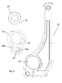
- the adjustable backrest support 10 includes a seat back or a backrest 12 connected to a seat back mount 14.
- the seat back mount 14 is connected to a backrest riser 16 such that the backrest 12 is adjustable in a number of different height positions.
- the backrest riser 16 is connected to a backrest reclining mount, shown generally at 18, that is supported on a wheelchair frame 20 by a backrest mounting bracket 19.
- the wheelchair frame 20 includes spaced apart side frame tubes (not shown).
- the backrest reclining mount 18 permits the recline angle of the backrest 12 to be adjusted relative to the wheelchair frame 20.
- the backrest reclining mount 18 permits movement of the backrest support 10 from an upright position (shown in solid lines) to a reclined position of the backrest support 10' (shown in dashed lines).
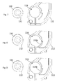
- the backrest reclining mount 18 includes a clamp 22 having a riser mount 24 and a strut clamp 26.
- the riser mount 24 is configured to retain the backrest riser 16 and support user applied loads from the backrest 12.
- the strut clamp 26 includes an aperture 28 having a circumferential profile 28a that is configured to mate with a strut 30 having a torque transmitting or torque resistive profile 32.
- the strut 30 further includes attachment ends 30a and 30b that attach to the backrest mounting bracket 19.
- the backrest mounting bracket 19 may connect to the wheelchair frame 20 in a number of lengthwise or longitudinal mounting positions that vary the depth of seating.
- the strut 30 and mounting bracket 19 may be configured as a cross member that connects two sides, such as left and right sides of frame 20 together. In this way, mounting and reclining movement of the backrest assembly 10 is independent of any back cane structures (not shown).
- the torque transmitting profile 32 may be any suitable shape that is capable of transmitting a torque load applied thereto.
- the circumferential profile 28a of the aperture 28 further includes a limiter slot 28b that cooperates with the strut 30 to permit assembly of the strut 30 through the aperture 28.
- the limiter slot 28b is sized to permit the torque transmitting profile 32 of the strut 30 to be rotated through a range of motion relative to the aperture 28. In certain embodiments, the limiter slot 28b may also act to limit the overall range of reclining motion of the backrest assembly 10.
- the clamp 22 includes a deflection slot 34 or "saw slot” that permits the circumference of the aperture 28 to close around and firmly grip the mating surface of the strut 30.
- the aperture 28 may be positioned, as shown, on both sides of the clamp 22 or may be a single aperture, either on one side or centrally located in the strut clamp 26.
- a pinch bolt hole 36 Associated with the aperture 28 is a pinch bolt hole 36.
- the pinch bolt hole 36 intersects the deflection slot 34 such that a pinch bolt 38 can draw the aperture 28 around the strut 30.
- a clamping barrel nut 40 is disposed in a hole 42, that also intersects the pinch bolt hole 36 and is configured to engage the pinch bolt 38 to permit clamping of the clamp 22 to the strut 30.
- a threaded end of the pinch bolt hole 36 or a conventional nut may be substituted for the clamping barrel nut 40.
- An adjuster ring shown generally at 44, includes a strut aperture 46 and an adjuster slot 48.
- the adjuster ring 44 is configured to be inserted into a ring slot 50, formed in the clamp 22 between the apertures 28, as shown in Figs. 3-5 .
- the ring slot 50 may be one or two ring slots positioned where the apertures 28 are illustrated in Fig. 2 .
- the adjuster ring 44 is inserted into the ring slot 50 such that the strut aperture 46 is generally in coaxial alignment with the apertures 28.
- the strut aperture 46 is shaped so as to permit the strut 30 to extend therethrough and generally conform to the outer shape of the strut 30 and the torque transmitting profile 32, as shown in the enlarged view of Fig. 6 .
- the adjuster slot 48 is illustrated as a pair of spaced-apart oblong holes 48a and 48b, as shown in Figs. 3-5 , that accept an angle adjuster 52. Alternatively, the adjuster slot 48 may be opened at the bottom, if desired.
- the angle adjuster 52 is a shown as a threaded bolt though other structures may be used, if so desired.
- the angle adjuster 52 passes through an adjustment aperture 54 in the strut clamp 26.
- the adjuster slot 48 includes an oblong nut aperture 56 that accepts an adjusting barrel nut 58 that threads onto the angle adjuster 52. As shown in Figs. 3-5 , the nut aperture 56 permits the adjusting barrel nut 58 to move toward or away (illustrated as clockwise or counterclockwise rotation) from the strut 30 as the angle adjuster 52 is rotated.
- the end of the angle adjuster 52 may be supported, relative to the clamp 22, by a cap 60 that may act as a bushing to locate the angle adjuster within the strut clamp 26 and also permit rotation of the angle adjuster 52.
- This movement is enabled by the strut 30 being fixed to the wheelchair frame 20 and the strut aperture 46 of the adjusting ring 44 having a complementary profile to that of the torque transmitting profile 32 of the strut 30.
- the angle adjuster 52 may push against the strut clamp surface 26 in one direction and the cap 60 pushing during rotation in the opposite direction. As shown in Fig. 4 , rotation of the angle adjuster 52 (counterclockwise for a right-hand threaded angle adjuster 52) rotates the clamp 22, and thus the backrest 12 to a forward tilted position. Rotating the angle adjuster 52 in the opposite direction moves the clamp 22 to the reclined position shown in Fig. 5 .
- the clamp 22 may be adjusted to any intermediate angular position and fixed relative to the strut 30 by way of the pinch bolts 38.
- Figs. 7-9 there are illustrated different examples of various embodiments of torque transmitting profiles and corresponding strut apertures. It should be understood that these examples are not exhaustive of the shapes that may be used in accordance with various embodiments of the invention. It should be further understood that a corresponding adjuster ring (not shown) will have a strut aperture having a mating profile with the torque transmitting profile of the strut, as described above in the previous embodiment.
- Fig. 7 illustrates a strut 130 having a keyway torque transmitting profile 132.
- a clamp 122 having a round aperture 128 may be provided without a limiter slot.
- Movement of the clamp 122 may be limited at either extremes of travel by an adjuster ring (not shown) locating against a ring slot (not shown) as illustrated in Figs. 3-5 .
- Fig. 8 illustrates a strut 230 having a cam torque transmitting profile 232 and a clamp 222 having an aperture 228 and a limiter slot 228b.
- Fig. 9 illustrates a strut 330 having a portion of a hexagonal torque transmitting profile 332 and a clamp 322 having an aperture 328 and a limiter slot 328b.
- the strut 30 shown in Fig. 1 to 5 can be sufficiently long to provide a lateral adjustment of the backrest 12 relative to the wheelchair frame 20.
- the adjustable backrest support 10 may be moved to a second lateral position of the support 10". This adjustment permits compensation for users having spine curvature issues or an inability to sit upright in the chair.
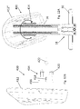
- the backrest 12 may be mounted to the seat back mount 14, where the seat back mount 14 includes a hinge connection 14a and an adjuster connection 14b to provide an angular adjustment of the backrest 12 relative to the backrest riser 16, for added comfort.
- the adjuster connection 14b is configured as a slotted locking arm extending from the backrest 12 that can be fixed in a plurality of inclination angles relative to a slide block 14c by way of a fastener, such as a bolt and nut, over-center clamp, or other locking arrangement.
- a fastener such as a bolt and nut, over-center clamp, or other locking arrangement.
- the slot may be formed in the slide block 14c, if so desired.
- the slide block 14c is configured to axially move along the backrest riser 16 to vary the height position of the backrest 12 relative to the frame 20.
- the inclination angle of the backrest 12 may be moved to a second position of the backrest 12'.
- an adjustable backrest support 400 may include a backrest 412 attached to a compound angle seatback mount 414.
- the compound angle seat back mount 414 includes a pivot mounting plate 416 that attaches to the backrest 412.
- the pivot mounting plate 416 includes a pivot stem 418 that attaches to a seatback angle adjusting bracket 420, similar to the seatback mount 14.
- An adjusting lever 422 permits the backrest 412 to be rotated to a desired angle substantially within a plane generally parallel to the backrest riser 16, to a position such as backrest position 412".
Landscapes
- Health & Medical Sciences (AREA)
- Life Sciences & Earth Sciences (AREA)
- Animal Behavior & Ethology (AREA)
- General Health & Medical Sciences (AREA)
- Public Health (AREA)
- Veterinary Medicine (AREA)
- Chairs For Special Purposes, Such As Reclining Chairs (AREA)
- Seats For Vehicles (AREA)
Applications Claiming Priority (1)
| Application Number | Priority Date | Filing Date | Title |
|---|---|---|---|
| US201461946737P | 2014-03-01 | 2014-03-01 |
Publications (3)
| Publication Number | Publication Date |
|---|---|
| EP2913038A2 true EP2913038A2 (fr) | 2015-09-02 |
| EP2913038A3 EP2913038A3 (fr) | 2015-12-02 |
| EP2913038B1 EP2913038B1 (fr) | 2017-05-10 |
Family
ID=52598622
Family Applications (1)
| Application Number | Title | Priority Date | Filing Date |
|---|---|---|---|
| EP15157234.4A Active EP2913038B1 (fr) | 2014-03-01 | 2015-03-02 | Dossier de chaise roulante présentant un réglage de position |
Country Status (2)
| Country | Link |
|---|---|
| US (1) | US20150245964A1 (fr) |
| EP (1) | EP2913038B1 (fr) |
Families Citing this family (3)
| Publication number | Priority date | Publication date | Assignee | Title |
|---|---|---|---|---|
| US10182953B2 (en) * | 2015-10-28 | 2019-01-22 | Sunrise Medical (Us), Llc | Wheelchair backrest mounting system |
| US10194745B2 (en) * | 2015-11-06 | 2019-02-05 | The Comfort Companies, Llc | Assembly for mounting and independent multi-direction adjustment of a seat back |
| CA3015850A1 (fr) | 2016-03-01 | 2017-09-08 | Motion Composites Inc | Cadre de fauteuil roulant |
Family Cites Families (9)
| Publication number | Priority date | Publication date | Assignee | Title |
|---|---|---|---|---|
| US5364162A (en) * | 1991-03-01 | 1994-11-15 | Roho, Inc. | Backrest assembly for a wheelchair |
| US6378947B1 (en) * | 1999-04-12 | 2002-04-30 | Bloorview Macmillan Centre | Seating system |
| US6749262B2 (en) * | 2000-02-28 | 2004-06-15 | Pride Mobility Products Corporation | Adjustable hinge and support structure |
| AU2002358213B2 (en) * | 2001-12-14 | 2007-07-12 | The Helping Hand Company (Ledbury) Limited | Improvements relating to torso support structures |
| EP1974707B1 (fr) * | 2007-03-08 | 2011-07-20 | Sunrise Medical HHG Inc. | Dossier d'un fauteuil roulant avec un matériel d'assemblage à deux points |
| CA2789675C (fr) * | 2010-02-11 | 2015-05-12 | Roho, Inc. | Ensemble de montage pour dossier de fauteuil roulant |
| EP2547548A4 (fr) * | 2010-03-16 | 2015-04-01 | Invacare Corp | Ensemble fauteuil roulant |
| US8517469B1 (en) * | 2012-09-06 | 2013-08-27 | Aspen Seating, Llc | Three-axis adjustable back support assembly and method |
| US8684398B1 (en) * | 2013-06-18 | 2014-04-01 | Michael Nyitray | Adjustable wheelchair seat |
-
2015
- 2015-03-02 US US14/635,173 patent/US20150245964A1/en not_active Abandoned
- 2015-03-02 EP EP15157234.4A patent/EP2913038B1/fr active Active
Non-Patent Citations (1)
| Title |
|---|
| None |
Also Published As
| Publication number | Publication date |
|---|---|
| US20150245964A1 (en) | 2015-09-03 |
| EP2913038A3 (fr) | 2015-12-02 |
| EP2913038B1 (fr) | 2017-05-10 |
Similar Documents
| Publication | Publication Date | Title |
|---|---|---|
| US10182953B2 (en) | Wheelchair backrest mounting system | |
| US11510494B2 (en) | Adjustable head support | |
| US6322145B1 (en) | Wheelchair seat back with adjustable tilt | |
| CA2636994C (fr) | Fauteuil inclinable a assise fixe et mecanisme de leviers en ligne | |
| US7980580B2 (en) | Clamping assembly | |
| EP2913038B1 (fr) | Dossier de chaise roulante présentant un réglage de position | |
| WO2001064157A3 (fr) | Ensemble support lombaire a reglage multiples destine a un fauteuil roulant | |
| AU2011216161B2 (en) | Wheelchair back mounting assembly | |
| US10595635B2 (en) | Assembly for mounting and independent multi-direction adjustment of a seat back | |
| EP1765634B1 (fr) | Mecanisme d' accoudoir rotatif | |
| US20090283983A1 (en) | Wheelchair construction | |
| US7427078B1 (en) | Wheelchair swing away system | |
| TWM481655U (zh) | 扶手裝置 | |
| US7661761B1 (en) | Motorcycle backrest assembly | |
| EP2709491B1 (fr) | Appareil de support latéral pour une chaise | |
| EP0325569B1 (fr) | Dispositif pour sièges réglables | |
| US11641944B2 (en) | Double angle back support adjustment | |
| AU2012259529A1 (en) | Lateral support apparatus for a chair | |
| AU2003213829A1 (en) | Adjustable seating system | |
| US20060076814A1 (en) | Adjustable backrest on personal mobility aid | |
| AU2019100879A4 (en) | Chair seat sliding and locking mechanism | |
| EP3785570B1 (fr) | Assise de chaise avec mécanisme de coulissement et de verrouillage | |
| CA3060300C (fr) | Siege de fauteuil et mecanisme de verrouillage | |
| US10820702B1 (en) | Chair seat sliding and locking mechanism | |
| GB2447282A (en) | Detachable headrest for a wheelchair |
Legal Events
| Date | Code | Title | Description |
|---|---|---|---|
| PUAI | Public reference made under article 153(3) epc to a published international application that has entered the european phase |
Free format text: ORIGINAL CODE: 0009012 |
|
| AK | Designated contracting states |
Kind code of ref document: A2 Designated state(s): AL AT BE BG CH CY CZ DE DK EE ES FI FR GB GR HR HU IE IS IT LI LT LU LV MC MK MT NL NO PL PT RO RS SE SI SK SM TR |
|
| AX | Request for extension of the european patent |
Extension state: BA ME |
|
| PUAL | Search report despatched |
Free format text: ORIGINAL CODE: 0009013 |
|
| AK | Designated contracting states |
Kind code of ref document: A3 Designated state(s): AL AT BE BG CH CY CZ DE DK EE ES FI FR GB GR HR HU IE IS IT LI LT LU LV MC MK MT NL NO PL PT RO RS SE SI SK SM TR |
|
| AX | Request for extension of the european patent |
Extension state: BA ME |
|
| RIC1 | Information provided on ipc code assigned before grant |
Ipc: A61G 5/10 20060101AFI20151028BHEP Ipc: A61G 5/12 20060101ALN20151028BHEP |
|
| 17P | Request for examination filed |
Effective date: 20160120 |
|
| RBV | Designated contracting states (corrected) |
Designated state(s): AL AT BE BG CH CY CZ DE DK EE ES FI FR GB GR HR HU IE IS IT LI LT LU LV MC MK MT NL NO PL PT RO RS SE SI SK SM TR |
|
| RIC1 | Information provided on ipc code assigned before grant |
Ipc: A61G 5/10 20060101AFI20160714BHEP Ipc: A61G 5/12 20060101ALN20160714BHEP |
|
| GRAP | Despatch of communication of intention to grant a patent |
Free format text: ORIGINAL CODE: EPIDOSNIGR1 |
|
| INTG | Intention to grant announced |
Effective date: 20160929 |
|
| RIC1 | Information provided on ipc code assigned before grant |
Ipc: A61G 5/10 20060101AFI20160920BHEP Ipc: A61G 5/12 20060101ALN20160920BHEP |
|
| GRAS | Grant fee paid |
Free format text: ORIGINAL CODE: EPIDOSNIGR3 |
|
| GRAA | (expected) grant |
Free format text: ORIGINAL CODE: 0009210 |
|
| RAP1 | Party data changed (applicant data changed or rights of an application transferred) |
Owner name: SUNRISE MEDICAL GMBH |
|
| AK | Designated contracting states |
Kind code of ref document: B1 Designated state(s): AL AT BE BG CH CY CZ DE DK EE ES FI FR GB GR HR HU IE IS IT LI LT LU LV MC MK MT NL NO PL PT RO RS SE SI SK SM TR |
|
| REG | Reference to a national code |
Ref country code: GB Ref legal event code: FG4D |
|
| REG | Reference to a national code |
Ref country code: AT Ref legal event code: REF Ref document number: 891542 Country of ref document: AT Kind code of ref document: T Effective date: 20170515 Ref country code: CH Ref legal event code: EP |
|
| REG | Reference to a national code |
Ref country code: IE Ref legal event code: FG4D |
|
| REG | Reference to a national code |
Ref country code: DE Ref legal event code: R096 Ref document number: 602015002572 Country of ref document: DE |
|
| REG | Reference to a national code |
Ref country code: NL Ref legal event code: FP |
|
| REG | Reference to a national code |
Ref country code: SE Ref legal event code: TRGR |
|
| REG | Reference to a national code |
Ref country code: LT Ref legal event code: MG4D Ref country code: NO Ref legal event code: T2 Effective date: 20170510 |
|
| REG | Reference to a national code |
Ref country code: AT Ref legal event code: MK05 Ref document number: 891542 Country of ref document: AT Kind code of ref document: T Effective date: 20170510 |
|
| PG25 | Lapsed in a contracting state [announced via postgrant information from national office to epo] |
Ref country code: FI Free format text: LAPSE BECAUSE OF FAILURE TO SUBMIT A TRANSLATION OF THE DESCRIPTION OR TO PAY THE FEE WITHIN THE PRESCRIBED TIME-LIMIT Effective date: 20170510 Ref country code: GR Free format text: LAPSE BECAUSE OF FAILURE TO SUBMIT A TRANSLATION OF THE DESCRIPTION OR TO PAY THE FEE WITHIN THE PRESCRIBED TIME-LIMIT Effective date: 20170811 Ref country code: LT Free format text: LAPSE BECAUSE OF FAILURE TO SUBMIT A TRANSLATION OF THE DESCRIPTION OR TO PAY THE FEE WITHIN THE PRESCRIBED TIME-LIMIT Effective date: 20170510 Ref country code: HR Free format text: LAPSE BECAUSE OF FAILURE TO SUBMIT A TRANSLATION OF THE DESCRIPTION OR TO PAY THE FEE WITHIN THE PRESCRIBED TIME-LIMIT Effective date: 20170510 Ref country code: ES Free format text: LAPSE BECAUSE OF FAILURE TO SUBMIT A TRANSLATION OF THE DESCRIPTION OR TO PAY THE FEE WITHIN THE PRESCRIBED TIME-LIMIT Effective date: 20170510 Ref country code: AT Free format text: LAPSE BECAUSE OF FAILURE TO SUBMIT A TRANSLATION OF THE DESCRIPTION OR TO PAY THE FEE WITHIN THE PRESCRIBED TIME-LIMIT Effective date: 20170510 |
|
| PG25 | Lapsed in a contracting state [announced via postgrant information from national office to epo] |
Ref country code: BG Free format text: LAPSE BECAUSE OF FAILURE TO SUBMIT A TRANSLATION OF THE DESCRIPTION OR TO PAY THE FEE WITHIN THE PRESCRIBED TIME-LIMIT Effective date: 20170810 Ref country code: LV Free format text: LAPSE BECAUSE OF FAILURE TO SUBMIT A TRANSLATION OF THE DESCRIPTION OR TO PAY THE FEE WITHIN THE PRESCRIBED TIME-LIMIT Effective date: 20170510 Ref country code: RS Free format text: LAPSE BECAUSE OF FAILURE TO SUBMIT A TRANSLATION OF THE DESCRIPTION OR TO PAY THE FEE WITHIN THE PRESCRIBED TIME-LIMIT Effective date: 20170510 Ref country code: PL Free format text: LAPSE BECAUSE OF FAILURE TO SUBMIT A TRANSLATION OF THE DESCRIPTION OR TO PAY THE FEE WITHIN THE PRESCRIBED TIME-LIMIT Effective date: 20170510 Ref country code: IS Free format text: LAPSE BECAUSE OF FAILURE TO SUBMIT A TRANSLATION OF THE DESCRIPTION OR TO PAY THE FEE WITHIN THE PRESCRIBED TIME-LIMIT Effective date: 20170910 |
|
| PG25 | Lapsed in a contracting state [announced via postgrant information from national office to epo] |
Ref country code: DK Free format text: LAPSE BECAUSE OF FAILURE TO SUBMIT A TRANSLATION OF THE DESCRIPTION OR TO PAY THE FEE WITHIN THE PRESCRIBED TIME-LIMIT Effective date: 20170510 Ref country code: RO Free format text: LAPSE BECAUSE OF FAILURE TO SUBMIT A TRANSLATION OF THE DESCRIPTION OR TO PAY THE FEE WITHIN THE PRESCRIBED TIME-LIMIT Effective date: 20170510 Ref country code: EE Free format text: LAPSE BECAUSE OF FAILURE TO SUBMIT A TRANSLATION OF THE DESCRIPTION OR TO PAY THE FEE WITHIN THE PRESCRIBED TIME-LIMIT Effective date: 20170510 Ref country code: SK Free format text: LAPSE BECAUSE OF FAILURE TO SUBMIT A TRANSLATION OF THE DESCRIPTION OR TO PAY THE FEE WITHIN THE PRESCRIBED TIME-LIMIT Effective date: 20170510 Ref country code: CZ Free format text: LAPSE BECAUSE OF FAILURE TO SUBMIT A TRANSLATION OF THE DESCRIPTION OR TO PAY THE FEE WITHIN THE PRESCRIBED TIME-LIMIT Effective date: 20170510 |
|
| REG | Reference to a national code |
Ref country code: DE Ref legal event code: R097 Ref document number: 602015002572 Country of ref document: DE |
|
| PG25 | Lapsed in a contracting state [announced via postgrant information from national office to epo] |
Ref country code: SM Free format text: LAPSE BECAUSE OF FAILURE TO SUBMIT A TRANSLATION OF THE DESCRIPTION OR TO PAY THE FEE WITHIN THE PRESCRIBED TIME-LIMIT Effective date: 20170510 |
|
| PLBE | No opposition filed within time limit |
Free format text: ORIGINAL CODE: 0009261 |
|
| STAA | Information on the status of an ep patent application or granted ep patent |
Free format text: STATUS: NO OPPOSITION FILED WITHIN TIME LIMIT |
|
| REG | Reference to a national code |
Ref country code: FR Ref legal event code: PLFP Year of fee payment: 4 |
|
| 26N | No opposition filed |
Effective date: 20180213 |
|
| PG25 | Lapsed in a contracting state [announced via postgrant information from national office to epo] |
Ref country code: SI Free format text: LAPSE BECAUSE OF FAILURE TO SUBMIT A TRANSLATION OF THE DESCRIPTION OR TO PAY THE FEE WITHIN THE PRESCRIBED TIME-LIMIT Effective date: 20170510 |
|
| REG | Reference to a national code |
Ref country code: CH Ref legal event code: PL |
|
| PG25 | Lapsed in a contracting state [announced via postgrant information from national office to epo] |
Ref country code: MC Free format text: LAPSE BECAUSE OF FAILURE TO SUBMIT A TRANSLATION OF THE DESCRIPTION OR TO PAY THE FEE WITHIN THE PRESCRIBED TIME-LIMIT Effective date: 20170510 |
|
| REG | Reference to a national code |
Ref country code: BE Ref legal event code: MM Effective date: 20180331 |
|
| REG | Reference to a national code |
Ref country code: IE Ref legal event code: MM4A |
|
| PG25 | Lapsed in a contracting state [announced via postgrant information from national office to epo] |
Ref country code: LU Free format text: LAPSE BECAUSE OF NON-PAYMENT OF DUE FEES Effective date: 20180302 |
|
| PG25 | Lapsed in a contracting state [announced via postgrant information from national office to epo] |
Ref country code: IE Free format text: LAPSE BECAUSE OF NON-PAYMENT OF DUE FEES Effective date: 20180302 |
|
| PG25 | Lapsed in a contracting state [announced via postgrant information from national office to epo] |
Ref country code: LI Free format text: LAPSE BECAUSE OF NON-PAYMENT OF DUE FEES Effective date: 20180331 Ref country code: CH Free format text: LAPSE BECAUSE OF NON-PAYMENT OF DUE FEES Effective date: 20180331 Ref country code: BE Free format text: LAPSE BECAUSE OF NON-PAYMENT OF DUE FEES Effective date: 20180331 |
|
| PG25 | Lapsed in a contracting state [announced via postgrant information from national office to epo] |
Ref country code: MT Free format text: LAPSE BECAUSE OF NON-PAYMENT OF DUE FEES Effective date: 20180302 |
|
| PG25 | Lapsed in a contracting state [announced via postgrant information from national office to epo] |
Ref country code: TR Free format text: LAPSE BECAUSE OF FAILURE TO SUBMIT A TRANSLATION OF THE DESCRIPTION OR TO PAY THE FEE WITHIN THE PRESCRIBED TIME-LIMIT Effective date: 20170510 |
|
| PG25 | Lapsed in a contracting state [announced via postgrant information from national office to epo] |
Ref country code: PT Free format text: LAPSE BECAUSE OF FAILURE TO SUBMIT A TRANSLATION OF THE DESCRIPTION OR TO PAY THE FEE WITHIN THE PRESCRIBED TIME-LIMIT Effective date: 20170510 |
|
| PG25 | Lapsed in a contracting state [announced via postgrant information from national office to epo] |
Ref country code: MK Free format text: LAPSE BECAUSE OF NON-PAYMENT OF DUE FEES Effective date: 20170510 Ref country code: HU Free format text: LAPSE BECAUSE OF FAILURE TO SUBMIT A TRANSLATION OF THE DESCRIPTION OR TO PAY THE FEE WITHIN THE PRESCRIBED TIME-LIMIT; INVALID AB INITIO Effective date: 20150302 Ref country code: CY Free format text: LAPSE BECAUSE OF FAILURE TO SUBMIT A TRANSLATION OF THE DESCRIPTION OR TO PAY THE FEE WITHIN THE PRESCRIBED TIME-LIMIT Effective date: 20170510 |
|
| PG25 | Lapsed in a contracting state [announced via postgrant information from national office to epo] |
Ref country code: AL Free format text: LAPSE BECAUSE OF FAILURE TO SUBMIT A TRANSLATION OF THE DESCRIPTION OR TO PAY THE FEE WITHIN THE PRESCRIBED TIME-LIMIT Effective date: 20170510 |
|
| PGFP | Annual fee paid to national office [announced via postgrant information from national office to epo] |
Ref country code: NO Payment date: 20230321 Year of fee payment: 9 Ref country code: FR Payment date: 20230320 Year of fee payment: 9 |
|
| PGFP | Annual fee paid to national office [announced via postgrant information from national office to epo] |
Ref country code: SE Payment date: 20230315 Year of fee payment: 9 |
|
| P01 | Opt-out of the competence of the unified patent court (upc) registered |
Effective date: 20230619 |
|
| PGFP | Annual fee paid to national office [announced via postgrant information from national office to epo] |
Ref country code: IT Payment date: 20230331 Year of fee payment: 9 |
|
| PGFP | Annual fee paid to national office [announced via postgrant information from national office to epo] |
Ref country code: NL Payment date: 20240320 Year of fee payment: 10 |
|
| PGFP | Annual fee paid to national office [announced via postgrant information from national office to epo] |
Ref country code: DE Payment date: 20240321 Year of fee payment: 10 Ref country code: GB Payment date: 20240322 Year of fee payment: 10 |