US8517469B1 - Three-axis adjustable back support assembly and method - Google Patents
Three-axis adjustable back support assembly and method Download PDFInfo
- Publication number
- US8517469B1 US8517469B1 US13/605,638 US201213605638A US8517469B1 US 8517469 B1 US8517469 B1 US 8517469B1 US 201213605638 A US201213605638 A US 201213605638A US 8517469 B1 US8517469 B1 US 8517469B1
- Authority
- US
- United States
- Prior art keywords
- adjustment
- arms
- extension
- relative
- arm
- Prior art date
- Legal status (The legal status is an assumption and is not a legal conclusion. Google has not performed a legal analysis and makes no representation as to the accuracy of the status listed.)
- Active
Links
- 238000000034 method Methods 0.000 title claims description 19
- 230000000717 retained effect Effects 0.000 claims abstract description 7
- 230000013011 mating Effects 0.000 claims description 32
- 230000000295 complement effect Effects 0.000 claims description 31
- 230000014759 maintenance of location Effects 0.000 claims description 21
- 238000000926 separation method Methods 0.000 claims description 16
- 239000007787 solid Substances 0.000 description 13
- 230000006872 improvement Effects 0.000 description 8
- 230000002411 adverse Effects 0.000 description 4
- 230000001144 postural effect Effects 0.000 description 4
- 230000006835 compression Effects 0.000 description 3
- 238000007906 compression Methods 0.000 description 3
- 230000035479 physiological effects, processes and functions Effects 0.000 description 3
- 208000027205 Congenital disease Diseases 0.000 description 2
- 208000029767 Congenital, Hereditary, and Neonatal Diseases and Abnormalities Diseases 0.000 description 2
- 230000008901 benefit Effects 0.000 description 2
- 230000006735 deficit Effects 0.000 description 2
- 230000006866 deterioration Effects 0.000 description 2
- 201000010099 disease Diseases 0.000 description 2
- 208000037265 diseases, disorders, signs and symptoms Diseases 0.000 description 2
- 230000036541 health Effects 0.000 description 2
- 208000014674 injury Diseases 0.000 description 2
- 230000008736 traumatic injury Effects 0.000 description 2
- 208000004210 Pressure Ulcer Diseases 0.000 description 1
- 230000002730 additional effect Effects 0.000 description 1
- 238000010276 construction Methods 0.000 description 1
- 230000007423 decrease Effects 0.000 description 1
- 230000003467 diminishing effect Effects 0.000 description 1
- 230000000694 effects Effects 0.000 description 1
- 230000005484 gravity Effects 0.000 description 1
- 238000003780 insertion Methods 0.000 description 1
- 230000037431 insertion Effects 0.000 description 1
- 238000009434 installation Methods 0.000 description 1
- 230000003993 interaction Effects 0.000 description 1
- 230000007246 mechanism Effects 0.000 description 1
- 230000000284 resting effect Effects 0.000 description 1
- 238000006467 substitution reaction Methods 0.000 description 1
- 230000002618 waking effect Effects 0.000 description 1
- 238000003466 welding Methods 0.000 description 1
Images


Classifications
-
- A—HUMAN NECESSITIES
- A61—MEDICAL OR VETERINARY SCIENCE; HYGIENE
- A61G—TRANSPORT, PERSONAL CONVEYANCES, OR ACCOMMODATION SPECIALLY ADAPTED FOR PATIENTS OR DISABLED PERSONS; OPERATING TABLES OR CHAIRS; CHAIRS FOR DENTISTRY; FUNERAL DEVICES
- A61G5/00—Chairs or personal conveyances specially adapted for patients or disabled persons, e.g. wheelchairs
- A61G5/10—Parts, details or accessories
- A61G5/12—Rests specially adapted therefor, e.g. for the head or the feet
-
- A—HUMAN NECESSITIES
- A61—MEDICAL OR VETERINARY SCIENCE; HYGIENE
- A61G—TRANSPORT, PERSONAL CONVEYANCES, OR ACCOMMODATION SPECIALLY ADAPTED FOR PATIENTS OR DISABLED PERSONS; OPERATING TABLES OR CHAIRS; CHAIRS FOR DENTISTRY; FUNERAL DEVICES
- A61G5/00—Chairs or personal conveyances specially adapted for patients or disabled persons, e.g. wheelchairs
- A61G5/10—Parts, details or accessories
- A61G5/1056—Arrangements for adjusting the seat
- A61G5/1067—Arrangements for adjusting the seat adjusting the backrest relative to the seat portion
-
- A—HUMAN NECESSITIES
- A61—MEDICAL OR VETERINARY SCIENCE; HYGIENE
- A61G—TRANSPORT, PERSONAL CONVEYANCES, OR ACCOMMODATION SPECIALLY ADAPTED FOR PATIENTS OR DISABLED PERSONS; OPERATING TABLES OR CHAIRS; CHAIRS FOR DENTISTRY; FUNERAL DEVICES
- A61G5/00—Chairs or personal conveyances specially adapted for patients or disabled persons, e.g. wheelchairs
- A61G5/10—Parts, details or accessories
- A61G5/12—Rests specially adapted therefor, e.g. for the head or the feet
- A61G5/122—Rests specially adapted therefor, e.g. for the head or the feet for the back
Definitions
- This invention relates to seating and support devices for effectively supporting a person in a wheelchair. More particularly, the present invention relates to a new and improved adjustable back support assembly and method which allows a physical therapist or a wheelchair seating professional to establish the most effective and safe position for supporting the back and upper torso of an individual seated in a wheelchair, along and about three mutually perpendicular axes, in an efficient and effective manner.
- wheelchair users who have physical disabilities and associated posture and postural control impairments, such as those typically caused by congenital disorders, to achieve an optimal seating and support position on the wheelchair. It is equally important to do the same for wheelchair users who have a more typical size and shape but have been disabled by acquired or traumatic injuries or debilitating disease. These individuals spend most of their waking hours residing in a wheelchair. Obtaining individualized support and alignment of the wheelchair user is important for optimal mobility, function, health and safety. Without achieving the proper and safe posture, the wheelchair user may be susceptible to further deterioration in physical capabilities, due to progression of postural deformity and associated deterioration of health and mobility as well as increased risk for pressure ulcers induced from sitting.
- the seat cushion and the back cushion In an individualized manner according to the posture and physiology of the wheelchair user.
- the seat cushion In the case of the seat cushion, much of the support arises from the contour of the cushion.
- Positioning the back cushion is usually considerably more complex, because more adjustments are required.
- the back and upper torso of the wheelchair user must usually be positioned relative to the seat cushion, to achieve balance on the wheelchair so the user does not experience a tendency to fall or lean forward, backward or sideways.
- the physiology of the back and upper torso of the wheelchair user is complex in shape, requiring more support than with a more typical physiology.
- back support devices have been developed which provide longitudinal and pivotal movement in one or all of the three mutually perpendicular axes. Those back support devices which provide longitudinal and pivotal movement in all three mutually perpendicular axes are usually the most desirable for use.
- the prior three-axis longitudinal and pivotal movement back support devices are very complex in construction, with many moving parts having complex interdependent relationships and positions, which a physical therapist or wheelchair seating professional may not fully appreciate or fully utilize when fitting the back support device to the wheelchair user.
- adjustments can be achieved only with great difficulty and effort, due to the mechanical complexity of the device.
- the positioning on or about one axis is so interdependent with the positioning on or about one or both of the other two axes that an adjustment along or about one axis creates the undesirable effect of changing the position on or about one or more of the other two axes, making it extremely difficult and time-consuming for the fitting therapist or seating professional to achieve optimal support and positioning.
- the complexity of the device complicates the effort, since many physical therapists and wheelchair seating professionals have difficulty understanding the mechanical relationships involved in adjusting the numerous elements. Adjustments are also complicated by the necessity to insert separate shims and adjustment elements into the mechanical structure, and the necessity to disassemble parts to make adjustments. Losing or misplacing parts is constant risk, and the back support device cannot be used until replacement parts are obtained.
- prior mechanical back support devices also frequently leads to loss of the optimal position, because the nature of the mechanical devices make them susceptible to slip from the initial adjusted position.
- the mechanical features of prior back support devices also cause them to feel or to be perceived as loose in assembly or connection to the wheelchair. Such a feeling is extremely disconcerting to the security of a wheelchair user, since the user usually depends on the mechanical integrity of the support device when controlling the wheelchair and to prevent falls from the wheelchair.
- Many prior back support devices are also heavy, which adds to the effort of maneuvering the wheelchair.
- Many prior back support devices are not aesthetically pleasing in appearance, which also detracts from the persona or self-image of the wheelchair user.
- This invention is for an apparatus and method which permits longitudinal and pivotal adjustment of a back support for the back and upper torso of a wheelchair user along and about the three mutually perpendicular axes.
- the longitudinal and pivotal adjustment along and about each of the three mutually perpendicular axes is accomplished independently of the adjustment about the other two mutually perpendicular axes.
- the back support apparatus allows movement along and about all three mutually perpendicular axes simultaneously to obtain an initial adjustment position. Once the initial adjustment position is established, individual fine adjustment in each of the six realms of movement is achieved without disturbing or otherwise adversely influencing the individual adjustments in the other five realms of movement.
- the components of the back support apparatus are rigidly and tightly coupled together, creating a strong, light-weight and aesthetically-pleasing structure that imparts a feeling of security and enhanced persona or self-image in the wheelchair user.
- the components of the back support apparatus connect together in a way which makes it extremely unlikely that the apparatus will lose its adjustment from use.
- the components of the back support apparatus are minimal in their number and straightforward in their interaction with one another, which makes the apparatus easier to understand, set up, adjust and use, all of which facilitates achieving optimal back support for the wheelchair user.
- the back support assembly comprises a pair of mounting devices adapted for connection to the wheelchair.
- a pair of adjustment arms each have first and second opposite ends. The first ends of the adjustment arms pivotally connect respectively to the mounting devices.
- a pair of extension arms each have first and second opposite ends. The first ends of the extension arms are connected respectively to the second ends of the adjustment arms to selectively pivot the extension arms relative to the adjustment arms and to rigidly maintain a selected pivotal position of each extension arm relative to the connected adjustment arm.
- the second end of each extension arm has a predetermined cross-sectional configuration.
- a connecting structure has opposite ends with openings into which the second ends of the extension arms are respectively inserted to telescope relative to the connecting structure.
- Each opening in the connecting structure has a complementary predetermined cross-sectional configuration corresponding to the predetermined cross-sectional configuration of the second ends of each extension arm which are inserted into that opening.
- a back retaining clamp is connected to the connecting structure to pivot or rotate selectively about the connecting structure.
- a back shell connector is connected to the back retaining clamp to move selectively vertically relative to the connecting structure.
- the back shell connector is adapted to connect to the back shell in a selected relative rotational position relative to the connecting structure.
- the method involves operatively and pivotally connecting first ends of two elongated adjustment arms to wheelchair back canes on respectively opposite transverse sides of the wheelchair frame, pivotally connecting first ends of elongated extension arms to second ends of the adjustment arms, telescopically extending second ends of the extension arms into opposite ends of a connecting structure, and operatively attaching the back shell to the connecting structure.
- the longitudinal position of the back cushion is adjusted along the longitudinal axis and the pivotal position of the back cushion is adjusted about the vertical axis by selectively establishing and fixing pivoted positions of the adjustment and extension arms relative to one another.
- the transverse position of the back cushion along the transverse axis is adjusted by either telescopically moving the connecting structure relative to the second ends of the extension arms and by positioning the back shell at a selected transverse position along the connecting structure.
- the pivoted position of the back cushion about the transverse axis is adjusted by selectively pivoting the back shell about the transverse axis relative to the connecting structure at the operative attachment of the back shell to the connecting structure.
- the vertical position of the back cushion is adjusted along the vertical axis by selectively positioning the back shell at a selected position along the vertical axis relative to the connecting structure at the operative attachment of the back shell to the connecting structure.
- the pivoted position of the back cushion about the longitudinal axis is adjusted by selectively pivoting the position the back shell about the longitudinal axis at the operative attachment of the back shell to the connecting structure. All of these adjustments are performed while the first ends of the adjustment arms remain operatively pivotally connected to the canes and while the second ends of the extension arms remain inserted in the connecting structure.
- FIG. 1 is a rear perspective view of a wheelchair with an attached three-axis adjustable back support assembly which incorporates the present invention.
- FIG. 2 is a front perspective view of the wheelchair shown in FIG. 1 .
- FIG. 3 is a side elevation view of the wheelchair shown in FIGS. 1 and 2 , upon which a wheelchair user is seated.
- FIG. 4 is an perspective view of the back support assembly shown in FIG. 1 with portions illustrated from different perspectives shown by a broken line.
- FIG. 5 is a perspective view of the back support assembly shown in FIG. 4 , with the some of the components shown in an exploded relationship.
- FIG. 6 is a horizontal cross sectional view of a clamp of a mounting device of the back support assembly shown in FIGS. 4 and 5 .
- FIG. 7A is a perspective view of a receiver block of the mounting device of the back support assembly shown in FIGS. 4 and 5 , illustrated connected in an alternative manner to a non-circular cane of a wheelchair by an attachment bracket.
- FIG. 7B is an exploded perspective view of a receiver block of the mounting device of the back support assembly shown in FIGS. 4 and 5 , illustrated connected in another alternative manner to a solid back of another type of wheelchair.
- FIG. 8 is a vertical cross-sectional view of an adjustment arm of the back support assembly shown in FIGS. 4 and 5 , shown positioned in a receiver block of the back support assembly shown in FIGS. 4 , 5 and 7 .
- FIG. 9 is the vertical cross-sectional view of FIG. 8 with an attached release lever pin of the back support assembly shown in FIGS. 4 and 5 .
- FIG. 10 is the vertical cross-sectional view of FIG. 8 with an attached solid connection pin of the back support assembly shown in FIGS. 4 and 5 , used as an alternative to and in substitution for the release lever pin shown in FIGS. 4 , 5 and 9 .
- FIG. 11 is an exploded perspective view of an adjustment arm and an extension arm of the back support assembly shown in FIGS. 4 and 5 , with different perspectives of the adjustment arm and the extension arm illustrated by a broken line.
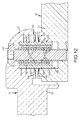
- FIG. 12 is a partial vertical cross-sectional view of the assembled relationship of the adjustment arm and the extension arm shown in FIG. 11 , illustrating disengagement during adjustment of the back support assembly.
- FIG. 13 is a transverse cross-sectional view of an extension arm of the back support assembly shown in FIGS. 4 , 5 , 11 and 12 , inserted within a connecting tube of the back support assembly.
- FIG. 14 is a perspective view of the connecting tube shown in FIG. 13 , a portion of the extension arms shown in FIGS. 11 and 12 , and a back retaining clamp shown in FIGS. 4 and 5 connected to the connecting tube, viewed from a perspective below the connecting tube to illustrate slots formed in the connecting tube and set screws in the slots connected to the extension arms.
- FIG. 15 is a partially-sectioned side elevation view of the back retaining clamp connected to the connecting tube shown in FIG. 14 .
- FIG. 16 is a top plan view of the back retaining clamp, shown partially sectioned in the plane of line 16 - 16 in FIG. 15 , with a back shell connector of the back support assembly shown in FIGS. 4 and 5 connected to the back retaining clamp.
- FIG. 17 is a perspective view of the back retaining clamp and the back shell connector shown in FIG. 16 , in assembled relationship and connected to the connecting tube of the back support assembly.
- FIGS. 18A , 18 B, 18 C and 18 D are generalized top plan views illustrating the range of longitudinal adjustment of the back support assembly shown in FIGS. 4 and 5 , along the longitudinal axis shown in FIG. 2 .
- FIGS. 19A and 19B are rear elevation views of the back retaining clamp shown in FIG. 17 , illustrating a range of pivotal adjustment of the back shell by the back support assembly shown in FIGS. 4 and 5 , about the longitudinal axis shown in FIG. 2 .
- FIGS. 20A , 20 B and 20 C are generalized top plan views illustrating the range of transverse adjustment of the back support assembly shown in FIGS. 4 and 5 , along the transverse axis shown in FIG. 2 .
- FIGS. 21A and 21B are generalized side elevation of views illustrating the range of pivoting adjustment of the back support assembly shown in FIGS. 4 and 5 , about the transverse axis shown in FIG. 2 .
- FIGS. 22A and 22B are generalized side elevation of views illustrating the range of vertical adjustment of the back support assembly shown in FIGS. 4 and 5 , along the vertical axis shown in FIG. 2 .
- FIGS. 23A and 23B are generalized top plan views illustrating the range of pivoting adjustment of the back support assembly shown in FIGS. 4 and 5 , about the vertical axis shown in FIG. 2 .
- FIGS. 1-3 A three-axis adjustable back support assembly 30 which embodies the present invention is shown generally in FIGS. 1-3 .
- the back support assembly 30 is attached between upright posts or canes 32 on opposite transverse sides of a tubular frame 34 of a conventional wheelchair 36 .
- the back support assembly 30 connects to and supports a back shell 38 to which a back cushion 40 is attached.
- the back shell 38 and the back cushion 40 are positioned relative to a seat cushion 42 which is supported on a platform 44 of the wheelchair frame 34 .
- the position of the back shell 38 and back cushion 40 relative to the seat cushion 42 supports and locates the back and upper torso of a wheelchair user 46 ( FIG. 3 ) seated on the wheelchair 36 , to enable the user 46 ( FIG.
- Proper and safe posture on the wheelchair 36 is particularly important to a wheelchair user who has physical disabilities and associated posture and postural control impairments, such as those typically caused by congenital disorders, as well as wheelchair users who have a more typical size and shape but have been disabled by acquired or traumatic injuries or disease.
- the three-axis back support assembly 30 positions and adjusts the back shell 38 and the back cushion 40 in a forward and backward manner ( FIGS. 18A-18D ) along a horizontal longitudinal axis 48 ( FIG. 2 ), as well as pivots the shell 38 and cushion 40 about that axis 48 ( FIGS. 19A and 19B ).
- the back support assembly 30 also adjusts the shell 38 and cushion 40 in a side to side manner ( FIGS. 20A-20C ) along a horizontal transverse axis 50 ( FIG. 2 ), and pivots the shell 38 and cushion 40 about that axis 50 ( FIGS. 21A and 21B ).
- the shell 38 and cushion 40 are also adjustable upward and downward ( FIGS. 22A and 22B ) along a vertical axis 52 ( FIG. 2 ), and is also adjustable to pivot about that vertical axis 52 ( FIGS. 23A and 23B ), by the back support assembly 30 .
- the conventional wheelchair 36 with which the back support assembly 30 is used typically has two drive wheels 54 which are attached on opposite sides of the wheelchair frame 34 by which the user 46 can maneuver the wheelchair 36 .
- Foot rests 56 extend downward from the frame 34 below the forward edge of the seat cushion 42 to support the feet of the user 46 .
- Casters 58 extend from the wheelchair frame 34 in front of the drive wheels 54 to provide the stability of a four-wheeled vehicle.
- many conventional wheelchair frames 34 are collapsible in a transverse direction, to facilitate storage and transportation.
- the back support assembly 30 is disconnectable from the canes 32 of the wheelchair frame 34 to separate the back shell 38 and back cushion 40 from the frame 34 , thereby allowing the wheelchair 36 to be collapsed.
- Adjustment arms 62 are attached at their first outer ends 64 to each mounting device 60 by a release lever pin 66 ( FIG. 9 ), or alternatively by a solid pin 68 ( FIG. 10 ).
- An opposite second inner end 70 of each adjustment arm 62 pivotally connects to a first outer end 72 of an extension arm 74 .
- the angle of the adjustment arm 62 and the extension arm 74 is fixed in a selectively adjustable manner to prevent the arms 62 and 74 from pivoting relative to one another.
- each extension arm 74 has an overall cross-sectional configuration of a parallel-segmented circle, formed by two flat, parallel extending segments 78 and 80 located diametrically opposite from one another.
- the two inner ends 76 of the two extension arms 74 each extend into opposite ends of a center connecting structure or hollow tube 82 .
- a center opening 84 of the connecting tube 82 has a cross-sectional configuration of the same or complementary shape as the inner portions 76 of the extension arms 74 ( FIG. 13 ), thereby preventing the connecting tube 82 from rotating relative to the extension arms 74 .
- a back retaining clamp 86 is firmly attached to the connecting tube 82 to prevent rotation relative to the connecting tube 82 .
- a back shell connector 88 is adjustably connected to the back shell 38 .
- the back shell connector 88 and the back retaining clamp 86 are interconnected by a T-shaped bar portion 90 of the back retaining clamp 86 which extends into and moves along a C-shaped channel 92 of back shell retaining assembly 88 ( FIG. 16 ).
- the C-shaped channel 92 is rigidly attached to a circular plate 94
- the back shell 38 is rigidly connected to the plate 94 at selectively adjustable pivoted positions ( FIGS. 19A and 19B ).
- Forward and backward longitudinal adjustment of the back shell 38 and back cushion 40 along the longitudinal axis 48 is achieved by the selective degree to which the adjustment arms 62 are pivoted forward and backward ( FIGS. 18A-18C ), and by the selective attachment of the mounting devices 60 in front of or behind the canes 32 ( FIGS. 18A-18C compared to FIG. 18D ).
- Side to side transverse adjustment of the shell 38 and cushion 40 along the transverse axis 50 is achieved by the selective transverse position of the connecting tube 82 relative to the ends 76 of the extension arms 74 ( FIGS. 20A and 20B ), and by the selectively adjustable position of the back retaining clamp 86 on the connecting tube 82 ( FIG. 20C ).
- Upward and downward vertical adjustment of the shell 38 and cushion 40 about the vertical axis 52 is achieved by the selective retained position of the back shell connector 88 relative to the back retaining clamp 86 , due to the sliding movement of the T-shaped bar portion 90 in the C-shaped channel 92 ( FIGS. 22A and 22B ), as well as the vertical positions at which the mounting devices 60 are connected to the canes 32 .
- Additional upward or downward movement of the shell 38 and cushion 40 is achieved by inverting the back retaining clamp 86 on the connecting tube 82 relative to the position shown in the drawings.
- the rotational or pivotal position of the back shell 38 and the back cushion 40 about the longitudinal axis 48 is achieved by establishing the relative pivoted position of the back shell 38 connected to the circular plate 94 of the back shell connector 88 ( FIGS. 19A and 19B ).
- the rotational or pivotal position of the shell 38 and cushion 40 about the transverse axis 50 is achieved by establishing the relative pivoted position of the back retaining clamp 86 on the connecting tube 82 ( FIGS. 21A and 21B ).
- the rotational or pivotal position of the shell 38 and cushion 40 about the vertical axis 52 is achieved by establishing the separate and independent pivoting of each adjustment arm 62 relative to the mounting devices 60 and the extension arms 74 on opposite transverse sides of the wheelchair frame 34 ( FIGS. 23A and 23B ).
- the back support assembly 30 offers the capability of independently positioning the back shell 38 and back cushion 40 along the each of the three mutually perpendicular axes 48 , 50 and 52 ( FIG. 2 ), as well as independently positioning the shell 38 and cushion 40 in a pivoted relationship about each of these three mutually perpendicular axes.
- the back support assembly 30 has the capability to achieve these selective longitudinal and rotational positions along and about these three mutually perpendicular axes independently, quickly, efficiently and effectively, without disassembling any components of the back support assembly 30 , and without adversely effecting the previously-attained desirable positions along and about any of the other mutually perpendicular axes 48 , 50 and 52 .
- a finer adjustment in position along and about each of the three axes is achieved by adjusting only the desired position without adversely affecting the positions along and about the other axes.
- the mounting devices 60 , adjustment arms 62 , extension arms 74 , the connecting tube 82 , the back retention clamp 86 and the back shell retaining assembly 88 interact together to achieve these desirable improvements.
- Each mounting device 60 includes a clamp 96 formed by an attachment bracket 98 and a retention bracket 100 .
- the attachment bracket 98 and the retention bracket 100 are pivotally connected together by a hinge pin 102 which extends through the adjoining ends of the brackets 98 and 100 .
- the retention bracket 100 is drawn toward the attachment bracket 98 by tightening a bolt 104 into a cylindrical barrel nut 106 which is pivotally positioned within a cylindrical opening 108 in the attachment bracket 98 .
- Ribs 110 and 112 of the attachment and retention brackets 98 and 100 grasp the canes 32 when the bolt 104 is tightened, thereby rigidly fastening each clamp 96 to one cane 32 .
- the retention bracket 100 is pivotal to a significant degree relative to the attachment bracket 98 , different-diameter canes 32 of different wheelchairs may be effectively grasped with the single clamp 96 . It is therefore unnecessary to substitute parts or disassemble the clamp 96 when connecting the support assembly 30 to different diameter wheelchair canes.
- the head of the bolt 104 is separable from the retention bracket 100 through a slot 113 to allow the cane 32 to be inserted into the space between the ribs 110 and 112 , before the head of the bolt 104 is again inserted in the slot 113 and connected with the retention bracket 100 .
- each clamp 96 is directly located on each cane 32 without the necessity of sliding the clamp 96 from an upper end of the cane 32 along the length of the cane 32 until the desired position is reached.
- the bolt 104 stays connected to the barrel nut 106 when the clamp 96 is opened to accept the cane 32 in the manner described.
- a receiver block 114 is attached to the attachment bracket 98 by bolts 116 , as shown in FIGS. 4 and 5 .
- the receiver block 114 may be attached to such a non-circular cane by the use of an attachment plate 120 , as shown in FIG. 7A .
- the receiver block 114 may be attached to the solid back as shown in FIG. 7B .
- a cane 122 has three mutually perpendicular flat surfaces 123 a , 123 b and 123 c .
- the attachment plate 120 is connected to the cane 122 by bolts 124 which extend into a slot 126 which extends along the cane 122 parallel to the flat surface 123 a .
- Nuts (not shown) are located in the slot 126 and connect to the threaded ends of the bolts 124 to rigidly hold the attachment plate 120 in position against the flat surface 123 a .
- the receiver block 114 is then attached to the attachment plate 120 by use of the bolts 116 , in a similar manner as the receiver block 114 is attached to the attachment bracket 98 by the bolts 116 ( FIG. 4 ). Connected in this manner, the receiver block 114 is located adjacent to the flat surface 123 b of the cane 122 .
- a solid structural back 125 of a type of wheelchair which does not have canes, such as an electric wheelchair (not shown), is used to retain the support assembly 30 .
- Holes 127 are formed through the back 125 at positions where the receiver blocks 114 are to be attached to the back 125 .
- the bolts 116 are then inserted through the holes 127 , and are tightened into the receiver blocks 114 to rigidly attach the receiver blocks 114 to the back 125 .
- the adjustment arms 114 are connected to the receiver blocks 114 , and the back support 30 functions as described, except that the longitudinal position of the center connecting tube 82 , the back retaining clamp 86 and the back shell connector 88 cannot be moved to a position longitudinally behind the back 125 .
- Each adjustment arm 62 is attached to the receiver block 114 as shown in FIGS. 8-10 .
- a tapered receiver opening 118 extends vertically in each receiver block 114 .
- the first end 64 of an adjustment arm 62 is attached to the receiver block 114 by inserting the release lever pin 66 ( FIG. 9 ) or the solid pin 68 ( FIG. 10 ) into the receiver opening 118 .
- each adjustment arm 62 has a cylindrical opening 128 formed therein.
- a bushing 130 is press fit into the opening 128 .
- the bushing 130 has a length greater than the thickness of the adjustment arm 62 .
- An upper portion (as shown) of the bushing 130 is cylindrically shaped and is press fit within the cylindrical opening 128 .
- a conically-shaped tapered bottom portion 132 of the bushing 130 extends below the adjustment arm 62 .
- the tapered bottom portion 132 extends within the receiver opening 118 , when the adjustment arm 62 is connected to the receiver block 114 .
- the receiver opening 118 is conically shaped at opposite end portions 131 to diverge radially inwardly and axially toward the center of the receiver block 114 .
- An annular indention 133 extends radially outward from the innermost tapered ends of the receiver opening 118 , at approximately a mid-point along the length of the receiver opening 118 .
- the degree of conical taper of the end portions 133 of the receiver opening 118 essentially matches or corresponds with the degree of taper of the bottom portion 132 of the bushing 130 .
- the conically tapered portions 131 and 132 of the receiver opening 118 and the bushing 130 offer a number of important improvements.
- a second important improvement is that the complementary conical-shaped taper of the receiver opening portion 131 and the bushing portion 132 permits a very tight or close-tolerance fit between the bushing 132 and the receiver opening 118 .
- the close-tolerance fit eliminates a feeling of looseness of the assembled parts, which is typical in prior art devices, and which is not regarded favorably by wheelchair users who perceive the detectable looseness between connected parts as a weakness in the mechanism and lack of secure support.
- a third important improvement is that the conically tapered portions 131 and 132 facilitate easy withdrawal of the bushing 130 from the receiver opening 118 to disconnect the adjustment arms 62 from the receiver blocks 114 , when the support assembly 30 is disconnected from the wheelchair to allow the wheelchair to collapse. Easy withdrawal is facilitated because once the separation movement between the adjustment arm 62 and the receiver block 114 is even slightly initiated, the taper of the portions 131 and 132 increases the separation between the bushing 130 and the receiver block 114 for a quick and easy release, and coaxial alignment of the parts is not required for separation.
- a fourth important improvement is that the outer ends 64 of the adjustment arms 62 are freely pivotal within the receiver blocks 114 .
- the free pivotal movement greatly decreases the complexity of installation set up and adjustments, because it is not necessary to loosen or tighten clamps or other mechanical devices at the outer ends 64 of the adjustment arms 62 to achieve the desired angular orientation of the adjustment arms.
- the pivotal orientation of the adjustment arms 62 in the receiver blocks 114 is fixed by the single connection between the adjustment arms 62 and the extension arms 74 , thereby maintaining the desired angular orientation with only a single connection between the two arms 62 and 74 .
- the release lever pin 66 secures the outer end 64 of each adjustment arm 62 to the receiver block 114 , as shown in FIG. 9 .
- the structure and operation of the release lever pin 66 is conventional.
- a cylindrical shaft 134 of the release lever pin 66 extends through a center opening 136 in the bushing 130 and downward into the opening 118 of the receiver block 114 .
- balls 140 project radially outward from the lower end of a cylindrical shaft 134 into the annular indention 133 .
- the outward projected balls 140 prevent the cylindrical shaft 134 from withdrawing from the receiver opening 118 of the receiver block 114 , thereby maintaining the connection of the release lever pin 66 and the adjustment arm 62 to the receiver block 114 .
- Lifting the lever 138 withdraws the balls 140 into the cylindrical shaft 134 , and allows separation of the first end 64 of the adjustment arm 62 from the receiver block 114 , thereby allowing disconnection of the support assembly 30 from the wheelchair frame 34 .
- a non-conventional aspect of the release lever pin 66 is that it is rigidly connected to the outer end 64 of the adjustment arm 62 , so that the release lever pin 66 remains associated with the adjustment arm 62 .
- Such a rigid connection and association is useful in preventing the disconnection or loss of the release lever pin 66 from the adjustment arm 62 , thereby avoiding the necessity to keep track of separate parts when using the back support assembly 30 .
- the upper end of the cylindrical shaft 134 is threaded at 142
- the upper end of the opening 136 in the bushing 130 is also threaded at 144 .
- the cylindrical shaft 134 is inserted into the center opening 136 of the bushing 130 , and the threads 142 of the shaft 134 are screwed into the threads 144 at the upper end of the opening 136 in the bushing 130 . Because the bushing 130 is press fit into the cylindrical opening 128 , the threaded connection at 142 / 144 firmly retains the release lever pin 66 to the adjustment arm 62 .
- a clevis 146 is held in place on the upper end of the cylindrical shaft 134 of the release lever pin 66 by one or more set screws 145 ( FIG. 5 ) which extend into an annular groove 149 formed in the threads 142 . Extending each set screw 145 into the annular groove 149 allows the lever 138 to be selectively rotated to a position for convenient access while still securing it in the desired position by tightening the set screws 145 .
- the lever 138 is pivotally connected to the clevis 146 by a pivot pin 147 .
- the lever 138 has a cam surface 148 which pushes a center rod 150 downward within the cylindrical shaft 134 to extend the balls 140 when the lever 138 is pivoted down (as shown). Conversely, the balls 140 withdraw into the cylindrical shaft 134 when the lever 138 is pivoted upward (not shown).
- the solid pin 68 shown in FIG. 10 , is an alternative to the release lever pin 66 ( FIG. 9 ) for securing the outer end 64 of each adjustment arm 62 to the receiver block 114 .
- the solid pin 68 includes a cylindrical shaft 151 which extends downward from a wider-diameter head 152 through the center opening 136 in the bushing 130 and through the bottom tapered portion 131 of the receiver opening 118 , to a lower end 153 of the pin 68 .
- the lower end 153 extends out of the receiver opening 118 below the receiver block 114 (as shown).
- the lower end 153 of the shaft 151 has an annular groove formed into which a side-mounted retaining ring 154 is retained.
- a wave washer 155 followed by a flat washer 156 is inserted over the lower end 153 of the shaft 151 before the retaining ring 154 is connected to the shaft in 153 .
- the wave washer 155 imparts a slight axial force between the lower end of the receiver block 114 and the flat washer 156 and the retaining ring 154 . That axial force is transferred through the solid pin 68 to hold the head 152 firmly against the upper end of the bushing 130 .
- the slight axial force transferred by the wave washer 155 holds the conically shaped tapered portions 131 and 132 together, thereby eliminating looseness and creating a feeling of solid stability.
- the solid pin 68 will be used in those circumstances where the back support assembly 30 will not be removed from the wheelchair 36 , except very infrequently.
- bushing 130 accepts the load transferred between the adjustment arm 62 and the receiver block 114 and relieves the cylindrical shaft 134 of the release lever pin 66 or the cylindrical shaft 151 of the solid pin 68 from assuming this load. As a consequence of eliminating the load on the shafts 134 and 151 of the pins 66 and 68 , it is easier to disconnect the support assembly 30 from the wheelchair. Any torsional load on the prior art cylindrical pins and openings will create problems in connection and separation, because of a tendency to depart from a precise coaxial alignment. These problems can be avoided in the prior art by increasing the clearance between the cylindrical pin and the cylindrical opening, but that increased clearance creates the looseness which is perceived as a weakness in support by the wheelchair user.
- the second opposite inner end 70 of the adjustment arm 62 is pivotally connected to the first outer end 72 of an extension arm 74 by a bolt 157 , as shown in FIGS. 11 and 12 .
- An annular mating area 158 formed on the inner end 70 of the adjustment arm 62 , and an annular mating area 159 formed on the outer end 72 of the extension arms 74 fit together when the first end 72 of the extension arm 74 is retained to the second end 70 of the adjustment arm 62 by the bolt 157 .
- Each mating area 158 and 159 is formed with radially-extending grooves and teeth which fit or mesh together in a complementary manner to establish a rigid pivotal orientation of the adjustment arm 62 relative to the extension arm 74 , when the bolt 157 is tightened. The radially extending grooves and teeth prevent the arms 62 and 74 from pivoting relative to one another when the bolt 157 is tightened.
- a bushing 160 extends from the outer end 72 of the extension arm 74 .
- the bushing 160 is press fit into a cylindrical opening 161 in the end 72 of the extension arm 74 .
- the bushing 160 is located concentrically radially inward from the mating area 158 on the extension arm 74 .
- the bushing 160 has a center opening 162 formed through it to receive the bolt 157 when the ends 70 and 72 of the arms 62 and 74 are connected together.
- the length of the bushing 160 is greater than the thickness of the end 72 of the extension arm 74 at the cylindrical opening 161 , thereby projecting a lower portion 164 of the bushing 160 into a annular recess 166 in the second end 70 of the adjustment arm 62 , when the two ends 70 and 72 are connected.
- the annular recess 166 is located concentrically radially inward from the mating area 158 on the adjustment arm 62 .
- the outside diameter of the bushing 160 creates a very close tolerance with the inside diameter of the annular recess 166 , thereby eliminating any significant play or looseness when the arms 62 and 74 are connected. Any torque between the arms 62 and 74 is absorbed by the bushing 160 , thereby relieving the bolt 157 from assuming this load, in a similar manner to the bushing 130 absorbing any torque between the arm 62 and the receiver block 114 , as described above ( FIGS. 8-10 ).
- the bolt 157 extends through an opening 168 formed in the outer end 70 of the adjustment arm 62 at a location inward of and concentric with the annular recess 166 . Internal threads are formed within the opening 168 . The bolt 157 screws into the internal threads within the opening 168 to hold the ends 70 and 72 of the arms 62 and 74 together.
- a linear compression coiled spring 170 surrounds the bolt 157 within the center opening 162 in the bushing 160 .
- the spring 170 is compressed between the ends 70 and 72 of the arms 62 and 74 when the bolt 157 is tightened.
- the compression force from the spring 170 is insufficient to prevent the radial grooves and teeth of the annular mating areas 158 and 159 from engaging one another when the bolt 157 is tightened.
- the spring 170 induces a separation force between the annular mating areas 158 and 159 along the axis of the bolt 157 , thereby separating the grooves and teeth of the annular mating areas 158 and 159 from one another by a sufficient distance to allow pivotal movement of the arms 62 and 74 relative to one another at the ends 70 and 72 of the arms 62 and 74 .
- the desired adjustment angle between the arms 62 and 74 is maintained without tightening the bolt 157 until it is desired to do so when the other desired adjustment positions have been achieved, at which point the bolt 157 is tightened to engage the mating areas 158 and 159 and to fix the desired pivoted angular relationship between the arms 62 and 74 .
- the freely pivotal connection of the outer ends 64 of the adjustment arms 62 to the receiver blocks 114 facilitates establishing the desired adjustment positions by tightening the single bolt 157 between the each extension arm 74 and adjustment arm 62 .
- each extension arm 74 The two flat, parallel extending surfaces 78 and 80 of the second, inner end 76 of each extension arm 74 are located diametrically opposite from one another, as shown in FIGS. 5 and 13 .
- the resulting cross-sectional configuration is that of a parallel-segmented circle, also called a double-D shaped cross-section.
- the double-D cross-sectionally shaped inner ends 76 of the extension arms 74 extend into opposite ends of a hollow connecting tube 82 ( FIGS. 4 , 5 and 14 ).
- a center opening 174 of the hollow connecting tube 82 has a cross-sectional configuration of the same complementary cross-sectional shape as the double-D shaped inner ends 76 of the extension arms 74 , as shown in FIG. 13 .
- Two inward facing flat parallel surfaces 176 and 178 of the center opening 174 extend parallel to one another on opposite sides of the center opening 174 .
- the flat surfaces 176 and 178 adjoin the flat parallel surfaces 78 and 80 of the double-D shaped ends 72 of the extension arms 74 , respectively, when the ends 72 extend into the center opening 174 .
- a slight clearance between the center opening 174 and the complementary shaped ends 76 of the extension arms 74 allows the ends 76 to move freely in a telescopic manner within the center opening 174 of the connecting tube 82 .
- the clearance is not so great to create excessive looseness between the extension arms 74 and the connecting tube 82 .
- An elongated slot 180 extends along the bottom and through the connecting tube 82 into the flat surface 178 .
- Two spaced-apart internally threaded holes 182 extend through each end 76 of each extension arms 74 .
- a set screw 184 extends through each elongated slot 180 in the connecting tube 82 and threads into one hole 182 of the aligned end 76 of each extension arm 74 ( FIG. 14 ). Tightening the set screw 184 causes its upper end ( FIG. 13 ) to extend beyond the upper flat surface 78 and to press against the flat surface 176 of the connecting tube 82 . The force from the set screw 184 prevents the connecting tube 82 and the extension arm 74 from moving telescopically with respect to one another.
- the set screws 184 When the set screws 184 are not tightened, the rear ends of the set screws extend into the elongated slots 180 to prevent the extension arms 74 from separating from the connecting tube 82 , while permitting telescopic movement.
- the set screws 184 can be tightened only enough to create resistance or drag in the telescopic movement of the extension arms 74 with respect to the connecting tube 82 , when the position of the back support assembly is adjusted. Thereafter, once the desired position is established, the set screws 184 are tightened more firmly to retain the extension arms 74 rigidly relative to the connecting tube 82 .
- the back retaining clamp 86 is attached to the connecting tube 82 by inserting the connecting tube into a generally circular shaped opening 186 which is formed into a structural block 188 and a cap member 190 of the back retaining clamp 86 , as shown in FIGS. 4 , 5 , 14 and 15 .
- the circular opening 186 is defined in part by the structural block 188 and in the other part by the cap member 190 . Free ends 192 of the cap member 188 are separated by gaps 194 from the structural block 188 .
- Ribs or teeth 196 extend inward from the circumference of the circular opening 186 on both the structural block 188 and the cap member 190 .
- the teeth 196 constrict against and indent slightly into the connecting tube 82 when the free end 192 of the cap member 190 is drawn toward the structural block 188 by tightening bolts 198 .
- the bolts 198 extend through holes 200 in the free ends 192 of the cap member 190 into internally threaded holes 202 formed in the block 188 . Tightening the bolts 198 draws the free end 192 of the cap member 190 toward the structural block 188 , thereby diminishing the width of the gaps 194 and compressing the teeth 186 against, and slightly indenting the teeth 186 into, the outside surface of the connecting tube 82 .
- Attaching the back retaining clamp 86 to the connecting tube 82 in the described manner prevents the back retaining clamp 88 from rotating relative to the connecting tube 82 .
- the rotational position of the seat back 38 and back cushion 40 ( FIG. 4 ) about the transverse axis 50 ( FIG. 2 ) is established by the orientation of the back retaining clamp 86 on the connecting tube 82 .
- the T-shaped bar portion 90 of the back retaining clamp 86 is formed into the structural block 188 , as shown in FIGS. 15 and 16 .
- the T-shaped bar portion 90 extends generally vertically at a forward location on the structural block 188 .
- the T-shaped bar portion 90 could be formed separately from the structural block 188 , and then attached to the structural block 188 in a conventional manner.
- the back retaining clamp 86 is connected to the back shell connector 88 by positioning the T-shaped bar portion 90 into the C-shaped channel 92 of the back shell connector 88 , as shown in FIGS. 16 and 17 .
- the C-shaped channel 92 is attached to a circular plate 94 of the back shell connector 88 , such as by welding for example.
- the circular plate 94 is attached to the back shell 38 by screws 204 which extend through arcuate slots 206 formed in the circular plate 94 , as shown in FIG. 17 .
- the arcuate slots 206 allow the back shell 38 to rotate relative to the circular plate 94 , thereby achieving rotation of the back shell 38 and the back cushion 40 about the longitudinal axis 48 ( FIG. 2 ). Once the desired position of the back shell 38 is achieved, the screws 204 are tightened to hold the back shell 38 in the desired position relative to the circular plate 94 .
- the back shell connector 88 is retained in position to the back retaining clamp 86 by set screws 208 which are threaded through threaded holes 210 located at opposite vertical ends of the T-shaped bar portion 90 , as shown in FIGS. 16 and 17 .
- the set screws 208 extend forward ( FIG. 16 ) and press against the C-shaped channel 92 .
- the pressure from the set screws 208 against the C-shaped channel 92 fixes the position of the C-shaped channel 92 relative to the T-shaped bar portion 90 , and thereby fixes the position of the back shell connector 88 relative to the back retaining clamp 86 to establish the vertical position of the back shell 38 and back cushion 40 relative to the seat cushion 42 ( FIGS. 1 and 2 ).
- the amount of extension of the set screws 208 beyond the T-shaped bar portion 90 is only so much as to create enough resistance or drag against the C-shaped channel 92 to allow vertical adjustment of the shell 38 and cushion 40 . Once the desired position is achieved, the set screws 208 are tightened.
- the back support assembly 30 allows a physical therapist or wheelchair seating professional to fit the back cushion 40 to a user 46 while in the wheelchair.
- a desired support and gravity position of the user 46 in the wheelchair 36 is established in a much more convenient, safe, and efficient way than has previously been possible.
- the back cushion 40 is adjusted in position by loosening the bolts 157 which connect the ends 70 and 72 of the arms 62 and 74 and loosening the set screws 184 which connect the end 76 of the extension arms 74 to the connecting tube 82 .
- Loosening the bolts 157 causes the spring 170 to disengage the groove and tooth annular mating areas 158 and 159 from one another, freeing the ends 70 and 72 of the arms 62 and 74 and allowing the arms 62 and 74 to pivot relative to one another.
- Loosening the set screws 184 allows the ends 76 of the extension arms 74 to longitudinally slide relative to one another within the connecting tube 82 .
- the conically shaped bushings 130 allow the adjustment arms 62 to pivot relative to the receiver blocks 34 .
- the back shell 38 is moved forward and backward along the longitudinal horizontal axis 48 by the pivoting movement of the arms 62 and 74 relative to one another while the ends 76 of the extension arms 74 telescope within the connecting tube 82 .
- Pivoting the adjustment arms 62 rearward locates the back shell 38 and back cushion 40 in a rear position, as shown in FIG. 18A .
- Pivoting the adjustment arms 62 to point more transversely toward one another moves the shell 38 and cushion 40 forward to an intermediate forward and rearward position, as shown in FIG. 18B .
- Pivoting the adjustment arms 62 forward locates the shell 38 and cushion 40 in a forward position, as shown in FIG. 18C .
- the mounting devices 60 can be reconnected or rotated around the canes to extend forward from the canes 32 , as shown in FIG. 18D .
- the pivoting movement of the adjustment arms 62 allows the shell 38 and cushion 40 to be positioned behind, between or in front of the canes 32 , which is a capability that most prior art devices lack altogether. Many such prior art devices require the shell 38 and cushion 40 to be positioned only in front of the canes 32 .
- the bolts 157 and the set screws 184 are tightened to retain this position.
- the back shell 38 and cushion 40 are adjusted rotationally about the forward and backward longitudinal axis 48 , as shown in FIGS. 19A and 19B , by loosening the screws 204 which connect the circular plate 94 to the back shell 38 , and thereafter rotating the back shell 38 relative to the circular plate 94 while the screws 204 move within the arcuate slots 206 . Once the desired rotational position along the longitudinal axis 48 , is achieved, the screws 204 are tightened to hold the circular plate 94 firmly against the back shell 38 .
- the back cushion 40 is adjusted laterally about the transverse axis 50 , as shown in FIGS. 20A and 20B , by moving the position the connecting tube 82 along the ends 76 of the extension arms 74 .
- the set screws 184 are loosened to allow the connecting tube 82 to move laterally along the ends 76 of the extension arms 74 .
- the set screws 184 are tightened to hold this position.
- lateral side to side movement along the horizontal transverse axis 50 is also achieved by adjusting the position of the back retaining clamp 86 along the length of the connecting tube 82 , as shown in FIG. 20C .
- the bolts 198 are loosened sufficiently to move the cap member 190 away from the structural block 188 enough so that the teeth 196 of the circular opening 86 move away from outside surface of the connecting tube 82 . In this condition, the position of the back retaining clamp 86 is adjusted from side to side along the connecting tube 82 until the desired position is achieved. Thereafter the bolts 198 are tightened to retain the desired transverse position of the back shell 38 and cushion 40 .
- the back cushion 40 is adjusted pivotally about the transverse axis 50 , as shown in FIGS. 21A and 21B , by adjusting the rotational position of the back retaining clamp 86 on the connecting tube 82 . This is accomplished by loosening the bolts 198 sufficiently to allow the cap member 190 and the structural block 188 to separate enough so that the teeth 196 of the circular opening 186 move away from the outside surface of the connecting tube 82 . In this condition, the position of the back retaining clamp 86 can be pivoted about the connecting tube 82 until the desired position is achieved. Thereafter the bolts 198 are tightened to retain the desired rotational position of the back shell 38 and cushion 40 .
- the back cushion 40 is adjusted vertically about the vertical axis 52 , as shown in FIGS. 22A and 22B , by loosening the set screws 208 in the back retaining clamp 86 to allow the C-shaped channel member 92 to move relative to the T-shaped bar portion 90 .
- the position of the back shell connector 88 can be moved vertically relative to the back retaining clamp 86 until the desired vertical position of the back shell 38 and back cushion 40 is achieved relative to the seat cushion 42 ( FIGS. 1-3 ).
- the set screws 208 are tightened to retain the C-shaped channel member 92 relative to the T-shaped bar portion 90 and establish the vertical position of the shell 38 and cushion 40 .
- the back cushion 40 is rotated vertically about the vertical axis 52 , as shown in FIGS. 23A and 23B , by adjusting the transverse angular orientation of the connecting tube 82 .
- This is accomplished by loosening the bolts 157 which connect the ends 70 and 72 of the arms 62 and 74 and loosening the set screws 184 which connect the ends 76 of the extension arms 74 to the connecting tube 82 .
- Loosening the bolts 157 causes the spring 170 to separate the groove and tooth annular mating areas 158 and 159 from one another, freeing the ends 70 and 72 of the arms 62 and 74 and allowing the arms 62 and 74 to pivot relative to one another.
- Loosening the set screws 184 allows the ends 76 of the extension arms 74 to longitudinally slide relative to one another within the connecting tube 82 .
- the conically shaped bushings 130 allow the adjustment arms 62 to pivot relative to the receiver blocks 114 .
- the arms 62 and 74 on one transverse side of the wheelchair frame 34 are pivoted forward or backward to a greater degree than the arms 62 and 74 are pivoted forward or backward on the opposite side of the wheelchair frame 34 .
- the ends 76 of the extension arms 74 are telescoped into and out of the connecting tube 82 to accommodate pivoting of the arms 62 and 74 .
- the different degree of forward or backward pivoting of the arms 62 and 74 causes the back shell 38 to rotate clockwise ( FIG. 23A ) and counterclockwise ( FIG. 23B ) about the vertical axis 52 .
- each fine adjustment can be achieved independently about the three axes by adjusting only that portion of the back support assembly 30 which accomplishes the desired adjustment, as described in connection with FIGS. 18A-23B , without adversely influencing the other adjusted positions.
Landscapes
- Health & Medical Sciences (AREA)
- Life Sciences & Earth Sciences (AREA)
- Animal Behavior & Ethology (AREA)
- General Health & Medical Sciences (AREA)
- Public Health (AREA)
- Veterinary Medicine (AREA)
- Mutual Connection Of Rods And Tubes (AREA)
- Invalid Beds And Related Equipment (AREA)
Abstract
Description
Claims (37)
Priority Applications (3)
| Application Number | Priority Date | Filing Date | Title |
|---|---|---|---|
| US13/605,638 US8517469B1 (en) | 2012-09-06 | 2012-09-06 | Three-axis adjustable back support assembly and method |
| CA2881265A CA2881265C (en) | 2012-09-06 | 2013-07-25 | Three-axis adjustable back support assembly and method |
| PCT/US2013/051958 WO2014039175A1 (en) | 2012-09-06 | 2013-07-25 | Three-axis adjustable back support assembly and method |
Applications Claiming Priority (1)
| Application Number | Priority Date | Filing Date | Title |
|---|---|---|---|
| US13/605,638 US8517469B1 (en) | 2012-09-06 | 2012-09-06 | Three-axis adjustable back support assembly and method |
Publications (1)
| Publication Number | Publication Date |
|---|---|
| US8517469B1 true US8517469B1 (en) | 2013-08-27 |
Family
ID=48949223
Family Applications (1)
| Application Number | Title | Priority Date | Filing Date |
|---|---|---|---|
| US13/605,638 Active US8517469B1 (en) | 2012-09-06 | 2012-09-06 | Three-axis adjustable back support assembly and method |
Country Status (3)
| Country | Link |
|---|---|
| US (1) | US8517469B1 (en) |
| CA (1) | CA2881265C (en) |
| WO (1) | WO2014039175A1 (en) |
Cited By (15)
| Publication number | Priority date | Publication date | Assignee | Title |
|---|---|---|---|---|
| US20120205948A1 (en) * | 2009-10-19 | 2012-08-16 | Okamura Corporation | Chair |
| US20150015042A1 (en) * | 2009-01-23 | 2015-01-15 | Backjoy Orthotics, Llc | Apparatus and system for dynamically correcting posture |
| US20150245964A1 (en) * | 2014-03-01 | 2015-09-03 | Sunrise Medical (Us) Llc | Wheelchair backrest having position adjustment |
| US9375091B1 (en) * | 2014-02-19 | 2016-06-28 | Scott E. Baker | Portable adjustable headrest |
| US20180014651A1 (en) * | 2015-02-23 | 2018-01-18 | Roger Thomas Mascull | A bracket |
| US20190091080A1 (en) * | 2016-03-01 | 2019-03-28 | Motion Composites Inc | Wheelchair backrest and rear wheel assembly |
| US20190216662A1 (en) * | 2018-01-16 | 2019-07-18 | Susan Farricielli | Ergonomically Designed Seating Apparatus |
| US10369065B2 (en) * | 2016-03-02 | 2019-08-06 | The Comfort Companies, Llc | Back support attachment and adjustment assembly for a wheelchair |
| DE102018125812A1 (en) | 2018-10-17 | 2020-04-23 | Otto Bock Mobility Solutions Gmbh | wheelchair |
| JP2022118043A (en) * | 2018-04-13 | 2022-08-12 | 株式会社カワムラサイクル | Mobility support equipment |
| US20230012911A1 (en) * | 2021-07-19 | 2023-01-19 | Pierre Heroux | Cushioned furntiure restoration kit |
| US20230240920A1 (en) * | 2020-06-17 | 2023-08-03 | Headovations Ltd | Head support assembly and head support unit |
| US20240044607A1 (en) * | 2022-08-03 | 2024-02-08 | Tae Yung Kim | Archery cushion plunger |
| US20240180762A1 (en) * | 2022-12-02 | 2024-06-06 | Paul Buczek | Movable Back Support With Mechanically Advantaged Adjustment |
| US12090102B2 (en) | 2020-04-03 | 2024-09-17 | Sunrise Medical (Us) Llc | Wheelchair back support adjustment system with central spherical joint |
Citations (35)
| Publication number | Priority date | Publication date | Assignee | Title |
|---|---|---|---|---|
| US2043433A (en) | 1934-02-07 | 1936-06-09 | Tan Sad Chair Co 1931 Ltd | Back rest or support for a chair, seat, or the like |
| US3497259A (en) | 1968-06-28 | 1970-02-24 | William E Sherfey | Head or back support for wheelchairs |
| US3730589A (en) | 1971-12-09 | 1973-05-01 | Avco Corp | Head or back support for wheelchair |
| US4615856A (en) | 1983-08-19 | 1986-10-07 | Silverman Michael W | Method for forming an individually contoured corrective seat for a wheelchair |
| US4678230A (en) | 1983-10-14 | 1987-07-07 | Winkle Graeme J | Back support means |
| US4883320A (en) | 1987-07-15 | 1989-11-28 | Ikeda Bussan Co., Ltd. | Seat structure |
| US4925242A (en) * | 1989-09-01 | 1990-05-15 | Scott Orthotic Labs, Inc. | Adjustable lumbar back support system for a wheelchair |
| US5228747A (en) | 1989-12-18 | 1993-07-20 | Greene Kenneth M | Seating system |
| US5344211A (en) | 1993-08-05 | 1994-09-06 | Riyaz Adat | Adjustable backrest |
| US5364162A (en) | 1991-03-01 | 1994-11-15 | Roho, Inc. | Backrest assembly for a wheelchair |
| US5547251A (en) * | 1994-06-01 | 1996-08-20 | Beneficial Designs, Inc. | Back support adjusting apparatus for chair with backrest flexible upholstery |
| US5556168A (en) | 1994-06-17 | 1996-09-17 | Jay Medical Ltd. | Wheelchair back system |
| US5593211A (en) | 1991-02-20 | 1997-01-14 | Jay Medical Ltd. | Deformity back system |
| WO1999017636A1 (en) | 1997-10-07 | 1999-04-15 | Roho, Inc. | Modular backrest system for a wheelchair |
| US6158810A (en) * | 1998-11-17 | 2000-12-12 | Galloway; Robert | Chair back tilt apparatus |
| US6186594B1 (en) | 1998-04-07 | 2001-02-13 | Corporation De L'ecole Polytechnique | Flexible contour wheelchair backrest |
| US6257664B1 (en) | 1998-11-16 | 2001-07-10 | Invacare Corporation | Multiple adjustable back assembly for use with wheelchair |
| US6460933B1 (en) | 2000-02-28 | 2002-10-08 | Invacare Corporation | Multiply adjustable low back support assembly for a wheelchair |
| US6460927B1 (en) | 1999-03-22 | 2002-10-08 | Michael C. Groth | Support assembly for use with wheelchair |
| US20030102706A1 (en) * | 2001-10-18 | 2003-06-05 | Jamison Float | Adjustable quick release frameless back support for a wheelchair |
| US6688693B2 (en) | 2000-10-02 | 2004-02-10 | Sunrise Medical Hhg Inc. | Seat back assembly |
| US6733074B2 (en) | 2002-06-28 | 2004-05-11 | Marken International, Inc. | Support assembly for use with a wheelchair |
| US20050275272A1 (en) | 2004-06-15 | 2005-12-15 | Fraser Kevin G | Methods and apparatus for assembling a wheel chair |
| EP1354538B1 (en) | 2002-04-19 | 2006-05-17 | Performance Health Products Ltd. | Backrest for a chair, in particluar for a wheelchair |
| US7104610B2 (en) | 2004-10-08 | 2006-09-12 | Marken International, Inc. | Apparatus for mounting a wheelchair back |
| US7216388B2 (en) | 2003-07-28 | 2007-05-15 | Aspen Seating, Llc | Contoured seat cushion and method for offloading pressure from skeletal bone prominences and encouraging proper postural alignment |
| US20080157581A1 (en) | 2007-01-03 | 2008-07-03 | Sunrise Medical Hhg Inc. | Wheelchair seat back mount assembly and wheelchair therewith |
| US7448684B2 (en) | 2005-06-28 | 2008-11-11 | Chen Hsing Enterprise Co., Ltd. | Backrest adjustment device |
| US20090072105A1 (en) * | 2007-09-18 | 2009-03-19 | David Cramer | Apparatus for mounting a wheelchair back |
| WO2009084961A1 (en) | 2007-12-31 | 2009-07-09 | Pr Sella B.V. | Adjustable backrest |
| US7857394B2 (en) | 2007-03-08 | 2010-12-28 | Sunrise Medical Hhg Inc. | Wheelchair seat back with two-point mounting hardware |
| US7980580B2 (en) | 2005-10-14 | 2011-07-19 | Invacare Corporation | Clamping assembly |
| US8070232B2 (en) | 2008-08-27 | 2011-12-06 | Moventon Corporation | Scooter with dual chair backs |
| US20120091300A1 (en) | 2008-08-07 | 2012-04-19 | Roho, Inc. | Wheelchair back mounting assembly |
| US20120223560A1 (en) * | 2011-03-02 | 2012-09-06 | Hetzel Thomas R | Back Support, Orientation Mechanism and Method |
Family Cites Families (1)
| Publication number | Priority date | Publication date | Assignee | Title |
|---|---|---|---|---|
| DE202005019582U1 (en) * | 2005-12-15 | 2006-03-09 | Dietz Gmbh | Head rest for wheel chair, has retaining unit for attachment at seat unit and two arms movably supported at retaining unit, where head rest is designed as folding barricade in operating condition of wheel chair |
-
2012
- 2012-09-06 US US13/605,638 patent/US8517469B1/en active Active
-
2013
- 2013-07-25 WO PCT/US2013/051958 patent/WO2014039175A1/en not_active Ceased
- 2013-07-25 CA CA2881265A patent/CA2881265C/en active Active
Patent Citations (44)
| Publication number | Priority date | Publication date | Assignee | Title |
|---|---|---|---|---|
| US2043433A (en) | 1934-02-07 | 1936-06-09 | Tan Sad Chair Co 1931 Ltd | Back rest or support for a chair, seat, or the like |
| US3497259A (en) | 1968-06-28 | 1970-02-24 | William E Sherfey | Head or back support for wheelchairs |
| US3730589A (en) | 1971-12-09 | 1973-05-01 | Avco Corp | Head or back support for wheelchair |
| US4615856A (en) | 1983-08-19 | 1986-10-07 | Silverman Michael W | Method for forming an individually contoured corrective seat for a wheelchair |
| US4615856B1 (en) | 1983-08-19 | 1993-12-29 | Pin Dot Products | Method for forming an individually contoured corrective seat for a wheelchair |
| US4678230A (en) | 1983-10-14 | 1987-07-07 | Winkle Graeme J | Back support means |
| US4883320A (en) | 1987-07-15 | 1989-11-28 | Ikeda Bussan Co., Ltd. | Seat structure |
| US4925242A (en) * | 1989-09-01 | 1990-05-15 | Scott Orthotic Labs, Inc. | Adjustable lumbar back support system for a wheelchair |
| US5228747A (en) | 1989-12-18 | 1993-07-20 | Greene Kenneth M | Seating system |
| US5593211A (en) | 1991-02-20 | 1997-01-14 | Jay Medical Ltd. | Deformity back system |
| US5364162A (en) | 1991-03-01 | 1994-11-15 | Roho, Inc. | Backrest assembly for a wheelchair |
| US5344211A (en) | 1993-08-05 | 1994-09-06 | Riyaz Adat | Adjustable backrest |
| US5547251A (en) * | 1994-06-01 | 1996-08-20 | Beneficial Designs, Inc. | Back support adjusting apparatus for chair with backrest flexible upholstery |
| US5556168A (en) | 1994-06-17 | 1996-09-17 | Jay Medical Ltd. | Wheelchair back system |
| WO1999017636A1 (en) | 1997-10-07 | 1999-04-15 | Roho, Inc. | Modular backrest system for a wheelchair |
| US6095611A (en) * | 1997-10-07 | 2000-08-01 | Roho, Inc. | Modular backrest system for a wheelchair |
| US6186594B1 (en) | 1998-04-07 | 2001-02-13 | Corporation De L'ecole Polytechnique | Flexible contour wheelchair backrest |
| US6257664B1 (en) | 1998-11-16 | 2001-07-10 | Invacare Corporation | Multiple adjustable back assembly for use with wheelchair |
| US6158810A (en) * | 1998-11-17 | 2000-12-12 | Galloway; Robert | Chair back tilt apparatus |
| US6460927B1 (en) | 1999-03-22 | 2002-10-08 | Michael C. Groth | Support assembly for use with wheelchair |
| US6460933B1 (en) | 2000-02-28 | 2002-10-08 | Invacare Corporation | Multiply adjustable low back support assembly for a wheelchair |
| US20030052525A1 (en) | 2000-02-28 | 2003-03-20 | Invacare Corporation | Multiply adjustable low back support assembly for a wheelchair |
| US6688693B2 (en) | 2000-10-02 | 2004-02-10 | Sunrise Medical Hhg Inc. | Seat back assembly |
| US20030102706A1 (en) * | 2001-10-18 | 2003-06-05 | Jamison Float | Adjustable quick release frameless back support for a wheelchair |
| US6659563B2 (en) | 2001-10-18 | 2003-12-09 | Invacare Corporation | Adjustable quick release frameless back support for a wheelchair |
| EP1354538B1 (en) | 2002-04-19 | 2006-05-17 | Performance Health Products Ltd. | Backrest for a chair, in particluar for a wheelchair |
| US6733074B2 (en) | 2002-06-28 | 2004-05-11 | Marken International, Inc. | Support assembly for use with a wheelchair |
| US7216388B2 (en) | 2003-07-28 | 2007-05-15 | Aspen Seating, Llc | Contoured seat cushion and method for offloading pressure from skeletal bone prominences and encouraging proper postural alignment |
| US7854481B2 (en) | 2004-06-15 | 2010-12-21 | Star Cushion Products, Inc. | Methods and apparatus for assembling a wheel chair |
| US20050275272A1 (en) | 2004-06-15 | 2005-12-15 | Fraser Kevin G | Methods and apparatus for assembling a wheel chair |
| US7104610B2 (en) | 2004-10-08 | 2006-09-12 | Marken International, Inc. | Apparatus for mounting a wheelchair back |
| US7448684B2 (en) | 2005-06-28 | 2008-11-11 | Chen Hsing Enterprise Co., Ltd. | Backrest adjustment device |
| US7980580B2 (en) | 2005-10-14 | 2011-07-19 | Invacare Corporation | Clamping assembly |
| US20080157581A1 (en) | 2007-01-03 | 2008-07-03 | Sunrise Medical Hhg Inc. | Wheelchair seat back mount assembly and wheelchair therewith |
| US7857394B2 (en) | 2007-03-08 | 2010-12-28 | Sunrise Medical Hhg Inc. | Wheelchair seat back with two-point mounting hardware |
| US20110080031A1 (en) * | 2007-03-08 | 2011-04-07 | Whelan Thomas J | Wheelchair seatback with two-point mounting hardware |
| US8197009B2 (en) | 2007-03-08 | 2012-06-12 | Sunrise Medical (Us) Llc | Wheelchair seatback with two-point mounting hardware |
| US20090072105A1 (en) * | 2007-09-18 | 2009-03-19 | David Cramer | Apparatus for mounting a wheelchair back |
| US7891739B2 (en) | 2007-09-18 | 2011-02-22 | The Comfort Companies, Inc. | Apparatus for mounting a wheelchair back |
| WO2009084961A1 (en) | 2007-12-31 | 2009-07-09 | Pr Sella B.V. | Adjustable backrest |
| US20100276974A1 (en) * | 2007-12-31 | 2010-11-04 | Alouisius Gerardus Huttenhuis | Adjustable backrest |
| US20120091300A1 (en) | 2008-08-07 | 2012-04-19 | Roho, Inc. | Wheelchair back mounting assembly |
| US8070232B2 (en) | 2008-08-27 | 2011-12-06 | Moventon Corporation | Scooter with dual chair backs |
| US20120223560A1 (en) * | 2011-03-02 | 2012-09-06 | Hetzel Thomas R | Back Support, Orientation Mechanism and Method |
Non-Patent Citations (2)
| Title |
|---|
| PCT International Search Report with attached Written Opinion of the International Searching Authority for International Application No. PCT/US2012/027018, dated Jun. 4, 2012, 8 pages. |
| U.S. Appl. No. 13/039,051, titled "Back Support, Orientation Mechanism and Method," filed Mar. 2, 2011, Publication No. 2012/0223560, publication date Sep. 6, 2012. |
Cited By (26)
| Publication number | Priority date | Publication date | Assignee | Title |
|---|---|---|---|---|
| US20150015042A1 (en) * | 2009-01-23 | 2015-01-15 | Backjoy Orthotics, Llc | Apparatus and system for dynamically correcting posture |
| US10849428B2 (en) | 2009-01-23 | 2020-12-01 | Backjoy Orthotics, Llc | Apparatus and system for dynamically correcting posture |
| US10034548B2 (en) * | 2009-01-23 | 2018-07-31 | Backjoy Orthotics, Llc | Apparatus and system for dynamically correcting posture |
| US20120205948A1 (en) * | 2009-10-19 | 2012-08-16 | Okamura Corporation | Chair |
| US9375091B1 (en) * | 2014-02-19 | 2016-06-28 | Scott E. Baker | Portable adjustable headrest |
| US20150245964A1 (en) * | 2014-03-01 | 2015-09-03 | Sunrise Medical (Us) Llc | Wheelchair backrest having position adjustment |
| EP2913038A3 (en) * | 2014-03-01 | 2015-12-02 | Sunrise Medical GmbH & Co. KG | Wheelchair backrest having position adjustment |
| US10820707B2 (en) * | 2015-02-23 | 2020-11-03 | Roger Thomas Mascull and Elizabeth Jocelyn Mascull | Bracket |
| US20180014651A1 (en) * | 2015-02-23 | 2018-01-18 | Roger Thomas Mascull | A bracket |
| US11021013B2 (en) * | 2016-03-01 | 2021-06-01 | Motion Composites Inc. | Wheelchair backrest and rear wheel assembly |
| US20190091080A1 (en) * | 2016-03-01 | 2019-03-28 | Motion Composites Inc | Wheelchair backrest and rear wheel assembly |
| US11021014B2 (en) * | 2016-03-01 | 2021-06-01 | Motion Composites Inc. | Wheelchair frame |
| US10369065B2 (en) * | 2016-03-02 | 2019-08-06 | The Comfort Companies, Llc | Back support attachment and adjustment assembly for a wheelchair |
| US20190216662A1 (en) * | 2018-01-16 | 2019-07-18 | Susan Farricielli | Ergonomically Designed Seating Apparatus |
| US10667969B2 (en) * | 2018-01-16 | 2020-06-02 | Kinetic Innovative Seating System Llc | Ergonomically designed seating apparatus |
| JP2022118043A (en) * | 2018-04-13 | 2022-08-12 | 株式会社カワムラサイクル | Mobility support equipment |
| DE102018125812A1 (en) | 2018-10-17 | 2020-04-23 | Otto Bock Mobility Solutions Gmbh | wheelchair |
| DE102018125812B4 (en) * | 2018-10-17 | 2025-08-28 | Otto Bock Mobility Solutions Gmbh | wheelchair |
| US12090102B2 (en) | 2020-04-03 | 2024-09-17 | Sunrise Medical (Us) Llc | Wheelchair back support adjustment system with central spherical joint |
| US20230240920A1 (en) * | 2020-06-17 | 2023-08-03 | Headovations Ltd | Head support assembly and head support unit |
| US12201566B2 (en) * | 2020-06-17 | 2025-01-21 | Headovations Ltd | Head support assembly and head support unit |
| US20230012911A1 (en) * | 2021-07-19 | 2023-01-19 | Pierre Heroux | Cushioned furntiure restoration kit |
| US11974678B2 (en) * | 2021-07-19 | 2024-05-07 | Pierre Heroux | Cushioned furniture restoration kit |
| US20240044607A1 (en) * | 2022-08-03 | 2024-02-08 | Tae Yung Kim | Archery cushion plunger |
| US20240180762A1 (en) * | 2022-12-02 | 2024-06-06 | Paul Buczek | Movable Back Support With Mechanically Advantaged Adjustment |
| US12178766B2 (en) * | 2022-12-02 | 2024-12-31 | Convaid By Etac | Movable back support with mechanically advantaged adjustment |
Also Published As
| Publication number | Publication date |
|---|---|
| CA2881265C (en) | 2015-09-15 |
| CA2881265A1 (en) | 2014-03-13 |
| WO2014039175A1 (en) | 2014-03-13 |
Similar Documents
| Publication | Publication Date | Title |
|---|---|---|
| US8517469B1 (en) | Three-axis adjustable back support assembly and method | |
| US7155757B1 (en) | Store away shower chair | |
| US8628108B2 (en) | Light weight foldable and customizable wheelchair | |
| US8662516B1 (en) | Wheelchair caster mounting assembly | |
| US20080067850A1 (en) | Backrest for a chair | |
| US6217050B1 (en) | Adjustable footrest | |
| US12226362B2 (en) | Foldable walking frame with ergonomic adjustment features | |
| EP1278498B1 (en) | Wheelchair having a double turnbuckle height adjustment | |
| US8376463B2 (en) | User adjustable wheelchair backrest mounting hardware | |
| US20090085321A1 (en) | Rear wheel mounting assembly for a wheelchair | |
| US20190060144A1 (en) | Mid-wheel tilt-in-space manual wheelchair with constant shoulder position | |
| AU2001257455A1 (en) | Wheelchair having a double turnbuckle height adjustment | |
| US20100025969A1 (en) | Adjustable Wheelchair | |
| US20210307980A1 (en) | Wheelchair back support adjustment system with central spherical joint | |
| US9226869B2 (en) | Height adjustment device for a handle of a rollator | |
| US10966896B2 (en) | Rollator braking system | |
| JP7341929B2 (en) | Footrests and chairs for people with disabilities in the ability to maintain a sitting position | |
| WO2021255734A1 (en) | Head support assembly and head support unit | |
| CA2594566C (en) | Light weight foldable and customizable wheelchair | |
| EP2906171B1 (en) | Quick release device for a wheelchair | |
| JP3101542U (en) | Welfare equipment | |
| SG184599A1 (en) | Oneturn wheelchair |
Legal Events
| Date | Code | Title | Description |
|---|---|---|---|
| AS | Assignment |
Owner name: ASPEN SEATING, LLC, COLORADO Free format text: ASSIGNMENT OF ASSIGNORS INTEREST;ASSIGNORS:HETZEL, THOMAS R.;BIEGANEK, JOSEPH S.;STEVENS, REX W.;AND OTHERS;REEL/FRAME:028910/0523 Effective date: 20120906 |
|
| FEPP | Fee payment procedure |
Free format text: PAYOR NUMBER ASSIGNED (ORIGINAL EVENT CODE: ASPN); ENTITY STATUS OF PATENT OWNER: SMALL ENTITY |
|
| STCF | Information on status: patent grant |
Free format text: PATENTED CASE |
|
| FPAY | Fee payment |
Year of fee payment: 4 |
|
| MAFP | Maintenance fee payment |
Free format text: PAYMENT OF MAINTENANCE FEE, 8TH YR, SMALL ENTITY (ORIGINAL EVENT CODE: M2552); ENTITY STATUS OF PATENT OWNER: SMALL ENTITY Year of fee payment: 8 |
|
| AS | Assignment |
Owner name: SUNRISE MEDICAL (US) LLC, CALIFORNIA Free format text: ASSIGNMENT OF ASSIGNORS INTEREST;ASSIGNOR:ASPEN SEATING, LLC;REEL/FRAME:066539/0742 Effective date: 20230929 |
|
| AS | Assignment |
Owner name: THE BANK OF NEW YORK MELLON TRUST COMPANY, N.A., AS SECURITY AGENT, ILLINOIS Free format text: SECURITY INTEREST;ASSIGNOR:SUNRISE MEDICAL (US) LLC;REEL/FRAME:069712/0405 Effective date: 20241209 |
|
| MAFP | Maintenance fee payment |
Free format text: PAYMENT OF MAINTENANCE FEE, 12TH YR, SMALL ENTITY (ORIGINAL EVENT CODE: M2553); ENTITY STATUS OF PATENT OWNER: SMALL ENTITY Year of fee payment: 12 |