EP2912486B1 - Verfahren zur unterdrückung von störungen in einem empfangenen signal eines radarsensors eines kraftfahrzeugs und entsprechende fahrerassistenzvorrichtung - Google Patents
Verfahren zur unterdrückung von störungen in einem empfangenen signal eines radarsensors eines kraftfahrzeugs und entsprechende fahrerassistenzvorrichtung Download PDFInfo
- Publication number
- EP2912486B1 EP2912486B1 EP13760065.6A EP13760065A EP2912486B1 EP 2912486 B1 EP2912486 B1 EP 2912486B1 EP 13760065 A EP13760065 A EP 13760065A EP 2912486 B1 EP2912486 B1 EP 2912486B1
- Authority
- EP
- European Patent Office
- Prior art keywords
- signal
- interference
- chirp
- samples
- received signal
- Prior art date
- Legal status (The legal status is an assumption and is not a legal conclusion. Google has not performed a legal analysis and makes no representation as to the accuracy of the status listed.)
- Active
Links
Images

Classifications
-
- G—PHYSICS
- G01—MEASURING; TESTING
- G01S—RADIO DIRECTION-FINDING; RADIO NAVIGATION; DETERMINING DISTANCE OR VELOCITY BY USE OF RADIO WAVES; LOCATING OR PRESENCE-DETECTING BY USE OF THE REFLECTION OR RERADIATION OF RADIO WAVES; ANALOGOUS ARRANGEMENTS USING OTHER WAVES
- G01S7/00—Details of systems according to groups G01S13/00, G01S15/00, G01S17/00
- G01S7/02—Details of systems according to groups G01S13/00, G01S15/00, G01S17/00 of systems according to group G01S13/00
- G01S7/023—Interference mitigation, e.g. reducing or avoiding non-intentional interference with other HF-transmitters, base station transmitters for mobile communication or other radar systems, e.g. using electro-magnetic interference [EMI] reduction techniques
-
- G—PHYSICS
- G01—MEASURING; TESTING
- G01S—RADIO DIRECTION-FINDING; RADIO NAVIGATION; DETERMINING DISTANCE OR VELOCITY BY USE OF RADIO WAVES; LOCATING OR PRESENCE-DETECTING BY USE OF THE REFLECTION OR RERADIATION OF RADIO WAVES; ANALOGOUS ARRANGEMENTS USING OTHER WAVES
- G01S13/00—Systems using the reflection or reradiation of radio waves, e.g. radar systems; Analogous systems using reflection or reradiation of waves whose nature or wavelength is irrelevant or unspecified
- G01S13/02—Systems using reflection of radio waves, e.g. primary radar systems; Analogous systems
- G01S13/06—Systems determining position data of a target
- G01S13/08—Systems for measuring distance only
- G01S13/32—Systems for measuring distance only using transmission of continuous waves, whether amplitude-, frequency-, or phase-modulated, or unmodulated
- G01S13/34—Systems for measuring distance only using transmission of continuous waves, whether amplitude-, frequency-, or phase-modulated, or unmodulated using transmission of continuous, frequency-modulated waves while heterodyning the received signal, or a signal derived therefrom, with a locally-generated signal related to the contemporaneously transmitted signal
- G01S13/343—Systems for measuring distance only using transmission of continuous waves, whether amplitude-, frequency-, or phase-modulated, or unmodulated using transmission of continuous, frequency-modulated waves while heterodyning the received signal, or a signal derived therefrom, with a locally-generated signal related to the contemporaneously transmitted signal using sawtooth modulation
-
- G—PHYSICS
- G01—MEASURING; TESTING
- G01S—RADIO DIRECTION-FINDING; RADIO NAVIGATION; DETERMINING DISTANCE OR VELOCITY BY USE OF RADIO WAVES; LOCATING OR PRESENCE-DETECTING BY USE OF THE REFLECTION OR RERADIATION OF RADIO WAVES; ANALOGOUS ARRANGEMENTS USING OTHER WAVES
- G01S13/00—Systems using the reflection or reradiation of radio waves, e.g. radar systems; Analogous systems using reflection or reradiation of waves whose nature or wavelength is irrelevant or unspecified
- G01S13/88—Radar or analogous systems specially adapted for specific applications
- G01S13/93—Radar or analogous systems specially adapted for specific applications for anti-collision purposes
- G01S13/931—Radar or analogous systems specially adapted for specific applications for anti-collision purposes of land vehicles
-
- G—PHYSICS
- G01—MEASURING; TESTING
- G01S—RADIO DIRECTION-FINDING; RADIO NAVIGATION; DETERMINING DISTANCE OR VELOCITY BY USE OF RADIO WAVES; LOCATING OR PRESENCE-DETECTING BY USE OF THE REFLECTION OR RERADIATION OF RADIO WAVES; ANALOGOUS ARRANGEMENTS USING OTHER WAVES
- G01S13/00—Systems using the reflection or reradiation of radio waves, e.g. radar systems; Analogous systems using reflection or reradiation of waves whose nature or wavelength is irrelevant or unspecified
- G01S13/02—Systems using reflection of radio waves, e.g. primary radar systems; Analogous systems
- G01S13/06—Systems determining position data of a target
- G01S13/42—Simultaneous measurement of distance and other co-ordinates
- G01S13/422—Simultaneous measurement of distance and other co-ordinates sequential lobing, e.g. conical scan
-
- G—PHYSICS
- G01—MEASURING; TESTING
- G01S—RADIO DIRECTION-FINDING; RADIO NAVIGATION; DETERMINING DISTANCE OR VELOCITY BY USE OF RADIO WAVES; LOCATING OR PRESENCE-DETECTING BY USE OF THE REFLECTION OR RERADIATION OF RADIO WAVES; ANALOGOUS ARRANGEMENTS USING OTHER WAVES
- G01S13/00—Systems using the reflection or reradiation of radio waves, e.g. radar systems; Analogous systems using reflection or reradiation of waves whose nature or wavelength is irrelevant or unspecified
- G01S13/88—Radar or analogous systems specially adapted for specific applications
- G01S13/93—Radar or analogous systems specially adapted for specific applications for anti-collision purposes
- G01S13/931—Radar or analogous systems specially adapted for specific applications for anti-collision purposes of land vehicles
- G01S2013/9315—Monitoring blind spots
-
- G—PHYSICS
- G01—MEASURING; TESTING
- G01S—RADIO DIRECTION-FINDING; RADIO NAVIGATION; DETERMINING DISTANCE OR VELOCITY BY USE OF RADIO WAVES; LOCATING OR PRESENCE-DETECTING BY USE OF THE REFLECTION OR RERADIATION OF RADIO WAVES; ANALOGOUS ARRANGEMENTS USING OTHER WAVES
- G01S13/00—Systems using the reflection or reradiation of radio waves, e.g. radar systems; Analogous systems using reflection or reradiation of waves whose nature or wavelength is irrelevant or unspecified
- G01S13/88—Radar or analogous systems specially adapted for specific applications
- G01S13/93—Radar or analogous systems specially adapted for specific applications for anti-collision purposes
- G01S13/931—Radar or analogous systems specially adapted for specific applications for anti-collision purposes of land vehicles
- G01S2013/9327—Sensor installation details
- G01S2013/93272—Sensor installation details in the back of the vehicles
-
- G—PHYSICS
- G01—MEASURING; TESTING
- G01S—RADIO DIRECTION-FINDING; RADIO NAVIGATION; DETERMINING DISTANCE OR VELOCITY BY USE OF RADIO WAVES; LOCATING OR PRESENCE-DETECTING BY USE OF THE REFLECTION OR RERADIATION OF RADIO WAVES; ANALOGOUS ARRANGEMENTS USING OTHER WAVES
- G01S13/00—Systems using the reflection or reradiation of radio waves, e.g. radar systems; Analogous systems using reflection or reradiation of waves whose nature or wavelength is irrelevant or unspecified
- G01S13/88—Radar or analogous systems specially adapted for specific applications
- G01S13/93—Radar or analogous systems specially adapted for specific applications for anti-collision purposes
- G01S13/931—Radar or analogous systems specially adapted for specific applications for anti-collision purposes of land vehicles
- G01S2013/9327—Sensor installation details
- G01S2013/93274—Sensor installation details on the side of the vehicles
-
- G—PHYSICS
- G01—MEASURING; TESTING
- G01S—RADIO DIRECTION-FINDING; RADIO NAVIGATION; DETERMINING DISTANCE OR VELOCITY BY USE OF RADIO WAVES; LOCATING OR PRESENCE-DETECTING BY USE OF THE REFLECTION OR RERADIATION OF RADIO WAVES; ANALOGOUS ARRANGEMENTS USING OTHER WAVES
- G01S13/00—Systems using the reflection or reradiation of radio waves, e.g. radar systems; Analogous systems using reflection or reradiation of waves whose nature or wavelength is irrelevant or unspecified
- G01S13/88—Radar or analogous systems specially adapted for specific applications
- G01S13/93—Radar or analogous systems specially adapted for specific applications for anti-collision purposes
- G01S13/931—Radar or analogous systems specially adapted for specific applications for anti-collision purposes of land vehicles
- G01S2013/9327—Sensor installation details
- G01S2013/93275—Sensor installation details in the bumper area
Definitions
- the invention relates to a method for suppressing interference in a received signal received by a radar sensor of a motor vehicle.
- a transmit signal is emitted by means of the radar sensor, which includes a temporal sequence of consecutive frequency-modulated chirp signals.
- the radar sensor receives an echo signal reflected on the target object as the received signal with the superimposed interference.
- the interference in the received signal is detected and suppressed by means of an electronic computing device.
- the invention also relates to a driver assistance device formed for performing such a method.
- Radar sensors are already prior art and are for example operated at a frequency of ca. 24 GHz or ca. 79 GHz.
- Radar sensors generally serve for detecting target objects in the environment of the motor vehicle and support the driver in driving the motor vehicle in various manner.
- radar sensors measure the distance between the target object and the vehicle.
- target angle i.e. an angle between an imagined connecting line to the target object and a reference line, for instance the vehicle longitudinal axis.
- Radar sensors are usually placed behind the bumper, for example in the respective corner regions of the bumper.
- the radar sensor For detecting the target object, the radar sensor emits a transmit signal (electromagnetic waves), which is then reflected on the target object to be detected and received by the radar sensor as radar echo.
- the interest is directed to the so-called "frequency modulated continuous wave radar” or “FMCW radar”, in which the emitted signal includes a sequence (burst) of frequency-modulated chirp signals, which are emitted one after the other.
- the received signal of the radar sensor also includes such a plurality of chirp signals, which are processed and evaluated with regard to the above mentioned measured variables.
- the received signal is first mixed down to the baseband and subsequently converted into a digital received signal with a plurality of samples by means of an analog-digital converter.
- the samples of the received signal are then processed by means of an electronic computing device (digital signal processor), which can be integrated in the radar sensor.
- the radar sensor typically, a relatively wide azimuth angle range is covered in horizontal direction, which can even be 150°.
- the radar sensor has a relatively large azimuth detection angle such that the field of view or the detection range of the radar sensor in azimuth direction is correspondingly wide.
- the azimuth detection angle is usually symmetrical with respect to a radar axis extending perpendicularly to the front sensor area such that the azimuth detection angle is dimensioned from for example -75° to +75° with respect to the radar axis.
- This azimuth detection range can be divided in smaller partial ranges, which are irradiated one after the other by the radar sensor.
- the main lobe of the transmitting antenna is electronically pivoted in azimuth direction, for example according to the phase array principle.
- the receiving antenna can have a receive characteristic in azimuth direction, with which the entire azimuth detection range is covered.
- a radar sensor is for example known from the document DE 10 2009 057 191 A1 .
- the received signal of the radar sensor thus includes not only the useful signal (the reflected transmit signal), but also interference, which optionally can falsify the detection of the target object. This interference is to be detected and suppressed, in particular completely filtered out of the received signal, in the radar sensor.
- a FMCW radar system includes a received signal processor that is arranged to apply multiple window functions in parallel to a received beat signal.
- the published patent application EP 1 840 595 A2 discloses an on-vehicle radar device that is adapted to shift a frequency band of a monitoring signal transmitted by a transceiver of the radar device based on a priority order signal received from another radar device.
- An object of the invention is to demonstrate a solution, how in a method of the initially mentioned kind, in which the radar sensor emits a sequence of frequency-modulated chirp signals, the interference in the received signal can be reliably suppressed depending on the respectively current situation.
- a method according to the invention serves for suppressing interference in a received signal of an automotive radar sensor, in particular of a frequency-modulated continuous wave radar sensor.
- a transmit signal including a sequence of consecutive frequency-modulated chirp signals is emitted by means of the radar sensor, and an echo signal reflected on the target object is received as the received signal with the superimposed interference.
- the interference is detected and suppressed by means of an electronic computing device.
- At least two signal correction algorithms different from each other for suppressing the interference are stored in the computing device. Depending on the detected interference, at least one of the stored signal correction algorithms is selected in order to suppress the interference in the received signal.
- the invention is based on the realization that in an FMCW radar sensor emitting a temporal sequence of chirp signals various scenarios can occur, in which the received signal is respectively affected in a different manner by the interference. While for example an entire chirp signal of the sequence (all of the temporal samples of the chirp signal) can be affected by interference in some scenarios, in other scenarios, only a portion of a chirp signal is impaired.
- the method according to the invention in particular has the advantage that the interference of the received signal can always be reliably and adequately suppressed and the target object can therefore be precisely detected.
- the detection and suppression of the interference is preferably effected in the time domain after sampling the received signal.
- the samples of the received signal can for example be grouped in a receive matrix in the manner that the respective lines of the receive matrix each include all of the samples of a single chirp signal of the received signal. The number of the lines of the receive matrix thereby corresponds to the number of the chirp signals within a sequence.
- the selection of a signal correction algorithm from the stored signal correction algorithms is effected individually for each chirp signal of the received signal, in which the interference is detected.
- the selection can also be effected individually for each detected interference.
- the interference can be suppressed by interpolation of the samples within a single chirp signal, in other chirp signals, interpolation over multiple chirp signals is required to suppress the interference. In still other chirp signals, interpolation is not possible, and the samples affected by interference can for example be replaced with a preset, constant value.
- the optimum signal correction algorithm for suppressing the interference in the different chirp signals can respectively be selected.
- the selection of the at least one signal correction algorithm is effected depending on the position of the chirp signal affected by interference within the sequence (burst). If the chirp signals affected by interference are a first or a last chirp signal of the sequence, thus, interpolation of the samples over multiple chirp signals basically is not possible, and only interpolation of samples within this one chirp signal or else replacing the affected samples with a preset value is a possibility.
- the selection of the at least one signal correction algorithm for suppressing the interference within a chirp signal can be effected depending on the position of the interference within this chirp signal. For example, if the interference is at the beginning or else at the end of a chirp signal, thus, interpolation within this one chirp signal basically is not readily possible because basic points for the interpolation cannot be determined on both sides of the interference.
- interpolation over several chirp signals can be performed or the affected samples can be replaced with a preset value.
- such a constant value can also be used as a basic value for the interpolation within this chirp signal.
- the selection of the signal correction algorithm can be effected depending on the length of the interference to be suppressed within a chirp signal. This means that the selection is effected depending on the number of samples, in which the interference is detected. This embodiment is based on the fact that interpolation of the samples within a single chirp signal is only reasonable up to a certain length or up to a certain number of samples, and with longer interference, other methods for suppressing the interference are more precise and reliable than the interpolation within the chirp signal.
- At least two signal correction algorithms are stored, which each serve for suppressing the interference and can be used in different situations.
- three such signal correction algorithms in total are provided, one of which is individually selected for each chirp signal of the sequence depending on the detected interference.
- two signal correction algorithms can be stored, which differ from each other in whether samples of the received signal, in which the interference is detected, are replaced with interpolated values or else with a preset, constant value.
- it can be checked whether interpolation of the samples is possible or reasonable at all, and the samples affected by the interference can be replaced either with interpolated values or with a preset value depending on situation.
- At least two stored signal correction algorithms can also differ in the direction of the interpolation and thus in whether interpolated values, with which samples (affected by interference) of the received signal within a certain chirp signal are replaced, are generated by interpolation of other samples within the same chirp signal or else by interpolation of samples of adjacent chirp signals.
- it can be distinguished between interpolation of samples within a single chirp signal on the one hand and interpolation of samples of different chirp signals, and depending on the current situation, the respectively optimum interpolation can be performed.
- the suppression of the interference is thus always particularly precisely and reliably effected.
- samples of a chirp signal of the received signal can be replaced with interpolated values, which are provided by interpolation of samples of adjacent chirp signals.
- the samples of a chirp signal affected by interference are replaced with interpolated values, which are generated by interpolation of samples of the immediately adjacent chirp signals.
- the interpolation according to the first signal correction algorithm is accordingly effected column by column, such that a sample of a chirp signal affected by interference is replaced with an interpolated value obtained by interpolations of the samples, which have the same row position within the respective row of samples in the adjacent chirp signals. Linear interpolation is e.g. used.
- the first signal correction algorithm allows particularly reliably suppressing interference within a chirp signal even if this chirp signal is affected by interference over its entire signal length.
- the first signal correction algorithm is selected for suppressing the interference within a chirp signal whenever at least in the immediately adjacent chirp signals of the same sequence at least those samples are free of interference, which have the same row position within the respective chirp signal - and thus within the same row of samples - as the samples to be replaced.
- the first signal correction algorithm is also selected on condition that the chirp signal affected by interference is not a first and not a last chirp signal within the sequence.
- the computing device checks whether or not the immediately adjacent chirp signals are free of interference. If interference is not detected there, thus, the interpolation is effected over multiple chirp signals, and the samples affected by interference are replaced with the interpolated values.
- samples of a chirp signal of the received signal can be replaced with interpolated values provided by interpolation of adjacent samples of the same chirp signal.
- the interpolation is thus effected within a certain chirp signal such that the samples of the chirp signal affected by interference can be replaced by interpolation of adjacent samples of the same chirp signal.
- This embodiment in particular proves particularly advantageous if interference is also detected in the adjacent chirp signals in the same position or else the chirp signal is a first or a last chirp signal of the sequence.
- the second signal correction algorithm is selected for suppressing the interference within a chirp signal only on condition that the number of the samples to be replaced and thus the length of the interference within this chirp signal is smaller than a preset limit value.
- this limit value can be 100 samples. Namely, it has turned out that interpolation within a certain chirp signal leads to satisfactory results only if this interpolation is maximally effected over a certain number of samples. If this number is exceeded, thus, another signal correction algorithm is preferably selected.
- the second signal correction algorithm can be selected for suppressing the interference within a chirp signal if this chirp signal is a first or a last chirp signal of the sequence, or in immediately adjacent chirp signals of the same sequence, interference has been detected in those samples, which have the same row positions within the respective row of samples.
- the second algorithm is preferably selected if the conditions for the first algorithm are not satisfied. This means that the first signal correction algorithm takes priority over the second one and the second algorithm is selected for suppressing the interference within a chirp signal only if the conditions for the selection of the first algorithm are not satisfied with respect to this chirp signal.
- the samples of a chirp signal of the received signal affected by interference can be replaced with a preset, constant value.
- the third signal correction algorithm proves in particular advantageous in situations, in which neither the first nor the second algorithm can be applied.
- the third signal correction algorithm is preferably selected for suppressing the interference within a chirp signal only if the conditions for the selection of the first and the second algorithm are not satisfied.
- the selection of the third signal correction algorithm is accordingly effected if the two conditions are satisfied at the same time:
- the conditions for the selection of the first signal correction algorithm are not satisfied, thus, with respect to the application of the second signal correction algorithm, in which interpolation of the samples within a certain chirp signal is performed, basically, two different embodiments are provided: if the samples to be replaced are at the beginning or at the end of the chirp signal, thus, either interpolation within this chirp signal can be performed or the samples affected by interference can be replaced with a constant value. If the method of interpolation is selected, thus, basic points for this interpolation are only given on one side of the affected samples, while basic points for the interpolation are not present on the other side. In order to be able to perform the interpolation, a constant value can be defined as the basic value for the interpolation on the one side, and the interpolation can be performed based on this constant value on the one hand and the actual basic value on the other hand.
- the invention relates to a driver assistance device for a motor vehicle including an automotive radar sensor as well as an electronic computing device, which is for example also integrated in the radar sensor.
- the radar sensor For detecting a target object in the environment of the motor vehicle, the radar sensor is formed for emitting a transmit signal including a sequence of consecutive frequency-modulated chirp signals and for receiving an echo signal reflected on the target object as the received signal with superimposed interference.
- the electronic computing device is configured to detect and suppress the interference in the received signal after receiving the received signal by the radar sensor.
- the computing device is also configured to perform a method according to the invention.
- a motor vehicle according to the invention includes a driver assistance device according to the invention.
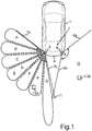
- a motor vehicle 1 illustrated in Fig. 1 is for example a passenger car.
- the motor vehicle 1 includes a driver assistance device 2 assisting the driver in driving the motor vehicle 1.
- a driver assistance device 2 assisting the driver in driving the motor vehicle 1.
- it can be a blind spot warning and/or a lane change assist and/or a cross traffic alert and/or a door opening assist and/or a rear pre-crash.
- Two radar sensors 5, 6 are associated with the driver assistance device 2, which are disposed behind a rear bumper 4 of the motor vehicle 1.
- the first radar sensor 5 is disposed in a left rear corner region of the motor vehicle 1, while the second radar sensor 6 is disposed in a right rear corner region. Both radar sensors 5, 6 are located behind the bumper 4 and are therefore not visible from the outside of the motor vehicle 1.
- the radar sensors 5, 6 are frequency-modulated continuous wave radar sensors (FMCW) in the embodiment.
- the radar sensors 5, 6 each have an azimuth detection range ⁇ , which is bounded by two lines 7a, 7b (for the left radar sensor 5) and 8a, 8b (for the right radar sensor 6), respectively, in Fig. 1 .
- the azimuth detection angle ⁇ is for example 150°.
- a field of view 9 and 10, respectively, of the respective radar sensor 5, 6 in azimuth direction and thus in horizontal direction is respectively defined.
- the fields of view 9, 10 can also overlap each other such that an overlap region 11 exists.
- Each radar sensor 5, 6 includes an integrated computing device for example in the form of a digital signal processor, which drives the radar sensor 5, 6 and additionally processes and evaluates the received signals.
- an external computing device common to the two sensors 5, 6 can also be provided, which is able to then process the received signals of the two sensors 5, 6.
- the radar sensors 5, 6 can detect target objects 12a (on the left) and 12b (on the right) external to vehicle. In particular, the radar sensors 5, 6 can determine the distance of the target objects 12a and 12b, respectively, from the respective radar sensor 5, 6 as well as respectively the target angle and the relative velocity of the target objects 12a and 12b, respectively, with respect to the motor vehicle 1 - they are measured variables of the radar sensors 5, 6.
- the radar sensor 5 - and analogously also the sensor 6 - can successively irradiate various partial ranges A, B, C, D, E, F, G of the azimuthal field of view 9.
- These partial ranges A to G represent angular ranges, wherein for successively covering the partial ranges A to G for example a transmit lobe of the transmitting antenna of the radar sensor 5 is electronically pivoted in azimuth direction, namely according to the phase array principle.
- the different orientations of the transmit lobe are schematically indicated for the different partial ranges A to G in Fig. 1 .
- the receiving antennas of the radar sensor 5 can overall have a wide receive characteristic in azimuth direction, with which the entire azimuthal field of view 9 is covered. Other configurations can alternatively realize narrow reception angle ranges in association with wide transmit lobes.
- Fig. 1 for the sake of clarity, only the partial ranges A to G of the field of view 9 of the first radar sensor 5 are illustrated. However, correspondingly, the horizontal field of view 10 of the second radar sensor 6 is here also divided in multiple partial ranges. Although the further description relates to the mode of operation of the first sensor 5, the mode of operation of the second sensor 6 corresponds to that of the first sensor 5.
- the number of the partial ranges A to G is only exemplarily illustrated in Fig. 1 and can be different according to embodiment. In the embodiment, a total of seven partial ranges A to G is provided, which are illuminated one after the other by the radar sensor 5.
- the mode of operation of the radar sensor 5 is as follows: in a single measurement cycle of the radar sensor 5, the main lobe of the transmitting antenna is once stepwise pivoted from the partial range A up to the partial range G, such that the partial ranges A to G are illuminated one after the other. Therein, for each partial range A to G, a temporal sequence of frequency-modulated chirp signals (chirps) is respectively emitted. First, such a sequence of chirp signals is emitted for the partial range A. After a preset transmission pause, then, a sequence of chirp signals is emitted to the partial range B. After a further preset transmission pause, then, the partial range C is irradiated etc. As is apparent from Fig.
- the radar sensor 5 has a larger reach for the partial range G than for the remaining partial ranges A to F. This is achieved in that the emitted sequence has more chirp signals for the partial range G than for the remaining ranges A to F. While for example 16 chirp signals are emitted within the respective sequence for the partial ranges A to F, for example a total of 64 chirp signals within the sequence is emitted for the partial range G.
- the detection of the target objects 12a, 12b is therefore individually and separately effected for each partial range A to G. Thus, it is possible to track the target objects 12a, 12b in the entire field of view 9, 10.
- a total of seven sequences of frequency-modulated chirp signals is emitted, namely a sequence of 16 chirp signals for the partial ranges A to F respectively as well as a sequence of 64 chirp signals for the partial range G.
- the received signals also each include a plurality of chirp signals.
- the received signal for the partial range A includes - if reflection on a target object occurs - 16 chirp signals; the received signal for the partial range B also includes 16 chirp signals, and the respective received signals for the partial ranges C to F also each include 16 chirp signals.
- the received signal from the partial range G includes 64 chirp signals.
- the received signals of the radar sensor 5 do not only include useful signals from the target object, but are also affected by interference signals.
- interference signals superimposed on the received signal can for example originate from the other radar sensor 6 or else from extraneous sources external to vehicle, such as for example from sensors of other vehicles or the like. These interferences are now detected and suppressed or filtered out in the received signal of the radar sensor 5.
- the detection and/or the suppression of the interference are effected separately and individually for each partial range A to G.
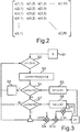
- An exemplary receive matrix provided based on a received signal for one of the partial ranges A to G is illustrated in Fig. 2 .
- the received signal including the plurality of chirp signals e.g. 16 chirp signals
- the baseband e.g. 16 chirp signals
- the samples of a single chirp signal are then combined in a common line of the receive matrix such that each line of the receive matrix includes the samples of an entire single chirp signal.
- the samples of the received signal are denoted by s(i,n).
- the interference For each received signal - and thus for each receive matrix - the interference is individually detected and suppressed. The interference is also detected and suppressed individually for each chirp signal within the receive matrix and thus individually for each line of the receive matrix.
- two different methods for detecting the interference are described. In the operation of the radar sensor 5 (and also of the radar sensor 6 separately) at least one of the two methods is thereby applied.
- the two methods can also be combined with each other and the results then be compared to each other and thus made plausible.
- the interference in a certain chirp signal (a certain line of the receive matrix) is detected in the manner that the samples of this chirp signal are each individually compared to a sample of an adjacent, in particular of an immediately succeeding chirp signal.
- the comparison is effected between each two samples of adjacent chirp signals, which (the samples) have the same row position (index n) within the respective row of samples.
- a difference between the two samples is determined, and then it is decided whether or not these two samples are affected by interference based on the amount of the difference. This decision is made in binary manner. This means that a sample can be interpreted either as free of interference or else as affected by interference.
- the computing device of the radar sensor 5 then checks for each sample whether the amount of the difference is greater than a preset limit value.
- the two samples s(i chirp +1,n sample ) as well as s(i chirp ,n sample ) are interpreted as affected by interference.
- a first step S1 the receive matrix s with samples is provided. Each line of the receive matrix s is then separately processed one after the other.
- a counter value j is implemented, which is incremented, thus respectively increased by one, from 1 to N-k.
- N denotes the number of the samples within a line of the receive matrix and is for example equal to 256
- a subset of samples s(j:j+k) within the examined line is defined.
- the subset can include a total of five samples, namely five immediately consecutive samples of the same line of the receive matrix and therefore of the same chirp signal.
- a parameter value is determined, which characterizes a deviation of these samples s(j) to s(j+k) from each other and thus a dispersion of the samples within the examined subset.
- the local variance LocVar of these samples s(j) to s(j+k) is determined as the parameter value.
- step S4 the computing device checks whether the parameter value LocVar is greater than a first threshold value G1.
- This first threshold value G1 is calculated from an intermediate value ZV by multiplication of this intermediate value ZV by a variable x in step S5.
- the variable x can for example be set to 11.
- step S6 the method proceeds to a step S6, in which the following is implemented: first, one of the samples, in particular the sample s(j+2), is interpreted as affected by interference and identified as such. If the preceding sample, in particular the sample s(j+1), of the same line was not identified as affected by interference and additionally the second preceding sample, in particular the sample s(j), was identified as affected by interference, the immediately preceding sample (s(j+1)) is also interpreted as affected by interference and identified as such. The method then returns to step S2, in which the counter value j is incremented.
- step S4 determines whether or not the parameter value LocVar is smaller than the first threshold value G1
- the method proceeds to a further step S7, in which is it checked by the computing device whether or not the intermediate value ZV is to be adapted and thus to be set to a new value.
- the parameter value LocVar is compared to a second threshold value G2. If the parameter value LocVar is greater than the second threshold value G2, thus, the method returns to step S2, in which the counter value j is incremented. However, if the parameter value LocVar is smaller than the second threshold value G2, thus, the intermediate value ZV is adapted.
- the second threshold value G2, too, is calculated immediately from the intermediate value ZV, namely by multiplication of the intermediate value ZV by a constant y according to step S8.
- This constant y is smaller than the constant x and is for example 3. Both values x, y can optionally also be variably set and thus be varied in operation.
- the first threshold value G1 is therefore greater than the second threshold value G2. Since the threshold values G1 and G2 are directly calculated from the intermediate value ZV, the adaptation of the two threshold values G1 and G2 is effected at the same time by variation of the intermediate value ZV. This means that the two threshold values G1, G2 are varied synchronously and proportionally to each other.
- step S7 If it is determined in step S7 that the parameter value LocVar is smaller than the second threshold value G2, thus, the adaptation of the intermediate value ZV is effected on the one hand and the method also returns to step S2 on the other hand.
- the adaptation of the intermediate value ZV is configured as follows: For the calculation of the new intermediate value ZV, a constant a is defined, which can for example be 0.0000075.
- step S9 the parameter value LocVar is multiplied by the constant a, and the result of this multiplication is supplied to an addition in step S10. The result of a multiplication of the current intermediate value ZV by the factor (1-a) is supplied to this addition as the second addend, which is performed in step S11.
- the intermediate value ZV and thus the threshold values G1 and G2 are therefore dynamically adjusted in the operation of the radar sensor 5, 6. This adjustment is preferably individually effected for each partial range A to G of the field of view 9, 10 of the radar sensor 5, 6.
- j N-k (e.g. 251) and the interference is detected in step S4 (LocVar > G1), all of the samples of this subset s(N-k) to s(N) are interpreted as affected by interference and identified as such.
- the values x and/or y and/or a can be adjusted individually for each partial range A to G.
- an interference matrix is generated as a result, in which it is separately specified to each sample, whether or not the interference has been detected in this sample.
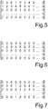
- An exemplary interference matrix is illustrated in Fig. 5 .
- the size of the interference matrix corresponds to the size of the receive matrix, wherein the samples affected by interference are designated by integers greater than zero.
- the samples, in which interference was not detected, are marked with "0".
- the samples within a common line, in which interference was detected and which are associated with one and the same interference are provided with serial numbers.
- the sample at the beginning of the interference is marked with "1", the next sample with "2", the further sample with "3” etc. up to the next sample, in which interference was not detected.
- the last sample of an interference is therefore marked with a number, which corresponds to the length of the interference, wherein the length of the interference is indicated by the number of the samples affected by interference.
- the distance between two interferences within a chirp signal tolerates at least two samples. If a distance of a single sample between two interferences is detected, thus, this sample is also marked as affected by interference and the two interferences are combined.
- interference from the fourth sample of the first chirp signal is detected, wherein the length of this interference is four samples.
- two interferences are respectively detected, wherein one of the interferences directly begins at the first sample.
- Fig. 4 temporal progresses of chirp signals of a received signal are illustrated (solid lines). The progress of the detected interferences (dashed lines) is also presented to each chirp signal. As is apparent from Fig. 4 , the decision is binary: either interference is detected in a certain sample or interference is not detected.
- the interference matrix is present, thus, the interference in the received signal (in the receive matrix) can be suppressed.
- the computing device of the radar sensor 5 a total of three different signal correction algorithms is stored, which serve for removing the interference from the received signal.
- the optimum signal correction algorithm is respectively individually selected in order to suppress the interference within this chirp signal.
- the selection is effected depending on the detected interference and in particular depending on the position of the interference within the respective chirp signal, depending on the position of the chirp signal within the sequence and/or depending on the length of the detected interference.
- the selection can also be effected individually for each detected interference.
- the following three signal correction algorithms are stored in the computing device:
- the first algorithm is selected for the samples of a certain chirp signal whenever at least in the immediately adjacent chirp signals, at least those samples are free of interference, which have the same row position within the respective chirp signal. With respect to the receive matrix, this means that the first algorithm is selected whenever the immediately adjacent samples located in the same column are free of interference.
- This second algorithm can also be selected only on condition that the length of the interference is smaller than a preset limit value, which can for example be 100 samples.
- exemplary interference matrices are illustrated.
- the first algorithm can be selected because the respectively (vertically) adjacent samples of the adjacent lines are free of interferences.
- the affected samples of the second line are therefore replaced with interpolated values, which are calculated by linear interpolation of the respective adjacent samples of the two adjacent lines.
- the second algorithm is respectively selected because the adjacent lines are also affected by interference or the interference is detected in the last line. Because the length of the interference is respectively smaller than 100, the second algorithm can be selected, in which the affected samples are replaced with interpolated values, which are calculated by linear interpolation of the adjacent samples of the same line.
- the interference as it is exemplarily illustrated in Fig. 4 can be completely eliminated, and the chirp signals can be "smoothed".
- the detection of the target objects is also effected considerably more precisely and reliably.
Landscapes
- Engineering & Computer Science (AREA)
- Radar, Positioning & Navigation (AREA)
- Remote Sensing (AREA)
- Physics & Mathematics (AREA)
- Computer Networks & Wireless Communication (AREA)
- General Physics & Mathematics (AREA)
- Electromagnetism (AREA)
- Radar Systems Or Details Thereof (AREA)
Claims (12)
- Verfahren zum Unterdrücken einer Störung in einem Empfangssignal (s), das durch einen Radarsensor (5, 6) eines Kraftfahrzeugs (1) empfangen wird, wobei zum Detektieren eines Zielobjekts (12) in einer Umgebung des Kraftfahrzeugs (1) ein Sendesignal, das eine Folge aufeinanderfolgender frequenzmodulierter Chirp-Signale enthält, mittels des Radarsensors (5, 6) abgestrahlt wird und ein Echosignal, das am Zielobjekt (12) reflektiert wurde, als das Empfangssignal (s) mit der überlagerten Störung empfangen wird, und wobei nach dem Empfangen des Empfangssignals (s) durch den Radarsensor (5, 6) die Störung des Empfangssignals (s) detektiert und im Empfangssignal (s) mittels einer elektronischen Recheneinrichtung unterdrückt wird, wobei mindestens zwei Signalkorrekturalgorithmen, die voneinander verschieden sind, zum Unterdrücken der Störung in der Recheneinrichtung gespeichert sind, wobei die Steuereinrichtung mindestens einen der mindestens zwei Signalkorrekturalgorithmen abhängig von der detektierten Störung wählt, um die Störung im Empfangssignal (s) zu unterdrücken, dadurch gekennzeichnet, dass
die Auswahl eines Signalkorrekturalgorithmus aus den mindestens zwei Signalkorrekturalgorithmen einzeln für jedes Chirp-Signal des Empfangssignals (s), in dem die Störung detektiert wird, bewirkt wird und dass die Auswahl des mindestens einen Signalkorrekturalgorithmus abhängig von Folgendem bewirkt wird:- der Position des Chirp-Signals, das durch eine Störung beeinträchtigt wird, in der Folge und- der Anzahl von Abtastwerten der Störung, die in einem Chirp-Signal unterdrückt werden soll. - Verfahren nach Anspruch 1, dadurch gekennzeichnet, dass
die Auswahl des mindestens einen Signalkorrekturalgorithmus für ein Chirp-Signal abhängig von der Position der Störung in diesem Chirp-Signal bewirkt wird. - Verfahren nach einem der vorhergehenden Ansprüche, dadurch gekennzeichnet, dass
sich mindestens zwei Signalkorrekturalgorithmen darin unterscheiden, ob die Abtastwerte des Empfangssignals (s), in dem die Störung detektiert wird, durch interpolierte Werte oder durch einen voreingestellten Wert ersetzt werden. - Verfahren nach einem der vorhergehenden Ansprüche, dadurch gekennzeichnet, dass
sich mindestens zwei Signalkorrekturalgorithmen darin unterscheiden, ob interpolierte Werte, mit denen Abtastwerte des Empfangssignals (s) in einem Chirp-Signal ersetzt werden, durch Interpolation weiterer Abtastwerte im selben Chirp-Signal oder durch Interpolation von Abtastwerten benachbarter Chirp-Signale bereitgestellt werden. - Verfahren nach einem der vorhergehenden Ansprüche, dadurch gekennzeichnet, dass
gemäß einem ersten Signalkorrekturalgorithmus Abtastwerte eines Chirp-Signals des Empfangssignals (s) durch interpolierte Werte ersetzt werden, die durch Interpolation von Abtastwerten benachbarter Chirp-Signale bereitgestellt werden. - Verfahren nach Anspruch 5, dadurch gekennzeichnet, dass
der erste Signalkorrekturalgorithmus zum Unterdrücken der Störung in einem Chirp-Signal gewählt wird, wenn mindestens in den unmittelbar benachbarten Chirp-Signalen derselben Folge mindestens die Abtastwerte frei von Störungen sind, die dieselbe Zeilenposition im entsprechenden Chirp-Signal besitzen wie die zu ersetzenden Abtastwerte. - Verfahren nach einem der vorhergehenden Ansprüche, dadurch gekennzeichnet, dass
gemäß einem zweiten Signalkorrekturalgorithmus Abtastwerte eines Chirp-Signals des Empfangssignals (s) durch interpolierte Werte ersetzt werden, die durch Interpolation benachbarter Abtastwerte desselben Chirp-Signals bereitgestellt werden. - Verfahren nach Anspruch 7, dadurch gekennzeichnet, dass
der zweite Signalkorrekturalgorithmus zum Unterdrücken der Störung in einem Chirp-Signal nur unter der Bedingung gewählt wird, dass die Anzahl der zu ersetzenden Abtastwerte in diesem Chirp-Signal kleiner als ein voreingestellter Grenzwert ist. - Verfahren nach Anspruch 7 oder 8, dadurch gekennzeichnet, dass
der zweite Signalkorrekturalgorithmus zum Unterdrücken der Störung in einem Chirp-Signal gewählt wird, wenn das Chirp-Signal ein erstes oder ein letztes Chirp-Signal der Folge ist oder eine Störung in unmittelbar benachbarten Chirp-Signalen derselben Folge detektiert wird. - Verfahren nach einem der vorhergehenden Ansprüche, dadurch gekennzeichnet, dass
gemäß einem dritten Signalkorrekturalgorithmus Abtastwerte eines Chirp-Signals des Empfangssignals (s) durch einen voreingestellten Wert ersetzt werden. - Verfahren nach Anspruch 10, dadurch gekennzeichnet, dass
der dritte Signalkorrekturalgorithmus zum Unterdrücken der Störung in einem Chirp-Signal gewählt wird, wenn die folgenden zwei Bedingungen gleichzeitig erfüllt sind:- die Anzahl der zu ersetzenden Abtastwerte in diesem Chirp-Signal ist größer als ein voreingestellter Grenzwert und- dieses Chirp-Signal ist ein erstes oder ein letztes Chirp-Signal der Folge oder eine Störung wird in unmittelbar benachbarten Chirp-Signalen derselben Folge detektiert. - Fahrerunterstützungsvorrichtung (2) für ein Kraftfahrzeug (1), die einen Radarsensor (5, 6) enthält, der zum Abstrahlen eines Sendesignals, das eine Folge aufeinanderfolgender frequenzmodulierter Chirp-Signale enthält, und zum Empfangen eines Echosignals, das an einem Zielobjekt (12) reflektiert wurde, als das Empfangssignal (s) mit überlagerter Störung zum Detektieren des Zielobjekts (12) in einer Umgebung des Kraftfahrzeugs (1) gebildet ist, und eine elektronische Rechenvorrichtung enthält, die ausgelegt ist, die Störung des Empfangssignals (s) nach dem Empfangen des Empfangssignals (s) durch den Radarsensor (5, 6) zu detektieren und zu unterdrücken, wobei mindestens zwei Signalkorrekturalgorithmen, die voneinander verschieden sind, zum Unterdrücken der Störung im Empfangssignal (s) in der Recheneinrichtung gespeichert sind, wobei die Recheneinrichtung ausgelegt ist, mindestens einen der mindestens zwei Signalkorrekturalgorithmen abhängig von der detektierten Störung zu wählen und die Störung im Empfangssignal (s) gemäß dem gewählten Signalkorrekturalgorithmus zu unterdrücken, dadurch gekennzeichnet, dass die Auswahl eines Signalkorrekturalgorithmus aus den mindestens zwei Signalkorrekturalgorithmen einzeln für jedes Chirp-Signal des Empfangssignals (s), in dem die Störung detektiert wird, bewirkt wird und dass die Auswahl des mindestens einen Signalkorrekturalgorithmus abhängig von Folgendem bewirkt wird:- der Position des Chirp-Signals, das durch eine Störung beeinträchtigt wird, in der Folge und- der Anzahl von Abtastwerten der Störung, die unterdrückt werden soll, in einem Chirp-Signal.
Applications Claiming Priority (2)
| Application Number | Priority Date | Filing Date | Title |
|---|---|---|---|
| DE102012021240.2A DE102012021240A1 (de) | 2012-10-27 | 2012-10-27 | Verfahren zum Unterdrücken einer Interferenz in einem Empfangssignal einesRadarsensors eines Kraftfahrzeugs und entsprechende Fahrerassistenzeinrichtung |
| PCT/EP2013/069043 WO2014063865A1 (en) | 2012-10-27 | 2013-09-13 | Method for suppressing interference in a received signal of a radar sensor of a motor vehicle and corresponding driver assistance device |
Publications (2)
| Publication Number | Publication Date |
|---|---|
| EP2912486A1 EP2912486A1 (de) | 2015-09-02 |
| EP2912486B1 true EP2912486B1 (de) | 2020-09-09 |
Family
ID=49162161
Family Applications (1)
| Application Number | Title | Priority Date | Filing Date |
|---|---|---|---|
| EP13760065.6A Active EP2912486B1 (de) | 2012-10-27 | 2013-09-13 | Verfahren zur unterdrückung von störungen in einem empfangenen signal eines radarsensors eines kraftfahrzeugs und entsprechende fahrerassistenzvorrichtung |
Country Status (4)
| Country | Link |
|---|---|
| US (1) | US20150260828A1 (de) |
| EP (1) | EP2912486B1 (de) |
| DE (1) | DE102012021240A1 (de) |
| WO (1) | WO2014063865A1 (de) |
Cited By (1)
| Publication number | Priority date | Publication date | Assignee | Title |
|---|---|---|---|---|
| TWI866150B (zh) * | 2023-04-07 | 2024-12-11 | 廣達電腦股份有限公司 | 雷達偵測裝置及方法 |
Families Citing this family (18)
| Publication number | Priority date | Publication date | Assignee | Title |
|---|---|---|---|---|
| DE102014114110A1 (de) | 2014-09-29 | 2016-03-31 | Hella Kgaa Hueck & Co. | Radarsensor |
| US20160252610A1 (en) * | 2015-02-26 | 2016-09-01 | Delphi Technologies, Inc. | Blind-spot radar system with improved semi-trailer tracking |
| EP3173812B1 (de) | 2015-11-24 | 2021-01-06 | Veoneer Sweden AB | Kraftfahrzeug-radarsystem zur verringerung von interferenzen |
| EP3267220A1 (de) * | 2016-07-08 | 2018-01-10 | Autoliv Development AB | Fahrzeugradarsystem |
| EP4099056A1 (de) * | 2016-10-07 | 2022-12-07 | Arriver Software AB | Zur verringerung von interferenzen angeordnetes fahrzeugradarsystem |
| EP3444628A1 (de) | 2017-08-18 | 2019-02-20 | Nxp B.V. | Radareinheit, integrierte schaltung und verfahren zur detektion und abschwächung von gegenseitiger interferenz |
| US11656321B2 (en) * | 2018-07-23 | 2023-05-23 | Richwave Technology Corp. | Method of microwave motion detection with adaptive frequency control and related devices |
| EP3637127B1 (de) | 2018-10-12 | 2024-11-27 | Axis AB | Verfahren, vorrichtung und system zur interferenzreduktion in einer frequenzmodulierten dauerstrichradareinheit |
| DE102018132745B4 (de) | 2018-12-18 | 2022-05-05 | Infineon Technologies Ag | Fmcw radar mit störsignalunterdrückung im zeitbereich |
| TWI705913B (zh) * | 2019-05-09 | 2020-10-01 | 鼎天國際股份有限公司 | 具視野大於160度之車輛輔助功能之雷達系統 |
| CN112083419B (zh) * | 2019-05-27 | 2023-12-26 | 鼎天国际股份有限公司 | 具视野大于160度的车辆辅助功能的雷达系统 |
| EP4015161B1 (de) * | 2019-09-13 | 2024-08-14 | Samsung Electronics Co., Ltd. | Mobile vorrichtung zum detektieren von objekten und betriebsverfahren dafür |
| EP4214544A1 (de) * | 2020-09-21 | 2023-07-26 | Google LLC | Intelligente heimvorrichtung mit einem einzelnen radarübertragungsmodus zur aktivitätserkennung von aktiven benutzern und vitalzeichenüberwachung von inaktiven benutzern |
| CN113093124B (zh) * | 2021-04-07 | 2022-09-02 | 哈尔滨工程大学 | 一种基于dqn算法的雷达干扰资源实时分配方法 |
| CN113433523B (zh) * | 2021-06-17 | 2022-09-16 | 同济大学 | 一种基于双框架循环rls的汽车雷达干扰抑制方法 |
| US12047101B2 (en) * | 2021-09-24 | 2024-07-23 | Apple Inc. | Background noise recorder |
| US12392863B2 (en) * | 2022-06-15 | 2025-08-19 | Nxp Usa, Inc. | Frequency-Modulated Continuous-Wave (FMCW) radar interference mitigation using an Autoregressive Moving Average (ARMA) model |
| EP4321901B1 (de) * | 2022-08-11 | 2025-12-24 | Nxp B.V. | Zieldetektionsverfahren und -system |
Citations (4)
| Publication number | Priority date | Publication date | Assignee | Title |
|---|---|---|---|---|
| US6094160A (en) * | 1999-06-10 | 2000-07-25 | Delco Electronics Corp. | Interference rejection method for an automotive radar CW/ICC system |
| US20060125682A1 (en) * | 2004-12-15 | 2006-06-15 | Kelly Thomas M Jr | System and method for reducing a radar interference signal |
| US7728762B2 (en) * | 2007-03-20 | 2010-06-01 | Denso Corporation | Method for detecting interference in radar system and radar using the same |
| US20110292988A1 (en) * | 2010-05-27 | 2011-12-01 | Mitsubishi Electric Corporation | Classification of interference |
Family Cites Families (12)
| Publication number | Priority date | Publication date | Assignee | Title |
|---|---|---|---|---|
| US4710772A (en) * | 1985-12-05 | 1987-12-01 | Raytheon Company | Log magnitude pulse interference detection for a radar system |
| EP0932838B1 (de) | 1996-10-17 | 2007-02-14 | Saab Bofors Dynamics AB | Verfahren zur störungsunterdrückung in einem fmcw-radar |
| NL1005067C2 (nl) * | 1997-01-23 | 1998-07-27 | Hollandse Signaalapparaten Bv | Radarapparaat. |
| EP0887658B1 (de) * | 1997-06-27 | 2004-08-25 | EADS Deutschland GmbH | Füllstandmessradargerät |
| JP4747652B2 (ja) * | 2005-04-15 | 2011-08-17 | 株式会社デンソー | Fmcwレーダ |
| US7375676B1 (en) * | 2006-03-07 | 2008-05-20 | Lockheed Martin Corporation | Mutual interference processor for pulse radar |
| JP4519797B2 (ja) * | 2006-03-30 | 2010-08-04 | 富士通テン株式会社 | 車載レーダ装置及び車載レーダ管制システム |
| WO2011002316A1 (en) * | 2009-07-01 | 2011-01-06 | Andrew Corbett | Signal processing system and method |
| DE102009057191A1 (de) | 2009-12-05 | 2011-06-09 | Valeo Schalter Und Sensoren Gmbh | Verfahren zum eindeutigen Bestimmen einer Entfernung und/oder einer relativen Geschwindigkeit eines Objektes, Fahrerassistenzeinrichtung und Kraftfahrzeug |
| EP2390679B1 (de) | 2010-05-27 | 2012-10-03 | Mitsubishi Electric R&D Centre Europe B.V. | Automobilradar mit Funkfrequenzstörungsvermeidung |
| JP5607428B2 (ja) * | 2010-06-03 | 2014-10-15 | 古野電気株式会社 | 信号処理装置、レーダ装置、信号処理方法、および信号処理プログラム |
| DE102011079615A1 (de) * | 2011-07-22 | 2013-01-24 | Robert Bosch Gmbh | FMCW-Radarsystem und Interferenzerkennungsverfahren für FMCW-Radarsysteme |
-
2012
- 2012-10-27 DE DE102012021240.2A patent/DE102012021240A1/de not_active Withdrawn
-
2013
- 2013-09-13 EP EP13760065.6A patent/EP2912486B1/de active Active
- 2013-09-13 WO PCT/EP2013/069043 patent/WO2014063865A1/en not_active Ceased
- 2013-09-13 US US14/436,990 patent/US20150260828A1/en not_active Abandoned
Patent Citations (4)
| Publication number | Priority date | Publication date | Assignee | Title |
|---|---|---|---|---|
| US6094160A (en) * | 1999-06-10 | 2000-07-25 | Delco Electronics Corp. | Interference rejection method for an automotive radar CW/ICC system |
| US20060125682A1 (en) * | 2004-12-15 | 2006-06-15 | Kelly Thomas M Jr | System and method for reducing a radar interference signal |
| US7728762B2 (en) * | 2007-03-20 | 2010-06-01 | Denso Corporation | Method for detecting interference in radar system and radar using the same |
| US20110292988A1 (en) * | 2010-05-27 | 2011-12-01 | Mitsubishi Electric Corporation | Classification of interference |
Non-Patent Citations (1)
| Title |
|---|
| BROOKER G M: "Mutual Interference of Millimeter-Wave Radar Systems", IEEE TRANSACTIONS ON ELECTROMAGNETIC COMPATIBILITY, IEEE SERVICE CENTER, NEW YORK, NY, US, vol. 49, no. 1, 1 February 2007 (2007-02-01), pages 170 - 181, XP011184082, ISSN: 0018-9375, DOI: 10.1109/TEMC.2006.890223 * |
Cited By (1)
| Publication number | Priority date | Publication date | Assignee | Title |
|---|---|---|---|---|
| TWI866150B (zh) * | 2023-04-07 | 2024-12-11 | 廣達電腦股份有限公司 | 雷達偵測裝置及方法 |
Also Published As
| Publication number | Publication date |
|---|---|
| US20150260828A1 (en) | 2015-09-17 |
| EP2912486A1 (de) | 2015-09-02 |
| WO2014063865A1 (en) | 2014-05-01 |
| DE102012021240A1 (de) | 2014-04-30 |
Similar Documents
| Publication | Publication Date | Title |
|---|---|---|
| US20150260828A1 (en) | Method for suppressing interference in a received signal of a radar sensor of a motor vehicle and corresponding driver assistance device | |
| US9897685B2 (en) | Method for detecting interference in a received signal of a radar sensor, driver assistance device and motor vehicle | |
| EP2912488B1 (de) | Verfahren zur detektion von störungen in einem empfangssignal eines radarsensors, fahrerassistenzvorrichtung und kraftfahrzeug | |
| JP6067870B2 (ja) | 自動車のレーダセンサを作動するための方法、ドライバー支援デバイス、及び自動車 | |
| US9604572B2 (en) | Method for maintaining a warning signal in a motor vehicle on the basis of the presence of a target object in a warning region, in particular a blind spot region, corresponding driver assistance system, and motor vehicle | |
| KR102445130B1 (ko) | 레이더 표적의 횡방향 상대 속도 성분을 확인하기 위한 방법 및 장치 | |
| US9702967B2 (en) | Method for setting a detection threshold for a received signal of a frequency-modulated continuous wave radar sensor of a motor vehicle on the basis of the noise level, radar sensor and motor vehicle | |
| EP4187275B1 (de) | Cfar-phasenarray-vorverarbeitung mit nichtkohärenter und kohärenter integration in kraftfahrzeugradarsystemen | |
| EP2998761B1 (de) | Radarsystem mit phasenbasierter mehrfachzielerkennung | |
| JP6304257B2 (ja) | レーダ装置、車両及び移動体速度検出方法 | |
| EP2944977B1 (de) | Radarsystem mit verbesserter mehrfachzielunterscheidung | |
| EP1326087B1 (de) | Vorrichtung und Verfahren zur Radardatenverarbeitung | |
| EP3267220A1 (de) | Fahrzeugradarsystem | |
| KR20120116921A (ko) | 객체까지의 간격 및/또는 객체의 상대 속도의 명확한 결정을 위한 방법, 운전자 보조 시스템, 및 자동차 | |
| US7532152B1 (en) | Automotive radar system | |
| JP3853642B2 (ja) | 自動車用レーダ装置 | |
| US12248092B2 (en) | Radar device | |
| US12554011B2 (en) | Method for operating a radar system for a vehicle |
Legal Events
| Date | Code | Title | Description |
|---|---|---|---|
| PUAI | Public reference made under article 153(3) epc to a published international application that has entered the european phase |
Free format text: ORIGINAL CODE: 0009012 |
|
| 17P | Request for examination filed |
Effective date: 20150330 |
|
| AK | Designated contracting states |
Kind code of ref document: A1 Designated state(s): AL AT BE BG CH CY CZ DE DK EE ES FI FR GB GR HR HU IE IS IT LI LT LU LV MC MK MT NL NO PL PT RO RS SE SI SK SM TR |
|
| AX | Request for extension of the european patent |
Extension state: BA ME |
|
| DAX | Request for extension of the european patent (deleted) | ||
| STAA | Information on the status of an ep patent application or granted ep patent |
Free format text: STATUS: EXAMINATION IS IN PROGRESS |
|
| 17Q | First examination report despatched |
Effective date: 20181022 |
|
| REG | Reference to a national code |
Ref country code: DE Ref legal event code: R079 Ref document number: 602013072383 Country of ref document: DE Free format text: PREVIOUS MAIN CLASS: G01S0007020000 Ipc: G01S0013420000 |
|
| GRAP | Despatch of communication of intention to grant a patent |
Free format text: ORIGINAL CODE: EPIDOSNIGR1 |
|
| STAA | Information on the status of an ep patent application or granted ep patent |
Free format text: STATUS: GRANT OF PATENT IS INTENDED |
|
| RIC1 | Information provided on ipc code assigned before grant |
Ipc: G01S 13/34 20060101ALI20200420BHEP Ipc: G01S 13/931 20200101ALI20200420BHEP Ipc: G01S 13/42 20060101AFI20200420BHEP Ipc: G01S 7/02 20060101ALI20200420BHEP |
|
| INTG | Intention to grant announced |
Effective date: 20200512 |
|
| GRAS | Grant fee paid |
Free format text: ORIGINAL CODE: EPIDOSNIGR3 |
|
| GRAA | (expected) grant |
Free format text: ORIGINAL CODE: 0009210 |
|
| STAA | Information on the status of an ep patent application or granted ep patent |
Free format text: STATUS: THE PATENT HAS BEEN GRANTED |
|
| AK | Designated contracting states |
Kind code of ref document: B1 Designated state(s): AL AT BE BG CH CY CZ DE DK EE ES FI FR GB GR HR HU IE IS IT LI LT LU LV MC MK MT NL NO PL PT RO RS SE SI SK SM TR |
|
| REG | Reference to a national code |
Ref country code: GB Ref legal event code: FG4D |
|
| REG | Reference to a national code |
Ref country code: AT Ref legal event code: REF Ref document number: 1312276 Country of ref document: AT Kind code of ref document: T Effective date: 20200915 Ref country code: CH Ref legal event code: EP |
|
| REG | Reference to a national code |
Ref country code: IE Ref legal event code: FG4D |
|
| REG | Reference to a national code |
Ref country code: DE Ref legal event code: R096 Ref document number: 602013072383 Country of ref document: DE |
|
| REG | Reference to a national code |
Ref country code: LT Ref legal event code: MG4D |
|
| PG25 | Lapsed in a contracting state [announced via postgrant information from national office to epo] |
Ref country code: FI Free format text: LAPSE BECAUSE OF FAILURE TO SUBMIT A TRANSLATION OF THE DESCRIPTION OR TO PAY THE FEE WITHIN THE PRESCRIBED TIME-LIMIT Effective date: 20200909 Ref country code: GR Free format text: LAPSE BECAUSE OF FAILURE TO SUBMIT A TRANSLATION OF THE DESCRIPTION OR TO PAY THE FEE WITHIN THE PRESCRIBED TIME-LIMIT Effective date: 20201210 Ref country code: NO Free format text: LAPSE BECAUSE OF FAILURE TO SUBMIT A TRANSLATION OF THE DESCRIPTION OR TO PAY THE FEE WITHIN THE PRESCRIBED TIME-LIMIT Effective date: 20201209 Ref country code: SE Free format text: LAPSE BECAUSE OF FAILURE TO SUBMIT A TRANSLATION OF THE DESCRIPTION OR TO PAY THE FEE WITHIN THE PRESCRIBED TIME-LIMIT Effective date: 20200909 Ref country code: BG Free format text: LAPSE BECAUSE OF FAILURE TO SUBMIT A TRANSLATION OF THE DESCRIPTION OR TO PAY THE FEE WITHIN THE PRESCRIBED TIME-LIMIT Effective date: 20201209 Ref country code: HR Free format text: LAPSE BECAUSE OF FAILURE TO SUBMIT A TRANSLATION OF THE DESCRIPTION OR TO PAY THE FEE WITHIN THE PRESCRIBED TIME-LIMIT Effective date: 20200909 Ref country code: LT Free format text: LAPSE BECAUSE OF FAILURE TO SUBMIT A TRANSLATION OF THE DESCRIPTION OR TO PAY THE FEE WITHIN THE PRESCRIBED TIME-LIMIT Effective date: 20200909 |
|
| REG | Reference to a national code |
Ref country code: AT Ref legal event code: MK05 Ref document number: 1312276 Country of ref document: AT Kind code of ref document: T Effective date: 20200909 |
|
| REG | Reference to a national code |
Ref country code: NL Ref legal event code: MP Effective date: 20200909 |
|
| PG25 | Lapsed in a contracting state [announced via postgrant information from national office to epo] |
Ref country code: RS Free format text: LAPSE BECAUSE OF FAILURE TO SUBMIT A TRANSLATION OF THE DESCRIPTION OR TO PAY THE FEE WITHIN THE PRESCRIBED TIME-LIMIT Effective date: 20200909 Ref country code: PL Free format text: LAPSE BECAUSE OF FAILURE TO SUBMIT A TRANSLATION OF THE DESCRIPTION OR TO PAY THE FEE WITHIN THE PRESCRIBED TIME-LIMIT Effective date: 20200909 Ref country code: LV Free format text: LAPSE BECAUSE OF FAILURE TO SUBMIT A TRANSLATION OF THE DESCRIPTION OR TO PAY THE FEE WITHIN THE PRESCRIBED TIME-LIMIT Effective date: 20200909 |
|
| PG25 | Lapsed in a contracting state [announced via postgrant information from national office to epo] |
Ref country code: NL Free format text: LAPSE BECAUSE OF FAILURE TO SUBMIT A TRANSLATION OF THE DESCRIPTION OR TO PAY THE FEE WITHIN THE PRESCRIBED TIME-LIMIT Effective date: 20200909 Ref country code: PT Free format text: LAPSE BECAUSE OF FAILURE TO SUBMIT A TRANSLATION OF THE DESCRIPTION OR TO PAY THE FEE WITHIN THE PRESCRIBED TIME-LIMIT Effective date: 20210111 Ref country code: SM Free format text: LAPSE BECAUSE OF FAILURE TO SUBMIT A TRANSLATION OF THE DESCRIPTION OR TO PAY THE FEE WITHIN THE PRESCRIBED TIME-LIMIT Effective date: 20200909 Ref country code: RO Free format text: LAPSE BECAUSE OF FAILURE TO SUBMIT A TRANSLATION OF THE DESCRIPTION OR TO PAY THE FEE WITHIN THE PRESCRIBED TIME-LIMIT Effective date: 20200909 Ref country code: CZ Free format text: LAPSE BECAUSE OF FAILURE TO SUBMIT A TRANSLATION OF THE DESCRIPTION OR TO PAY THE FEE WITHIN THE PRESCRIBED TIME-LIMIT Effective date: 20200909 Ref country code: EE Free format text: LAPSE BECAUSE OF FAILURE TO SUBMIT A TRANSLATION OF THE DESCRIPTION OR TO PAY THE FEE WITHIN THE PRESCRIBED TIME-LIMIT Effective date: 20200909 |
|
| REG | Reference to a national code |
Ref country code: CH Ref legal event code: PL |
|
| PG25 | Lapsed in a contracting state [announced via postgrant information from national office to epo] |
Ref country code: ES Free format text: LAPSE BECAUSE OF FAILURE TO SUBMIT A TRANSLATION OF THE DESCRIPTION OR TO PAY THE FEE WITHIN THE PRESCRIBED TIME-LIMIT Effective date: 20200909 Ref country code: AL Free format text: LAPSE BECAUSE OF FAILURE TO SUBMIT A TRANSLATION OF THE DESCRIPTION OR TO PAY THE FEE WITHIN THE PRESCRIBED TIME-LIMIT Effective date: 20200909 Ref country code: AT Free format text: LAPSE BECAUSE OF FAILURE TO SUBMIT A TRANSLATION OF THE DESCRIPTION OR TO PAY THE FEE WITHIN THE PRESCRIBED TIME-LIMIT Effective date: 20200909 Ref country code: IS Free format text: LAPSE BECAUSE OF FAILURE TO SUBMIT A TRANSLATION OF THE DESCRIPTION OR TO PAY THE FEE WITHIN THE PRESCRIBED TIME-LIMIT Effective date: 20210109 |
|
| REG | Reference to a national code |
Ref country code: DE Ref legal event code: R097 Ref document number: 602013072383 Country of ref document: DE |
|
| REG | Reference to a national code |
Ref country code: BE Ref legal event code: MM Effective date: 20200930 |
|
| PG25 | Lapsed in a contracting state [announced via postgrant information from national office to epo] |
Ref country code: LU Free format text: LAPSE BECAUSE OF NON-PAYMENT OF DUE FEES Effective date: 20200913 Ref country code: SK Free format text: LAPSE BECAUSE OF FAILURE TO SUBMIT A TRANSLATION OF THE DESCRIPTION OR TO PAY THE FEE WITHIN THE PRESCRIBED TIME-LIMIT Effective date: 20200909 Ref country code: MC Free format text: LAPSE BECAUSE OF FAILURE TO SUBMIT A TRANSLATION OF THE DESCRIPTION OR TO PAY THE FEE WITHIN THE PRESCRIBED TIME-LIMIT Effective date: 20200909 |
|
| PLBE | No opposition filed within time limit |
Free format text: ORIGINAL CODE: 0009261 |
|
| STAA | Information on the status of an ep patent application or granted ep patent |
Free format text: STATUS: NO OPPOSITION FILED WITHIN TIME LIMIT |
|
| 26N | No opposition filed |
Effective date: 20210610 |
|
| GBPC | Gb: european patent ceased through non-payment of renewal fee |
Effective date: 20201209 |
|
| PG25 | Lapsed in a contracting state [announced via postgrant information from national office to epo] |
Ref country code: DK Free format text: LAPSE BECAUSE OF FAILURE TO SUBMIT A TRANSLATION OF THE DESCRIPTION OR TO PAY THE FEE WITHIN THE PRESCRIBED TIME-LIMIT Effective date: 20200909 Ref country code: CH Free format text: LAPSE BECAUSE OF NON-PAYMENT OF DUE FEES Effective date: 20200930 Ref country code: BE Free format text: LAPSE BECAUSE OF NON-PAYMENT OF DUE FEES Effective date: 20200930 Ref country code: SI Free format text: LAPSE BECAUSE OF FAILURE TO SUBMIT A TRANSLATION OF THE DESCRIPTION OR TO PAY THE FEE WITHIN THE PRESCRIBED TIME-LIMIT Effective date: 20200909 Ref country code: IE Free format text: LAPSE BECAUSE OF NON-PAYMENT OF DUE FEES Effective date: 20200913 Ref country code: LI Free format text: LAPSE BECAUSE OF NON-PAYMENT OF DUE FEES Effective date: 20200930 |
|
| PG25 | Lapsed in a contracting state [announced via postgrant information from national office to epo] |
Ref country code: IT Free format text: LAPSE BECAUSE OF FAILURE TO SUBMIT A TRANSLATION OF THE DESCRIPTION OR TO PAY THE FEE WITHIN THE PRESCRIBED TIME-LIMIT Effective date: 20200909 |
|
| PG25 | Lapsed in a contracting state [announced via postgrant information from national office to epo] |
Ref country code: GB Free format text: LAPSE BECAUSE OF NON-PAYMENT OF DUE FEES Effective date: 20201209 |
|
| PG25 | Lapsed in a contracting state [announced via postgrant information from national office to epo] |
Ref country code: IS Free format text: LAPSE BECAUSE OF FAILURE TO SUBMIT A TRANSLATION OF THE DESCRIPTION OR TO PAY THE FEE WITHIN THE PRESCRIBED TIME-LIMIT Effective date: 20210109 Ref country code: TR Free format text: LAPSE BECAUSE OF FAILURE TO SUBMIT A TRANSLATION OF THE DESCRIPTION OR TO PAY THE FEE WITHIN THE PRESCRIBED TIME-LIMIT Effective date: 20200909 Ref country code: MT Free format text: LAPSE BECAUSE OF FAILURE TO SUBMIT A TRANSLATION OF THE DESCRIPTION OR TO PAY THE FEE WITHIN THE PRESCRIBED TIME-LIMIT Effective date: 20200909 Ref country code: CY Free format text: LAPSE BECAUSE OF FAILURE TO SUBMIT A TRANSLATION OF THE DESCRIPTION OR TO PAY THE FEE WITHIN THE PRESCRIBED TIME-LIMIT Effective date: 20200909 |
|
| PG25 | Lapsed in a contracting state [announced via postgrant information from national office to epo] |
Ref country code: MK Free format text: LAPSE BECAUSE OF FAILURE TO SUBMIT A TRANSLATION OF THE DESCRIPTION OR TO PAY THE FEE WITHIN THE PRESCRIBED TIME-LIMIT Effective date: 20200909 |
|
| P01 | Opt-out of the competence of the unified patent court (upc) registered |
Effective date: 20230528 |
|
| PGFP | Annual fee paid to national office [announced via postgrant information from national office to epo] |
Ref country code: DE Payment date: 20250916 Year of fee payment: 13 |
|
| PGFP | Annual fee paid to national office [announced via postgrant information from national office to epo] |
Ref country code: FR Payment date: 20250929 Year of fee payment: 13 |