EP2912342B1 - Clamping assembly - Google Patents
Clamping assembly Download PDFInfo
- Publication number
- EP2912342B1 EP2912342B1 EP13783353.9A EP13783353A EP2912342B1 EP 2912342 B1 EP2912342 B1 EP 2912342B1 EP 13783353 A EP13783353 A EP 13783353A EP 2912342 B1 EP2912342 B1 EP 2912342B1
- Authority
- EP
- European Patent Office
- Prior art keywords
- clamping
- springs
- assembly according
- clamping assembly
- release
- Prior art date
- Legal status (The legal status is an assumption and is not a legal conclusion. Google has not performed a legal analysis and makes no representation as to the accuracy of the status listed.)
- Active
Links
Images




Classifications
-
- F—MECHANICAL ENGINEERING; LIGHTING; HEATING; WEAPONS; BLASTING
- F16—ENGINEERING ELEMENTS AND UNITS; GENERAL MEASURES FOR PRODUCING AND MAINTAINING EFFECTIVE FUNCTIONING OF MACHINES OR INSTALLATIONS; THERMAL INSULATION IN GENERAL
- F16G—BELTS, CABLES, OR ROPES, PREDOMINANTLY USED FOR DRIVING PURPOSES; CHAINS; FITTINGS PREDOMINANTLY USED THEREFOR
- F16G11/00—Means for fastening cables or ropes to one another or to other objects; Caps or sleeves for fixing on cables or ropes
- F16G11/10—Quick-acting fastenings; Clamps holding in one direction only
- F16G11/105—Clamps holding in one direction only
- F16G11/108—Clamps holding in one direction only using a ball or a cylinder
-
- F—MECHANICAL ENGINEERING; LIGHTING; HEATING; WEAPONS; BLASTING
- F16—ENGINEERING ELEMENTS AND UNITS; GENERAL MEASURES FOR PRODUCING AND MAINTAINING EFFECTIVE FUNCTIONING OF MACHINES OR INSTALLATIONS; THERMAL INSULATION IN GENERAL
- F16G—BELTS, CABLES, OR ROPES, PREDOMINANTLY USED FOR DRIVING PURPOSES; CHAINS; FITTINGS PREDOMINANTLY USED THEREFOR
- F16G11/00—Means for fastening cables or ropes to one another or to other objects; Caps or sleeves for fixing on cables or ropes
- F16G11/04—Means for fastening cables or ropes to one another or to other objects; Caps or sleeves for fixing on cables or ropes with wedging action, e.g. friction clamps
- F16G11/044—Means for fastening cables or ropes to one another or to other objects; Caps or sleeves for fixing on cables or ropes with wedging action, e.g. friction clamps friction clamps deforming the cable, wire, rope or cord
- F16G11/048—Means for fastening cables or ropes to one another or to other objects; Caps or sleeves for fixing on cables or ropes with wedging action, e.g. friction clamps friction clamps deforming the cable, wire, rope or cord by moving a surface into the cable
-
- F—MECHANICAL ENGINEERING; LIGHTING; HEATING; WEAPONS; BLASTING
- F16—ENGINEERING ELEMENTS AND UNITS; GENERAL MEASURES FOR PRODUCING AND MAINTAINING EFFECTIVE FUNCTIONING OF MACHINES OR INSTALLATIONS; THERMAL INSULATION IN GENERAL
- F16B—DEVICES FOR FASTENING OR SECURING CONSTRUCTIONAL ELEMENTS OR MACHINE PARTS TOGETHER, e.g. NAILS, BOLTS, CIRCLIPS, CLAMPS, CLIPS OR WEDGES; JOINTS OR JOINTING
- F16B2/00—Friction-grip releasable fastenings
- F16B2/02—Clamps, i.e. with gripping action effected by positive means other than the inherent resistance to deformation of the material of the fastening
- F16B2/06—Clamps, i.e. with gripping action effected by positive means other than the inherent resistance to deformation of the material of the fastening external, i.e. with contracting action
- F16B2/12—Clamps, i.e. with gripping action effected by positive means other than the inherent resistance to deformation of the material of the fastening external, i.e. with contracting action using sliding jaws
-
- F—MECHANICAL ENGINEERING; LIGHTING; HEATING; WEAPONS; BLASTING
- F16—ENGINEERING ELEMENTS AND UNITS; GENERAL MEASURES FOR PRODUCING AND MAINTAINING EFFECTIVE FUNCTIONING OF MACHINES OR INSTALLATIONS; THERMAL INSULATION IN GENERAL
- F16B—DEVICES FOR FASTENING OR SECURING CONSTRUCTIONAL ELEMENTS OR MACHINE PARTS TOGETHER, e.g. NAILS, BOLTS, CIRCLIPS, CLAMPS, CLIPS OR WEDGES; JOINTS OR JOINTING
- F16B2/00—Friction-grip releasable fastenings
- F16B2/02—Clamps, i.e. with gripping action effected by positive means other than the inherent resistance to deformation of the material of the fastening
- F16B2/14—Clamps, i.e. with gripping action effected by positive means other than the inherent resistance to deformation of the material of the fastening using wedges
-
- F—MECHANICAL ENGINEERING; LIGHTING; HEATING; WEAPONS; BLASTING
- F16—ENGINEERING ELEMENTS AND UNITS; GENERAL MEASURES FOR PRODUCING AND MAINTAINING EFFECTIVE FUNCTIONING OF MACHINES OR INSTALLATIONS; THERMAL INSULATION IN GENERAL
- F16G—BELTS, CABLES, OR ROPES, PREDOMINANTLY USED FOR DRIVING PURPOSES; CHAINS; FITTINGS PREDOMINANTLY USED THEREFOR
- F16G11/00—Means for fastening cables or ropes to one another or to other objects; Caps or sleeves for fixing on cables or ropes
- F16G11/10—Quick-acting fastenings; Clamps holding in one direction only
-
- Y—GENERAL TAGGING OF NEW TECHNOLOGICAL DEVELOPMENTS; GENERAL TAGGING OF CROSS-SECTIONAL TECHNOLOGIES SPANNING OVER SEVERAL SECTIONS OF THE IPC; TECHNICAL SUBJECTS COVERED BY FORMER USPC CROSS-REFERENCE ART COLLECTIONS [XRACs] AND DIGESTS
- Y10—TECHNICAL SUBJECTS COVERED BY FORMER USPC
- Y10T—TECHNICAL SUBJECTS COVERED BY FORMER US CLASSIFICATION
- Y10T24/00—Buckles, buttons, clasps, etc.
- Y10T24/39—Cord and rope holders
- Y10T24/3969—Sliding part or wedge
-
- Y—GENERAL TAGGING OF NEW TECHNOLOGICAL DEVELOPMENTS; GENERAL TAGGING OF CROSS-SECTIONAL TECHNOLOGIES SPANNING OVER SEVERAL SECTIONS OF THE IPC; TECHNICAL SUBJECTS COVERED BY FORMER USPC CROSS-REFERENCE ART COLLECTIONS [XRACs] AND DIGESTS
- Y10—TECHNICAL SUBJECTS COVERED BY FORMER USPC
- Y10T—TECHNICAL SUBJECTS COVERED BY FORMER US CLASSIFICATION
- Y10T24/00—Buckles, buttons, clasps, etc.
- Y10T24/39—Cord and rope holders
- Y10T24/3969—Sliding part or wedge
- Y10T24/3973—Rope clamped between cone and socket
-
- Y—GENERAL TAGGING OF NEW TECHNOLOGICAL DEVELOPMENTS; GENERAL TAGGING OF CROSS-SECTIONAL TECHNOLOGIES SPANNING OVER SEVERAL SECTIONS OF THE IPC; TECHNICAL SUBJECTS COVERED BY FORMER USPC CROSS-REFERENCE ART COLLECTIONS [XRACs] AND DIGESTS
- Y10—TECHNICAL SUBJECTS COVERED BY FORMER USPC
- Y10T—TECHNICAL SUBJECTS COVERED BY FORMER US CLASSIFICATION
- Y10T24/00—Buckles, buttons, clasps, etc.
- Y10T24/39—Cord and rope holders
- Y10T24/3969—Sliding part or wedge
- Y10T24/3976—Sliding ball
Definitions
- This invention relates to clamping assemblies. More particularly, but not exclusively, this invention relates to clamping assemblies for clamping elongate articles, such as wires, wire ropes or the like. Embodiments of the invention relate to clamping assemblies comprising clamping members urged to a clamping condition by means of urging means.
- Patent specification No. GB2240581 discloses a connector comprising a body having a passage and clamping member for clamping a wire in the passage.
- releasing the wire can only be effected by manipulating the wire.
- US 5 572 770 A discloses a self locking cord lock according to the preamble of claim 1.
- GB 2 378 999 A discloses suspending equipment using a wedge-type locking device.
- a clamping assembly comprising a body defining a passage through which an elongate article can extend, a clamping member arranged in the passage for clamping the elongate article, the clamping member being movable between clamping and release conditions for respectively clamping and releasing the article, and urging means comprising a pair of springs to urge the clamping member to the clamping position, wherein the springs extend externally of the body opposite each other and can be deformed by pressing the pair of springs towards each other to a release configuration to urge the clamping member to the release condition.
- the urging means may provide a release means for urging the clamping member to the release condition.
- the springs may comprise tension springs.
- the springs may be deformable to a deformed configuration by applying a release force thereto.
- the springs can be deformed by applying the release force thereto transverse to the direction of movement of the clamping member between the clamping and release conditions.
- the release force may be applied in a direction towards the body.
- the deformation of the springs desirably urges the clamping member to the release condition.
- the application of the release force to the springs causes the springs to push the clamping member to the release condition.
- the urging means may hold the clamping member.
- the urging means may comprise a carriage attached to the spring, wherein the carriage carries the clamping member.
- the carriage may define a space in which the clamping member is received.
- the clamping assembly may further include anchor means to anchor the urging means to the body.
- the anchor means may comprise an anchor portion and the body may include cooperating means to cooperate with the anchor portion and anchor the urging means to the body.
- the cooperating means may comprise a holding formation for holding the anchor portion.
- the holding formation may be an aperture or recess to receive the anchor portion.
- the aperture or recess may be defined in the body.
- the urging means may include the anchor portion.
- the anchor portion may be attached to each spring by an attaching member.
- the holding formation may be a slot to receive the anchor portion.
- the slot may be an upwardly facing slot.
- the slot may be a side facing slot.
- Each spring may be attached to the carriage.
- the anchor member may be attached to both springs by the attaching member.
- Each spring may extend externally of the body.
- Each spring may comprise an elongate strip, which may be a substantially flat strip.
- the anchor portion may extend between the pair of springs, and may comprise a connecting member to connect the springs to each other.
- the connecting member may be substantially flat.
- Each spring may comprise an elongate curved member.
- the curved member may curve outwardly way from the body.
- the urging means may be in the form of a ring.
- Each spring may comprise a flat spring.
- the urging means may be deformed by pressing the pair of springs towards each other. Both springs may be pressed towards the body to effect said movement of the clamping member to the release condition.
- the clamping member may comprise a roller, which may be in the form of a cylindrical member or a ball. Alternatively, the clamping member may comprise a wedge.
- the body may comprise a first wall partly defining said passage.
- the clamping member may be movable substantially parallel to said first wall.
- the clamping member may clamp the elongate article against the first wall.
- the body may include a second wall partly defining said passage, the second wall extending at an acute angle to said first wall.
- the clamping member may be movable along said passage from the release condition to the clamping condition.
- the carriage may have a first face substantially parallel to the first wall and a second face substantially parallel to the second wall.
- the second wall may be a reaction wall to apply a reaction force to said clamping member when the clamping member clamps the article against the first wall.
- the second wall may taper towards the first wall in the direction in which the clamping member moves from the release condition to the clamping condition.
- Each spring may be formed of a plastics material.
- the clamping assembly may include securing means for securing the clamping assembly to an ancillary member.
- the securing means may comprise a securing member, which may be configured to be received by a portion of the ancillary member, or which may be configured to receive a portion of the ancillary member.
- the securing means may comprise a recess which can receive a projection on the ancillary member.
- the recess may be defined by the body.
- the securing means may comprise a projection which can be received by a recess defined by the ancillary member.
- the body may define a pair of opposed recesses or a pair of opposed projections.
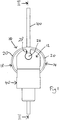
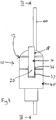
- the clamping assembly 10 for clamping an elongate article 100 in the form of a wire, wire rope or the like.
- the clamping assembly 10 comprises a body 12, urging means 14 and a clamping member 16 for clamping the elongate article within the body 12.
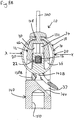
- the clamping member 16 is movable from a clamping condition shown in Figure 4A to a release condition shown in Figure 4B .
- the clamping member 16 is in the form of a cylindrical roller.
- the urging means 14 comprises a ring 18 formed of a pair of springs 20 in the form of tension springs.
- Each spring 20 is in the form of an elongate curved member, which curves outwardly away from the body 12, as shown most clearly in Figures 1 , 4A and 4B .
- Each spring 20 is in the form of a substantially flat strip.
- the urging means 14 further includes a carriage 22, in the form of a substantially square member, integrally attached to the springs 20.
- the springs 20 extend outwardly from the carriage 22 on opposite sides thereof.
- the carriage 22 defines a space 24 in which the clamping member 16 is carried.
- the urging means 14 also includes an anchor portion 26, which is attached to the springs 20 via an attaching member 28. Each spring 20 extends from the carriage 22 to the attaching member 28.
- the body 12 includes a domed upper region 30 defining a holding formation in the form of an upwardly facing slot 32.
- the anchor portion 26 is received in the upwardly facing slot 32 and held therein to secure the urging means 14 to the body 12.
- the body 12 further defines a passage 34 in which the carriage 22 and the clamping member 16 are held.
- the body 12 also includes a securing member in the form of a securing portion 38 opposite the upper region 30.
- the securing portion 38 is provided to secure the body 12 to an ancillary member 40 to attach the clamping assembly to, for example, a load, such as mounted on a threaded rod.
- the ancillary member 40 defines a mouth portion 42 to receive the securing portion 38, thereby securing the body 12 to the ancillary member 40.
- a first opening 36 is defined in the body 12, and extends across the securing portion 38 opposite the upper region 30.
- the first opening 36 provides communication between the passage 34 and the region outside the body 12.
- the first opening 36 allows the carriage 22 to be received in the passage 34.
- the springs 20 extend through the first opening 36 to the carriage 22 in the passage 34.
- the ancillary member 40 defines an associated second opening 37 which is aligned with the first opening 36 when the ancillary member 40 is secured to the body 12.
- the springs 20 extend from the attaching member 28 in opposite directions around the body 12 to the carriage 22 in the passage 34, through the first opening 36 and the associated opening 37.
- the passage 34 defined in the body 12 extends through the upper region 30 to a second opening 44 opposite the first opening 36.
- the elongate article 100 can extend through the passage 34, entering and exiting the body 12 via the first and second openings 36, 44.
- the passage 34 is defined between first and second internal walls 46, 48 of the body 12.
- the elongate article 100 extends along the first wall 46.
- the second wall 48 is arranged at an acute angle to the first wall 46, and tapers towards the first wall 46 in the direction from the first opening 36 to the second opening 44.
- the carriage 22 has a first face 50 which faces the first wall 46 and extends substantially parallel thereto.
- the carriage 22 also has a second face 52 which faces the second wall 48 and extends substantially parallel to the second wall 48.
- the ancillary member 40 is secured to the body 12, and the elongate article 100 is threaded through the passage 34 in the body 12 in the direction indicated by the arrow A in Figure 2 .
- the clamping assembly 10 is at a desired position on the elongate article 100, the elongate article 100 is then moved in the opposite direction, as indicated by the arrow B in Figure 2 .
- movement of the elongate article in the direction indicated by the arrow B, when the clamping member engages the elongate article 100 further pulls the carriage 22 and the clamping member 16 in the same direction.
- FIGS. 2 and 4A show the carriage 22 holding the clamping member 16 in the clamping condition in which the clamping member 16 clamps the elongate article 100.
- the position of the clamping assembly 10 along the elongate member 100 can be adjusted, for example, if the user realises that the clamping assembly 10 has been arranged on the elongate article 100 in the wrong position. This can be done by pressing inwardly on the springs 20 as shown by the arrows X in Figure 4A and 4B , to deform them to a release configuration shown in Figure 4B . Such deformation of the springs 20 pushes the carriage 22 and the clamping member 16 from the clamping condition shown in Figure 4A to the release condition shown in Figure 4B .
- the clamping member 16 When the clamping member 16 is in the release condition, the elongate article 100 is not clamped by the clamping member 16, thereby allowing the clamping assembly 10 to be moved along the elongate member 100 to the correct position. The clamping assembly 10 can then be clamped to the elongate article 100 as described above.
- the clamping member could be a spherical member or a wedge shaped member.
- clamping assembly 10 for clamping an elongate article 100, in which the clamping member 16 can be easily released from the clamping condition to the release condition by pressing inwardly on the springs 20.
- a second embodiment of the clamping assembly 10 is shown in Figures 6 to 9 .
- the second embodiment of the clamping assembly 10 includes many of the features of the first embodiment shown in Figures 1 to 5 .
- the features of the first embodiment that are present in the second embodiment are designated with the same reference numerals as in Figures 1 to 5 .
- the second embodiment differs from the first embodiment in that the upper region 30 defines a side facing slot 132.
- the urging means 14 comprises an anchor portion in the form of a substantially flat connecting member 126.
- the connecting member 126 connects the springs 20 to each other at the top of the urging means 14.
- the connecting member 126 is received in the side facing slot 132 from outside the body 12, and is thus held by the body 12.
- the connecting member 126 defines a cooperating recessed formation 127 to cooperate with a protrusion 128 in the side facing slot 132 (see Figures 7 , 8A and 8B ).
- the carriage 22 and the clamping member 16 are held in the passage 34 in the body 12 in the same way as the first embodiment.
- the second embodiment thus operates in the same way as the first embodiment.
- the body 12 includes a pair of opposed securing formations in the form of two recesses 138A, 138B defined by the body 12.
- An ancillary member 140 includes a pair of opposed projections 142A, 142B which can be received in the recesses 138A, 138B, thereby securing the ancillary member to the body 12.
- the ancillary member 140 includes a sloped wall 144 along which the elongate article 100 can extend when the elongate article 100 is clamped by the clamping member 16.
- the ancillary member may have a fastening formation 150, such as a threaded bore, to fasten a further article (not shown), such as a threaded rod, thereto.
- a fastening formation 150 such as a threaded bore
- Figures 8A and 8B show sectional views of the second embodiment of the clamping assembly 10 in the clamping and release conditions.
- Figure 8B shows the urging means 14 in a release configuration. These views are similar to the views shown in Figures 4A and 4B .
- the above described embodiments have the advantage that there is no need for an end cap. Instead the ancillary members 38, 140 are provided, which can be replaced by a different ancillary members 38, 140, thereby allowing the clamping assembly to perform different functions.
- the above described embodiments also have the advantage that the clamping member 16 is devoid of teeth, and can be formed of zinc, thereby reducing expense.
- the second embodiment has the further advantage that by providing a slot 132 in the side of the body 12, removal of the urging means 14, and the clamping member 16 is simplified.
Landscapes
- Engineering & Computer Science (AREA)
- General Engineering & Computer Science (AREA)
- Mechanical Engineering (AREA)
- Clamps And Clips (AREA)
- Dental Tools And Instruments Or Auxiliary Dental Instruments (AREA)
Priority Applications (1)
| Application Number | Priority Date | Filing Date | Title |
|---|---|---|---|
| PL13783353T PL2912342T3 (pl) | 2012-10-24 | 2013-10-18 | Zespół zaciskający |
Applications Claiming Priority (3)
| Application Number | Priority Date | Filing Date | Title |
|---|---|---|---|
| GBGB1219119.3A GB201219119D0 (en) | 2012-10-24 | 2012-10-24 | Clamping assembly |
| GB1318287.8A GB2509807B (en) | 2012-10-24 | 2013-10-16 | Clamping Assembly |
| PCT/GB2013/000441 WO2014064403A1 (en) | 2012-10-24 | 2013-10-18 | Clamping assembly |
Publications (2)
| Publication Number | Publication Date |
|---|---|
| EP2912342A1 EP2912342A1 (en) | 2015-09-02 |
| EP2912342B1 true EP2912342B1 (en) | 2018-10-10 |
Family
ID=47359410
Family Applications (1)
| Application Number | Title | Priority Date | Filing Date |
|---|---|---|---|
| EP13783353.9A Active EP2912342B1 (en) | 2012-10-24 | 2013-10-18 | Clamping assembly |
Country Status (16)
| Country | Link |
|---|---|
| US (1) | US9695908B2 (pl) |
| EP (1) | EP2912342B1 (pl) |
| JP (1) | JP6312687B2 (pl) |
| AU (1) | AU2013336485B2 (pl) |
| BR (1) | BR112015008584B1 (pl) |
| CA (1) | CA2888414C (pl) |
| CL (1) | CL2015001035A1 (pl) |
| DK (1) | DK2912342T3 (pl) |
| ES (1) | ES2702076T3 (pl) |
| GB (2) | GB201219119D0 (pl) |
| MX (1) | MX371183B (pl) |
| PL (1) | PL2912342T3 (pl) |
| PT (1) | PT2912342T (pl) |
| SA (1) | SA515360316B1 (pl) |
| WO (1) | WO2014064403A1 (pl) |
| ZA (1) | ZA201502689B (pl) |
Families Citing this family (7)
| Publication number | Priority date | Publication date | Assignee | Title |
|---|---|---|---|---|
| GB201414162D0 (en) | 2014-08-11 | 2014-09-24 | Gripple Ltd | Securing device |
| US10280957B2 (en) * | 2016-04-22 | 2019-05-07 | Helen Of Troy Limited | Cam lock mechanism |
| GB201701736D0 (en) | 2017-02-02 | 2017-03-22 | Gripple Ltd | Securing assembly |
| US10570991B2 (en) | 2017-02-08 | 2020-02-25 | Michael Aaron O'Rourke | Apparatus for quickly securing a cable |
| GB201801759D0 (en) * | 2018-02-02 | 2018-03-21 | Gripple Ltd | Clamping device |
| JP7114073B2 (ja) * | 2018-12-14 | 2022-08-08 | 鍋屋バイテック株式会社 | クランプユニット及びクランプ装置 |
| CA3190217A1 (en) | 2020-07-29 | 2022-02-03 | Ctking, Llc | Flexible u-bolt assembly |
Family Cites Families (17)
| Publication number | Priority date | Publication date | Assignee | Title |
|---|---|---|---|---|
| FR1060330A (fr) * | 1952-07-17 | 1954-04-01 | Goro | Dispositif pour la traction de l'extrémité d'une bande, d'un tapis transporteur par exemple, et appareil tendeur comportant ce dispositif |
| GB1273362A (en) * | 1967-10-17 | 1972-05-10 | Pasbrig Max | Connecting devices |
| FI69192C (fi) * | 1982-11-03 | 1985-12-10 | Suunto Oy | Snoerlaos |
| GB2210517B (en) * | 1987-09-26 | 1992-02-05 | Estate Wire Ltd | Connector for wires etc |
| US4881302A (en) * | 1988-07-07 | 1989-11-21 | Lee So Sun K | Cord or rod clamp |
| US4901402A (en) * | 1989-03-10 | 1990-02-20 | Begemann Malcolm J S | Clamping device |
| GB9000415D0 (en) | 1990-01-09 | 1990-03-07 | Gripple Ltd | Connector for wires,etc |
| FR2661804B3 (fr) * | 1990-05-11 | 1992-07-24 | Santoul Christian | Attache reglable pour cordonnets, lacets ou autres liens souples. |
| US5193252A (en) * | 1992-04-20 | 1993-03-16 | Svehaug Oswald C | Quick-release cleat |
| US5440788A (en) * | 1994-04-04 | 1995-08-15 | Boden; Robert O. | Cord lock of elastomeric material |
| JPH07313217A (ja) * | 1994-05-27 | 1995-12-05 | Nifco Inc | 紐止め具 |
| US5572770A (en) * | 1995-08-18 | 1996-11-12 | Boden; Robert O. | Self locking cord lock |
| FR2740663B1 (fr) * | 1995-11-08 | 1998-01-16 | Ykk France | Article pouvant constituer une butee reglable et amovible sur un element filiforme tel qu'un cordon vestimentaire de serrage ou de cintrage |
| DE19720335C1 (de) * | 1997-05-15 | 1998-11-19 | Joerg Feder | Längenverstellvorrichtung für Segelboot-Trapeze |
| GB0120524D0 (en) * | 2001-08-23 | 2001-10-17 | Gripple Ltd | Suspending equipment |
| ATE512485T1 (de) * | 2008-03-12 | 2011-06-15 | Gripple Ltd | Verbinder für draht oder ähnliches |
| GB2481849B (en) * | 2010-07-09 | 2012-10-03 | Tim James Ussher | Cord clamping device |
-
2012
- 2012-10-24 GB GBGB1219119.3A patent/GB201219119D0/en not_active Ceased
-
2013
- 2013-10-16 GB GB1318287.8A patent/GB2509807B/en active Active
- 2013-10-18 BR BR112015008584-9A patent/BR112015008584B1/pt active IP Right Grant
- 2013-10-18 US US14/434,696 patent/US9695908B2/en active Active
- 2013-10-18 ES ES13783353T patent/ES2702076T3/es active Active
- 2013-10-18 PL PL13783353T patent/PL2912342T3/pl unknown
- 2013-10-18 CA CA2888414A patent/CA2888414C/en active Active
- 2013-10-18 JP JP2015538554A patent/JP6312687B2/ja active Active
- 2013-10-18 PT PT13783353T patent/PT2912342T/pt unknown
- 2013-10-18 DK DK13783353.9T patent/DK2912342T3/en active
- 2013-10-18 WO PCT/GB2013/000441 patent/WO2014064403A1/en not_active Ceased
- 2013-10-18 EP EP13783353.9A patent/EP2912342B1/en active Active
- 2013-10-18 AU AU2013336485A patent/AU2013336485B2/en active Active
- 2013-10-18 MX MX2015005162A patent/MX371183B/es active IP Right Grant
-
2015
- 2015-04-21 SA SA515360316A patent/SA515360316B1/ar unknown
- 2015-04-21 ZA ZA2015/02689A patent/ZA201502689B/en unknown
- 2015-04-22 CL CL2015001035A patent/CL2015001035A1/es unknown
Non-Patent Citations (1)
| Title |
|---|
| None * |
Also Published As
| Publication number | Publication date |
|---|---|
| EP2912342A1 (en) | 2015-09-02 |
| US9695908B2 (en) | 2017-07-04 |
| BR112015008584B1 (pt) | 2021-07-27 |
| PT2912342T (pt) | 2018-12-19 |
| CA2888414A1 (en) | 2014-05-01 |
| MX2015005162A (es) | 2015-07-17 |
| CA2888414C (en) | 2018-06-12 |
| AU2013336485B2 (en) | 2016-09-01 |
| JP2015535328A (ja) | 2015-12-10 |
| BR112015008584A2 (pt) | 2017-10-03 |
| ES2702076T3 (es) | 2019-02-27 |
| PL2912342T3 (pl) | 2019-02-28 |
| WO2014064403A1 (en) | 2014-05-01 |
| GB201318287D0 (en) | 2013-11-27 |
| ZA201502689B (en) | 2016-01-27 |
| SA515360316B1 (ar) | 2018-05-29 |
| GB2509807B (en) | 2015-01-21 |
| GB2509807A (en) | 2014-07-16 |
| JP6312687B2 (ja) | 2018-04-18 |
| CL2015001035A1 (es) | 2015-10-23 |
| MX371183B (es) | 2020-01-22 |
| GB201219119D0 (en) | 2012-12-05 |
| US20150267774A1 (en) | 2015-09-24 |
| AU2013336485A1 (en) | 2015-05-07 |
| DK2912342T3 (en) | 2019-01-14 |
Similar Documents
| Publication | Publication Date | Title |
|---|---|---|
| CA2888414C (en) | Clamping assembly | |
| EP3129676B1 (en) | Improved gripping device | |
| EP3665394B1 (en) | Flange mounting clamp | |
| EP2109723B1 (en) | Wire termination device | |
| US11649878B2 (en) | Clamping device | |
| EP3237777B1 (en) | Improvements in or relating to clamping devices | |
| EP2616709B1 (en) | Improvements in or relating to clamping members and clamping devices | |
| EP2668419B1 (en) | Clamping assembly | |
| US7878547B2 (en) | Seatbelt anchor assembly | |
| GB2580575A (en) | Securing device | |
| CZ20003361A3 (en) | Dead-end clamp for an insulated overhead cable, especially a bundle assembled overhead cable | |
| EP2775167B1 (en) | Clamping device for wire ropes | |
| AU2002321453A1 (en) | Suspending equipment | |
| WO2021033205A1 (en) | Wedge cable gripper | |
| EP4240982B1 (en) | Improvements in or relating to carriages and clamping devices | |
| KR101655050B1 (ko) | 쐐기형 인장 클램프 | |
| WO2015092345A1 (en) | Gripping device | |
| JP2017210818A (ja) | 鎖保持器 |
Legal Events
| Date | Code | Title | Description |
|---|---|---|---|
| PUAI | Public reference made under article 153(3) epc to a published international application that has entered the european phase |
Free format text: ORIGINAL CODE: 0009012 |
|
| 17P | Request for examination filed |
Effective date: 20150521 |
|
| AK | Designated contracting states |
Kind code of ref document: A1 Designated state(s): AL AT BE BG CH CY CZ DE DK EE ES FI FR GB GR HR HU IE IS IT LI LT LU LV MC MK MT NL NO PL PT RO RS SE SI SK SM TR |
|
| AX | Request for extension of the european patent |
Extension state: BA ME |
|
| DAX | Request for extension of the european patent (deleted) | ||
| GRAP | Despatch of communication of intention to grant a patent |
Free format text: ORIGINAL CODE: EPIDOSNIGR1 |
|
| INTG | Intention to grant announced |
Effective date: 20180503 |
|
| RBV | Designated contracting states (corrected) |
Designated state(s): AL AT BE BG CH CY CZ DE DK EE ES FI FR GR HR HU IE IS IT LI LT LU LV MC MK MT NL NO PL PT RO RS SE SI SK SM TR |
|
| GRAS | Grant fee paid |
Free format text: ORIGINAL CODE: EPIDOSNIGR3 |
|
| GRAA | (expected) grant |
Free format text: ORIGINAL CODE: 0009210 |
|
| AK | Designated contracting states |
Kind code of ref document: B1 Designated state(s): AL AT BE BG CH CY CZ DE DK EE ES FI FR GR HR HU IE IS IT LI LT LU LV MC MK MT NL NO PL PT RO RS SE SI SK SM TR |
|
| REG | Reference to a national code |
Ref country code: CH Ref legal event code: EP Ref country code: AT Ref legal event code: REF Ref document number: 1051629 Country of ref document: AT Kind code of ref document: T Effective date: 20181015 |
|
| REG | Reference to a national code |
Ref country code: IE Ref legal event code: FG4D |
|
| REG | Reference to a national code |
Ref country code: DE Ref legal event code: R096 Ref document number: 602013044908 Country of ref document: DE |
|
| REG | Reference to a national code |
Ref country code: CH Ref legal event code: NV Representative=s name: RENTSCH PARTNER AG, CH |
|
| REG | Reference to a national code |
Ref country code: PT Ref legal event code: SC4A Ref document number: 2912342 Country of ref document: PT Date of ref document: 20181219 Kind code of ref document: T Free format text: AVAILABILITY OF NATIONAL TRANSLATION Effective date: 20181212 |
|
| REG | Reference to a national code |
Ref country code: NL Ref legal event code: FP |
|
| REG | Reference to a national code |
Ref country code: DK Ref legal event code: T3 Effective date: 20190106 |
|
| REG | Reference to a national code |
Ref country code: SE Ref legal event code: TRGR |
|
| REG | Reference to a national code |
Ref country code: NO Ref legal event code: T2 Effective date: 20181010 |
|
| REG | Reference to a national code |
Ref country code: LT Ref legal event code: MG4D |
|
| REG | Reference to a national code |
Ref country code: ES Ref legal event code: FG2A Ref document number: 2702076 Country of ref document: ES Kind code of ref document: T3 Effective date: 20190227 |
|
| PG25 | Lapsed in a contracting state [announced via postgrant information from national office to epo] |
Ref country code: BG Free format text: LAPSE BECAUSE OF FAILURE TO SUBMIT A TRANSLATION OF THE DESCRIPTION OR TO PAY THE FEE WITHIN THE PRESCRIBED TIME-LIMIT Effective date: 20190110 Ref country code: IS Free format text: LAPSE BECAUSE OF FAILURE TO SUBMIT A TRANSLATION OF THE DESCRIPTION OR TO PAY THE FEE WITHIN THE PRESCRIBED TIME-LIMIT Effective date: 20190210 Ref country code: LT Free format text: LAPSE BECAUSE OF FAILURE TO SUBMIT A TRANSLATION OF THE DESCRIPTION OR TO PAY THE FEE WITHIN THE PRESCRIBED TIME-LIMIT Effective date: 20181010 Ref country code: FI Free format text: LAPSE BECAUSE OF FAILURE TO SUBMIT A TRANSLATION OF THE DESCRIPTION OR TO PAY THE FEE WITHIN THE PRESCRIBED TIME-LIMIT Effective date: 20181010 Ref country code: LV Free format text: LAPSE BECAUSE OF FAILURE TO SUBMIT A TRANSLATION OF THE DESCRIPTION OR TO PAY THE FEE WITHIN THE PRESCRIBED TIME-LIMIT Effective date: 20181010 Ref country code: HR Free format text: LAPSE BECAUSE OF FAILURE TO SUBMIT A TRANSLATION OF THE DESCRIPTION OR TO PAY THE FEE WITHIN THE PRESCRIBED TIME-LIMIT Effective date: 20181010 |
|
| PG25 | Lapsed in a contracting state [announced via postgrant information from national office to epo] |
Ref country code: GR Free format text: LAPSE BECAUSE OF FAILURE TO SUBMIT A TRANSLATION OF THE DESCRIPTION OR TO PAY THE FEE WITHIN THE PRESCRIBED TIME-LIMIT Effective date: 20190111 Ref country code: RS Free format text: LAPSE BECAUSE OF FAILURE TO SUBMIT A TRANSLATION OF THE DESCRIPTION OR TO PAY THE FEE WITHIN THE PRESCRIBED TIME-LIMIT Effective date: 20181010 Ref country code: AL Free format text: LAPSE BECAUSE OF FAILURE TO SUBMIT A TRANSLATION OF THE DESCRIPTION OR TO PAY THE FEE WITHIN THE PRESCRIBED TIME-LIMIT Effective date: 20181010 |
|
| PG25 | Lapsed in a contracting state [announced via postgrant information from national office to epo] |
Ref country code: LU Free format text: LAPSE BECAUSE OF NON-PAYMENT OF DUE FEES Effective date: 20181018 |
|
| REG | Reference to a national code |
Ref country code: DE Ref legal event code: R097 Ref document number: 602013044908 Country of ref document: DE |
|
| REG | Reference to a national code |
Ref country code: AT Ref legal event code: UEP Ref document number: 1051629 Country of ref document: AT Kind code of ref document: T Effective date: 20181010 |
|
| PLBE | No opposition filed within time limit |
Free format text: ORIGINAL CODE: 0009261 |
|
| STAA | Information on the status of an ep patent application or granted ep patent |
Free format text: STATUS: NO OPPOSITION FILED WITHIN TIME LIMIT |
|
| PG25 | Lapsed in a contracting state [announced via postgrant information from national office to epo] |
Ref country code: MC Free format text: LAPSE BECAUSE OF FAILURE TO SUBMIT A TRANSLATION OF THE DESCRIPTION OR TO PAY THE FEE WITHIN THE PRESCRIBED TIME-LIMIT Effective date: 20181010 Ref country code: SK Free format text: LAPSE BECAUSE OF FAILURE TO SUBMIT A TRANSLATION OF THE DESCRIPTION OR TO PAY THE FEE WITHIN THE PRESCRIBED TIME-LIMIT Effective date: 20181010 Ref country code: RO Free format text: LAPSE BECAUSE OF FAILURE TO SUBMIT A TRANSLATION OF THE DESCRIPTION OR TO PAY THE FEE WITHIN THE PRESCRIBED TIME-LIMIT Effective date: 20181010 Ref country code: EE Free format text: LAPSE BECAUSE OF FAILURE TO SUBMIT A TRANSLATION OF THE DESCRIPTION OR TO PAY THE FEE WITHIN THE PRESCRIBED TIME-LIMIT Effective date: 20181010 Ref country code: SM Free format text: LAPSE BECAUSE OF FAILURE TO SUBMIT A TRANSLATION OF THE DESCRIPTION OR TO PAY THE FEE WITHIN THE PRESCRIBED TIME-LIMIT Effective date: 20181010 |
|
| 26N | No opposition filed |
Effective date: 20190711 |
|
| PG25 | Lapsed in a contracting state [announced via postgrant information from national office to epo] |
Ref country code: SI Free format text: LAPSE BECAUSE OF FAILURE TO SUBMIT A TRANSLATION OF THE DESCRIPTION OR TO PAY THE FEE WITHIN THE PRESCRIBED TIME-LIMIT Effective date: 20181010 |
|
| PG25 | Lapsed in a contracting state [announced via postgrant information from national office to epo] |
Ref country code: MT Free format text: LAPSE BECAUSE OF NON-PAYMENT OF DUE FEES Effective date: 20181018 |
|
| PG25 | Lapsed in a contracting state [announced via postgrant information from national office to epo] |
Ref country code: MK Free format text: LAPSE BECAUSE OF NON-PAYMENT OF DUE FEES Effective date: 20181010 Ref country code: CY Free format text: LAPSE BECAUSE OF FAILURE TO SUBMIT A TRANSLATION OF THE DESCRIPTION OR TO PAY THE FEE WITHIN THE PRESCRIBED TIME-LIMIT Effective date: 20181010 Ref country code: HU Free format text: LAPSE BECAUSE OF FAILURE TO SUBMIT A TRANSLATION OF THE DESCRIPTION OR TO PAY THE FEE WITHIN THE PRESCRIBED TIME-LIMIT; INVALID AB INITIO Effective date: 20131018 |
|
| P01 | Opt-out of the competence of the unified patent court (upc) registered |
Effective date: 20230523 |
|
| PGFP | Annual fee paid to national office [announced via postgrant information from national office to epo] |
Ref country code: NO Payment date: 20241022 Year of fee payment: 12 |
|
| REG | Reference to a national code |
Ref country code: CH Ref legal event code: U11 Free format text: ST27 STATUS EVENT CODE: U-0-0-U10-U11 (AS PROVIDED BY THE NATIONAL OFFICE) Effective date: 20251101 |
|
| PGFP | Annual fee paid to national office [announced via postgrant information from national office to epo] |
Ref country code: NL Payment date: 20251023 Year of fee payment: 13 |
|
| PGFP | Annual fee paid to national office [announced via postgrant information from national office to epo] |
Ref country code: PT Payment date: 20251003 Year of fee payment: 13 |
|
| PGFP | Annual fee paid to national office [announced via postgrant information from national office to epo] |
Ref country code: DE Payment date: 20251020 Year of fee payment: 13 |
|
| PGFP | Annual fee paid to national office [announced via postgrant information from national office to epo] |
Ref country code: AT Payment date: 20251021 Year of fee payment: 13 |
|
| PGFP | Annual fee paid to national office [announced via postgrant information from national office to epo] |
Ref country code: IT Payment date: 20251031 Year of fee payment: 13 Ref country code: DK Payment date: 20251023 Year of fee payment: 13 |
|
| PGFP | Annual fee paid to national office [announced via postgrant information from national office to epo] |
Ref country code: FR Payment date: 20251024 Year of fee payment: 13 |
|
| PGFP | Annual fee paid to national office [announced via postgrant information from national office to epo] |
Ref country code: BE Payment date: 20251022 Year of fee payment: 13 Ref country code: TR Payment date: 20251015 Year of fee payment: 13 |
|
| PGFP | Annual fee paid to national office [announced via postgrant information from national office to epo] |
Ref country code: SE Payment date: 20251023 Year of fee payment: 13 Ref country code: CH Payment date: 20251101 Year of fee payment: 13 |
|
| PGFP | Annual fee paid to national office [announced via postgrant information from national office to epo] |
Ref country code: IE Payment date: 20251021 Year of fee payment: 13 Ref country code: CZ Payment date: 20251003 Year of fee payment: 13 |
|
| PGFP | Annual fee paid to national office [announced via postgrant information from national office to epo] |
Ref country code: PL Payment date: 20251007 Year of fee payment: 13 |
|
| PGFP | Annual fee paid to national office [announced via postgrant information from national office to epo] |
Ref country code: ES Payment date: 20251114 Year of fee payment: 13 |