EP2911600B1 - Knochenschraube und knochenschraubensystem - Google Patents
Knochenschraube und knochenschraubensystem Download PDFInfo
- Publication number
- EP2911600B1 EP2911600B1 EP13783341.4A EP13783341A EP2911600B1 EP 2911600 B1 EP2911600 B1 EP 2911600B1 EP 13783341 A EP13783341 A EP 13783341A EP 2911600 B1 EP2911600 B1 EP 2911600B1
- Authority
- EP
- European Patent Office
- Prior art keywords
- bone screw
- locking
- screw
- head
- head housing
- Prior art date
- Legal status (The legal status is an assumption and is not a legal conclusion. Google has not performed a legal analysis and makes no representation as to the accuracy of the status listed.)
- Active
Links
Images





Classifications
-
- A—HUMAN NECESSITIES
- A61—MEDICAL OR VETERINARY SCIENCE; HYGIENE
- A61B—DIAGNOSIS; SURGERY; IDENTIFICATION
- A61B17/00—Surgical instruments, devices or methods
- A61B17/56—Surgical instruments or methods for treatment of bones or joints; Devices specially adapted therefor
- A61B17/58—Surgical instruments or methods for treatment of bones or joints; Devices specially adapted therefor for osteosynthesis, e.g. bone plates, screws or setting implements
- A61B17/68—Internal fixation devices, including fasteners and spinal fixators, even if a part thereof projects from the skin
- A61B17/70—Spinal positioners or stabilisers, e.g. stabilisers comprising fluid filler in an implant
- A61B17/7001—Screws or hooks combined with longitudinal elements which do not contact vertebrae
- A61B17/7032—Screws or hooks with U-shaped head or back through which longitudinal rods pass
-
- A—HUMAN NECESSITIES
- A61—MEDICAL OR VETERINARY SCIENCE; HYGIENE
- A61B—DIAGNOSIS; SURGERY; IDENTIFICATION
- A61B17/00—Surgical instruments, devices or methods
- A61B17/56—Surgical instruments or methods for treatment of bones or joints; Devices specially adapted therefor
- A61B17/58—Surgical instruments or methods for treatment of bones or joints; Devices specially adapted therefor for osteosynthesis, e.g. bone plates, screws or setting implements
- A61B17/68—Internal fixation devices, including fasteners and spinal fixators, even if a part thereof projects from the skin
- A61B17/70—Spinal positioners or stabilisers, e.g. stabilisers comprising fluid filler in an implant
- A61B17/7001—Screws or hooks combined with longitudinal elements which do not contact vertebrae
- A61B17/7035—Screws or hooks, wherein a rod-clamping part and a bone-anchoring part can pivot relative to each other
- A61B17/7037—Screws or hooks, wherein a rod-clamping part and a bone-anchoring part can pivot relative to each other wherein pivoting is blocked when the rod is clamped
-
- A—HUMAN NECESSITIES
- A61—MEDICAL OR VETERINARY SCIENCE; HYGIENE
- A61B—DIAGNOSIS; SURGERY; IDENTIFICATION
- A61B17/00—Surgical instruments, devices or methods
- A61B17/56—Surgical instruments or methods for treatment of bones or joints; Devices specially adapted therefor
- A61B17/58—Surgical instruments or methods for treatment of bones or joints; Devices specially adapted therefor for osteosynthesis, e.g. bone plates, screws or setting implements
- A61B17/68—Internal fixation devices, including fasteners and spinal fixators, even if a part thereof projects from the skin
- A61B17/70—Spinal positioners or stabilisers, e.g. stabilisers comprising fluid filler in an implant
- A61B17/7074—Tools specially adapted for spinal fixation operations other than for bone removal or filler handling
- A61B17/7083—Tools for guidance or insertion of tethers, rod-to-anchor connectors, rod-to-rod connectors, or longitudinal elements
- A61B17/7086—Rod reducers, i.e. devices providing a mechanical advantage to allow a user to force a rod into or onto an anchor head other than by means of a rod-to-bone anchor locking element; rod removers
-
- A—HUMAN NECESSITIES
- A61—MEDICAL OR VETERINARY SCIENCE; HYGIENE
- A61B—DIAGNOSIS; SURGERY; IDENTIFICATION
- A61B17/00—Surgical instruments, devices or methods
- A61B17/56—Surgical instruments or methods for treatment of bones or joints; Devices specially adapted therefor
- A61B17/58—Surgical instruments or methods for treatment of bones or joints; Devices specially adapted therefor for osteosynthesis, e.g. bone plates, screws or setting implements
- A61B17/68—Internal fixation devices, including fasteners and spinal fixators, even if a part thereof projects from the skin
- A61B17/70—Spinal positioners or stabilisers, e.g. stabilisers comprising fluid filler in an implant
- A61B17/7074—Tools specially adapted for spinal fixation operations other than for bone removal or filler handling
- A61B17/7083—Tools for guidance or insertion of tethers, rod-to-anchor connectors, rod-to-rod connectors, or longitudinal elements
- A61B17/7086—Rod reducers, i.e. devices providing a mechanical advantage to allow a user to force a rod into or onto an anchor head other than by means of a rod-to-bone anchor locking element; rod removers
- A61B17/7088—Rod reducers, i.e. devices providing a mechanical advantage to allow a user to force a rod into or onto an anchor head other than by means of a rod-to-bone anchor locking element; rod removers wherein the rod is moved transverse to the axis of the bone anchor
-
- A—HUMAN NECESSITIES
- A61—MEDICAL OR VETERINARY SCIENCE; HYGIENE
- A61B—DIAGNOSIS; SURGERY; IDENTIFICATION
- A61B17/00—Surgical instruments, devices or methods
- A61B17/56—Surgical instruments or methods for treatment of bones or joints; Devices specially adapted therefor
- A61B17/58—Surgical instruments or methods for treatment of bones or joints; Devices specially adapted therefor for osteosynthesis, e.g. bone plates, screws or setting implements
- A61B17/68—Internal fixation devices, including fasteners and spinal fixators, even if a part thereof projects from the skin
- A61B17/70—Spinal positioners or stabilisers, e.g. stabilisers comprising fluid filler in an implant
- A61B17/7074—Tools specially adapted for spinal fixation operations other than for bone removal or filler handling
- A61B17/7091—Tools specially adapted for spinal fixation operations other than for bone removal or filler handling for applying, tightening or removing longitudinal element-to-bone anchor locking elements, e.g. caps, set screws, nuts or wedges
-
- A—HUMAN NECESSITIES
- A61—MEDICAL OR VETERINARY SCIENCE; HYGIENE
- A61B—DIAGNOSIS; SURGERY; IDENTIFICATION
- A61B17/00—Surgical instruments, devices or methods
- A61B17/56—Surgical instruments or methods for treatment of bones or joints; Devices specially adapted therefor
- A61B17/58—Surgical instruments or methods for treatment of bones or joints; Devices specially adapted therefor for osteosynthesis, e.g. bone plates, screws or setting implements
- A61B17/68—Internal fixation devices, including fasteners and spinal fixators, even if a part thereof projects from the skin
- A61B17/84—Fasteners therefor or fasteners being internal fixation devices
- A61B17/86—Pins or screws or threaded wires; nuts therefor
- A61B17/864—Pins or screws or threaded wires; nuts therefor hollow, e.g. with socket or cannulated
-
- A—HUMAN NECESSITIES
- A61—MEDICAL OR VETERINARY SCIENCE; HYGIENE
- A61B—DIAGNOSIS; SURGERY; IDENTIFICATION
- A61B90/00—Instruments, implements or accessories specially adapted for surgery or diagnosis and not covered by any of the groups A61B1/00 - A61B50/00, e.g. for luxation treatment or for protecting wound edges
- A61B90/03—Automatic limiting or abutting means, e.g. for safety
- A61B2090/037—Automatic limiting or abutting means, e.g. for safety with a frangible part, e.g. by reduced diameter
Definitions
- the invention relates to a bone screw system with a bone screw and a reduction instrument.
- bone screws are used in clinical practice with a head housing attached to the head of the screw.
- the head housing has a rod receptacle for a fixation rod, which serves to erect and / or mutual stabilization or guidance of vertebral bodies.
- the head housings are usually designed as so-called tulip heads.
- the head housing on the screw head rotatably or uniaxially rotatable.
- the head housings can be deflected uniaxially or multiaxially with respect to the longitudinal axis of the threaded shaft.
- the fixation rods used in practice are usually extremely rigid and are preferably pre-bent outside the body in a desired shape.
- the fixation rod once the fixation rod is held in the rod receptacle of another bone screw, it can often only be bent into shape or inserted into the rod receptacle of conventional long-head housings at great expense, for example by means of a so-called "rod-bender".
- the fixation rod usually has to be levered over one of the two wall legs of the head housing. In practice, this often leads to one excessive tissue trauma, which may, among other things, promote wound infection.
- US 2002/013585 A1 discloses, for example, a bone screw system with a reduction instrument and with a bone screw for implants for correcting and stabilizing the spine.
- the bone screw has a threaded shaft with a screw head with a drive profile.
- a head housing is connected via a coupling portion with the screw head.
- the head housing has a rod receptacle for a fixing rod, which is bounded laterally by a first and a second wall leg, which extend in the direction of a housing longitudinal axis from the coupling portion.
- the two wall legs each have an internal thread segment for a fixing screw, by means of which the fixing rod can be fixed in the rod holder.
- the second wall limb projects beyond the first wall limb in the axial direction.
- the first wall leg has at its free edge portion a first coupling means for coupling the reduction instrument.
- the second wall leg of the head housing is provided with a predetermined breaking point, which is arranged axially at the level or substantially at the level of the free end of the first wall leg.
- US 2003/225408 A1 discloses another bone screw system having a bone screw and a reduction instrument for inserting and fixing a fixation rod in the rod receptacle of the head housing of the bone screw.
- the reduction instrument has a guide sleeve with a longitudinal axial through-hole and with a wall profile which extends away from the guide sleeve in the axial direction.
- the wall profile has at its free end a second coupling means, which is complementary to the first coupling means of the first wall leg of the head housing of the bone screw.
- a locking means serves to lock the guide sleeve on the two wall legs of the head housing.
- a pressure member for lowering the fixing rod is arranged axially adjustable in the through hole of the guide sleeve.
- a rotary tool is rotatably mounted on the guide sleeve relative to this, wherein the rotary tool is coupled to the pressure member such that the pressure member is axially adjustable by rotation of the rotary tool relative to the guide sle
- the object of the invention is to provide a bone screw system with a bone screw and with a Repositionsinstrument that allow compared to the known bone screw systems with simplified handling a lower Gewebetraumattician even with minimally invasive surgical approaches.
- the bone screw system according to the invention allows not least by the different lengths of wall leg of the rod holder of the head housing of the bone screw a power-sparing, less traumatic and much easier insertion and fixation of the fixation in the rod holder. This especially if the fixation rod is already fixed to / in other bone screws.
- the required operating times can be shortened as a whole and time-consuming and often traumatic revisions to the instrumentation can be avoided.
- the longer second wall leg of the Köpfgetudes after fixing or fixing the fixing rod in the head housing with simple means, such as a pair of pliers or the like Aborted area of the predetermined breaking point and thus be reduced to a required minimum.
- the fixation rod can be lowered in a simple and controlled manner by means of the reduction tool in the rod receptacle of the head housing.
- the fixing screw can subsequently be screwed into the thread segments of the rod receptacle in order to fix the fixation rod in the rod receptacle of the bone screw.
- the locking means of Repositionswerkzeugs is formed in the structurally simplest case as a locking sleeve which engages around the guide sleeve and which is adjustable on the locking sleeve in the axial direction between a release position and a locking position relative to the guide sleeve.
- the locking sleeve is designed to over-grip in the locking position of the first wall leg and the second wall leg of the head housing of the bone screw on the outside.
- the locking sleeve can have a locking arm which extends away from the locking sleeve in the axial direction and engages in a locking recess of the first wall leg of the bone screw in the locking position of the locking sleeve.
- the locking sleeve may additionally have a locking extension, which is arranged on a locking arm in the radial direction opposite sleeve portion of the locking sleeve.
- the locking extension extends away from the locking sleeve in the axial direction and is preferably arranged parallel to the locking arm of the locking sleeve.
- the locking arm is designed to overlap the second wall profile of the bone screw in the locking position of the locking sleeve on the outside.
- the locking extension can, for example, have a locking pin, which is adapted to engage in a locking recess of the second wall leg of the head housing of the bone screw.
- the locking sleeve according to the invention can be arranged rotatably on the guide sleeve. This can for example be realized by a locking pin which engages in a slot or a guide groove of the locking or guide sleeve.
- the guide sleeve has a guide recess in which the locking arm of the locking sleeve is guided displaceably.
- the guide recess is preferably formed by a lateral wall extension of the guide sleeve.
- the handling of the reduction instrument can be further simplified and made safer, that the locking means is held biased on the guide sleeve in the locking position.
- the locking sleeve can to be supported in particular by means of a prestressed compression spring on the guide sleeve.
- the rotary tool or the rotary knob of Repositionsinstruments may be axially fixed in position with respect to a simple installation and a simplified cleaning of Repositionstechnikzeugs on the guide sleeve.
- the rotary tool is in this case with the pressure member preferably in a releasable threaded engagement. That the pressure member is preferably screwed into the rotary tool.
- the rotary tool and the pressure member each have an axially extending tool passage for a screwdriver for screwing in the fixing screw into the head housing of the pedicle screw.
- the pressure member may preferably be provided with a holding device for the fixing screw.
- the pressure member may in particular have a spring element, preferably a spring ring, for holding the fixing screw.
- the guide sleeve has a stop surface for the second wall portion of the head housing.
- the stop surface may be formed in particular by an edge shoulder of the guide sleeve.
- the predetermined breaking point of the second wall limb of the head housing of the bone screw may comprise at least one circumferential notch of the second wall limb.
- the wall leg is provided on the inside and outside with such a notch.
- the predetermined breaking point can also be generated by a different material weakening of the second wall leg.
- the internal thread segment of the first wall limb advantageously extends in the axial direction as far as the free end of the first wall limb, and the internally threaded segment of the second wall limb advantageously extends to or close to the predetermined breaking point of the second wall limb.
- the fixing screw can be reliably and safely screwed into the head housing.
- An undesired damage of the internal thread segment of the second wall leg by shortening the second wall leg can also be reliably counteracted.
- the head housing on the screw head is arranged deflectable relative to the longitudinal axis of the threaded shaft of the bone screw and / or freely rotatable about its housing longitudinal axis arranged on the screw head.
- the head housing of the bone screw can be aligned in a simplified manner relative to the fixation rod to be fixed therein or to a repositioning tool described below.
- the drive profile of the bone screw according to the invention may be formed by an insert which is arranged in a bearing receptacle of the screw head, wherein the insert is rotatably coupled to the screw head in the direction of the longitudinal axis of the threaded shaft of the bone screw and wherein the insert part is guided on the head housing and shared with this is deflectable relative to the longitudinal axis of the threaded shaft.
- a turning tool can be introduced easier, faster and safer to the drive profile of the bone screw and coupled with this rotationally.
- a time-consuming, traumatizing and hardware possibly damaging finding a suitable for coupling to the drive profile angle of the rotary tool on the screw head of the bone screw is eliminated.
- Excessive trauma to the surrounding soft tissue can be reliably counteracted even in a minimally invasive surgical approach.
- the bone screw can be designed as a vertebral screw for screwing into the vertebral body of a vertebra or as a so-called pedicle screw.
- the insert part can have a (first) bearing journal, preferably two (first) bearing journal, which respectively extend or extend away from the insert part in the radial direction.
- the or the bearing pin engages / preferably engage in each case in a 9.wandausEnglishung the bearing seat of the screw head.
- the side wall recesses can each be designed as groove-like recesses of the side wall or as wall openings.
- the insert part can thereby be tilted not only by a defined by the bearing pin first rotation or tilting axis relative to the screw head, but also to this orthogonally oriented second rotational or tilting axis in the / because Recandausströmung (s) of the screw head relative to the Screw head or the longitudinal axis of the threaded shaft of the bone screw can be tilted.
- the insert according to the invention with the drive profile is also suitable for use in multi-piece monoaxial bone screws, in particular with an angled head housing.
- the side wall recess (s) of the bearing receiver are according to the invention preferably open towards the free end of the screw head. As a result, the insert can be easily mounted on the screw head.
- the insert part is mounted on a pivotally mounted in the bearing receptacle gimbal.
- the first or the first bearing journal of the insert part preferably engage in each case in a side wall recess of the gimbal ring.
- the gimbal preferably engages with second journal in sowandaus traditions the screw head, which are preferably designed to be open towards the (head-side) free end of the bone screw.
- the side wall recesses may be formed as groove-like indentations or depressions of the side wall or as wall openings.
- the insert part according to the invention at least in sections, a spherical outer contour or outer side and the bearing receptacle of the screw head at least partially have a, in particular correspondingly formed, curved side wall.
- This is for the mechanical strength of the insert screw head coupling advantage.
- the bearing seat of the screw head can be widened when setting a fixing rod in the rod holder by the insert in the radial direction and thereby jammed with the head housing.
- the outer contour or outer side of the insert part is designed to be multi-faceted.
- the screw head according to the invention can be slotted several times to allow a uniform expansion (widening) of the screw head.
- the insert part may rest against the inside of the head housing, in particular with an annular collar-shaped guide section.
- the head housing can also be freely rotated about its housing longitudinal axis relative to the screw head.
- the insert is advantageously secured in position axially by means of the head housing in the bearing receptacle of the screw head.
- a particularly simple mounting of a head housing on a screw head of a bone screw can be realized according to the invention in that the head housing is locked inextricably locked by a spring ring with the screw head of the bone screw.
- This permanent locking connection of the head housing with the screw head can not be solved nondestructively.
- the spring ring is preferably designed slotted and can be performed according to the invention in the radial direction inside or outside tensioning. On additional security elements can be dispensed with.
- the head housing according to the invention preferably has a screw head receptacle whose side wall is provided with an annular groove.
- the annular groove allows the spring ring can dodge in an axial insertion of the head housing on the screw head in the radial direction to allow passage (in particular the equatorial plane) of the screw head through the spring ring.
- Within the annular groove is advantageously arranged a projection for a radial boundary of a widening of the spring ring.
- the projection is preferably arranged in a lower (threaded shank side) region of the groove.
- the projection may in particular be formed annularly encircling.
- a securing means for example, have a locking pin, which extends through the wall of the head housing and which projects into the annular groove of the head housing.
- the screw head receptacle is provided with an axial stop for the spring ring.
- the stop may in particular be formed by a side wall projection, for example a collar, a groove flank or the like.
- the head housing has a coupling portion with a screw head receiving, which has a curved inner wall.
- the screw head receptacle can also be conically shaped.
- a (polyaxial) articulation of the head housing on a spherical screw head of a bone screw can be realized in a simple manner.
- the head housing can thereby be arranged on the screw head relative to the longitudinal axis of the threaded shaft of the bone screw or multiaxial tilting.
- a bone screw 10 for implants for correcting and stabilizing the spine is shown in side view.
- the bone screw 10 is specifically designed for use with long open spinal instrumentation, particularly for spinal deformity correction, and is particularly useful in the art minimal surgical techniques are used.
- the bone screw 10 comprises a threaded shank 12 with a thread 14, a screw head 16 and a tulip or head housing 18 articulated polyaxially on the screw head 16.
- the head housing 18 can with its housing longitudinal axis 20 with respect to the longitudinal axis 22 of the threaded shaft 12 of the bone screw 12 (multiaxial) freely deflected and additionally additionally rotated relative to the screw head 16 about the longitudinal axis 22 of the threaded shaft 12 of the bone screw 10.
- the head housing 18 is presently arranged opposite the screw head 16 in its neutral position. In neutral position, the housing longitudinal axis 20 and the longitudinal axis 22 of the bone screw 10 coincide, i. the head housing 18 is not folded down relative to the longitudinal axis 22.
- the head housing 18 has an annular coupling portion 24 and a receiving portion 26 .
- the coupling section 24 serves to couple the head housing 18 to the screw head 16 of the bone screw 12.
- the coupling section 26 has an in Fig. 4 closer reproduced screw head receptacle for the screw head 16 of the bone screw 10.
- the receiving portion 26 of the head housing 18 has a rod receptacle 28 for an unspecified reproduced fixation rod, as this is used in practice, for example, for interpedicular instrumentation of the spine (Spondylodese).
- the rod receptacle 28 of the head housing 18 is bounded laterally by a first and a second wall limb 30 , 32 , ie in the radial direction to the housing longitudinal axis 20.
- the two wall legs 30, 32 are arranged at a distance from each other and extend parallel to the housing longitudinal axis 20 away from the coupling portion 24.
- the wall legs 30, 32 and each have an internal thread segment 34 , in which a fixing screw not shown in detail can be screwed to the fixing rod in to fix the rod receptacle of the head housing 18.
- the internal thread segments 34 may be self-locking.
- the shorter first wall limb 30 has at its free edge portion 36 two coupling means 38 for coupling a repositioning instrument explained below.
- the two coupling means 38 are each designed as tongue-like wall extensions which are arranged in the circumferential direction in each case on one side of the shorter first wall leg 30.
- the two coupling means 38 each have a coupling section 24 of the head housing 18 facing, here exemplified convex, undercut 40 .
- the longer second wall limb 32 protrudes in the direction of the housing longitudinal axis 20, ie in the axial direction, beyond the first wall limb.
- a length L2 of the second wall limb 32 is approximately 4 times the length L1 of the shorter first wall limb 30.
- the length L2 of the second wall limb 32 can basically be two to six times the length L1 of the first wall limb 30.
- the second wall leg 32 has a predetermined breaking point 44 approximately at the axial height of the free edge or free end 42 of the first wall leg.
- the predetermined breaking point 44 is formed by an outside notch of the second wall leg 32.
- the notch extends in the circumferential direction over the entire width b of the second wall leg 32.
- the predetermined breaking point 44 can also be formed by an inside and an outside notch or a different material weakening of the material of the second wall leg 32.
- the internal thread segment 34 of the first wall limb 30 extends in the axial direction as far as the free end 42 of the first wall limb 30.
- the internally threaded segment 34 of the second wall limb 32 extends to the predetermined breaking point 44.
- the threaded shaft 12 of the bone screw 10 may have one or more lateral execution openings (not shown) that allow the introduction of foreign material into a bone tissue surrounding the threaded shaft 12.
- the bone screw can basically also be designed as a so-called monoaxial bone screw.
- Fig. 3 shows the bone screw 10 in a perspective view.
- the head housing 18 has a substantially circular cylindrical outer circumferential surface 46 .
- a drive profile 48 of the bone screw 10 is used to attack a rotary tool, not shown in more detail, with the aid of which the bone screw 10 can be screwed into the pedicle or the vertebral body of a vertebra (not shown) or rotated out of it again.
- the drive profile 48 is embodied here as a hexagon socket, but can also be profiled differently.
- the first wall leg 30 of the rod receptacle 28 of the head housing has on the outside a marked with the first ArretierausEnglishung 50 for the below-explained Repositionsinstrument.
- the first Arretierausnaturalung 50 is groove-shaped and open to the free end 42 of the first wall leg 30.
- Fig. 4 shows the bone screw 10 in longitudinal section.
- the head housing 18 is angled relative to the longitudinal axis 22 of the bone screw 10 (folded down) arranged.
- the screw head 16 is partially spherical.
- an insert part 54 is arranged, which forms the drive profile 48 of the bone screw 10.
- the insert 54 is rotatably coupled with screw head 16 of the bone screw 10.
- the insert part 54 has a spherical outer side that is essentially shaped corresponding to the bearing receptacle 52 and abuts on at least one side wall of the bearing receptacle 52 in the sliding play positive connection.
- the insert part 54 projects in the axial direction out of the bearing receptacle 52 and extends into the head housing 18.
- the insert member 54 is held out with a ring-shaped guide portion 56 in the radial direction on the head housing 18.
- the head housing 18 is axially secured in position via a spring ring 58 on the screw head 16 of the bone screw 10 and locked inseparably with the screw head.
- the spring ring 58 engages around the screw head 16 and can be made slotted.
- the head housing 18 is provided in the region of the screw head receptacle 60 of the coupling portion 24 on the inside with an annular groove 62 which is arranged concentrically to the housing longitudinal axis 20.
- the annular groove 62 can also be tilted relative to the longitudinal axis 22, in particular in the case of an angled head housing 18.
- the spring ring 58 can be in an axial insertion of the screw head 16 in the screw head receptacle 60 of the coupling portion 24 (screwed) through the screw head 16 and thereby dodge in the radial direction in the annular groove 62 into it. After passing the equatorial plane of the screw head 16, the spring ring 58 automatically moves out of the annular groove 62.
- a projection 64 which is arranged within the annular groove 62, serves for a radial limitation of a (renewed) widening of the spring ring 58. The projection 64 is arranged in the lower region of the annular groove 62.
- the spring ring 46 is formed by a side wall projection 66 of the head housing 18 against axial removal from the screw head receptacle 64 of the Head housing 18 secured.
- the head housing 18 is thus permanently connected via the spring ring 58 with the screw head 16. That is, the connection of the head housing 18 with the screw head 16 can not be solved nondestructively.
- the bone screw may be one or more in the FIGS. 1, 2 and 4 have reproduced safety pins 65, which serve an axial positional securing of the spring ring 58 on the head housing 18 and a limitation of an axial movement of the spring ring relative to the head housing 18.
- the insert 54 is common with the head housing relative to the housing longitudinal axis 20 tilted and accessible via the rod holder 28 with a rotary tool (not shown).
- the threaded shaft 12 of the bone screw 10 is formed as a hollow shaft and may, if necessary, have a drill bit.
- Fig. 5 shows the threaded shaft 12 and the insert 54 of the bone screw described above in an exploded perspective view.
- the insert 54 Of the insert 54 are two first bearing pin 68 laterally away, which are arranged on a common transverse axis 70 .
- the bearing receiver 52 of the screw head 16 has side wall recesses 72 for receiving the bearing pins 68.
- the sowandaus traditions 72 are open at one end. After an unspecified in the drawing embodiment, the sowandaus traditions may also be formed as groove-like depressions of the side wall of the bearing seat 52.
- the two first bearing pins 68 are arranged in the mounting state of the bone screw in the sowandaus strictly traditions 72, so that the insert member 54 is rotatably coupled to the screw head 16 with respect to the longitudinal axis 22 of the bone screw 10.
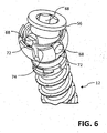
- FIG. 6 an alternative mounting of the insert 54 is shown on the screw head 16.
- the insert 54 is pivotally mounted via an (additional) gimbal 74 on the screw head 16 of the bone screw 12.
- the insert 54 is arranged with its two first bearing pin 68 held in upwardly open sowandaus strictly adopted 72 of the gimbal 74.
- the gimbal 74 in turn has a pair of second bearing journals 68 which extend into the side wall recesses 72 of the screw head 16 of the bone screw 10.
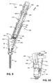
- FIGS. 7 and 8 is a bone screw system 100 with a bone screw 10 explained above and with a reduction instrument 102 for introducing and fixing a fixation rod 104 in the rod receptacle 28 (FIG. Fig. 4 ) of the head housing 18 of the bone screw 10.
- the reduction instrument 102 has a guide sleeve 106 with a through- bore 108 which extends along the instrument longitudinal axis 110 of the reduction instrument 102.
- the guide sleeve 106 is provided with a wall profile 112 , which extends along the instrument longitudinal axis 110 of the guide sleeve 106 away.
- the wall profile 112 has at its free end 114 second coupling means 116 which are complementary to the first coupling means 38 of the first wall portion 30 of the head housing 18.
- the reduction instrument 102 is coupled with the second coupling means 116 of the wall profile 112 to the first coupling means 38 of the head housing 18 of the bone screw 10.
- the second coupling means 116 allow a tensile axial connection between the reduction instrument 102 and the head housing 18th
- the second coupling means 116 are substantially hook-shaped and, in the illustrated coupling position of the reduction instrument 102, engage behind the head housing 18 of the bone screw 10 the first coupling means 38 of the first wall leg 30 of the head housing 18 in a radial and in an axial direction.
- the reduction instrument 102 is thus suspended in the coupling position shown in the two first coupling means 38 of the first wall portion 32 of the head housing 18.
- the reduction instrument 102 can be pivoted relative to the housing longitudinal axis 20 of the head housing 18 in a pivoting direction 118 into its functional position, explained below, on the head housing 18.
- the first coupling means 38 of the head housing 18 serve the reduction instrument 10 when performing the pivoting movement as an abutment or as a pivot point.
- a locking sleeve 120 is arranged, which surrounds the guide sleeve 106 on the outside (completely).
- the locking sleeve 120 serves to lock the reduction instrument 102 on the head housing 18 in its predetermined functional position.
- the locking sleeve 120 is disposed relative to the guide sleeve 106 between a reproduced release position and a locking position on the guide sleeve 106 axially displaceable. This is in Fig. 7 illustrated by the double arrow.
- the locking sleeve 120 has a locking arm 122 .
- the locking arm extends - in a manner corresponding to the wall profile 112 of the guide sleeve 106 - away from the locking sleeve 120 in the axial direction.
- the locking arm 122 engages in the functional position of the reduction instrument 102 on the head housing 18 and arranged in its locking position locking sleeve 120 in the Fig. 3 shown groove-shaped locking recess 50 of the first wall profile 30 of the head housing 18 a.
- the guide sleeve 106 may, as shown in FIG Fig. 7 is shown, on its the locking arm 122 opposite peripheral portion having a locking extension 124 .
- the locking extension extends parallel to the locking arm of the locking sleeve 120 in the axial direction.
- a rotary knob or rotary tool 126 is mounted on the guide sleeve 106.
- the turning tool 126 has at one end a drive profile 126a for the engagement of a wrench or the like.
- the turning tool can, as in the in Fig. 7 embodiment shown is the case, hineinerarranged in the through hole 108 of the guide sleeve 106 at least in sections.
- the rotary tool 126 is rotatably adjustable along the instrument longitudinal axis 110 relative to the guide sleeve 106. In the embodiment shown, the rotary tool 126 is axially fixed in position on the guide sleeve 106.
- the axially non-displaceable setting of the rotary tool 126 on the guide sleeve 106 serve engage two locking pins 127, which pass through the guide sleeve in the radial direction and their ends into an annular groove (not shown) of the rotary tool 126th
- the rotary tool 126 is designed as a hollow cylinder.
- the locking sleeve 120 has a guide pin 128 .
- the guide pin 128 protrudes on the inside in the radial direction away from the locking sleeve 120 and engages in a longitudinal section 130 of a guide groove 132 of the guide sleeve 106 a.
- the locking sleeve 120 is guided over the guide pin on the guide sleeve and rotatably connected in the region of the longitudinal portion 130 of the guide 132.
- the longitudinal portion 130 of the guide groove 132 is connected to a second longitudinal portion (not shown) of the guide groove 132 via a circumferential groove portion 134 .
- the second longitudinal portion of the guide groove 132 is formed open toward the lower end (not shown) of the guide sleeve 106 in order to insert the guide pin 128 into the guide groove 132 when threading (pushing) the locking sleeve 120 onto the guide sleeve 106 during assembly of the reduction instrument 102 or to remove the locking sleeve 120 from the guide sleeve 106 during disassembly of the reduction instrument.
- a bone screw system 100 is shown in longitudinal section, which is essentially in the FIGS. 7 and 8 shown Bone screw system corresponds.
- the locking sleeve 120 is held biased by a supported on the guide sleeve 106 spring member 136 in its locked position.
- the pressure member 142 is axially adjustable by this thread pairing by means of a directed about the instrument longitudinal axis 110 screwing the rotary tool 126 relative to the guide sleeve.
- the rotary tool 126 is thus functionally designed as a movement nut.
- the pressure member 142 also has a tool passage (through hole) 138.
- the pressure member has at one end two tongue-shaped extensions 146 , of which in Fig. 9 for purposes of illustration, only a tongue-shaped extension 146 is shown.
- the two extensions 146 are arranged at a distance from each other and aligned with each other substantially parallel or parallel.
- the two extensions each have a concave contact surface 148 for the fixing rod 104.
- the abutment surfaces 148 can also be embodied in other ways, for example, flat.
- the pressure member has a spring ring 150 , which serves as a holding means for the fixing screw 152 .
- the fixing 152 is held in the spring ring 150 held in a clamping fit and releasably held by this on the reduction tool 102.
- the spring ring 150 is axially secured in position in an annular groove (not shown) of the pressure member 142 on the pressure member 142.
- Fig. 10 shows the bone screw 10 with the reduction instrument 102 coupled thereto in a partially enlarged view.
- the guide sleeve 106 has a lateral wall projection 154 , which is provided with a guide recess 156 for the locking arm 122. Of the Locking arm 122 extends through the guide recess 156 and is slidably guided therein.
- Fig. 11 is the reduction instrument 102 from the in Fig. 12 shown coupling position relative to the head housing 18 in the direction of the head housing longitudinal axis or its functional position pivoted.
- the reduction tool 102 and the head housing 18 of the bone screw are arranged almost in alignment with one another in the direction of the instrument longitudinal axis.
- the locking sleeve 120 has been manually displaced (retracted) axially in the direction of the rotary tool 126 relative to the guide sleeve and is disposed in its release position. In the release position, a pivoting of the reduction instrument 102 relative to the head housing 18 of the bone screw 10 in and out of the in Fig. 13 shown functional position of the reduction instrument 102 allows.
- the fixing rod 104 was moved by the pivoting of the reduction instrument by means of the wall profile 112 of the guide sleeve in the direction of the second wall leg 32 of the head housing 18 (levered).
- the fixing rod bears against the wall profile 112 of the reduction instrument 102 and is arranged in sections between the second wall leg 32 and the wall profile 112 of the reduction instrument 102.
- FIG. 12 the head housing 18 and the lower end of the reduction instrument 102 is shown in a partially enlarged view.
- the second wall leg 32 of the head housing 18 has presently in contrast to that in the FIGS. 7 and 8 shown bone screw in addition to a second locking recess 51 for the locking extension 124 of the locking sleeve 120.
- the locking projection 124 of the reduction instrument 102 in contrast to the instrument according to FIG FIGS. 7 and 8 a locking pin 124a extending inwardly from the locking projection 124 in the radial direction.
- the locking pin 124a is to designed to engage in the locking position of the locked on the head housing 18 locking sleeve 120 in the locking recess 51 of the second wall leg 32.
- FIGS. 13 to 16 is the reduction tool 102 according to Fig. 9 locked to the head housing of the bone screw 10 in its functional position.
- the locking sleeve 120 is arranged in the locking position and engages over the first and the second wall legs 30, 32 of the head housing 18 on the circumference (from the outside).
- the guide sleeve 106 of the reduction instrument 102 is rotatably coupled to the head housing 18 of the bone screw 10 and axially immovably.
- the locking pin 124a engages in the locking recess 51 of the second wall leg 32 a.
- the bone screw system 102 is shown in another operating condition.
- the pressure member 142 was adjusted by rotating the rotary tool 126 about the instrument longitudinal axis 110 axially in the direction of the head housing 18.
- the fixing rod 104 is located, as in particular in Fig. 18 is shown on the two curved abutment surfaces 148 of the tongue-like projections 146 of the pressure member 142 and is positioned in the rod receptacle 28 of the head housing 18.
- the fixing screw 152 is in this operating state of the reduction tool 102 without contact with the fixing rod 104.
- the fixing screw 152 is disposed immediately adjacent to the two internal thread segments 34 of the wall legs 30, 32 of the head housing in the axial direction and can be screwed therein without effort.
- a rod-shaped screwdriver 158 is used, in the FIGS. 20 and 21 is reproduced.
- the screwdriver 158 is inserted into the through holes of the rotary tool and the pressure member.
- the screwdriver 158 has at one end a screw-driving profile 162 aligned with the drive profile 160 of the fixing screw 152, here so-called crown profile (for example, a Torx profile) on.
- the screw driving profile 162 is inserted into the drive profile 160 of the fixing screw.
- the fixing screw 152 was screwed by means of the screwdriver 158 in the internal thread segments 34 of the two wall legs 30, 32 to its fixing position shown.
- the fixing rod 104 In the fixing position, the fixing rod 104 is held clamped in the rod receptacle 28 of the head housing 18 between the fixing screw 152 and the screw head 16.
- the screwdriver 158 has at the other end a square profile for the approach of a wrench or the like. On. It is understood that the screwdriver 158 may also have a different drive and / or driving profile 160, 162.
- the head housing 18 is fixed to the screw head 16 of the bone screw 10. That the head housing 18 is arranged on the screw head 16 held in a clamping fit.
- the reduction instrument 102 is coupled to the first wall limb 30 of the head housing 18, so that the first coupling means 38 of the wall limb 30 and the second coupling means 116 of the reduction instrument 102 are interlocked or interlocked.
- the reduction instrument 102 is subsequently opposite the head housing 18 until it reaches the functional position (FIG. FIGS. 13 to 21 ) of the reduction tool 102 is pivoted.
- the fixing rod 104 is thereby using the wall profile 112 of the reduction tool 102 without additional tools in the radial direction on the second wall leg 32 of the head housing 18 of the bone screw 10 is moved or levered.
- the locking sleeve 120 is before reaching the functional position of the reduction tool relative to the head housing 18 manually and against the force of the spring element 136 in the axial direction in its release position ( FIGS. 11, 12 ) drawn. After reaching the functional position of the reduction tool 102, the locking sleeve 120 is released, so that it is automatically transferred by the force of the spring element 136 in the axial direction relative to the guide sleeve 106 in its locked position. The reduction tool 102 is locked by the locking sleeve in its functional position on the head housing 18 of the bone screw 10.
- the fixation rod 104 is captured between the wall profile 112 of the reduction instrument 102 and the (long) second wall leg 32 of the head housing 18.
- the rotary tool 126 is rotated manually or by means of a force acting on the drive profile of the rotary tool further tool relative to the guide sleeve 116 (manually).
- the pressure member 142 is thereby adjusted relative to the guide sleeve 116 in the axial direction.
- the fixing rod 104 is pushed by the pressure member 142 in the axial direction on and against the screw head 16 or its insert part 54 (FIG. Fig. 4 ).
- the screwdriver 158 is inserted into the reduction tool 102 in the axial direction.
- the fixing screw and the internal thread segments 34 of the wall legs 30, 32 are brought into a mutual threaded engagement under a gentle axial-directional pressure and by turning the screwdriver.
- the fixing screw 152 engages in the internally threaded segments 34 of the rod receptacle 28, the fixing screw 152, preferably with a defined torque, is screwed into the internally threaded segments 34.
- the fixing rod 104 is fixed by a corresponding tightening torque of the fixing screw 152 in the rod receptacle 28 and so the head housing 18 at the same time clamped in its optimal position relative to the longitudinal axis 22 of the bone screw 18 on the screw head 16 (fixed).
- the screwdriver 158 is pulled out of the reduction tool 102.
- the pressure member 142 is rotated by rotating the rotary tool Instrument longitudinal axis 110 moved back in the axial direction of the fixing rod.
- the locking sleeve 120 can be transferred to its release position.
- the reduction tool 102 can subsequently from its functional position on the head housing relative to the head housing 18 in the Ankoppelwolf ( Fig. 7 ) are pivoted back and disconnected from the head housing 18.
- the second wall leg of the head housing is subsequently shortened to the length L1 of the first wall leg. This can be done, for example, by breaking off the free end section of the wall limb in the region of the predetermined breaking point 44 of the second wall limb.
Landscapes
- Health & Medical Sciences (AREA)
- Orthopedic Medicine & Surgery (AREA)
- Neurology (AREA)
- Life Sciences & Earth Sciences (AREA)
- Surgery (AREA)
- Heart & Thoracic Surgery (AREA)
- Engineering & Computer Science (AREA)
- Biomedical Technology (AREA)
- Nuclear Medicine, Radiotherapy & Molecular Imaging (AREA)
- Medical Informatics (AREA)
- Molecular Biology (AREA)
- Animal Behavior & Ethology (AREA)
- General Health & Medical Sciences (AREA)
- Public Health (AREA)
- Veterinary Medicine (AREA)
- Surgical Instruments (AREA)
Description
- Die Erfindung betrifft ein Knochenschraubensystem mit einer Knochenschraube und mit einem Repositionsinstrument.
- Bei der operativen Instrumentierung der Wirbelsäule werden in der klinischen Praxis Knochenschrauben mit einem am Schraubenkopf befestigten Kopfgehäuse eingesetzt. Das Kopfgehäuse weist eine Stabaufnahme für einen Fixierstab auf, der einem Aufrichten und/oder gegenseitigen Stabilisieren bzw. Führen von Wirbelkörpern dient.
- Die Kopfgehäuse sind üblicher Weise als sogenannte Tulpenköpfe ausgebildet. Bei den sogenannten monoaxialen Knochenschrauben sind die Kopfgehäuse am Schraubenkopf drehfest oder einachsig verdrehbar angeordnet. Bei den sogenannten polyaxialen Knochenschrauben können die Kopfgehäuse gegenüber der Längsachse des Gewindeschafts ein- oder mehrachsig ausgelenkt werden.
- Bei einer langstreckigen offenen Instrumentierung der Wirbelsäule (="Mehretageninstrumentierung"), wie diese beispielsweise bei Operationen zur Korrektur von Wirbelsäulendeformitäten, insbesondere einer Skoliose, erforderlich ist, muss der eingesetzte Fixierstab in der Stabaufnahmen einer Vielzahl von Knochenschrauben positioniert und fixiert werden. Die in der Praxis eingesetzten Fixierstäbe sind in der Regel äußerst biegesteif und werden bevorzugt außerhalb des Körpers in eine gewünschte Form vorgebogen. Sobald der Fixierstab in der Stabaufnahme einer anderen Knochenschraube gehalten angeordnet ist, kann dieser deshalb oftmals nur unter hohem Aufwand, beispielsweise mittels eines sogenannten "rod-benders", nachträglich in Form gebogen bzw. in die Stabaufnahme herkömmlicher Lang-Kopfgehäuse eingebracht werden. Dazu muss der Fixierstab in der Regel über einen der beiden Wandschenkel des Kopfgehäuses (hinweg-)gehebelt werden. In der Praxis kommt es dadurch häufig zu einer übermäßigen Gewebstraumatisierung, die u.a. Wundinfektion Vorschub leisten kann.
-
US 2002/013585 A1 offenbart beispielsweise ein Knochenschraubensystem mit einem Repositionsinstrument und mit einer Knochenschraube für Implantate zur Korrektur und Stabilisierung der Wirbelsäule. Die Knochenschraube weist einen Gewindeschaft mit einem Schraubenkopf mit einem Antriebsprofil auf. Ein Kopfgehäuse ist über einen Kopplungsabschnitt mit dem Schraubenkopf verbunden. Das Kopfgehäuse weist eine Stabaufnahme für einen Fixierstab auf, die von einem ersten und einem zweiten Wandschenkel seitlich begrenzt ist, die sich in Richtung einer Gehäuselängsachse vom Kopplungsabschnitt wegerstrecken. Die beiden Wandschenkel weisen jeweils ein Innengewindesegment für eine Fixierschraube auf, mittels derer der Fixierstab in der Stabaufnahme festlegbar ist. Der zweite Wandschenkel überragt den ersten Wandschenkel in axialer Richtung. Der erste Wandschenkel weist an seinem freien Randabschnitt ein erstes Kopplungsmittel zum Ankoppeln des Repositionsinstruments auf. Der zweite Wandschenkel des Kopfgehäuses ist mit einer Sollbruchstelle versehen, die axial auf Höhe oder im Wesentlichen auf Höhe des freien Endes des ersten Wandschenkels angeordnet ist. -
US 2003/225408 A1 offenbart ein weiteres Knochenschraubensystem mit einer Knochenschraube und mit einem Repositionsinstrument zum Einbringen und Fixieren eines Fixierstabs in der Stabaufnahme des Kopfgehäuses der Knochenschraube. Das Repositionsinstrument weist eine Führungshülse mit einer längsaxialen Durchgangsbohrung und mit einem Wandprofil auf, das sich in axialer Richtung von der Führungshülse wegerstreckt. Das Wandprofil weist an seinem freien Ende ein zweites Kopplungsmittel auf, das zu dem ersten Kopplungsmittel desersten Wandschenkels des Kopfgehäuses der Knochenschraube komplementär ausgebildet ist. Ein Arretiermittel dient einem Arretieren der Führungshülse an den beiden Wandschenkeln des Kopfgehäuses. Ein Druckglied zum Absenken des Fixierstabs ist in der Durchgangsbohrung der Führungshülse axial verstellbar angeordnet. Ein Drehwerkzeug ist an der Führungshülse relativ zu dieser drehbar gelagert, wobei das Drehwerkzeug mit dem Druckglied derart gekoppelt ist, dass das Druckglied durch ein Verdrehen des Drehwerkzeugs relativ zur Führungshülse axial verstellbar ist. - Weitere Knochenschraubensysteme mit einer Knochenschraube und einem Repositionsinstrument zum Einbringen und Fixieren eines Fixierstabs in der Stabaufnahme des Kopfgehäuses der Knochenschraube sind aus der
US 2012/0191144 A1 , derUS 2011/0202096 A1 und derUS 2012/0253413 A1 bekannt.US 2009/0270916 A1 offenbart eine Knochenschraube mit unterschiedlich langen Wandschenkeln. Weitere Knochenschrauben sind in derUS 2011/0208248 A1 , derUS 2007/0093827 A1 und derUS 5,733,286 A bekannt. - Aufgabe der Erfindung ist es, ein Knochenschraubensystem mit einer Knochenschraube und mit einem Repositionsinstrument anzugeben, die gegenüber den bekannten Knochenschraubensystemen bei vereinfachter Handhabung eine geringere Gewebetraumatisierung selbst bei minimalinvasiven operativen Zugängen ermöglichen.
- Die das Knochenschraubensystem betreffende Aufgabe wird durch ein Knochenschraubensystem mit den in Patentanspruch 1 angegebenen Merkmalen gelöst.
- Weiterbildungen der Erfindung sind Gegenstand von Unteransprüchen.
- Das erfindungsgemäße Knochenschraubensystem erlaubt nicht zuletzt durch die unterschiedlich langen Wandschenkel der Stabaufnahme des Kopfgehäuses der Knochenschraube ein kraftschonendes, weniger traumatisches und deutlich vereinfachtes Einbringen und Fixieren des Fixierstabs in der Stabaufnahme. Dies insbesondere dann, wenn der Fixierstab bereits an/in anderen Knochenschrauben festgesetzt ist. Erforderliche Operationszeiten können dadurch insgesamt verkürzt und zeitraubende sowie häufig traumatisierende Revisionen an der Instrumentierung vermieden werden. Der längere zweite Wandschenkel des Köpfgehäuses kann nach dem Festlegen bzw. Fixieren des Fixierstabs im Kopfgehäuse mit einfachen Mitteln, beispielsweise einer Zange oder dergl. im Bereich der Sollbruchstelle abgebrochen und so auf ein erforderliches Mindestmaß gekürzt werden. Durch die zum Arretieren des Repositionsinstruments am Kopfgehäuse der Knochenschraube erforderliche Schwenkbewegung des Instruments gegenüber dem Kopfgehäuse kann ein Fixierstab ohne großen Kraftaufwand mit dem Instrument in Richtung auf die Gehäuseachse des Kopfgehäuses geführt (gehebelt) und zwischen dem Wandprofil der Führungshülse des Repositionsinstruments und dem (längeren) zweiten Wandschenkel des Kopfgehäuses gefangen werden. Der Fixierstab kann mittels des Repositionswerkzeugs in der Stabaufnahme des Kopfgehäuses auf einfache und kontrollierte Weise abgesenkt werden. Die Fixierschraube kann nachfolgend in die Gewindesegmente der Stabaufnahme eingeschraubt wird, um den Fixierstab in der Stabaufnahme der Knochenschraube festzusetzen. Durch die Entkopplung des Reponierens bzw. Absenken des Fixierstabs in der Stabaufnahme und des Einschraubens der Fixierschraube mit Hilfe eines Schraubendrehers oder dergl. wird eine besonders einfache, zügige und zugleich sichere Handhabung des Knochenschraubensystems ermöglicht.
- Das Arretiermittel des Repositionswerkzeugs ist im konstruktiv einfachsten Fall als eine Arretierhülse ausgebildet, die die Führungshülse umgreift und die auf der Arretierhülse in axialer Richtung zwischen einer Freigabestellung und einer Arretierstellung relativ zur Führungshülse verstellbar ist. Die Arretierhülse ist dazu ausgebildet, in der ihrer Arretierstellung den ersten Wandschenkel und den zweiten Wandschenkel des Kopfgehäuses der Knochenschraube außenseitig zu über- bzw. zu umgreifen.
- Die Arretierhülse kann erfindungsgemäß einen Arretierarm aufweisen, der sich von der Arretierhülse in axialer Richtung wegerstreckt und der in Arretierstellung der Arretierhülse in eine Arretierausnehmung des ersten Wandschenkels der Knochenschraube eingreift. Dadurch kann einem unerwünschten Abrutschen des Arretierarms von dem ersten Wandschenkel der Stabaufnahme der Knochenschraube zuverlässig entgegengewirkt werden.
- Die Arretierhülse kann zusätzlich einen Arretierfortsatz aufweisen, der an einem dem Arretierarm in radialer Richtung gegenüberliegen Hülsenabschnitt der Arretierhülse angeordnet ist. Der Arretierfortsatz erstreckt sich von der Arretierhülse in axialer Richtung weg und ist zum Arretierarm der Arretierhülse vorzugsweise parallel verlaufen angeordnet. Der Arretierarm ist dazu ausgebildet, das zweite Wandprofil der Knochenschraube in der Arretierstellung der Arretierhülse außenseitig zu übergreifen. Der Arretierfortsatz kann dabei, beispielsweise einen Arretierstift aufweisen, der dazu ausgebildet ist, in eine Arretierausnehmung des zweiten Wandschenkels des Kopfgehäuses der Knochenschraube eingreifen. Insgesamt kann dadurch kann eine mechanisch hoch belastbare Verkopplung des Repositionsinstruments mit dem Kopfgehäuse realisiert werden. Einem unerwünschten Abrutschen des Repositionsinstruments aus seiner mit dem Kopfgehäuse arretierten Funktionsstellung kann zuverlässig entgegengewirkt werden. Dies ist für die Bediensicherheit des Knochenschraubensystems vorteilhaft.
- Die Arretierhülse kann erfindungsgemäß an der Führungshülse drehfest angeordnet sein. Dies kann beispielsweise durch einen Sicherungsstift realisiert sein, der in ein Langloch bzw. eine Führungsnut der Arretier- oder Führungshülse eingreift.
- Zur Armierung bzw. verbesserten Führung des Arretierarms hat es sich als vorteilhaft erwiesen, wenn die Führungshülse eine Führungsausnehmung aufweist, in der der Arretierarm der Arretierhülse verschiebbar geführt ist. Die Führungsausnehmung ist bevorzugt durch einen seitlichen Wandfortsatz der Führungshülse gebildet. Insgesamt kann dadurch einem unerwünschten seitlichen Abrutschen des Arretierarms von dem Kopfgehäuse bzw. einer Überbelastung des Arretierarms in seiner Arretierstellung relativ zum Kopfgehäuse entgegengewirkt werden.
- Die Handhabung des Repositionsinstruments kann dadurch nochmals weiter vereinfacht und sicherer gemacht werden, dass das Arretiermittel an der Führungshülse in Arretierstellung vorgespannt gehalten ist. Die Arretierhülse kann dazu insbesondere mittels einer vorgespannten Druckfeder an der Führungshülse abgestützt sein.
- Das Drehwerkzeug bzw. der Drehknebel des Repositionsinstruments kann im Hinblick auf eine einfache Montage sowie eine vereinfachte Reinigung des Repositionswerkzeugs an der Führungshülse axial lagefixiert sein. Das Drehwerkzeug steht in diesem Fall mit dem Druckglied vorzugsweise in einem lösbaren Gewindeeingriff. D.h. das Druckglied ist vorzugsweise in das Drehwerkzeug eingeschraubt.
- Das Drehwerkzeug und das Druckglied weisen im konstruktiv einfachsten Fall jeweils einen axial verlaufenden Werkzeugdurchgang für einen Schraubendreher zum Einschrauben der Fixierschraube in das Kopfgehäuse der Pedikelschraube auf.
- Für ein sicheres Halten der Fixierschraube kann das Druckglied vorzugsweise mit einer Halteeinrichtung für die Fixierschraube versehen sein. Das Druckglied kann insbesondere ein Federelement, bevorzugt einen Federring, zum Halten der Fixierschraube aufweisen.
- Im Hinblick auf eine besonders einfache und sichere Handhabung des Positionierinstruments hat es sich als vorteilhaft erwiesen, wenn die Führungshülse eine Anschlagfläche für den zweiten Wandabschnitt des Kopfgehäuses aufweist. Die Anschlagfläche kann insbesondere durch eine randseitige Schulter der Führungshülse gebildet sein. Dadurch kann die Funktionsstellung des Repositionswerkzeugs am Kopfgehäuse der Knochenschraube zügiger und sicher aufgefunden werden. Die Funktionsstellung des Repositionsinstruments ist diejenige Ankoppelstellung des Repositionsinstruments an dem Kopfgehäuse der Knochenschraube, in der das Repositionsinstrument an dem Kopfgehäuse mittels des Arretiermittels bzw. der Arretierhülse arretierbar ist.
- Nach der Erfindung kann die Sollbruchstelle des zweiten Wandschenkels des Kopfgehäuses der Knochenschraube zumindest eine umfangsseitige Kerbe des zweiten Wandschenkel umfassen. Für ein besonders atraumatisches Kürzen des zweiten Wandschenkels hat es sich als vorteilhaft erwiesen, wenn der Wandschenkel innen- und außenseitig mit einer solchen Kerbe versehen ist. Die Sollbruchstelle kann auch durch eine anders geartete Materialschwächung des zweiten Wandschenkels erzeugt sein.
- Das Innengewindesegment des ersten Wandschenkels erstreckt sich in axialer Richtung vorteilhaft bis zum freien Ende des ersten Wandschenkels und das Innengewindesegment des zweiten Wandschenkels erstreckt sich vorteilhaft bis zur oder nahe bis zur Sollbruchstelle des zweiten Wandschenkels. Dadurch kann die Fixierschraube zuverlässig und sicher in das Kopfgehäuse eingeschraubt werden. Einer unerwünschten Beschädigung des Innengewindesegments des zweiten Wandschenkels durch das Kürzen des zweiten Wandschenkels kann darüber hinaus zuverlässig entgegengewirkt werden.
- Nach einer bevorzugten Weiterbildung der Erfindung ist das Kopfgehäuse am Schraubenkopf relativ zur Längsachse des Gewindeschafts der Knochenschraube auslenkbar angeordnet und/oder um seine Gehäuselängsachse frei drehbar am Schraubenkopf angeordnet. Dadurch kann das Kopfgehäuse der Knochenschraube vereinfacht relativ zu dem darin festzusetzenden Fixierstab bzw. zu einem nachstehend beschriebenen Repositionswerkzeug ausgerichtet werden.
- Das Antriebsprofil der Knochenschraube kann erfindungsgemäß von einem Einsatzteil gebildet sein, das in einer Lageraufnahme des Schraubenkopfs angeordnet ist, wobei das Einsatzteil mit dem Schraubenkopf in Richtung um die Längsachse des Gewindeschafts der Knochenschraube drehfest verkoppelt ist und wobei das Einsatzteil am Kopfgehäuse geführt gehalten und gemeinsam mit diesem gegenüber der Längsachse des Gewindeschafts auslenkbar ist. Dadurch kann das Antriebsprofil der Knochenschraube unabhängig von einer Auslenkung (einem Verkippen/Abklappen) des Kopfgehäuses gegenüber der Längsachse des Gewindeschafts der Knochenschraube zu jedem Zeitpunkt mit der Gehäuseachse des Kopfgehäuses ausgerichtet ist bzw. mit dieser fluchtet. Ein Drehwerkzeug kann dadurch einfacher, zügiger und sicherer an das Antriebsprofil der Knochenschraube herangeführt und mit diesem drehschlüssig verkoppelt werden. Ein zeitraubendes, traumatisierendes und die Hardware ggf. beschädigendes Aufsuchen eines zum Ankoppeln an das Antriebsprofil geeigneten Ansetzwinkels des Drehwerkzeugs am Schraubenkopf der Knochenschraube entfällt. Einer übermäßigen Traumatisierung des umgebenden Weichteilgewebes kann dadurch selbst bei einem minimalinvasiven operativen Zugangsweg zuverlässig entgegengewirkt werden. Die Knochenschraube kann als Wirbelkörperschraube zum Einschrauben in den Wirbelkörper eines Wirbels bzw. als sogenannte Pedikelschraube ausgeführt sein.
- Das Einsatzteil kann im konstruktiv einfachsten Fall einen (ersten) Lagerzapfen, bevorzugt zwei (erste) Lagerzapfen, aufweisen, der/die sich jeweils in radialer Richtung vom Einsatzteil wegerstreckt bzw. wegerstrecken. Der bzw. die Lagerzapfen greift/greifen dabei bevorzugt jeweils in eine Seitenwandausnehmung der Lageraufnahme des Schraubenkopfs ein. Die Seitenwandausnehmungen können jeweils als nutartige Vertiefungen der Seitenwand oder aber als Wanddurchbrüche ausgebildet sein. Das Einsatzteil kann dadurch nicht nur um eine durch die Lagerzapfen definierte erste Dreh- bzw. Kippachse gegenüber dem Schraubenkopf verkippt werden, sondern auch um eine zu dieser orthogonal ausgerichtete zweite Dreh- bzw. Kippachse in der/denn Seitenwandausnehmung(en) des Schraubenkopfs gegenüber dem Schraubenkopf bzw. der Längsachse des Gewindeschafts der Knochenschraube verkippt werden. Es versteht sich, dass das erfindungsgemäße Einsatzteil mit dem Antriebsprofil auch für den Einsatz bei mehrstückig ausgeführten monoaxialen Knochenschrauben, insbesondere mit einem abgewinkelten Kopfgehäuse, geeignet ist.
- Die Seitenwandausnehmung/-en der Lageraufnahme sind erfindungsgemäß vorzugsweise zum freien Ende des Schraubenkopfs hin offen. Dadurch kann das Einsatzteil vereinfacht am Schraubenkopf montiert werden.
- Nach einer besonders bevorzugten Weiterbildung der Erfindung ist das Einsatzteil an einem in der Lageraufnahme verschwenkbar angeordneten Kardanring gelagert. Der erste bzw. die ersten Lagerzapfen des Einsatzteils greifen dabei bevorzugt in jeweils eine Seitenwandausnehmung des Kardanrings ein. Dadurch kann insgesamt ein nochmals vergrößerter Bewegungsumfang des Einsatzteils bzw. des Kopfgehäuses relativ zur Längsachse des Gewindeschafts der Knochenschraube realisiert werden. Darüber hinaus ergibt sich dadurch eine besonders leichtgängige Lagerung des Einsatzteils am Schraubenkopf. Dies ist für ein in der klinischen Praxis oftmals wesentliches feinfühliges Ausrichten des Kopfgehäuses von Vorteil. Der Kardanring greift vorzugsweise mit zweiten Lagerzapfen in Seitenwandausnehmungen des Schraubenkopfs ein, die zum (kopfseitigen) freien Ende der Knochenschraube hin bevorzugt offen ausgebildet sind. Die Seitenwandausnehmungen können dabei als nutartige Einbuchtungen bzw. Vertiefungen der Seitenwand oder aber als Wanddurchbrüche ausgebildet sein.
- Das Einsatzteil kann nach der Erfindung zumindest abschnittsweise eine sphärische Außenkontur bzw. Außenseite und die Lageraufnahme des Schraubenkopfs zumindest abschnittsweise eine, insbesondere dazu korrespondierend ausgebildete, gewölbte Seitenwand aufweisen. Dies ist für die mechanische Belastbarkeit der Einsatzteil-Schraubenkopfkopplung von Vorteil. Darüber hinaus kann die Lageraufnahme des Schraubenkopfs beim Festsetzen eines Fixierstabs in der Stabaufnahme durch das Einsatzteil in radialer Richtung aufgeweitet und dadurch mit dem Kopfgehäuses verklemmt werden. Im Hinblick auf eine optimierte Klemmwirkung hat es sich als vorteilhaft erwiesen, wenn die Außenkontur bzw. Außenseite des Einsatzteils vielfach facettiert ausgeführt ist. Der Schraubenkopf kann nach der Erfindung darüber hinaus mehrfach geschlitzt sein, um ein gleichmäßiges Aufdehnen (Aufweiten) des Schraubenkopfes zu ermöglichen.
- Das Einsatzteil kann erfindungsgemäß insbesondere mit einem ringbundförmigen Führungsabschnitt am Kopfgehäuse innenseitig anliegen. Dadurch kann das Kopfgehäuse überdies um seine Gehäuselangsachse gegenüber dem Schraubenkopf frei verdreht werden. Unter fertigungstechnischen Gesichtspunkten ist das Einsatzteil vorteilhaft mittels des Kopfgehäuses in der Lageraufnahme des Schraubenkopfs axial lagegesichert.
- Eine besonders einfache Montage eines Kopfgehäuses an einem Schraubenkopf einer Knochenschraube kann erfindungsgemäß dadurch realisiert werden, dass das Kopfgehäuse über einen Federring mit dem Schraubenkopf der Knochenschraube unlösbar verrastet ist. Diese unlösbare Rastverbindung des Kopfgehäuses mit dem Schraubenkopf kann nicht zerstörungsfrei gelöst werden.
- Der Federring ist vorzugsweise geschlitzt ausgeführt und kann nach der Erfindung in radialer Richtung innen- oder außenspannend ausgeführt sein. Auf zusätzliche Sicherungselemente kann dadurch verzichtet werden.
- Im Falle eines innenspannenden Federrings weist das Kopfgehäuse erfindungsgemäß vorzugsweise eine Schraubenkopfaufnahme auf, deren Seitenwand mit einer Ringnut versehen ist. Die Ringnut ermöglicht, dass der Federring bei einem axialen Aufstecken des Kopfgehäuses auf den Schraubenkopf in radialer Richtung ausweichen kann, um eine Passage (insbesondere der Äquatorialebene) des Schraubenkopfs durch den Federring hindurch zu ermöglichen. Innerhalb der Ringnut ist vorteilhaft ein Vorsprung für eine radiale Begrenzung einer Aufweitung des Federrings angeordnet. Der Vorsprung ist dabei vorzugsweise in einem unteren (gewindeschaftseitigen) Bereich der Nut angeordnet. Der Vorsprung kann insbesondere ringförmig umlaufend ausgebildet sein.
- Zur axialen Lagesicherung des Federrings in seiner Sperr- bzw. Raststellung kann das Kopfgehäuse erfindungsgemäß ein Sicherungsmittel, beispielsweise einen Sicherungsstift aufweisen, der sich durch die Wand des Kopfgehäuses hindurcherstreckt und der in die Ringnut des Kopfgehäuses hineinragt.
- Ein unerwünschtes axiales Entfernen bzw. Herausfallen des Federrings aus der Schraubenkopfaufnahme des Kopfgehäuses kann erfindungsgemäß dadurch unterbunden werden, dass die Schraubenkopfaufnahme mit einem axialen Anschlag für den Federring versehen ist. Der Anschlag kann insbesondere durch einen Seitenwandvorsprung, beispielsweise einen Ringbund, eine Nutflanke oder dergl., gebildet sein.
- Nach einer bevorzugten Weiterbildung der Erfindung weist das Kopfgehäuse einen Kopplungsabschnitt mit einer Schraubenkopfaufnahme auf, die eine gewölbte Innenwand aufweist. Die Schraubenkopfaufnahme kann auch konisch ausgeformt sein. Dadurch kann eine (polyaxiale) Anlenkung des Kopfgehäuses an einem sphärischen Schraubenkopf einer Knochenschraube auf einfache Weise realisiert werden. D. h., das Kopfgehäuse kann dadurch am Schraubenkopf relativ zur Längsachse des Gewindeschafts der Knochenschraube ein- oder mehrachsig verkippbar angeordnet werden.
- Weitere Vorteile und vorteilhafte Ausgestaltungen des Gegenstands der Erfindung ergeben sich aus der Beschreibung, den Ansprüchen und der Zeichnung. Ebenso können die vorstehend genannten und die noch weiter aufgeführten Merkmale je für sich oder zu mehreren in beliebigen Kombinationen Verwendung finden.
- Nachfolgend wird die Erfindung anhand eines in der Zeichnung wiedergegebenen Ausführungsbeispiels näher erläutert. Die gezeigte und beschriebene Ausführungsform ist nicht als abschließende Aufzählung zu verstehen, sondern hat vielmehr beispielhaften Charakter für die Schilderung der Erfindung.
- In der Zeichnung zeigen:
- Fig. 1
- eine Knochenschraube mit einem am Schraubenkopf der Knochenschraube polyaxial angelenkten Kopfgehäuse, das eine Stabaufnahme für einen Fixierstab aufweist, wobei die Stabaufnahme von zwei Wandschenkeln mit unterschiedlicher Länge begrenzt ist und wobei einer der beiden Schenkel mit einer Sollbruchstelle versehen ist;
- Fig. 2
- die Knochenschraube aus
Fig. 1 , in einer anderen Seitenansicht; - Fig. 3
- die Knochenschraube aus
Fig. 1 , in einer perspektivischen Ansicht; - Fig. 4
- die Knochenschraube aus
Fig. 1 , in einem Längsschnitt; - Fig. 5
- die Knochenschraube aus
Fig. 1 , in einer ausschnittsweise explodierten Darstellung ihrer Teile; - Fig. 6
- eine Knochenschraube gemäß
Fig. 1 , bei der das Antriebsprofil der Knochenschraube von einem Einsatzteil gebildet ist, das am Schraubenkopf der Knochenschraube kardanisch gelagert ist; - Fig. 7
- ein Knochenschraubensystem mit einer Knochenschraube gemäß
Fig. 1 , mit einem Repositionswerkzeug und mit einem Fixierstab beim Ankoppeln des Repositionsinstruments an die Knochenschraube, in Seitenansicht; - Fig. 8
- das Knochenschraubensystem gemäß
Fig. 7 in einer anderen Seitenansicht; - Fig. 9
- ein Knochenschraubensystem, das zu dem Knochensystem gemäß
Fig. 7 ähnlich ist, in einem Längsschnitt; - Fig. 10
- eine ausschnittsweise detailvergrößerte Ansicht des Knochenschraubensystems aus
Fig. 7 ; - Fig. 11
- das Knochenschraubensystem gemäß
Fig. 9 in einer anderen Betriebsstellung des Repositionswerkzeugs an der Knochenschraube, im Längsschnitt; - Fig. 12
- das Knochenschraubensystem gemäß
Fig.11 in einer ausschnittsweise vergrößerten perspektivischen Ansicht; - Fig. 13
- das Knochenschraubensystem gemäß
Fig. 9 mit einem in seiner Funktionsstellung an der Knochenschraube arretierten Repositionswerkzeug, im Längsschnitt; - Fig. 14
- das Knochenschraubensystem gemäß
Fig. 14 in einer perspektivischen Ansicht; - Fig. 15
- das Knochenschraubensystem gemäß
Fig. 15 in einer ausschnittsweise detailvergrößerten perspektivischen Ansicht; - Fig. 16
- das Knochenschraubensystem gemäß
Fig. 15 in einer anderen ausschnittsweise detailvergrößerten perspektivischen Ansicht; - Fig. 17
- das Knochenschraubensystem gemäß
Fig. 15 in einer anderen Betriebszustand, in dem der Fixierstab in der Stabaufnahme vollständig abgesenkt ist und in axialer Richtung an der Knochenschraube anliegt, in einer perspektivischen Ansicht; - Fig. 18
- einen in
Fig. 17 mit x bezeichneten Bereich des Knochenschraubensystems in einer detailvergrößerten perspektivischen Ansicht; - Fig. 19
- das Knochenschraubensystem gemäß
Fig. 17 in einem vergrößerten Detailausschnitt und im Längsschnitt, - Fig. 20
- das Knochenschraubensystem gemäß
Fig. 17 mit einem in das Repositionsinstrument eingeführten Schraubendreher zum Fixieren des Fixierstabs mittels einer Fixierschraube, im Längsschnitt; und - Fig. 21
- einen in
Fig. 20 mit x gekennzeichneten Ausschnitt des Knochenschraubensystems in einer vergrößerten Schnittdarstellung. - In den
Figuren 1 und 2 ist eine Knochenschraube 10 für Implantate zur Korrektur und Stabilisierung der Wirbelsäule in Seitenansicht gezeigt. Die Knochenschraube 10 ist speziell auf den Gebrauch bei langstreckigen offenen Instrumentierung der Wirbelsäule, insbesondere zur Korrektur von Wirbelsäulendeformitäten, ausgerichtet und kann insbesondere auch bei minimalchirurgische Operationstechniken eingesetzt werden. Die Knochenschraube 10 umfasst einen Gewindeschaft 12 mit einem Gewinde 14, einem Schraubenkopf 16 sowie ein am Schraubenkopf 16 polyaxial angelenktes Tulpen- oder Kopfgehäuse 18. D. h. das Kopfgehäuse 18 kann mit seiner Gehäuselängsachse 20 gegenüber der Längsachse 22 des Gewindeschafts 12 der Knochenschraube 12 (mehrachsig) frei ausgelenkt und vorliegend zusätzlich gegenüber dem Schraubenkopf 16 um die Längsachse 22 des Gewindeschafts 12 der Knochenschraube 10 frei verdreht werden. - Das Kopfgehäuse 18 ist vorliegend gegenüber dem Schraubenkopf 16 in seiner Neutralstellung angeordnet. In Neutralstellung fallen die Gehäuselängsachse 20 und die Längsachse 22 der Knochenschraube 10 zusammen, d.h. das Kopfgehäuse 18 ist gegenüber der Längsachse 22 nicht abgeklappt.
- Das Kopfgehäuse 18 weist einen ringförmigen Kopplungsabschnitt 24 und einen Aufnahmeabschnitt 26 auf. Der Kopplungsabschnitt 24 dient einem Verkoppeln des Kopfgehäuses 18 mit dem Schraubenkopf 16 der Knochenschraube 12. Der Kopplungsabschnitt 26 weist eine in
Fig. 4 näher wiedergegebene Schraubenkopfaufnahme für den Schraubenkopf 16 der Knochenschraube 10 auf. - Der Aufnahmeabschnitt 26 des Kopfgehäuses 18 weist eine Stabaufnahme 28 für einen nicht näher wiedergegebenen Fixierstab auf, wie dieser in der Praxis beispielsweise zur interpedikulären Instrumentierung der Wirbelsäule (Spondylodese) eingesetzt wird.
- Die Stabaufnahme 28 des Kopfgehäuses 18 ist durch einen ersten und einen zweiten Wandschenkel 30, 32 seitlich, d.h. in radialer Richtung zur Gehäuselängsachse 20, begrenzt. Die beiden Wandschenkel 30, 32 sind voneinander beabstandet angeordnet und erstrecken sich parallel zur Gehäuselängsachse 20 vom Kopplungsabschnitt 24 weg. Die Wandschenkel 30, 32 und weisen jeweils ein Innengewindesegment 34 auf, in die eine nicht näher wiedergegebene Fixierschraube eingeschraubt werden kann, um den Fixierstab in der Stabaufnahme des Kopfgehäuses 18 festzusetzen. Die Innengewindesegmente 34 können selbsthemmend ausgebildet sein.
- Der kürzere erste Wandschenkel 30 weist an seinem freien Randabschnitt 36 zwei Kopplungsmittel 38 zum Ankoppeln eines nachstehend erläuterten Repositionsinstruments auf. Die beiden Kopplungsmittel 38 sind beispielhaft jeweils als zungenartige Wandfortsätze ausgebildet, die in Umfangsrichtung zu jeweils einer Seite des kürzeren ersten Wandschenkels 30 angeordnet sind. Die beiden Kopplungsmittel 38 weisen jeweils eine dem Kopplungsabschnitt 24 des Kopfgehäuses 18 zuweisende, hier beispielhaft konvex ausgeführte, Hinterschneidung 40 auf.
- Der längere zweite Wandschenkel 32 steht in Richtung der Gehäuselängsachse 20, d.h. in axialer Richtung, über den ersten Wandschenkel hervor. Eine Länge L2 des zweiten Wandschenkels 32 beträgt ungefähr das 4 fache der Länge L1 des kürzeren ersten Wandschenkels 30. Die Länge L2 des zweiten Wandschenkels 32 kann grundsätzlich das zwei- bis sechsfache der Länge L1 des ersten Wandschenkels 30 betragen.
- Der zweite Wandschenkel 32 weist ungefähr auf axialer Höhe des freien Rands bzw. freien Endes 42 des ersten Wandschenkels eine Sollbruchstelle 44 auf. Die Sollbruchstelle 44 ist durch eine außenseitige Kerbe des zweiten Wandschenkels 32 gebildet. Die Kerbe erstreckt sich in Umfangsrichtung über die gesamte Breite b des zweiten Wandschenkels 32. Die Sollbruchstelle 44 kann auch durch eine innenseitige und eine außenseitige Kerbe oder eine anders geartete Materialschwächung des Materials des zweiten Wandschenkels 32 gebildet sein.
- Das Innengewindesegment 34 des ersten Wandschenkels 30 erstreckt sich in axialer Richtung bis zum freien Ende 42 des ersten Wandschenkels 30. Das Innengewindesegment 34 des zweiten Wandschenkels 32 erstreckt sich bis zur Sollbruchstelle 44.
- Der Gewindeschaft 12 der Knochenschraube 10 kann eine oder mehrere seitliche Ausführungsöffnungen (nicht gezeigt) aufweisen, die das Einbringen von Fremdmaterial in ein den Gewindeschaft 12 umgebendes Knochengewebe erlauben.
- Die Knochenschraube kann grundsätzlich auch als sogenannte monoaxiale Knochenschraube ausgebildet sein.
-
Fig. 3 zeigt die Knochenschraube 10 in einer perspektivischen Ansicht. Das Kopfgehäuse 18 weist eine im Wesentlichen kreiszylindrische Außenmantelfläche 46 auf. Ein Antriebsprofil 48 der Knochenschraube 10 dient dem Angriff eines nicht näher wiedergegebenen Drehwerkzeugs, mit dessen Hilfe die Knochenschraube 10 in den Pedikel oder den Wirbelkörper eines Wirbels (nicht gezeigt) eingedreht bzw. aus diesem wieder herausgedreht werden kann. Das Antriebsprofil 48 ist vorliegend als Innensechskant ausgeführt, kann aber auch andersartig profiliert sein. - Der erste Wandschenkel 30 der Stabaufnahme 28 des Kopfgehäuses weist außenseitig eine mit bezeichnete erste Arretierausnehmung 50 für das nachstehend erläuterte Repositionsinstrument auf. Die erste Arretierausnehmung 50 ist nutförmig ausgebildet und zum freien Ende 42 des ersten Wandschenkel 30 hin offen.
-
Fig. 4 zeigt die Knochenschraube 10 im Längsschnitt. Das Kopfgehäuse 18 ist gegenüber der Längsachse 22 der Knochenschraube 10 abgewinkelt (abgeklappt) angeordnet. - Der Schraubenkopf 16 ist teilweise sphärisch ausgebildet. In einer gewölbten Lageraufnahme 52 des Schraubenkopfs 16 ist ein Einsatzteil 54 angeordnet, das das Antriebsprofil 48 der Knochenschraube 10 bildet. Das Einsatzteil 54 ist mit Schraubenkopf 16 der Knochenschraube 10 drehfest verkoppelt.
- Das Einsatzteil 54 weist einen zu der Lageraufnahme 52 im Wesentlichen korrespondierend ausgeformte kugelförmige Außenseite auf und liegt an einer Seitenwand der Lageraufnahme 52 zumindest abschnittsweise im Gleitspiel-Formschluss an.
- Das Einsatzteil 54 ragt in axialer Richtung aus der Lageraufnahme 52 hervor und erstreckt sich in das Kopfgehäuse 18 hinein. Das Einsatzteil 54 ist mit einem ringbundförmigen Führungsabschnitt 56 in radialer Richtung an dem Kopfgehäuse 18 geführt gehalten.
- Das Kopfgehäuse 18 ist über einen Federring 58 am Schraubenkopf 16 der Knochenschraube 10 axial lagegesichert und unlösbar mit dem Schraubenkopf verrastet. Der Federring 58 umgreift den Schraubenkopf 16 und kann geschlitzt ausgeführt sein. Das Kopfgehäuse 18 ist im Bereich der Schraubenkopfaufnahme 60 des Kopplungsabschnitts 24 innenseitig mit einer Ringnut 62 versehen, die konzentrisch zur Gehäuselängsachse 20 angeordnet ist. Die Ringnut 62 kann auch, insbesondere bei einem abgewinkelt ausgeführten Kopfgehäuse 18 gegenüber der Längsachse 22 verkippt angeordnet sein.
- Der Federring 58 kann bei einem axialen Einführen des Schraubenkopfs 16 in die Schraubenkopfaufnahme 60 des Kopplungsabschnitts 24 durch den Schraubenkopf 16 (auf-)geweitet und dabei in radialer Richtung in die Ringnut 62 hinein ausweichen. Nach einem Passieren der Äquatorialebene des Schraubenkopfs 16 rückt der Federring 58 selbsttätig aus der Ringnut 62 aus. Ein innerhalb der Ringnut 62 angeordneter Vorsprung 64 dient einer radialen Begrenzung einer (erneuten) Aufweitung des Federrings 58. Der Vorsprung 64 ist im unteren Bereich der Ringnut 62 angeordnet. Der Federring 58 fällt bei einer Montage der Knochenschraube 10 und zugleich lotrechter Ausrichtung der Knochenschraube der Schwerkraft folgend axial nach unten (= Fallring) und liegt dann an dem Vorsprung 64 an.
- Der Federring 46 ist durch einen Seitenwandvorsprung 66 des Kopfgehäuses 18 gegenüber einem axialen Entfernen aus der Schraubenkopfaufnahme 64 des Kopfgehäuses 18 gesichert. Das Kopfgehäuse 18 ist damit über den Federring 58 unlösbar mit dem Schraubenkopf 16 verbunden. D.h. die Verbindung des Kopfgehäuses 18 mit dem Schraubenkopf 16 kann nicht zerstörungsfrei gelöst werden.
- Die Knochenschraube kann einen oder mehrere in den
Figuren 1, 2 und4 wiedergegebene Sicherungsstifte 65 aufweisen, die einer axialen Lagesicherung des Federrings 58 am Kopfgehäuse 18 bzw. einer Begrenzung einer Axialbewegung des Federrings relativ zum Kopfgehäuse 18 dienen. - Das Einsatzteil 54 ist geneinsam mit dem Kopfgehäuse gegenüber der Gehäuselängsachse 20 verkippbar und über die Stabaufnahme 28 mit einem Drehwerkzeug (nicht gezeigt) zugänglich.
- Der Gewindeschaft 12 der Knochenschraube 10 ist als Hohlschaft ausgebildet und kann im Bedarfsfall ein Bohrspitze aufweisen.
-
Fig. 5 zeigt den Gewindeschaft 12 und das Einsatzteil 54 der vorstehend beschriebenen Knochenschraube in einer explodierten perspektivischen Ansicht. - Von dem Einsatzteil 54 stehen zwei erste Lagerzapfen 68 seitlich weg, die auf einer gemeinsamen Querachse 70 angeordnet sind. Die Lageraufnahme 52 des Schraubenkopfs 16 weist Seitenwandausnehmungen 72 zur Aufnahme der Lagerzapfen 68 auf. Die Seitenwandausnehmungen 72 sind einenends offen ausgebildet. Nach einem in der Zeichnung nicht näher wiedergegebenen Ausführungsbeispiel können die Seitenwandausnehmungen auch als nutartige Vertiefungen der Seitenwand der Lageraufnahme 52 ausgebildet sein.
- Die beiden ersten Lagerzapfen 68 sind im Montagezustand der Knochenschraube in den Seitenwandausnehmungen 72 angeordnet, so dass das Einsatzteil 54 mit dem Schraubenkopf 16 bezüglich der Längsachse 22 der Knochenschraube 10 drehfest verkoppelt ist.
- In
Fig. 6 ist eine alternative Lagerung des Einsatzteils 54 an dem Schraubenkopf 16 gezeigt. Das Einsatzteil 54 ist über einen (zusätzlichen) Kardanring 74 am Schraubenkopf 16 der Knochenschraube 12 verschwenkbar gelagert. Das Einsatzteil 54 ist mit seinen beiden ersten Lagerzapfen 68 in nach oben hin offenen Seitenwandausnehmungen 72 des Kardanrings 74 gehalten angeordnet. Der Kardanring 74 weist seinerseits ein Paar zweite Lagerzapfen 68 auf, die sich in die Seitenwandausnehmungen 72 des Schraubenkopfes 16 der Knochenschraube 10 hinein erstrecken. - In den
Figuren 7 und 8 ist ein Knochenschraubensystem 100 mit einer vorstehend erläuterten Knochenschraube 10 und mit einem Repositionsinstrument 102 zum Einbringen und Fixieren eines Fixierstabs 104 in der Stabaufnahme 28 (Fig. 4 ) des Kopfgehäuses 18 der Knochenschraube 10 gezeigt. - Das Repositionsinstrument 102 weist eine Führungshülse 106 mit einer Durchgangsbohrung 108 auf, die sich entlang der Instrumentenlängsachse 110 des Repositionsinstruments 102 erstreckt. Die Führungshülse 106 ist mit einem Wandprofil 112 versehen, das sich entlang der Instrumentenlängsachse 110 des von der Führungshülse 106 wegerstreckt. Das Wandprofil 112 weist an seinem freien Ende 114 zweite Kopplungsmittel 116 auf, die zu den ersten Kopplungsmitteln 38 des ersten Wandabschnitts 30 des Kopfgehäuses 18 komplementär ausgebildet sind.
- Das Repositionsinstrument 102 ist vorliegend mit den zweiten Kopplungsmitteln 116 des Wandprofils 112 an die ersten Kopplungsmittel 38 des Kopfgehäuses 18 der Knochenschraube 10 angekoppelt. Die zweiten Kopplungsmittel 116 ermöglichen eine in axialer Richtung zugfeste Verbindung zwischen dem Repositionsinstrument 102 und dem Kopfgehäuse 18.
- Die zweiten Kopplungsmittel 116 sind vorliegend im Wesentlichen hakenförmig ausgeformt und hintergreifen in der gezeigten Ankoppelstellung des Repositionsinstruments 102 an dem Kopfgehäuse 18 der Knochenschraube 10 die ersten Kopplungsmittel 38 des ersten Wandschenkels 30 des Kopfgehäuses 18 in einer radialen und in einer axialen Richtung. Das Repositionsinstrument 102 ist somit in der gezeigten Ankoppelstellung in die beiden ersten Kopplungsmittel 38 des ersten Wandabschnitts 32 des Kopfgehäuses 18 eingehängt. Das Repositionsinstrument 102 kann gegenüber der Gehäuselängsachse 20 des Kopfgehäuses 18 in einer Schwenkrichtung 118 in seine nachstehend erläuterte Funktionsstellung am Kopfgehäuse 18 verschwenkt werden. Die ersten Kopplungsmittel 38 des Kopfgehäuses 18 dienen dem Repositionsinstrument 10 beim Ausführen der Schwenkbewegung dabei als Widerlager bzw. als Angelpunkt.
- Auf der Führungshülse 106 ist eine Arretierhülse 120 angeordnet, die die Führungshülse 106 außenseitig (vollständig) umgreift. Die Arretierhülse 120 dient einem Arretieren des Repositionsinstruments 102 an dem Kopfgehäuse 18 in seiner vorgegebenen Funktionsstellung.
- Die Arretierhülse 120 ist relativ zur Führungshülse 106 zwischen einer hier wiedergegebenen Freigabestellung und einer Arretierstellung auf der Führungshülse 106 axial verschiebbar angeordnet. Dies ist in
Fig 7 durch den Doppelpfeil verdeutlicht. - Die Arretierhülse 120 weist einen Arretierarm 122 auf. Der Arretierarm erstreckt sich - in einer zu dem Wandprofil 112 der Führungshülse 106 entsprechenden Weise - von der Arretierhülse 120 in axialer Richtung weg. Der Arretierarm 122 greift in der Funktionsstellung des Repositionsinstruments 102 am Kopfgehäuse 18 und bei in ihrer Arretierstellung angeordneter Arretierhülse 120 in die in
Fig. 3 gezeigte nutförmige Arretierausnehmung 50 des ersten Wandprofils 30 des Kopfgehäuses 18 ein. - Die Führungshülse 106 kann, wie dies in
Fig. 7 gezeigt ist, an ihrem dem Arretierarm 122 gegenüberliegenden Umfangsabschnitt einen Arretierfortsatz 124 aufweisen. Der Arretierfortsatz erstreckt sich parallel zu dem Arretierarm von der Arretierhülse 120 in axialer Richtung weg. - An der Führungshülse 106 ist ein Drehknebel bzw. Drehwerkzeug 126 gelagert. Das Drehwerkzeug 126 weist einenends ein Antriebsprofil 126a für den Angriff eines Schraubenschlüssels oder dergl. auf. Das Drehwerkzeug kann sich, wie dies bei dem in
Fig. 7 gezeigten Ausführungsbeispiel der Fall ist, in die Durchgangsbohrung 108 der Führungshülse 106 zumindest abschnittsweise hineinerstrecken. Das Drehwerkzeug 126 ist entlang der Instrumentenlängsachse 110 gegenüber der Führungshülse 106 rotatorisch verstellbar. Bei dem gezeigten Ausführungsbeispiel ist das Drehwerkzeug 126 an der Führungshülse 106 axial lagefixiert. Zum axial unverschieblichen Festsetzen des Drehwerkzeugs 126 an der Führungshülse 106 dienen zwei Sicherungsstifte 127, die die Führungshülse in radialer Richtung durchgreifen und deren Enden in eine Ringnut (nicht gezeigt) des Drehwerkzeugs 126 eingreifen. Das Drehwerkzeug 126 ist hohlzylindrisch ausgeführt. - Wie aus
Fig. 8 hervorgeht, weist die Arretierhülse 120 einen Führungsstift 128 auf. Der Führungsstift 128 ragt innenseitig in radialer Richtung von der Arretierhülse 120 weg und greift in einen Längsabschnitt 130 einer Führungsnut 132 der Führungshülse 106 ein. Die Arretierhülse 120 ist über den Führungsstift an der Führungshülse geführt und im Bereich des Längsabschnitts 130 der Führungsnut 132 mit dieser drehfest verbunden. Der Längsabschnitt 130 der Führungsnut 132 ist über einen in Umfangsrichtung verlaufenden Nutabschnitt 134 mit einem zweiten Längsabschnitt (nicht gezeigt) der Führungsnut 132 verbunden. Der zweite Längsabschnitt der Führungsnut 132 ist zu dem in der Figur unteren Ende (nicht gezeigt) der Führungshülse 106 hin offen ausgebildet, um ein Einführen des Führungsstifts 128 in die Führungsnut 132 beim Auffädeln (Aufschieben) der Arretierhülse 120 auf die Führungshülse 106 während des Zusammenbaus des Repositionsinstruments 102 bzw. ein Abziehen der Arretierhülse 120 von der Führungshülse 106 bei der Demontage des Repositionsinstruments zu ermöglichen. - In
Fig. 9 ist ein Knochenschraubensystem 100 im Längsschnitt wiedergegeben, das im Wesentlichen dem in denFiguren 7 und 8 gezeigten Knochenschraubensystem entspricht. Die Arretierhülse 120 ist über ein an der Führungshülse 106 abgestütztes Federelement 136 in ihrer Arretierstellung vorgespannt gehalten. - Das Drehwerkzeug 126 weist einen Werkzeugdurchgang (=Durchgangsbohrung) 138 mit einem Innengewinde 140 auf, in das ein Druckglied 142 mit einem Außengewinde 144 eingreift. Das Druckglied 142 ist durch diese Gewindepaarung mittels einer um die Instrumentenlängsachse 110 gerichteten Schraubbewegung des Drehwerkzeugs 126 gegenüber der Führungshülse axial verstellbar. Das Drehwerkzeug 126 ist somit funktionell als eine Bewegungsmutter ausgebildet. Das Druckglied 142 weist ebenfalls einen Werkzeugdurchgang (Durchgangsbohrung) 138 auf.
- Das Druckglied weist einenends zwei zungenförmige Fortsätze 146 auf, von denen in
Fig. 9 aus Darstellungsgründen nur ein zungenförmiger Fortsatz 146 wiedergegeben ist. Die beiden Fortsätze 146 sind voneinander beabstandet angeordnet und zueinander im Wesentlichen parallel oder parallel verlaufend ausgerichtet. Die beiden Fortsätze weisen jeweils eine konkave Anlagefläche 148 für den Fixierstab 104 auf. Die Anlageflächen 148 können auch in anderer Weise, beispielsweise plan, ausgeführt sein. - Das Druckglied weist einen Federring 150 auf, der als Haltemittel für die Fixierschraube 152 dient. Die Fixierschaube 152 ist im Federring 150 im Klemmsitz gehalten Angeordnet und durch diesen am Repositionswerkzeug 102 lösbar gehalten. Der Federring 150 ist in einer Ringnut (nicht gezeigt) des Druckglieds 142 am Druckglied 142 axial lagegesichert.
-
Fig. 10 zeigt die Knochenschraube 10 mit dem daran angekoppelten Repositionsinstrument 102 in einer ausschnittsweise vergrößerten Darstellung. - Die Führungshülse 106 weist einen seitlichen Wandvorsprung 154 auf, der mit einer Führungsausnehmung 156 für den Arretierarm 122 versehen ist. Der Arretierarm 122 erstreckt sich durch die Führungsausnehmung 156 hindurch und ist darin verschiebbar geführt.
- In
Fig. 11 ist das Repositionsinstrument 102 aus der inFig. 12 gezeigten Ankoppelstellung gegenüber dem Kopfgehäuse 18 in Richtung auf die Kopfgehäuselängsachse bzw. seine Funktionsstellung verschwenkt angeordnet. Das Repositionswerkzeug 102 und das Kopfgehäuse 18 der Knochenschraube sind in Richtung der Instrumentenlängsachse zueinander nahezu fluchtend angeordnet. - Die Arretierhülse 120 wurde manuell axial in Richtung auf das Drehwerkzeug 126 gegenüber der Führungshülse verschoben (zurückgezogen) und ist in ihrer Freigabeposition angeordnet. In der Freigabeposition ist ein Verschwenken des Repositionsinstruments 102 relativ zum Kopfgehäuse 18 der Knochenschraube 10 in die bzw. aus der in
Fig. 13 gezeigten Funktionsstellung des Repositionsinstruments 102 ermöglicht. - Der Fixierstab 104 wurde durch das Verschwenken des Repositionsinstruments mittels des Wandprofils 112 der Führungshülse in Richtung auf den zweiten Wandschenkel 32 des Kopfgehäuses 18 bewegt (gehebelt). Der Fixierstab liegt an dem Wandprofil 112 des Repositionsinstruments 102 an und ist abschnittsweise zwischen dem zweiten Wandschenkel 32 und dem Wandprofil 112 des Repositionsinstruments 102 angeordnet.
- In
Fig. 12 ist das Kopfgehäuse 18 und das untere Ende des Repositionsinstruments 102 in einer ausschnittsweise vergrößerten Darstellung wiedergegeben. Der zweite Wandschenkel 32 des Kopfgehäuses 18 weist vorliegend im Gegensatz zu dem in denFiguren 7 und 8 gezeigten Knochenschraube zusätzlich eine zweite Arretierausnehmung 51 für den Arretierfortsatz 124 der Arretierhülse 120 auf. Der Arretierfortsatz 124 des Repositionsinstruments 102 weist im Gegensatz zu dem Instrument gemäßFign. 7 und 8 einen Arretierstift 124a auf, der sich von dem Arretierfortsatz 124 in radialer Richtung nach innen wegerstreckt. Der Arretierstift 124a ist dazu ausgebildet, in der Arretierstellung der am Kopfgehäuse 18 arretierten Arretierhülse 120 in die Arretierausnehmung 51 des zweiten Wandschenkels 32 einzugreifen. - In den
Figuren 13 bis 16 ist das Repositionswerkzeug 102 gemäßFig. 9 am Kopfgehäuse der Knochenschraube 10 in seiner Funktionsstellung arretiert. Die Arretierhülse 120 ist in Arretierstellung angeordnet und übergreift den ersten und den zweiten Wandschenkel 30, 32 des Kopfgehäuses 18 umfangsseitig (von außen). Die Führungshülse 106 des Repositionsinstruments 102 ist an dem Kopfgehäuse 18 der Knochenschraube 10 drehfest und axial unverschieblich angekoppelt. Der Arretierstift 124a greift in die Arretierausnehmung 51 des zweiten Wandschenkels 32 ein. - In den
Figuren 17 bis 19 ist das Knochenschraubensystem 102 in einem weiteren Betriebszustand gezeigt. Das Druckglied 142 wurde durch Verdrehen des Drehwerkzeugs 126 um die Instrumentenlängsachse 110 axial in Richtung auf das Kopfgehäuse 18 verstellt. Der Fixierstab 104 liegt, wie dies insbesondere inFig. 18 gezeigt ist, an den beiden gewölbten Anlageflächen 148 der zungenartigen Fortsätze 146 des Druckglieds 142 an und ist in der Stabaufnahme 28 des Kopfgehäuses 18 positioniert. - Aus der ausschnittsweisen Schnittdarstellung in
Fig. 19 geht hervor, dass die Fixierschraube 152 in diesem Betriebszustand des Repositionswerkzeugs 102 ohne Kontakt zu dem Fixierstab 104 ist. Die Fixierschraube 152 ist zu den beiden Innengewindesegmenten 34 der Wandschenkel 30, 32 des Kopfgehäuses in axialer Richtung unmittelbar benachbart angeordnet und kann darin ohne Kraftsaufwand eingeschraubt werden. - Hierzu wird ein stangenförmiger Schraubendreher 158 eingesetzt, der in den
Figuren 20 und 21 wiedergegeben ist. Der Schraubendreher 158 ist in die Durchgangsbohrungen des Drehwerkzeug und des Druckglieds eingeführt. Der Schraubendreher 158 weist einenends eine auf das Antriebsprofil 160 der Fixierschraube 152 ausgerichtetes Schrauben-Mitnahmeprofil 162, hier ein sogenanntes Kronenprofil (beispielsweise ein Torxprofil) auf. Das Schrauben-Mitnahmeprofil 162 ist in das Antriebsprofil 160 der Fixierschraube eingeführt. Die Fixierschraube 152 wurde mit Hilfe des Schraubendrehers 158 in die Innengewindesegmente 34 der beiden Wandschenkel 30, 32 bis zu ihrer gezeigten Fixierstellung eingedreht. In der Fixierstellung ist der Fixierstab 104 in der Stabaufnahme 28 des Kopfgehäuses 18 zwischen der Fixierschraube 152 und dem Schraubenkopf 16 geklemmt gehalten angeordnet. Der Schraubendreher 158 weist anderenends ein Vierkantprofil für den Ansatz eines Schraubenschlüssels oder dergl. auf. Es versteht sich, das der Schraubendreher 158 auch ein anderes Antriebs- und/oder Mitnahmeprofil 160, 162 aufweisen kann. - Das Kopfgehäuse 18 ist am Schraubenkopf 16 der Knochenschraube 10 festgesetzt. D.h. das Kopfgehäuse 18 ist am Schraubenkopf 16 im Klemmsitz gehalten angeordnet.
- Nachfolgend wird die Funktion des Knochenschraubensytems unter Bezugnahme auf die Figuren erläutert:
- Nach einem Einschrauben der Knochenschraube 10 in den Wirbelkörper oder den Pedikel eines Wirbels (nicht gezeigt) wird das Kopfgehäuse 18 derart gegenüber der Längsachse 22 des Gewindeschafts der Knochenschraube 18 verdreht, dass der Fixierstab 104 innenseitig des zweiten Wandschenkels 32 des Kopfgehäuses 18 zu liegen kommt.
- Nachfolgend wird das Repositionsinstrument 102 an den ersten Wandschenkel 30 des Kopfgehäuses 18 angekoppelt bzw. angesetzt, so dass die ersten Kopplungsmittel 38 des Wandschenkels 30 und die zweiten Kopplungsmittel 116 des Repositionsinstruments 102 ineinandergreifen bzw. miteinander verhakt sind. Das Repositionsinstrument 102 wird nachfolgend gegenüber dem Kopfgehäuse 18 bis zum Erreichen der Funktionsstellung (
Fign. 13 bis 21 ) des Repositionswerkzeugs 102 verschwenkt. Der Fixierstab 104 wird dabei mit Hilfe des Wandprofils 112 des Repositionswerkzeugs 102 ohne zusätzliches Werkzeug in radialer Richtung auf den zweiten Wandschenkel 32 des Kopfgehäuses 18 der Knochenschraube 10 zubewegt bzw. gehebelt. Die Arretierhülse 120 wird vor dem Erreichen der Funktionsstellung des Repositionswerkzeugs relativ zum Kopfgehäuse 18 manuell und entgegen der Kraft des Federelements 136 in axialer Richtung in seine Freigabestellung (Fign. 11, 12 ) gezogen. Nach dem Erreichen der Funktionsstellung des Repositionswerkzeugs 102 wird die Arretierhülse 120 freigegeben, so dass diese durch die Kraft des Federelements 136 selbsttätig in axialer Richtung relativ zur Führungshülse 106 in seine Arretierstellung überführt wird. Das Repositionswerkzeug 102 ist durch die Arretierhülse in seiner Funktionsstellung am Kopfgehäuse 18 der Knochenschraube 10 arretiert. Der Fixierstab 104 ist zwischen dem Wandprofil 112 des Repositionsinstruments 102 und dem (langen) zweiten Wandschenkel 32 des Kopfgehäuses 18 gefangen. - Nachfolgend wird das Drehwerkzeug 126 manuell oder mittels eines am Antriebsprofil des Drehwerkzeugs angreifenden weiteren Werkzeugs gegenüber der Führungshülse 116 (händisch) verdreht. Das Druckglied 142 wird dadurch gegenüber der Führungshülse 116 in axialer Richtung verstellt. Der Fixierstab 104 wird durch das Druckglied 142 in axialer Richtung auf und gegen den Schraubenkopf 16 bzw. dessen Einsatzteil 54 (
Fig. 4 ) gedrückt. Nachfolgend wird der Schraubendreher 158 in axialer Richtung in das Repositionswerkzeug 102 eingeführt. Die Fixierschraube und die Innengewindesegmente 34 der Wandschenkel 30, 32 werden unter einem sanftem axialgerichteten Druck und durch Drehen des Schraubendrehers in einen gegenseitigen Gewindeeingriff gebracht. Sobald die Fixierschraube 152 in die Innengewindesegmente 34 der Stabaufnahme 28 eingreift, wird die Fixierschraube 152, vorzugsweise mit einem definierten Drehmoment, in die Innengewindesegmente 34 eingeschraubt. Der Fixierstab 104 wird durch ein entsprechendes Anzugsmoment der Fixierschraube 152 in der Stabaufnahme 28 festgesetzt und so das Kopfgehäuse 18 zugleich in seiner optimalen Stellung relativ zur Längsachse 22 der Knochenschraube 18 am Schraubenkopf 16 festgeklemmt (festgesetzt). Nachfolgend wird der Schraubendreher 158 aus dem Repositionswerkzeug 102 herausgezogen. Das Druckglied 142 wird durch ein Drehen des Drehwerkzeugs um die Instrumentenlängsachse 110 in axialer Richtung von dem Fixierstab zurückbewegt. Nachfolgend kann die Arretierhülse 120 in ihre Freigabestellung überführt werden. Das Repositionswerkzeug 102 kann nachfolgend aus seiner Funktionsstellung am Kopfgehäuse gegenüber dem Kopfgehäuse 18 in die Ankoppelstellung (Fig. 7 ) zurück verschwenkt und vom Kopfgehäuse 18 abgekoppelt werden. Der zweite Wandschenkel des Kopfgehäuses wird nachfolgend auf die Länge L1 des ersten Wandschenkels gekürzt. Dies kann beispielsweise durch Abbrechen des freien Endabschnitts des Wandschenkels im Bereich der Sollbruchstelle 44 des zweiten Wandschenkel erfolgen.
Claims (12)
- Knochenschraubensystem (100) mit- einer Knochenschraube (10) für Implantate zur Korrektur und Stabilisierung der Wirbelsäule, umfassend:- einen Gewindeschaft (12) mit einem Schraubenkopf (16), der ein Antriebsprofil (48) für ein Drehwerkzeug aufweist, und- ein Kopfgehäuse (18), das über einen Kopplungsabschnitt (24) mit dem Schraubenkopf (16) verbunden ist, wobei das Kopfgehäuse (18) eine Stabaufnahme (28) für einen Fixierstab (104) aufweist, die von einem ersten und einem zweiten Wandschenkel (30, 32) seitlich begrenzt ist,
wobei sich die beiden Wandschenkel in Richtung einer Gehäuselängsachse (20) vom Kopplungsabschnitt (24) wegerstrecken;
wobei die beiden Wandschenkel (30, 32) jeweils ein Innengewindesegment (34) für eine Fixierschraube (152) aufweisen, mittels derer der Fixierstab in der Stabaufnahme festlegbar ist,
wobei der zweite Wandschenkel (32) den ersten Wandschenkel (30) in axialer Richtung überragt,
wobei der erste Wandschenkel (30) an seinem freien Randabschnitt (36) ein erstes Kopplungsmittel (38) zum Ankoppeln eines Repositionsinstruments (102) aufweist und
wobei der zweite Wandschenkel (32) eine Sollbruchstelle (44) aufweist, die axial auf Höhe oder im Wesentlichen auf Höhe des freien Endes (42) des ersten Wandschenkels (30) angeordnet ist; und- einem Repositionsinstrument (102) zum Einbringen und Fixieren eines Fixierstabs (104) in der Stabaufnahme (28) des Kopfgehäuses (18) der Knochenschraube (10), wobei das Repositionsinstrument folgendes umfasst:- eine Führungshülse (106) mit einer längsaxialen Durchgangsbohrung (108) und mit einem Wandprofil (112), das sich in axialer Richtung von der Führungshülse (106) wegerstreckt, wobei das Wandprofil (112) an seinem freien Ende ein zweites Kopplungsmittel (116) aufweist, das zu dem ersten Kopplungsmittel (38) des ersten Wandschenkels (30) des Kopfgehäuses (18) der Knochenschraube (10) komplementär ausgebildet ist;- ein Arretiermittel (120) zum Arretieren der Führungshülse (106) an den beiden Wandschenkeln (30, 32) des Kopfgehäuses (18);- ein Druckglied (142) zum Absenken des Fixierstabs (104), das in der Durchgangsbohrung (108) der Führungshülse (106) axial verstellbar angeordnet ist und;- ein Drehwerkzeug (126), das an der Führungshülse (106) relativ zur Führungshülse (106) verdrehbar gelagert ist, wobei das Drehwerkzeug (126) mit dem Druckglied (142) derart gekoppelt ist, dass das Druckglied (142) durch ein Verdrehen des Drehwerkzeugs (126) relativ zu der Führungshülse (106) axial verstellbar ist, wobei das Arretiermittel eine Arretierhülse (120) ist, die die Führungshülse (106) umgreift und die in axialer Richtung zwischen einer Freigabestellung und einer Arretierstellung relativ zur Führungshülse (106) verstellbar ist, wobei die Arretierhülse in ihrer Arretierstellung den ersten Wandschenkel (30) und den zweiten Wandschenkel (32) des Kopfgehäuses (18) der Knochenschraube (10) außenseitig übergreift und wobei die Arretierhülse einen Arretierarm (122) aufweist, der sich von der Arretierhülse (120) in axialer Richtung wegerstreckt und der dazu ausgebildet ist, in der Arretierstellung der Arretierhülse (120) in eine Arretierausnehmung (50) des ersten Wandschenkels (30) der Knochenschraube (10) einzugreifen. - Knochenschraubensystem nach Anspruch 1, dadurch gekennzeichnet, dass die Arretierhülse (120) einen Arretierfortsatz (124) aufweist, der sich an einem von dem Arretierarm (122) gegenüberliegen Hülsenabschnitt der Arretierhülse (120) von der Arretierhülse (120) in axialer Richtung wegerstreckt und der dazu ausgebildet ist, das zweite Wandprofil (32) der Knochenschraube (10) in der Arretierstellung der Arretierhülse (120) außenseitig zu übergreifen.
- Knochenschraubensystem nach Anspruch 1 oder 2, dadurch gekennzeichnet, dass die Führungshülse (106) eine Führungsausnehmung (156) aufweist, in der der Arretierarm (122) der Arretierhülse (120) verschiebbar geführt ist.
- Knochenschraubensystem nach einem der vorhergehenden Ansprüche, dadurch gekennzeichnet, dass das Arretiermittel (120) an der Führungshülse (106) in Arretierstellung vorgespannt gehalten ist.
- Knochenschraubensystem nach einem der vorhergehenden Ansprüche, dadurch gekennzeichnet, dass das Drehwerkzeug (126) an der Führungshülse (106) axial lagefixiert ist und mit dem Druckglied (142) in einem lösbaren Gewindeeingriff steht.
- Knochenschraubensystem nach einem der vorhergehenden Ansprüche, dadurch gekennzeichnet, dass das Drehwerkzeug (126) und das Druckglied (142) des Repositionsinstruments (102) jeweils einen Werkzeugdurchgang für einen Schraubendreher (158) zum Einschrauben der Fixierschraube (152) in das Kopfgehäuse (18) der Pedikelschraube (10) aufweist.
- Knochenschraubensystem nach einem der vorhergehenden Ansprüche, dadurch gekennzeichnet, dass das Druckglied (142) des Repositionsinstruments (102) ein Federelement, bevorzugt einen Federring (150), zum Halten der Fixierschraube (152) aufweist.
- Knochenschraubensystem nach einem der vorhergehenden Ansprüche, dadurch gekennzeichnet, dass die Sollbruchstelle (44) des zweiten Wandschenkels (32) der Knochenschraube (10) zumindest eine Kerbe des zweiten Wandschenkels (32) umfasst.
- Knochenschraubensystem nach einem der vorhergehenden Ansprüche, dadurch gekennzeichnet, dass sich das Innengewindesegment (34) des ersten Wandschenkels (30) der Knochenschraube (10) in axialer Richtung bis zum freien Ende (42) des ersten Wandschenkels (30) und dass sich das Innengewindesegment (34) des zweiten Wandschenkel (32) bis zu der Sollbruchstelle (44) erstreckt.
- Knochenschraubensystem nach einem der vorhergehenden Ansprüche, dadurch gekennzeichnet, dass das Kopfgehäuse (18) am Schraubenkopf (16) relativ zur Längsachse (22) des Gewindeschafts (12) der Knochenschraube (10) auslenkbar angeordnet und/oder um seine Gehäuselängsachse (20) frei drehbar am Schraubenkopf (16) angeordnet ist.
- Knochenschraubensystem nach einem der vorhergehenden Ansprüche, dadurch gekennzeichnet, dass das Antriebsprofil (48) von einem Einsatzteil (54) gebildet ist, das in einer Lageraufnahme (52) des Schraubenkopfs (16) angeordnet ist, wobei das Einsatzteil (54) mit dem Schraubenkopf (16) in Richtung um die Längsachse (22) des Gewindeschafts (12) der Knochenschraube (10) drehfest verkoppelt ist und wobei das Einsatzteil (54) am Kopfgehäuse (18) geführt gehalten und gemeinsam mit diesem gegenüber der Längsachse des Gewindeschafts (22) auslenkbar ist.
- Knochenschraubensystem nach einem der vorhergehenden Ansprüche, dadurch gekennzeichnet, dass das Kopfgehäuse (18) über einen, vorzugsweise geschlitzten, Federring (58) mit dem Schraubenkopf (16) verbunden ist, wobei das Kopfgehäuse (18) innenseitig eine Ringnut (62) und innerhalb der Ringnut (62) einen Vorsprung (64) für eine radiale Begrenzung einer Aufweitung des Federrings (58) aufweist.
Applications Claiming Priority (2)
| Application Number | Priority Date | Filing Date | Title |
|---|---|---|---|
| DE102012219630.7A DE102012219630A1 (de) | 2012-10-26 | 2012-10-26 | Knochenschraube, Kopfgehäuse für eine Knochenschraube und Repositionsinstrument |
| PCT/EP2013/072389 WO2014064249A2 (de) | 2012-10-26 | 2013-10-25 | Knochenschraube und knochenschraubensystem |
Publications (2)
| Publication Number | Publication Date |
|---|---|
| EP2911600A2 EP2911600A2 (de) | 2015-09-02 |
| EP2911600B1 true EP2911600B1 (de) | 2017-04-19 |
Family
ID=49488599
Family Applications (2)
| Application Number | Title | Priority Date | Filing Date |
|---|---|---|---|
| EP13783341.4A Active EP2911600B1 (de) | 2012-10-26 | 2013-10-25 | Knochenschraube und knochenschraubensystem |
| EP13783535.1A Active EP2911601B1 (de) | 2012-10-26 | 2013-10-25 | Knochenschraube |
Family Applications After (1)
| Application Number | Title | Priority Date | Filing Date |
|---|---|---|---|
| EP13783535.1A Active EP2911601B1 (de) | 2012-10-26 | 2013-10-25 | Knochenschraube |
Country Status (3)
| Country | Link |
|---|---|
| EP (2) | EP2911600B1 (de) |
| DE (1) | DE102012219630A1 (de) |
| WO (2) | WO2014064253A1 (de) |
Families Citing this family (5)
| Publication number | Priority date | Publication date | Assignee | Title |
|---|---|---|---|---|
| DE102014117175A1 (de) * | 2014-11-24 | 2016-05-25 | Aesculap Ag | Pedikelschraubensystem und Wirbelsäulenstabilisierungssystem |
| DE102015008036A1 (de) | 2015-06-09 | 2016-12-15 | Signus Medizintechnik Gmbh | Pedikelschraube mit Tulpe |
| DE102019116368A1 (de) | 2019-06-17 | 2020-12-17 | Aesculap Ag | Teilweise blockierte Pedikelschraube |
| DE102019116374A1 (de) * | 2019-06-17 | 2020-12-17 | Aesculap Ag | Teilweise blockierte Pedikelschraube II |
| CN120126257B (zh) * | 2025-03-10 | 2026-06-05 | 长城信息股份有限公司 | 一种易装高精度无极调节龙骨框架式机柜及安装方法 |
Family Cites Families (11)
| Publication number | Priority date | Publication date | Assignee | Title |
|---|---|---|---|---|
| US5733286A (en) * | 1997-02-12 | 1998-03-31 | Third Millennium Engineering, Llc | Rod securing polyaxial locking screw and coupling element assembly |
| FR2810874B1 (fr) * | 2000-06-30 | 2002-08-23 | Materiel Orthopedique En Abreg | Implant pour dispositif d'osteosynthese comprenant une partie destinee a l'ancrage osseux et un corps de fixation sur une tige |
| US7278995B2 (en) * | 2002-06-04 | 2007-10-09 | Howmedica Osteonics Corp. | Apparatus for securing a spinal rod system |
| US20060293692A1 (en) * | 2005-06-02 | 2006-12-28 | Whipple Dale E | Instruments and methods for manipulating a spinal fixation element |
| WO2007041702A2 (en) * | 2005-10-04 | 2007-04-12 | Alphaspine, Inc. | Pedicle screw system with provisional locking aspects |
| US8308774B2 (en) * | 2007-02-14 | 2012-11-13 | Pioneer Surgical Technology, Inc. | Spinal rod reducer and cap insertion apparatus |
| ES2546286T3 (es) * | 2007-10-23 | 2015-09-22 | K2M, Inc. | Unidad de tornillo poliaxial |
| US9504494B2 (en) * | 2008-04-28 | 2016-11-29 | DePuy Synthes Products, Inc. | Implants for securing spinal fixation elements |
| US8900240B2 (en) * | 2010-02-12 | 2014-12-02 | Pioneer Surgical Technology, Inc. | Spinal rod and screw securing apparatus and method |
| US20120191144A1 (en) * | 2011-01-26 | 2012-07-26 | Warsaw Orthopedic, Inc | Instrument for reduction of a vertebral rod and method of use |
| DE202011100080U1 (de) * | 2011-04-13 | 2011-08-09 | Humantech Germany Gmbh | Tulpenkopfschraube zur Repositionierung von Wirbelkörpern |
-
2012
- 2012-10-26 DE DE102012219630.7A patent/DE102012219630A1/de not_active Withdrawn
-
2013
- 2013-10-25 EP EP13783341.4A patent/EP2911600B1/de active Active
- 2013-10-25 WO PCT/EP2013/072398 patent/WO2014064253A1/de not_active Ceased
- 2013-10-25 WO PCT/EP2013/072389 patent/WO2014064249A2/de not_active Ceased
- 2013-10-25 EP EP13783535.1A patent/EP2911601B1/de active Active
Also Published As
| Publication number | Publication date |
|---|---|
| EP2911600A2 (de) | 2015-09-02 |
| DE102012219630A1 (de) | 2014-04-30 |
| WO2014064253A1 (de) | 2014-05-01 |
| WO2014064249A3 (de) | 2014-06-26 |
| EP2911601A1 (de) | 2015-09-02 |
| EP2911601B1 (de) | 2016-12-07 |
| WO2014064249A2 (de) | 2014-05-01 |
Similar Documents
| Publication | Publication Date | Title |
|---|---|---|
| EP3117787B1 (de) | Pedikelschraube mit tulpe | |
| EP2692304B1 (de) | Chirurgisches Instrumentarium | |
| EP3454767B1 (de) | Medizintechnisches instrument zur provisorischen fixierung einer polyaxialen pedikelschraube | |
| EP1567073B1 (de) | Vorrichtung zur stabilisierung von knochen | |
| EP2962651B1 (de) | Medizinischer schraubendreher und schaft für den medizinischen schraubendreher | |
| EP2266483B1 (de) | Chirurgische Knochenverankerungsvorrichtung und Wirbelsäulenfixationssystem | |
| EP3023065B1 (de) | Pedikelschraubensystem und wirbelsäulenstabilisierungssystem | |
| EP1392190B1 (de) | Manipulator zur handhabung einer pedikelschraube | |
| DE102005009282A1 (de) | Implantatsystem und Befestigungselement für ein Implantatsystem | |
| DE102004027881A1 (de) | Knochenschraube und Osteosynthesevorrichtung | |
| EP3383291B1 (de) | Medizinisches instrument und medizinisches instrumentarium | |
| WO2011076205A1 (de) | Knochenplattensystem für die osteosynthese | |
| EP2848223B1 (de) | Verbindungselement und wirbelsäulenstabilisierungssystem | |
| WO2014064249A2 (de) | Knochenschraube und knochenschraubensystem | |
| WO2017016717A1 (de) | Osteosynthesevorrichtung | |
| EP3023066B1 (de) | Pedikelschraubensystem und wirbelsäulenstabilisierungssystem | |
| EP3031416B1 (de) | Osteosynthesevorrichtung | |
| DE102020003247A1 (de) | Modulare Osteosynthesevorrichtung für Wirbel | |
| DE202004009073U1 (de) | Knochenschraube und Osteosynthesevorrichtung | |
| DE102023107972B4 (de) | Knochenanker, insbesondere Knochenschraube | |
| DE102016215694B4 (de) | Polyaxiale Pedikelschraube mit Verriegelungseinrichtung | |
| EP4051143A1 (de) | Medizintechnisches entkopplungsinstrument | |
| DE102017120620B4 (de) | Knochenanker und Verlängerungsvorrichtung | |
| DE102014108225A1 (de) | Feststellschraube und chirurgisches Schraubensystem | |
| EP4628036A1 (de) | Hülse für eine implantatschraube und implantatschraube mit einer hülse |
Legal Events
| Date | Code | Title | Description |
|---|---|---|---|
| PUAI | Public reference made under article 153(3) epc to a published international application that has entered the european phase |
Free format text: ORIGINAL CODE: 0009012 |
|
| 17P | Request for examination filed |
Effective date: 20150526 |
|
| AK | Designated contracting states |
Kind code of ref document: A2 Designated state(s): AL AT BE BG CH CY CZ DE DK EE ES FI FR GB GR HR HU IE IS IT LI LT LU LV MC MK MT NL NO PL PT RO RS SE SI SK SM TR |
|
| AX | Request for extension of the european patent |
Extension state: BA ME |
|
| DAX | Request for extension of the european patent (deleted) | ||
| GRAP | Despatch of communication of intention to grant a patent |
Free format text: ORIGINAL CODE: EPIDOSNIGR1 |
|
| RIC1 | Information provided on ipc code assigned before grant |
Ipc: A61B 17/70 20060101AFI20160613BHEP Ipc: A61B 17/86 20060101ALI20160613BHEP Ipc: A61B 90/00 20160101ALI20160613BHEP |
|
| INTG | Intention to grant announced |
Effective date: 20160701 |
|
| GRAJ | Information related to disapproval of communication of intention to grant by the applicant or resumption of examination proceedings by the epo deleted |
Free format text: ORIGINAL CODE: EPIDOSDIGR1 |
|
| GRAJ | Information related to disapproval of communication of intention to grant by the applicant or resumption of examination proceedings by the epo deleted |
Free format text: ORIGINAL CODE: EPIDOSDIGR1 |
|
| INTG | Intention to grant announced |
Effective date: 20160701 |
|
| GRAP | Despatch of communication of intention to grant a patent |
Free format text: ORIGINAL CODE: EPIDOSNIGR1 |
|
| INTC | Intention to grant announced (deleted) | ||
| INTG | Intention to grant announced |
Effective date: 20161115 |
|
| GRAS | Grant fee paid |
Free format text: ORIGINAL CODE: EPIDOSNIGR3 |
|
| GRAA | (expected) grant |
Free format text: ORIGINAL CODE: 0009210 |
|
| AK | Designated contracting states |
Kind code of ref document: B1 Designated state(s): AL AT BE BG CH CY CZ DE DK EE ES FI FR GB GR HR HU IE IS IT LI LT LU LV MC MK MT NL NO PL PT RO RS SE SI SK SM TR |
|
| REG | Reference to a national code |
Ref country code: GB Ref legal event code: FG4D Free format text: NOT ENGLISH |
|
| REG | Reference to a national code |
Ref country code: CH Ref legal event code: EP |
|
| REG | Reference to a national code |
Ref country code: AT Ref legal event code: REF Ref document number: 885168 Country of ref document: AT Kind code of ref document: T Effective date: 20170515 |
|
| REG | Reference to a national code |
Ref country code: IE Ref legal event code: FG4D Free format text: LANGUAGE OF EP DOCUMENT: GERMAN |
|
| REG | Reference to a national code |
Ref country code: DE Ref legal event code: R096 Ref document number: 502013007037 Country of ref document: DE |
|
| REG | Reference to a national code |
Ref country code: NL Ref legal event code: MP Effective date: 20170419 |
|
| REG | Reference to a national code |
Ref country code: LT Ref legal event code: MG4D |
|
| PG25 | Lapsed in a contracting state [announced via postgrant information from national office to epo] |
Ref country code: NL Free format text: LAPSE BECAUSE OF FAILURE TO SUBMIT A TRANSLATION OF THE DESCRIPTION OR TO PAY THE FEE WITHIN THE PRESCRIBED TIME-LIMIT Effective date: 20170419 |
|
| REG | Reference to a national code |
Ref country code: FR Ref legal event code: PLFP Year of fee payment: 5 |
|
| PG25 | Lapsed in a contracting state [announced via postgrant information from national office to epo] |
Ref country code: HR Free format text: LAPSE BECAUSE OF FAILURE TO SUBMIT A TRANSLATION OF THE DESCRIPTION OR TO PAY THE FEE WITHIN THE PRESCRIBED TIME-LIMIT Effective date: 20170419 Ref country code: NO Free format text: LAPSE BECAUSE OF FAILURE TO SUBMIT A TRANSLATION OF THE DESCRIPTION OR TO PAY THE FEE WITHIN THE PRESCRIBED TIME-LIMIT Effective date: 20170719 Ref country code: FI Free format text: LAPSE BECAUSE OF FAILURE TO SUBMIT A TRANSLATION OF THE DESCRIPTION OR TO PAY THE FEE WITHIN THE PRESCRIBED TIME-LIMIT Effective date: 20170419 Ref country code: LT Free format text: LAPSE BECAUSE OF FAILURE TO SUBMIT A TRANSLATION OF THE DESCRIPTION OR TO PAY THE FEE WITHIN THE PRESCRIBED TIME-LIMIT Effective date: 20170419 Ref country code: GR Free format text: LAPSE BECAUSE OF FAILURE TO SUBMIT A TRANSLATION OF THE DESCRIPTION OR TO PAY THE FEE WITHIN THE PRESCRIBED TIME-LIMIT Effective date: 20170720 Ref country code: ES Free format text: LAPSE BECAUSE OF FAILURE TO SUBMIT A TRANSLATION OF THE DESCRIPTION OR TO PAY THE FEE WITHIN THE PRESCRIBED TIME-LIMIT Effective date: 20170419 |
|
| PG25 | Lapsed in a contracting state [announced via postgrant information from national office to epo] |
Ref country code: IS Free format text: LAPSE BECAUSE OF FAILURE TO SUBMIT A TRANSLATION OF THE DESCRIPTION OR TO PAY THE FEE WITHIN THE PRESCRIBED TIME-LIMIT Effective date: 20170819 Ref country code: PL Free format text: LAPSE BECAUSE OF FAILURE TO SUBMIT A TRANSLATION OF THE DESCRIPTION OR TO PAY THE FEE WITHIN THE PRESCRIBED TIME-LIMIT Effective date: 20170419 Ref country code: LV Free format text: LAPSE BECAUSE OF FAILURE TO SUBMIT A TRANSLATION OF THE DESCRIPTION OR TO PAY THE FEE WITHIN THE PRESCRIBED TIME-LIMIT Effective date: 20170419 Ref country code: SE Free format text: LAPSE BECAUSE OF FAILURE TO SUBMIT A TRANSLATION OF THE DESCRIPTION OR TO PAY THE FEE WITHIN THE PRESCRIBED TIME-LIMIT Effective date: 20170419 Ref country code: RS Free format text: LAPSE BECAUSE OF FAILURE TO SUBMIT A TRANSLATION OF THE DESCRIPTION OR TO PAY THE FEE WITHIN THE PRESCRIBED TIME-LIMIT Effective date: 20170419 Ref country code: BG Free format text: LAPSE BECAUSE OF FAILURE TO SUBMIT A TRANSLATION OF THE DESCRIPTION OR TO PAY THE FEE WITHIN THE PRESCRIBED TIME-LIMIT Effective date: 20170719 |
|
| REG | Reference to a national code |
Ref country code: DE Ref legal event code: R097 Ref document number: 502013007037 Country of ref document: DE |
|
| PG25 | Lapsed in a contracting state [announced via postgrant information from national office to epo] |
Ref country code: SK Free format text: LAPSE BECAUSE OF FAILURE TO SUBMIT A TRANSLATION OF THE DESCRIPTION OR TO PAY THE FEE WITHIN THE PRESCRIBED TIME-LIMIT Effective date: 20170419 Ref country code: CZ Free format text: LAPSE BECAUSE OF FAILURE TO SUBMIT A TRANSLATION OF THE DESCRIPTION OR TO PAY THE FEE WITHIN THE PRESCRIBED TIME-LIMIT Effective date: 20170419 Ref country code: RO Free format text: LAPSE BECAUSE OF FAILURE TO SUBMIT A TRANSLATION OF THE DESCRIPTION OR TO PAY THE FEE WITHIN THE PRESCRIBED TIME-LIMIT Effective date: 20170419 Ref country code: DK Free format text: LAPSE BECAUSE OF FAILURE TO SUBMIT A TRANSLATION OF THE DESCRIPTION OR TO PAY THE FEE WITHIN THE PRESCRIBED TIME-LIMIT Effective date: 20170419 Ref country code: EE Free format text: LAPSE BECAUSE OF FAILURE TO SUBMIT A TRANSLATION OF THE DESCRIPTION OR TO PAY THE FEE WITHIN THE PRESCRIBED TIME-LIMIT Effective date: 20170419 |
|
| PLBE | No opposition filed within time limit |
Free format text: ORIGINAL CODE: 0009261 |
|
| STAA | Information on the status of an ep patent application or granted ep patent |
Free format text: STATUS: NO OPPOSITION FILED WITHIN TIME LIMIT |
|
| PG25 | Lapsed in a contracting state [announced via postgrant information from national office to epo] |
Ref country code: SM Free format text: LAPSE BECAUSE OF FAILURE TO SUBMIT A TRANSLATION OF THE DESCRIPTION OR TO PAY THE FEE WITHIN THE PRESCRIBED TIME-LIMIT Effective date: 20170419 |
|
| 26N | No opposition filed |
Effective date: 20180122 |
|
| PG25 | Lapsed in a contracting state [announced via postgrant information from national office to epo] |
Ref country code: SI Free format text: LAPSE BECAUSE OF FAILURE TO SUBMIT A TRANSLATION OF THE DESCRIPTION OR TO PAY THE FEE WITHIN THE PRESCRIBED TIME-LIMIT Effective date: 20170419 Ref country code: MC Free format text: LAPSE BECAUSE OF FAILURE TO SUBMIT A TRANSLATION OF THE DESCRIPTION OR TO PAY THE FEE WITHIN THE PRESCRIBED TIME-LIMIT Effective date: 20170419 |
|
| REG | Reference to a national code |
Ref country code: IE Ref legal event code: MM4A |
|
| PG25 | Lapsed in a contracting state [announced via postgrant information from national office to epo] |
Ref country code: LU Free format text: LAPSE BECAUSE OF NON-PAYMENT OF DUE FEES Effective date: 20171025 |
|
| REG | Reference to a national code |
Ref country code: BE Ref legal event code: MM Effective date: 20171031 |
|
| PG25 | Lapsed in a contracting state [announced via postgrant information from national office to epo] |
Ref country code: BE Free format text: LAPSE BECAUSE OF NON-PAYMENT OF DUE FEES Effective date: 20171031 |
|
| PG25 | Lapsed in a contracting state [announced via postgrant information from national office to epo] |
Ref country code: MT Free format text: LAPSE BECAUSE OF FAILURE TO SUBMIT A TRANSLATION OF THE DESCRIPTION OR TO PAY THE FEE WITHIN THE PRESCRIBED TIME-LIMIT Effective date: 20170419 |
|
| REG | Reference to a national code |
Ref country code: FR Ref legal event code: PLFP Year of fee payment: 6 |
|
| PG25 | Lapsed in a contracting state [announced via postgrant information from national office to epo] |
Ref country code: IE Free format text: LAPSE BECAUSE OF NON-PAYMENT OF DUE FEES Effective date: 20171025 |
|
| REG | Reference to a national code |
Ref country code: CH Ref legal event code: NV Representative=s name: RIEDERER HASLER AND PARTNER PATENTANWAELTE AG, LI |
|
| PG25 | Lapsed in a contracting state [announced via postgrant information from national office to epo] |
Ref country code: HU Free format text: LAPSE BECAUSE OF FAILURE TO SUBMIT A TRANSLATION OF THE DESCRIPTION OR TO PAY THE FEE WITHIN THE PRESCRIBED TIME-LIMIT; INVALID AB INITIO Effective date: 20131025 |
|
| PG25 | Lapsed in a contracting state [announced via postgrant information from national office to epo] |
Ref country code: CY Free format text: LAPSE BECAUSE OF FAILURE TO SUBMIT A TRANSLATION OF THE DESCRIPTION OR TO PAY THE FEE WITHIN THE PRESCRIBED TIME-LIMIT Effective date: 20170419 |
|
| PG25 | Lapsed in a contracting state [announced via postgrant information from national office to epo] |
Ref country code: MK Free format text: LAPSE BECAUSE OF FAILURE TO SUBMIT A TRANSLATION OF THE DESCRIPTION OR TO PAY THE FEE WITHIN THE PRESCRIBED TIME-LIMIT Effective date: 20170419 |
|
| PG25 | Lapsed in a contracting state [announced via postgrant information from national office to epo] |
Ref country code: TR Free format text: LAPSE BECAUSE OF FAILURE TO SUBMIT A TRANSLATION OF THE DESCRIPTION OR TO PAY THE FEE WITHIN THE PRESCRIBED TIME-LIMIT Effective date: 20170419 |
|
| PG25 | Lapsed in a contracting state [announced via postgrant information from national office to epo] |
Ref country code: PT Free format text: LAPSE BECAUSE OF FAILURE TO SUBMIT A TRANSLATION OF THE DESCRIPTION OR TO PAY THE FEE WITHIN THE PRESCRIBED TIME-LIMIT Effective date: 20170419 |
|
| PG25 | Lapsed in a contracting state [announced via postgrant information from national office to epo] |
Ref country code: AL Free format text: LAPSE BECAUSE OF FAILURE TO SUBMIT A TRANSLATION OF THE DESCRIPTION OR TO PAY THE FEE WITHIN THE PRESCRIBED TIME-LIMIT Effective date: 20170419 |
|
| REG | Reference to a national code |
Ref country code: CH Ref legal event code: U11 Free format text: ST27 STATUS EVENT CODE: U-0-0-U10-U11 (AS PROVIDED BY THE NATIONAL OFFICE) Effective date: 20251101 |
|
| PGFP | Annual fee paid to national office [announced via postgrant information from national office to epo] |
Ref country code: DE Payment date: 20251022 Year of fee payment: 13 |
|
| PGFP | Annual fee paid to national office [announced via postgrant information from national office to epo] |
Ref country code: GB Payment date: 20251024 Year of fee payment: 13 |
|
| PGFP | Annual fee paid to national office [announced via postgrant information from national office to epo] |
Ref country code: AT Payment date: 20251021 Year of fee payment: 13 |
|
| PGFP | Annual fee paid to national office [announced via postgrant information from national office to epo] |
Ref country code: IT Payment date: 20251031 Year of fee payment: 13 |
|
| PGFP | Annual fee paid to national office [announced via postgrant information from national office to epo] |
Ref country code: FR Payment date: 20251029 Year of fee payment: 13 |
|
| PGFP | Annual fee paid to national office [announced via postgrant information from national office to epo] |
Ref country code: CH Payment date: 20251101 Year of fee payment: 13 |