EP2911358B1 - Method and apparatus for transmitting uplink signal, and method and apparatus for generating uplink signal in communication system - Google Patents
Method and apparatus for transmitting uplink signal, and method and apparatus for generating uplink signal in communication system Download PDFInfo
- Publication number
- EP2911358B1 EP2911358B1 EP15157722.8A EP15157722A EP2911358B1 EP 2911358 B1 EP2911358 B1 EP 2911358B1 EP 15157722 A EP15157722 A EP 15157722A EP 2911358 B1 EP2911358 B1 EP 2911358B1
- Authority
- EP
- European Patent Office
- Prior art keywords
- cyclic shift
- shift value
- sequence
- user
- cyclic
- Prior art date
- Legal status (The legal status is an assumption and is not a legal conclusion. Google has not performed a legal analysis and makes no representation as to the accuracy of the status listed.)
- Active
Links
Images


Classifications
-
- H—ELECTRICITY
- H04—ELECTRIC COMMUNICATION TECHNIQUE
- H04J—MULTIPLEX COMMUNICATION
- H04J11/00—Orthogonal multiplex systems, e.g. using WALSH codes
- H04J11/0023—Interference mitigation or co-ordination
- H04J11/0026—Interference mitigation or co-ordination of multi-user interference
- H04J11/003—Interference mitigation or co-ordination of multi-user interference at the transmitter
-
- H—ELECTRICITY
- H04—ELECTRIC COMMUNICATION TECHNIQUE
- H04L—TRANSMISSION OF DIGITAL INFORMATION, e.g. TELEGRAPHIC COMMUNICATION
- H04L27/00—Modulated-carrier systems
- H04L27/26—Systems using multi-frequency codes
- H04L27/2601—Multicarrier modulation systems
- H04L27/2602—Signal structure
-
- H—ELECTRICITY
- H04—ELECTRIC COMMUNICATION TECHNIQUE
- H04J—MULTIPLEX COMMUNICATION
- H04J11/00—Orthogonal multiplex systems, e.g. using WALSH codes
-
- H—ELECTRICITY
- H04—ELECTRIC COMMUNICATION TECHNIQUE
- H04L—TRANSMISSION OF DIGITAL INFORMATION, e.g. TELEGRAPHIC COMMUNICATION
- H04L1/00—Arrangements for detecting or preventing errors in the information received
- H04L1/12—Arrangements for detecting or preventing errors in the information received by using return channel
- H04L1/16—Arrangements for detecting or preventing errors in the information received by using return channel in which the return channel carries supervisory signals, e.g. repetition request signals
- H04L1/1607—Details of the supervisory signal
- H04L1/1692—Physical properties of the supervisory signal, e.g. acknowledgement by energy bursts
-
- H—ELECTRICITY
- H04—ELECTRIC COMMUNICATION TECHNIQUE
- H04L—TRANSMISSION OF DIGITAL INFORMATION, e.g. TELEGRAPHIC COMMUNICATION
- H04L1/00—Arrangements for detecting or preventing errors in the information received
- H04L1/12—Arrangements for detecting or preventing errors in the information received by using return channel
- H04L1/16—Arrangements for detecting or preventing errors in the information received by using return channel in which the return channel carries supervisory signals, e.g. repetition request signals
- H04L1/18—Automatic repetition systems, e.g. Van Duuren systems
- H04L1/1829—Arrangements specially adapted for the receiver end
- H04L1/1861—Physical mapping arrangements
-
- H—ELECTRICITY
- H04—ELECTRIC COMMUNICATION TECHNIQUE
- H04L—TRANSMISSION OF DIGITAL INFORMATION, e.g. TELEGRAPHIC COMMUNICATION
- H04L1/00—Arrangements for detecting or preventing errors in the information received
- H04L1/12—Arrangements for detecting or preventing errors in the information received by using return channel
- H04L1/16—Arrangements for detecting or preventing errors in the information received by using return channel in which the return channel carries supervisory signals, e.g. repetition request signals
- H04L1/18—Automatic repetition systems, e.g. Van Duuren systems
- H04L1/1867—Arrangements specially adapted for the transmitter end
- H04L1/1887—Scheduling and prioritising arrangements
-
- H—ELECTRICITY
- H04—ELECTRIC COMMUNICATION TECHNIQUE
- H04L—TRANSMISSION OF DIGITAL INFORMATION, e.g. TELEGRAPHIC COMMUNICATION
- H04L25/00—Baseband systems
- H04L25/02—Details ; arrangements for supplying electrical power along data transmission lines
- H04L25/03—Shaping networks in transmitter or receiver, e.g. adaptive shaping networks
- H04L25/03828—Arrangements for spectral shaping; Arrangements for providing signals with specified spectral properties
- H04L25/03866—Arrangements for spectral shaping; Arrangements for providing signals with specified spectral properties using scrambling
-
- H—ELECTRICITY
- H04—ELECTRIC COMMUNICATION TECHNIQUE
- H04L—TRANSMISSION OF DIGITAL INFORMATION, e.g. TELEGRAPHIC COMMUNICATION
- H04L5/00—Arrangements affording multiple use of the transmission path
- H04L5/0001—Arrangements for dividing the transmission path
- H04L5/0003—Two-dimensional division
- H04L5/0005—Time-frequency
- H04L5/0007—Time-frequency the frequencies being orthogonal, e.g. OFDM(A) or DMT
- H04L5/0012—Hopping in multicarrier systems
-
- H—ELECTRICITY
- H04—ELECTRIC COMMUNICATION TECHNIQUE
- H04L—TRANSMISSION OF DIGITAL INFORMATION, e.g. TELEGRAPHIC COMMUNICATION
- H04L5/00—Arrangements affording multiple use of the transmission path
- H04L5/0001—Arrangements for dividing the transmission path
- H04L5/0014—Three-dimensional division
- H04L5/0016—Time-frequency-code
- H04L5/0021—Time-frequency-code in which codes are applied as a frequency-domain sequences, e.g. MC-CDMA
-
- H—ELECTRICITY
- H04—ELECTRIC COMMUNICATION TECHNIQUE
- H04W—WIRELESS COMMUNICATION NETWORKS
- H04W72/00—Local resource management
- H04W72/04—Wireless resource allocation
-
- H—ELECTRICITY
- H04—ELECTRIC COMMUNICATION TECHNIQUE
- H04J—MULTIPLEX COMMUNICATION
- H04J13/00—Code division multiplex systems
- H04J13/0074—Code shifting or hopping
-
- H—ELECTRICITY
- H04—ELECTRIC COMMUNICATION TECHNIQUE
- H04L—TRANSMISSION OF DIGITAL INFORMATION, e.g. TELEGRAPHIC COMMUNICATION
- H04L5/00—Arrangements affording multiple use of the transmission path
- H04L5/003—Arrangements for allocating sub-channels of the transmission path
- H04L5/0048—Allocation of pilot signals, i.e. of signals known to the receiver
-
- H—ELECTRICITY
- H04—ELECTRIC COMMUNICATION TECHNIQUE
- H04L—TRANSMISSION OF DIGITAL INFORMATION, e.g. TELEGRAPHIC COMMUNICATION
- H04L5/00—Arrangements affording multiple use of the transmission path
- H04L5/003—Arrangements for allocating sub-channels of the transmission path
- H04L5/0053—Allocation of signalling, i.e. of overhead other than pilot signals
Definitions
- the present invention relates to a method and an apparatus for transmitting an uplink signal, and a method and an apparatus for generating an uplink signal in a communication system.
- frequency division multiplexing In an orthogonal frequency division multiplexing (OFDM) based communication method, interference does not exist between different users since the different users use different frequencies for data channel.
- a method for using the different frequencies for the different users is referred to as frequency division multiplexing (FDM).
- FDM frequency division multiplexing
- CDM code division multiplexing
- the CDM is superior to the FDM since the CDM can efficiently use resources for the reference signal or the control channel.
- the CDM is classified into a time domain CDM that directly spreads by OFDM symbol units and a frequency domain CDM that spreads in a frequency domain within one OFDM symbol.
- the different users multiply the same sequence by complex sine waves having different phase slopes before transmitting the same sequence.
- a reason why the complex sine wave is used instead of a Hadamard matrix is because orthogonality between the users can be guaranteed through a signal processing at the receiver. Since multiplying any sequence by a complex sine wave with a phase that linearly increases with frequency at the frequency domain is the same as cyclic-shifting in the time domain, a process for multiplying the complex sine wave is referred to as a cyclic-shift process or a cyclic delay process.
- the number of users that can be simultaneously admitted in one OFDM symbol when the frequency domain CDM is used may be given by a function of a frequency difference between subcarriers and delay spread in the propagation channel.
- granularity of the cyclic-shift of each user is set to be greater than a delay spread in the propagation channel.
- the value of the maximum delay spread is arbitrarily set since the maximum delay spread is difficult to be estimated. Accordingly, a channel delay spread of any user may be greater than the cyclic-shift in the cellular communication environment and so, the interference between users may occur.
- US 2006/056360 A1 describes a method and apparatus for code multiplexing one or more control signals onto a shared control channel.
- a control signal for transmission from a base station to a mobile station terminal is repeated in each slot of a predetermined time interval.
- the control signal in each slot is spread using a bit-level spreading sequence, where the bit-level spreading sequence varies from slot to slot according to a predefined sequence-hopping pattern.
- the spread control signals generated for transmission to each mobile station terminal are then combined and spread using a common channelization code.
- the present invention provides a signal transmitting method and apparatus for reducing interference between users in a communication system.
- a method of transmitting an uplink signal in a terminal as defined in claim 1 and a method of receiving anm uplink signal at a base base station as defined in claim 2 are provided.
- the interference between the uses and/or the interference between the cells can be randomized when the frequency domain CDM method is used.
- each block is a unit for processing at least one function or operation, which can be realized by hardware, software, or a combination of hardware and software.
- uplink signal transmitting methods and uplink signal transmitting apparatuses will be described with reference to the drawings. While a system using an OFDM modulation/demodulation is described as an example of a communication system in the exemplary embodiments of the present invention, the present invention can be applicable to various communication systems.
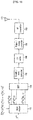
- FIG. 1 shows a schematic block diagram of the uplink signal transmitting apparatus or generating apparatus according to the first exemplary embodiment of the present invention
- FIG. 2 shows a flow diagram of the uplink signal transmitting method or generating method according to the first exemplary embodiment of the present invention.
- the uplink signal transmitting apparatus includes a CDM mapper 110, an inverse fast Fourier transformer (IFFT) 120, a parallel/serial converter 130, a cyclic prefix (CP) adder 140, a digital/analog converter 150, and a radio frequency (RF) transmitter 160.
- CDM mapper 110 an inverse fast Fourier transformer (IFFT) 120
- IFFT inverse fast Fourier transformer
- parallel/serial converter 130 a parallel/serial converter 130
- CP cyclic prefix
- RF radio frequency
- the CDM mapper 110 multiplies a transmission symbol s to be transmitted at a transmission time #n by a sequence c ⁇ i n k for differentiating it from that of another user (i.e., terminal), and allocates the transmission symbol multiplied by the sequence to a frequency bandwidth (step S11). Since the sequence c ⁇ i n k is for identifying the user with a code, the sequence c ⁇ i n k will be referred as a CDM sequence in the exemplary embodiments of the present invention.
- the CDM sequence c ⁇ i n k of which the transmission symbol s ( k ) of the user #k is multiplied may be defined as a vector shown in Equation 1.
- c ⁇ t n k c i n k 0 c i n k 1 ... c i n k N f ⁇ 1 T
- the CDM sequence c ⁇ i n k can be defined as the product of a basic sequence c 0 and the code ⁇ ⁇ i n k for identifying the user as expressed in Equation 2, and the code ⁇ ⁇ i n k for identifying the user will be described as a complex sine wave having a characteristic of a linear phase increase in the exemplary embodiments of the present invention. Multiplying of the complex sine wave in the frequency domain corresponds to shifting in the time domain. Accordingly, the CDM sequence c ⁇ i n k is given by cyclic-shifting the basic sequence c 0 by ⁇ ⁇ i n ( k ) in the time domain.
- ⁇ denotes an operation that multiplies each element of one vector by each element of the other vector
- i n ( k ) denotes a number of the CDM sequence used by the user #k at the transmission time #n
- ⁇ ⁇ denotes a granularity of the cyclic-shift
- N f denotes the number of subcarriers for transmitting the CDM sequence
- the basic sequence c 0 is given as a vector.
- the cyclic-shift is determined based on the number i n ( k ) of the CDM sequence. For example, the cyclic-shift increases by ⁇ ⁇ when the number i n ( k ) of the CDM sequence increases by '1'.
- the IFFT 120 transforms the transmission symbol that is multiplied by the CDM sequence to a transmission signal of the time domain by performing an inverse fast Fourier transform (step S12).
- the parallel/serial converter 130 converts the transmission signal of the time domain to a serial transmission signal (step S13), and the CP adder 140 adds the CP to the serial transmission signal (step S14).
- the digital/analog converter 150 converts the transmission signal to which the CP is added to an analog transmission signal (step S15), and the RF transmitter 160 converts the analog transmission signal to an RF signal and transmits the RF signal through a transmission antenna 170 (step S16).
- the CDM mapper 110 sets a CDM sequence c ⁇ i n + 1 k that is different from the CDM sequence c ⁇ i n k of the transmission time #n to a CDM sequence of a transmission time #(n+1) (step S17), and repeats from the step S11.
- the CDM mapper 110 changes the CDM sequence c ⁇ i n k with time by changing the number i n ( k ) of the CDM sequence c ⁇ i n k with time, that is, by changing a cyclic-shift value for the cyclic-shift with time.
- a pattern for changing the cyclic-shift value may be stored in the terminal in the format of a lookup table.
- channels using the CDM sequence according to the first exemplary embodiment of the present invention may be channels for allocating a plurality of users to the same frequency bandwidth at the same time domain.
- a sounding reference signal or an ACK/NACK channel may use the CDM sequence.
- the sounding reference signal is a wideband signal that is periodically transmitted by the terminal, and is used for estimating the uplink channel characteristic, for controlling the uplink power, and for estimating the timing. Therefore, all users transmit the sounding reference signals by using the same frequency bandwidth at the same time.
- the ACK/NACK channel is a channel for informing whether or not the terminal has received downlink packet data, and is required to have excellent performance at a low signal-to-noise ratio (SNR).
- the CDM sequence according to the exemplary embodiments of the present invention may be applicable to the sounding reference signal and the ACK/NACK channel.
- the transmission symbol s ( k ) is '1' when the CDM sequence is used for the sounding reference signal, and the transmission symbol s ( k ) is an ACK/NACK symbol to be transmitted when the CDM sequence is used for the ACK/NACK channel.
- FIG. 3 shows a schematic block diagram of a receiving apparatus in a base station according to the first exemplary embodiment of the present invention
- FIG. 4 shows a schematic block diagram of a CDM demapper in the receiving apparatus of FIG. 3
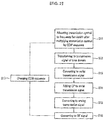
- FIG. 5 shows a flow diagram of a method for extracting a desired user signal
- FIG. 6 shows a signal extracted by the CDM demapper of FIG. 4 .
- the receiving apparatus includes an RF receiver 210, an analog/digital converter 220, a CP remover 230, a serial/parallel converter 240, a fast Fourier transformer (FFT) 250, and a CDM demapper 260.
- the RF receiver 210 receives K user signals from K terminals through a receiving antenna 270, and converts the K user signals to a baseband signal.
- the analog/digital converter 220 converts the baseband signal to a digital received signal.
- the CP remover 230 removes the CP from the digital received signal, and the serial/parallel converter 240 converts the digital received signal from which the CP is removed to a parallel received signal.
- the FFT 250 transforms the parallel received signal to a frequency domain received signal by performing a fast Fourier transform.
- the CDM demapper 260 estimates a vector s k H ⁇ n k from the frequency domain received signal by using the CDM sequence c ⁇ i n k at the transmission time of the user #k (where k is a number within a range from 0 to (K-1)). At this time, the vector is given by a product of the transmission symbol of the user #k and a channel vector.
- the frequency domain received signal X n transformed by the FFT 250 can be expressed as Equation 3.
- ⁇ denotes an operation that multiplies each element of one vector by each element of the other vector
- H n k j denotes a channel value corresponding to the j th subcarrier.
- the CDM demapper 260 includes a basic sequence descrambler 261, an inverse discrete Fourier transformer (IDFT) 262, a time delay domain extractor 263, and a discrete Fourier transformer (DFT) 264.
- IDFT inverse discrete Fourier transformer
- DFT discrete Fourier transformer
- the basic sequence descrambler 261 descrambles the basic sequence by multiplying each element of the frequency domain received signal X n by each element of the conjugated basic sequence c 0 as expressed in Equation 4 (step S21).
- Y ⁇ n X ⁇ n ⁇ c ⁇ o *
- Y n denotes an output of the basic sequence descrambler 261.
- the IDFT 262 transforms the output Y n of the basic sequence descrambler 261 to a time delay domain signal g n by performing an inverse discrete Fourier transform (step S22). It is assumed that 'k' is allocated to the CDM sequence number i n ( k ) of the user #k, and the K user signals are transmitted through the same frequency domain at the same time domain. Then, channel delay profiles of the K user signals appear in the time delay domain signal g n as shown in FIG. 6 , and a time delay between the two adjacent users is ⁇ ⁇ .
- the time delay domain extractor 262 extracts a domain allocated to the user #k at the transmission time #n, and moves data of the extracted domain into an origin to output the time delay domain signal g ⁇ n k of the user #k (step S23).
- the DFT 264 transforms the time delay domain signal g ⁇ n k of the user #k to a desired user signal, i.e., a signal of the user #k, by performing a discrete Fourier transform (step S24).
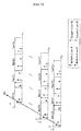
- FIG. 7 shows a time delay domain signal according to the passing of time when a general CDM sequence is used
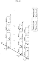
- FIG. 8 shows a time delay domain signal according to the passing of time when the CDM sequence is hopped in accordance with the first exemplary embodiment of the present invention.
- a multipath of a user #0 having the channel delay spread has the effect on an interval of a user #1 such that interference can occur between the users. If the interference occurs in the sounding reference signal, the channel estimation performance of the user #1 deteriorates. Particularly, the channel estimation performance becomes worse when the user #0 has a larger received power than the user #1. In this case, if the same CDM sequence is continuously allocated to the same user even though time is passed, the multipath of the user #0 continuously has the effect on the interval of the user #1 in the time delay domain signals g 0 - g N- 1 such that the channel estimation performance of the user #1 continues to deteriorate.
- the CDM sequence of each user is changed with time such that the users that are adjacent to each other in the time delay domain signals are changed.
- the interference between the users can be randomized. That is, the multipath of the user #0 has the effect on the interval of the user #1 in the time delay domain signal g 0 , but has the effect on the intervals of the user #2 and the user #3 in the time delay domain signals g 1 , and g N -1 , respectively. Accordingly, the channel estimation performance of only one user is not deteriorated by the multipath of the user #0 but the channel estimation performances of the plurality of users can be randomly deteriorated.
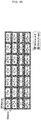
- Table 1 and Table 2 show a CDM sequence allocation method according to the first exemplary embodiment of the present invention.
- Table 1 i 0 i 1 ... i N- 1 User #0 m 0 (0) m 0 (1) ... m 0 ( N- 1)
- User #(K-1) m K -1 (0) m K- 1 (1) m K - 1( N- 1) m K- 1 ( N- 1) m K- 1 ( N- 1)
- i n denotes a CDM sequence number of the transmission time #n
- m k ( n ) denotes the cyclic-shift value that is transmitted by the user #k at the transmission time #n.
- the m k ( n ) has any one of the cyclic-shift values from 0 to (K-1) as expressed in Equation 5.
- ⁇ n , m k n ⁇ 0 , 1 , 2 , ... , K ⁇ 1 , 0 ⁇ k ⁇ K ⁇ 1
- two different users use the different CDM sequences at one time domain.
- the two users use the adjacent CDM sequences at one time domain, the two users use CDM sequences that are not adjacent to each other.
- the base station and the terminal allocate the different cyclic-shift values to the different users at one time domain, hop the cyclic-shift values with time, and allocate the hopped cyclic-shift values to the users. Then, the CDM sequence is hopped with time.
- the hopping pattern of the cyclic-shift is set such that the two users that have used the adjacent cyclic-shift values at one time domain use the cyclic-shift values that are not adjacent to each other at the other time domain.
- the cyclic-shift values of the user #0 and the user #1 are adjacent to each other at the transmission time #0, but the cyclic-shift values of the user #0 and the user #1 are not adjacent to each other.
- the cyclic-shift hopping pattern is a pattern that is predetermined between the base station and the terminal.
- the base station informs the terminal of information on the cyclic-shift hopping pattern at initial access, and the terminal and the base station may store the cyclic-shift hopping pattern, respectively.
- the cyclic-shift hopping pattern may be set by the base station or an upper node of the base station in the communication system. That is, the base station or the upper node may set the CDM sequences on the plurality of user and the cyclic-shift hopping patterns thereof.
- FIG. 9 shows a transmission structure of the sounding reference signal according to a second exemplary embodiment of the present invention
- FIG. 10 shows a transmission structure of the ACK/NACK channel according to a third exemplary embodiment of the present invention.
- all users transmit the sounding reference signals through the same frequency bandwidth at the same time domain. Since the sounding reference signal uses the CDM sequence c ⁇ i n k to which the cyclic-shift of Table 1 is applied, the different CDM sequences are allocated to the different users such that the users are identified.
- the base station estimates the channel characteristic of each user by using the sounding reference signal
- the base station informs each user of a frequency bandwidth having an excellent channel characteristic. Then, the user may transmit data through the frequency bandwidth that is informed by the base station.
- the base station may measure received power of each user and estimate a timing error of each user by using the sounding reference signal.
- the terminal since the user may move in a wireless communication system, the terminal periodically transmits the sounding reference signal as shown in FIG. 9 . Then, the base station may periodically estimate channel characteristics by using the sounding reference signal. As described with reference to Table 1 and Table 2, the base station and the terminal hop the cyclic-shift value with time when the sounding reference signal is periodically transmitted such that the interference between the users is randomized.
- the CDM sequence is used for the reference signal, e.g., a pilot signal, and the ACK/NACK signal in the transmission structure according to the third exemplary embodiment. That is, three OFDM symbols are used for the reference signals and four OFDM symbols are used for the ACK/NACK symbols in the structure for transmitting seven OFDM symbols and N f subcarriers.
- a receiver of the base station compensates the outputs of the CDM demapper 260 with the channel estimates, and acquires an estimate on the ACK/NACK symbol by summing the compensated outputs as expressed in Equation 6.
- the base station and the terminal may use one cyclic-shift hopping pattern by sequentially allocating the CDM sequences to the reference signal and the ACK/NACK signal in order of the transmission time.
- the base station and the terminal may set the cyclic-shift hopping pattern for the reference signal to be different from the cyclic-shift hopping pattern of the ACK/NACK signal.
- the base station and the terminal may apply the cyclic-shift hopping pattern to any one of the reference signal and the ACK/NACK signal.
- the cyclic-shift hopping pattern according to the first exemplary embodiment of the present invention can be applicable to a channel quality indicator (CQI) channel.
- the CQI channel is used when the terminal transmits downlink channel information to the base station.
- different symbols can be transmitted through the whole data blocks, i.e., the OFDM symbols, except for the reference signals.
- K cyclic-shift values are used for the K users in the first to the third exemplary embodiments of the present invention
- the K cyclic-shift values extracted from more than K cyclic-shift values may be allocated to the K users and be hopped with time.
- the base station and the terminal may change the number of cyclic-shift values in accordance with a cell environment or a cell load, and this exemplary embodiment will be described below.
- the base station and the terminal classify entire sequences for the cyclic-shift values into a plurality of groups, and sets a minimum difference between the cyclic-shift values of each group to be greater than 1.
- the base station and the terminal may divide all the sequences of Equation 5 into two groups as expressed in Equation 7. Then, when the number of the cyclic-shift values used in the cell is less than or equal to (K/2), the base station and the terminal set the cyclic-shift values with the sequences of the first group and hop the cyclic-shift values with time. Since the first group has the even-numbered cyclic-shift values, the minimum difference between the cyclic-shift values is 2.
- the base station and the terminal set the cyclic-shift values with the sequences of the first and second groups and hop the cyclic-shift values with time.
- the minimum difference between the cyclic-shift values is 1. ⁇ n , m k n ⁇ 0 , 2 , 4 , ... , K ⁇ 1 , 0 ⁇ k ⁇ K / 2 ⁇ 1 ⁇ n , m k n ⁇ 1 , 3 , 5 , ... , K ⁇ 2 , K / 2 ⁇ k ⁇ K ⁇ 1
- the cyclic-shift values are allocated from the group in which the minimum difference between the sequences is great such that the interference between the users is reduced.
- the cyclic-shift values may be allocated from the (K/2) sequences of the first group in the case of the great time delay spread, and the cyclic-shift values may be allocated from the K sequences in the case of a small time delay spread.
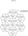
- FIG. 11 shows a drawing for explaining the interference between the cells.
- the base station and the terminal set the cyclic-shift hopping pattern based on the cell to which the user belongs as shown in Equation 8, Table 3, and Table 4.
- H c (n) denotes a cell code value allocated to the cell #c at the transmission time #n
- K denotes the maximum number of the users
- % denotes the modulo operation.
- Table 3 i 0 ... i N- 1 User #0 [ m 0 (0)+ H 0 (0)] %K ... [ m 0 ( N- 1)+ H 0 ( N- 1)] %K
- User #1 [ m 1 (0)+ H 0 (0)] %K ... [ m 1 ( N- 1)+ H 0 ( N- 1)] %K ... ... ... ...
- User #(K-1) [ m K -1 (0)+ H 0 (0)] %K + H 0 (0)] %K ...
- the two users use different cyclic-shift values since the cell #0 and the cell #1 have different cells codes. Accordingly, since the users that belong to the different cells use the different CDM sequences at the same transmission time, the interference between the cells is prevented.
- the basic sequence is fixed and the cyclic-shift is hopped to hop the CDM sequence.
- the basic sequence may be varied with time while the cyclic-shift is hopped such that the interference between the cells is reduced.
- the cyclic-shift hopping pattern according to the exemplary embodiments of the present invention can be applicable to the case where the users are located at the different cells or sectors like a reference signal of a data channel used for a coherent demodulation of the data channel. This exemplary embodiment will be described with reference to FIG. 12 and FIG. 13 .
- FIG 12 shows an example of a method for arranging the reference signals of the data channels in a cellular environment
- FIG. 13 shows an example of data transmission in two sectors located at the same base station. Seven base stations are shown in FIG. 12 for easy description.
- each base station uses different base sequences, i.e., basic sequence numbers u n .
- Each base station includes three sectors, and the three sectors use sequences which are obtained by cyclic-shifting the same basic sequence by the different values. While it has been shown in FIG. 12 that two different cyclic-shift values are allocated to each sector, one cyclic-shift value can be allocated to each sector.
- a user #1 transmits data in a sector ⁇ , and the user #1 is differentiated form the other users of the sector ⁇ by the frequency.
- the data are transmitted in a subframe unit, and the reference signal which is common to all users of the sector ⁇ is transmitted twice in each subframe.
- a user #2 transmits data in a sector ⁇ , and the data transmission structure of the sector ⁇ is similar to the sector ⁇ .
- the interference between the users within one sector does not exist as shown in FIG. 13 .
- the user #1 of the sector ⁇ and the user #2 of the sector P use the same time/frequency resources, and use sequences, which are obtained by cyclic-shifting the same basic sequence by the different values, as the reference signals, respectively.
- a sixth exemplary embodiment of the present invention randomizes the interference between the users by changing the cyclic-shift value with time. At this time, the basic sequence may be changed with time.
- Table 5 shows an example of a cyclic shift hopping pattern and a basic sequence hopping pattern on the reference signal of the data channel. Referring to Table 5, whenever the reference signal is transmitted, the basic sequence number u n and the cyclic-shift, i.e., the CDM sequence number i n is changed.
Landscapes
- Engineering & Computer Science (AREA)
- Signal Processing (AREA)
- Computer Networks & Wireless Communication (AREA)
- Physics & Mathematics (AREA)
- Spectroscopy & Molecular Physics (AREA)
- Power Engineering (AREA)
- Mobile Radio Communication Systems (AREA)
Applications Claiming Priority (6)
| Application Number | Priority Date | Filing Date | Title |
|---|---|---|---|
| KR20060084087 | 2006-09-01 | ||
| KR20060134424 | 2006-12-27 | ||
| KR20070011368 | 2007-02-05 | ||
| KR20070031357 | 2007-03-30 | ||
| KR1020070052549A KR20080020934A (ko) | 2006-09-01 | 2007-05-30 | 통신 시스템의 상향링크 신호 송신 방법, 송신 장치, 생성방법 및 생성 장치 |
| EP07808017.3A EP2062408B1 (en) | 2006-09-01 | 2007-08-31 | Method and apparatus for transmitting uplink signal, and method and apparatus for generating uplink signal in communication system |
Related Parent Applications (2)
| Application Number | Title | Priority Date | Filing Date |
|---|---|---|---|
| EP07808017.3A Division EP2062408B1 (en) | 2006-09-01 | 2007-08-31 | Method and apparatus for transmitting uplink signal, and method and apparatus for generating uplink signal in communication system |
| EP07808017.3A Division-Into EP2062408B1 (en) | 2006-09-01 | 2007-08-31 | Method and apparatus for transmitting uplink signal, and method and apparatus for generating uplink signal in communication system |
Publications (2)
| Publication Number | Publication Date |
|---|---|
| EP2911358A1 EP2911358A1 (en) | 2015-08-26 |
| EP2911358B1 true EP2911358B1 (en) | 2017-07-12 |
Family
ID=39395678
Family Applications (2)
| Application Number | Title | Priority Date | Filing Date |
|---|---|---|---|
| EP15157722.8A Active EP2911358B1 (en) | 2006-09-01 | 2007-08-31 | Method and apparatus for transmitting uplink signal, and method and apparatus for generating uplink signal in communication system |
| EP07808017.3A Active EP2062408B1 (en) | 2006-09-01 | 2007-08-31 | Method and apparatus for transmitting uplink signal, and method and apparatus for generating uplink signal in communication system |
Family Applications After (1)
| Application Number | Title | Priority Date | Filing Date |
|---|---|---|---|
| EP07808017.3A Active EP2062408B1 (en) | 2006-09-01 | 2007-08-31 | Method and apparatus for transmitting uplink signal, and method and apparatus for generating uplink signal in communication system |
Country Status (6)
Families Citing this family (19)
| Publication number | Priority date | Publication date | Assignee | Title |
|---|---|---|---|---|
| RU2419994C2 (ru) * | 2006-11-01 | 2011-05-27 | Квэлкомм Инкорпорейтед | Способ и устройство в гибридной структуре fdm-cdm для каналов управления с одной несущей |
| US9065714B2 (en) | 2007-01-10 | 2015-06-23 | Qualcomm Incorporated | Transmission of information using cyclically shifted sequences |
| US8750917B2 (en) | 2007-05-18 | 2014-06-10 | Qualcomm Incorporated | Multiplexing and power control of uplink control channels in a wireless communication system |
| US8254429B1 (en) * | 2007-10-02 | 2012-08-28 | Apple Inc. | Communication systems and methods |
| US9425916B2 (en) | 2008-12-10 | 2016-08-23 | Sun Patent Trust | Wireless communication terminal apparatus, wireless communication base station apparatus and signal spreading method |
| KR101641971B1 (ko) * | 2009-05-15 | 2016-07-22 | 엘지전자 주식회사 | 무선 통신 시스템에서 사운딩 참조 신호 송신 방법 및 이를 위한 장치 |
| KR101689039B1 (ko) * | 2010-01-07 | 2017-01-03 | 엘지전자 주식회사 | 무선 통신 시스템에서 참조 신호 시퀀스 생성 방법 및 장치 |
| KR101807875B1 (ko) | 2010-03-05 | 2017-12-12 | 엘지전자 주식회사 | 무선 통신 시스템에서 비주기적 사운딩 참조 신호 전송 방법 및 장치 |
| KR101807874B1 (ko) | 2010-03-05 | 2017-12-12 | 엘지전자 주식회사 | 무선 통신 시스템에서 비주기적 사운딩 참조 신호 전송 방법 및 장치 |
| JP5501067B2 (ja) * | 2010-03-30 | 2014-05-21 | シャープ株式会社 | 無線通信システム及び受信装置 |
| WO2013025140A1 (en) * | 2011-08-12 | 2013-02-21 | Telefonaktiebolaget L M Ericsson (Publ) | Methods and apparatuses for handling reference signals in a cellular network |
| KR102210081B1 (ko) * | 2012-05-11 | 2021-02-01 | 팬텍 주식회사 | 무선통신 시스템에서의 참조신호 송수신 방법 및 장치 |
| US9706481B2 (en) | 2013-03-15 | 2017-07-11 | Futurewei Technologies, Inc. | System and method for time-power frequency hopping for D2D discovery |
| US9356676B2 (en) * | 2014-01-30 | 2016-05-31 | Aruba Networks, Inc. | System and methods for adaptive per-user multipath control for spatial multiplexing gain in MIMO systems |
| KR102467048B1 (ko) | 2015-04-09 | 2022-11-14 | 한국전자통신연구원 | 히든 노드 문제와 사용자 단말들의 채널 점유를 고려한 상향 링크 데이터 전송 방법 |
| EP3119023A1 (en) * | 2015-07-16 | 2017-01-18 | Alcatel Lucent | Methods for multiplexing and assigning upink reference signals in a radio communication system with a first network node and a second network node |
| CN105834135A (zh) * | 2016-05-13 | 2016-08-10 | 宋国强 | 一种杀虫灯电网清理方法及装置 |
| US11005620B2 (en) * | 2017-06-16 | 2021-05-11 | Qualcomm Incorporated | Uplink reference signal sequence design in 5G new radio |
| WO2019095239A1 (zh) | 2017-11-16 | 2019-05-23 | Oppo广东移动通信有限公司 | 用于传输控制信息的方法、网络设备和终端设备 |
Family Cites Families (23)
| Publication number | Priority date | Publication date | Assignee | Title |
|---|---|---|---|---|
| US5550809A (en) * | 1992-04-10 | 1996-08-27 | Ericsson Ge Mobile Communications, Inc. | Multiple access coding using bent sequences for mobile radio communications |
| US5963601A (en) | 1996-05-20 | 1999-10-05 | Trimble Navigation Limited | Variable suppression of multipath signal effects |
| US6160803A (en) * | 1998-01-12 | 2000-12-12 | Golden Bridge Technology, Inc. | High processing gain spread spectrum TDMA system and method |
| KR100326182B1 (ko) * | 1998-03-23 | 2002-07-02 | 윤종용 | 부호분할다중접속통신시스템의의사잡음시퀀스발생방법및장치 |
| US7289494B2 (en) * | 2001-12-06 | 2007-10-30 | Pulse-Link, Inc. | Systems and methods for wireless communication over a wide bandwidth channel using a plurality of sub-channels |
| US8045935B2 (en) * | 2001-12-06 | 2011-10-25 | Pulse-Link, Inc. | High data rate transmitter and receiver |
| US7085328B2 (en) * | 2002-12-24 | 2006-08-01 | Realtek Semiconductor Corp. | QAM receiver having joint gain, carrier recovery and equalization adaptation system |
| US7068703B2 (en) * | 2003-02-18 | 2006-06-27 | Qualcomm, Incorporated | Frequency hop sequences for multi-band communication systems |
| US7376117B2 (en) * | 2003-12-02 | 2008-05-20 | Infineon Technologies Ag | Interleaving circuit for a multiband OFDM transceiver |
| US7444134B2 (en) * | 2004-02-13 | 2008-10-28 | Broadcom Corporation | Device and method for transmitting long training sequence for wireless communications |
| US7724777B2 (en) | 2004-06-18 | 2010-05-25 | Qualcomm Incorporated | Quasi-orthogonal multiplexing for a multi-carrier communication system |
| US8385296B2 (en) * | 2004-07-22 | 2013-02-26 | Industry Academic Cooperation Foundation Of Kyunghee University | Multi-carrier CDMA transmitting device and method using block-based multi-carrier spreading |
| US7773535B2 (en) * | 2004-08-12 | 2010-08-10 | Motorola, Inc. | Method and apparatus for closed loop transmission |
| US7664090B2 (en) * | 2004-08-13 | 2010-02-16 | Ipwireless, Inc. | Intra-frame code diversity |
| US7894548B2 (en) * | 2004-09-03 | 2011-02-22 | Qualcomm Incorporated | Spatial spreading with space-time and space-frequency transmit diversity schemes for a wireless communication system |
| SE0402210D0 (sv) * | 2004-09-13 | 2004-09-13 | Ericsson Telefon Ab L M | a telecommunication system |
| US20060104379A1 (en) * | 2004-11-15 | 2006-05-18 | Qinghua Li | Technique to increase a code rate in a MIMO system using virtual channels |
| CN100512053C (zh) * | 2005-05-24 | 2009-07-08 | 上海原动力通信科技有限公司 | 一种确定时分同步码分多址系统用户信道冲激响应的方法 |
| US20070183386A1 (en) * | 2005-08-03 | 2007-08-09 | Texas Instruments Incorporated | Reference Signal Sequences and Multi-User Reference Signal Sequence Allocation |
| US8885628B2 (en) * | 2005-08-08 | 2014-11-11 | Qualcomm Incorporated | Code division multiplexing in a single-carrier frequency division multiple access system |
| US8068464B2 (en) * | 2005-10-27 | 2011-11-29 | Qualcomm Incorporated | Varying scrambling/OVSF codes within a TD-CDMA slot to overcome jamming effect by a dominant interferer |
| US7848438B2 (en) * | 2006-02-14 | 2010-12-07 | Motorola Mobility, Inc. | Method and apparatus for pilot signal transmission |
| JP5044165B2 (ja) * | 2006-08-14 | 2012-10-10 | 株式会社東芝 | マルチアンテナ無線通信システムにおける送信機、受信機及び方法 |
-
2007
- 2007-05-30 KR KR1020070052549A patent/KR20080020934A/ko active Pending
- 2007-08-31 EP EP15157722.8A patent/EP2911358B1/en active Active
- 2007-08-31 CN CN201110127165.1A patent/CN102325112B/zh active Active
- 2007-08-31 EP EP07808017.3A patent/EP2062408B1/en active Active
- 2007-08-31 US US12/439,223 patent/US8391250B2/en active Active
- 2007-08-31 WO PCT/KR2007/004211 patent/WO2008026898A1/en active Application Filing
- 2007-08-31 JP JP2009526543A patent/JP5211057B2/ja active Active
- 2007-08-31 KR KR1020070088097A patent/KR101048498B1/ko active Active
-
2011
- 2011-06-10 KR KR1020110056390A patent/KR101472573B1/ko active Active
-
2013
- 2013-01-28 US US13/751,633 patent/US8902859B2/en not_active Ceased
-
2016
- 2016-12-02 US US15/367,206 patent/USRE49539E1/en active Active
Non-Patent Citations (1)
| Title |
|---|
| None * |
Also Published As
| Publication number | Publication date |
|---|---|
| KR101048498B1 (ko) | 2011-07-11 |
| KR20110084858A (ko) | 2011-07-26 |
| EP2062408B1 (en) | 2015-04-29 |
| USRE49539E1 (en) | 2023-05-30 |
| CN102325112A (zh) | 2012-01-18 |
| US8902859B2 (en) | 2014-12-02 |
| KR101472573B1 (ko) | 2014-12-17 |
| EP2911358A1 (en) | 2015-08-26 |
| CN102325112B (zh) | 2015-02-04 |
| JP2010503260A (ja) | 2010-01-28 |
| US8391250B2 (en) | 2013-03-05 |
| KR20080020959A (ko) | 2008-03-06 |
| US20100067613A1 (en) | 2010-03-18 |
| EP2062408A1 (en) | 2009-05-27 |
| WO2008026898A1 (en) | 2008-03-06 |
| KR20080020934A (ko) | 2008-03-06 |
| US20130148635A1 (en) | 2013-06-13 |
| EP2062408A4 (en) | 2011-12-14 |
| JP5211057B2 (ja) | 2013-06-12 |
Similar Documents
| Publication | Publication Date | Title |
|---|---|---|
| EP2911358B1 (en) | Method and apparatus for transmitting uplink signal, and method and apparatus for generating uplink signal in communication system | |
| EP2158688B1 (en) | Device for designing a sequence for code modulation of data and channel estimation | |
| EP1982490B1 (en) | Method for transmitting pilot for multiple carrier system | |
| US7848438B2 (en) | Method and apparatus for pilot signal transmission | |
| US8068785B2 (en) | Method for resource partition, assignment, transmission and reception for inter-cell interference migration in downlink of OFDM cellular systems | |
| US8184609B2 (en) | System and method for random access in a wireless communication system | |
| EP2195940B1 (en) | Frequency hopping pattern and method for transmitting uplink signals using the same | |
| US7701919B2 (en) | Method of assigning uplink reference signals, and transmitter and receiver thereof | |
| US20090168730A1 (en) | Pilot Signal Allocation Method and Apparatus | |
| US8130711B2 (en) | Method for allocating pilots | |
| EP2183895B1 (en) | Transmission of data using repetition coding with PAPR reduction | |
| US9136992B2 (en) | Method for transmitting and receiving uplink signal in wireless communication system | |
| JP4490831B2 (ja) | 無線通信システム、無線通信装置及び無線通信方法 | |
| JP4255820B2 (ja) | マルチキャリアcdmaシステムおよびそのシステム用送信局と受信局 | |
| EP2122879B1 (en) | Systems and methods for generating sequences that are nearest to a set of sequences with minimum average cross-correlation | |
| JP2007049617A (ja) | 通信装置 | |
| KR20070090617A (ko) | 다수의 부 반송파를 이용하여 데이터를 송수신하는 방법 |
Legal Events
| Date | Code | Title | Description |
|---|---|---|---|
| PUAI | Public reference made under article 153(3) epc to a published international application that has entered the european phase |
Free format text: ORIGINAL CODE: 0009012 |
|
| AC | Divisional application: reference to earlier application |
Ref document number: 2062408 Country of ref document: EP Kind code of ref document: P |
|
| AK | Designated contracting states |
Kind code of ref document: A1 Designated state(s): AT BE BG CH CY CZ DE DK EE ES FI FR GB GR HU IE IS IT LI LT LU LV MC MT NL PL PT RO SE SI SK TR |
|
| 17P | Request for examination filed |
Effective date: 20160226 |
|
| RBV | Designated contracting states (corrected) |
Designated state(s): AT BE BG CH CY CZ DE DK EE ES FI FR GB GR HU IE IS IT LI LT LU LV MC MT NL PL PT RO SE SI SK TR |
|
| GRAP | Despatch of communication of intention to grant a patent |
Free format text: ORIGINAL CODE: EPIDOSNIGR1 |
|
| INTG | Intention to grant announced |
Effective date: 20160916 |
|
| RIN1 | Information on inventor provided before grant (corrected) |
Inventor name: BANG, SEUNG-CHAN Inventor name: PARK, HYEONG-GEUN Inventor name: YI, HYO-SEOK Inventor name: KIM, YOUNG-HOON Inventor name: KO, YOUNG-JO Inventor name: CHANG, KAP-SEOK Inventor name: KIM, IL-GYU |
|
| GRAJ | Information related to disapproval of communication of intention to grant by the applicant or resumption of examination proceedings by the epo deleted |
Free format text: ORIGINAL CODE: EPIDOSDIGR1 |
|
| GRAP | Despatch of communication of intention to grant a patent |
Free format text: ORIGINAL CODE: EPIDOSNIGR1 |
|
| INTC | Intention to grant announced (deleted) | ||
| INTG | Intention to grant announced |
Effective date: 20170202 |
|
| GRAS | Grant fee paid |
Free format text: ORIGINAL CODE: EPIDOSNIGR3 |
|
| GRAA | (expected) grant |
Free format text: ORIGINAL CODE: 0009210 |
|
| AC | Divisional application: reference to earlier application |
Ref document number: 2062408 Country of ref document: EP Kind code of ref document: P |
|
| AK | Designated contracting states |
Kind code of ref document: B1 Designated state(s): AT BE BG CH CY CZ DE DK EE ES FI FR GB GR HU IE IS IT LI LT LU LV MC MT NL PL PT RO SE SI SK TR |
|
| REG | Reference to a national code |
Ref country code: GB Ref legal event code: FG4D |
|
| REG | Reference to a national code |
Ref country code: CH Ref legal event code: EP |
|
| REG | Reference to a national code |
Ref country code: AT Ref legal event code: REF Ref document number: 909291 Country of ref document: AT Kind code of ref document: T Effective date: 20170715 |
|
| REG | Reference to a national code |
Ref country code: IE Ref legal event code: FG4D |
|
| REG | Reference to a national code |
Ref country code: DE Ref legal event code: R096 Ref document number: 602007051656 Country of ref document: DE |
|
| REG | Reference to a national code |
Ref country code: NL Ref legal event code: FP |
|
| REG | Reference to a national code |
Ref country code: FR Ref legal event code: PLFP Year of fee payment: 11 |
|
| REG | Reference to a national code |
Ref country code: LT Ref legal event code: MG4D |
|
| REG | Reference to a national code |
Ref country code: AT Ref legal event code: MK05 Ref document number: 909291 Country of ref document: AT Kind code of ref document: T Effective date: 20170712 |
|
| PG25 | Lapsed in a contracting state [announced via postgrant information from national office to epo] |
Ref country code: AT Free format text: LAPSE BECAUSE OF FAILURE TO SUBMIT A TRANSLATION OF THE DESCRIPTION OR TO PAY THE FEE WITHIN THE PRESCRIBED TIME-LIMIT Effective date: 20170712 Ref country code: FI Free format text: LAPSE BECAUSE OF FAILURE TO SUBMIT A TRANSLATION OF THE DESCRIPTION OR TO PAY THE FEE WITHIN THE PRESCRIBED TIME-LIMIT Effective date: 20170712 Ref country code: LT Free format text: LAPSE BECAUSE OF FAILURE TO SUBMIT A TRANSLATION OF THE DESCRIPTION OR TO PAY THE FEE WITHIN THE PRESCRIBED TIME-LIMIT Effective date: 20170712 Ref country code: SE Free format text: LAPSE BECAUSE OF FAILURE TO SUBMIT A TRANSLATION OF THE DESCRIPTION OR TO PAY THE FEE WITHIN THE PRESCRIBED TIME-LIMIT Effective date: 20170712 |
|
| PG25 | Lapsed in a contracting state [announced via postgrant information from national office to epo] |
Ref country code: IS Free format text: LAPSE BECAUSE OF FAILURE TO SUBMIT A TRANSLATION OF THE DESCRIPTION OR TO PAY THE FEE WITHIN THE PRESCRIBED TIME-LIMIT Effective date: 20171112 Ref country code: LV Free format text: LAPSE BECAUSE OF FAILURE TO SUBMIT A TRANSLATION OF THE DESCRIPTION OR TO PAY THE FEE WITHIN THE PRESCRIBED TIME-LIMIT Effective date: 20170712 Ref country code: PL Free format text: LAPSE BECAUSE OF FAILURE TO SUBMIT A TRANSLATION OF THE DESCRIPTION OR TO PAY THE FEE WITHIN THE PRESCRIBED TIME-LIMIT Effective date: 20170712 Ref country code: BG Free format text: LAPSE BECAUSE OF FAILURE TO SUBMIT A TRANSLATION OF THE DESCRIPTION OR TO PAY THE FEE WITHIN THE PRESCRIBED TIME-LIMIT Effective date: 20171012 Ref country code: ES Free format text: LAPSE BECAUSE OF FAILURE TO SUBMIT A TRANSLATION OF THE DESCRIPTION OR TO PAY THE FEE WITHIN THE PRESCRIBED TIME-LIMIT Effective date: 20170712 Ref country code: GR Free format text: LAPSE BECAUSE OF FAILURE TO SUBMIT A TRANSLATION OF THE DESCRIPTION OR TO PAY THE FEE WITHIN THE PRESCRIBED TIME-LIMIT Effective date: 20171013 |
|
| REG | Reference to a national code |
Ref country code: CH Ref legal event code: PL |
|
| REG | Reference to a national code |
Ref country code: DE Ref legal event code: R097 Ref document number: 602007051656 Country of ref document: DE |
|
| PG25 | Lapsed in a contracting state [announced via postgrant information from national office to epo] |
Ref country code: MC Free format text: LAPSE BECAUSE OF FAILURE TO SUBMIT A TRANSLATION OF THE DESCRIPTION OR TO PAY THE FEE WITHIN THE PRESCRIBED TIME-LIMIT Effective date: 20170712 Ref country code: CH Free format text: LAPSE BECAUSE OF NON-PAYMENT OF DUE FEES Effective date: 20170831 Ref country code: LI Free format text: LAPSE BECAUSE OF NON-PAYMENT OF DUE FEES Effective date: 20170831 Ref country code: RO Free format text: LAPSE BECAUSE OF FAILURE TO SUBMIT A TRANSLATION OF THE DESCRIPTION OR TO PAY THE FEE WITHIN THE PRESCRIBED TIME-LIMIT Effective date: 20170712 Ref country code: DK Free format text: LAPSE BECAUSE OF FAILURE TO SUBMIT A TRANSLATION OF THE DESCRIPTION OR TO PAY THE FEE WITHIN THE PRESCRIBED TIME-LIMIT Effective date: 20170712 Ref country code: CZ Free format text: LAPSE BECAUSE OF FAILURE TO SUBMIT A TRANSLATION OF THE DESCRIPTION OR TO PAY THE FEE WITHIN THE PRESCRIBED TIME-LIMIT Effective date: 20170712 |
|
| PLBE | No opposition filed within time limit |
Free format text: ORIGINAL CODE: 0009261 |
|
| STAA | Information on the status of an ep patent application or granted ep patent |
Free format text: STATUS: NO OPPOSITION FILED WITHIN TIME LIMIT |
|
| REG | Reference to a national code |
Ref country code: IE Ref legal event code: MM4A |
|
| PG25 | Lapsed in a contracting state [announced via postgrant information from national office to epo] |
Ref country code: SK Free format text: LAPSE BECAUSE OF FAILURE TO SUBMIT A TRANSLATION OF THE DESCRIPTION OR TO PAY THE FEE WITHIN THE PRESCRIBED TIME-LIMIT Effective date: 20170712 Ref country code: EE Free format text: LAPSE BECAUSE OF FAILURE TO SUBMIT A TRANSLATION OF THE DESCRIPTION OR TO PAY THE FEE WITHIN THE PRESCRIBED TIME-LIMIT Effective date: 20170712 |
|
| REG | Reference to a national code |
Ref country code: BE Ref legal event code: MM Effective date: 20170831 |
|
| 26N | No opposition filed |
Effective date: 20180413 |
|
| PG25 | Lapsed in a contracting state [announced via postgrant information from national office to epo] |
Ref country code: LU Free format text: LAPSE BECAUSE OF NON-PAYMENT OF DUE FEES Effective date: 20170831 |
|
| REG | Reference to a national code |
Ref country code: FR Ref legal event code: PLFP Year of fee payment: 12 |
|
| PG25 | Lapsed in a contracting state [announced via postgrant information from national office to epo] |
Ref country code: IE Free format text: LAPSE BECAUSE OF NON-PAYMENT OF DUE FEES Effective date: 20170831 |
|
| PG25 | Lapsed in a contracting state [announced via postgrant information from national office to epo] |
Ref country code: SI Free format text: LAPSE BECAUSE OF FAILURE TO SUBMIT A TRANSLATION OF THE DESCRIPTION OR TO PAY THE FEE WITHIN THE PRESCRIBED TIME-LIMIT Effective date: 20170712 Ref country code: BE Free format text: LAPSE BECAUSE OF NON-PAYMENT OF DUE FEES Effective date: 20170831 |
|
| PG25 | Lapsed in a contracting state [announced via postgrant information from national office to epo] |
Ref country code: MT Free format text: LAPSE BECAUSE OF NON-PAYMENT OF DUE FEES Effective date: 20170831 |
|
| PG25 | Lapsed in a contracting state [announced via postgrant information from national office to epo] |
Ref country code: HU Free format text: LAPSE BECAUSE OF FAILURE TO SUBMIT A TRANSLATION OF THE DESCRIPTION OR TO PAY THE FEE WITHIN THE PRESCRIBED TIME-LIMIT; INVALID AB INITIO Effective date: 20070831 |
|
| PG25 | Lapsed in a contracting state [announced via postgrant information from national office to epo] |
Ref country code: CY Free format text: LAPSE BECAUSE OF FAILURE TO SUBMIT A TRANSLATION OF THE DESCRIPTION OR TO PAY THE FEE WITHIN THE PRESCRIBED TIME-LIMIT Effective date: 20170712 |
|
| PG25 | Lapsed in a contracting state [announced via postgrant information from national office to epo] |
Ref country code: TR Free format text: LAPSE BECAUSE OF FAILURE TO SUBMIT A TRANSLATION OF THE DESCRIPTION OR TO PAY THE FEE WITHIN THE PRESCRIBED TIME-LIMIT Effective date: 20170712 |
|
| PG25 | Lapsed in a contracting state [announced via postgrant information from national office to epo] |
Ref country code: PT Free format text: LAPSE BECAUSE OF FAILURE TO SUBMIT A TRANSLATION OF THE DESCRIPTION OR TO PAY THE FEE WITHIN THE PRESCRIBED TIME-LIMIT Effective date: 20170712 |
|
| P01 | Opt-out of the competence of the unified patent court (upc) registered |
Effective date: 20230727 |
|
| PGFP | Annual fee paid to national office [announced via postgrant information from national office to epo] |
Ref country code: DE Payment date: 20240722 Year of fee payment: 18 |
|
| PGFP | Annual fee paid to national office [announced via postgrant information from national office to epo] |
Ref country code: GB Payment date: 20240723 Year of fee payment: 18 |
|
| PGFP | Annual fee paid to national office [announced via postgrant information from national office to epo] |
Ref country code: FR Payment date: 20240723 Year of fee payment: 18 |
|
| PGFP | Annual fee paid to national office [announced via postgrant information from national office to epo] |
Ref country code: IT Payment date: 20240729 Year of fee payment: 18 |
|
| PGFP | Annual fee paid to national office [announced via postgrant information from national office to epo] |
Ref country code: NL Payment date: 20250722 Year of fee payment: 19 |