EP2911220A1 - Cap assembly and secondary battery including the same - Google Patents
Cap assembly and secondary battery including the same Download PDFInfo
- Publication number
- EP2911220A1 EP2911220A1 EP15151989.9A EP15151989A EP2911220A1 EP 2911220 A1 EP2911220 A1 EP 2911220A1 EP 15151989 A EP15151989 A EP 15151989A EP 2911220 A1 EP2911220 A1 EP 2911220A1
- Authority
- EP
- European Patent Office
- Prior art keywords
- cap
- dislocation
- portions
- cap assembly
- assembly
- Prior art date
- Legal status (The legal status is an assumption and is not a legal conclusion. Google has not performed a legal analysis and makes no representation as to the accuracy of the status listed.)
- Granted
Links
Images




Classifications
-
- H—ELECTRICITY
- H01—ELECTRIC ELEMENTS
- H01M—PROCESSES OR MEANS, e.g. BATTERIES, FOR THE DIRECT CONVERSION OF CHEMICAL ENERGY INTO ELECTRICAL ENERGY
- H01M50/00—Constructional details or processes of manufacture of the non-active parts of electrochemical cells other than fuel cells, e.g. hybrid cells
- H01M50/50—Current conducting connections for cells or batteries
- H01M50/572—Means for preventing undesired use or discharge
- H01M50/574—Devices or arrangements for the interruption of current
- H01M50/578—Devices or arrangements for the interruption of current in response to pressure
-
- H—ELECTRICITY
- H01—ELECTRIC ELEMENTS
- H01M—PROCESSES OR MEANS, e.g. BATTERIES, FOR THE DIRECT CONVERSION OF CHEMICAL ENERGY INTO ELECTRICAL ENERGY
- H01M50/00—Constructional details or processes of manufacture of the non-active parts of electrochemical cells other than fuel cells, e.g. hybrid cells
- H01M50/10—Primary casings; Jackets or wrappings
- H01M50/147—Lids or covers
- H01M50/148—Lids or covers characterised by their shape
- H01M50/152—Lids or covers characterised by their shape for cells having curved cross-section, e.g. round or elliptic
-
- H—ELECTRICITY
- H01—ELECTRIC ELEMENTS
- H01M—PROCESSES OR MEANS, e.g. BATTERIES, FOR THE DIRECT CONVERSION OF CHEMICAL ENERGY INTO ELECTRICAL ENERGY
- H01M10/00—Secondary cells; Manufacture thereof
- H01M10/04—Construction or manufacture in general
- H01M10/0422—Cells or battery with cylindrical casing
-
- H—ELECTRICITY
- H01—ELECTRIC ELEMENTS
- H01M—PROCESSES OR MEANS, e.g. BATTERIES, FOR THE DIRECT CONVERSION OF CHEMICAL ENERGY INTO ELECTRICAL ENERGY
- H01M50/00—Constructional details or processes of manufacture of the non-active parts of electrochemical cells other than fuel cells, e.g. hybrid cells
- H01M50/10—Primary casings; Jackets or wrappings
- H01M50/147—Lids or covers
-
- H—ELECTRICITY
- H01—ELECTRIC ELEMENTS
- H01M—PROCESSES OR MEANS, e.g. BATTERIES, FOR THE DIRECT CONVERSION OF CHEMICAL ENERGY INTO ELECTRICAL ENERGY
- H01M50/00—Constructional details or processes of manufacture of the non-active parts of electrochemical cells other than fuel cells, e.g. hybrid cells
- H01M50/30—Arrangements for facilitating escape of gases
-
- H—ELECTRICITY
- H01—ELECTRIC ELEMENTS
- H01M—PROCESSES OR MEANS, e.g. BATTERIES, FOR THE DIRECT CONVERSION OF CHEMICAL ENERGY INTO ELECTRICAL ENERGY
- H01M50/00—Constructional details or processes of manufacture of the non-active parts of electrochemical cells other than fuel cells, e.g. hybrid cells
- H01M50/30—Arrangements for facilitating escape of gases
- H01M50/308—Detachable arrangements, e.g. detachable vent plugs or plug systems
-
- H—ELECTRICITY
- H01—ELECTRIC ELEMENTS
- H01M—PROCESSES OR MEANS, e.g. BATTERIES, FOR THE DIRECT CONVERSION OF CHEMICAL ENERGY INTO ELECTRICAL ENERGY
- H01M50/00—Constructional details or processes of manufacture of the non-active parts of electrochemical cells other than fuel cells, e.g. hybrid cells
- H01M50/30—Arrangements for facilitating escape of gases
- H01M50/317—Re-sealable arrangements
- H01M50/325—Re-sealable arrangements comprising deformable valve members, e.g. elastic or flexible valve members
-
- H—ELECTRICITY
- H01—ELECTRIC ELEMENTS
- H01M—PROCESSES OR MEANS, e.g. BATTERIES, FOR THE DIRECT CONVERSION OF CHEMICAL ENERGY INTO ELECTRICAL ENERGY
- H01M50/00—Constructional details or processes of manufacture of the non-active parts of electrochemical cells other than fuel cells, e.g. hybrid cells
- H01M50/30—Arrangements for facilitating escape of gases
- H01M50/342—Non-re-sealable arrangements
- H01M50/3425—Non-re-sealable arrangements in the form of rupturable membranes or weakened parts, e.g. pierced with the aid of a sharp member
-
- H—ELECTRICITY
- H01—ELECTRIC ELEMENTS
- H01M—PROCESSES OR MEANS, e.g. BATTERIES, FOR THE DIRECT CONVERSION OF CHEMICAL ENERGY INTO ELECTRICAL ENERGY
- H01M50/00—Constructional details or processes of manufacture of the non-active parts of electrochemical cells other than fuel cells, e.g. hybrid cells
- H01M50/30—Arrangements for facilitating escape of gases
- H01M50/375—Vent means sensitive to or responsive to temperature
-
- H—ELECTRICITY
- H01—ELECTRIC ELEMENTS
- H01M—PROCESSES OR MEANS, e.g. BATTERIES, FOR THE DIRECT CONVERSION OF CHEMICAL ENERGY INTO ELECTRICAL ENERGY
- H01M2200/00—Safety devices for primary or secondary batteries
- H01M2200/20—Pressure-sensitive devices
-
- Y—GENERAL TAGGING OF NEW TECHNOLOGICAL DEVELOPMENTS; GENERAL TAGGING OF CROSS-SECTIONAL TECHNOLOGIES SPANNING OVER SEVERAL SECTIONS OF THE IPC; TECHNICAL SUBJECTS COVERED BY FORMER USPC CROSS-REFERENCE ART COLLECTIONS [XRACs] AND DIGESTS
- Y02—TECHNOLOGIES OR APPLICATIONS FOR MITIGATION OR ADAPTATION AGAINST CLIMATE CHANGE
- Y02E—REDUCTION OF GREENHOUSE GAS [GHG] EMISSIONS, RELATED TO ENERGY GENERATION, TRANSMISSION OR DISTRIBUTION
- Y02E60/00—Enabling technologies; Technologies with a potential or indirect contribution to GHG emissions mitigation
- Y02E60/10—Energy storage using batteries
-
- Y—GENERAL TAGGING OF NEW TECHNOLOGICAL DEVELOPMENTS; GENERAL TAGGING OF CROSS-SECTIONAL TECHNOLOGIES SPANNING OVER SEVERAL SECTIONS OF THE IPC; TECHNICAL SUBJECTS COVERED BY FORMER USPC CROSS-REFERENCE ART COLLECTIONS [XRACs] AND DIGESTS
- Y02—TECHNOLOGIES OR APPLICATIONS FOR MITIGATION OR ADAPTATION AGAINST CLIMATE CHANGE
- Y02P—CLIMATE CHANGE MITIGATION TECHNOLOGIES IN THE PRODUCTION OR PROCESSING OF GOODS
- Y02P70/00—Climate change mitigation technologies in the production process for final industrial or consumer products
- Y02P70/50—Manufacturing or production processes characterised by the final manufactured product
Definitions
- the present invention relates to a cap assembly and a secondary battery including the same.
- secondary batteries are made up of an electrode assembly having a cylindrical shape, a can having a cylindrical shape and to which the electrode assembly is combined, an electrolyte that is injected into the can and enables movement of lithium (Li) ions, and a cap assembly combined to a side of the can and preventing leakage of the electrolyte and a separation of the electrode assembly.
- Such secondary batteries generally have capacities of about 2000 to about 4000 mAH, and thus, are mainly mounted in a note PC, a digital camera, a camcorder, and an electric vehicle that require large power capacity.
- the secondary batteries are used in a shape in which a plurality of secondary batteries are connected by as many as needed in series or parallel to be assembled into a hard pack of a predetermined shape by including a protection circuit and to be combined to electronic devices for power supply.
- Methods of manufacturing the secondary batteries include forming an electrode assembly by stacking altogether a negative electrode plate coated with a negative electrode active material, a separator, and a positive electrode plate coated with a positive electrode active material, and winding the negative electrode plate, the separator, and the positive electrode plate in an approximately cylindrical shape.
- the electrode assembly is inserted into a can having a cylindrical shape. Then, an electrolyte is injected to the cylindrical can, and a cap assembly is combined to an upper portion of the cylindrical can, and thus, a Lithium-ion battery having a cylindrical shape is manufactured.
- these secondary batteries have a structure in which a safety vent changes its shape when internal pressure increases due to over-charging and a current is broken by the change of shape of the safety vent portion.
- the current breaking structure including the safety vent, is referred to as a current interrupt device (CID), and it is a component of the cap assembly.
- One or more embodiments of the present invention include a cap assembly and a secondary battery including the same.
- a cap assembly includes a cap-down formed such that at least a portion thereof is opened when external pressure is applied thereon; a vent portion formed such that at least a portion thereof is opened when external pressure is applied thereon; and a cap-up electrically connected with the vent portion.
- the cap-down may include a dislocation portion formed to be open when external pressure is applied thereon, and a second notch portion formed in a boundary region of the dislocation portion to define a region of the dislocation portion and in which a fracture occurs when external pressure is applied thereon.
- the cap-down may further include a support portion formed in the second notch portion and supporting the dislocation portion by connecting the dislocation portion with another region of the cap-down.
- a thickness of the second notch portion may be smaller than a thickness of the dislocation portion.
- the plurality of dislocation portions may form identical angles based on a center of the cap-down.
- the plurality of dislocation portions may be formed by the same radius based on a center of the cap-down.
- the dislocation portion and the second notch portion may be formed in circles.
- the cap-down may include a dislocation portion formed in at least a portion of the cap-down and opened by being fractured when internal pressure of a can increases.
- a thickness of the dislocation portion may be smaller than a thickness of the rest of the cap-down, in which the dislocation portion is not formed.
- the plurality of dislocation portions may form identical angles based on a center of the cap-down.
- the plurality of dislocation portions may be formed by the same radius based on a center of the cap-down.
- the dislocation portion may be formed in a circle.
- An edge of the vent portion may extend toward the outside and be bent to cover an edge of an upper portion of the cap-up.
- An opening may be formed in a center of the cap-down, and the cap assembly may further include a sub-disk covering the opening of the cap-down.
- the cap assembly may further include a sub-disk integrally formed with the cap-down.
- the cap assembly may further include an insulator formed between the vent portion and the cap-down to support the vent portion.
- the insulator may cover an outside edge of at least one of the cap-down, the vent portion, and the cap-up.
- the cap assembly may further include a cover plate formed to cover the insulator and including a fluid hole through which gas flows in a direction toward the cap-up.
- An area of the fluid hole may be 10 mm2 or less.
- the cap-down may include a second lower plate that is molded; a second upper plate that is molded and disposed to be spaced apart from the second lower plate; and a plurality of second bridge portions connecting the second upper plate and the second lower plate, and spaces between adjacent second bridge portions may be sealed by the insulator.
- a secondary battery includes: an electrode assembly; a can including an opening at one end thereof and containing the electrode assembly through the opening; and a cap assembly combined with the opening, wherein the cap assembly includes: a cap-down formed such that at least a portion thereof is opened when internal pressure of the can rises; a vent portion formed such that at least a portion thereof is opened when internal pressure of the can rises; and a cap-up electrically connected with the vent portion.
- the cap-down may include a dislocation portion formed to be opened when internal pressure rises; and a second notch portion formed in a boundary region of the dislocation portion to define a region of the dislocation portion and in which a fracture occurs when internal pressure rises.
- the cap-down may further include a support portion formed in the second notch portion and supporting the dislocation portion by connecting the dislocation portion with another region of the cap-down.
- a thickness of the second notch portion may be smaller than a thickness of the dislocation portion.
- the plurality of dislocation portions may form identical angles based on a center of the cap-down.
- the plurality of dislocation portions may be formed by the same radius based on a center of the cap-down.
- the dislocation portion and the second notch portion may be formed in circles.
- the cap-down may include a dislocation portion formed in at least a portion of the cap-down and opened by being fractured when internal pressure increases.
- a thickness of the dislocation portion may be smaller than a thickness of the rest of the cap-down, in which the dislocation portion is not formed.
- the plurality of dislocation portions may form identical angles based on a center of the cap-down.
- the plurality of dislocation portions may be formed by the same radius based on a center of the cap-down.
- the dislocation portion may be formed in a circle.
- An edge of the vent portion may extend toward the outside and be bent to cover an edge of an upper portion of the cap-up.
- An opening may be formed in a center of the cap-down, and the secondary battery may further include a sub-disk covering the opening of the cap-down.
- the secondary battery may further include a sub-disk integrally formed with the cap-down.
- the secondary battery may further include an insulator formed between the vent portion and the cap-down to support the vent portion.
- the insulator may cover an outside edge of at least one of the cap-down, the vent portion, and the cap-up.
- the secondary battery may further include a cover plate formed to cover the insulator and including a fluid hole through which gas flows in a direction toward the cap-up.
- An area of the fluid hole may be 10 mm2 or less.
- the cap-down may include a second lower plate that is molded, a second upper plate that is molded and disposed to be spaced apart from the second lower plate, and a plurality of second bridge portions connecting the second upper plate and the second lower plate, and spaces between adjacent second bridge portions may be sealed by the insulator.
- the secondary battery 100 includes an electrode assembly 110, a can 140 containing the electrode assembly 110, and a cap assembly 170 mounted to the can 140.
- the electrode assembly 110 may include a first electrode plate 111, a second electrode plate 112, and a separator 113 between the first electrode plate 111 and the second electrode plate 112.
- the electrode assembly 110 may be manufactured by sequentially stacking the first electrode plate 111, the separator 113, and the second electrode plate 112 and winding the first electrode plate 111, the separator 113, and the second electrode plate 112 in a jelly-roll shape.
- the electrode assembly 110 may be formed to correspond to a shape of the can 140.
- the electrode assembly 110 may have an oval jelly-roll shape.
- the can 140 and the electrode assembly 110 are both circular will be described for convenience of explanation.
- the first electrode plate 111 may be a positive electrode film or a negative electrode film.
- the second electrode plate 112 may be a negative electrode film.
- the second electrode plate 112 may be a positive electrode film. That is, the first electrode plate 111 and the second electrode plate 112 are formed to have different electrical polarities, and are not limited to specific electrical polarities. However, hereinafter, for convenience of explanation, a description will be provided of a case in which the first electrode plate 111 is a positive electrode film, and the second electrode plate 112 is a negative electrode film.
- the first electrode plate 111 may include a first active material portion coated with a first active material and a first non-coated portion that is not coated with the first active material.
- the first active material portion may be formed, for example, by coating a portion of at least one surface of an aluminum (Al) plate with the first active material, and, the rest of the Al plate, which is not coated with the first active material, may be the first non-coated portion.
- the first active material may be a positive electrode active material, such as lithium (Li)-containing transition metal oxide, such as LiCoO2, LiNiO2, LiMnO2, and LiMnO4, or a Li chalcogenide compound.
- the second electrode plate 112 may include a second active material portion coated with a second active material and a second non-coated portion that is not coated with the second active material.
- the second active material portion may be formed, for example, by coating a portion of at least one surface of a copper (Cu) plate with the second active material, and, the rest of the Cu plate, which is not coated with the second active material, may be the second non-coated portion.
- the second active material may be for example a negative electrode active material.
- the second active material may be a carbon material, such as crystalline carbon, amorphous carbon, a carbon compound, and a carbon fiber, a Li metal, or a Li alloy.
- the separator 113 may be a porous polymer film, such as a polyethylene (PE) film and a polypropylene (PP) film.
- the separator 113 may further include ceramic particles and may be formed of a solid polyelectrolyte.
- the separator 113 may be formed as an independent film, or may be formed as a nonconductive porous layer on the first electrode plate 111 or the second electrode plate 112.
- a first electrode tab 114 is electrically connected with the first electrode plate 111, and a second electrode tab 115 is electrically connected with the second electrode plate 112.
- An end of the first electrode tab 114 may be connected with the first non-coated portion by welding, etc., and the other end of the first electrode tab 114 may be electrically connected with a current breaking portion 150.
- an end of the second electrode tab 115 may be connected with the second non-coated portion by welding, etc., and the other end of the second electrode tab 115 may be welded to a bottom surface of the can 140.
- the can 140 includes an opening at one side thereof, and the electrode assembly 110 may be contained in the can 140 through the opening.
- the can 140 may have for example a cylindrical shape.
- the can 140 may be formed of a conductive material such as Al, and thus, may protect the electrode assembly 110 from external shock and function as a heat-insulating board that releases heat from charge and discharge operations of the electrode assembly 110 to the outside.
- the can 140 since the bottom surface of the can 140 is electrically connected with the second electrode tab 115 by welding, etc., the can 140 may function as a second electrode.
- a third notch portion 146 may be formed in the bottom surface of the can 140. When internal pressure of the can 140 exceeds a predetermined value, the third notch portion 146 may change its shape or may break to emit gas generated inside the can 140 to the outside.
- a first insulating plate 120 and a second insulating plate 130 may be respectively disposed on an end and the other end of the electrode assembly 110, inside the can 140.
- the first insulating plate 120 may be disposed between an upper surface of the electrode assembly 110 and the cap assembly 170, thereby insulating the electrode assembly 110 from the cap assembly 170.
- the second insulating plate 130 may be disposed between the electrode assembly 110 and the bottom surface of the can 140, thereby insulating the electrode assembly 110 from the can 140.
- the cap assembly 170 is combined with the can 140 and seals the opening of the can 140.
- a beading portion 142 dented toward the inside of the can 140 is formed on the can 140.
- the cap assembly 170 is inserted inside the can 140 through the beading portion 142, and a portion of the can 140 is bent toward the inside thereof above the cap assembly 170 to form a crimping portion 144.
- the cap assembly 170 is combined with the can 140.
- the beading portion 142 and the crimping portion 144 solidly fix and support the cap assembly 170 to the can 140, thereby preventing a dislocation of the cap assembly 170 and leakage of an electrolyte to the outside.
- the cap assembly 170 may include a gasket 141, the current breaking portion 150, and a cap-up 160.
- the gasket 141 is disposed at one side of the can 140 in an approximately ring shape.
- the gasket 141 fixes the current breaking portion 150 and the cap-up 160 according to a shape of the crimping portion 144, and insulates the current breaking portion 150 and the cap-up 160 from the can 140. It is illustrated in FIG. 3 that the cap-up 160 is disposed on the current breaking portion 150, and the cap-up 160 and the current breaking portion 150 are fixed by the gasket 141.
- embodiments of the present invention are not limited thereto. That is, an edge of the current breaking portion 150 may extend to the outside and be bent so as to cover an edge of an upper portion of the cap-up 160 so that the current breaking portion 150 and the cap-up 160 may be combined with each other.
- the current breaking portion 150 and the cap-up 160 may be further fixed by the gasket 141.
- an edge of a vent portion 154 which will be described later, may extend to the outside and be bent to cover the edge of the upper portion of the cap-up 160 so that the current breaking portion 150 and the cap-up 160 may be combined to each other.
- the current breaking portion 150 may break a current when pressure inside the can 140 rises and may emit gas to the outside when internal pressure of the can 140 exceeds a predetermined value by including a first notch portion 155.
- the current breaking portion 150, 250 includes a dislocation portion 153a and 253 which is opened or fractured when internal pressure occurs to provide a passage through which gas may flow in a direction toward the cap-up 160.
- the dislocation portion 153a and 253 may enable gas to evenly diffuse in up and down directions inside the can 140 so that the first notch portion 155 and the third notch portion 146 are fractured together.
- the cap-up 160 may function as a first electrode by being connected to the current breaking portion 150 electrically connected to the first electrode tab 114.
- the cap-up 160 includes a plurality of through-holes 164 for ease of gas emission, and first bridge portions 162 may be formed between the plurality of through-holes 164.
- the cap-up 160 may include a first upper plate 161 and a first lower plate 163 connected to the first bridge portion 162.
- the first upper plate 161 and the first lower plate 163 may be disposed to be spaced apart from each other.
- the first upper plate 161 and the first lower plate 163 may be disposed above and below with respect to each other.
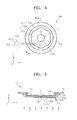
- FIG. 4 is a plan view of an example of the current breaking portion 150 of FIG. 3 .
- FIG. 5 is a cross-sectional view taken along line V-V of FIG. 4 .
- the current breaking portion 150 may, for example, include a cap-down 152, the vent portion 154, an insulator 156, and a sub-disk 158.
- the cap-down 152 includes an opening in the center thereof, and the vent portion 154 is disposed on one surface of the cap-down 152.
- the insulator 156 is disposed in an edge between the cap-down 152 and the vent portion 154, thereby insulating the cap-down 152 from the vent portion 154.
- a gap may be formed between the cap-down 152 and the vent portion 154 by the insulator 156.
- the cap-down 152 may include a second upper plate 152a including an opening in the center thereof, a second lower plate 152b disposed separate from the second upper plate 152a, and a plurality of second bridge portions 152c connecting the second upper plate 152a and the second lower plate 152b.
- the second lower plate 152b and the second upper plate 152a may be formed by molding, and may be disposed on different planes. Also, spaces between adjacent second bridge portions 152c may be sealed by the insulator 156.
- the vent portion 154 may include the first notch portion 155.
- the first notch portion 155 may have a groove shape to be relatively thin, and may change its shape or break to emit gas in a can (not shown) to the outside when internal pressure of the can exceeds a predetermined value.
- the cap-down 152 may include the dislocation portion 153a that is opened when internal pressure of the can rises, and a second notch portion 153b formed at a boundary of the dislocation portion 153a.
- the dislocation portion 153a and the second notch portion 153b may be formed in at least one of two surfaces of the cap-down 152.
- the dislocation portion 153a and the second notch portion 153b may be formed in one surface of the cap-down 152, to which the sub-disk 158 is combined.
- the dislocation portion 153a and the second notch portion 153b may be formed in the other surface of the cap-down 152, which is toward the vent portion 154.
- dislocation portion 153a and the second notch portion 153b may be respectively formed in the surface and the other surface of the cap-down 152.
- descriptions will be provided in detail focusing on the case in which the dislocation portion 153a and the second notch portion 153b are formed in the other surface of the cap-down 152, for convenience of explanation.
- the second notch portion 153b may be formed in the boundary region of the dislocation portion 153a to define a region of the dislocation portion 153a.
- the cap-down 152 may include a support portion 153c formed on the second notch portion 153b and supporting the dislocation portion 153a by connecting the dislocation portion 153a with another region of the cap-down 152.
- the support portion 153c supports the dislocation portion 153a when the second notch portion 153b is fractured, and thus, may prevent the dislocation portion 153a from being broken away to damage or collide with other components.
- the second notch portion 153b is formed to have a different thickness from the dislocation portion 153a.
- the second notch portion 153b may be formed to have a groove shape, etc., to have a relatively smaller thickness than the dislocation portion 153a.
- the second notch portion 153b may fracture when internal pressure of the can exceeds a predetermined value and may separate the dislocation portion 153a from the cap-down 152.
- the second notch portion 153b and the dislocation portion 153a may be formed to have various shapes.
- the dislocation portion 153a and the second notch portion 153b may be formed in a circle, a quadrangle, a triangle, or a polygon.
- the dislocation portion 153a and the second notch portion 153b are formed in circles.
- the dislocation portion 153a is formed in a circle
- the second notch portion 153b is formed as a circle-ring shape, thereby forming the boundary region of the dislocation portion 153a as described above.
- a plurality of dislocation portions 153a and a plurality of second notch portions 153b may be provided.
- the plurality of dislocation portions 153a may be disposed separate from one another.
- each of the plurality of second notch portions 153b may be formed in the boundary region of each of the plurality of dislocation portions 153a to define a region of each of the plurality of dislocation portions 153a.
- Each of the plurality of dislocation portions 153a may form an identical angle based on the center C of the cap-down 152.
- the two dislocation portions 153a may be disposed to face each other with the center C of the cap-down 152 as the center.
- the three dislocation portions 153a may be disposed such that angles between the three adjacent dislocation portions are 120°.
- the number of dislocation portions 153a is not limited thereto. However, hereinafter, a more detailed description will be provided focusing on the case in which the number of dislocation portions 153a is two, for convenience of explanation.
- the plurality of dislocation portions 153a may be disposed at the same radius based on the center C of the cap-down 152.
- the plurality of dislocation portions 153a may be disposed in a radial form based on the center C of the cap-down 152.
- a distance between the center of each of the dislocation portions 153a and the center C of the cap-down 152 may be the same.
- the sub-disk 158 is disposed on the other surface of the cap-down 152 to cover the opening thereof.
- a surface of the sub-disk 158 may be combined to the first electrode tab 114, and the other surface of the sub-disk 158 may be electrically connected to the vent portion 154 by ultrasonic welding, etc., in the opening of the cap-down 152.
- a secondary battery (not shown) may be overheated by external radiant heat, rapid heating, over-charging, etc., and during the heating of the secondary battery, gas may be generated by cyclohexylbenzene (CHB) and biphenyl (BP), which are electrolyte additives. As a result, internal pressure of a can rapidly increases, and the secondary battery may explode.
- CHB cyclohexylbenzene
- BP biphenyl
- a temperature of the gas rises to 600°C or higher, and the insulator 156 between the second bridge portions 152c may be fused by the gas.
- an exposed space is formed between an end of the cap-down 152 and an end of the vent portion 154, and between adjacent second bridge portions 152c and the gas may flow between the cap-down 152 and the vent portion 154 through the space.
- a pressure in a gap between the cap-down 152 and the vent portion 154 increases, and as a result, a shape of the vent portion 154 changes so that a combining portion P1 between the cap-down 152 and the sub-disk 158 is dislocated and a current may be broken.
- the first notch portion 155 is fractured so that the gas inside the can may be released to the outside.
- the dislocation portion 153 may be fractured later than the first notch portion 155. Also, the third notch portion may be fractured together with the dislocation portion 153.
- a side surface of the can may be fractured.
- the side surface of the can when the side surface of the can is fractured, it may transmit heat to neighboring cans or damage external devices so that the stability of the secondary battery may be deteriorated.
- a cap assembly (not shown) and the secondary battery may open the first notch portion 155, the dislocation portion 153a, and the third notch portion to prevent a temperature increase inside the can.
- the cap assembly and the secondary battery may smoothly release combustion gas and materials in the can to the outside during the ignition inside the can so that the stability of the secondary battery may be obtained.
- FIG. 6 is a plan view of another example of the current breaking portion 250 of FIG. 2 .
- FIG. 7 is a cross-sectional view taken along line VII-VII of FIG. 6 .
- a current breaking portion 250 may include a cap-down 252, a vent portion 254, an insulator 256, and a sub-disk 258, according to another embodiment of the present invention.
- the vent portion 254, the insulator 256, and the sub-disk 258 are substantially the same as the vent portion 154, the insulator 156, and the sub-disk 158 described above, respectively.
- the cap-down 252 may include an opening in the center thereof, and a dislocation portion 253 formed around the center thereof.
- the cap-down 252 may include a second upper plate 252a, a second lower plate 252b, and a plurality of second bridge portions 252c, as described above.
- the dislocation portion 253 may be formed in the second lower plate 252b.
- the dislocation portion 253 may be formed in at least one surface of two surfaces of the cap-down 252.
- the dislocation portion 253 may be formed only in a surface of the cap-down 252 to which the sub-disk 258 is attached, or may be formed only in the other surface of the cap-down 252, which faces the vent portion 254.
- the dislocation portion 253 may be formed in the surface and the other surface of the cap-down 252.
- a more detailed description will be provided focusing on the case in which the dislocation portion 253 is formed in the surface of the cap-down 252, for convenience of explanation.
- the dislocation portion 253 may be formed to fracture when a predetermined pressure is applied thereon.
- a thickness of the dislocation portion 253 may be different from a thickness of other portions of the cap-down 252, in which the dislocation portion 253 is not formed.
- the thickness of the dislocation portion 253 may be smaller than the thickness of other portions of the cap-down 252, in which the dislocation portion 253 is not formed.
- the dislocation portion 253 having such a thickness may be fractured and opened when internal pressure of a can (not shown) exceeds a predetermined value.
- the dislocation portion 253 may be formed such that the dislocation portion 253 is opened after the first notch portion 255 is opened.
- the dislocation portion 253 may be formed to have various shapes.
- the dislocation portion 253 may be formed to be circular.
- the dislocation portion 253 may be formed to be quadrangular.
- the shape of the dislocation portion 253 is not limited thereto. However, hereinafter, a more detailed description will be provided focusing on the case in which the shape of the dislocation portion 253 is circular, for convenience of explanation.
- dislocation portions 253 There may be a plurality of dislocation portions 253.
- the plurality of dislocation portions 253 may be disposed to be separate from one another.
- the dislocation portions 253 may be disposed on the same radius and may form identical angles based on the center C of the cap-down 252.
- locations and dispositions of the dislocation portions 253 are substantially the same as the dislocation portions 153a described above, and thus, detailed descriptions thereof will not omitted.
- a more detailed description will be provided focusing on a case in which there are three dislocation portions 253, for convenience of explanation.
- the gas when gas is generated inside the can, the gas may move to an upper and lower portions of the can.
- the gas moving to the upper portion of the can fuses the insulator 256 exposed between the adjacent second bridge portions 252c, and the gas may flow to an exposed space is formed between an end of the cap-down 152 and an end of the vent portion 154, and between adjacent second bridge portions 152c.
- the gas may increase pressure in a gap between the cap-down 252 and the vent portion 254 and may break away the vent portion 254 from the sub-disk 258 by changing a shape of the vent portion 254 so that a current may be broken.
- the gas when the gas is continuously generated, the gas flows between the cap-down 252 and the vent portion 254, thereby increasing the pressure in the gap between the cap-down 252 and the vent portion 254 so that the first notch portion 255 is fractured and the gas inside the can may be released to the outside.
- the dislocation portion 253 and a third notch portion should be fractured together.
- a side surface of the can is fractured as described above and the stability of a secondary battery (not shown) may be deteriorated.
- the dislocation portion 253 may be fractured later than the first notch portion 255. Also, the third notch portion may be fractured together with the dislocation portion 253.
- the dislocation portion 253 When the dislocation portion 253 is formed as described above, the first notch portion 255, the dislocation portion 253, and the third notch portion are fractured so that combustion gas and materials in the can may be smoothly released to the outside.
- a cap assembly (not shown) and the secondary battery may rapidly and smoothly release heat and materials in the can during the ignition in the can, and thus, the stability of the secondary battery may be obtained.
- FIG. 8 is a cross-sectional view of a portion of a secondary battery 300 according to another embodiment of the present invention.
- the secondary battery 300 may include an electrode assembly 310, a can 340 containing the electrode assembly 310, and a cap assembly 370 combined with the can 340. Also, the secondary battery 300 may include a first insulating plate 320 and a second insulating plate 330, inserted in the can 340.
- the first insulating plate 320 and the second insulating plate 330 are substantially the same as the first insulating plate 120 and the second insulating plate 130, respectively.
- the can 340 may include a beading portion 342 and a crimping portion 344.
- the beading portion 342 and the crimping portion 344 are substantially the same as the beading portion 142 and the crimping portion 144 described above, respectively.
- the electrode assembly 310 may include a first electrode plate 311, a second electrode plate 312, and a separator 313.
- the first electrode plate 311, the second electrode plate 312, and the separator 313 are substantially the same as the first electrode plate 111, the second electrode plate 112, and the separator 113 described above, respectively.
- a first electrode tab 314 may be electrically connected with the first electrode plate 311, and a second electrode tab 315 may be electrically connected with the second electrode plate 312.
- the second electrode tab 315 may be attached to a bottom surface of the can 340.
- the cap assembly 370 may include a gasket 341, a current breaking portion 350, and a cap-up 360.
- the gasket 341 and the cap-up 360 are substantially the same as the gasket 141 and the cap-up 160 described above, respectively.
- the current breaking portion 350 may include a vent portion 354 in which a first notch portion 355 is formed, a cap-down 352 in which a dislocation portion 353 is formed, and a sub-disk 358 to which the first electrode tab 314 is attached. Also, the current breaking portion 350 may include an insulator 356 formed to be disposed between the vent portion 354 and the cap-down 352.
- the first notch portion 355, the vent portion 354, the dislocation portion 353, the cap-down 352, and the insulator 356 are substantially the same as the first notch portion 255, the vent portion 254, the dislocation portion 253, the cap-down 252, and the insulator 256 described above, respectively.
- the sub-disk 358 may be formed under the cap-down 352.
- the sub-disk 358 may be integrally formed with the cap-down 352.
- the sub-disk 358 may extend from the cap-down 352 to close a center portion of the cap-down 352 that is open.
- the first electrode tab 314 may be attached and fixed to the sub-disk 358.
- the current breaking portion 350 may operate in substantially the same manner as described above. For example, when the inside of the can 340 is overheated or over-currents are formed in the electrode assembly 310, gas may be generated inside the can 440. Here, the insulator 356 may be fused and removed by a temperature of the gas.
- the gas may move through spaces between adjacent second bridge portions 352c in which the insulator 356 is removed, or may move through a space between an end of a second upper plate 352a and an end of the vent portion 354.
- the gas moving as described above may increase pressure in a gap between the cap-down 352 and the vent portion 354, and may separate the vent portion 354 from the sub-disk 358 of the cap-down 352 to suspend the power supply. Later, if the pressure in the gap between cap-down 352 and the vent portion 354 continues to increase, the gas may fracture the first notch portion 355 of the vent portion 354 to open a portion of the vent portion 354.
- the dislocation portion 353 is fractured to be opened after the first notch portion 355 is fractured so that the gas and heat inside the can 340 may be released to the outside.
- a third notch portion 346 may be fractured together with the dislocation portion 353 to open a lower portion of the can 340.
- the cap assembly 370 and the secondary battery 300 fracture the first notch portion 355, the dislocation portion 353, and the third notch portion 346 to release the gas, heat, and an electrolyte inside the can 340 to the outside, when the internal pressure of the can 340 increases, and thus, the stability of the secondary battery 300 may be obtained.
- FIG. 9 is a cross-sectional view of a portion of a secondary battery 400 according to another embodiment of the present invention.
- the secondary battery 400 may include an electrode assembly 410, a can 440 containing the electrode assembly 410, and a cap assembly 470 combined with the can 440. Also, the secondary battery 400 may include a first insulating plate 420 and a second insulating plate 430 inserted in the can 440.
- the first insulating plate 420 and the second insulating plate 430 are substantially the same as the first insulating plate 120 and the second insulating plate 130 described above, respectively.
- the can 440 may include a beading portion 442 and a crimping portion 444.
- the beading portion 442 and the crimping portion 444 are substantially the same as the beading portion 142 and the crimping portion 144 described above, respectively.
- the electrode assembly 410 may include a first electrode plate 411, a second electrode plate 412, and a separator 413.
- the first electrode plate 411, the second electrode plate 412, and the separator 413 are substantially the same as the first electrode plate 111, the second electrode plate 112, and the separator 113 described above, respectively.
- a first electrode tab 414 may be electrically connected with the first electrode plate 411, and a second electrode tab 415 may be electrically connected with the second electrode plate 412.
- the second electrode tab 415 may be attached to a bottom surface of the can 440.
- the cap assembly 470 may include a gasket 441, a current breaking portion 450, a cap-up 460, and a cover plate 480.
- the gasket 441 and the cap-up 460 are substantially the same as the gasket 141 and the cap-up 160 described above, respectively.
- the current breaking portion 450 may include a vent portion 454 in which a first notch portion 455 is formed. Also, the current breaking portion 450 may include a cap-down 452 in which a second notch portion 453b and a dislocation portion 453a are formed, and an insulator 456 formed between the cap-down 452 and the vent portion 454. The current breaking portion 450 may include a sub-disk 458 connected to the cap-down 452.
- the dislocation portion 453a may be connected to another portion of the cap-down 452 by a support portion (not shown) formed on the second notch portion 453b.
- the sub-disk 458 may be integrally formed with the cap-down 452 or may be separately formed from the cap-down 452 and attached to the cap-down 452.
- the sub-disk 458 is integrally formed with the cap-down 452, for convenience of explanation.
- the first notch portion 455 and the second notch portion 453b may be formed to have a ring-shape.
- a diameter of the first notch portion 455 may be larger than a diameter of the second notch portion 453b.
- the cap-down 452 may include a first upper plate 452a, a first lower plate 452b, and a first bridge portion 452c.
- the first bridge portion 452c may connect the first upper plate 452a and the first lower plate 452b, and spaces may be formed between a plurality of adjacent first bridge portions 452c.
- gas may flow between the adjacent first bridge portions 452c.
- the insulator 456 may be disposed between the vent portion 454 and the cap-down 452 and may separate at least a portion of the cap-down 452 from the vent portion 454.
- the insulator 456 may be formed to cover an outside edge of at least one of the vent portion 454, the cap-down 452, and the cap-up 460.
- the insulator 456 may be formed to completely seal the space between the vent portion 454 and the cap-down 452.
- a detailed description will be provided focusing on the case in which the insulator 456 is formed to cover the outside edge of the vent portion 454, the cap-down 452, and the cap-up 460, for convenience of explanation.
- the cover plate 480 may be formed to cover the insulator 456.
- at least one fluid hole 481 may be formed in the cover plate 480.
- gas generated in the can 440 may flow in a direction toward the cap-up 460 from the inside of the can 440 through the fluid hole 481.
- An area of the fluid hole 481 may be 10 mm2 or less.
- the gas inside the can 440 may move too rapidly, or heat inside the can 440 may be excessively transmitted to the cap assembly 470 so that the cap assembly 470 may be damaged or separated from the can 440.
- gas may be generated inside the can 440 and the gas may pass through the fluid hole 481 and fuse the insulator 456 so that the gas may be injected to a space between the vent portion 454 and the cap-down 452.
- vent portion 454 and at least a portion of the cap-down 452 may maintain a state in which the vent portion 454 and the at least a portion of the cap-down 452 contact each other, and later may be separated from each other.
- the cover plate 480 and the cap-down 452 contact each other, the first electrode tab 414 connected to the cover plate 480 may be short circuited.
- pressure between the vent portion 454 and the cap-down 452 may also increase.
- the pressure between the vent portion 454 and the cap-down 452 reaches pressure by which the first notch portion 455 is fractured, the first notch portion 455 is fractured so that at least a portion of the vent portion 454 may be open.
- the second notch portion 453b is fractured so that the dislocation portion 453a may be open.
- the third notch portion 446 may be also fractured.
- the gas, heat, and an electrolyte of the can 440 may be released in up and down directions of the can 440.
- the cap assembly 470 and the secondary battery 400 may release the gas and heat in up and down directions of the can 440 when the gas and heat are generated due to the heating or explosion inside the can 440. Accordingly, the can 440 may be prevented from having a temperature inside thereof increased and a fractured side surface thereof.
- the cap assembly 470 and the secondary battery 400 smoothly release the gas, heat, and electrolyte inside the can 440 to the outside, and thus, the stability of the secondary battery 400 may be obtained.
Landscapes
- Chemical & Material Sciences (AREA)
- Chemical Kinetics & Catalysis (AREA)
- Electrochemistry (AREA)
- General Chemical & Material Sciences (AREA)
- Engineering & Computer Science (AREA)
- Manufacturing & Machinery (AREA)
- Gas Exhaust Devices For Batteries (AREA)
- Sealing Battery Cases Or Jackets (AREA)
- Connection Of Batteries Or Terminals (AREA)
- Apparatus For Radiation Diagnosis (AREA)
Abstract
Description
- The present invention relates to a cap assembly and a secondary battery including the same.
- In general, secondary batteries are made up of an electrode assembly having a cylindrical shape, a can having a cylindrical shape and to which the electrode assembly is combined, an electrolyte that is injected into the can and enables movement of lithium (Li) ions, and a cap assembly combined to a side of the can and preventing leakage of the electrolyte and a separation of the electrode assembly. Such secondary batteries generally have capacities of about 2000 to about 4000 mAH, and thus, are mainly mounted in a note PC, a digital camera, a camcorder, and an electric vehicle that require large power capacity.
- For example, the secondary batteries are used in a shape in which a plurality of secondary batteries are connected by as many as needed in series or parallel to be assembled into a hard pack of a predetermined shape by including a protection circuit and to be combined to electronic devices for power supply. Methods of manufacturing the secondary batteries include forming an electrode assembly by stacking altogether a negative electrode plate coated with a negative electrode active material, a separator, and a positive electrode plate coated with a positive electrode active material, and winding the negative electrode plate, the separator, and the positive electrode plate in an approximately cylindrical shape.
- Next, the electrode assembly is inserted into a can having a cylindrical shape. Then, an electrolyte is injected to the cylindrical can, and a cap assembly is combined to an upper portion of the cylindrical can, and thus, a Lithium-ion battery having a cylindrical shape is manufactured.
- In order to prevent explosion and ignition in the secondary batteries, these secondary batteries have a structure in which a safety vent changes its shape when internal pressure increases due to over-charging and a current is broken by the change of shape of the safety vent portion. Generally, the current breaking structure, including the safety vent, is referred to as a current interrupt device (CID), and it is a component of the cap assembly.
- One or more embodiments of the present invention include a cap assembly and a secondary battery including the same.
- Additional aspects will be set forth in part in the description which follows and, in part, will be apparent from the description, or may be learned by practice of the presented embodiments.
- According to one or more embodiments of the present invention, a cap assembly includes a cap-down formed such that at least a portion thereof is opened when external pressure is applied thereon; a vent portion formed such that at least a portion thereof is opened when external pressure is applied thereon; and a cap-up electrically connected with the vent portion.
- The cap-down may include a dislocation portion formed to be open when external pressure is applied thereon, and a second notch portion formed in a boundary region of the dislocation portion to define a region of the dislocation portion and in which a fracture occurs when external pressure is applied thereon.
- The cap-down may further include a support portion formed in the second notch portion and supporting the dislocation portion by connecting the dislocation portion with another region of the cap-down.
- A thickness of the second notch portion may be smaller than a thickness of the dislocation portion.
- There may be at least one dislocation portion and at least one second notch portion; and when there are a plurality of dislocation portions and a plurality of second notch portions, the plurality of dislocation portions may be formed separate from one another, and each of the plurality of second notch portions may be formed in a boundary region of each of the plurality of dislocation portions to define a region of each of the plurality of dislocation portions.
- The plurality of dislocation portions may form identical angles based on a center of the cap-down.
- The plurality of dislocation portions may be formed by the same radius based on a center of the cap-down.
- The dislocation portion and the second notch portion may be formed in circles.
- The cap-down may include a dislocation portion formed in at least a portion of the cap-down and opened by being fractured when internal pressure of a can increases.
- A thickness of the dislocation portion may be smaller than a thickness of the rest of the cap-down, in which the dislocation portion is not formed.
- There may be a plurality of dislocation portions and the plurality of dislocation portions may be formed separate from one another.
- The plurality of dislocation portions may form identical angles based on a center of the cap-down.
- The plurality of dislocation portions may be formed by the same radius based on a center of the cap-down.
- The dislocation portion may be formed in a circle.
- An edge of the vent portion may extend toward the outside and be bent to cover an edge of an upper portion of the cap-up.
- An opening may be formed in a center of the cap-down, and the cap assembly may further include a sub-disk covering the opening of the cap-down.
- The cap assembly may further include a sub-disk integrally formed with the cap-down.
- The cap assembly may further include an insulator formed between the vent portion and the cap-down to support the vent portion.
- The insulator may cover an outside edge of at least one of the cap-down, the vent portion, and the cap-up.
- The cap assembly may further include a cover plate formed to cover the insulator and including a fluid hole through which gas flows in a direction toward the cap-up.
- An area of the fluid hole may be 10 mm2 or less.
- The cap-down may include a second lower plate that is molded; a second upper plate that is molded and disposed to be spaced apart from the second lower plate; and a plurality of second bridge portions connecting the second upper plate and the second lower plate, and spaces between adjacent second bridge portions may be sealed by the insulator.
- According to one or more embodiments of the present invention, a secondary battery includes: an electrode assembly; a can including an opening at one end thereof and containing the electrode assembly through the opening; and a cap assembly combined with the opening, wherein the cap assembly includes: a cap-down formed such that at least a portion thereof is opened when internal pressure of the can rises; a vent portion formed such that at least a portion thereof is opened when internal pressure of the can rises; and a cap-up electrically connected with the vent portion.
- The cap-down may include a dislocation portion formed to be opened when internal pressure rises; and a second notch portion formed in a boundary region of the dislocation portion to define a region of the dislocation portion and in which a fracture occurs when internal pressure rises.
- The cap-down may further include a support portion formed in the second notch portion and supporting the dislocation portion by connecting the dislocation portion with another region of the cap-down.
- A thickness of the second notch portion may be smaller than a thickness of the dislocation portion.
- There may be at least one dislocation portion and at least one second notch portion; and when there are a plurality of dislocation portions and a plurality of second notch portions, the plurality of dislocation portions may be formed separate from one another, and each of the plurality of second notch portions may be formed in a boundary region of each of the plurality of dislocation portions to define a region of each of the plurality of dislocation portions.
- The plurality of dislocation portions may form identical angles based on a center of the cap-down.
- The plurality of dislocation portions may be formed by the same radius based on a center of the cap-down.
- The dislocation portion and the second notch portion may be formed in circles.
- The cap-down may include a dislocation portion formed in at least a portion of the cap-down and opened by being fractured when internal pressure increases.
- A thickness of the dislocation portion may be smaller than a thickness of the rest of the cap-down, in which the dislocation portion is not formed.
- There may be a plurality of dislocation portions and the plurality of dislocation portions may be formed separate from one another.
- The plurality of dislocation portions may form identical angles based on a center of the cap-down.
- The plurality of dislocation portions may be formed by the same radius based on a center of the cap-down.
- The dislocation portion may be formed in a circle.
- An edge of the vent portion may extend toward the outside and be bent to cover an edge of an upper portion of the cap-up.
- An opening may be formed in a center of the cap-down, and the secondary battery may further include a sub-disk covering the opening of the cap-down.
- The secondary battery may further include a sub-disk integrally formed with the cap-down.
- The secondary battery may further include an insulator formed between the vent portion and the cap-down to support the vent portion.
- The insulator may cover an outside edge of at least one of the cap-down, the vent portion, and the cap-up.
- The secondary battery may further include a cover plate formed to cover the insulator and including a fluid hole through which gas flows in a direction toward the cap-up.
- An area of the fluid hole may be 10 mm2 or less.
- The cap-down may include a second lower plate that is molded, a second upper plate that is molded and disposed to be spaced apart from the second lower plate, and a plurality of second bridge portions connecting the second upper plate and the second lower plate, and spaces between adjacent second bridge portions may be sealed by the insulator.
- These and/or other aspects will become apparent and more readily appreciated from the following description of the embodiments, taken in conjunction with the accompanying drawings in which:
-
FIG. 1 is a perspective view of a secondary battery according to an embodiment of the present invention; -
FIG. 2 is an exploded perspective view of the secondary battery ofFIG. 1 ; -
FIG. 3 is a cross-sectional view taken along line III-III ofFIG. 1 ; -
FIG. 4 is a plan view of an example of a current breaking portion ofFIG. 3 ; -
FIG. 5 is a cross-sectional view taken along line V-V ofFIG. 4 ; -
FIG. 6 is a plan view of another example of a current breaking portion ofFIG. 3 ; -
FIG. 7 is a cross-sectional view taken along line VII-VII ofFIG. 6 ; -
FIG. 8 is a cross-sectional view of a portion of a secondary battery according to another embodiment of the present invention; and -
FIG. 9 is a cross-sectional view of a portion of a secondary battery according to another embodiment of the present invention. - Referring to
FIGS. 1 to 3 , thesecondary battery 100 includes anelectrode assembly 110, a can 140 containing theelectrode assembly 110, and acap assembly 170 mounted to thecan 140. - The
electrode assembly 110 may include afirst electrode plate 111, asecond electrode plate 112, and aseparator 113 between thefirst electrode plate 111 and thesecond electrode plate 112. For example, theelectrode assembly 110 may be manufactured by sequentially stacking thefirst electrode plate 111, theseparator 113, and thesecond electrode plate 112 and winding thefirst electrode plate 111, theseparator 113, and thesecond electrode plate 112 in a jelly-roll shape. - Here, the
electrode assembly 110 may be formed to correspond to a shape of thecan 140. For example, when thecan 140 has an oval shape, theelectrode assembly 110 may have an oval jelly-roll shape. However, hereinafter, a case in which thecan 140 and theelectrode assembly 110 are both circular will be described for convenience of explanation. - The
first electrode plate 111 may be a positive electrode film or a negative electrode film. When thefirst electrode plate 111 is a positive electrode film, thesecond electrode plate 112 may be a negative electrode film. On the contrary, when thefirst electrode plate 111 is a negative electrode film, thesecond electrode plate 112 may be a positive electrode film. That is, thefirst electrode plate 111 and thesecond electrode plate 112 are formed to have different electrical polarities, and are not limited to specific electrical polarities. However, hereinafter, for convenience of explanation, a description will be provided of a case in which thefirst electrode plate 111 is a positive electrode film, and thesecond electrode plate 112 is a negative electrode film. - The
first electrode plate 111 may include a first active material portion coated with a first active material and a first non-coated portion that is not coated with the first active material. The first active material portion may be formed, for example, by coating a portion of at least one surface of an aluminum (Al) plate with the first active material, and, the rest of the Al plate, which is not coated with the first active material, may be the first non-coated portion. The first active material may be a positive electrode active material, such as lithium (Li)-containing transition metal oxide, such as LiCoO2, LiNiO2, LiMnO2, and LiMnO4, or a Li chalcogenide compound. - The
second electrode plate 112 may include a second active material portion coated with a second active material and a second non-coated portion that is not coated with the second active material. The second active material portion may be formed, for example, by coating a portion of at least one surface of a copper (Cu) plate with the second active material, and, the rest of the Cu plate, which is not coated with the second active material, may be the second non-coated portion. The second active material may be for example a negative electrode active material. In particular, the second active material may be a carbon material, such as crystalline carbon, amorphous carbon, a carbon compound, and a carbon fiber, a Li metal, or a Li alloy. - The
separator 113 may be a porous polymer film, such as a polyethylene (PE) film and a polypropylene (PP) film. Theseparator 113 may further include ceramic particles and may be formed of a solid polyelectrolyte. Theseparator 113 may be formed as an independent film, or may be formed as a nonconductive porous layer on thefirst electrode plate 111 or thesecond electrode plate 112. - A
first electrode tab 114 is electrically connected with thefirst electrode plate 111, and asecond electrode tab 115 is electrically connected with thesecond electrode plate 112. An end of thefirst electrode tab 114 may be connected with the first non-coated portion by welding, etc., and the other end of thefirst electrode tab 114 may be electrically connected with acurrent breaking portion 150. Also, an end of thesecond electrode tab 115 may be connected with the second non-coated portion by welding, etc., and the other end of thesecond electrode tab 115 may be welded to a bottom surface of thecan 140. - The can 140 includes an opening at one side thereof, and the
electrode assembly 110 may be contained in thecan 140 through the opening. The can 140 may have for example a cylindrical shape. The can 140 may be formed of a conductive material such as Al, and thus, may protect theelectrode assembly 110 from external shock and function as a heat-insulating board that releases heat from charge and discharge operations of theelectrode assembly 110 to the outside. In addition, since the bottom surface of thecan 140 is electrically connected with thesecond electrode tab 115 by welding, etc., thecan 140 may function as a second electrode. - A
third notch portion 146 may be formed in the bottom surface of thecan 140. When internal pressure of thecan 140 exceeds a predetermined value, thethird notch portion 146 may change its shape or may break to emit gas generated inside thecan 140 to the outside. - A first insulating
plate 120 and a second insulatingplate 130 may be respectively disposed on an end and the other end of theelectrode assembly 110, inside thecan 140. The first insulatingplate 120 may be disposed between an upper surface of theelectrode assembly 110 and thecap assembly 170, thereby insulating theelectrode assembly 110 from thecap assembly 170. The second insulatingplate 130 may be disposed between theelectrode assembly 110 and the bottom surface of thecan 140, thereby insulating theelectrode assembly 110 from thecan 140. - The
cap assembly 170 is combined with thecan 140 and seals the opening of thecan 140. In detail, abeading portion 142 dented toward the inside of thecan 140 is formed on thecan 140. Thecap assembly 170 is inserted inside thecan 140 through thebeading portion 142, and a portion of thecan 140 is bent toward the inside thereof above thecap assembly 170 to form a crimpingportion 144. Thus, thecap assembly 170 is combined with thecan 140. Thebeading portion 142 and the crimpingportion 144 solidly fix and support thecap assembly 170 to thecan 140, thereby preventing a dislocation of thecap assembly 170 and leakage of an electrolyte to the outside. - The
cap assembly 170 may include agasket 141, thecurrent breaking portion 150, and a cap-up 160. - The
gasket 141 is disposed at one side of thecan 140 in an approximately ring shape. Thegasket 141 fixes thecurrent breaking portion 150 and the cap-up 160 according to a shape of the crimpingportion 144, and insulates thecurrent breaking portion 150 and the cap-up 160 from thecan 140. It is illustrated inFIG. 3 that the cap-up 160 is disposed on thecurrent breaking portion 150, and the cap-up 160 and thecurrent breaking portion 150 are fixed by thegasket 141. However, embodiments of the present invention are not limited thereto. That is, an edge of thecurrent breaking portion 150 may extend to the outside and be bent so as to cover an edge of an upper portion of the cap-up 160 so that thecurrent breaking portion 150 and the cap-up 160 may be combined with each other. In this state, thecurrent breaking portion 150 and the cap-up 160 may be further fixed by thegasket 141. For example, an edge of avent portion 154, which will be described later, may extend to the outside and be bent to cover the edge of the upper portion of the cap-up 160 so that thecurrent breaking portion 150 and the cap-up 160 may be combined to each other. - The
current breaking portion 150 may break a current when pressure inside thecan 140 rises and may emit gas to the outside when internal pressure of thecan 140 exceeds a predetermined value by including afirst notch portion 155. Also, thecurrent breaking portion dislocation portion up 160. Here, thedislocation portion can 140 so that thefirst notch portion 155 and thethird notch portion 146 are fractured together. - The cap-
up 160 may function as a first electrode by being connected to thecurrent breaking portion 150 electrically connected to thefirst electrode tab 114. The cap-up 160 includes a plurality of through-holes 164 for ease of gas emission, andfirst bridge portions 162 may be formed between the plurality of through-holes 164. Here, the cap-up 160 may include a firstupper plate 161 and a firstlower plate 163 connected to thefirst bridge portion 162. In particular, the firstupper plate 161 and the firstlower plate 163 may be disposed to be spaced apart from each other. For example, the firstupper plate 161 and the firstlower plate 163 may be disposed above and below with respect to each other. - Hereinafter, the
current breaking portion 150 will be described in detail. -
FIG. 4 is a plan view of an example of thecurrent breaking portion 150 ofFIG. 3 .FIG. 5 is a cross-sectional view taken along line V-V ofFIG. 4 . - Referring to
FIGS. 4 and 5 , thecurrent breaking portion 150 may, for example, include a cap-down 152, thevent portion 154, aninsulator 156, and a sub-disk 158. - The cap-down 152 includes an opening in the center thereof, and the
vent portion 154 is disposed on one surface of the cap-down 152. Theinsulator 156 is disposed in an edge between the cap-down 152 and thevent portion 154, thereby insulating the cap-down 152 from thevent portion 154. In addition, a gap may be formed between the cap-down 152 and thevent portion 154 by theinsulator 156. - The cap-down 152 may include a second
upper plate 152a including an opening in the center thereof, a secondlower plate 152b disposed separate from the secondupper plate 152a, and a plurality ofsecond bridge portions 152c connecting the secondupper plate 152a and the secondlower plate 152b. Here, the secondlower plate 152b and the secondupper plate 152a may be formed by molding, and may be disposed on different planes. Also, spaces between adjacentsecond bridge portions 152c may be sealed by theinsulator 156. - The
vent portion 154 may include thefirst notch portion 155. Thefirst notch portion 155 may have a groove shape to be relatively thin, and may change its shape or break to emit gas in a can (not shown) to the outside when internal pressure of the can exceeds a predetermined value. - The cap-down 152 may include the
dislocation portion 153a that is opened when internal pressure of the can rises, and asecond notch portion 153b formed at a boundary of thedislocation portion 153a. Here, thedislocation portion 153a and thesecond notch portion 153b may be formed in at least one of two surfaces of the cap-down 152. For example, thedislocation portion 153a and thesecond notch portion 153b may be formed in one surface of the cap-down 152, to which the sub-disk 158 is combined. Also, thedislocation portion 153a and thesecond notch portion 153b may be formed in the other surface of the cap-down 152, which is toward thevent portion 154. In addition, thedislocation portion 153a and thesecond notch portion 153b may be respectively formed in the surface and the other surface of the cap-down 152. However, hereinafter, descriptions will be provided in detail focusing on the case in which thedislocation portion 153a and thesecond notch portion 153b are formed in the other surface of the cap-down 152, for convenience of explanation. - The
second notch portion 153b may be formed in the boundary region of thedislocation portion 153a to define a region of thedislocation portion 153a. - Also, the cap-down 152 may include a
support portion 153c formed on thesecond notch portion 153b and supporting thedislocation portion 153a by connecting thedislocation portion 153a with another region of the cap-down 152. In particular, thesupport portion 153c supports thedislocation portion 153a when thesecond notch portion 153b is fractured, and thus, may prevent thedislocation portion 153a from being broken away to damage or collide with other components. - The
second notch portion 153b is formed to have a different thickness from thedislocation portion 153a. For example, thesecond notch portion 153b may be formed to have a groove shape, etc., to have a relatively smaller thickness than thedislocation portion 153a. In particular, thesecond notch portion 153b may fracture when internal pressure of the can exceeds a predetermined value and may separate thedislocation portion 153a from the cap-down 152. - Also, the
second notch portion 153b and thedislocation portion 153a may be formed to have various shapes. For example, thedislocation portion 153a and thesecond notch portion 153b may be formed in a circle, a quadrangle, a triangle, or a polygon. Hereinafter, descriptions will be provided in detail focusing on the case in which thedislocation portion 153a and thesecond notch portion 153b are formed in circles. Particularly, thedislocation portion 153a is formed in a circle, and thesecond notch portion 153b is formed as a circle-ring shape, thereby forming the boundary region of thedislocation portion 153a as described above. - A plurality of
dislocation portions 153a and a plurality ofsecond notch portions 153b may be provided. For example, the plurality ofdislocation portions 153a may be disposed separate from one another. Here, each of the plurality ofsecond notch portions 153b may be formed in the boundary region of each of the plurality ofdislocation portions 153a to define a region of each of the plurality ofdislocation portions 153a. - Each of the plurality of
dislocation portions 153a may form an identical angle based on the center C of the cap-down 152. For example, when there are twodislocation portions 153a, the twodislocation portions 153a may be disposed to face each other with the center C of the cap-down 152 as the center. Also, when there are threedislocation portions 153a, the threedislocation portions 153a may be disposed such that angles between the three adjacent dislocation portions are 120°. Here, the number ofdislocation portions 153a is not limited thereto. However, hereinafter, a more detailed description will be provided focusing on the case in which the number ofdislocation portions 153a is two, for convenience of explanation. - The plurality of
dislocation portions 153a may be disposed at the same radius based on the center C of the cap-down 152. In particular, the plurality ofdislocation portions 153a may be disposed in a radial form based on the center C of the cap-down 152. In detail, a distance between the center of each of thedislocation portions 153a and the center C of the cap-down 152 may be the same. - The sub-disk 158 is disposed on the other surface of the cap-down 152 to cover the opening thereof. A surface of the sub-disk 158 may be combined to the
first electrode tab 114, and the other surface of the sub-disk 158 may be electrically connected to thevent portion 154 by ultrasonic welding, etc., in the opening of the cap-down 152. - Hereinafter, an operation of the
current breaking portion 150 will be described in detail. - A secondary battery (not shown) may be overheated by external radiant heat, rapid heating, over-charging, etc., and during the heating of the secondary battery, gas may be generated by cyclohexylbenzene (CHB) and biphenyl (BP), which are electrolyte additives. As a result, internal pressure of a can rapidly increases, and the secondary battery may explode.
- As illustrated in
FIG. 5 , when gas is generated inside the can, a temperature of the gas rises to 600°C or higher, and theinsulator 156 between thesecond bridge portions 152c may be fused by the gas. - When the
insulator 156 is fused, an exposed space is formed between an end of the cap-down 152 and an end of thevent portion 154, and between adjacentsecond bridge portions 152c and the gas may flow between the cap-down 152 and thevent portion 154 through the space. Here, a pressure in a gap between the cap-down 152 and thevent portion 154 increases, and as a result, a shape of thevent portion 154 changes so that a combining portion P1 between the cap-down 152 and the sub-disk 158 is dislocated and a current may be broken. - Also, when the gas continuously flows between the cap-down 152 and the
vent portion 154, and the pressure in the gap between the cap-down 152 and thevent portion 154 further increases, thefirst notch portion 155 is fractured so that the gas inside the can may be released to the outside. - As described above, when a predetermined time lapses after the
first notch portion 155 is fractured, an explosion may occur inside the can. Here, the dislocation portion 153 may be fractured later than thefirst notch portion 155. Also, the third notch portion may be fractured together with the dislocation portion 153. - In the case above, when the third notch portion or the
dislocation portion 153a is not fractured, a side surface of the can may be fractured. Here, when the side surface of the can is fractured, it may transmit heat to neighboring cans or damage external devices so that the stability of the secondary battery may be deteriorated. - As shown above, a cap assembly (not shown) and the secondary battery may open the
first notch portion 155, thedislocation portion 153a, and the third notch portion to prevent a temperature increase inside the can. - Thus, the cap assembly and the secondary battery may smoothly release combustion gas and materials in the can to the outside during the ignition inside the can so that the stability of the secondary battery may be obtained.
-
FIG. 6 is a plan view of another example of thecurrent breaking portion 250 ofFIG. 2 .FIG. 7 is a cross-sectional view taken along line VII-VII ofFIG. 6 . - Referring to
FIGS. 6 and 7 , acurrent breaking portion 250 may include a cap-down 252, avent portion 254, aninsulator 256, and a sub-disk 258, according to another embodiment of the present invention. Here, thevent portion 254, theinsulator 256, and the sub-disk 258 are substantially the same as thevent portion 154, theinsulator 156, and the sub-disk 158 described above, respectively. - The cap-down 252 may include an opening in the center thereof, and a
dislocation portion 253 formed around the center thereof. In particular, the cap-down 252 may include a secondupper plate 252a, a secondlower plate 252b, and a plurality ofsecond bridge portions 252c, as described above. Here, thedislocation portion 253 may be formed in the secondlower plate 252b. - The
dislocation portion 253 may be formed in at least one surface of two surfaces of the cap-down 252. For example, thedislocation portion 253 may be formed only in a surface of the cap-down 252 to which the sub-disk 258 is attached, or may be formed only in the other surface of the cap-down 252, which faces thevent portion 254. Also, thedislocation portion 253 may be formed in the surface and the other surface of the cap-down 252. However, a more detailed description will be provided focusing on the case in which thedislocation portion 253 is formed in the surface of the cap-down 252, for convenience of explanation. - The
dislocation portion 253 may be formed to fracture when a predetermined pressure is applied thereon. In detail, a thickness of thedislocation portion 253 may be different from a thickness of other portions of the cap-down 252, in which thedislocation portion 253 is not formed. For example, the thickness of thedislocation portion 253 may be smaller than the thickness of other portions of the cap-down 252, in which thedislocation portion 253 is not formed. - Here, the
dislocation portion 253 having such a thickness may be fractured and opened when internal pressure of a can (not shown) exceeds a predetermined value. In detail, thedislocation portion 253 may be formed such that thedislocation portion 253 is opened after thefirst notch portion 255 is opened. - The
dislocation portion 253 may be formed to have various shapes. For example, thedislocation portion 253 may be formed to be circular. Also, thedislocation portion 253 may be formed to be quadrangular. Here, the shape of thedislocation portion 253 is not limited thereto. However, hereinafter, a more detailed description will be provided focusing on the case in which the shape of thedislocation portion 253 is circular, for convenience of explanation. - There may be a plurality of
dislocation portions 253. Here, the plurality ofdislocation portions 253 may be disposed to be separate from one another. Also, thedislocation portions 253 may be disposed on the same radius and may form identical angles based on the center C of the cap-down 252. Here, locations and dispositions of thedislocation portions 253 are substantially the same as thedislocation portions 153a described above, and thus, detailed descriptions thereof will not omitted. In addition, hereinafter, a more detailed description will be provided focusing on a case in which there are threedislocation portions 253, for convenience of explanation. - With regard to an operation of the
current breaking portion 250 formed as described above, when gas is generated inside the can, the gas may move to an upper and lower portions of the can. Here, the gas moving to the upper portion of the can fuses theinsulator 256 exposed between the adjacentsecond bridge portions 252c, and the gas may flow to an exposed space is formed between an end of the cap-down 152 and an end of thevent portion 154, and between adjacentsecond bridge portions 152c. - The gas may increase pressure in a gap between the cap-down 252 and the
vent portion 254 and may break away thevent portion 254 from the sub-disk 258 by changing a shape of thevent portion 254 so that a current may be broken. - Also, when the gas is continuously generated, the gas flows between the cap-down 252 and the
vent portion 254, thereby increasing the pressure in the gap between the cap-down 252 and thevent portion 254 so that thefirst notch portion 255 is fractured and the gas inside the can may be released to the outside. Here, along with thefirst notch portion 255, thedislocation portion 253 and a third notch portion (not shown) should be fractured together. Particularly, when thedislocation portion 253 and the third notch portion are not fractured, a side surface of the can is fractured as described above and the stability of a secondary battery (not shown) may be deteriorated. - Here, the
dislocation portion 253 may be fractured later than thefirst notch portion 255. Also, the third notch portion may be fractured together with thedislocation portion 253. - When the
dislocation portion 253 is formed as described above, thefirst notch portion 255, thedislocation portion 253, and the third notch portion are fractured so that combustion gas and materials in the can may be smoothly released to the outside. - Thus, a cap assembly (not shown) and the secondary battery may rapidly and smoothly release heat and materials in the can during the ignition in the can, and thus, the stability of the secondary battery may be obtained.
-
FIG. 8 is a cross-sectional view of a portion of asecondary battery 300 according to another embodiment of the present invention. - Referring to
FIG. 8 , thesecondary battery 300 may include anelectrode assembly 310, a can 340 containing theelectrode assembly 310, and acap assembly 370 combined with thecan 340. Also, thesecondary battery 300 may include a first insulatingplate 320 and a second insulatingplate 330, inserted in thecan 340. Here, the first insulatingplate 320 and the second insulatingplate 330 are substantially the same as the first insulatingplate 120 and the second insulatingplate 130, respectively. - The can 340 may include a
beading portion 342 and a crimpingportion 344. Here, thebeading portion 342 and the crimpingportion 344 are substantially the same as thebeading portion 142 and the crimpingportion 144 described above, respectively. - The
electrode assembly 310 may include afirst electrode plate 311, asecond electrode plate 312, and aseparator 313. Here, thefirst electrode plate 311, thesecond electrode plate 312, and theseparator 313 are substantially the same as thefirst electrode plate 111, thesecond electrode plate 112, and theseparator 113 described above, respectively. - A
first electrode tab 314 may be electrically connected with thefirst electrode plate 311, and asecond electrode tab 315 may be electrically connected with thesecond electrode plate 312. Here, thesecond electrode tab 315 may be attached to a bottom surface of thecan 340. - The
cap assembly 370 may include agasket 341, acurrent breaking portion 350, and a cap-up 360. Here, thegasket 341 and the cap-up 360 are substantially the same as thegasket 141 and the cap-up 160 described above, respectively. - The
current breaking portion 350 may include avent portion 354 in which afirst notch portion 355 is formed, a cap-down 352 in which adislocation portion 353 is formed, and a sub-disk 358 to which thefirst electrode tab 314 is attached. Also, thecurrent breaking portion 350 may include aninsulator 356 formed to be disposed between thevent portion 354 and the cap-down 352. Here, thefirst notch portion 355, thevent portion 354, thedislocation portion 353, the cap-down 352, and theinsulator 356 are substantially the same as thefirst notch portion 255, thevent portion 254, thedislocation portion 253, the cap-down 252, and theinsulator 256 described above, respectively. - The sub-disk 358 may be formed under the cap-
down 352. Here, the sub-disk 358 may be integrally formed with the cap-down 352. In detail, the sub-disk 358 may extend from the cap-down 352 to close a center portion of the cap-down 352 that is open. Here, thefirst electrode tab 314 may be attached and fixed to the sub-disk 358. - With regard to an operation of the
current breaking portion 350, thecurrent breaking portion 350 may operate in substantially the same manner as described above. For example, when the inside of thecan 340 is overheated or over-currents are formed in theelectrode assembly 310, gas may be generated inside thecan 440. Here, theinsulator 356 may be fused and removed by a temperature of the gas. - The gas may move through spaces between adjacent
second bridge portions 352c in which theinsulator 356 is removed, or may move through a space between an end of a secondupper plate 352a and an end of thevent portion 354. - The gas moving as described above may increase pressure in a gap between the cap-down 352 and the
vent portion 354, and may separate thevent portion 354 from thesub-disk 358 of the cap-down 352 to suspend the power supply. Later, if the pressure in the gap between cap-down 352 and thevent portion 354 continues to increase, the gas may fracture thefirst notch portion 355 of thevent portion 354 to open a portion of thevent portion 354. - Also, when the pressure inside the
can 340 continues to increase, thedislocation portion 353 is fractured to be opened after thefirst notch portion 355 is fractured so that the gas and heat inside thecan 340 may be released to the outside. Here, athird notch portion 346 may be fractured together with thedislocation portion 353 to open a lower portion of thecan 340. - Accordingly, the
cap assembly 370 and thesecondary battery 300 fracture thefirst notch portion 355, thedislocation portion 353, and thethird notch portion 346 to release the gas, heat, and an electrolyte inside thecan 340 to the outside, when the internal pressure of thecan 340 increases, and thus, the stability of thesecondary battery 300 may be obtained. -
FIG. 9 is a cross-sectional view of a portion of asecondary battery 400 according to another embodiment of the present invention. - Referring to
FIG. 9 , thesecondary battery 400 may include anelectrode assembly 410, a can 440 containing theelectrode assembly 410, and acap assembly 470 combined with thecan 440. Also, thesecondary battery 400 may include a first insulatingplate 420 and a second insulatingplate 430 inserted in thecan 440. Here, the first insulatingplate 420 and the second insulatingplate 430 are substantially the same as the first insulatingplate 120 and the second insulatingplate 130 described above, respectively. - The can 440 may include a
beading portion 442 and a crimpingportion 444. Thebeading portion 442 and the crimpingportion 444 are substantially the same as thebeading portion 142 and the crimpingportion 144 described above, respectively. - The
electrode assembly 410 may include afirst electrode plate 411, asecond electrode plate 412, and aseparator 413. Here, thefirst electrode plate 411, thesecond electrode plate 412, and theseparator 413 are substantially the same as thefirst electrode plate 111, thesecond electrode plate 112, and theseparator 113 described above, respectively. - A
first electrode tab 414 may be electrically connected with thefirst electrode plate 411, and asecond electrode tab 415 may be electrically connected with thesecond electrode plate 412. Here, thesecond electrode tab 415 may be attached to a bottom surface of thecan 440. - The
cap assembly 470 may include agasket 441, acurrent breaking portion 450, a cap-up 460, and acover plate 480. Here, thegasket 441 and the cap-up 460 are substantially the same as thegasket 141 and the cap-up 160 described above, respectively. - The
current breaking portion 450 may include avent portion 454 in which afirst notch portion 455 is formed. Also, thecurrent breaking portion 450 may include a cap-down 452 in which asecond notch portion 453b and adislocation portion 453a are formed, and aninsulator 456 formed between the cap-down 452 and thevent portion 454. Thecurrent breaking portion 450 may include a sub-disk 458 connected to the cap-down 452. Here, thedislocation portion 453a may be connected to another portion of the cap-down 452 by a support portion (not shown) formed on thesecond notch portion 453b. Also, the sub-disk 458 may be integrally formed with the cap-down 452 or may be separately formed from the cap-down 452 and attached to the cap-down 452. Hereinafter, a detailed description will be provided focusing on the case in which the sub-disk 458 is integrally formed with the cap-down 452, for convenience of explanation. - The
first notch portion 455 and thesecond notch portion 453b may be formed to have a ring-shape. Here, a diameter of thefirst notch portion 455 may be larger than a diameter of thesecond notch portion 453b. - The cap-down 452 may include a first
upper plate 452a, a firstlower plate 452b, and afirst bridge portion 452c. Here, thefirst bridge portion 452c may connect the firstupper plate 452a and the firstlower plate 452b, and spaces may be formed between a plurality of adjacentfirst bridge portions 452c. In particular, gas may flow between the adjacentfirst bridge portions 452c. - The
insulator 456 may be disposed between thevent portion 454 and the cap-down 452 and may separate at least a portion of the cap-down 452 from thevent portion 454. Here, theinsulator 456 may be formed to cover an outside edge of at least one of thevent portion 454, the cap-down 452, and the cap-up 460. In particular, theinsulator 456 may be formed to completely seal the space between thevent portion 454 and the cap-down 452. However, hereinafter, a detailed description will be provided focusing on the case in which theinsulator 456 is formed to cover the outside edge of thevent portion 454, the cap-down 452, and the cap-up 460, for convenience of explanation. - The
cover plate 480 may be formed to cover theinsulator 456. Here, at least onefluid hole 481 may be formed in thecover plate 480. In particular, gas generated in thecan 440 may flow in a direction toward the cap-up 460 from the inside of thecan 440 through thefluid hole 481. - An area of the
fluid hole 481 may be 10 mm2 or less. Here, when the area of thefluid hole 481 is larger than 10 mm2, the gas inside thecan 440 may move too rapidly, or heat inside thecan 440 may be excessively transmitted to thecap assembly 470 so that thecap assembly 470 may be damaged or separated from thecan 440. - When the inside of the
can 440 of thesecondary battery 440, formed as described above, is heated, gas may be generated inside thecan 440 and the gas may pass through thefluid hole 481 and fuse theinsulator 456 so that the gas may be injected to a space between thevent portion 454 and the cap-down 452. - Here, the
vent portion 454 and at least a portion of the cap-down 452 may maintain a state in which thevent portion 454 and the at least a portion of the cap-down 452 contact each other, and later may be separated from each other. In particular, since thecover plate 480 and the cap-down 452 contact each other, thefirst electrode tab 414 connected to thecover plate 480 may be short circuited. - When internal pressure of the
can 440 continues to rise after the above process, pressure between thevent portion 454 and the cap-down 452 may also increase. Here, when the pressure between thevent portion 454 and the cap-down 452 reaches pressure by which thefirst notch portion 455 is fractured, thefirst notch portion 455 is fractured so that at least a portion of thevent portion 454 may be open. - Also, when the internal pressure of the
can 440 continues to rise by explosion or the like, and pressure applied to thesecond notch portion 453b is larger than pressure by which thesecond notch portion 453b is fractured, thesecond notch portion 453b is fractured so that thedislocation portion 453a may be open. - When the
second notch portion 453b is fractured, thethird notch portion 446 may be also fractured. Here, the gas, heat, and an electrolyte of thecan 440 may be released in up and down directions of thecan 440. - Thus, the
cap assembly 470 and thesecondary battery 400 may release the gas and heat in up and down directions of thecan 440 when the gas and heat are generated due to the heating or explosion inside thecan 440. Accordingly, thecan 440 may be prevented from having a temperature inside thereof increased and a fractured side surface thereof. - Particularly, the
cap assembly 470 and thesecondary battery 400 smoothly release the gas, heat, and electrolyte inside thecan 440 to the outside, and thus, the stability of thesecondary battery 400 may be obtained. - It should be understood that the exemplary embodiments described therein should be considered in a descriptive sense only and not for purposes of limitation. Descriptions of features or aspects within each embodiment should typically be considered as available for other similar features or aspects in other embodiments.
- While embodiments of the present invention have been described with reference to the figures, it will be understood by those of ordinary skill in the art that various changes in form and details may be made therein without departing from the scope of the present invention as defined by the following claims.
Claims (15)
- A cap assembly comprising:a cap-down (152, 252, 352, 452) arranged such that at least a portion thereof is opened when external pressure is applied thereon;a vent portion (154, 254, 354, 454) arranged such that at least a portion thereof is opened when external pressure is applied thereon; anda cap-up (160, 360, 460) electrically connected with the vent portion.
- The cap assembly of claim 1, wherein the cap-down comprises:a dislocation portion (153a, 453a) arranged to open when external pressure is applied thereon; anda notch portion (153b, 453b) in a boundary region of the dislocation portion defining the dislocation portion and in which a fracture is arranged to occur when external pressure is applied thereon.
- The cap assembly of claim 2, wherein the cap-down further comprises a support portion (153c) formed in the notch portion and supporting the dislocation portion by connecting the dislocation portion with another region of the cap-down.
- The cap assembly of claim 2 or 3, wherein a thickness of the notch portion is less than a thickness of the dislocation portion.
- The cap assembly of claim 2, wherein there is at least one dislocation portion and at least one notch portion; and
when there are a plurality of dislocation portions and a plurality of notch portions, the plurality of dislocation portions are formed separate from one another, and each of the plurality of notch portions is formed in a boundary region of each of the plurality of dislocation portions to define a region of each of the plurality of dislocation portions. - The cap assembly of claim 2, wherein the dislocation portion and the notch portion are circular.
- The cap assembly of claim 1, wherein the cap-down comprises a dislocation portion (253, 353) formed in at least a portion of the cap-down and opened by being fractured when the external pressure increases.
- The cap assembly of claim 7, wherein a thickness of the dislocation portion is less than a thickness of the rest of the cap-down, in which the dislocation portion is not formed.
- The cap assembly of claim 7 or 8, wherein there are a plurality of dislocation portions and the plurality of dislocation portions are formed separate from one another.
- The cap assembly of claim 5 or 9, wherein the plurality of dislocation portions form identical angles based on a center of the cap-down; or wherein the plurality of dislocation portions are formed by the same radius based on a center of the cap-down.
- The cap assembly of claim 7, wherein the dislocation portion is formed in a circle.
- The cap assembly of any one of the preceding claims, wherein an edge of the vent portion extends toward the outside and is bent to cover an edge of an upper portion of the cap-up and/or wherein an opening is formed in a center of the cap-down, and the cap assembly further comprises a sub-disk covering the opening of the cap-down and/or further comprising a sub-disk integrally formed with the cap-down.
- The cap assembly of any of the preceding claims, further comprising an insulator formed between the vent portion and the cap-down to support the vent portion, wherein the insulator may cover an outside edge of at least one of the cap-down, the vent portion, and the cap-up, and/or further comprising a cover plate formed to cover the insulator and comprising a fluid hole through which gas flows in a direction toward the cap-up, wherein an area of the fluid hole may be 10 mm2 or less.
- The cap assembly of claim 13, wherein the cap-down comprises:a second lower plate that is molded;a second upper plate that is molded and disposed to be spaced apart from the second lower plate; anda plurality of second bridge portions connecting the second upper plate and the second lower plate,and wherein spaces between adjacent second bridge portions are sealed by the insulator.
- A secondary battery comprising:an electrode assembly;a can containing the electrode assembly; anda cap assembly according to any one of the preceding claims, wherein the external pressure is provided by internal pressure in the can.
Applications Claiming Priority (1)
| Application Number | Priority Date | Filing Date | Title |
|---|---|---|---|
| KR1020140019690A KR102209831B1 (en) | 2014-02-20 | 2014-02-20 | Cap assembly and secondary battery comprising the same |
Publications (2)
| Publication Number | Publication Date |
|---|---|
| EP2911220A1 true EP2911220A1 (en) | 2015-08-26 |
| EP2911220B1 EP2911220B1 (en) | 2018-12-05 |
Family
ID=52462132
Family Applications (1)
| Application Number | Title | Priority Date | Filing Date |
|---|---|---|---|
| EP15151989.9A Active EP2911220B1 (en) | 2014-02-20 | 2015-01-21 | Cap assembly and secondary battery including the same |
Country Status (5)
| Country | Link |
|---|---|
| US (1) | US11088429B2 (en) |
| EP (1) | EP2911220B1 (en) |
| JP (1) | JP6750802B2 (en) |
| KR (1) | KR102209831B1 (en) |
| CN (1) | CN104868065B (en) |
Cited By (4)
| Publication number | Priority date | Publication date | Assignee | Title |
|---|---|---|---|---|
| EP3605643A4 (en) * | 2017-03-31 | 2020-04-29 | BYD Company Limited | BATTERY COVER ASSEMBLY, SINGLE-CELL BATTERY, BATTERY MODULE, POWER BATTERY PACK AND ELECTRIC VEHICLE |
| EP3790077A4 (en) * | 2018-05-02 | 2022-02-16 | Samsung SDI Co., Ltd. | SECONDARY BATTERY |
| EP4231408A4 (en) * | 2020-10-14 | 2024-11-27 | SANYO Electric Co., Ltd. | Sealed battery |
| EP4579900A3 (en) * | 2023-12-28 | 2025-09-10 | Samsung Sdi Co., Ltd. | Cylindrical secondary battery |
Families Citing this family (23)
| Publication number | Priority date | Publication date | Assignee | Title |
|---|---|---|---|---|
| KR102023717B1 (en) * | 2016-01-07 | 2019-09-20 | 주식회사 엘지화학 | Secondary battery |
| KR102578862B1 (en) * | 2016-03-22 | 2023-09-13 | 삼성에스디아이 주식회사 | Rechargeable battery |
| WO2017163999A1 (en) * | 2016-03-25 | 2017-09-28 | 三洋電機株式会社 | Cylindrical battery |
| KR102337492B1 (en) * | 2017-04-07 | 2021-12-09 | 삼성에스디아이 주식회사 | Secondary battery |
| CN110832661B (en) * | 2017-09-12 | 2021-08-03 | 宁德时代新能源科技股份有限公司 | Top cover assembly of secondary battery and secondary battery |
| KR102335696B1 (en) * | 2017-11-01 | 2021-12-07 | 주식회사 엘지에너지솔루션 | The Current Interrupt Device And The Cap Assembly |
| JP7021506B2 (en) * | 2017-11-09 | 2022-02-17 | 三洋電機株式会社 | Secondary battery |
| JP7167427B2 (en) * | 2017-11-09 | 2022-11-09 | 三洋電機株式会社 | secondary battery |
| US10461291B2 (en) * | 2017-12-12 | 2019-10-29 | Ford Global Technologies, Llc | Current-interrupt device for battery cell |
| WO2019117342A1 (en) * | 2017-12-13 | 2019-06-20 | 삼성에스디아이(주) | Secondary battery |
| CN111727515B (en) * | 2018-02-20 | 2022-05-31 | 松下知识产权经营株式会社 | Cylindrical battery |
| KR102263447B1 (en) * | 2018-03-02 | 2021-06-11 | 주식회사 엘지에너지솔루션 | Cylindrical Battery Having Structure Shielding Laser Beam for Welding and Battery Pack Comprising the Same |
| CN110429214B (en) * | 2019-08-07 | 2021-12-07 | 宁德时代新能源科技股份有限公司 | Cap assembly for secondary battery and secondary battery |
| KR102917137B1 (en) * | 2020-09-29 | 2026-01-22 | 주식회사 엘지에너지솔루션 | Secondary battery and device including the same |
| KR102875709B1 (en) * | 2021-02-22 | 2025-10-23 | 주식회사 엘지에너지솔루션 | Battery pack and vehicle comprising the battery pack |
| CN115917829B (en) * | 2021-07-30 | 2024-01-12 | 宁德时代新能源科技股份有限公司 | Battery monomer, battery, electric equipment and battery monomer manufacturing equipment |
| CN116458001B (en) * | 2021-07-30 | 2025-08-08 | 宁德时代新能源科技股份有限公司 | Battery cell, battery, electric equipment and manufacturing method and equipment of battery cell |
| CN117795764A (en) * | 2021-09-29 | 2024-03-29 | 松下知识产权经营株式会社 | Power storage device and method for manufacturing power storage device |
| KR102561215B1 (en) | 2021-12-15 | 2023-07-28 | 삼성에스디아이 주식회사 | Secondary battery |
| KR102619683B1 (en) * | 2022-01-27 | 2023-12-29 | 삼성에스디아이 주식회사 | Secondary Battery |
| EP4693639A1 (en) * | 2023-03-24 | 2026-02-11 | Panasonic Energy Co., Ltd. | Cylindrical battery |
| KR20250115238A (en) * | 2024-01-23 | 2025-07-30 | 삼성에스디아이 주식회사 | Secondary battery |
| KR20250152303A (en) * | 2024-04-16 | 2025-10-23 | 삼성에스디아이 주식회사 | Battery cell |
Citations (3)
| Publication number | Priority date | Publication date | Assignee | Title |
|---|---|---|---|---|
| JPH11273651A (en) * | 1998-03-25 | 1999-10-08 | Wako Denshi Kk | Safety device for secondary battery |
| US20080171260A1 (en) * | 2007-01-15 | 2008-07-17 | Samsung Sdi Co., Ltd. | Cap assembly and secondary battery having the same |
| EP2219247A1 (en) * | 2009-02-16 | 2010-08-18 | Samsung SDI Co., Ltd. | Cylindrical secondary battery |
Family Cites Families (26)
| Publication number | Priority date | Publication date | Assignee | Title |
|---|---|---|---|---|
| JPH11250884A (en) * | 1998-02-27 | 1999-09-17 | Hitachi Ltd | Battery |
| JP2001060454A (en) | 1999-08-23 | 2001-03-06 | Fuji Elelctrochem Co Ltd | Explosion-proof secondary battery sealing structure |
| TWI224881B (en) | 2000-01-14 | 2004-12-01 | Sony Corp | Nonaqueous electrolyte solution secondary battery |
| JP4608721B2 (en) * | 2000-01-25 | 2011-01-12 | ソニー株式会社 | Non-aqueous electrolyte secondary battery |
| US20030232236A1 (en) * | 2002-06-14 | 2003-12-18 | Mitchell Porter H. | Battery package vent |
| JP5011664B2 (en) | 2005-07-11 | 2012-08-29 | パナソニック株式会社 | Sealed secondary battery |
| JP2008251187A (en) * | 2007-03-29 | 2008-10-16 | Sanyo Electric Co Ltd | Sealed battery |
| KR101308206B1 (en) | 2007-09-10 | 2013-09-13 | 삼성에스디아이 주식회사 | Cylinder type secondary battery |
| JP2009123529A (en) | 2007-11-15 | 2009-06-04 | Hitachi Maxell Ltd | Sealed battery |
| KR100917742B1 (en) | 2008-03-13 | 2009-09-15 | 삼성에스디아이 주식회사 | Cylindrical secondary battery |
| KR100947962B1 (en) | 2008-03-17 | 2010-03-15 | 삼성에스디아이 주식회사 | Cylindrical secondary battery |
| JP4596289B2 (en) | 2008-11-06 | 2010-12-08 | トヨタ自動車株式会社 | Sealed battery |
| US8486546B2 (en) * | 2008-12-01 | 2013-07-16 | Samsung Sdi Co., Ltd. | Cap assembly and secondary battery using the same with notched vent member |
| KR101050535B1 (en) | 2008-12-18 | 2011-07-20 | 삼성에스디아이 주식회사 | Cap assembly and secondary battery having the same |
| JP5571318B2 (en) | 2009-04-10 | 2014-08-13 | パナソニック株式会社 | Cylindrical battery |
| KR101062685B1 (en) * | 2009-09-30 | 2011-09-06 | 주식회사 엘지화학 | Double sealed cap assembly, and cylindrical secondary battery having the same |
| KR101093401B1 (en) | 2009-11-18 | 2011-12-14 | 삼성에스디아이 주식회사 | Cap up plate and cylindrical secondary battery having same |
| KR20110057987A (en) | 2009-11-25 | 2011-06-01 | 삼성에스디아이 주식회사 | Secondary battery |
| KR101184403B1 (en) * | 2010-10-21 | 2012-09-19 | 주식회사 엘지화학 | Cap assembly and secondary battery using the same |
| JP2012204226A (en) | 2011-03-28 | 2012-10-22 | Panasonic Corp | Nonaqueous electrolyte secondary battery |
| US20140127541A1 (en) | 2011-06-22 | 2014-05-08 | Hitachi, Ltd. | Cylindrical secondary battery and battery system |
| WO2013067708A1 (en) * | 2011-11-11 | 2013-05-16 | 深圳市豪鹏科技有限公司 | Explosion-proof secondary battery |
| US9070928B2 (en) * | 2012-01-10 | 2015-06-30 | Hong-Wen Hwang | High temperature-proof device for lithium battery |
| JP5800034B2 (en) * | 2012-01-27 | 2015-10-28 | トヨタ自動車株式会社 | Sealed battery |
| KR101916964B1 (en) | 2012-08-08 | 2018-11-08 | 삼성에스디아이 주식회사 | Secondary battery |
| CN106887539B (en) * | 2012-09-26 | 2020-02-28 | 三洋电机株式会社 | Sealed battery, sealing body, and electric vehicle |
-
2014
- 2014-02-20 KR KR1020140019690A patent/KR102209831B1/en active Active
- 2014-12-23 US US14/581,773 patent/US11088429B2/en active Active
-
2015
- 2015-01-21 EP EP15151989.9A patent/EP2911220B1/en active Active
- 2015-02-13 JP JP2015026337A patent/JP6750802B2/en active Active
- 2015-02-15 CN CN201510082648.2A patent/CN104868065B/en active Active
Patent Citations (3)
| Publication number | Priority date | Publication date | Assignee | Title |
|---|---|---|---|---|
| JPH11273651A (en) * | 1998-03-25 | 1999-10-08 | Wako Denshi Kk | Safety device for secondary battery |
| US20080171260A1 (en) * | 2007-01-15 | 2008-07-17 | Samsung Sdi Co., Ltd. | Cap assembly and secondary battery having the same |
| EP2219247A1 (en) * | 2009-02-16 | 2010-08-18 | Samsung SDI Co., Ltd. | Cylindrical secondary battery |
Cited By (5)
| Publication number | Priority date | Publication date | Assignee | Title |
|---|---|---|---|---|
| EP3605643A4 (en) * | 2017-03-31 | 2020-04-29 | BYD Company Limited | BATTERY COVER ASSEMBLY, SINGLE-CELL BATTERY, BATTERY MODULE, POWER BATTERY PACK AND ELECTRIC VEHICLE |
| EP3790077A4 (en) * | 2018-05-02 | 2022-02-16 | Samsung SDI Co., Ltd. | SECONDARY BATTERY |
| US12394860B2 (en) | 2018-05-02 | 2025-08-19 | Samsung Sdi Co., Ltd. | Secondary battery |
| EP4231408A4 (en) * | 2020-10-14 | 2024-11-27 | SANYO Electric Co., Ltd. | Sealed battery |
| EP4579900A3 (en) * | 2023-12-28 | 2025-09-10 | Samsung Sdi Co., Ltd. | Cylindrical secondary battery |
Also Published As
| Publication number | Publication date |
|---|---|
| JP2015156375A (en) | 2015-08-27 |
| US20150236334A1 (en) | 2015-08-20 |
| JP6750802B2 (en) | 2020-09-02 |
| CN104868065A (en) | 2015-08-26 |
| US11088429B2 (en) | 2021-08-10 |
| CN104868065B (en) | 2019-09-27 |
| KR20150098420A (en) | 2015-08-28 |
| EP2911220B1 (en) | 2018-12-05 |
| KR102209831B1 (en) | 2021-01-29 |
Similar Documents
| Publication | Publication Date | Title |
|---|---|---|
| EP2911220B1 (en) | Cap assembly and secondary battery including the same | |
| EP2963703B1 (en) | Secondary battery | |
| US8486546B2 (en) | Cap assembly and secondary battery using the same with notched vent member | |
| US11233292B2 (en) | Cylindrical sealed battery and battery pack | |
| KR101118261B1 (en) | Secondary Battery and Fabrication method of the same | |
| EP3748735B1 (en) | Secondary battery | |
| CN104979497B (en) | rechargeable battery | |
| JP6218540B2 (en) | Secondary battery | |
| US10038172B2 (en) | Rechargeable battery | |
| US20220190418A1 (en) | Secondary battery | |
| US20140045009A1 (en) | Secondary battery | |
| US9853281B2 (en) | Secondary battery | |
| US9455479B2 (en) | Rechargable battery having a fuse | |
| US20090148753A1 (en) | Cap assembly and secondary battery having the same | |
| KR20080043533A (en) | Secondary battery | |
| KR101147242B1 (en) | Electrode assembly, and rechargeable battery using thereof | |
| KR20220061660A (en) | Secondary battery and device including the same | |
| US20260094955A1 (en) | Secondary battery and battery module | |
| KR20100132333A (en) | Center pin for secondary battery and secondary battery comprising same |
Legal Events
| Date | Code | Title | Description |
|---|---|---|---|
| PUAI | Public reference made under article 153(3) epc to a published international application that has entered the european phase |
Free format text: ORIGINAL CODE: 0009012 |
|
| AK | Designated contracting states |
Kind code of ref document: A1 Designated state(s): AL AT BE BG CH CY CZ DE DK EE ES FI FR GB GR HR HU IE IS IT LI LT LU LV MC MK MT NL NO PL PT RO RS SE SI SK SM TR |
|
| AX | Request for extension of the european patent |
Extension state: BA ME |
|
| 17P | Request for examination filed |
Effective date: 20160129 |
|
| RBV | Designated contracting states (corrected) |
Designated state(s): AL AT BE BG CH CY CZ DE DK EE ES FI FR GB GR HR HU IE IS IT LI LT LU LV MC MK MT NL NO PL PT RO RS SE SI SK SM TR |
|
| STAA | Information on the status of an ep patent application or granted ep patent |
Free format text: STATUS: EXAMINATION IS IN PROGRESS |
|
| 17Q | First examination report despatched |
Effective date: 20170816 |
|
| GRAP | Despatch of communication of intention to grant a patent |
Free format text: ORIGINAL CODE: EPIDOSNIGR1 |
|
| STAA | Information on the status of an ep patent application or granted ep patent |
Free format text: STATUS: GRANT OF PATENT IS INTENDED |
|
| INTG | Intention to grant announced |
Effective date: 20180524 |
|
| GRAS | Grant fee paid |
Free format text: ORIGINAL CODE: EPIDOSNIGR3 |
|
| GRAJ | Information related to disapproval of communication of intention to grant by the applicant or resumption of examination proceedings by the epo deleted |
Free format text: ORIGINAL CODE: EPIDOSDIGR1 |
|
| GRAL | Information related to payment of fee for publishing/printing deleted |
Free format text: ORIGINAL CODE: EPIDOSDIGR3 |
|
| STAA | Information on the status of an ep patent application or granted ep patent |
Free format text: STATUS: EXAMINATION IS IN PROGRESS |
|
| GRAP | Despatch of communication of intention to grant a patent |
Free format text: ORIGINAL CODE: EPIDOSNIGR1 |
|
| STAA | Information on the status of an ep patent application or granted ep patent |
Free format text: STATUS: GRANT OF PATENT IS INTENDED |
|
| GRAA | (expected) grant |
Free format text: ORIGINAL CODE: 0009210 |
|
| INTG | Intention to grant announced |
Effective date: 20181011 |
|
| GRAA | (expected) grant |
Free format text: ORIGINAL CODE: 0009210 |
|
| STAA | Information on the status of an ep patent application or granted ep patent |
Free format text: STATUS: THE PATENT HAS BEEN GRANTED |
|
| AK | Designated contracting states |
Kind code of ref document: B1 Designated state(s): AL AT BE BG CH CY CZ DE DK EE ES FI FR GB GR HR HU IE IS IT LI LT LU LV MC MK MT NL NO PL PT RO RS SE SI SK SM TR |
|
| REG | Reference to a national code |
Ref country code: GB Ref legal event code: FG4D |
|
| REG | Reference to a national code |
Ref country code: CH Ref legal event code: EP |
|
| REG | Reference to a national code |
Ref country code: AT Ref legal event code: REF Ref document number: 1074171 Country of ref document: AT Kind code of ref document: T Effective date: 20181215 |
|
| REG | Reference to a national code |
Ref country code: IE Ref legal event code: FG4D |
|
| REG | Reference to a national code |
Ref country code: DE Ref legal event code: R096 Ref document number: 602015020688 Country of ref document: DE |
|
| REG | Reference to a national code |
Ref country code: NL Ref legal event code: MP Effective date: 20181205 |
|
| REG | Reference to a national code |
Ref country code: AT Ref legal event code: MK05 Ref document number: 1074171 Country of ref document: AT Kind code of ref document: T Effective date: 20181205 |
|
| REG | Reference to a national code |
Ref country code: LT Ref legal event code: MG4D |
|
| PG25 | Lapsed in a contracting state [announced via postgrant information from national office to epo] |
Ref country code: FI Free format text: LAPSE BECAUSE OF FAILURE TO SUBMIT A TRANSLATION OF THE DESCRIPTION OR TO PAY THE FEE WITHIN THE PRESCRIBED TIME-LIMIT Effective date: 20181205 Ref country code: BG Free format text: LAPSE BECAUSE OF FAILURE TO SUBMIT A TRANSLATION OF THE DESCRIPTION OR TO PAY THE FEE WITHIN THE PRESCRIBED TIME-LIMIT Effective date: 20190305 Ref country code: HR Free format text: LAPSE BECAUSE OF FAILURE TO SUBMIT A TRANSLATION OF THE DESCRIPTION OR TO PAY THE FEE WITHIN THE PRESCRIBED TIME-LIMIT Effective date: 20181205 Ref country code: LV Free format text: LAPSE BECAUSE OF FAILURE TO SUBMIT A TRANSLATION OF THE DESCRIPTION OR TO PAY THE FEE WITHIN THE PRESCRIBED TIME-LIMIT Effective date: 20181205 Ref country code: ES Free format text: LAPSE BECAUSE OF FAILURE TO SUBMIT A TRANSLATION OF THE DESCRIPTION OR TO PAY THE FEE WITHIN THE PRESCRIBED TIME-LIMIT Effective date: 20181205 Ref country code: AT Free format text: LAPSE BECAUSE OF FAILURE TO SUBMIT A TRANSLATION OF THE DESCRIPTION OR TO PAY THE FEE WITHIN THE PRESCRIBED TIME-LIMIT Effective date: 20181205 Ref country code: LT Free format text: LAPSE BECAUSE OF FAILURE TO SUBMIT A TRANSLATION OF THE DESCRIPTION OR TO PAY THE FEE WITHIN THE PRESCRIBED TIME-LIMIT Effective date: 20181205 Ref country code: NO Free format text: LAPSE BECAUSE OF FAILURE TO SUBMIT A TRANSLATION OF THE DESCRIPTION OR TO PAY THE FEE WITHIN THE PRESCRIBED TIME-LIMIT Effective date: 20190305 |
|
| PG25 | Lapsed in a contracting state [announced via postgrant information from national office to epo] |
Ref country code: RS Free format text: LAPSE BECAUSE OF FAILURE TO SUBMIT A TRANSLATION OF THE DESCRIPTION OR TO PAY THE FEE WITHIN THE PRESCRIBED TIME-LIMIT Effective date: 20181205 Ref country code: GR Free format text: LAPSE BECAUSE OF FAILURE TO SUBMIT A TRANSLATION OF THE DESCRIPTION OR TO PAY THE FEE WITHIN THE PRESCRIBED TIME-LIMIT Effective date: 20190306 Ref country code: AL Free format text: LAPSE BECAUSE OF FAILURE TO SUBMIT A TRANSLATION OF THE DESCRIPTION OR TO PAY THE FEE WITHIN THE PRESCRIBED TIME-LIMIT Effective date: 20181205 Ref country code: SE Free format text: LAPSE BECAUSE OF FAILURE TO SUBMIT A TRANSLATION OF THE DESCRIPTION OR TO PAY THE FEE WITHIN THE PRESCRIBED TIME-LIMIT Effective date: 20181205 |
|
| PG25 | Lapsed in a contracting state [announced via postgrant information from national office to epo] |
Ref country code: NL Free format text: LAPSE BECAUSE OF FAILURE TO SUBMIT A TRANSLATION OF THE DESCRIPTION OR TO PAY THE FEE WITHIN THE PRESCRIBED TIME-LIMIT Effective date: 20181205 |
|
| PG25 | Lapsed in a contracting state [announced via postgrant information from national office to epo] |
Ref country code: IT Free format text: LAPSE BECAUSE OF FAILURE TO SUBMIT A TRANSLATION OF THE DESCRIPTION OR TO PAY THE FEE WITHIN THE PRESCRIBED TIME-LIMIT Effective date: 20181205 Ref country code: CZ Free format text: LAPSE BECAUSE OF FAILURE TO SUBMIT A TRANSLATION OF THE DESCRIPTION OR TO PAY THE FEE WITHIN THE PRESCRIBED TIME-LIMIT Effective date: 20181205 Ref country code: PT Free format text: LAPSE BECAUSE OF FAILURE TO SUBMIT A TRANSLATION OF THE DESCRIPTION OR TO PAY THE FEE WITHIN THE PRESCRIBED TIME-LIMIT Effective date: 20190405 Ref country code: PL Free format text: LAPSE BECAUSE OF FAILURE TO SUBMIT A TRANSLATION OF THE DESCRIPTION OR TO PAY THE FEE WITHIN THE PRESCRIBED TIME-LIMIT Effective date: 20181205 |
|
| PG25 | Lapsed in a contracting state [announced via postgrant information from national office to epo] |
Ref country code: EE Free format text: LAPSE BECAUSE OF FAILURE TO SUBMIT A TRANSLATION OF THE DESCRIPTION OR TO PAY THE FEE WITHIN THE PRESCRIBED TIME-LIMIT Effective date: 20181205 Ref country code: SM Free format text: LAPSE BECAUSE OF FAILURE TO SUBMIT A TRANSLATION OF THE DESCRIPTION OR TO PAY THE FEE WITHIN THE PRESCRIBED TIME-LIMIT Effective date: 20181205 Ref country code: SK Free format text: LAPSE BECAUSE OF FAILURE TO SUBMIT A TRANSLATION OF THE DESCRIPTION OR TO PAY THE FEE WITHIN THE PRESCRIBED TIME-LIMIT Effective date: 20181205 Ref country code: IS Free format text: LAPSE BECAUSE OF FAILURE TO SUBMIT A TRANSLATION OF THE DESCRIPTION OR TO PAY THE FEE WITHIN THE PRESCRIBED TIME-LIMIT Effective date: 20190405 Ref country code: RO Free format text: LAPSE BECAUSE OF FAILURE TO SUBMIT A TRANSLATION OF THE DESCRIPTION OR TO PAY THE FEE WITHIN THE PRESCRIBED TIME-LIMIT Effective date: 20181205 |
|
| REG | Reference to a national code |
Ref country code: CH Ref legal event code: PL |
|
| REG | Reference to a national code |
Ref country code: DE Ref legal event code: R097 Ref document number: 602015020688 Country of ref document: DE |
|
| PG25 | Lapsed in a contracting state [announced via postgrant information from national office to epo] |
Ref country code: LU Free format text: LAPSE BECAUSE OF NON-PAYMENT OF DUE FEES Effective date: 20190121 |
|
| PLBE | No opposition filed within time limit |
Free format text: ORIGINAL CODE: 0009261 |
|
| STAA | Information on the status of an ep patent application or granted ep patent |
Free format text: STATUS: NO OPPOSITION FILED WITHIN TIME LIMIT |
|
| REG | Reference to a national code |
Ref country code: BE Ref legal event code: MM Effective date: 20190131 |
|
| REG | Reference to a national code |
Ref country code: IE Ref legal event code: MM4A |
|
| PG25 | Lapsed in a contracting state [announced via postgrant information from national office to epo] |
Ref country code: MC Free format text: LAPSE BECAUSE OF FAILURE TO SUBMIT A TRANSLATION OF THE DESCRIPTION OR TO PAY THE FEE WITHIN THE PRESCRIBED TIME-LIMIT Effective date: 20181205 Ref country code: SI Free format text: LAPSE BECAUSE OF FAILURE TO SUBMIT A TRANSLATION OF THE DESCRIPTION OR TO PAY THE FEE WITHIN THE PRESCRIBED TIME-LIMIT Effective date: 20181205 Ref country code: DK Free format text: LAPSE BECAUSE OF FAILURE TO SUBMIT A TRANSLATION OF THE DESCRIPTION OR TO PAY THE FEE WITHIN THE PRESCRIBED TIME-LIMIT Effective date: 20181205 |
|
| 26N | No opposition filed |
Effective date: 20190906 |
|
| PG25 | Lapsed in a contracting state [announced via postgrant information from national office to epo] |
Ref country code: BE Free format text: LAPSE BECAUSE OF NON-PAYMENT OF DUE FEES Effective date: 20190131 |
|
| PG25 | Lapsed in a contracting state [announced via postgrant information from national office to epo] |
Ref country code: LI Free format text: LAPSE BECAUSE OF NON-PAYMENT OF DUE FEES Effective date: 20190131 Ref country code: CH Free format text: LAPSE BECAUSE OF NON-PAYMENT OF DUE FEES Effective date: 20190131 |
|
| PG25 | Lapsed in a contracting state [announced via postgrant information from national office to epo] |
Ref country code: IE Free format text: LAPSE BECAUSE OF NON-PAYMENT OF DUE FEES Effective date: 20190121 |
|
| PG25 | Lapsed in a contracting state [announced via postgrant information from national office to epo] |
Ref country code: TR Free format text: LAPSE BECAUSE OF FAILURE TO SUBMIT A TRANSLATION OF THE DESCRIPTION OR TO PAY THE FEE WITHIN THE PRESCRIBED TIME-LIMIT Effective date: 20181205 |
|
| PG25 | Lapsed in a contracting state [announced via postgrant information from national office to epo] |
Ref country code: MT Free format text: LAPSE BECAUSE OF NON-PAYMENT OF DUE FEES Effective date: 20190121 |
|
| REG | Reference to a national code |
Ref country code: DE Ref legal event code: R079 Ref document number: 602015020688 Country of ref document: DE Free format text: PREVIOUS MAIN CLASS: H01M0002120000 Ipc: H01M0050300000 |
|
| PG25 | Lapsed in a contracting state [announced via postgrant information from national office to epo] |
Ref country code: CY Free format text: LAPSE BECAUSE OF FAILURE TO SUBMIT A TRANSLATION OF THE DESCRIPTION OR TO PAY THE FEE WITHIN THE PRESCRIBED TIME-LIMIT Effective date: 20181205 |
|
| PG25 | Lapsed in a contracting state [announced via postgrant information from national office to epo] |
Ref country code: HU Free format text: LAPSE BECAUSE OF FAILURE TO SUBMIT A TRANSLATION OF THE DESCRIPTION OR TO PAY THE FEE WITHIN THE PRESCRIBED TIME-LIMIT; INVALID AB INITIO Effective date: 20150121 |
|
| PG25 | Lapsed in a contracting state [announced via postgrant information from national office to epo] |
Ref country code: MK Free format text: LAPSE BECAUSE OF FAILURE TO SUBMIT A TRANSLATION OF THE DESCRIPTION OR TO PAY THE FEE WITHIN THE PRESCRIBED TIME-LIMIT Effective date: 20181205 |
|
| P01 | Opt-out of the competence of the unified patent court (upc) registered |
Effective date: 20230528 |
|
| PGFP | Annual fee paid to national office [announced via postgrant information from national office to epo] |
Ref country code: FR Payment date: 20251231 Year of fee payment: 12 |
|
| PGFP | Annual fee paid to national office [announced via postgrant information from national office to epo] |
Ref country code: GB Payment date: 20260106 Year of fee payment: 12 |
|
| PGFP | Annual fee paid to national office [announced via postgrant information from national office to epo] |
Ref country code: DE Payment date: 20251230 Year of fee payment: 12 |