EP2911093A2 - Method and device for detecting straight line - Google Patents
Method and device for detecting straight line Download PDFInfo
- Publication number
- EP2911093A2 EP2911093A2 EP15275034.5A EP15275034A EP2911093A2 EP 2911093 A2 EP2911093 A2 EP 2911093A2 EP 15275034 A EP15275034 A EP 15275034A EP 2911093 A2 EP2911093 A2 EP 2911093A2
- Authority
- EP
- European Patent Office
- Prior art keywords
- straight line
- gradient
- detected
- pixel point
- candidate
- Prior art date
- Legal status (The legal status is an assumption and is not a legal conclusion. Google has not performed a legal analysis and makes no representation as to the accuracy of the status listed.)
- Granted
Links
- 238000000034 method Methods 0.000 title claims abstract description 82
- 238000001514 detection method Methods 0.000 claims abstract description 42
- 108010001267 Protein Subunits Proteins 0.000 claims description 13
- 238000005070 sampling Methods 0.000 claims description 9
- 238000004590 computer program Methods 0.000 claims description 7
- 238000000605 extraction Methods 0.000 claims description 6
- 230000015654 memory Effects 0.000 description 24
- 238000012545 processing Methods 0.000 description 15
- 238000004891 communication Methods 0.000 description 12
- 230000006870 function Effects 0.000 description 12
- 230000003287 optical effect Effects 0.000 description 8
- 238000005516 engineering process Methods 0.000 description 7
- 230000008859 change Effects 0.000 description 6
- 238000010586 diagram Methods 0.000 description 6
- 238000013459 approach Methods 0.000 description 4
- 230000005236 sound signal Effects 0.000 description 4
- 238000007726 management method Methods 0.000 description 3
- 230000008569 process Effects 0.000 description 3
- 230000001360 synchronised effect Effects 0.000 description 3
- 230000009471 action Effects 0.000 description 2
- 238000004422 calculation algorithm Methods 0.000 description 2
- 238000013461 design Methods 0.000 description 2
- 239000000835 fiber Substances 0.000 description 2
- 238000005286 illumination Methods 0.000 description 2
- 230000003993 interaction Effects 0.000 description 2
- 238000012986 modification Methods 0.000 description 2
- 230000004048 modification Effects 0.000 description 2
- 241001025261 Neoraja caerulea Species 0.000 description 1
- 230000001133 acceleration Effects 0.000 description 1
- 238000003491 array Methods 0.000 description 1
- 238000004364 calculation method Methods 0.000 description 1
- 230000006835 compression Effects 0.000 description 1
- 238000007906 compression Methods 0.000 description 1
- 238000013500 data storage Methods 0.000 description 1
- 230000009977 dual effect Effects 0.000 description 1
- 230000000694 effects Effects 0.000 description 1
- 238000003384 imaging method Methods 0.000 description 1
- 239000004973 liquid crystal related substance Substances 0.000 description 1
- 230000002093 peripheral effect Effects 0.000 description 1
- 230000003068 static effect Effects 0.000 description 1
- 238000006467 substitution reaction Methods 0.000 description 1
Images


Classifications
-
- G—PHYSICS
- G06—COMPUTING; CALCULATING OR COUNTING
- G06T—IMAGE DATA PROCESSING OR GENERATION, IN GENERAL
- G06T7/00—Image analysis
- G06T7/60—Analysis of geometric attributes
-
- G—PHYSICS
- G06—COMPUTING; CALCULATING OR COUNTING
- G06V—IMAGE OR VIDEO RECOGNITION OR UNDERSTANDING
- G06V10/00—Arrangements for image or video recognition or understanding
- G06V10/40—Extraction of image or video features
- G06V10/44—Local feature extraction by analysis of parts of the pattern, e.g. by detecting edges, contours, loops, corners, strokes or intersections; Connectivity analysis, e.g. of connected components
- G06V10/443—Local feature extraction by analysis of parts of the pattern, e.g. by detecting edges, contours, loops, corners, strokes or intersections; Connectivity analysis, e.g. of connected components by matching or filtering
-
- G—PHYSICS
- G06—COMPUTING; CALCULATING OR COUNTING
- G06T—IMAGE DATA PROCESSING OR GENERATION, IN GENERAL
- G06T11/00—2D [Two Dimensional] image generation
- G06T11/20—Drawing from basic elements, e.g. lines or circles
-
- G—PHYSICS
- G06—COMPUTING; CALCULATING OR COUNTING
- G06T—IMAGE DATA PROCESSING OR GENERATION, IN GENERAL
- G06T5/00—Image enhancement or restoration
-
- G—PHYSICS
- G06—COMPUTING; CALCULATING OR COUNTING
- G06V—IMAGE OR VIDEO RECOGNITION OR UNDERSTANDING
- G06V10/00—Arrangements for image or video recognition or understanding
- G06V10/40—Extraction of image or video features
- G06V10/44—Local feature extraction by analysis of parts of the pattern, e.g. by detecting edges, contours, loops, corners, strokes or intersections; Connectivity analysis, e.g. of connected components
-
- G—PHYSICS
- G06—COMPUTING; CALCULATING OR COUNTING
- G06V—IMAGE OR VIDEO RECOGNITION OR UNDERSTANDING
- G06V10/00—Arrangements for image or video recognition or understanding
- G06V10/40—Extraction of image or video features
- G06V10/48—Extraction of image or video features by mapping characteristic values of the pattern into a parameter space, e.g. Hough transformation
-
- G—PHYSICS
- G06—COMPUTING; CALCULATING OR COUNTING
- G06V—IMAGE OR VIDEO RECOGNITION OR UNDERSTANDING
- G06V10/00—Arrangements for image or video recognition or understanding
- G06V10/40—Extraction of image or video features
- G06V10/50—Extraction of image or video features by performing operations within image blocks; by using histograms, e.g. histogram of oriented gradients [HoG]; by summing image-intensity values; Projection analysis
Definitions
- the present disclosure generally relates to the field of image processing, and more particularly, to a method and a device for detecting a straight line.
- the method for detecting the geometrical shapes is usually generated from the method for detecting the straight lines.
- the method of Hough transform is usually used to detect the straight lines.
- the Hough transform defines a parameter space which has a dual relationship with an image, one straight line in the image corresponds to one point in the parameter space, and one point in the image corresponds to one sine curve in the parameter space. From the above corresponding relationship, it is known that several collinear points on one straight line in the image correspond to several sine curves which intersect at the same point in the parameter space.
- a problem of detecting a straight line having maximum collinear points in the image is changed into a problem of detecting a peak point at which a number of sine curves that intersect at one point is maximum in the parameter space, and a straight line corresponding to the peak point is a straight line to be detected in the image.
- embodiments of the present disclosure provide a method and a device for detecting a straight line.
- the technical solutions are as follows.
- a method for detecting a straight line including:
- the acquiring the gradient histogram feature set of the respective pixel points in the image includes:
- the calculating the gradient histogram feature set h(i, j) of the pixel point according to the direction gradient set g(i, j) of the pixel point includes:
- the method further includes:
- the determining the at least one candidate direction of the straight line to be detected according to the gradient histogram feature sets of the respective pixel points includes:
- the determining the precise direction and the position of the straight line to be detected according to the at least one candidate direction includes:
- the respectively calculating the matching distance of each scanning line includes:
- the determining the precise direction and the position of the straight line to be detected according to the candidate straight line includes:
- the method further includes:
- a device for detecting a straight line including:
- the feature calculating unit includes a local gradient sub-unit, an average gradient sub-unit, a feature calculating sub-unit and a feature determining sub-unit, wherein the local gradient sub-unit is configured to respectively calculate local gradient values h k (i,j) of the pixel point in the K directions, wherein a local gradient value h k (i,j) in k direction is equal to a sum of direction gradient values of all pixel points in the k direction within the local area where the pixel point locates, and wherein k represents a direction, the average gradient sub-unit is configured to calculate an average gradient value h norm (i, j) of the pixel point, wherein the average gradient value h norm (i, j) is equal to extraction of a root of a sum of squares of the respective local gradient values h k (i,j) of the pixel point, the feature calculating sub-unit is configured to divide the local gradient value h k (i,j) by the average gradient value h norm (i,
- the device further includes an average detecting sub-unit and a feature zero setting sub-unit, wherein the average detecting sub-unit is configured to, for each pixel point (i, j) of the respective pixel points, detect whether the average gradient value h norm (i, j) is smaller than a predetermined average value T norm , and the feature zero setting sub-unit is configured to set the respective gradient histogram features in the gradient histogram feature set h(i, j) of the pixel point to zero, if a detection result is that the average gradient value h norm (i, j) is smaller than the predetermined average value T norm .
- the candidate determining module includes a direction selecting unit, a vote statistic unit and a candidate selecting unit, wherein the direction selecting unit is configured to, for each of the respective pixel points, select a direction corresponding to a gradient histogram feature having a maximum value in the gradient histogram feature set as a main direction of the local area where the pixel point locates, the vote statistic unit is configured to carry out statistics of vote numbers of the main directions of the local areas where the respective pixel points locate in the K directions, and the candidate selecting unit is configured to select a direction perpendicular to a direction having a vote number that exceeds a vote threshold as a candidate direction of the straight line to be detected.
- the direction selecting unit is configured to, for each of the respective pixel points, select a direction corresponding to a gradient histogram feature having a maximum value in the gradient histogram feature set as a main direction of the local area where the pixel point locates
- the vote statistic unit is configured to carry out statistics of vote numbers of the main directions of the local areas where the respective
- the precision determining module includes a scan generating unit, a scan matching unit, a scan selecting unit and a precision determining unit, wherein the scan generating unit is configured to, for each of the candidate directions, generate at least one scanning line parallel to the candidate direction, the scan matching unit is configured to respectively calculate a matching distance of each scanning line, wherein the matching distance of the scanning line is configured to reflect a degree of proximity of the scanning line to the straight line to be detected, the scan selecting unit is configured to select the scanning line having a minimum matching distance as a candidate straight line, and the precision determining unit is configured to determine the a precise direction and a precise position of the straight line to be detected according to the candidate straight line.
- the scan matching unit includes a sample acquiring sub-unit, a sample matching sub-unit and a sample summing sub-unit, wherein the sample acquiring sub-unit is configured to, for each of the scanning lines, acquiring n sample points by sampling on the scanning line, n ⁇ 1, the sample matching sub-unit is configured to calculate a matching distance between a gradient histogram feature set for each of the respective sample points and a template gradient histogram feature set in a direction perpendicular to the candidate direction, and the sample summing sub-unit is configured to sum matching distances of the n sample points to obtain the matching distance of the scanning line.
- the precision determining unit includes a rectangle generating sub-unit, a line segment generating sub-unit, a line segment matching sub-unit and a line segment selecting sub-unit, wherein the rectangle generating sub-unit is configured to generate a rectangle region having a predetermined size by using the candidate straight line as a central axis, the line segment generating sub-unit is configured to respectively select u points and v points on two sides of the rectangle region perpendicular to the candidate straight line, and connect every two points on the two sides to obtain u*v line segments, u ⁇ 1, v ⁇ 1, the line segment matching sub-unit is configured to respectively calculate a matching distance of each line segment among the u*v line segments, wherein the matching distance of the line segment is configured to reflect a degree of proximity of the line segment to the straight line to be detected, and the line segment selecting sub-unit is configured to select a straight line to which a line segment having a minimum matching distance belongs as the straight line to be detected.
- the rectangle generating sub-unit is configured to generate a
- the device further includes:
- a computer program which when executing on a processor of a device for detecting a straight line, performs a method according to any one described as above.
- the gradient histogram feature set By acquiring the gradient histogram feature set of each of respective pixel points in an image; determining at least one candidate direction of a straight line to be detected according to the gradient histogram feature sets of the respective pixel points; and then determining a precise direction and a precise position of the straight line to be detected according to the at least one candidate direction, wherein the gradient histogram feature set is configured to reflect straight line characteristics of a local area where the pixel point locates, the problem in the related art that the method for detecting the straight line may cause the straight line broken and the detection result inaccurate when the edge strength is weak or there are noise interferences existing is solved.
- the method for detecting the straight line Compared to the related method for detecting a straight line in the Background, the method for detecting the straight line provided by the present embodiment neither uses Hough Transform nor binaries the image, thus avoiding the influences of errors caused by binarization, and increasing the accuracy of the detection of the straight line.
- an electronic apparatus involved in the present disclosure may be a cell phone, a tablet PC, an e-book reader, a MP3 (Moving Picture Experts Group Audio Layer III) player, a MP4 (Moving Picture Experts Group Audio Layer IV) player, a portable laptop computer, a desktop computer and the like.
- the electronic apparatus includes an image collecting component such as a camera.
- Fig. 1 is a flow chart showing a method for detecting a straight line, according to an exemplary embodiment.
- the present embodiment illustrates the method for detecting the straight line as to be applied in the electronic apparatus.
- the method for detecting the straight line may include the following steps.
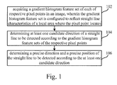
- step 102 a gradient histogram feature set of each of respective pixel points in an image is acquired, wherein the gradient histogram feature set is configured to reflect straight line characteristics of a local area where the pixel point locates.
- step 104 at least one candidate direction of a straight line to be detected is determined according to the gradient histogram feature sets of the respective pixel points.
- step 106 a precise direction and a precise position of the straight line to be detected are determined according to the at least one candidate direction.
- the method for detecting the straight line by acquiring the gradient histogram feature set of each of the respective pixel points in the image; determining the at least one candidate direction of the straight line to be detected according to the gradient histogram feature sets of the respective pixel points; and then determining the a precise direction and a precise position of the straight line to be detected according to the at least one candidate direction, wherein the gradient histogram feature set is configured to reflect the straight line characteristics of the local area where the pixel point locates, the problem in the related art that the method for detecting the straight line may cause the straight line broken and the detection result inaccurate when the edge strength is weak or there are noise interferences existing is solved.
- the method for detecting the straight line Compared to the related method for detecting a straight line in the Background, the method for detecting the straight line provided by the present embodiment neither uses Hough Transform nor binaries the image, thus avoiding the influences of errors caused by binarization, and increasing the accuracy of the detection of the straight line.
- Fig. 2A is a flow chart showing a method for detecting a straight line, according to another exemplary embodiment.
- the present embodiment illustrates the method for detecting the straight line as to be applied in the electronic apparatus.
- the method for detecting the straight line may include the following steps.
- step 201 a grayscale image of an image is generated.
- the electronic apparatus grays an collected image at first to generate a grayscale image of the image.
- the grayscale is classified into 256 levels, a gray value of any pixel point (i, j) is I(i, j) ⁇ [0, 255].
- step 202 a gradient histogram feature set of respective pixel points in the image is acquired.
- the electronic apparatus acquires a gradient histogram feature set of each of the respective pixel points in the image, the gradient histogram feature set is configured to reflect straight line characteristics of a local area where the pixel point locates.
- This step may include the following two sub-steps.
- a direction gradient set g(i, j) of the pixel point is calculated.
- a direction gradient set of one pixel point includes direction gradient values of the pixel point in K directions, and a direction gradient value of the pixel point in any direction refers to an absolute value of a difference between a gray value of the pixel point and a gray value of an adjacent pixel point in the direction, K ⁇ 2.
- a value of K is preset according to actual requirements, the greater the value of K is, the more precise the result of the detection of the straight line is. In order to reduce calculated amount, the value of K is 4 or 8 in a normal circumstance.
- a size of the image I is M*N (M and N respectively represent a number of pixel points in a horizontal direction and a vertical direction of the image I), M ⁇ 1, N ⁇ 1.
- M and N respectively represent a number of pixel points in a horizontal direction and a vertical direction of the image I
- M ⁇ 1, N ⁇ 1 M ⁇ 1, N ⁇ 1.
- a direction gradient set corresponding to the pixel point is g (i, j).
- the 4 directions are respectively directions at angles of 0° , 45°, 90° and 135° to the horizontal direction, and direction gradient values of the pixel point (i, j) in the 4 directions are respectively recorded as g 0 (i, j), g 45 (i, j), g 90 (i, j) and g 135 (i, j).
- g i ⁇ j g 0 i ⁇ j , g 45 i ⁇ j , g 90 i ⁇ j , g 135 i ⁇ j , wherein
- g 90 (i,j)
- g 135 (i, j)
- I(i, j) represents the gray value of the pixel point (i, j), I(i, j) ⁇ [0, 255].
- boundary pixel points in the image may not be taken into consideration, wherein the boundary pixel points refer to pixel points at four edges of the periphery of the image, for example, the pixel points contained in the region outside a black frame 21 in Fig. 2B .
- a gradient histogram feature set h(i, j) of the pixel point is calculated according to the direction gradient set g(i, j) of the pixel point.
- the electronic apparatus calculates a gradient histogram feature set h(i, j) of the pixel point according to the direction gradient set g(i, j) of the pixel point.
- the gradient histogram feature set h(i, j) of the pixel pint reflects straight line characteristics of a local area where the pixel point locates, the straight line characteristics include whether a straight line to be detected exists and a first kind or all of the two kinds of approximate directions of the straight line to be detected within the local area where the pixel point locates.
- the approximate direction of the straight line to be detected refers to the direction that the straight line to be detected approaches. For example, if the direction that the straight line to be detected approaches is a neighborhood range of 45°, the approximate direction of the straight line to be detected is 45°.
- the above-described second sub-step may further include the following several sub-steps.
- the electronic apparatus respectively calculates local gradient values h k (i,j) of the pixel point in the K directions, and k represents a direction.
- a local gradient value h k (i,j) of the pixel point (i, j) in k direction is equal to a sum of direction gradient values of all pixel points in the k direction within the local area where the pixel point locates.
- R is an average radius
- the value of R also decides a range of the local area 22 where the pixel point (i, j) locates, and a number of pixel points contained in the local area 22 where the pixel point (i, j) locates is equal to (2R+1)*(2R+1).
- the electronic apparatus calculates an average gradient value h norm (i, j) of the pixel point.
- the average gradient value h norm (i, j) is equal to extraction of a root of a sum of squares of the respective local gradient values h k (i,j) of the pixel point.
- h norm i ⁇ j ⁇ l ⁇ 0 ⁇ 45 ⁇ 90 ⁇ 135 h l i ⁇ j ⁇ 2 .
- the local gradient value h k (i,j) is divided by the average gradient value h norm (i, j) to obtain a gradient histogram feature h k (i, j) of the pixel point in the k direction.
- the electronic apparatus divides the local gradient value h k (i,j) by the average gradient value h norm (i, j) to obtain the gradient histogram feature h k (i, j) of the pixel point in the k direction.
- h k i ⁇ j h k i ⁇ j ⁇ / h norm i ⁇ j , k ⁇ 0 ⁇ 45 ⁇ 90 ⁇ 135 .
- a set of gradient histogram features in the K directions is determined as the gradient histogram feature set h(i, j) of the pixel point.
- the electronic apparatus determines a set of gradient histogram features in the K directions as the gradient histogram feature set h(i, j) of the pixel point.
- the gradient histogram feature set of the pixel point (i, j) is h(i, j), and the gradient histogram feature set h(i, j) includes gradient histogram features of the pixel point (i, j) in the K directions.
- h i ⁇ j h 0 i ⁇ j , h 45 i ⁇ j , h 90 i ⁇ j , h 135 i ⁇ j .
- the predetermined average value T norm reflects an overall gradient state of the local area where the pixel point locates in various directions, and when h norm (i, j) is rather small, it means that the edge strength within the local area is weak, the change of the gray values between adjacent pixel points may be caused by the factors such as noises or light illumination, rather than by an existed straight line to be detected within the local area. Accordingly, when h norm (i, j) is smaller than the predetermined average value T norm , the respective gradient histogram features in the gradient histogram feature set h(i, j) of the pixel point are set to be zero.
- step 203 at least one candidate direction of the straight line to be detected is determined according to the gradient histogram feature sets of the respective pixel points.
- the electronic apparatus determines at least one candidate direction of the straight line to be detected according to the gradient histogram feature sets of the respective pixel points.
- This step may include the following several sub-steps.
- a direction corresponding to a gradient histogram feature having a maximum value in the gradient histogram feature set is selected as a main direction of the local area where the pixel point locates.
- step 202 it has been introduced that the greater the value of h k (i, j) is, the more obvious, as indicated, the changes of the gray values of the respective pixel points in the k direction are, and there may be very likely sudden changes in the gray values. Based on this, it can be speculated that the direction perpendicular to the k direction is the approximate direction of the straight line to be detected.
- the electronic apparatus selects a direction corresponding to a gradient histogram feature having a maximum value in the gradient histogram feature set h(i, j) as a main direction of the local area where the pixel point locates, and the main direction is proximately perpendicular to the direction of the straight line in the local area.
- the electronic apparatus After determining a main direction of the local area where each pixel point in the image locates, the electronic apparatus carries out statistics of a vote number of the main directions of the local areas where the respective pixel points locate in the K directions for the whole graph.
- the statistical result may be that a of the main directions of the local area where the pixel point locates are 0°, b of the main direction of the local area where the pixel point locates are 45°, c of the main direction of the local area where the pixel point locates are 90°, and d of the main directions of the local area where the pixel point locates are 135°, wherein a, b, c and d are respectively vote numbers in four directions after statistics of the integral graph is carried out, and it is assumed that b>a>c>d.
- a direction perpendicular to a direction having a vote number that exceeds a vote threshold is selected as the candidate directions of the straight line to be detected.
- the electronic apparatus After carrying out statistics of vote numbers of the main directions of the local areas where the respective pixel points locate in the K directions, the electronic apparatus detects whether the vote numbers in various directions are greater than the vote threshold.
- a value of the vote threshold may be set by an overall consideration of factors such as a size of the image, data processing capability of the electronic apparatus and requirements for detection precision of the straight line.
- the electronic apparatus selects at least one direction having the vote number that exceeds the vote threshold, and uses a direction perpendicular to the selected direction as the candidate direction of the straight line to be detected. Since the direction having the vote number that exceeds the vote threshold reflects a main direction of one of the respective local areas in the image, and the main directions of the respective local areas are proximately perpendicular to the straight line in the image, thus it is required to select the direction perpendicular to the direction having the vote number that exceeds the vote threshold as a candidate direction of the straight line to be detected.
- one to two directions may be selected from the K directions as the candidate directions of the straight line to be detected.
- the electronic apparatus finally determines the precise direction and the precise position of the straight line to be detected by calculating and analyzing in a coarse-scale and a fine-scale.
- step 204 for each of the candidate directions, at least one scanning line parallel to the candidate direction is generated.
- the electronic apparatus For each of the candidate directions, the electronic apparatus generates at least one scanning line parallel to the candidate direction. Referring to Fig. 2C , a straight line L in an image having a size of M*N is shown in Fig. 2C . After the step 201 to the step 203, it can be determined that the candidate direction of the straight line to be detected is 135°. Scanning lines 26 in the direction of 135° are full of the entire image, a distance between adjacent scanning lines 26 may be set by an overall consideration of factors such as the size of the image, the data processing probability of the electronic apparatus and the requirements for detection precision of the straight line.
- step 205 a matching distance of each scanning line is respectively calculated.
- the electronic apparatus respectively calculates a matching distance of each scanning line, and the matching distance of the scanning line is configured to reflect a degree of proximity of the scanning line to the straight line to be detected.
- this step includes the following several sub-steps.
- n sample points are acquired by sampling on the scanning line, and n ⁇ 1.
- the electronic apparatus For each scanning line, the electronic apparatus acquires n sample points by sampling on the scanning line, and n ⁇ 1. Alternatively, the electronic apparatus acquires n sample points by evenly sampling on each scanning line. Referring to Fig. 2C , in the present embodiment, it is assumed that the electronic apparatus acquires 10 sample points 27 by evenly sampling on each scanning line.
- a matching distance between a gradient histogram feature set for each of the respective sample points and a template gradient histogram feature set in a direction perpendicular to the candidate direction is calculated.
- the electronic apparatus calculates a matching distance between a gradient histogram feature set for each of the respective sample points and a template gradient histogram feature set in a direction perpendicular to the candidate direction.
- the electronic apparatus has acquired the gradient histogram feature set of the respective pixel points in the image.
- the electronic apparatus looks up and acquires the gradient histogram feature set of the respective sample points from the gradient histogram feature set of the respective pixel points according to the coordinates of the respective sample points.
- the template gradient histogram feature set is Templates, s ⁇ ⁇ 0, 45, 90, 135 ⁇ .
- Template 45 ⁇ 0, 1, 0, 0 ⁇ ;
- Template 90 ⁇ 0, 0, 1, 0 ⁇ ;
- Template 135 ⁇ 0, 0, 0, 1 ⁇ .
- the acquired n sample points are respectively (x 0 , y0), (x 1 , y 1 ), ...,(x i , y i ),...,(x n-1 ,y n-1 ).
- the electronic apparatus sums the matching distances of the n sample points to obtain the matching distance of the scanning line.
- step 206 the scanning line having a minimum matching distance is selected as a candidate straight line.
- the electronic apparatus After calculating the matching distances of the respective scanning lines, the electronic apparatus selects the scanning line having a minimum matching distance as a candidate straight line.
- the scanning line that passes through two points O and P is the scanning line having the minimum matching distance, i.e. the scanning line that passes through the two points O and P is selected as the candidate straight line.
- a proximate position of the straight line L to be detected in the image can be roughly determined. Then, the precise direction and the precise position of the straight line L to be detected in the image are finally determined by calculating and analyzing in fine scale in the following step 207.
- step 207 the specific direction and position of the straight line to be detected are determined according to the candidate straight line.
- the electronic apparatus determines the specific direction and position of the straight line to be detected according to the candidate straight line.
- This step may include the following several sub-steps.
- a rectangle region having a predetermined size is generated.
- the electronic apparatus generates a rectangle region having a predetermined size by using the candidate straight line as a central axis.
- two points O and P may be selected on the candidate straight line
- the length of the line segment OP is the length of the rectangle region.
- the length of the line segment OP should be selected as long as possible.
- vertical line segments AB and CD that respectively pass through the two points O and P of the candidate straight line are made, wherein the point O is a midpoint of the line segment AB and the point P is a midpoint of the line segment CD.
- Lengths of the line segments AB and CD are widths of the rectangle region. In practical applications, the lengths of the line segments AB and CD may be selected to be twice as the distance between the adjacent scanning lines.
- u points and v points are respectively selected, and every two points on the two sides are connected to obtain u*v line segments, u ⁇ 1, v ⁇ 1.
- the electronic apparatus respectively calculates a matching distance of each line segment among the u*v line segments.
- the matching distance of the line segment is configured to reflect a degree of proximity of the line segment to the straight line to be detected. The smaller the matching distance of the line segment is, the more, as indicated, the line segment approaches the straight line to be detected; on the contrary, the greater the matching distance of the line segment is, the more, as indicated, the line segment offsets from the straight line to be detected.
- the template gradient histogram feature set of the line segment in the actual direction may allocate sizes of respective gradient histogram features in the template gradient histogram feature set according to projection distances of the line segment in K directions by adding weights.
- a straight line to which a line segment having a minimum matching distance belongs is selected as the straight line to be detected.
- the electronic apparatus After calculating the matching distances of the respective line segments, the electronic apparatus selects a straight line to which a line segment having a minimum matching distance belongs as the straight line to be detected.
- the electronic apparatus may select greater values of u and v, so as to more precisely determine the precise direction and the position of the straight line to be detected.
- step 201 to step 207 the detection of the straight line in the image is introduced in detail.
- the method for detecting the straight line provided by the present embodiment neither uses Hough Transform nor binaries the image, thus avoiding the influences of errors caused by binarization, and increasing the accuracy of the detection of the straight line.
- how to detect the rectangle in the image on the basis of the method for detecting the straight line provided by the present embodiment will be introduced in detail.
- step 208 for any straight line to be detected, whether a second straight line to be detected that meets a first predetermined condition exists in the image is detected.
- the electronic apparatus detects whether a second straight line to be detected that meets a first predetermined condition exists in the image.
- the method used by the electronic apparatus to detect and acquire the second straight line to be detected from the image may refer to the method for detecting the straight line involved in the step 201 to the step 207. After the second straight line to be detected is detected and acquired, whether each of the second straight lines to be detected meets the first predetermined condition is continued to be detected.
- the first predetermined condition includes that the second straight line to be detected and the straight line to be detected have an intersection point within the image and an angle therebetween smaller than an angle threshold value.
- angle ⁇
- the angle threshold value may be coarsely set, whch is for example, 3 radians.
- step 209 if a detection result is that the second straight line to be detected that meets the first predetermined condition exists, the second straight line to be detected is added to a candidate straight line set.
- the electronic apparatus adds the second straight line to be detected to the candidate straight line set of the straight line to be detected.
- the candidate straight line set of the straight line to be detected includes all of the second straight lines to be detected that meet the first predetermined condition.
- step 210 for any two of the second straight lines to be detected in the candidate straight line set, whether a third straight line to be detected that meets a second predetermined condition exists is detected.
- the electronic apparatus detects whether a third straight line to be detected that meets the second predetermined condition exists.
- the second predetermined condition includes that the third straight line to be detected is different from the straight line to be detected, and the third straight line to be detected intersects both of the two second straight lines to be detected with two intersection points both within the image.
- step 211 if a detection result is that the third straight line to be detected that meets the second predetermined condition exists, a quadrangle composed of the straight line to be detected, the two second straight lines to be detected and the third straight line to be detected is added to a candidate rectangle set.
- the electronic apparatus adds a quadrangle composed of the straight line to be detected, the two second straight lines to be detected and the third straight line to be detected to the candidate rectangle set.
- the candidate rectangle set comprises all quadrangles that are likely to become rectangles to be detected.
- step 212 for each quadrangle in the candidate rectangle set, a matching distance of the rectangle is calculated.
- the electronic apparatus calculates a matching distance of the rectangle.
- the matching distance of the quadrangle is configured to reflect a degree of proximity of the quadrangle to a rectangle to be detected, and the smaller the matching distance of the rectangle is, the more, as indicated, the rectangle approaches the rectangle to be detected, on the contrast, the greater the matching distance of the rectangle is, the more, as indicated, the rectangle offsets from the rectangle to be detected.
- the matching distance of the rectangle is equal to a sum of matching distances of line segments corresponding to four sides of the rectangle.
- the matching distance of the line segment corresponding to any side of the rectangle may refer to the method in the third sub-step in the above-descried step 207, which will not be described repeatedly herein.
- step 213 a rectangle having a minimum matching distance or a matching distance smaller than a matching threshold value is determined as the rectangle to be detected.
- the electronic apparatus determines a rectangle having a minimum matching distance or a matching distance smaller than a matching threshold value as the rectangle to be detected.
- the method for detecting the straight line by acquiring the gradient histogram feature set of each of the respective pixel points in the image. determining the at least one candidate direction of the straight line to be detected according to the gradient histogram feature sets of the respective pixel points; and then determining the precise direction and the position of the straight line to be detected according to the at least one candidate direction, wherein the gradient histogram feature set is configured to reflect the straight line characteristics of the local area where the pixel point locates, the problem in the related art that the method for detecting the straight line may cause the straight line broken and the detection result inaccurate when the edge strength is weak or there are noise interferences existing is solved.
- the method for detecting the straight line Compared to the related method for detecting a straight line in the Background, the method for detecting the straight line provided by the present embodiment neither uses Hough Transform nor binaries the image, thus avoiding the influences of errors caused by binarization, and increasing the accuracy of the detection of the straight line.
- the present embodiment further provides a method for detecting a rectangle on the basis of the detection of the straight line. After all rectangles that are likely to become the rectangles to be detected are constructed, by calculating the matching distances of the respective rectangles respectively, and determining the rectangle having the minimum matching distance or the matching distance smaller than the matching threshold value as the rectangle to be detected, the detection of a rectangle shape such as a card, a receipt or a book in the image is realized, and the actual application range of the method for detecting the straight line and the method for detecting the rectangle provided by the present disclosure is broadened.
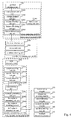
- Fig. 3 is a diagram showing a device for detecting a straight line, according to an exemplary embodiment.
- the device for detecting the straight line may be implemented to be all or a part of an electronic apparatus by software, hardware or a combination thereof.
- the device for detecting the straight line may include a feature acquiring module 310, a candidate determining module 320 and a precision determining module 330.
- the feature acquiring module 310 is configured to acquire a gradient histogram feature set of each of the respective pixel points in an image, wherein the gradient histogram feature set is configured to reflect straight line characteristics of a local area where the pixel point locates.
- the candidate determining module 320 is configured to determine at least one candidate direction of a straight line to be detected according to the gradient histogram feature sets of the respective pixel points.
- the precision determining module 330 is configured to determine a precise direction and a precise position of the straight line to be detected according to the at least one candidate direction.
- the device for detecting the straight line by acquiring the gradient histogram feature set of each of the respective pixel points in the image; determining the at least one candidate direction of the straight line to be detected according to the gradient histogram feature sets of the respective pixel points; and then determining the a precise direction and a precise position of the straight line to be detected according to the at least one candidate direction, wherein the gradient histogram feature set is configured to reflect the straight line characteristics of the local area where the pixel point locates, the problem in the related art that the method for detecting the straight line may cause the straight line broken and the detection result inaccurate when the edge strength is weak or there are noise interferences existing is solved.
- the method for detecting the straight line provided by the present embodiment neither uses Hough Transform nor binaries the image, thus avoiding the influences of errors caused by binarization sufficiently, and increasing the accuracy of the detection of the straight lined.
- Fig. 4 is a diagram showing a device for detecting a straight line, according to another exemplary embodiment.
- the device for detecting the straight line may be implemented to be all or a part of an electronic apparatus by software, hardware or a combination thereof.
- the device for detecting the straight line may include a feature acquiring module 310, a candidate determining module 320, a precision determining module 330, a first detecting module 332, a straight line candidate module 334, a second detecting module 336, a rectangle candidate module 338, a match calculating module 340 and a rectangle determining module 342.
- the feature acquiring module 310 is configured to acquire a gradient histogram feature set of each of the respective pixel points in an image, wherein the gradient histogram feature set is configured to reflect straight line characteristics of a local area where the pixel point locates.
- the feature acquiring module 310 includes a gradient calculating unit 310a and a feature calculating unit 310b.
- the gradient calculating unit 310a is configured to, for each pixel point (i, j) of the respective pixel points, calculate a direction gradient set g(i, j) of the pixel point, wherein the direction gradient set g(i, j) includes direction gradient values of the pixel point in K directions.
- the direction gradient value of the pixel point in any direction refers to an absolute value of a difference between a gray value of the pixel point and a gray value of an adjacent pixel point in the direction, K ⁇ 2.
- the feature calculating unit 310b is configured to calculate a gradient histogram feature set h(i, j) of the pixel point according to the direction gradient set g(i, j) of the pixel point.
- the feature calculating unit 310b includes a local gradient sub-unit 310b1, an average gradient sub-unit 310b2, an average detecting sub-unit 310b3, a feature zero setting sub-unit 310b4, a feature calculating sub-unit 310b5 and a feature determining sub-unit 310b6.
- the local gradient sub-unit 310b1 is configured to respectively calculate local gradient values h k (i,j) of the pixel point in the K directions, wherein a local gradient value h k (i,j) in k direction is equal to a sum of the direction gradient values of all pixel points in the k direction within the local area where the pixel point locates, and wherein k represents a direction.
- the average gradient sub-unit 310b2 is configured to calculate an average gradient value h norm (i, j) of the pixel point, wherein the average gradient value h norm (i, j) is equal to extraction of a root of a sum of squares of the respective local gradient values h k i,j) of the pixel point.
- the average detecting sub-unit 310b3 is configured to, for each pixel point (i, j) of the respective pixel points, detect whether the average gradient value h norm (i, j) is smaller than a predetermined average value T norm .
- the feature zero setting sub-unit 310b4 is configured to set the respective gradient histogram features in the gradient histogram feature set h(i, j) of the pixel point to zero, if a detection result is that the average gradient value h norm (i, j) is smaller than the predetermined average value T norm .
- the feature calculating sub-unit 310b5 is configured to divide the local gradient value h k (i,j) by the average gradient value h norm (i, j) to obtain a gradient histogram feature h k (i, j) of the pixel point in the k direction
- the feature determining sub-unit 310b6 is configured to determine a set of gradient histogram features in the K directions as the gradient histogram feature set h(i, j) of the pixel point.
- the candidate determining module 320 is configured to determine at least one candidate direction of the straight line to be detected according to the gradient histogram feature sets of the respective pixel points.
- the candidate determining module 320 includes a direction selecting unit 320a, a vote statistic unit 320b and a candidate selecting unit 320c.
- the direction selecting unit 320a is configured to, for each of the respective pixel points, select a direction corresponding to a gradient histogram feature having a maximum value in the gradient histogram feature set as a main direction of the local area where the pixel point locates.
- the vote statistic unit 320b is configured to carry out statistics of vote numbers of the main directions of the local areas where the respective pixel points locate in the K directions.
- the candidate selecting unit 320c is configured to select a direction perpendicular to a direction having a vote number that exceeds a vote threshold as a candidate direction of the straight line to be detected.
- the precision determining module 330 is configured to determine the precise direction and the precise position of the straight line to be detected according to the at least one candidate direction.
- the precision determining module 330 includes a scan generating unit 330a, a scan matching unit 330b, a scan selecting unit 330c and a precision determining unit 330d.
- the scan generating unit 330a is configured to, for each of the candidate directions, generate at least one scanning line parallel to the candidate direction.
- the scan matching unit 330b is configured to respectively calculate a matching distance of each scanning line, wherein the matching distance of the scanning line is configured to reflect a degree of proximity of the scanning line to the straight line to be detected.
- the scan matching unit 330b includes a sample acquiring sub-unit 330b1, a sample matching sub-unit 330b2 and a sample summing sub-unit 330b3.
- the sample acquiring sub-unit 330b1 is configured to, for each of the scanning lines, acquiring n sample points by sampling on the scanning line, n ⁇ 1.
- the sample matching sub-unit 330b2 is configured to calculate a matching distance between a gradient histogram feature set for each of the respective sample points and a template gradient histogram feature set in a direction perpendicular to the candidate direction.
- the sample summing sub-unit 330b3 is configured to sum matching distances of the n sample points to obtain the matching distance of the scanning line.
- the scan selecting unit 330c is configured to select the scanning line having a minimum matching distance as a candidate straight line.
- the precision determining unit 330d is configured to determine the precise direction and the precise position of the straight line to be detected according to the candidate straight line.
- the precision determining unit 330d includes a rectangle generating sub-unit 330d1, a line segment generating sub-unit 330d2, a line segment matching sub-unit 330d3 and a line segment selecting sub-unit 330d4.
- the rectangle generating sub-unit 330d1 is configured to generate a rectangle region having a predetermined size by using the candidate straight line as a central axis.
- the line segment generating sub-unit 330d2 is configured to respectively select u points and v points on two sides of the rectangle region perpendicular to the candidate straight line, and connect every two points on the two sides to obtain u*v line segments, u ⁇ 1, v ⁇ 1.
- the line segment matching sub-unit 330d3 is configured to respectively calculate a matching distance of each line segment among the u*v line segments, wherein the matching distance of the line segment is configured to reflect a degree of proximity of the line segment to the straight line to be detected.
- the line segment selecting sub-unit 330d4 is configured to select a straight line to which a line segment having a minimum matching distance belongs as the straight line to be detected.
- the first detecting module 332 is configured to, for any straight line to be detected, detect whether a second straight line to be detected that meets a first predetermined condition exists in the image, wherein the first predetermined condition includes that the second straight line to be detected and the straight line to be detected have an intersection point within the image and an angle there between smaller than an angle threshold value.
- the straight line candidate module 334 is configured to add the second straight line to be detected to a candidate straight line set, if a detection result is that the second straight line to be detected that meets the first predetermined condition exists.
- the second detecting module 336 is configured to, for any two of the second straight lines to be detected in the candidate straight line set, detect whether a third straight line to be detected that meets a second predetermined condition exists, wherein the second predetermined condition includes that the third straight line to be detected is different from the straight line to be detected, and the third straight line to be detected intersects both of the two second straight lines to be detected with two intersection points both within the image.
- the rectangle candidate module 338 is configured to add a quadrangle composed of the straight line to be detected, the two second straight lines to be detected and the third straight line to be detected to a candidate rectangle set, if a detection result is that the third straight line to be detected that meets the second predetermined condition exists.
- the match calculating module 340 is configured to, for each quadrangle in the candidate rectangle set, calculate a matching distance of the rectangle, wherein the matching distance of the quadrangle is configured to reflect a degree of proximity of the quadrangle to a rectangle to be detected, and the matching distance of the quadrangle is equal to a sum of matching distances of line segments corresponding to four sides of the quadrangle.
- the rectangle determining module 342 is configured to determine a quadrangle having a minimum matching distance or a matching distance smaller than a matching threshold value as the rectangle to be detected.
- the device for detecting the straight line by acquiring the gradient histogram feature set of each of the respective pixel points in the image; determining the at least one candidate direction of the straight line to be detected according to the gradient histogram feature sets of the respective pixel points; and then determining the a precise direction and a precise position of the straight line to be detected according to the at least one candidate direction, wherein the gradient histogram feature set is configured to reflect the straight line characteristics of the local area where the pixel point locates, the problem in the related art that the method for detecting the straight line may cause the straight line broken and the detection result inaccurate when the edge strength is weak or there are noise interferences existing is solved.
- the method for detecting the straight line provided by the present embodiment neither uses Hough Transform nor binaries the image, thus avoiding the influences of errors caused by binarization sufficiently, and increasing the accuracy of the detection of the straight line.
- the present embodiment further provides a device for detecting a rectangle on the basis of the detection of the straight line. After all rectangles that are likely to become the rectangles to be detected are constructed, by calculating the matching distances of the respective rectangles respectively, and determining the rectangle having the minimum matching distance or the matching distance smaller than the matching threshold value as the rectangle to be detected, the detection of a rectangle shape such as a card, a receipt or a book in the image is realized, and the actual application range of the device for detecting the straight line and the device for detecting the rectangle provided by the present disclosure is broadened.
- the device for detecting the straight line provided in the above embodiments detects the straight line in the image
- the division of the modules with functions as above is described only for illustration. In actual applications, the above functions may be implemented by different modules as needed. That is, the internal structure of the device is divided into different modules, to realize all or a part of the above-described functions.
- the devices for detecting the straight line provided by the above embodiments belong to the same inventive concept as that of the embodiments for the methods for detecting the straight line, and the specific implementing processes thereof may be found in the embodiments of the methods, which are not described repeatedly.
- Fig. 5 is a block diagram of a device 500 which is configured to detect a straight line, according to an exemplary embodiment.
- the device 500 may be a mobile phone, a computer, a digital broadcast terminal, a messaging device, a gaming console, a tablet, a medical device, exercise equipment, a personal digital assistant and the like.
- the device 500 may include one or more of the following components: a processing component 502, a memory 504, a power component 506, a multimedia component 508, an audio component 510, an input/output (I/O) interface 512, a sensor component 514, and a communication component 516.
- the processing component 502 usually controls overall operations of the device 500, such as the operations associated with display, telephone calls, data communications, camera operations, and recording operations.
- the processing component 502 may include one or more processors 520 to execute instructions to perform all or part of the steps in the above described methods.
- the processing component 502 may include one or more modules which facilitate the interaction between the processing component 502 and other components.
- the processing component 502 may include a multimedia module to facilitate the interaction between the multimedia component 508 and the processing component 502.
- the memory 504 is configured to store various types of data to support the operation of the device 500. Examples of such data include instructions for any application or method operated on the device 500, contact data, phonebook data, messages, pictures, videos, etc.
- the memory 504 may be implemented using any type of volatile or non-volatile memory device or combination thereof, such as a static random access memory (SRAM), an electrically erasable programmable read-only memory (EEPROM), an erasable programmable read-only memory (EPROM), a programmable read-only memory (PROM), a read-only memory (ROM), a magnetic memory, a flash memory, a magnetic or optical disk.
- SRAM static random access memory
- EEPROM electrically erasable programmable read-only memory
- EPROM erasable programmable read-only memory
- PROM programmable read-only memory
- ROM read-only memory
- magnetic memory a magnetic memory
- flash memory a flash memory
- magnetic or optical disk a magnetic or optical disk.
- the power component 506 provides power to various components of the device 500.
- the power component 506 may include a power management system, one or more power sources, and other components associated with the generation, management, and distribution of power in the device 500.
- the multimedia component 508 includes a screen providing an output interface between the device 500 and the user.
- the screen may include a liquid crystal display (LCD) and a touch panel (TP). If the screen includes the touch panel, the screen may be implemented as a touch screen to receive input signals from the user.
- the touch panel includes one or more touch sensors to sense touches, slips, and gestures on the touch panel. The touch sensors may not only sense a boundary of a touch or slip action, but also sense a period of time and a pressure associated with the touch or slip action.
- the multimedia component 508 includes a front camera and/or a rear camera.
- the front camera and/or the rear camera may receive an external multimedia datum while the device 500 is in an operation mode, such as a photographing mode or a video mode.
- an operation mode such as a photographing mode or a video mode.
- Each of the front camera and the rear camera may be a fixed optical lens system or have focus and optical zoom capability.
- the audio component 510 is configured to output and/or input audio signals.
- the audio component 510 includes a microphone ("MIC") configured to receive an external audio signal when the device 500 is in an operation mode, such as a call mode, a recording mode, and a voice recognition mode.
- the received audio signal may be further stored in the memory 504 or transmitted via the communication component 516.
- the audio component 510 further includes a speaker to output audio signals.
- the I/O interface 512 provides an interface between the processing component 502 and peripheral interface modules, such as a keyboard, a click wheel, a button, and the like.
- the button may include, but not limited to, a home button, a volume button, a starting button, and a locking button.
- the sensor component 514 includes one or more sensors to provide status assessments of various aspects of the device 500. For instance, the sensor component 514 may detect an open/closed status of the device 500, relative positioning of components, e.g., the display and the keyboard, of the device 500, a change in position of the device 500 or a component of the device 500, a presence or absence of user contact with the device 500, an orientation or an acceleration/deceleration of the device 500, and a change in temperature of the device 500.
- the sensor component 514 may include a proximity sensor configured to detect the presence of nearby objects without any physical contact.
- the sensor component 514 may also include a light sensor, such as a CMOS or CCD image sensor, for use in imaging applications.
- the sensor component 514 may also include an accelerometer sensor, a gyroscope sensor, a magnetic sensor, a pressure sensor, or a temperature sensor.
- the communication component 516 is configured to facilitate communication, wired or wirelessly, between the device 500 and other devices.
- the device 500 can access a wireless network based on a communication standard, such as WiFi, 2G, or 3G, or a combination thereof.
- the communication component 516 receives a broadcast signal or broadcast associated information from an external broadcast management system via a broadcast channel.
- the communication component 516 further includes a near field communication (NFC) module to facilitate short-range communications.
- the NFC module may be implemented based on a radio frequency identification (RFID) technology, an infrared data association (IrDA) technology, an ultra-wideband (UWB) technology, a Bluetooth (BT) technology, and other technologies.
- RFID radio frequency identification
- IrDA infrared data association
- UWB ultra-wideband
- BT Bluetooth
- the device 500 may be implemented with one or more application specific integrated circuits (ASICs), digital signal processors (DSPs), digital signal processing devices (DSPDs), programmable logic devices (PLDs), field programmable gate arrays (FPGAs), controllers, micro-controllers, microprocessors, or other electronic components, for performing the above described methods.
- ASICs application specific integrated circuits
- DSPs digital signal processors
- DSPDs digital signal processing devices
- PLDs programmable logic devices
- FPGAs field programmable gate arrays
- controllers micro-controllers, microprocessors, or other electronic components, for performing the above described methods.
- non-transitory computer readable storage medium including instructions, such as included in the memory 504, executable by the processor 820 in the device 500, for performing the above-described methods.
- the non-transitory computer-readable storage medium may be a ROM, a random access memory (RAM), a CD-ROM, a magnetic tape, a floppy disc, an optical data storage device, and the like.
- a non-transitory computer readable storage medium when instructions in the storage medium are executed by the processor of the terminal device, the terminal device can execute a method for detecting a straight line, the method includes:
- the gradient histogram feature set is configured to reflect straight line characteristics of a local area where the pixel point locates
- the device by acquiring the gradient histogram feature set of each of the respective pixel points in the image; determining the at least one candidate direction of the straight line to be detected according to the gradient histogram feature sets of the respective pixel points; and then determining the a precise direction and a precise position of the straight line to be detected according to the at least one candidate direction, wherein the gradient histogram feature set is configured to reflect the straight line characteristics of the local area where the pixel point locates, the problem in the related art that the method for detecting the straight line may cause the straight line broken and the detection result inaccurate when the edge strength is weak or there are noise interferences existing is solved. Moreover, the method for detecting the straight line provided by the present embodiment neither uses Hough Transform nor binaries the image, thus avoiding the influences of errors caused by binarization sufficiently, and increasing the accuracy of the detection of the straight line.
- the electronic apparatus may typically be various handheld terminal apparatuses, such as a mobile phone, a personal digital assistant (PDA) and the like. Therefore, the scope of the present disclosure is not limited to a particular type of electronic apparatus.
- PDA personal digital assistant
- the method according to the present disclosure may be implemented as the computer program executed by CPU, and the computer program may be stored in the computer-readable storage medium.
- the computer program is executed by the CPU, the above functions defined in the methods of the present disclosure are performed.
- the above steps of the methods and the units of the system may also be implemented with a controller and a computer-readable storage device which stores computer programs that cause the controller to realize the above steps and functions of the units.
- the above mentioned computer-readable storage device may be a volatile memory or a nonvolatile memory, or may include the both.
- the nonvolatile memory may include a read only memory (ROM), a programmable ROM (PROM), an electrically programmable ROM (EPROM), an electrically erasable programmable ROM (EEPROM), or a flash memory.
- the volatile memory may include a random access memory (RAM) which may serve as an external cache RAM memory.
- the RAM may be of various forms, such as a synchronous RAM (DRAM), a dynamic RAM (DRAM), a synchronous DRAM (SDRAM), a double data rate SDRAM (DDR SDRAM), an enhanced SDRAM (ESDRAM), a synchronous link DRAM (SLDRAM) and a direct Rambus RAM (DRRAM).
- DRAM synchronous RAM
- DRAM dynamic RAM
- SDRAM synchronous DRAM
- DDR SDRAM double data rate SDRAM
- ESDRAM enhanced SDRAM
- SLDRAM synchronous link DRAM
- DRRAM direct Rambus RAM
- a general purpose processor may be a microprocessor.
- the processor may be any one of a conventional processor, a controller, a microcontroller, or a state machine.
- the processor may be implemented as combination of computing devices, such as combination of a DSP and a microprocessor, a plurality of microprocessors, one or more microprocessors in conjunction with a DSP core, or any other such configuration.
- the method and steps of the algorithm described in conjunction with the present disclosure may be directly contained in hardware, in a software module executed by a processor or in combination of the both.
- the software module may reside in a RAM memory, a flash memory, a ROM memory, an EPROM memory, an EEPROM memory, a registers, a hard disk, a removable disk, a CD-ROM, or any other storage medium known in the art.
- An exemplary storage medium is coupled to the processor such that the processor can read information from the storage medium or write information thereto.
- the storage medium may be integrated with the processor.
- the processor and the storage medium may reside in an ASIC which may reside in a user terminal.
- the processor and the storage medium may reside in a user terminal as discrete components.
- the above functions may be implemented in hardware, software, firmware, or any combination thereof. If implemented in software, the above functions may be stored in a computer readable medium as one or more instructions or codes, or transmitted through the computer readable medium.
- the computer readable medium includes computer storage medium and communication medium.
- the communication media includes any medium that may be used to transmit computer programs from one location to another location.
- the storage medium may be any available medium that is accessible by a general or special computer.
- the computer readable medium may include a RAM, a ROM, an EEPROM, a CD-ROM or other CD storage devices, disk storage device or other magnetic storage devices, or any other medium that may be used to carry or store the required program codes in a form of instructions or data structure and may be accessible by a general or special computer or a general or special processor.
- any connection may be appropriately called as a computer-readable medium.
- the disk and the optical disk includes a compression disk (CD), a laser disc, an optical disk, a digital versatile disc (DVD), a floppy disks, a blue-ray disk, among which the magnetic disk normally represents data magnetically, and the optical disk represents data optically by utilizing a laser.
- CD compression disk
- DVD digital versatile disc
- floppy disks a blue-ray disk
- the program may be stored in a computer readable storage medium, and the storage medium may be a read only storage, a magnetic disk or an optical disk, etc.
Abstract
Description
- The present disclosure generally relates to the field of image processing, and more particularly, to a method and a device for detecting a straight line.
- It is an important subject to detect a straight line and a geometrical shape in the field of image processing. In a real scene, since there are a large number of straight lines and geometrical shapes, it will be of great importance in image processing to realize methods for quickly and accurately detecting the straight lines and the geometrical shapes.
- The method for detecting the geometrical shapes is usually generated from the method for detecting the straight lines. In the related art, the method of Hough transform is usually used to detect the straight lines. The Hough transform defines a parameter space which has a dual relationship with an image, one straight line in the image corresponds to one point in the parameter space, and one point in the image corresponds to one sine curve in the parameter space. From the above corresponding relationship, it is known that several collinear points on one straight line in the image correspond to several sine curves which intersect at the same point in the parameter space. Based on this, a problem of detecting a straight line having maximum collinear points in the image is changed into a problem of detecting a peak point at which a number of sine curves that intersect at one point is maximum in the parameter space, and a straight line corresponding to the peak point is a straight line to be detected in the image.
- During the realization of this present disclosure, at least the following problems in the above manner are found by the inventor: in the above method for detecting the straight lines based on the Hough transform, since several collinear points need to be sampled in the image, the image needs to be binarized at first, namely, a binary image composed of black pixel points and white pixel points is obtained, and then several collinear points are sampled in the binary image. However, binarization of the image is sensitive to parameters, and it is only applicable for detecting a straight line which has strong edge strength, i.e. the straight line having a gray value which obviously differs from grey values of other regions in the image. Moreover, when the edge strength is weak or there are noise interferences, the straight line may be broken, and accuracy of the detection results will be significantly influenced.
- In order to solve the problem in the related art that the method for detecting the straight line may cause the straight line broken and the detection result inaccurate when the edge strength is weak or there are noise interferences, embodiments of the present disclosure provide a method and a device for detecting a straight line. The technical solutions are as follows.
- According to a first aspect of the embodiments of the present disclosure, there is provided a method for detecting a straight line, including:
- acquiring a gradient histogram feature set of each of respective pixel points in an image, wherein the gradient histogram feature set is configured to reflect straight line characteristics of a local area where the pixel point locates;
determining at least one candidate direction of a straight line to be detected according to the gradient histogram feature sets of the respective pixel points; and
determining a precise direction and a precise position of the straight line to be detected according to the at least one candidate direction.
Alternatively, the acquiring the gradient histogram feature set of the respective pixel points in the image includes: - for each pixel point (i, j) of the respective pixel points, calculating a direction gradient set g(i, j) of the pixel point, wherein the direction gradient set g(i, j) includes direction gradient values of the pixel point in K directions, and a direction gradient value of the pixel point in any direction refers to an absolute value of a difference between a gray value of the pixel point and a gray value of an adjacent pixel point in the direction, K≥2; and
- calculating a gradient histogram feature set h(i, j) of the pixel point according to the direction gradient set g(i, j) of the pixel point.
- Alternatively, the calculating the gradient histogram feature set h(i, j) of the pixel point according to the direction gradient set g(i, j) of the pixel point includes:
- respectively calculating local gradient values
hk (i,j) of the pixel point in the K directions, wherein a local gradient valuehk (i,j) in k direction is equal to a sum of direction gradient values of all pixel points in the k direction within the local area where the pixel point locates, and wherein k represents a direction; - calculating an average gradient value hnorm(i, j) of the pixel point, wherein the average gradient value hnorm(i, j) is equal to extraction of a root of a sum of squares of the respective local gradient values
hk (i,j) of the pixel point; - dividing the local gradient value
hk (i,j) by the average gradient value hnorm(i, j) to obtain a gradient histogram feature hk(i, j) of the pixel point in the k direction; and - determining a set of gradient histogram features in the K directions as the gradient histogram feature set h(i, j) of the pixel point.
- Alternatively, the method further includes:
- for each pixel point (i, j) of the respective pixel points, detecting whether the average gradient value hnorm (i, j) is smaller than a predetermined average value Tnorm; and
- if a detection result is that the average gradient value hnorm(i, j) is smaller than the predetermined average value Tnorm, setting the respective gradient histogram features in the gradient histogram feature set h(i, j) of the pixel point to zero.
- Alternatively, the determining the at least one candidate direction of the straight line to be detected according to the gradient histogram feature sets of the respective pixel points includes:
- for each of the respective pixel points, selecting a direction corresponding to a gradient histogram feature having a maximum value in the gradient histogram feature set as a main direction of the local area where the pixel point locates;
- carrying out statistics of vote numbers of the main directions of the local areas where the respective pixel points locate in the K directions; and
- selecting a direction perpendicular to a direction having a vote number that exceeds a vote threshold as a candidate direction of the straight line to be detected.
- Alternatively, the determining the precise direction and the position of the straight line to be detected according to the at least one candidate direction includes:
- for each of the candidate directions, generating at least one scanning line parallel to the candidate direction;
- respectively calculating a matching distance of each scanning line, wherein the matching distance of the scanning line is configured to reflect a degree of proximity of the scanning line to the straight line to be detected;
- selecting the scanning line having a minimum matching distance as a candidate straight line; and
- determining the a precise direction and a precise position of the straight line to be detected according to the candidate straight line.
- Alternatively, the respectively calculating the matching distance of each scanning line includes:
- for each of the scanning lines, acquiring n sample points by sampling on the scanning line, n≥1;
- calculating a matching distance between a gradient histogram feature set for each of the respective sample points and a template gradient histogram feature set in a direction perpendicular to the candidate direction; and
- summing matching distances of the n sample points to obtain the matching distance of the scanning line.
- Alternatively, the determining the precise direction and the position of the straight line to be detected according to the candidate straight line includes:
- generating a rectangle region having a predetermined size by using the candidate straight line as a central axis,;
- respectively selecting u points and v points on two sides of the rectangle region perpendicular to the candidate straight line, and connecting every two points on the two sides to obtain u*v line segments, u≥1, v≥1;
- respectively calculating a matching distance of each line segment among the u*v line segments, wherein the matching distance of the line segment is configured to reflect a degree of proximity of the line segment to the straight line to be detected; and
- selecting a straight line to which a line segment having a minimum matching distance belongs as the straight line to be detected.
- Alternatively, the method further includes:
- for any straight line to be detected, detecting whether a second straight line to be detected that meets a first predetermined condition exists in the image, wherein the first predetermined condition includes that the second straight line to be detected and the straight line to be detected have an intersection point within the image and an angle therebetween smaller than an angle threshold value;
- if a detection result is that the second straight line to be detected that meets the first predetermined condition exists, adding the second straight line to be detected to a candidate straight line set;
- for any two of the second straight lines to be detected in the candidate straight line set, detecting whether a third straight line to be detected that meets a second predetermined condition exists, wherein the second predetermined condition includes that the third straight line to be detected is different from the straight line to be detected, and the third straight line to be detected intersects both of the two second straight lines to be detected with two intersection points both within the image;
- if a detection result is that the third straight line to be detected that meets the second predetermined condition exists, adding a quadrangle composed of the straight line to be detected, the two second straight lines to be detected and the third straight line to be detected to a candidate rectangle set;
- for each quadrangle in the candidate rectangle set, calculating a matching distance of the rectangle, wherein the matching distance of the quadrangle is configured to reflect a degree of proximity of the quadrangle to a rectangle to be detected, and the matching distance of the quadrangle is equal to a sum of matching distances of line segments corresponding to four sides of the quadrangle; and
- determining a quadrangle having a minimum matching distance or a matching distance smaller than a matching threshold value as the rectangle to be detected.
- According to a second aspect of the embodiments of the present disclosure, there is provided a device for detecting a straight line, including:
- a feature acquiring module configured to acquire a gradient histogram feature set of each of respective pixel points in an image, wherein the gradient histogram feature set is configured to reflect straight line characteristics of a local area where the pixel point locates;
- a candidate determining module configured to determine at least one candidate direction of a straight line to be detected according to the gradient histogram feature sets of the respective pixel points; and
- a precision determining module configured to determine a precise direction and a precise position of the straight line to be detected according to the at least one candidate direction.
- Alternatively, the feature acquiring module includes a gradient calculating unit and a feature calculating unit, wherein
- the gradient calculating unit is configured to, for each pixel point (i, j) of the respective pixel points, calculate a direction gradient set g(i, j) of the pixel point, wherein the direction gradient set g(i, j) includes direction gradient values of the pixel point in K directions, and a direction gradient value of the pixel point in any direction refers to an absolute value of a difference between a gray value of the pixel point and a gray value of an adjacent pixel point in the direction, K≥2, and
- the feature calculating unit is configured to calculate a gradient histogram feature set h(i, j) of the pixel point according to the direction gradient set g(i, j) of the pixel point.
- Alternatively, the feature calculating unit includes a local gradient sub-unit, an average gradient sub-unit, a feature calculating sub-unit and a feature determining sub-unit, wherein
the local gradient sub-unit is configured to respectively calculate local gradient valueshk (i,j) of the pixel point in the K directions, wherein a local gradient valuehk (i,j) in k direction is equal to a sum of direction gradient values of all pixel points in the k direction within the local area where the pixel point locates, and wherein k represents a direction,
the average gradient sub-unit is configured to calculate an average gradient value hnorm(i, j) of the pixel point, wherein the average gradient value hnorm(i, j) is equal to extraction of a root of a sum of squares of the respective local gradient valueshk (i,j) of the pixel point,
the feature calculating sub-unit is configured to divide the local gradient valuehk (i,j) by the average gradient value hnorm(i, j) to obtain a gradient histogram feature hk(i, j) of the pixel point in the k direction, and
the feature determining sub-unit is configured to determine a set of gradient histogram features in the K directions as the gradient histogram feature set h(i, j) of the pixel point. - Alternatively, the device further includes an average detecting sub-unit and a feature zero setting sub-unit, wherein
the average detecting sub-unit is configured to, for each pixel point (i, j) of the respective pixel points, detect whether the average gradient value hnorm (i, j) is smaller than a predetermined average value Tnorm, and
the feature zero setting sub-unit is configured to set the respective gradient histogram features in the gradient histogram feature set h(i, j) of the pixel point to zero, if a detection result is that the average gradient value hnorm(i, j) is smaller than the predetermined average value Tnorm.
Alternatively, the candidate determining module includes a direction selecting unit, a vote statistic unit and a candidate selecting unit, wherein
the direction selecting unit is configured to, for each of the respective pixel points, select a direction corresponding to a gradient histogram feature having a maximum value in the gradient histogram feature set as a main direction of the local area where the pixel point locates,
the vote statistic unit is configured to carry out statistics of vote numbers of the main directions of the local areas where the respective pixel points locate in the K directions, and
the candidate selecting unit is configured to select a direction perpendicular to a direction having a vote number that exceeds a vote threshold as a candidate direction of the straight line to be detected. - Alternatively, the precision determining module includes a scan generating unit, a scan matching unit, a scan selecting unit and a precision determining unit, wherein
the scan generating unit is configured to, for each of the candidate directions, generate at least one scanning line parallel to the candidate direction,
the scan matching unit is configured to respectively calculate a matching distance of each scanning line, wherein the matching distance of the scanning line is configured to reflect a degree of proximity of the scanning line to the straight line to be detected,
the scan selecting unit is configured to select the scanning line having a minimum matching distance as a candidate straight line, and
the precision determining unit is configured to determine the a precise direction and a precise position of the straight line to be detected according to the candidate straight line. - Alternatively, the scan matching unit includes a sample acquiring sub-unit, a sample matching sub-unit and a sample summing sub-unit, wherein
the sample acquiring sub-unit is configured to, for each of the scanning lines, acquiring n sample points by sampling on the scanning line, n≥1,
the sample matching sub-unit is configured to calculate a matching distance between a gradient histogram feature set for each of the respective sample points and a template gradient histogram feature set in a direction perpendicular to the candidate direction, and
the sample summing sub-unit is configured to sum matching distances of the n sample points to obtain the matching distance of the scanning line. - Alternatively, the precision determining unit includes a rectangle generating sub-unit, a line segment generating sub-unit, a line segment matching sub-unit and a line segment selecting sub-unit, wherein
the rectangle generating sub-unit is configured to generate a rectangle region having a predetermined size by using the candidate straight line as a central axis,
the line segment generating sub-unit is configured to respectively select u points and v points on two sides of the rectangle region perpendicular to the candidate straight line, and connect every two points on the two sides to obtain u*v line segments, u≥1, v≥1,
the line segment matching sub-unit is configured to respectively calculate a matching distance of each line segment among the u*v line segments, wherein the matching distance of the line segment is configured to reflect a degree of proximity of the line segment to the straight line to be detected, and
the line segment selecting sub-unit is configured to select a straight line to which a line segment having a minimum matching distance belongs as the straight line to be detected. - Alternatively, the device further includes:
- a first detecting module configured to, for any straight line to be detected, detect whether a second straight line to be detected that meets a first predetermined condition exists in the image, wherein the first predetermined condition includes that the second straight line to be detected and the straight line to be detected have an intersection point within the image and an angle therebetween smaller than an angle threshold value;
- a straight line candidate module configured to add the second straight line to be detected to a candidate straight line set, if a detection result is that the second straight line to be detected that meets the first predetermined condition exists; and
- a second detecting module configured to, for any two of the second straight lines to be detected in the candidate straight line set, detect whether a third straight line to be detected that meets a second predetermined condition exists, wherein the second predetermined condition includes that the third straight line to be detected is different from the straight line to be detected, and the third straight line to be detected intersects both of the two second straight lines to be detected with two intersection points both within the image;
- a rectangle candidate module configured to add a quadrangle composed of the straight line to be detected, the two second straight lines to be detected and the third straight line to be detected to a candidate rectangle set, if a detection result is that the third straight line to be detected that meets the second predetermined condition exists;
- a match calculating module configured to, for each quadrangle in the candidate rectangle set, calculate a matching distance of the rectangle, wherein the matching distance of the quadrangle is configured to reflect a degree of proximity of the quadrangle to a rectangle to be detected, and the matching distance of the quadrangle is equal to a sum of matching distances of line segments corresponding to four sides of the quadrangle; and
- a rectangle determining module configured to determine a quadrangle having a minimum matching distance or a matching distance smaller than a matching threshold value as the rectangle to be detected.
- According to a third aspect of the embodiments of the present disclosure, there is provided a computer program, which when executing on a processor of a device for detecting a straight line, performs a method according to any one described as above.
- The technical solutions provided by the embodiments of the present disclosure may include the following advantageous effects.
- By acquiring the gradient histogram feature set of each of respective pixel points in an image; determining at least one candidate direction of a straight line to be detected according to the gradient histogram feature sets of the respective pixel points; and then determining a precise direction and a precise position of the straight line to be detected according to the at least one candidate direction, wherein the gradient histogram feature set is configured to reflect straight line characteristics of a local area where the pixel point locates, the problem in the related art that the method for detecting the straight line may cause the straight line broken and the detection result inaccurate when the edge strength is weak or there are noise interferences existing is solved. Compared to the related method for detecting a straight line in the Background, the method for detecting the straight line provided by the present embodiment neither uses Hough Transform nor binaries the image, thus avoiding the influences of errors caused by binarization, and increasing the accuracy of the detection of the straight line.
- It is to be understood that both the foregoing general description and the following detailed description are exemplary only and are not restrictive of the present disclosure.
- The accompanying drawings herein, which are incorporated in and constitute a part of this specification, illustrate embodiments consistent with the invention and, together with the description, serve to explain the principles of the invention.
- In order to clearly explain the embodiments of the present disclosure, hereinafter, the introduction to the drawings required to be used in the depiction of the embodiments will be given simply. It is apparent that the following drawings only illustrate some of the embodiments of the present disclosure, and the person skilled in the art could obtain other drawings based on these drawings without inventive labor.
-
Fig. 1 is a flow chart showing a method for detecting a straight line, according to an exemplary embodiment; -
Fig. 2A is a flow chart showing a method for detecting a straight line, according to another exemplary embodiment; -
Fig. 2B is a schematic view involved in a feature calculating process of a method for detecting a straight line, according to another exemplary embodiment; -
Fig. 2C is a schematic view involved in a direct selection process of a method for detecting a straight line, according to another exemplary embodiment; -
Fig. 3 is a diagram showing a device for detecting a straight line, according to an exemplary embodiment; -
Fig. 4 is a diagram showing a device for detecting a straight line, according to another exemplary embodiment; and -
Fig. 5 is a block diagram showing a device which is for detecting a straight line, according to an exemplary embodiment. - Specific embodiments in this disclosure have been shown by way of the foregoing drawings and are hereinafter described in detail. The figures and written description are not intended to limit the scope of the inventive concepts in any manner. Rather, they are provided to illustrate the inventive concepts to a person skilled in the art with reference to particular embodiments.
- In order to make the purposes, technical solutions and advantages of the present disclosure more apparent, the present disclosure will be further described in detail with reference to the accompanying drawings. Obviously, the described embodiments are only a part of the embodiments of the present disclosure, not all the embodiments of the present disclosure. All the other embodiments acquired by those skilled in the art without inventive labor based on the embodiments of the present application fall into the protection scope of the present disclosure.
- Firstly, it is to be explained that an electronic apparatus involved in the present disclosure may be a cell phone, a tablet PC, an e-book reader, a MP3 (Moving Picture Experts Group Audio Layer III) player, a MP4 (Moving Picture Experts Group Audio Layer IV) player, a portable laptop computer, a desktop computer and the like. Meanwhile, the electronic apparatus includes an image collecting component such as a camera.
-
Fig. 1 is a flow chart showing a method for detecting a straight line, according to an exemplary embodiment. The present embodiment illustrates the method for detecting the straight line as to be applied in the electronic apparatus. The method for detecting the straight line may include the following steps. - In
step 102, a gradient histogram feature set of each of respective pixel points in an image is acquired, wherein the gradient histogram feature set is configured to reflect straight line characteristics of a local area where the pixel point locates. - In
step 104, at least one candidate direction of a straight line to be detected is determined according to the gradient histogram feature sets of the respective pixel points. - In
step 106, a precise direction and a precise position of the straight line to be detected are determined according to the at least one candidate direction. - In conclusion, in the method for detecting the straight line provided by the present embodiment, by acquiring the gradient histogram feature set of each of the respective pixel points in the image; determining the at least one candidate direction of the straight line to be detected according to the gradient histogram feature sets of the respective pixel points; and then determining the a precise direction and a precise position of the straight line to be detected according to the at least one candidate direction, wherein the gradient histogram feature set is configured to reflect the straight line characteristics of the local area where the pixel point locates, the problem in the related art that the method for detecting the straight line may cause the straight line broken and the detection result inaccurate when the edge strength is weak or there are noise interferences existing is solved. Compared to the related method for detecting a straight line in the Background, the method for detecting the straight line provided by the present embodiment neither uses Hough Transform nor binaries the image, thus avoiding the influences of errors caused by binarization, and increasing the accuracy of the detection of the straight line.
-
Fig. 2A is a flow chart showing a method for detecting a straight line, according to another exemplary embodiment. The present embodiment illustrates the method for detecting the straight line as to be applied in the electronic apparatus. The method for detecting the straight line may include the following steps. - In
step 201, a grayscale image of an image is generated. - Before the straight line is detected, the electronic apparatus grays an collected image at first to generate a grayscale image of the image. The grayscale is classified into 256 levels, a gray value of any pixel point (i, j) is I(i, j) ∈ [0, 255].
- In
step 202, a gradient histogram feature set of respective pixel points in the image is acquired. - The electronic apparatus acquires a gradient histogram feature set of each of the respective pixel points in the image, the gradient histogram feature set is configured to reflect straight line characteristics of a local area where the pixel point locates.
- This step may include the following two sub-steps.
- Firstly, for each pixel point (i, j) of the respective pixel points, a direction gradient set g(i, j) of the pixel point is calculated.
- For each pixel point (i, j) of the respective pixel points, the electronic apparatus calculates a direction gradient set g(i, j) of the pixel point. A direction gradient set of one pixel point includes direction gradient values of the pixel point in K directions, and a direction gradient value of the pixel point in any direction refers to an absolute value of a difference between a gray value of the pixel point and a gray value of an adjacent pixel point in the direction, K≥2. A value of K is preset according to actual requirements, the greater the value of K is, the more precise the result of the detection of the straight line is. In order to reduce calculated amount, the value of K is 4 or 8 in a normal circumstance.
- Referring to
Fig. 2B , suppose there is an image I, a size of the image I is M*N (M and N respectively represent a number of pixel points in a horizontal direction and a vertical direction of the image I), M≥1, N≥1. For any pixel point (i, j) in the image I, i ∈ [0, M], j ∈ [0, N], a direction gradient set corresponding to the pixel point is g (i, j). - Meanwhile, it is assumed that K=4, the 4 directions are respectively directions at angles of 0° , 45°, 90° and 135° to the horizontal direction, and direction gradient values of the pixel point (i, j) in the 4 directions are respectively recorded as g0 (i, j), g45 (i, j), g90 (i, j) and g135 (i, j). Then:

- g0(i, j)=|I(i+1, j)-I(i, j)|;
- g45 (i, j)=|I(i-1, j-1)-I(i, j)|;
- g90(i,j)=|I(i, j-1)-I(i, j)|;
- g135 (i, j)=|I(i+1, j-1)-I(i, j)|;
- I(i, j) represents the gray value of the pixel point (i, j), I(i, j) ∈ [0, 255].
- In practical applications, boundary pixel points in the image may not be taken into consideration, wherein the boundary pixel points refer to pixel points at four edges of the periphery of the image, for example, the pixel points contained in the region outside a
black frame 21 inFig. 2B . - Secondly, a gradient histogram feature set h(i, j) of the pixel point is calculated according to the direction gradient set g(i, j) of the pixel point.
- The electronic apparatus calculates a gradient histogram feature set h(i, j) of the pixel point according to the direction gradient set g(i, j) of the pixel point.
- Firstly, it is to be understood that if there is one straight line existing in the image, the gray values of the respective pixel points in a direction of the straight line change slowly or do not change, but the gray values of the respective pixel points suddenly change in a direction perpendicular to the direction of the straight line. By using this characteristics, after the direction gradient set g (i, j) of the pixel points is obtained, the gradient histogram feature set h(i, j) of the pixel point is introduced.
- The gradient histogram feature set h(i, j) of the pixel pint reflects straight line characteristics of a local area where the pixel point locates, the straight line characteristics include whether a straight line to be detected exists and a first kind or all of the two kinds of approximate directions of the straight line to be detected within the local area where the pixel point locates. The approximate direction of the straight line to be detected refers to the direction that the straight line to be detected approaches. For example, if the direction that the straight line to be detected approaches is a neighborhood range of 45°, the approximate direction of the straight line to be detected is 45°.
- The above-described second sub-step may further include the following several sub-steps.
- (1) Local gradient values
hk (i,j) of the pixel point in the K directions are respectively calculated. - The electronic apparatus respectively calculates local gradient values
hk (i,j) of the pixel point in the K directions, and k represents a direction. A local gradient valuehk (i,j) of the pixel point (i, j) in k direction is equal to a sum of direction gradient values of all pixel points in the k direction within the local area where the pixel point locates. In the present embodiment,
- wherein R is an average radius, a value of R is preset according to actual requirements, for example, R=4. Referring to
Fig. 2B , the value of R also decides a range of the local area 22 where the pixel point (i, j) locates, and a number of pixel points contained in the local area 22 where the pixel point (i, j) locates is equal to (2R+1)*(2R+1). For example, when R=4, the range of the local area 22 where the pixel point (i, j) locates is a region composed of 9*9=81 pixel points centering around the pixel point (i, j). - (2) An average gradient value hnorm (i, j) of the pixel point is calculated.
- The electronic apparatus calculates an average gradient value hnorm (i, j) of the pixel point. The average gradient value hnorm (i, j) is equal to extraction of a root of a sum of squares of the respective local gradient values
hk (i,j) of the pixel point. In the present embodiment,
- The local gradient value
hk (i,j) is divided by the average gradient value hnorm(i, j) to obtain a gradient histogram feature hk(i, j) of the pixel point in the k direction. - The electronic apparatus divides the local gradient value
hk (i,j) by the average gradient value hnorm(i, j) to obtain the gradient histogram feature hk(i, j) of the pixel point in the k direction. In the present embodiment,
- (4) A set of gradient histogram features in the K directions is determined as the gradient histogram feature set h(i, j) of the pixel point.
- The electronic apparatus determines a set of gradient histogram features in the K directions as the gradient histogram feature set h(i, j) of the pixel point. The gradient histogram feature set of the pixel point (i, j) is h(i, j), and the gradient histogram feature set h(i, j) includes gradient histogram features of the pixel point (i, j) in the K directions. In the present embodiment,

- As can be seen, the greater the value of hk (i, j) is, the more obvious, as indicated, the changes of gray values of the respective pixel points in the k direction are, and there may be very likely sudden changes existing in the gray values. Based on this, it can be speculated that a direction perpendicular to the k direction is the approximate direction of the straight line to be detected.
- It is to be explained that, in order to reduce interferences of factors such as noises or light illumination and reduce the calculated amount, after the average gradient value hnorm (i, j) of the pixel point is calculated, whether the average gradient value hnorm (i, j) is smaller than a predetermined average value Tnorm may also be detected. If a detection result is that the average gradient value hnorm (i, j) is smaller than the predetermined average value Tnorm, the respective gradient histogram features in the gradient histogram feature set h(i, j) of the pixel point are set to be zero. Because the predetermined average value Tnorm reflects an overall gradient state of the local area where the pixel point locates in various directions, and when hnorm (i, j) is rather small, it means that the edge strength within the local area is weak, the change of the gray values between adjacent pixel points may be caused by the factors such as noises or light illumination, rather than by an existed straight line to be detected within the local area. Accordingly, when hnorm (i, j) is smaller than the predetermined average value Tnorm, the respective gradient histogram features in the gradient histogram feature set h(i, j) of the pixel point are set to be zero.
- In
step 203, at least one candidate direction of the straight line to be detected is determined according to the gradient histogram feature sets of the respective pixel points. - The electronic apparatus determines at least one candidate direction of the straight line to be detected according to the gradient histogram feature sets of the respective pixel points.
- This step may include the following several sub-steps.
- Firstly, for each of the respective pixel points, a direction corresponding to a gradient histogram feature having a maximum value in the gradient histogram feature set is selected as a main direction of the local area where the pixel point locates.
- In
step 202, it has been introduced that the greater the value of hk (i, j) is, the more obvious, as indicated, the changes of the gray values of the respective pixel points in the k direction are, and there may be very likely sudden changes in the gray values. Based on this, it can be speculated that the direction perpendicular to the k direction is the approximate direction of the straight line to be detected. - Thus, the electronic apparatus selects a direction corresponding to a gradient histogram feature having a maximum value in the gradient histogram feature set h(i, j) as a main direction of the local area where the pixel point locates, and the main direction is proximately perpendicular to the direction of the straight line in the local area.
- Secondly, statistics of vote numbers of the main directions of the local areas where the respective pixel points locate in the K directions are carried out.
- After determining a main direction of the local area where each pixel point in the image locates, the electronic apparatus carries out statistics of a vote number of the main directions of the local areas where the respective pixel points locate in the K directions for the whole graph.
- For example, the statistical result may be that a of the main directions of the local area where the pixel point locates are 0°, b of the main direction of the local area where the pixel point locates are 45°, c of the main direction of the local area where the pixel point locates are 90°, and d of the main directions of the local area where the pixel point locates are 135°, wherein a, b, c and d are respectively vote numbers in four directions after statistics of the integral graph is carried out, and it is assumed that b>a>c>d.
- Thirdly, a direction perpendicular to a direction having a vote number that exceeds a vote threshold is selected as the candidate directions of the straight line to be detected.
- After carrying out statistics of vote numbers of the main directions of the local areas where the respective pixel points locate in the K directions, the electronic apparatus detects whether the vote numbers in various directions are greater than the vote threshold. In practical applications, a value of the vote threshold may be set by an overall consideration of factors such as a size of the image, data processing capability of the electronic apparatus and requirements for detection precision of the straight line.
- Thereinafter, the electronic apparatus selects at least one direction having the vote number that exceeds the vote threshold, and uses a direction perpendicular to the selected direction as the candidate direction of the straight line to be detected. Since the direction having the vote number that exceeds the vote threshold reflects a main direction of one of the respective local areas in the image, and the main directions of the respective local areas are proximately perpendicular to the straight line in the image, thus it is required to select the direction perpendicular to the direction having the vote number that exceeds the vote threshold as a candidate direction of the straight line to be detected.
- After this step, in normal circumstances, one to two directions may be selected from the K directions as the candidate directions of the straight line to be detected. In the following steps, the electronic apparatus finally determines the precise direction and the precise position of the straight line to be detected by calculating and analyzing in a coarse-scale and a fine-scale.
- In the present embodiment, it is assumed that b>the vote threshold>a>c>d, and the main direction corresponding to the vote number b is 45°, so the direction of 135° is selected as the candidate direction of the straight line to be detected.
- In
step 204, for each of the candidate directions, at least one scanning line parallel to the candidate direction is generated. - For each of the candidate directions, the electronic apparatus generates at least one scanning line parallel to the candidate direction. Referring to
Fig. 2C , a straight line L in an image having a size of M*N is shown inFig. 2C . After thestep 201 to thestep 203, it can be determined that the candidate direction of the straight line to be detected is 135°. Scanning lines 26 in the direction of 135° are full of the entire image, a distance between adjacent scanning lines 26 may be set by an overall consideration of factors such as the size of the image, the data processing probability of the electronic apparatus and the requirements for detection precision of the straight line. - In
step 205, a matching distance of each scanning line is respectively calculated. - The electronic apparatus respectively calculates a matching distance of each scanning line, and the matching distance of the scanning line is configured to reflect a degree of proximity of the scanning line to the straight line to be detected. For example, this step includes the following several sub-steps.
- Firstly, for each scanning line, n sample points are acquired by sampling on the scanning line, and n≥1.
- For each scanning line, the electronic apparatus acquires n sample points by sampling on the scanning line, and n≥1. Alternatively, the electronic apparatus acquires n sample points by evenly sampling on each scanning line. Referring to
Fig. 2C , in the present embodiment, it is assumed that the electronic apparatus acquires 10 sample points 27 by evenly sampling on each scanning line. - Secondly, a matching distance between a gradient histogram feature set for each of the respective sample points and a template gradient histogram feature set in a direction perpendicular to the candidate direction is calculated.
- The electronic apparatus calculates a matching distance between a gradient histogram feature set for each of the respective sample points and a template gradient histogram feature set in a direction perpendicular to the candidate direction. In the above described
step 202, the electronic apparatus has acquired the gradient histogram feature set of the respective pixel points in the image. At this time, the electronic apparatus looks up and acquires the gradient histogram feature set of the respective sample points from the gradient histogram feature set of the respective pixel points according to the coordinates of the respective sample points. - The template gradient histogram feature set is Templates, s∈ {0, 45, 90, 135}. In a possible implementation,
- Template0={1, 0, 0, 0};
- Template45={0, 1, 0, 0};
- Template90={0, 0, 1, 0};
- Template135={0, 0, 0, 1}.
- In addition, in the present embodiment, it is assumed that the acquired n sample points are respectively (x0, y0), (x1, y1), ...,(xi, yi),...,(xn-1,yn-1). Then, the matching distance between the gradient histogram feature set of the sample point (xi, yi) and the template gradient histogram feature set in the direction perpendicular to the candidate direction is dist[h(xi, yi), Templates]= dist[h(xi, yi), Template45]= |h0(x, yi)-0|+ |h45(xi, yi)-1|+ |h90(xi, yi)-0|+ |h135(xi, yi)-0|.
- Thirdly, matching distances of the n sample points are summed to obtain the matching distance of the scanning line.
- The electronic apparatus sums the matching distances of the n sample points to obtain the matching distance of the scanning line. The matching distance of the scanning line is

- In
step 206, the scanning line having a minimum matching distance is selected as a candidate straight line. - After calculating the matching distances of the respective scanning lines, the electronic apparatus selects the scanning line having a minimum matching distance as a candidate straight line. Referring to
Fig. 2C , in the present embodiment, it is assumed that the scanning line that passes through two points O and P is the scanning line having the minimum matching distance, i.e. the scanning line that passes through the two points O and P is selected as the candidate straight line. - Referring to
Fig. 2C , it can be seen that after the candidate straight line is determined, a proximate position of the straight line L to be detected in the image can be roughly determined. Then, the precise direction and the precise position of the straight line L to be detected in the image are finally determined by calculating and analyzing in fine scale in the followingstep 207. - In
step 207, the specific direction and position of the straight line to be detected are determined according to the candidate straight line. - The electronic apparatus determines the specific direction and position of the straight line to be detected according to the candidate straight line.
- This step may include the following several sub-steps.
- Firstly, using the candidate straight line as a central axis, a rectangle region having a predetermined size is generated.
- The electronic apparatus generates a rectangle region having a predetermined size by using the candidate straight line as a central axis. Referring to
Fig. 2C , two points O and P may be selected on the candidate straight line, the length of the line segment OP is the length of the rectangle region. In practical applications, the length of the line segment OP should be selected as long as possible. Thereafter, vertical line segments AB and CD that respectively pass through the two points O and P of the candidate straight line are made, wherein the point O is a midpoint of the line segment AB and the point P is a midpoint of the line segment CD. Lengths of the line segments AB and CD are widths of the rectangle region. In practical applications, the lengths of the line segments AB and CD may be selected to be twice as the distance between the adjacent scanning lines. - Secondly, on two sides of the rectangle region perpendicular to the candidate straight line, u points and v points are respectively selected, and every two points on the two sides are connected to obtain u*v line segments, u≥1, v≥1.
- In normal circumstances, u and v may be selected to be equal values, for example, u=v=8. At this time, 8*8=64 line segments may be obtained by connecting every two points on the two sides.
- Thirdly, a matching distance of each line segment among the u*v line segments is respectively calculated.
- The electronic apparatus respectively calculates a matching distance of each line segment among the u*v line segments. The matching distance of the line segment is configured to reflect a degree of proximity of the line segment to the straight line to be detected. The smaller the matching distance of the line segment is, the more, as indicated, the line segment approaches the straight line to be detected; on the contrary, the greater the matching distance of the line segment is, the more, as indicated, the line segment offsets from the straight line to be detected.
- Similar to the calculation of the matching distance of the scanning line, for each line segment among the u*v line segments, several sample points are acquired by sampling on the line segment, a matching distance between a gradient histogram feature set for each of the respective sample points and a template gradient histogram feature set of the line segment in an actual direction is calculated, and matching distances of the n sample points are summed to obtain the matching distance of the line segment. The template gradient histogram feature set of the line segment in the actual direction may allocate sizes of respective gradient histogram features in the template gradient histogram feature set according to projection distances of the line segment in K directions by adding weights.
- Fourthly, a straight line to which a line segment having a minimum matching distance belongs is selected as the straight line to be detected.
- After calculating the matching distances of the respective line segments, the electronic apparatus selects a straight line to which a line segment having a minimum matching distance belongs as the straight line to be detected.
- Furthermore, if it is allowable with the calculating and processing probability of the electronic apparatus, the electronic apparatus may select greater values of u and v, so as to more precisely determine the precise direction and the position of the straight line to be detected.
- In the above-described
step 201 to step 207, the detection of the straight line in the image is introduced in detail. Compared to the related method for detecting a straight line in the Background, the method for detecting the straight line provided by the present embodiment neither uses Hough Transform nor binaries the image, thus avoiding the influences of errors caused by binarization, and increasing the accuracy of the detection of the straight line. Hereinafter, how to detect the rectangle in the image on the basis of the method for detecting the straight line provided by the present embodiment will be introduced in detail. - In
step 208, for any straight line to be detected, whether a second straight line to be detected that meets a first predetermined condition exists in the image is detected. - For any straight line to be detected, the electronic apparatus detects whether a second straight line to be detected that meets a first predetermined condition exists in the image. The method used by the electronic apparatus to detect and acquire the second straight line to be detected from the image may refer to the method for detecting the straight line involved in the
step 201 to thestep 207. After the second straight line to be detected is detected and acquired, whether each of the second straight lines to be detected meets the first predetermined condition is continued to be detected. The first predetermined condition includes that the second straight line to be detected and the straight line to be detected have an intersection point within the image and an angle therebetween smaller than an angle threshold value. - An angle between two straight lines may be calculated using the following formula: angle θ =|arctan(aL1)-arctan(aL2)|, wherein aL1 and aL2 are respectively slopes of a straight line L1 and a straight line L2. The angle threshold value may be coarsely set, whch is for example, 3 radians.
- In
step 209, if a detection result is that the second straight line to be detected that meets the first predetermined condition exists, the second straight line to be detected is added to a candidate straight line set. - If a detection result is that the second straight line to be detected that meets the first predetermined condition exists, the electronic apparatus adds the second straight line to be detected to the candidate straight line set of the straight line to be detected. The candidate straight line set of the straight line to be detected includes all of the second straight lines to be detected that meet the first predetermined condition.
- In
step 210, for any two of the second straight lines to be detected in the candidate straight line set, whether a third straight line to be detected that meets a second predetermined condition exists is detected. - For any two of the second straight lines to be detected in the candidate straight line set, the electronic apparatus detects whether a third straight line to be detected that meets the second predetermined condition exists. The second predetermined condition includes that the third straight line to be detected is different from the straight line to be detected, and the third straight line to be detected intersects both of the two second straight lines to be detected with two intersection points both within the image.
- In
step 211, if a detection result is that the third straight line to be detected that meets the second predetermined condition exists, a quadrangle composed of the straight line to be detected, the two second straight lines to be detected and the third straight line to be detected is added to a candidate rectangle set. - If a detection result is that the third straight line to be detected that meets the second predetermined condition exists, a quadrangle composed of the straight line to be detected, the electronic apparatus adds a quadrangle composed of the straight line to be detected, the two second straight lines to be detected and the third straight line to be detected to the candidate rectangle set. The candidate rectangle set comprises all quadrangles that are likely to become rectangles to be detected.
- In
step 212, for each quadrangle in the candidate rectangle set, a matching distance of the rectangle is calculated. - For each quadrangle in the candidate rectangle set, the electronic apparatus calculates a matching distance of the rectangle. The matching distance of the quadrangle is configured to reflect a degree of proximity of the quadrangle to a rectangle to be detected, and the smaller the matching distance of the rectangle is, the more, as indicated, the rectangle approaches the rectangle to be detected, on the contrast, the greater the matching distance of the rectangle is, the more, as indicated, the rectangle offsets from the rectangle to be detected.
- The matching distance of the rectangle is equal to a sum of matching distances of line segments corresponding to four sides of the rectangle. The matching distance of the line segment corresponding to any side of the rectangle may refer to the method in the third sub-step in the above-descried
step 207, which will not be described repeatedly herein. - In
step 213, a rectangle having a minimum matching distance or a matching distance smaller than a matching threshold value is determined as the rectangle to be detected. - The electronic apparatus determines a rectangle having a minimum matching distance or a matching distance smaller than a matching threshold value as the rectangle to be detected.
- In conclusion, in the method for detecting the straight line provided by the present embodiment, by acquiring the gradient histogram feature set of each of the respective pixel points in the image. determining the at least one candidate direction of the straight line to be detected according to the gradient histogram feature sets of the respective pixel points; and then determining the precise direction and the position of the straight line to be detected according to the at least one candidate direction, wherein the gradient histogram feature set is configured to reflect the straight line characteristics of the local area where the pixel point locates, the problem in the related art that the method for detecting the straight line may cause the straight line broken and the detection result inaccurate when the edge strength is weak or there are noise interferences existing is solved. Compared to the related method for detecting a straight line in the Background, the method for detecting the straight line provided by the present embodiment neither uses Hough Transform nor binaries the image, thus avoiding the influences of errors caused by binarization, and increasing the accuracy of the detection of the straight line.
- In addition, the present embodiment further provides a method for detecting a rectangle on the basis of the detection of the straight line. After all rectangles that are likely to become the rectangles to be detected are constructed, by calculating the matching distances of the respective rectangles respectively, and determining the rectangle having the minimum matching distance or the matching distance smaller than the matching threshold value as the rectangle to be detected, the detection of a rectangle shape such as a card, a receipt or a book in the image is realized, and the actual application range of the method for detecting the straight line and the method for detecting the rectangle provided by the present disclosure is broadened.
- The following are device embodiments of the present disclosure, which may be configured to execute the method embodiments of the present disclosure. For the details not disclosed in the device embodiments of the present disclosure, please refer to the method embodiments of the present disclosure.
-
Fig. 3 is a diagram showing a device for detecting a straight line, according to an exemplary embodiment. The device for detecting the straight line may be implemented to be all or a part of an electronic apparatus by software, hardware or a combination thereof. The device for detecting the straight line may include afeature acquiring module 310, acandidate determining module 320 and aprecision determining module 330. - The
feature acquiring module 310 is configured to acquire a gradient histogram feature set of each of the respective pixel points in an image, wherein the gradient histogram feature set is configured to reflect straight line characteristics of a local area where the pixel point locates. - The
candidate determining module 320 is configured to determine at least one candidate direction of a straight line to be detected according to the gradient histogram feature sets of the respective pixel points. - The
precision determining module 330 is configured to determine a precise direction and a precise position of the straight line to be detected according to the at least one candidate direction. - In conclusion, in the device for detecting the straight line provided by the present embodiment, by acquiring the gradient histogram feature set of each of the respective pixel points in the image; determining the at least one candidate direction of the straight line to be detected according to the gradient histogram feature sets of the respective pixel points; and then determining the a precise direction and a precise position of the straight line to be detected according to the at least one candidate direction, wherein the gradient histogram feature set is configured to reflect the straight line characteristics of the local area where the pixel point locates, the problem in the related art that the method for detecting the straight line may cause the straight line broken and the detection result inaccurate when the edge strength is weak or there are noise interferences existing is solved. Moreover, the method for detecting the straight line provided by the present embodiment neither uses Hough Transform nor binaries the image, thus avoiding the influences of errors caused by binarization sufficiently, and increasing the accuracy of the detection of the straight lined.
-
Fig. 4 is a diagram showing a device for detecting a straight line, according to another exemplary embodiment. The device for detecting the straight line may be implemented to be all or a part of an electronic apparatus by software, hardware or a combination thereof. The device for detecting the straight line may include afeature acquiring module 310, acandidate determining module 320, aprecision determining module 330, a first detectingmodule 332, a straightline candidate module 334, a second detectingmodule 336, arectangle candidate module 338, amatch calculating module 340 and arectangle determining module 342. - The
feature acquiring module 310 is configured to acquire a gradient histogram feature set of each of the respective pixel points in an image, wherein the gradient histogram feature set is configured to reflect straight line characteristics of a local area where the pixel point locates. - The
feature acquiring module 310 includes agradient calculating unit 310a and a feature calculating unit 310b. - The
gradient calculating unit 310a is configured to, for each pixel point (i, j) of the respective pixel points, calculate a direction gradient set g(i, j) of the pixel point, wherein the direction gradient set g(i, j) includes direction gradient values of the pixel point in K directions. The direction gradient value of the pixel point in any direction refers to an absolute value of a difference between a gray value of the pixel point and a gray value of an adjacent pixel point in the direction, K≥2. - The feature calculating unit 310b is configured to calculate a gradient histogram feature set h(i, j) of the pixel point according to the direction gradient set g(i, j) of the pixel point.
- The feature calculating unit 310b includes a local gradient sub-unit 310b1, an average gradient sub-unit 310b2, an average detecting sub-unit 310b3, a feature zero setting sub-unit 310b4, a feature calculating sub-unit 310b5 and a feature determining sub-unit 310b6.
- The local gradient sub-unit 310b1 is configured to respectively calculate local gradient values
hk (i,j) of the pixel point in the K directions, wherein a local gradient valuehk (i,j) in k direction is equal to a sum of the direction gradient values of all pixel points in the k direction within the local area where the pixel point locates, and wherein k represents a direction. - The average gradient sub-unit 310b2 is configured to calculate an average gradient value hnorm(i, j) of the pixel point, wherein the average gradient value hnorm(i, j) is equal to extraction of a root of a sum of squares of the respective local gradient values
hk i,j) of the pixel point. - The average detecting sub-unit 310b3 is configured to, for each pixel point (i, j) of the respective pixel points, detect whether the average gradient value hnorm (i, j) is smaller than a predetermined average value Tnorm.
- The feature zero setting sub-unit 310b4 is configured to set the respective gradient histogram features in the gradient histogram feature set h(i, j) of the pixel point to zero, if a detection result is that the average gradient value hnorm(i, j) is smaller than the predetermined average value Tnorm.
- The feature calculating sub-unit 310b5 is configured to divide the local gradient value
hk (i,j) by the average gradient value hnorm(i, j) to obtain a gradient histogram feature hk(i, j) of the pixel point in the k direction - The feature determining sub-unit 310b6 is configured to determine a set of gradient histogram features in the K directions as the gradient histogram feature set h(i, j) of the pixel point.
- The
candidate determining module 320 is configured to determine at least one candidate direction of the straight line to be detected according to the gradient histogram feature sets of the respective pixel points. - The
candidate determining module 320 includes adirection selecting unit 320a, a votestatistic unit 320b and acandidate selecting unit 320c. - The
direction selecting unit 320a is configured to, for each of the respective pixel points, select a direction corresponding to a gradient histogram feature having a maximum value in the gradient histogram feature set as a main direction of the local area where the pixel point locates. - The vote
statistic unit 320b is configured to carry out statistics of vote numbers of the main directions of the local areas where the respective pixel points locate in the K directions. - The
candidate selecting unit 320c is configured to select a direction perpendicular to a direction having a vote number that exceeds a vote threshold as a candidate direction of the straight line to be detected. - The
precision determining module 330 is configured to determine the precise direction and the precise position of the straight line to be detected according to the at least one candidate direction. - The
precision determining module 330 includes ascan generating unit 330a, a scan matching unit 330b, ascan selecting unit 330c and a precision determining unit 330d. - The
scan generating unit 330a is configured to, for each of the candidate directions, generate at least one scanning line parallel to the candidate direction. - The scan matching unit 330b is configured to respectively calculate a matching distance of each scanning line, wherein the matching distance of the scanning line is configured to reflect a degree of proximity of the scanning line to the straight line to be detected.
- The scan matching unit 330b includes a sample acquiring sub-unit 330b1, a sample matching sub-unit 330b2 and a sample summing sub-unit 330b3.
- The sample acquiring sub-unit 330b1 is configured to, for each of the scanning lines, acquiring n sample points by sampling on the scanning line, n≥1.
- The sample matching sub-unit 330b2 is configured to calculate a matching distance between a gradient histogram feature set for each of the respective sample points and a template gradient histogram feature set in a direction perpendicular to the candidate direction.
- The sample summing sub-unit 330b3 is configured to sum matching distances of the n sample points to obtain the matching distance of the scanning line.
- The
scan selecting unit 330c is configured to select the scanning line having a minimum matching distance as a candidate straight line. - The precision determining unit 330d is configured to determine the precise direction and the precise position of the straight line to be detected according to the candidate straight line.
- The precision determining unit 330d includes a rectangle generating sub-unit 330d1, a line segment generating sub-unit 330d2, a line segment matching sub-unit 330d3 and a line segment selecting sub-unit 330d4.
- The rectangle generating sub-unit 330d1 is configured to generate a rectangle region having a predetermined size by using the candidate straight line as a central axis.
- The line segment generating sub-unit 330d2 is configured to respectively select u points and v points on two sides of the rectangle region perpendicular to the candidate straight line, and connect every two points on the two sides to obtain u*v line segments, u≥1, v≥1.
- The line segment matching sub-unit 330d3 is configured to respectively calculate a matching distance of each line segment among the u*v line segments, wherein the matching distance of the line segment is configured to reflect a degree of proximity of the line segment to the straight line to be detected.
- The line segment selecting sub-unit 330d4 is configured to select a straight line to which a line segment having a minimum matching distance belongs as the straight line to be detected.
- The first detecting
module 332 is configured to, for any straight line to be detected, detect whether a second straight line to be detected that meets a first predetermined condition exists in the image, wherein the first predetermined condition includes that the second straight line to be detected and the straight line to be detected have an intersection point within the image and an angle there between smaller than an angle threshold value. - The straight
line candidate module 334 is configured to add the second straight line to be detected to a candidate straight line set, if a detection result is that the second straight line to be detected that meets the first predetermined condition exists. - The second detecting
module 336 is configured to, for any two of the second straight lines to be detected in the candidate straight line set, detect whether a third straight line to be detected that meets a second predetermined condition exists, wherein the second predetermined condition includes that the third straight line to be detected is different from the straight line to be detected, and the third straight line to be detected intersects both of the two second straight lines to be detected with two intersection points both within the image. - The
rectangle candidate module 338 is configured to add a quadrangle composed of the straight line to be detected, the two second straight lines to be detected and the third straight line to be detected to a candidate rectangle set, if a detection result is that the third straight line to be detected that meets the second predetermined condition exists. - The
match calculating module 340 is configured to, for each quadrangle in the candidate rectangle set, calculate a matching distance of the rectangle, wherein the matching distance of the quadrangle is configured to reflect a degree of proximity of the quadrangle to a rectangle to be detected, and the matching distance of the quadrangle is equal to a sum of matching distances of line segments corresponding to four sides of the quadrangle. - The
rectangle determining module 342 is configured to determine a quadrangle having a minimum matching distance or a matching distance smaller than a matching threshold value as the rectangle to be detected. - In conclusion, in the device for detecting the straight line provided by the present embodiment, by acquiring the gradient histogram feature set of each of the respective pixel points in the image; determining the at least one candidate direction of the straight line to be detected according to the gradient histogram feature sets of the respective pixel points; and then determining the a precise direction and a precise position of the straight line to be detected according to the at least one candidate direction, wherein the gradient histogram feature set is configured to reflect the straight line characteristics of the local area where the pixel point locates, the problem in the related art that the method for detecting the straight line may cause the straight line broken and the detection result inaccurate when the edge strength is weak or there are noise interferences existing is solved. Moreover, the method for detecting the straight line provided by the present embodiment neither uses Hough Transform nor binaries the image, thus avoiding the influences of errors caused by binarization sufficiently, and increasing the accuracy of the detection of the straight line.
- In addition, the present embodiment further provides a device for detecting a rectangle on the basis of the detection of the straight line. After all rectangles that are likely to become the rectangles to be detected are constructed, by calculating the matching distances of the respective rectangles respectively, and determining the rectangle having the minimum matching distance or the matching distance smaller than the matching threshold value as the rectangle to be detected, the detection of a rectangle shape such as a card, a receipt or a book in the image is realized, and the actual application range of the device for detecting the straight line and the device for detecting the rectangle provided by the present disclosure is broadened.
- It is to be explained that when the device for detecting the straight line provided in the above embodiments detects the straight line in the image , the division of the modules with functions as above is described only for illustration. In actual applications, the above functions may be implemented by different modules as needed. That is, the internal structure of the device is divided into different modules, to realize all or a part of the above-described functions. In addition, the devices for detecting the straight line provided by the above embodiments belong to the same inventive concept as that of the embodiments for the methods for detecting the straight line, and the specific implementing processes thereof may be found in the embodiments of the methods, which are not described repeatedly.
-
Fig. 5 is a block diagram of adevice 500 which is configured to detect a straight line, according to an exemplary embodiment. For example, thedevice 500 may be a mobile phone, a computer, a digital broadcast terminal, a messaging device, a gaming console, a tablet, a medical device, exercise equipment, a personal digital assistant and the like. - Referring to
Fig. 5 , thedevice 500 may include one or more of the following components: aprocessing component 502, amemory 504, apower component 506, amultimedia component 508, anaudio component 510, an input/output (I/O)interface 512, asensor component 514, and acommunication component 516. - The
processing component 502 usually controls overall operations of thedevice 500, such as the operations associated with display, telephone calls, data communications, camera operations, and recording operations. Theprocessing component 502 may include one ormore processors 520 to execute instructions to perform all or part of the steps in the above described methods. Moreover, theprocessing component 502 may include one or more modules which facilitate the interaction between theprocessing component 502 and other components. For instance, theprocessing component 502 may include a multimedia module to facilitate the interaction between themultimedia component 508 and theprocessing component 502. - The
memory 504 is configured to store various types of data to support the operation of thedevice 500. Examples of such data include instructions for any application or method operated on thedevice 500, contact data, phonebook data, messages, pictures, videos, etc. Thememory 504 may be implemented using any type of volatile or non-volatile memory device or combination thereof, such as a static random access memory (SRAM), an electrically erasable programmable read-only memory (EEPROM), an erasable programmable read-only memory (EPROM), a programmable read-only memory (PROM), a read-only memory (ROM), a magnetic memory, a flash memory, a magnetic or optical disk. - The
power component 506 provides power to various components of thedevice 500. Thepower component 506 may include a power management system, one or more power sources, and other components associated with the generation, management, and distribution of power in thedevice 500. - The
multimedia component 508 includes a screen providing an output interface between thedevice 500 and the user. In some embodiments, the screen may include a liquid crystal display (LCD) and a touch panel (TP). If the screen includes the touch panel, the screen may be implemented as a touch screen to receive input signals from the user. The touch panel includes one or more touch sensors to sense touches, slips, and gestures on the touch panel. The touch sensors may not only sense a boundary of a touch or slip action, but also sense a period of time and a pressure associated with the touch or slip action. In some embodiments, themultimedia component 508 includes a front camera and/or a rear camera. The front camera and/or the rear camera may receive an external multimedia datum while thedevice 500 is in an operation mode, such as a photographing mode or a video mode. Each of the front camera and the rear camera may be a fixed optical lens system or have focus and optical zoom capability. - The
audio component 510 is configured to output and/or input audio signals. For example, theaudio component 510 includes a microphone ("MIC") configured to receive an external audio signal when thedevice 500 is in an operation mode, such as a call mode, a recording mode, and a voice recognition mode. The received audio signal may be further stored in thememory 504 or transmitted via thecommunication component 516. In some embodiments, theaudio component 510 further includes a speaker to output audio signals. - The I/
O interface 512 provides an interface between theprocessing component 502 and peripheral interface modules, such as a keyboard, a click wheel, a button, and the like. The button may include, but not limited to, a home button, a volume button, a starting button, and a locking button. - The
sensor component 514 includes one or more sensors to provide status assessments of various aspects of thedevice 500. For instance, thesensor component 514 may detect an open/closed status of thedevice 500, relative positioning of components, e.g., the display and the keyboard, of thedevice 500, a change in position of thedevice 500 or a component of thedevice 500, a presence or absence of user contact with thedevice 500, an orientation or an acceleration/deceleration of thedevice 500, and a change in temperature of thedevice 500. Thesensor component 514 may include a proximity sensor configured to detect the presence of nearby objects without any physical contact. Thesensor component 514 may also include a light sensor, such as a CMOS or CCD image sensor, for use in imaging applications. In some embodiments, thesensor component 514 may also include an accelerometer sensor, a gyroscope sensor, a magnetic sensor, a pressure sensor, or a temperature sensor. - The
communication component 516 is configured to facilitate communication, wired or wirelessly, between thedevice 500 and other devices. Thedevice 500 can access a wireless network based on a communication standard, such as WiFi, 2G, or 3G, or a combination thereof. In one exemplary embodiment, thecommunication component 516 receives a broadcast signal or broadcast associated information from an external broadcast management system via a broadcast channel. In one exemplary embodiment, thecommunication component 516 further includes a near field communication (NFC) module to facilitate short-range communications. For example, the NFC module may be implemented based on a radio frequency identification (RFID) technology, an infrared data association (IrDA) technology, an ultra-wideband (UWB) technology, a Bluetooth (BT) technology, and other technologies. - In exemplary embodiments, the
device 500 may be implemented with one or more application specific integrated circuits (ASICs), digital signal processors (DSPs), digital signal processing devices (DSPDs), programmable logic devices (PLDs), field programmable gate arrays (FPGAs), controllers, micro-controllers, microprocessors, or other electronic components, for performing the above described methods. - In exemplary embodiments, there is also provided a non-transitory computer readable storage medium including instructions, such as included in the
memory 504, executable by the processor 820 in thedevice 500, for performing the above-described methods. For example, the non-transitory computer-readable storage medium may be a ROM, a random access memory (RAM), a CD-ROM, a magnetic tape, a floppy disc, an optical data storage device, and the like. - A non-transitory computer readable storage medium, when instructions in the storage medium are executed by the processor of the terminal device, the terminal device can execute a method for detecting a straight line, the method includes:
- acquiring a gradient histogram feature set of each of respective pixel points in an image, wherein the gradient histogram feature set is configured to reflect straight line characteristics of a local area where the pixel point locates;
- determining at least one candidate direction of a straight line to be detected according to the gradient histogram feature sets of the respective pixel points; and
- determining a precise direction and a precise position of the straight line to be detected according to the at least one candidate direction.
- In conclusion, in the device provided by the present embodiment, by acquiring the gradient histogram feature set of each of the respective pixel points in the image; determining the at least one candidate direction of the straight line to be detected according to the gradient histogram feature sets of the respective pixel points; and then determining the a precise direction and a precise position of the straight line to be detected according to the at least one candidate direction, wherein the gradient histogram feature set is configured to reflect the straight line characteristics of the local area where the pixel point locates, the problem in the related art that the method for detecting the straight line may cause the straight line broken and the detection result inaccurate when the edge strength is weak or there are noise interferences existing is solved. Moreover, the method for detecting the straight line provided by the present embodiment neither uses Hough Transform nor binaries the image, thus avoiding the influences of errors caused by binarization sufficiently, and increasing the accuracy of the detection of the straight line.
- In addition, the electronic apparatus according to the present disclosure may typically be various handheld terminal apparatuses, such as a mobile phone, a personal digital assistant (PDA) and the like. Therefore, the scope of the present disclosure is not limited to a particular type of electronic apparatus.
- Additionally, the method according to the present disclosure may be implemented as the computer program executed by CPU, and the computer program may be stored in the computer-readable storage medium. When the computer program is executed by the CPU, the above functions defined in the methods of the present disclosure are performed.
- In addition, the above steps of the methods and the units of the system may also be implemented with a controller and a computer-readable storage device which stores computer programs that cause the controller to realize the above steps and functions of the units.
- In addition, it should be appreciated that the above mentioned computer-readable storage device (such as storage) may be a volatile memory or a nonvolatile memory, or may include the both. For example, but without limitation, the nonvolatile memory may include a read only memory (ROM), a programmable ROM (PROM), an electrically programmable ROM (EPROM), an electrically erasable programmable ROM (EEPROM), or a flash memory. The volatile memory may include a random access memory (RAM) which may serve as an external cache RAM memory. As an example, but without limitation, the RAM may be of various forms, such as a synchronous RAM (DRAM), a dynamic RAM (DRAM), a synchronous DRAM (SDRAM), a double data rate SDRAM (DDR SDRAM), an enhanced SDRAM (ESDRAM), a synchronous link DRAM (SLDRAM) and a direct Rambus RAM (DRRAM). The storage device according to the disclosed aspects is intended to include but not limited to these and other suitable types of memories.
- It should be appreciated by those skilled in the art that, various exemplary logical blocks, modules, circuits, and algorithm steps described in conjunction with the present disclosure may be implemented as electronic hardware, computer software or combination of both. In order to clearly illustrate the interchangeability between the hardware and the software, a general description has been given to various illustrative components, blocks, modules, circuits and functions of steps. Whether such functions will be implemented as software or hardware depends on the particular application and the restriction from the design of the whole system. Those functions may be realized in various means for each of the particular application by those skilled in the art without departing the scope of the present disclosure.
- Various illustrative logical blocks, modules and circuits described in conjunction with the present disclosure may be implemented or performed by the following components that are designed to perform the above functions: a general purpose processor, a digital signal processor (DSP), a dedicated integrated circuit (ASIC), a field programmable gate array (FPGA) or other programmable logic devices, discrete gates or transistor logics, discrete hardware components or any combination of these components. The general purpose processor may be a microprocessor. Alternatively, the processor may be any one of a conventional processor, a controller, a microcontroller, or a state machine. The processor may be implemented as combination of computing devices, such as combination of a DSP and a microprocessor, a plurality of microprocessors, one or more microprocessors in conjunction with a DSP core, or any other such configuration.
- The method and steps of the algorithm described in conjunction with the present disclosure may be directly contained in hardware, in a software module executed by a processor or in combination of the both. The software module may reside in a RAM memory, a flash memory, a ROM memory, an EPROM memory, an EEPROM memory, a registers, a hard disk, a removable disk, a CD-ROM, or any other storage medium known in the art. An exemplary storage medium is coupled to the processor such that the processor can read information from the storage medium or write information thereto. In an alternative embodiment, the storage medium may be integrated with the processor. The processor and the storage medium may reside in an ASIC which may reside in a user terminal. In an alternative embodiment, the processor and the storage medium may reside in a user terminal as discrete components.
- In one or more exemplary designs, the above functions may be implemented in hardware, software, firmware, or any combination thereof. If implemented in software, the above functions may be stored in a computer readable medium as one or more instructions or codes, or transmitted through the computer readable medium. The computer readable medium includes computer storage medium and communication medium. The communication media includes any medium that may be used to transmit computer programs from one location to another location. The storage medium may be any available medium that is accessible by a general or special computer. For example, but without limitation, the computer readable medium may include a RAM, a ROM, an EEPROM, a CD-ROM or other CD storage devices, disk storage device or other magnetic storage devices, or any other medium that may be used to carry or store the required program codes in a form of instructions or data structure and may be accessible by a general or special computer or a general or special processor. In addition, any connection may be appropriately called as a computer-readable medium. For example, if a coaxial cable, a fiber optic cable, a twisted pair, a digital subscriber line (DSL) or wireless technologies such as infrared rays, radio and microwave are used to transmit software from a website, a server or other remote source, the above coaxial cable, the fiber optic cable, the twisted pair, the DSL or wireless technologies such as infrared rays, radio and microwave are all within the definition of the medium. As used herein, the disk and the optical disk includes a compression disk (CD), a laser disc, an optical disk, a digital versatile disc (DVD), a floppy disks, a blue-ray disk, among which the magnetic disk normally represents data magnetically, and the optical disk represents data optically by utilizing a laser. The combination of the above contents should also be included in the scope of the computer readable medium.
- Although the exemplary embodiments of the present disclosure has been illustrated in the above contents, it should be noted that, various variations and modifications may be made without departing the scope of the present disclosure that is defined by the claims. The functions, steps and/or operations of the method claims according to the described embodiments of the present disclosure, may not necessarily be performed in a particular order. In addition, although elements of the present disclosure may be described or prescribed in a single form, multiple forms may also be devised, unless the single form is explicitly prescribed.
- The numbers of the above embodiments of the present disclosure are only for description, but not represent the advantages and disadvantages of the embodiments.
- Those skilled in the art may understand, the whole or part of the steps in the above embodiments may be achieved by hardware, or may be achieved by the relevant hardware which are instructed by using programs. The program may be stored in a computer readable storage medium, and the storage medium may be a read only storage, a magnetic disk or an optical disk, etc.
- The above contents are only the embodiments of the present disclosure, which are not used to limit the present disclosure. Any changes, equal substitution and modifications within the principle of the present disclosure should be included in the protection scope of the present disclosure.
Claims (15)
- A method for detecting a straight line, characterized in that, the method comprises:acquiring a gradient histogram feature set of each of respective pixel points in an image, wherein the gradient histogram feature set is configured to reflect straight line characteristics of a local area where the pixel point locates;determining at least one candidate direction of a straight line to be detected according to the gradient histogram feature sets of the respective pixel points; anddetermining a precise direction and a precise position of the straight line to be detected according to the at least one candidate direction.
- The method according to claim 1, characterized in that, the acquiring the gradient histogram feature set of the respective pixel points in the image comprises:for each pixel point (i, j) of the respective pixel points, calculating a direction gradient set g(i, j) of the pixel point, wherein the direction gradient set g(i, j) includes direction gradient values of the pixel point in K directions, and a direction gradient value of the pixel point in any direction refers to an absolute value of a difference between a gray value of the pixel point and a gray value of an adjacent pixel point in the direction, K≥2; andcalculating a gradient histogram feature set h(i, j) of the pixel point according to the direction gradient set g(i, j) of the pixel point.
- The method according to claim 2, characterized in that, the calculating the gradient histogram feature set h(i, j) of the pixel point according to the direction gradient set g(i, j) of the pixel point comprises:respectively calculating local gradient values
hk (i,j) of the pixel point in the K directions, wherein a local gradient valuehk (i,j) in a k direction is equal to a sum of the direction gradient values of all pixel points within the local area where the pixel point locates in the k direction, and wherein k represents a direction;calculating an average gradient value hnorm(i, j) of the pixel point, wherein the average gradient value hnorm(i, j) is equal to extraction of a root of a sum of squares of the respective local gradient valueshk (i,j) of the pixel point;dividing the local gradient valuehk (i,j) by the average gradient value hnorm(i, j) to obtain a gradient histogram feature hk(i, j) of the pixel point in the k direction; anddetermining a set of gradient histogram features in the K directions as the gradient histogram feature set h(i, j) of the pixel point. - The method according to claim 3, characterized in that, the method further comprises:for each pixel point (i, j) of the respective pixel points, detecting whether the average gradient value hnorm (i, j) is smaller than a predetermined average value Tnorm; andif a detection result is that the average gradient value hnorm(i, j) is smaller than the predetermined average value Tnorm, setting the respective gradient histogram features in the gradient histogram feature set h(i, j) of the pixel point to zero.
- The method according to any one of claims 2-4, characterized in that, the determining the at least one candidate direction of the straight line to be detected according to the gradient histogram feature sets of the respective pixel points comprises:for each of the respective pixel points, selecting the direction corresponding to a gradient histogram feature having a maximum value in the gradient histogram feature set as a main direction of the local area where the pixel point locates;carrying out statistics of vote numbers of the main directions of the local areas where the respective pixel points locate in the K directions; andselecting a direction perpendicular to a direction having a vote number that exceeds a vote threshold as a candidate direction of the straight line to be detected.
- The method according to claim 1, characterized in that, the determining the precise direction and the position of the straight line to be detected according to the at least one candidate direction comprises:for each of the candidate directions, generating at least one scanning line parallel to the candidate direction;respectively calculating a matching distance of each scanning line, wherein the matching distance of the scanning line is configured to reflect a degree of proximity of the scanning line to the straight line to be detected;selecting the scanning line having a minimum matching distance as a candidate straight line; anddetermining the precise direction and the position of the straight line to be detected according to the candidate straight line.
- The method according to claim 6, characterized in that, the respectively calculating the matching distance of each scanning line comprises:for each of the scanning lines, acquiring n sample points by sampling on the scanning line, n≥1;calculating a matching distance between a gradient histogram feature set for each of the respective sample points and a template gradient histogram feature set in a direction perpendicular to the candidate direction; andsumming matching distances of the n sample points to obtain the matching distance of the scanning line.
- The method according to claim 6, characterized in that, the determining the precise direction and the position of the straight line to be detected according to the candidate straight line comprises:generating a rectangle region having a predetermined size by using the candidate straight line as a central axis;respectively selecting u points and v points on two sides of the rectangle region perpendicular to the candidate straight line, and connecting every two points on the two sides to obtain u*v line segments, u≥1, v≥1;respectively calculating a matching distance of each line segment among the u*v line segments, wherein the matching distance of the line segment is configured to reflect a degree of proximity of the line segment to the straight line to be detected; andselecting a straight line to which a line segment having a minimum matching distance belongs as the straight line to be detected.
- The method according to any one of claims 1-8, characterized in that, the method further comprises:for any straight line to be detected, detecting whether a second straight line to be detected that meets a first predetermined condition exists in the image, wherein the first predetermined condition includes that the second straight line to be detected and the straight line to be detected have an intersection point within the image and an angle therebetween smaller than an angle threshold value;if a detection result is that the second straight line to be detected that meets the first predetermined condition exists, adding the second straight line to be detected to a candidate straight line set;for any two of the second straight lines to be detected in the candidate straight line set, detecting whether a third straight line to be detected that meets a second predetermined condition exists, wherein the second predetermined condition includes that the third straight line to be detected is different from the straight line to be detected, and the third straight line to be detected intersects both of the two second straight lines to be detected with two intersection points both within the image;if a detection result is that the third straight line to be detected that meets the second predetermined condition exists, adding a quadrangle composed of the straight line to be detected, the two second straight lines to be detected and the third straight line to be detected to a candidate rectangle set;for each quadrangle in the candidate rectangle set, calculating a matching distance of the rectangle, wherein the matching distance of the quadrangle is configured to reflect a degree of proximity of the quadrangle to a rectangle to be detected, and the matching distance of the quadrangle is equal to a sum of matching distances of line segments corresponding to four sides of the quadrangle; anddetermining a quadrangle having a minimum matching distance or a matching distance smaller than a matching threshold value as the rectangle to be detected.
- A device for detecting a straight line, characterized in that, the device comprises:a feature acquiring module configured to acquire a gradient histogram feature set of each of respective pixel points in an image, wherein the gradient histogram feature set is configured to reflect straight line characteristics of a local area where the pixel point locates;a candidate determining module configured to determine at least one candidate direction of a straight line to be detected according to the gradient histogram feature sets of the respective pixel points; anda precision determining module configured to determine a precise direction and a precise position of the straight line to be detected according to the at least one candidate direction.
- The device according to claim 10, characterized in that, the feature acquiring module includes a gradient calculating unit and a feature calculating unit, wherein
the gradient calculating unit is configured to, for each pixel point (i, j) of the respective pixel points, calculate a direction gradient set g(i, j) of the pixel point, wherein the direction gradient set g(i, j) includes direction gradient values of the pixel point in K directions, and a direction gradient value of the pixel point in any direction refers to an absolute value of a difference between a gray value of the pixel point and a gray value of an adjacent pixel point in the direction, K≥2, and
the feature calculating unit is configured to calculate a gradient histogram feature set h(i, j) of the pixel point according to the direction gradient set g(i, j) of the pixel point. - The device according to claim 11, characterized in that, the feature calculating unit includes a local gradient sub-unit, an average gradient sub-unit, a feature calculating sub-unit and a feature determining sub-unit, wherein
the local gradient sub-unit is configured to respectively calculate local gradient valueshk (i,j) of the pixel point in the K directions, wherein a local gradient valuehk (i,j) in k direction is equal to a sum of direction gradient values of all pixel points in the k direction within the local area where the pixel point locates, and wherein k represents a direction,
the average gradient sub-unit is configured to calculate an average gradient value hnorm(i, j) of the pixel point, wherein the average gradient value hnorm(i, j) is equal to extraction of a root of a sum of squares of the respective local gradient valueshk (i,j) of the pixel point,
the feature calculating sub-unit is configured to divide the local gradient valuehk (i,j) by the average gradient value hnorm(i, j) to obtain a gradient histogram feature hk(i, j) of the pixel point in the k direction, and
the feature determining sub-unit is configured to determine a set of gradient histogram features in the K directions as the gradient histogram feature set h(i, j) of the pixel point. - The device according to claim 12, characterized in that, the device further includes an average detecting sub-unit and a feature zero setting sub-unit, wherein
the average detecting sub-unit is configured to, for each pixel point (i, j) of the respective pixel points, detect whether the average gradient value hnorm (i, j) is smaller than a predetermined average value Tnorm, and
the feature zero setting sub-unit is configured to set the respective gradient histogram features in the gradient histogram feature set h(i, j) of the pixel point to zero, if a detection result is that the average gradient value hnorm(i, j) is smaller than the predetermined average value Tnorm. - The device according to any one of claims 11 to 13, characterized in that, the candidate determining module includes a direction selecting unit, a vote statistic unit and a candidate selecting unit, wherein
the direction selecting unit is configured to, for each of the respective pixel points, select a direction corresponding to a gradient histogram feature having a maximum value in the gradient histogram feature set as a main direction of the local area where the pixel point locates,
the vote statistic unit is configured to carry out statistics of vote numbers of the main directions of the local areas where the respective pixel points locate in the K directions, and
the candidate selecting unit is configured to select a direction perpendicular to a direction having a vote number that exceeds a vote threshold as a candidate direction of the straight line to be detected. - A computer program, which when executing on a processor of a device for detecting a straight line, performs a method according to any one of claims 1-9.
Applications Claiming Priority (1)
| Application Number | Priority Date | Filing Date | Title |
|---|---|---|---|
| CN201410063121.0A CN103914830B (en) | 2014-02-22 | 2014-02-22 | Straight line detection method and device |
Publications (3)
| Publication Number | Publication Date |
|---|---|
| EP2911093A2 true EP2911093A2 (en) | 2015-08-26 |
| EP2911093A3 EP2911093A3 (en) | 2015-11-18 |
| EP2911093B1 EP2911093B1 (en) | 2017-08-23 |
Family
ID=51040486
Family Applications (1)
| Application Number | Title | Priority Date | Filing Date |
|---|---|---|---|
| EP15275034.5A Active EP2911093B1 (en) | 2014-02-22 | 2015-02-13 | Method and device for detecting straight line |
Country Status (9)
| Country | Link |
|---|---|
| US (1) | US9449245B2 (en) |
| EP (1) | EP2911093B1 (en) |
| JP (1) | JP6007354B2 (en) |
| KR (1) | KR101613637B1 (en) |
| CN (1) | CN103914830B (en) |
| BR (1) | BR112014026245A2 (en) |
| MX (1) | MX358505B (en) |
| RU (1) | RU2616539C2 (en) |
| WO (1) | WO2015123973A1 (en) |
Cited By (2)
| Publication number | Priority date | Publication date | Assignee | Title |
|---|---|---|---|---|
| CN111429396A (en) * | 2019-01-09 | 2020-07-17 | 银河水滴科技(北京)有限公司 | Image detection method and device |
| CN114723758A (en) * | 2022-06-10 | 2022-07-08 | 惠州威尔高电子有限公司 | Production quality detection method for full-automatic connection of MiniLED thin plate |
Families Citing this family (25)
| Publication number | Priority date | Publication date | Assignee | Title |
|---|---|---|---|---|
| CN103914830B (en) * | 2014-02-22 | 2017-02-01 | 小米科技有限责任公司 | Straight line detection method and device |
| CN104331876B (en) * | 2014-10-09 | 2020-12-08 | 北京配天技术有限公司 | Method for detecting straight line and processing image and related device |
| CN104504684B (en) * | 2014-12-03 | 2017-05-24 | 小米科技有限责任公司 | Edge extraction method and device |
| CN104574396B (en) * | 2014-12-31 | 2017-05-24 | 深圳大学 | Straight line detection method and system |
| CN105163078B (en) * | 2015-09-01 | 2018-05-18 | 电子科技大学 | A kind of screen removes intelligent video monitoring system |
| CN105389802B (en) * | 2015-10-20 | 2018-07-03 | 无锡日联科技股份有限公司 | A kind of IC component defect inspection methods based on X-Ray images |
| CN108288262B (en) * | 2017-09-12 | 2020-05-15 | 东莞普视智能科技有限公司 | Power coil wire looseness detection method and device, computer readable storage medium and terminal equipment |
| CN109801300B (en) * | 2017-11-16 | 2020-08-28 | 北京百度网讯科技有限公司 | Method, device and equipment for extracting coordinates of checkerboard corner points and computer-readable storage medium |
| CN109117825B (en) | 2018-09-04 | 2020-01-17 | 百度在线网络技术(北京)有限公司 | Lane line processing method and device |
| CN109255181B (en) | 2018-09-07 | 2019-12-24 | 百度在线网络技术(北京)有限公司 | Obstacle distribution simulation method and device based on multiple models and terminal |
| CN109143242B (en) | 2018-09-07 | 2020-04-14 | 百度在线网络技术(北京)有限公司 | Obstacle absolute velocity estimation method, system, computer device, and storage medium |
| CN109215136B (en) | 2018-09-07 | 2020-03-20 | 百度在线网络技术(北京)有限公司 | Real data enhancement method and device and terminal |
| CN109059780B (en) | 2018-09-11 | 2019-10-15 | 百度在线网络技术(北京)有限公司 | Detect method, apparatus, equipment and the storage medium of obstacle height |
| CN109165629B (en) | 2018-09-13 | 2019-08-23 | 百度在线网络技术(北京)有限公司 | It is multifocal away from visual barrier cognitive method, device, equipment and storage medium |
| CN109918986B (en) * | 2018-12-29 | 2021-06-22 | 山东财经大学 | Linear structure object detection method based on heuristic mixed bacteria foraging algorithm |
| CN111141208B (en) * | 2019-01-09 | 2021-08-27 | 银河水滴科技(北京)有限公司 | Parallel line detection method and device |
| US10977080B2 (en) | 2019-01-30 | 2021-04-13 | Bank Of America Corporation | Resource instrument for processing a real-time resource event |
| CN109703568B (en) | 2019-02-19 | 2020-08-18 | 百度在线网络技术(北京)有限公司 | Method, device and server for learning driving strategy of automatic driving vehicle in real time |
| CN109712421B (en) | 2019-02-22 | 2021-06-04 | 百度在线网络技术(北京)有限公司 | Method, apparatus and storage medium for speed planning of autonomous vehicles |
| KR102205325B1 (en) * | 2019-06-14 | 2021-01-21 | 경북대학교 산학협력단 | Line dectection method |
| KR102279177B1 (en) * | 2019-07-04 | 2021-07-20 | 경북대학교 산학협력단 | Apparatus and method for subpixel line localization |
| KR102214482B1 (en) * | 2019-07-05 | 2021-02-10 | 경북대학교 산학협력단 | Apparatus and method for line linking |
| CN112232136B (en) * | 2020-09-22 | 2023-05-05 | 北京紫光展锐通信技术有限公司 | Vehicle safety belt detection method and device, electronic equipment and storage medium |
| CN113160259B (en) * | 2021-04-30 | 2024-01-30 | 重庆紫光华山智安科技有限公司 | Edge detection method, edge detection device, computer equipment and storage medium |
| CN113262495B (en) * | 2021-05-27 | 2022-01-18 | 南京比夫网络科技有限公司 | AI electricity contest operation robot based on artificial intelligence |
Family Cites Families (21)
| Publication number | Priority date | Publication date | Assignee | Title |
|---|---|---|---|---|
| JP3923131B2 (en) * | 1997-03-31 | 2007-05-30 | 富士フイルム株式会社 | Radiation field irradiation method and apparatus, and blackening processing method and apparatus |
| US7085432B2 (en) | 2002-06-10 | 2006-08-01 | Lockheed Martin Corporation | Edge detection using Hough transformation |
| JP5369175B2 (en) * | 2008-05-22 | 2013-12-18 | オーチス エレベータ カンパニー | Elevator door detection apparatus and detection method using video |
| RU2484531C2 (en) * | 2009-01-22 | 2013-06-10 | Государственное научное учреждение центральный научно-исследовательский и опытно-конструкторский институт робототехники и технической кибернетики (ЦНИИ РТК) | Apparatus for processing video information of security alarm system |
| US20110026770A1 (en) * | 2009-07-31 | 2011-02-03 | Jonathan David Brookshire | Person Following Using Histograms of Oriented Gradients |
| US20120169860A1 (en) * | 2010-06-30 | 2012-07-05 | Guan Lian | Method for detection of a body part gesture to initiate a web application |
| JP5587137B2 (en) * | 2010-10-29 | 2014-09-10 | キヤノン株式会社 | Measuring apparatus and measuring method |
| KR20120067757A (en) * | 2010-12-16 | 2012-06-26 | 한국전자통신연구원 | Apparatus for matching correspondence between aerial images and method thereof |
| JP5652227B2 (en) * | 2011-01-25 | 2015-01-14 | ソニー株式会社 | Image processing apparatus and method, and program |
| CN102156882A (en) * | 2011-04-14 | 2011-08-17 | 西北工业大学 | Method for detecting airport target based on high-resolution remote sensing image |
| WO2013029674A1 (en) * | 2011-08-31 | 2013-03-07 | Metaio Gmbh | Method of matching image features with reference features |
| US9245194B2 (en) | 2012-02-06 | 2016-01-26 | Apple Inc. | Efficient line detection method |
| CN102663395B (en) | 2012-03-05 | 2013-11-06 | 西北工业大学 | A straight line detection method based on self-adaptation multi-scale fast discrete Beamlet transform |
| US9224205B2 (en) * | 2012-06-14 | 2015-12-29 | Qualcomm Incorporated | Accelerated geometric shape detection and accurate pose tracking |
| CN102750703B (en) * | 2012-06-27 | 2015-01-07 | 北京航空航天大学 | Remote sensing image airport automatic detecting method based on linear cutting |
| US9183458B2 (en) * | 2012-07-19 | 2015-11-10 | Qualcomm Incorporated | Parameter selection and coarse localization of interest regions for MSER processing |
| US9633436B2 (en) * | 2012-07-26 | 2017-04-25 | Infosys Limited | Systems and methods for multi-dimensional object detection |
| US20140270479A1 (en) * | 2013-03-15 | 2014-09-18 | Sony Corporation | Systems and methods for parameter estimation of images |
| CN103383733B (en) * | 2013-05-16 | 2016-09-14 | 浙江智尔信息技术有限公司 | A kind of track based on half machine learning video detecting method |
| CN103308056B (en) | 2013-05-23 | 2015-09-16 | 中国科学院自动化研究所 | A kind of roadmarking detection method |
| CN103914830B (en) * | 2014-02-22 | 2017-02-01 | 小米科技有限责任公司 | Straight line detection method and device |
-
2014
- 2014-02-22 CN CN201410063121.0A patent/CN103914830B/en active Active
- 2014-08-15 WO PCT/CN2014/084460 patent/WO2015123973A1/en active Application Filing
- 2014-08-15 JP JP2016503537A patent/JP6007354B2/en active Active
- 2014-08-15 RU RU2015134095A patent/RU2616539C2/en active
- 2014-08-15 MX MX2014012750A patent/MX358505B/en active IP Right Grant
- 2014-08-15 BR BR112014026245A patent/BR112014026245A2/en not_active IP Right Cessation
- 2014-08-15 KR KR1020147028760A patent/KR101613637B1/en active IP Right Grant
- 2014-10-29 US US14/526,521 patent/US9449245B2/en active Active
-
2015
- 2015-02-13 EP EP15275034.5A patent/EP2911093B1/en active Active
Non-Patent Citations (1)
| Title |
|---|
| None |
Cited By (4)
| Publication number | Priority date | Publication date | Assignee | Title |
|---|---|---|---|---|
| CN111429396A (en) * | 2019-01-09 | 2020-07-17 | 银河水滴科技(北京)有限公司 | Image detection method and device |
| CN111429396B (en) * | 2019-01-09 | 2023-08-22 | 银河水滴科技(北京)有限公司 | Image detection method and device |
| CN114723758A (en) * | 2022-06-10 | 2022-07-08 | 惠州威尔高电子有限公司 | Production quality detection method for full-automatic connection of MiniLED thin plate |
| CN114723758B (en) * | 2022-06-10 | 2022-11-15 | 惠州威尔高电子有限公司 | Production quality detection method for full-automatic connection of MiniLED thin plate |
Also Published As
| Publication number | Publication date |
|---|---|
| MX358505B (en) | 2018-08-22 |
| RU2616539C2 (en) | 2017-04-17 |
| CN103914830A (en) | 2014-07-09 |
| BR112014026245A2 (en) | 2017-06-27 |
| EP2911093B1 (en) | 2017-08-23 |
| CN103914830B (en) | 2017-02-01 |
| JP2016517100A (en) | 2016-06-09 |
| JP6007354B2 (en) | 2016-10-12 |
| RU2015134095A (en) | 2017-02-16 |
| US20150242699A1 (en) | 2015-08-27 |
| KR20150108303A (en) | 2015-09-25 |
| WO2015123973A1 (en) | 2015-08-27 |
| US9449245B2 (en) | 2016-09-20 |
| KR101613637B1 (en) | 2016-04-19 |
| MX2014012750A (en) | 2016-02-19 |
| EP2911093A3 (en) | 2015-11-18 |
Similar Documents
| Publication | Publication Date | Title |
|---|---|---|
| EP2911093B1 (en) | Method and device for detecting straight line | |
| TWI724736B (en) | Image processing method and device, electronic equipment, storage medium and computer program | |
| US10127471B2 (en) | Method, device, and computer-readable storage medium for area extraction | |
| RU2577188C1 (en) | Method, apparatus and device for image segmentation | |
| JP6400226B2 (en) | Region recognition method and apparatus | |
| EP3163500A1 (en) | Method and device for identifying region | |
| CN109446994B (en) | Gesture key point detection method and device, electronic equipment and storage medium | |
| CN109344832B (en) | Image processing method and device, electronic equipment and storage medium | |
| US10346669B2 (en) | Fingerprint entry prompting method and device | |
| US10095949B2 (en) | Method, apparatus, and computer-readable storage medium for area identification | |
| WO2017071063A1 (en) | Area identification method and device | |
| TWI702544B (en) | Method, electronic device for image processing and computer readable storage medium thereof | |
| US20170083741A1 (en) | Method and device for generating instruction | |
| CN106228556B (en) | image quality analysis method and device | |
| CN106557759B (en) | Signpost information acquisition method and device | |
| CN106446946B (en) | Image recognition method and device | |
| US9633444B2 (en) | Method and device for image segmentation | |
| CN109034150B (en) | Image processing method and device | |
| CN107742120A (en) | The recognition methods of bank card number and device | |
| EP3208742A1 (en) | Method and apparatus for detecting pressure | |
| CN111243011A (en) | Key point detection method and device, electronic equipment and storage medium | |
| CN104239879A (en) | Character segmentation method and device | |
| CN104933700A (en) | Method and apparatus for image content recognition | |
| CN113627277A (en) | Method and device for identifying parking space | |
| WO2021082381A1 (en) | Face recognition method and apparatus, electronic device, and storage medium |
Legal Events
| Date | Code | Title | Description |
|---|---|---|---|
| PUAI | Public reference made under article 153(3) epc to a published international application that has entered the european phase |
Free format text: ORIGINAL CODE: 0009012 |
|
| AK | Designated contracting states |
Kind code of ref document: A2 Designated state(s): AL AT BE BG CH CY CZ DE DK EE ES FI FR GB GR HR HU IE IS IT LI LT LU LV MC MK MT NL NO PL PT RO RS SE SI SK SM TR |
|
| AX | Request for extension of the european patent |
Extension state: BA ME |
|
| PUAL | Search report despatched |
Free format text: ORIGINAL CODE: 0009013 |
|
| AK | Designated contracting states |
Kind code of ref document: A3 Designated state(s): AL AT BE BG CH CY CZ DE DK EE ES FI FR GB GR HR HU IE IS IT LI LT LU LV MC MK MT NL NO PL PT RO RS SE SI SK SM TR |
|
| AX | Request for extension of the european patent |
Extension state: BA ME |
|
| RIC1 | Information provided on ipc code assigned before grant |
Ipc: G06K 9/46 20060101AFI20151012BHEP |
|
| 17P | Request for examination filed |
Effective date: 20160510 |
|
| RBV | Designated contracting states (corrected) |
Designated state(s): AL AT BE BG CH CY CZ DE DK EE ES FI FR GB GR HR HU IE IS IT LI LT LU LV MC MK MT NL NO PL PT RO RS SE SI SK SM TR |
|
| 17Q | First examination report despatched |
Effective date: 20160831 |
|
| GRAP | Despatch of communication of intention to grant a patent |
Free format text: ORIGINAL CODE: EPIDOSNIGR1 |
|
| RIC1 | Information provided on ipc code assigned before grant |
Ipc: G06K 9/46 20060101AFI20170220BHEP |
|
| INTG | Intention to grant announced |
Effective date: 20170315 |
|
| GRAS | Grant fee paid |
Free format text: ORIGINAL CODE: EPIDOSNIGR3 |
|
| GRAA | (expected) grant |
Free format text: ORIGINAL CODE: 0009210 |
|
| AK | Designated contracting states |
Kind code of ref document: B1 Designated state(s): AL AT BE BG CH CY CZ DE DK EE ES FI FR GB GR HR HU IE IS IT LI LT LU LV MC MK MT NL NO PL PT RO RS SE SI SK SM TR |
|
| REG | Reference to a national code |
Ref country code: GB Ref legal event code: FG4D |
|
| REG | Reference to a national code |
Ref country code: CH Ref legal event code: EP |
|
| REG | Reference to a national code |
Ref country code: AT Ref legal event code: REF Ref document number: 922084 Country of ref document: AT Kind code of ref document: T Effective date: 20170915 |
|
| REG | Reference to a national code |
Ref country code: IE Ref legal event code: FG4D |
|
| REG | Reference to a national code |
Ref country code: DE Ref legal event code: R096 Ref document number: 602015004313 Country of ref document: DE |
|
| REG | Reference to a national code |
Ref country code: NL Ref legal event code: MP Effective date: 20170823 |
|
| REG | Reference to a national code |
Ref country code: LT Ref legal event code: MG4D |
|
| REG | Reference to a national code |
Ref country code: AT Ref legal event code: MK05 Ref document number: 922084 Country of ref document: AT Kind code of ref document: T Effective date: 20170823 |
|
| PG25 | Lapsed in a contracting state [announced via postgrant information from national office to epo] |
Ref country code: NL Free format text: LAPSE BECAUSE OF FAILURE TO SUBMIT A TRANSLATION OF THE DESCRIPTION OR TO PAY THE FEE WITHIN THE PRESCRIBED TIME-LIMIT Effective date: 20170823 Ref country code: HR Free format text: LAPSE BECAUSE OF FAILURE TO SUBMIT A TRANSLATION OF THE DESCRIPTION OR TO PAY THE FEE WITHIN THE PRESCRIBED TIME-LIMIT Effective date: 20170823 Ref country code: AT Free format text: LAPSE BECAUSE OF FAILURE TO SUBMIT A TRANSLATION OF THE DESCRIPTION OR TO PAY THE FEE WITHIN THE PRESCRIBED TIME-LIMIT Effective date: 20170823 Ref country code: NO Free format text: LAPSE BECAUSE OF FAILURE TO SUBMIT A TRANSLATION OF THE DESCRIPTION OR TO PAY THE FEE WITHIN THE PRESCRIBED TIME-LIMIT Effective date: 20171123 Ref country code: FI Free format text: LAPSE BECAUSE OF FAILURE TO SUBMIT A TRANSLATION OF THE DESCRIPTION OR TO PAY THE FEE WITHIN THE PRESCRIBED TIME-LIMIT Effective date: 20170823 Ref country code: SE Free format text: LAPSE BECAUSE OF FAILURE TO SUBMIT A TRANSLATION OF THE DESCRIPTION OR TO PAY THE FEE WITHIN THE PRESCRIBED TIME-LIMIT Effective date: 20170823 Ref country code: LT Free format text: LAPSE BECAUSE OF FAILURE TO SUBMIT A TRANSLATION OF THE DESCRIPTION OR TO PAY THE FEE WITHIN THE PRESCRIBED TIME-LIMIT Effective date: 20170823 |
|
| REG | Reference to a national code |
Ref country code: FR Ref legal event code: PLFP Year of fee payment: 4 |
|
| PG25 | Lapsed in a contracting state [announced via postgrant information from national office to epo] |
Ref country code: GR Free format text: LAPSE BECAUSE OF FAILURE TO SUBMIT A TRANSLATION OF THE DESCRIPTION OR TO PAY THE FEE WITHIN THE PRESCRIBED TIME-LIMIT Effective date: 20171124 Ref country code: BG Free format text: LAPSE BECAUSE OF FAILURE TO SUBMIT A TRANSLATION OF THE DESCRIPTION OR TO PAY THE FEE WITHIN THE PRESCRIBED TIME-LIMIT Effective date: 20171123 Ref country code: IS Free format text: LAPSE BECAUSE OF FAILURE TO SUBMIT A TRANSLATION OF THE DESCRIPTION OR TO PAY THE FEE WITHIN THE PRESCRIBED TIME-LIMIT Effective date: 20171223 Ref country code: PL Free format text: LAPSE BECAUSE OF FAILURE TO SUBMIT A TRANSLATION OF THE DESCRIPTION OR TO PAY THE FEE WITHIN THE PRESCRIBED TIME-LIMIT Effective date: 20170823 Ref country code: RS Free format text: LAPSE BECAUSE OF FAILURE TO SUBMIT A TRANSLATION OF THE DESCRIPTION OR TO PAY THE FEE WITHIN THE PRESCRIBED TIME-LIMIT Effective date: 20170823 Ref country code: ES Free format text: LAPSE BECAUSE OF FAILURE TO SUBMIT A TRANSLATION OF THE DESCRIPTION OR TO PAY THE FEE WITHIN THE PRESCRIBED TIME-LIMIT Effective date: 20170823 Ref country code: LV Free format text: LAPSE BECAUSE OF FAILURE TO SUBMIT A TRANSLATION OF THE DESCRIPTION OR TO PAY THE FEE WITHIN THE PRESCRIBED TIME-LIMIT Effective date: 20170823 |
|
| PG25 | Lapsed in a contracting state [announced via postgrant information from national office to epo] |
Ref country code: CZ Free format text: LAPSE BECAUSE OF FAILURE TO SUBMIT A TRANSLATION OF THE DESCRIPTION OR TO PAY THE FEE WITHIN THE PRESCRIBED TIME-LIMIT Effective date: 20170823 Ref country code: DK Free format text: LAPSE BECAUSE OF FAILURE TO SUBMIT A TRANSLATION OF THE DESCRIPTION OR TO PAY THE FEE WITHIN THE PRESCRIBED TIME-LIMIT Effective date: 20170823 Ref country code: RO Free format text: LAPSE BECAUSE OF FAILURE TO SUBMIT A TRANSLATION OF THE DESCRIPTION OR TO PAY THE FEE WITHIN THE PRESCRIBED TIME-LIMIT Effective date: 20170823 |
|
| REG | Reference to a national code |
Ref country code: DE Ref legal event code: R097 Ref document number: 602015004313 Country of ref document: DE |
|
| PG25 | Lapsed in a contracting state [announced via postgrant information from national office to epo] |
Ref country code: SK Free format text: LAPSE BECAUSE OF FAILURE TO SUBMIT A TRANSLATION OF THE DESCRIPTION OR TO PAY THE FEE WITHIN THE PRESCRIBED TIME-LIMIT Effective date: 20170823 Ref country code: SM Free format text: LAPSE BECAUSE OF FAILURE TO SUBMIT A TRANSLATION OF THE DESCRIPTION OR TO PAY THE FEE WITHIN THE PRESCRIBED TIME-LIMIT Effective date: 20170823 Ref country code: IT Free format text: LAPSE BECAUSE OF FAILURE TO SUBMIT A TRANSLATION OF THE DESCRIPTION OR TO PAY THE FEE WITHIN THE PRESCRIBED TIME-LIMIT Effective date: 20170823 Ref country code: EE Free format text: LAPSE BECAUSE OF FAILURE TO SUBMIT A TRANSLATION OF THE DESCRIPTION OR TO PAY THE FEE WITHIN THE PRESCRIBED TIME-LIMIT Effective date: 20170823 |
|
| PLBE | No opposition filed within time limit |
Free format text: ORIGINAL CODE: 0009261 |
|
| STAA | Information on the status of an ep patent application or granted ep patent |
Free format text: STATUS: NO OPPOSITION FILED WITHIN TIME LIMIT |
|
| 26N | No opposition filed |
Effective date: 20180524 |
|
| PG25 | Lapsed in a contracting state [announced via postgrant information from national office to epo] |
Ref country code: SI Free format text: LAPSE BECAUSE OF FAILURE TO SUBMIT A TRANSLATION OF THE DESCRIPTION OR TO PAY THE FEE WITHIN THE PRESCRIBED TIME-LIMIT Effective date: 20170823 |
|
| REG | Reference to a national code |
Ref country code: CH Ref legal event code: PL |
|
| PG25 | Lapsed in a contracting state [announced via postgrant information from national office to epo] |
Ref country code: MC Free format text: LAPSE BECAUSE OF FAILURE TO SUBMIT A TRANSLATION OF THE DESCRIPTION OR TO PAY THE FEE WITHIN THE PRESCRIBED TIME-LIMIT Effective date: 20170823 |
|
| REG | Reference to a national code |
Ref country code: IE Ref legal event code: MM4A |
|
| REG | Reference to a national code |
Ref country code: BE Ref legal event code: MM Effective date: 20180228 |
|
| PG25 | Lapsed in a contracting state [announced via postgrant information from national office to epo] |
Ref country code: LI Free format text: LAPSE BECAUSE OF NON-PAYMENT OF DUE FEES Effective date: 20180228 Ref country code: CH Free format text: LAPSE BECAUSE OF NON-PAYMENT OF DUE FEES Effective date: 20180228 Ref country code: LU Free format text: LAPSE BECAUSE OF NON-PAYMENT OF DUE FEES Effective date: 20180213 |
|
| PG25 | Lapsed in a contracting state [announced via postgrant information from national office to epo] |
Ref country code: IE Free format text: LAPSE BECAUSE OF NON-PAYMENT OF DUE FEES Effective date: 20180213 |
|
| PG25 | Lapsed in a contracting state [announced via postgrant information from national office to epo] |
Ref country code: BE Free format text: LAPSE BECAUSE OF NON-PAYMENT OF DUE FEES Effective date: 20180228 |
|
| PG25 | Lapsed in a contracting state [announced via postgrant information from national office to epo] |
Ref country code: MT Free format text: LAPSE BECAUSE OF NON-PAYMENT OF DUE FEES Effective date: 20180213 |
|
| PG25 | Lapsed in a contracting state [announced via postgrant information from national office to epo] |
Ref country code: TR Free format text: LAPSE BECAUSE OF FAILURE TO SUBMIT A TRANSLATION OF THE DESCRIPTION OR TO PAY THE FEE WITHIN THE PRESCRIBED TIME-LIMIT Effective date: 20170823 |
|
| PG25 | Lapsed in a contracting state [announced via postgrant information from national office to epo] |
Ref country code: PT Free format text: LAPSE BECAUSE OF FAILURE TO SUBMIT A TRANSLATION OF THE DESCRIPTION OR TO PAY THE FEE WITHIN THE PRESCRIBED TIME-LIMIT Effective date: 20170823 |
|
| PG25 | Lapsed in a contracting state [announced via postgrant information from national office to epo] |
Ref country code: MK Free format text: LAPSE BECAUSE OF NON-PAYMENT OF DUE FEES Effective date: 20170823 Ref country code: HU Free format text: LAPSE BECAUSE OF FAILURE TO SUBMIT A TRANSLATION OF THE DESCRIPTION OR TO PAY THE FEE WITHIN THE PRESCRIBED TIME-LIMIT; INVALID AB INITIO Effective date: 20150213 Ref country code: CY Free format text: LAPSE BECAUSE OF FAILURE TO SUBMIT A TRANSLATION OF THE DESCRIPTION OR TO PAY THE FEE WITHIN THE PRESCRIBED TIME-LIMIT Effective date: 20170823 |
|
| PG25 | Lapsed in a contracting state [announced via postgrant information from national office to epo] |
Ref country code: AL Free format text: LAPSE BECAUSE OF FAILURE TO SUBMIT A TRANSLATION OF THE DESCRIPTION OR TO PAY THE FEE WITHIN THE PRESCRIBED TIME-LIMIT Effective date: 20170823 |
|
| REG | Reference to a national code |
Ref country code: DE Ref legal event code: R079 Ref document number: 602015004313 Country of ref document: DE Free format text: PREVIOUS MAIN CLASS: G06K0009460000 Ipc: G06V0030180000 |
|
| PGFP | Annual fee paid to national office [announced via postgrant information from national office to epo] |
Ref country code: FR Payment date: 20230221 Year of fee payment: 9 |
|
| PGFP | Annual fee paid to national office [announced via postgrant information from national office to epo] |
Ref country code: GB Payment date: 20230221 Year of fee payment: 9 Ref country code: DE Payment date: 20220620 Year of fee payment: 9 |
|
| P01 | Opt-out of the competence of the unified patent court (upc) registered |
Effective date: 20230523 |